Embed Size (px)
Citation preview
Network Working Group J. MoyRequest for Comments: 1583 Proteon, Inc.Obsoletes: 1247 March 1994Category: Standards Track
OSPF Version 2
Status of this Memo
This document specifies an Internet standards track protocol for the Internet community, and requests discussion andsuggestions for improvements. Please refer to the current edition of the “Internet Official Protocol Standards” (STD1) for the standardization state and status of this protocol. Distribution of this memo is unlimited.
Abstract
This memo documents version 2 of the OSPF protocol. OSPF is a link-state routing protocol. It is designed to be runinternal to a single Autonomous System. Each OSPF router maintains an identical database describing theAutonomous System’s topology. From this database, a routing table is calculated by constructing a shortest-path tree.
OSPF recalculates routes quickly in the face of topological changes, utilizing a minimum of routing protocol traffic.OSPF provides support for equal-cost multipath. Separate routes can be calculated for each IP Type of Service. Anarea routing capability is provided, enabling an additional level of routing protection and a reduction in routingprotocol traffic. In addition, all OSPF routing protocol exchanges are authenticated.
OSPF Version 2 was originally documented in RFC 1247. The differences between RFC 1247 and this memo areexplained in Appendix E. The differences consist of bug fixes and clarifications, and are backward-compatible innature. Implementations of RFC 1247 and of this memo will interoperate.
Please send comments to [email protected].
Contents
1 Introduction 1
1.1 Protocol overview: : : : : : : : : : : : : : : : : : : : : : : : : : : : : : : : : : : : : : : : : : : 1
1.2 Definitions of commonly used terms: : : : : : : : : : : : : : : : : : : : : : : : : : : : : : : : : : 2
1.3 Brief history of link-state routing technology: : : : : : : : : : : : : : : : : : : : : : : : : : : : : 3
1.4 Organization of this document: : : : : : : : : : : : : : : : : : : : : : : : : : : : : : : : : : : : : 3
2 The Topological Database 3
2.1 The shortest-path tree: : : : : : : : : : : : : : : : : : : : : : : : : : : : : : : : : : : : : : : : : 6
2.2 Use of external routing information: : : : : : : : : : : : : : : : : : : : : : : : : : : : : : : : : : 6
2.3 Equal-cost multipath: : : : : : : : : : : : : : : : : : : : : : : : : : : : : : : : : : : : : : : : : : 11
2.4 TOS-based routing: : : : : : : : : : : : : : : : : : : : : : : : : : : : : : : : : : : : : : : : : : : 11
RFC 1583 OSPF Version 2 March 1994
3 Splitting the AS into Areas 12
3.1 The backbone of the Autonomous System: : : : : : : : : : : : : : : : : : : : : : : : : : : : : : : 12
3.2 Inter-area routing: : : : : : : : : : : : : : : : : : : : : : : : : : : : : : : : : : : : : : : : : : : : 12
3.3 Classification of routers: : : : : : : : : : : : : : : : : : : : : : : : : : : : : : : : : : : : : : : : 13
3.4 A sample area configuration: : : : : : : : : : : : : : : : : : : : : : : : : : : : : : : : : : : : : : 13
3.5 IP subnetting support: : : : : : : : : : : : : : : : : : : : : : : : : : : : : : : : : : : : : : : : : : 17
3.6 Supporting stub areas: : : : : : : : : : : : : : : : : : : : : : : : : : : : : : : : : : : : : : : : : 18
3.7 Partitions of areas: : : : : : : : : : : : : : : : : : : : : : : : : : : : : : : : : : : : : : : : : : : 19
4 Functional Summary 20
4.1 Inter-area routing: : : : : : : : : : : : : : : : : : : : : : : : : : : : : : : : : : : : : : : : : : : : 20
4.2 AS external routes: : : : : : : : : : : : : : : : : : : : : : : : : : : : : : : : : : : : : : : : : : : 20
4.3 Routing protocol packets: : : : : : : : : : : : : : : : : : : : : : : : : : : : : : : : : : : : : : : : 21
4.4 Basic implementation requirements: : : : : : : : : : : : : : : : : : : : : : : : : : : : : : : : : : 21
4.5 Optional OSPF capabilities: : : : : : : : : : : : : : : : : : : : : : : : : : : : : : : : : : : : : : 23
5 Protocol Data Structures 23
6 The Area Data Structure 24
7 Bringing Up Adjacencies 27
7.1 The Hello Protocol: : : : : : : : : : : : : : : : : : : : : : : : : : : : : : : : : : : : : : : : : : : 27
7.2 The Synchronization of Databases: : : : : : : : : : : : : : : : : : : : : : : : : : : : : : : : : : : 27
7.3 The Designated Router: : : : : : : : : : : : : : : : : : : : : : : : : : : : : : : : : : : : : : : : : 28
7.4 The Backup Designated Router: : : : : : : : : : : : : : : : : : : : : : : : : : : : : : : : : : : : 28
7.5 The graph of adjacencies: : : : : : : : : : : : : : : : : : : : : : : : : : : : : : : : : : : : : : : : 29
8 Protocol Packet Processing 29
8.1 Sending protocol packets: : : : : : : : : : : : : : : : : : : : : : : : : : : : : : : : : : : : : : : : 31
8.2 Receiving protocol packets: : : : : : : : : : : : : : : : : : : : : : : : : : : : : : : : : : : : : : : 32
9 The Interface Data Structure 33
9.1 Interface states: : : : : : : : : : : : : : : : : : : : : : : : : : : : : : : : : : : : : : : : : : : : : 35
9.2 Events causing interface state changes: : : : : : : : : : : : : : : : : : : : : : : : : : : : : : : : : 36
9.3 The Interface state machine: : : : : : : : : : : : : : : : : : : : : : : : : : : : : : : : : : : : : : 37
9.4 Electing the Designated Router: : : : : : : : : : : : : : : : : : : : : : : : : : : : : : : : : : : : 38
9.5 Sending Hello packets: : : : : : : : : : : : : : : : : : : : : : : : : : : : : : : : : : : : : : : : : 40
9.5.1 Sending Hello packets on non-broadcast networks: : : : : : : : : : : : : : : : : : : : : : : 40
Moy [Page ii]
RFC 1583 OSPF Version 2 March 1994
10 The Neighbor Data Structure 41
10.1 Neighbor states: : : : : : : : : : : : : : : : : : : : : : : : : : : : : : : : : : : : : : : : : : : : : 42
10.2 Events causing neighbor state changes: : : : : : : : : : : : : : : : : : : : : : : : : : : : : : : : : 44
10.3 The Neighbor state machine: : : : : : : : : : : : : : : : : : : : : : : : : : : : : : : : : : : : : : 45
10.4 Whether to become adjacent: : : : : : : : : : : : : : : : : : : : : : : : : : : : : : : : : : : : : : 49
10.5 Receiving Hello Packets: : : : : : : : : : : : : : : : : : : : : : : : : : : : : : : : : : : : : : : : 49
10.6 Receiving Database Description Packets: : : : : : : : : : : : : : : : : : : : : : : : : : : : : : : : 50
10.7 Receiving Link State Request Packets: : : : : : : : : : : : : : : : : : : : : : : : : : : : : : : : : 52
10.8 Sending Database Description Packets: : : : : : : : : : : : : : : : : : : : : : : : : : : : : : : : : 52
10.9 Sending Link State Request Packets: : : : : : : : : : : : : : : : : : : : : : : : : : : : : : : : : : 53
10.10An Example : : : : : : : : : : : : : : : : : : : : : : : : : : : : : : : : : : : : : : : : : : : : : : 53
11 The Routing Table Structure 55
11.1 Routing table lookup: : : : : : : : : : : : : : : : : : : : : : : : : : : : : : : : : : : : : : : : : : 57
11.2 Sample routing table, without areas: : : : : : : : : : : : : : : : : : : : : : : : : : : : : : : : : : 58
11.3 Sample routing table, with areas: : : : : : : : : : : : : : : : : : : : : : : : : : : : : : : : : : : : 58
12 Link State Advertisements 60
12.1 The Link State Advertisement Header: : : : : : : : : : : : : : : : : : : : : : : : : : : : : : : : : 60
12.1.1 LS age: : : : : : : : : : : : : : : : : : : : : : : : : : : : : : : : : : : : : : : : : : : : : 60
12.1.2 Options : : : : : : : : : : : : : : : : : : : : : : : : : : : : : : : : : : : : : : : : : : : : 61
12.1.3 LS type : : : : : : : : : : : : : : : : : : : : : : : : : : : : : : : : : : : : : : : : : : : : 61
12.1.4 Link State ID : : : : : : : : : : : : : : : : : : : : : : : : : : : : : : : : : : : : : : : : : 61
12.1.5 Advertising Router: : : : : : : : : : : : : : : : : : : : : : : : : : : : : : : : : : : : : : : 62
12.1.6 LS sequence number: : : : : : : : : : : : : : : : : : : : : : : : : : : : : : : : : : : : : : 63
12.1.7 LS checksum : : : : : : : : : : : : : : : : : : : : : : : : : : : : : : : : : : : : : : : : : 63
12.2 The link state database: : : : : : : : : : : : : : : : : : : : : : : : : : : : : : : : : : : : : : : : : 63
12.3 Representation of TOS: : : : : : : : : : : : : : : : : : : : : : : : : : : : : : : : : : : : : : : : : 64
12.4 Originating link state advertisements: : : : : : : : : : : : : : : : : : : : : : : : : : : : : : : : : : 64
12.4.1 Router links : : : : : : : : : : : : : : : : : : : : : : : : : : : : : : : : : : : : : : : : : : 68
12.4.2 Network links : : : : : : : : : : : : : : : : : : : : : : : : : : : : : : : : : : : : : : : : : 71
12.4.3 Summary links: : : : : : : : : : : : : : : : : : : : : : : : : : : : : : : : : : : : : : : : : 72
12.4.4 Originating summary links into stub areas: : : : : : : : : : : : : : : : : : : : : : : : : : : 74
12.4.5 AS external links: : : : : : : : : : : : : : : : : : : : : : : : : : : : : : : : : : : : : : : : 74
Moy [Page iii]
RFC 1583 OSPF Version 2 March 1994
13 The Flooding Procedure 76
13.1 Determining which link state is newer: : : : : : : : : : : : : : : : : : : : : : : : : : : : : : : : : 77
13.2 Installing link state advertisements in the database: : : : : : : : : : : : : : : : : : : : : : : : : : : 78
13.3 Next step in the flooding procedure: : : : : : : : : : : : : : : : : : : : : : : : : : : : : : : : : : 78
13.4 Receiving self-originated link state: : : : : : : : : : : : : : : : : : : : : : : : : : : : : : : : : : 80
13.5 Sending Link State Acknowledgment packets: : : : : : : : : : : : : : : : : : : : : : : : : : : : : 80
13.6 Retransmitting link state advertisements: : : : : : : : : : : : : : : : : : : : : : : : : : : : : : : : 82
13.7 Receiving link state acknowledgments: : : : : : : : : : : : : : : : : : : : : : : : : : : : : : : : : 82
14 Aging The Link State Database 83
14.1 Premature aging of advertisements: : : : : : : : : : : : : : : : : : : : : : : : : : : : : : : : : : : 83
15 Virtual Links 84
16 Calculation Of The Routing Table 85
16.1 Calculating the shortest-path tree for an area: : : : : : : : : : : : : : : : : : : : : : : : : : : : : : 86
16.1.1 The next hop calculation: : : : : : : : : : : : : : : : : : : : : : : : : : : : : : : : : : : : 89
16.2 Calculating the inter-area routes: : : : : : : : : : : : : : : : : : : : : : : : : : : : : : : : : : : : 89
16.3 Examining transit areas’ summary links: : : : : : : : : : : : : : : : : : : : : : : : : : : : : : : : 90
16.4 Calculating AS external routes: : : : : : : : : : : : : : : : : : : : : : : : : : : : : : : : : : : : : 92
16.5 Incremental updates — summary link advertisements: : : : : : : : : : : : : : : : : : : : : : : : : 93
16.6 Incremental updates — AS external link advertisements: : : : : : : : : : : : : : : : : : : : : : : : 93
16.7 Events generated as a result of routing table changes: : : : : : : : : : : : : : : : : : : : : : : : : : 93
16.8 Equal-cost multipath: : : : : : : : : : : : : : : : : : : : : : : : : : : : : : : : : : : : : : : : : : 94
16.9 Building the non-zero-TOS portion of the routing table: : : : : : : : : : : : : : : : : : : : : : : : 94
References 96
A OSPF data formats 97
A.1 Encapsulation of OSPF packets: : : : : : : : : : : : : : : : : : : : : : : : : : : : : : : : : : : : 97
A.2 The Options field: : : : : : : : : : : : : : : : : : : : : : : : : : : : : : : : : : : : : : : : : : : : 98
A.3 OSPF Packet Formats: : : : : : : : : : : : : : : : : : : : : : : : : : : : : : : : : : : : : : : : : 99
A.3.1 The OSPF packet header: : : : : : : : : : : : : : : : : : : : : : : : : : : : : : : : : : : : 100
A.3.2 The Hello packet: : : : : : : : : : : : : : : : : : : : : : : : : : : : : : : : : : : : : : : : 101
A.3.3 The Database Description packet: : : : : : : : : : : : : : : : : : : : : : : : : : : : : : : 102
A.3.4 The Link State Request packet: : : : : : : : : : : : : : : : : : : : : : : : : : : : : : : : : 103
A.3.5 The Link State Update packet: : : : : : : : : : : : : : : : : : : : : : : : : : : : : : : : : 104
A.3.6 The Link State Acknowledgment packet: : : : : : : : : : : : : : : : : : : : : : : : : : : : 105
A.4 Link state advertisement formats: : : : : : : : : : : : : : : : : : : : : : : : : : : : : : : : : : : : 106
Moy [Page iv]
RFC 1583 OSPF Version 2 March 1994
A.4.1 The Link State Advertisement header: : : : : : : : : : : : : : : : : : : : : : : : : : : : : 107
A.4.2 Router links advertisements: : : : : : : : : : : : : : : : : : : : : : : : : : : : : : : : : : 108
A.4.3 Network links advertisements: : : : : : : : : : : : : : : : : : : : : : : : : : : : : : : : : 110
A.4.4 Summary link advertisements: : : : : : : : : : : : : : : : : : : : : : : : : : : : : : : : : 111
A.4.5 AS external link advertisements: : : : : : : : : : : : : : : : : : : : : : : : : : : : : : : : 113
B Architectural Constants 115
C Configurable Constants 116
C.1 Global parameters: : : : : : : : : : : : : : : : : : : : : : : : : : : : : : : : : : : : : : : : : : : 116
C.2 Area parameters: : : : : : : : : : : : : : : : : : : : : : : : : : : : : : : : : : : : : : : : : : : : 116
C.3 Router interface parameters: : : : : : : : : : : : : : : : : : : : : : : : : : : : : : : : : : : : : : 117
C.4 Virtual link parameters: : : : : : : : : : : : : : : : : : : : : : : : : : : : : : : : : : : : : : : : : 118
C.5 Non-broadcast, multi-access network parameters: : : : : : : : : : : : : : : : : : : : : : : : : : : 118
C.6 Host route parameters: : : : : : : : : : : : : : : : : : : : : : : : : : : : : : : : : : : : : : : : : 119
D Authentication 120
D.1 AuType 0 – No authentication: : : : : : : : : : : : : : : : : : : : : : : : : : : : : : : : : : : : : 120
D.2 AuType 1 – Simple password: : : : : : : : : : : : : : : : : : : : : : : : : : : : : : : : : : : : : 120
E Differences from RFC 1247 121
E.1 A fix for a problem with OSPF Virtual links: : : : : : : : : : : : : : : : : : : : : : : : : : : : : : 121
E.2 Supporting supernetting and subnet 0: : : : : : : : : : : : : : : : : : : : : : : : : : : : : : : : : 121
E.3 Obsoleting LSInfinity in router links advertisements: : : : : : : : : : : : : : : : : : : : : : : : : : 122
E.4 TOS encoding updated: : : : : : : : : : : : : : : : : : : : : : : : : : : : : : : : : : : : : : : : : 122
E.5 Summarizing routes into transit areas: : : : : : : : : : : : : : : : : : : : : : : : : : : : : : : : : 122
E.6 Summarizing routes into stub areas: : : : : : : : : : : : : : : : : : : : : : : : : : : : : : : : : : 123
E.7 Flushing anomalous network links advertisements: : : : : : : : : : : : : : : : : : : : : : : : : : : 123
E.8 Required Statistics appendix deleted: : : : : : : : : : : : : : : : : : : : : : : : : : : : : : : : : : 123
E.9 Other changes: : : : : : : : : : : : : : : : : : : : : : : : : : : : : : : : : : : : : : : : : : : : : 123
F An algorithm for assigning Link State IDs 125
Security Considerations 127
Author’s Address 127
Moy [Page v]
RFC 1583 OSPF Version 2 March 1994
1 Introduction
This document is a specification of the Open Shortest Path First (OSPF) TCP/IP internet routing protocol. OSPF isclassified as an Interior Gateway Protocol (IGP). This means that it distributes routing information between routersbelonging to a single Autonomous System. The OSPF protocol is based on link-state or SPF technology. This is adeparture from the Bellman-Ford base used by traditional TCP/IP internet routing protocols.
The OSPF protocol was developed by the OSPF working group of the Internet Engineering Task Force. It has beendesigned expressly for the TCP/IP internet environment, including explicit support for IP subnetting, TOS-basedrouting and the tagging of externally-derived routing information. OSPF also provides for the authentication ofrouting updates, and utilizes IP multicast when sending/receiving the updates. In addition, much work has been doneto produce a protocol that responds quickly to topology changes, yet involves small amounts of routing protocoltraffic.
The author would like to thank Fred Baker, Jeffrey Burgan, Rob Coltun, Dino Farinacci, Vince Fuller, PhanindraJujjavarapu, Milo Medin, Kannan Varadhan and the rest of the OSPF working group for the ideas and support theyhave given to this project.
1.1 Protocol overview
OSPF routes IP packets based solely on the destination IP address and IP Type of Service found in the IP packetheader. IP packets are routed “as is” – they are not encapsulated in any further protocol headers as they transit theAutonomous System. OSPF is a dynamic routing protocol. It quickly detects topological changes in the AS (such asrouter interface failures) and calculates new loop-free routes after a period of convergence. This period ofconvergence is short and involves a minimum of routing traffic.
In a link-state routing protocol, each router maintains a database describing the Autonomous System’s topology.Each participating router has an identical database. Each individual piece of this database is a particular router’slocal state (e.g., the router’s usable interfaces and reachable neighbors). The router distributes its local statethroughout the Autonomous System by flooding.
All routers run the exact same algorithm, in parallel. From the topological database, each router constructs a tree ofshortest paths with itself as root. This shortest-path tree gives the route to each destination in the AutonomousSystem. Externally derived routing information appears on the tree as leaves.
OSPF calculates separate routes for each Type of Service (TOS). When several equal-cost routes to a destinationexist, traffic is distributed equally among them. The cost of a route is described by a single dimensionless metric.
OSPF allows sets of networks to be grouped together. Such a grouping is called an area. The topology of an area ishidden from the rest of the Autonomous System. This information hiding enables a significant reduction in routingtraffic. Also, routing within the area is determined only by the area’s own topology, lending the area protection frombad routing data. An area is a generalization of an IP subnetted network.
OSPF enables the flexible configuration of IP subnets. Each route distributed by OSPF has a destination and mask.Two different subnets of the same IP network number may have different sizes (i.e., different masks). This iscommonly referred to as variable length subnetting. A packet is routed to the best (i.e., longest or most specific)match. Host routes are considered to be subnets whose masks are “all ones” (0xffffffff ).
All OSPF protocol exchanges are authenticated. This means that only trusted routers can participate in theAutonomous System’s routing. A variety of authentication schemes can be used; a single authentication scheme isconfigured for each area. This enables some areas to use much stricter authentication than others.
Externally derived routing data (e.g., routes learned from the Exterior Gateway Protocol (EGP)) is passedtransparently throughout the Autonomous System. This externally derived data is kept separate from the OSPFprotocol’s link state data. Each external route can also be tagged by the advertising router, enabling the passing ofadditional information between routers on the boundaries of the Autonomous System.
Moy [Page 1]
RFC 1583 OSPF Version 2 March 1994
1.2 Definitions of commonly used terms
This section provides definitions for terms that have a specific meaning to the OSPF protocol and that are usedthroughout the text. The reader unfamiliar with the Internet Protocol Suite is referred to [RS-85-153] for anintroduction to IP.
Router A level three Internet Protocol packet switch. Formerly called a gateway in much of the IP literature.
Autonomous SystemA group of routers exchanging routing information via a common routing protocol.Abbreviated as AS.
Interior Gateway Protocol The routing protocol spoken by the routers belonging to an Autonomous system.Abbreviated as IGP. Each Autonomous System has a single IGP. Separate Autonomous Systems may berunning different IGPs.
Router ID A 32-bit number assigned to each router running the OSPF protocol. This number uniquely identifies therouter within an Autonomous System.
Network In this memo, an IP network/subnet/supernet. It is possible for one physical network to be assignedmultiple IP network/subnet numbers. We consider these to be separate networks. Point-to-point physicalnetworks are an exception - they are considered a single network no matter how many (if any at all) IPnetwork/subnet numbers are assigned to them.
Network mask A 32-bit number indicating the range of IP addresses residing on a single IPnetwork/subnet/supernet. This specification displays network masks as hexadecimal numbers. For example,the network mask for a class C IP network is displayed as0xffffff00 . Such a mask is often displayedelsewhere in the literature as255.255.255.0 .
Multi-access networks Those physical networks that support the attachment of multiple (more than two) routers.Each pair of routers on such a network is assumed to be able to communicate directly (e.g., multi-dropnetworks are excluded).
Interface The connection between a router and one of its attached networks. An interface has state informationassociated with it, which is obtained from the underlying lower level protocols and the routing protocol itself.An interface to a network has associated with it a single IP address and mask (unless the network is anunnumbered point-to-point network). An interface is sometimes also referred to as a link.
Neighboring routers Two routers that have interfaces to a common network. On multi-access networks, neighborsare dynamically discovered by OSPF’s Hello Protocol.
Adjacency A relationship formed between selected neighboring routers for the purpose of exchanging routinginformation. Not every pair of neighboring routers become adjacent.
Link state advertisement Describes the local state of a router or network. This includes the state of the router’sinterfaces and adjacencies. Each link state advertisement is flooded throughout the routing domain. Thecollected link state advertisements of all routers and networks forms the protocol’s topological database.
Hello Protocol The part of the OSPF protocol used to establish and maintain neighbor relationships. Onmulti-access networks the Hello Protocol can also dynamically discover neighboring routers.
Designated Router Each multi-access network that has at least two attached routers has a Designated Router. TheDesignated Router generates a link state advertisement for the multi-access network and has other specialresponsibilities in the running of the protocol. The Designated Router is elected by the Hello Protocol.
The Designated Router concept enables a reduction in the number of adjacencies required on a multi-accessnetwork. This in turn reduces the amount of routing protocol traffic and the size of the topological database.
Moy [Page 2]
RFC 1583 OSPF Version 2 March 1994
Lower-level protocols The underlying network access protocols that provide services to the Internet Protocol and inturn the OSPF protocol. Examples of these are the X.25 packet and frame levels for X.25 PDNs, and theethernet data link layer for ethernets.
1.3 Brief history of link-state routing technology
OSPF is a link-state routing protocol. Such protocols are also referred to in the literature as SPF-based ordistributed-database protocols. This section gives a brief description of the developments in link-state technologythat have influenced the OSPF protocol.
The first link-state routing protocol was developed for use in the ARPANET packet switching network. This protocolis described in [McQuillan]. It has formed the starting point for all other link-state protocols. The homogeneousArpanet environment, i.e., single-vendor packet switches connected by synchronous serial lines, simplified thedesign and implementation of the original protocol.
Modifications to this protocol were proposed in [Perlman]. These modifications dealt with increasing the faulttolerance of the routing protocol through, among other things, adding a checksum to the link state advertisements(thereby detecting database corruption). The paper also included means for reducing the routing traffic overhead in alink-state protocol. This was accomplished by introducing mechanisms which enabled the interval between link stateadvertisement originations to be increased by an order of magnitude.
A link-state algorithm has also been proposed for use as an ISO IS-IS routing protocol. This protocol is described in[DEC]. The protocol includes methods for data and routing traffic reduction when operating over broadcastnetworks. This is accomplished by election of a Designated Router for each broadcast network, which thenoriginates a link state advertisement for the network.
The OSPF subcommittee of the IETF has extended this work in developing the OSPF protocol. The DesignatedRouter concept has been greatly enhanced to further reduce the amount of routing traffic required. Multicastcapabilities are utilized for additional routing bandwidth reduction. An area routing scheme has been developedenabling information hiding/protection/reduction. Finally, the algorithm has been modified for efficient operation inthe TCP/IP internets.
1.4 Organization of this document
The first three sections of this specification give a general overview of the protocol’s capabilities and functions.Sections 4-16 explain the protocol’s mechanisms in detail. Packet formats, protocol constants and configurationitems are specified in the appendices.
Labels such as HelloInterval encountered in the text refer to protocol constants. They may or may not beconfigurable. The architectural constants are explained in Appendix B. The configurable constants are explained inAppendix C.
The detailed specification of the protocol is presented in terms of data structures. This is done in order to make theexplanation more precise. Implementations of the protocol are required to support the functionality described, butneed not use the precise data structures that appear in this memo.
2 The Topological Database
The Autonomous System’s topological database describes a directed graph. The vertices of the graph consist ofrouters and networks. A graph edge connects two routers when they are attached via a physical point-to-pointnetwork. An edge connecting a router to a network indicates that the router has an interface on the network.
Moy [Page 3]
RFC 1583 OSPF Version 2 March 1994
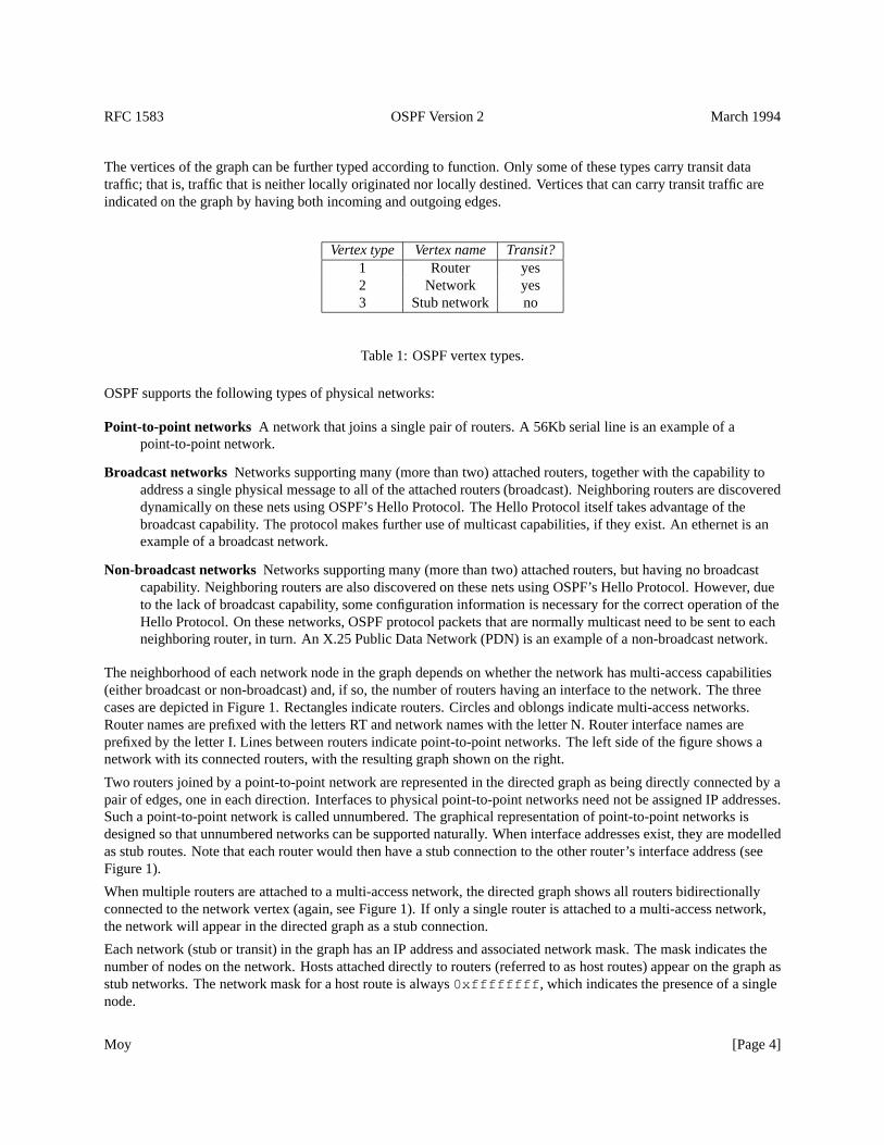
The vertices of the graph can be further typed according to function. Only some of these types carry transit datatraffic; that is, traffic that is neither locally originated nor locally destined. Vertices that can carry transit traffic areindicated on the graph by having both incoming and outgoing edges.
Vertex type Vertex name Transit?1 Router yes2 Network yes3 Stub network no
Table 1: OSPF vertex types.
OSPF supports the following types of physical networks:
Point-to-point networks A network that joins a single pair of routers. A 56Kb serial line is an example of apoint-to-point network.
Broadcast networks Networks supporting many (more than two) attached routers, together with the capability toaddress a single physical message to all of the attached routers (broadcast). Neighboring routers are discovereddynamically on these nets using OSPF’s Hello Protocol. The Hello Protocol itself takes advantage of thebroadcast capability. The protocol makes further use of multicast capabilities, if they exist. An ethernet is anexample of a broadcast network.
Non-broadcast networks Networks supporting many (more than two) attached routers, but having no broadcastcapability. Neighboring routers are also discovered on these nets using OSPF’s Hello Protocol. However, dueto the lack of broadcast capability, some configuration information is necessary for the correct operation of theHello Protocol. On these networks, OSPF protocol packets that are normally multicast need to be sent to eachneighboring router, in turn. An X.25 Public Data Network (PDN) is an example of a non-broadcast network.
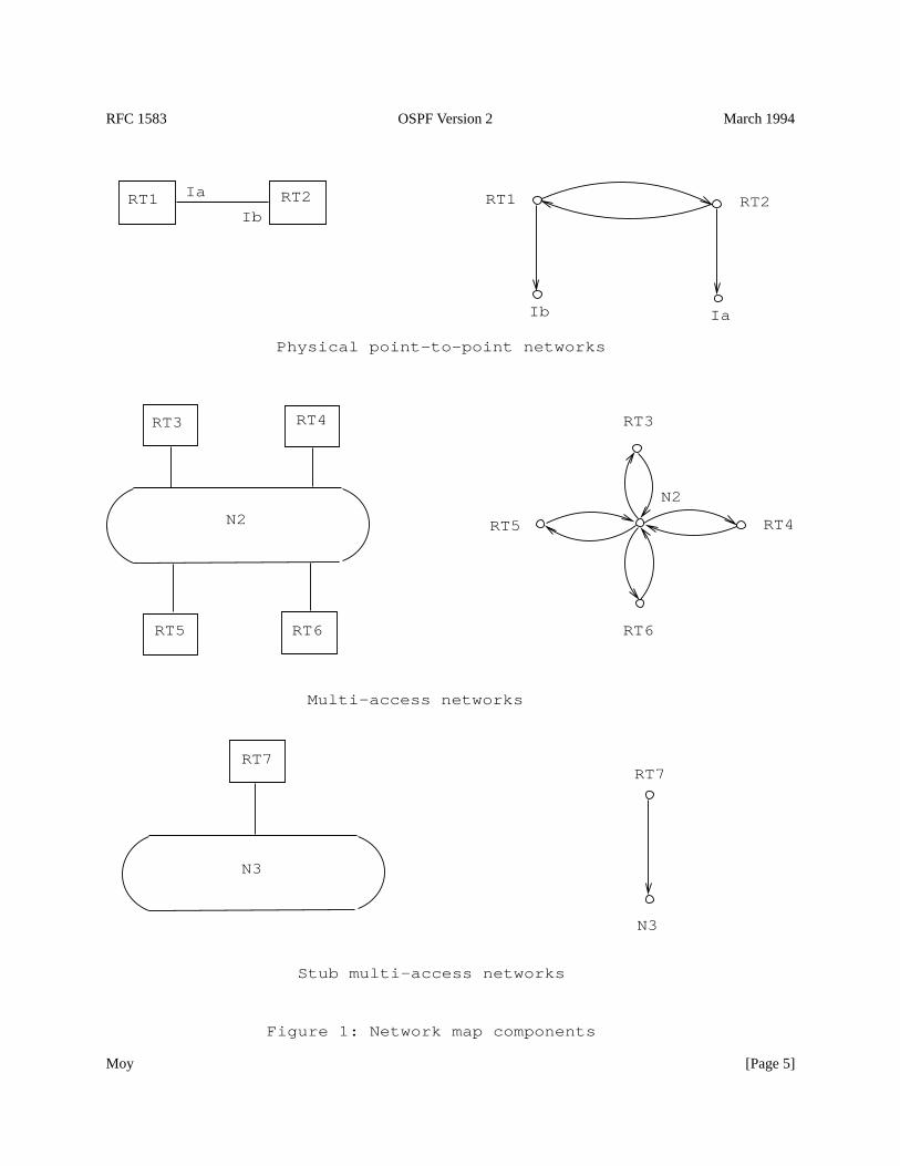
The neighborhood of each network node in the graph depends on whether the network has multi-access capabilities(either broadcast or non-broadcast) and, if so, the number of routers having an interface to the network. The threecases are depicted in Figure 1. Rectangles indicate routers. Circles and oblongs indicate multi-access networks.Router names are prefixed with the letters RT and network names with the letter N. Router interface names areprefixed by the letter I. Lines between routers indicate point-to-point networks. The left side of the figure shows anetwork with its connected routers, with the resulting graph shown on the right.
Two routers joined by a point-to-point network are represented in the directed graph as being directly connected by apair of edges, one in each direction. Interfaces to physical point-to-point networks need not be assigned IP addresses.Such a point-to-point network is called unnumbered. The graphical representation of point-to-point networks isdesigned so that unnumbered networks can be supported naturally. When interface addresses exist, they are modelledas stub routes. Note that each router would then have a stub connection to the other router’s interface address (seeFigure 1).
When multiple routers are attached to a multi-access network, the directed graph shows all routers bidirectionallyconnected to the network vertex (again, see Figure 1). If only a single router is attached to a multi-access network,the network will appear in the directed graph as a stub connection.
Each network (stub or transit) in the graph has an IP address and associated network mask. The mask indicates thenumber of nodes on the network. Hosts attached directly to routers (referred to as host routes) appear on the graph asstub networks. The network mask for a host route is always0xffffffff , which indicates the presence of a singlenode.
Moy [Page 4]
RFC 1583 OSPF Version 2 March 1994
Ib Ia
Ib
Ia
N2
RT2RT1RT2RT1
N2 RT5
RT6
RT4
RT3RT3
RT6RT5
RT4
RT7
N3
RT7
N3
Physical point-to-point networks
Multi-access networks
Stub multi-access networks
Figure 1: Network map components
Moy [Page 5]
RFC 1583 OSPF Version 2 March 1994
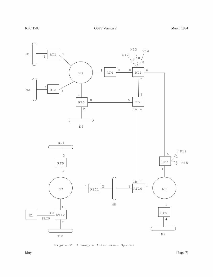
Figure 2 shows a sample map of an Autonomous System. The rectangle labelled H1 indicates a host, which has aSLIP connection to Router RT12. Router RT12 is therefore advertising a host route. Lines between routers indicatephysical point-to-point networks. The only point-to-point network that has been assigned interface addresses is theone joining Routers RT6 and RT10. Routers RT5 and RT7 have EGP connections to other Autonomous Systems. Aset of EGP-learned routes have been displayed for both of these routers.
A cost is associated with the output side of each router interface. This cost is configurable by the systemadministrator. The lower the cost, the more likely the interface is to be used to forward data traffic. Costs are alsoassociated with the externally derived routing data (e.g., the EGP-learned routes).
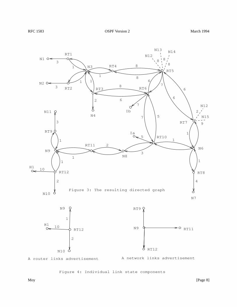
The directed graph resulting from the map in Figure 2 is depicted in Figure 3. Arcs are labelled with the cost of thecorresponding router output interface. Arcs having no labelled cost have a cost of 0. Note that arcs leading fromnetworks to routers always have cost 0; they are significant nonetheless. Note also that the externally derived routingdata appears on the graph as stubs.
The topological database (or what has been referred to above as the directed graph) is pieced together from link stateadvertisements generated by the routers. The neighborhood of each transit vertex is represented in a single, separatelink state advertisement. Figure 4 shows graphically the link state representation of the two kinds of transit vertices:routers and multi-access networks. Router RT12 has an interface to two broadcast networks and a SLIP line to a host.Network N6 is a broadcast network with three attached routers. The cost of all links from Network N6 to its attachedrouters is 0. Note that the link state advertisement for Network N6 is actually generated by one of the attachedrouters: the router that has been elected Designated Router for the network.
2.1 The shortest-path tree
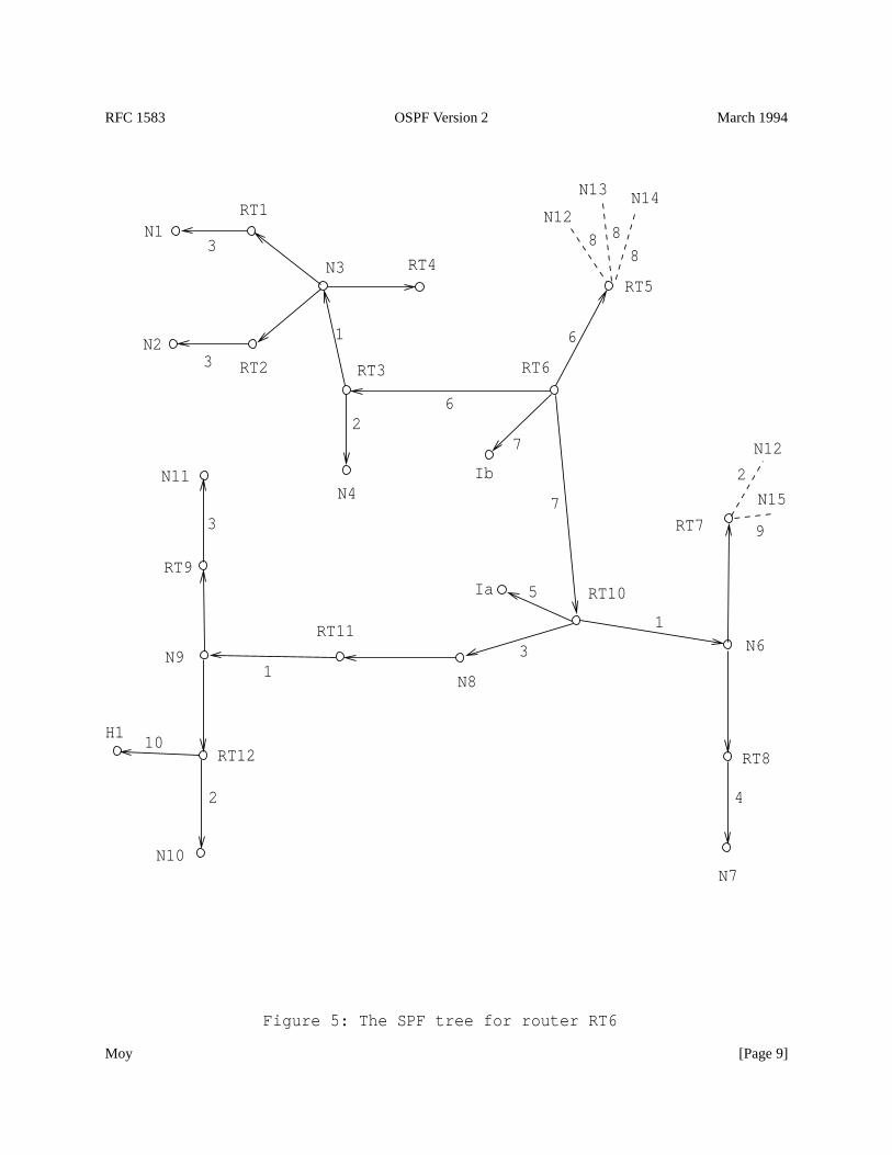
When no OSPF areas are configured, each router in the Autonomous System has an identical topological database,leading to an identical graphical representation. A router generates its routing table from this graph by calculating atree of shortest paths with the router itself as root. Obviously, the shortest-path tree depends on the router doing thecalculation. The shortest-path tree for Router RT6 in our example is depicted in Figure 5.
The tree gives the entire route to any destination network or host. However, only the next hop to the destination isused in the forwarding process. Note also that the best route to any router has also been calculated. For theprocessing of external data, we note the next hop and distance to any router advertising external routes. The resultingrouting table for Router RT6 is pictured in Table 2. Note that there is a separate route for each end of a numberedserial line (in this case, the serial line between Routers RT6 and RT10).
Routes to networks belonging to other AS’es (such as N12) appear as dashed lines on the shortest path tree in Figure5. Use of this externally derived routing information is considered in the next section.
2.2 Use of external routing information
After the tree is created the external routing information is examined. This external routing information mayoriginate from another routing protocol such as EGP, or be statically configured (static routes). Default routes canalso be included as part of the Autonomous System’s external routing information.
External routing information is flooded unaltered throughout the AS. In our example, all the routers in theAutonomous System know that Router RT7 has two external routes, with metrics 2 and 9.
OSPF supports two types of external metrics. Type 1 external metrics are equivalent to the link state metric. Type 2external metrics are greater than the cost of any path internal to the AS. Use of Type 2 external metrics assumes thatrouting between AS’es is the major cost of routing a packet, and eliminates the need for conversion of external coststo internal link state metrics.
Moy [Page 6]
RFC 1583 OSPF Version 2 March 1994
Ib
Ia
Figure 2: A sample Autonomous System
N1
N2
RT1
RT2
N3
RT3
N4
RT4 RT5
RT6
RT7
N6
RT8
RT10
N8
RT11N9
N11
RT9
RT12H1
N10
SLIP
N12
N13 N14
N12
N15
N7
31
11
1
3
1
1
1
1
1
1
5
32
3
2
10
4
6
68 8
6
7
7
68
2
8 88
2
9
Moy [Page 7]
RFC 1583 OSPF Version 2 March 1994
Ia
Ib
5
7
Figure 4: Individual link state components
Figure 3: The resulting directed graph
N15
N12
A network links advertisementA router links advertisement
RT11
N1
N2
RT1
RT2
N3
RT3
N4
RT4RT5
RT6
RT7
N6
RT8
RT10
N8
RT11
N11
N7
31
1 1
1
3
1
1
1
5
3
2
3
4
6
6
8
86
7
7
6
8
2
2
9
888
N14N13
N12
1
RT9
N9
RT12
11
10
2
N10
H1
H1
N10
2
10
1
RT12
N9
N9
RT9
RT12
Moy [Page 8]
RFC 1583 OSPF Version 2 March 1994
Ia
Ib
Figure 5: The SPF tree for router RT6
H1
N10
2
10RT12
N9
RT9
N12
N13 N14
8 88
9
2
2
7
6
4
3
3
1
3
1
3
N7
N11
RT11
N8
RT10
RT8
N6
RT7
RT6
RT5RT4
N4
RT3
N3
RT2
RT1
N2
N1
N12
N15
7
5
6
1
Moy [Page 9]
RFC 1583 OSPF Version 2 March 1994
Destination Next Hop DistanceN1 RT3 10N2 RT3 10N3 RT3 7N4 RT3 8Ib * 7Ia RT10 12N6 RT10 8N7 RT10 12N8 RT10 10N9 RT10 11N10 RT10 13N11 RT10 14H1 RT10 21
RT5 RT5 6RT7 RT10 8
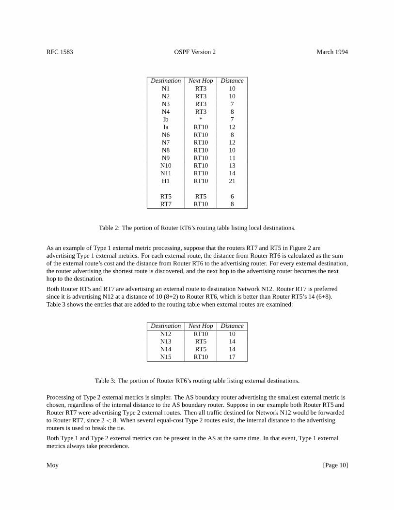
Table 2: The portion of Router RT6’s routing table listing local destinations.
As an example of Type 1 external metric processing, suppose that the routers RT7 and RT5 in Figure 2 areadvertising Type 1 external metrics. For each external route, the distance from Router RT6 is calculated as the sumof the external route’s cost and the distance from Router RT6 to the advertising router. For every external destination,the router advertising the shortest route is discovered, and the next hop to the advertising router becomes the nexthop to the destination.
Both Router RT5 and RT7 are advertising an external route to destination Network N12. Router RT7 is preferredsince it is advertising N12 at a distance of 10 (8+2) to Router RT6, which is better than Router RT5’s 14 (6+8).Table 3 shows the entries that are added to the routing table when external routes are examined:
Destination Next Hop DistanceN12 RT10 10N13 RT5 14N14 RT5 14N15 RT10 17
Table 3: The portion of Router RT6’s routing table listing external destinations.
Processing of Type 2 external metrics is simpler. The AS boundary router advertising the smallest external metric ischosen, regardless of the internal distance to the AS boundary router. Suppose in our example both Router RT5 andRouter RT7 were advertising Type 2 external routes. Then all traffic destined for Network N12 would be forwardedto Router RT7, since 2< 8. When several equal-cost Type 2 routes exist, the internal distance to the advertisingrouters is used to break the tie.
Both Type 1 and Type 2 external metrics can be present in the AS at the same time. In that event, Type 1 externalmetrics always take precedence.
Moy [Page 10]
RFC 1583 OSPF Version 2 March 1994
This section has assumed that packets destined for external destinations are always routed through the advertising ASboundary router. This is not always desirable. For example, suppose in Figure 2 there is an additional router attachedto Network N6, called Router RTX. Suppose further that RTX does not participate in OSPF routing, but doesexchange EGP information with the AS boundary router RT7. Then, Router RT7 would end up advertising OSPFexternal routes for all destinations that should be routed to RTX. An extra hop will sometimes be introduced ifpackets for these destinations need always be routed first to Router RT7 (the advertising router).
To deal with this situation, the OSPF protocol allows an AS boundary router to specify a “forwarding address” in itsexternal advertisements. In the above example, Router RT7 would specify RTX’s IP address as the “forwardingaddress” for all those destinations whose packets should be routed directly to RTX.
The “forwarding address” has one other application. It enables routers in the Autonomous System’s interior tofunction as “route servers”. For example, in Figure 2 the router RT6 could become a route server, gaining externalrouting information through a combination of static configuration and external routing protocols. RT6 would thenstart advertising itself as an AS boundary router, and would originate a collection of OSPF external advertisements.In each external advertisement, Router RT6 would specify the correct Autonomous System exit point to use for thedestination through appropriate setting of the advertisement’s “forwarding address” field.
2.3 Equal-cost multipath
The above discussion has been simplified by considering only a single route to any destination. In reality, if multipleequal-cost routes to a destination exist, they are all discovered and used. This requires no conceptual changes to thealgorithm, and its discussion is postponed until we consider the tree-building process in more detail.
With equal cost multipath, a router potentially has several available next hops towards any given destination.
2.4 TOS-based routing
OSPF can calculate a separate set of routes for each IP Type of Service. This means that, for any destination, therecan potentially be multiple routing table entries, one for each IP TOS. The IP TOS values are represented in OSPFexactly as they appear in the IP packet header.
Up to this point, all examples shown have assumed that routes do not vary on TOS. In order to differentiate routesbased on TOS, separate interface costs can be configured for each TOS. For example, in Figure 2 there could bemultiple costs (one for each TOS) listed for each interface. A cost for TOS 0 must always be specified.
When interface costs vary based on TOS, a separate shortest path tree is calculated for each TOS (see Section 2.1). Inaddition, external costs can vary based on TOS. For example, in Figure 2 Router RT7 could advertise a separate type1 external metric for each TOS. Then, when calculating the TOS X distance to Network N15 the cost of the shortestTOS X path to RT7 would be added to the TOS X cost advertised by RT7 for Network N15 (see Section 2.2).
All OSPF implementations must be capable of calculating routes based on TOS. However, OSPF routers can beconfigured to route all packets on the TOS 0 path (see Appendix C), eliminating the need to calculate non-zero TOSpaths. This can be used to conserve routing table space and processing resources in the router. These TOS-0-onlyrouters can be mixed with routers that do route based on TOS. TOS-0-only routers will be avoided as much aspossible when forwarding traffic requesting a non-zero TOS.
It may be the case that no path exists for some non-zero TOS, even if the router is calculating non-zero TOS paths. Inthat case, packets requesting that non-zero TOS are routed along the TOS 0 path (see Section 11.1).
Moy [Page 11]
RFC 1583 OSPF Version 2 March 1994
3 Splitting the AS into Areas
OSPF allows collections of contiguous networks and hosts to be grouped together. Such a group, together with therouters having interfaces to any one of the included networks, is called an area. Each area runs a separate copy of thebasic link-state routing algorithm. This means that each area has its own topological database and correspondinggraph, as explained in the previous section.
The topology of an area is invisible from the outside of the area. Conversely, routers internal to a given area knownothing of the detailed topology external to the area. This isolation of knowledge enables the protocol to effect amarked reduction in routing traffic as compared to treating the entire Autonomous System as a single link-statedomain.
With the introduction of areas, it is no longer true that all routers in the AS have an identical topological database. Arouter actually has a separate topological database for each area it is connected to. (Routers connected to multipleareas are called area border routers). Two routers belonging to the same area have, for that area, identical areatopological databases.
Routing in the Autonomous System takes place on two levels, depending on whether the source and destination of apacket reside in the same area (intra-area routing is used) or different areas (inter-area routing is used). In intra-arearouting, the packet is routed solely on information obtained within the area; no routing information obtained fromoutside the area can be used. This protects intra-area routing from the injection of bad routing information. Wediscuss inter-area routing in Section 3.2.
3.1 The backbone of the Autonomous System
The backbone consists of those networks not contained in any area, their attached routers, and those routers thatbelong to multiple areas. The backbone must be contiguous.
It is possible to define areas in such a way that the backbone is no longer contiguous. In this case the systemadministrator must restore backbone connectivity by configuring virtual links.
Virtual links can be configured between any two backbone routers that have an interface to a common non-backbonearea. Virtual links belong to the backbone. The protocol treats two routers joined by a virtual link as if they wereconnected by an unnumbered point-to-point network. On the graph of the backbone, two such routers are joined byarcs whose costs are the intra-area distances between the two routers. The routing protocol traffic that flows along thevirtual link uses intra-area routing only.
The backbone is responsible for distributing routing information between areas. The backbone itself has all of theproperties of an area. The topology of the backbone is invisible to each of the areas, while the backbone itself knowsnothing of the topology of the areas.
3.2 Inter-area routing
When routing a packet between two areas the backbone is used. The path that the packet will travel can be broken upinto three contiguous pieces: an intra-area path from the source to an area border router, a backbone path between thesource and destination areas, and then another intra-area path to the destination. The algorithm finds the set of suchpaths that have the smallest cost.
Looking at this another way, inter-area routing can be pictured as forcing a star configuration on the AutonomousSystem, with the backbone as hub and each of the areas as spokes.
The topology of the backbone dictates the backbone paths used between areas. The topology of the backbone can beenhanced by adding virtual links. This gives the system administrator some control over the routes taken byinter-area traffic.
Moy [Page 12]
RFC 1583 OSPF Version 2 March 1994
The correct area border router to use as the packet exits the source area is chosen in exactly the same way routersadvertising external routes are chosen. Each area border router in an area summarizes for the area its cost to allnetworks external to the area. After the SPF tree is calculated for the area, routes to all other networks are calculatedby examining the summaries of the area border routers.
3.3 Classification of routers
Before the introduction of areas, the only OSPF routers having a specialized function were those advertising externalrouting information, such as Router RT5 in Figure 2. When the AS is split into OSPF areas, the routers are furtherdivided according to function into the following four overlapping categories:
Internal routers A router with all directly connected networks belonging to the same area. Routers with onlybackbone interfaces also belong to this category. These routers run a single copy of the basic routing algorithm.
Area border routers A router that attaches to multiple areas. Area border routers run multiple copies of the basicalgorithm, one copy for each attached area and an additional copy for the backbone. Area border routerscondense the topological information of their attached areas for distribution to the backbone. The backbone inturn distributes the information to the other areas.
Backbone routers A router that has an interface to the backbone. This includes all routers that interface to morethan one area (i.e., area border routers). However, backbone routers do not have to be area border routers.Routers with all interfaces connected to the backbone are considered to be internal routers.
AS boundary routers A router that exchanges routing information with routers belonging to other AutonomousSystems. Such a router has AS external routes that are advertised throughout the Autonomous System. Thepath to each AS boundary router is known by every router in the AS. This classification is completelyindependent of the previous classifications: AS boundary routers may be internal or area border routers, andmay or may not participate in the backbone.
3.4 A sample area configuration
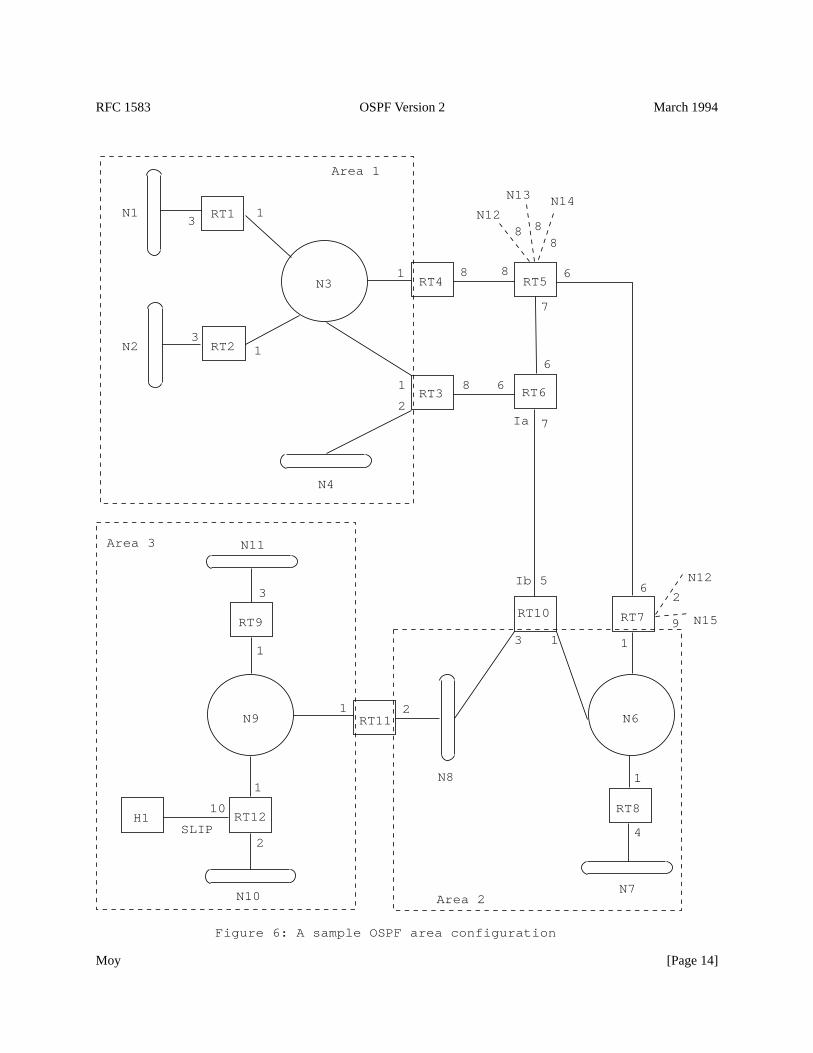
Figure 6 shows a sample area configuration. The first area consists of networks N1-N4, along with their attachedrouters RT1-RT4. The second area consists of networks N6-N8, along with their attached routers RT7, RT8, RT10and RT11. The third area consists of networks N9-N11 and Host H1, along with their attached routers RT9, RT11and RT12. The third area has been configured so that networks N9-N11 and Host H1 will all be grouped into a singleroute, when advertised external to the area (see Section 3.5 for more details).
In Figure 6, Routers RT1, RT2, RT5, RT6, RT8, RT9 and RT12 are internal routers. Routers RT3, RT4, RT7, RT10and RT11 are area border routers. Finally, as before, Routers RT5 and RT7 are AS boundary routers.
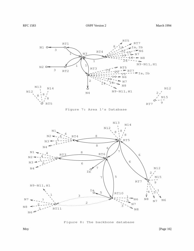
Figure 7 shows the resulting topological database for the Area 1. The figure completely describes that area’sintra-area routing. It also shows the complete view of the internet for the two internal routers RT1 and RT2. It is thejob of the area border routers, RT3 and RT4, to advertise into Area 1 the distances to all destinations external to thearea. These are indicated in Figure 7 by the dashed stub routes. Also, RT3 and RT4 must advertise into Area 1 thelocation of the AS boundary routers RT5 and RT7. Finally, external advertisements from RT5 and RT7 are floodedthroughout the entire AS, and in particular throughout Area 1. These advertisements are included in Area 1’sdatabase, and yield routes to networks N12-N15.
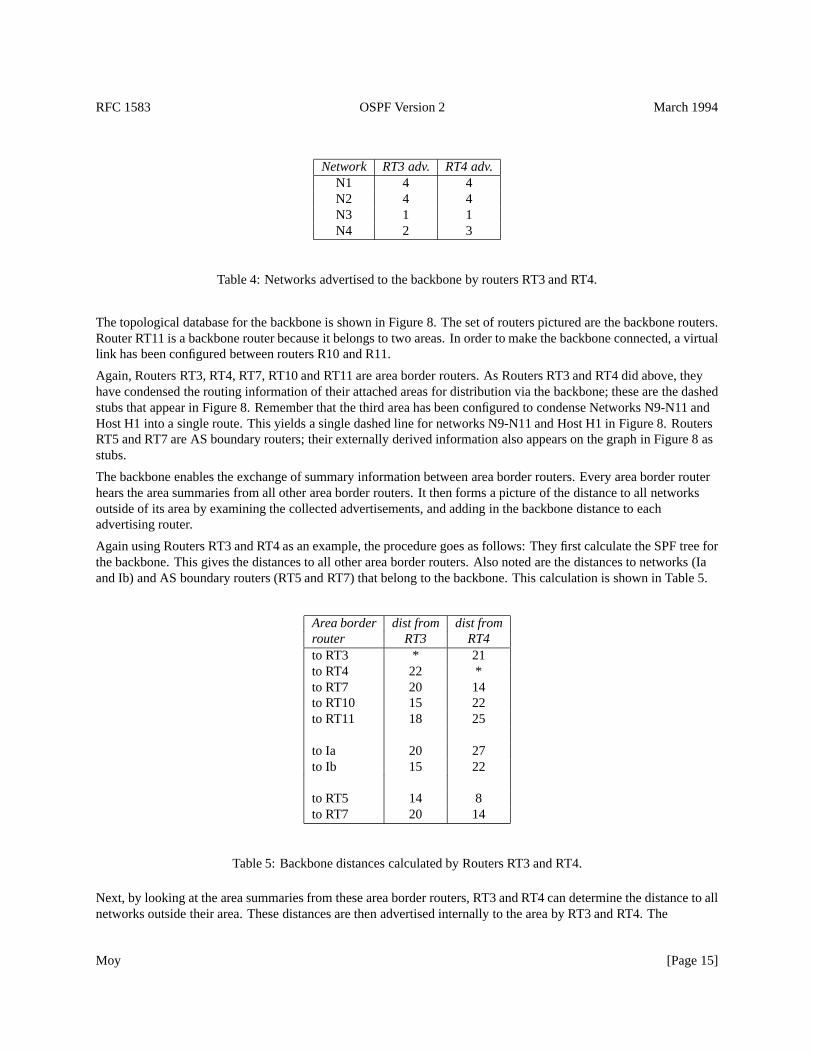
Routers RT3 and RT4 must also summarize Area 1’s topology for distribution to the backbone. Their backboneadvertisements are shown in Table 4. These summaries show which networks are contained in Area 1 (i.e., NetworksN1-N4), and the distance to these networks from the routers RT3 and RT4 respectively.
Moy [Page 13]
RFC 1583 OSPF Version 2 March 1994
Ib
Ia
Figure 6: A sample OSPF area configuration
Area 3
Area 2
Area 1
N1
N2
RT1
RT2
N3
RT3
N4
RT4 RT5
RT6
RT7
N6
RT8
RT10
N8
RT11N9
N11
RT9
RT12H1
N10
SLIP
N12
N13 N14
N12
N15
N7
31
1
1
1
3
11
1
1
1
1
5
3
2
3
2
10
4
6
68 8
6
7
7
68
2
8 88
2
9
Moy [Page 14]
RFC 1583 OSPF Version 2 March 1994
Network RT3 adv. RT4 adv.N1 4 4N2 4 4N3 1 1N4 2 3
Table 4: Networks advertised to the backbone by routers RT3 and RT4.
The topological database for the backbone is shown in Figure 8. The set of routers pictured are the backbone routers.Router RT11 is a backbone router because it belongs to two areas. In order to make the backbone connected, a virtuallink has been configured between routers R10 and R11.
Again, Routers RT3, RT4, RT7, RT10 and RT11 are area border routers. As Routers RT3 and RT4 did above, theyhave condensed the routing information of their attached areas for distribution via the backbone; these are the dashedstubs that appear in Figure 8. Remember that the third area has been configured to condense Networks N9-N11 andHost H1 into a single route. This yields a single dashed line for networks N9-N11 and Host H1 in Figure 8. RoutersRT5 and RT7 are AS boundary routers; their externally derived information also appears on the graph in Figure 8 asstubs.
The backbone enables the exchange of summary information between area border routers. Every area border routerhears the area summaries from all other area border routers. It then forms a picture of the distance to all networksoutside of its area by examining the collected advertisements, and adding in the backbone distance to eachadvertising router.
Again using Routers RT3 and RT4 as an example, the procedure goes as follows: They first calculate the SPF tree forthe backbone. This gives the distances to all other area border routers. Also noted are the distances to networks (Iaand Ib) and AS boundary routers (RT5 and RT7) that belong to the backbone. This calculation is shown in Table 5.
Area border dist from dist fromrouter RT3 RT4to RT3 * 21to RT4 22 *to RT7 20 14to RT10 15 22to RT11 18 25
to Ia 20 27to Ib 15 22
to RT5 14 8to RT7 20 14
Table 5: Backbone distances calculated by Routers RT3 and RT4.
Next, by looking at the area summaries from these area border routers, RT3 and RT4 can determine the distance to allnetworks outside their area. These distances are then advertised internally to the area by RT3 and RT4. The
Moy [Page 15]
RFC 1583 OSPF Version 2 March 1994
7
3
N7
N6
15
1819
1522Ia,Ib
Ia
Ib
Ia,Ib
5
7
Figure 8: The backbone database
Figure 7: Area 1’s Database
19 1820
16
2014
26
148
RT7
2
3
1
11
13
RT4
N4
RT3
N3
RT2
RT1
N2
N1
N9-N11,H1
N8N7
N6
RT7RT5
N9-N11,H1
N8N7N6
RT7RT5
N12
N13 N14
8 88
RT5
N15
2
9
N12
N15
N12
RT3
RT4RT5
RT6
RT7
RT10
RT11
5
6
6
8
86
7
7
6
8
2
9
888
N14N12
N13
N1
N2
N3
N4
N1
N2
N3
N4
N9-N11,H1
N8N8
N8N6
N7N6N7
3
2
44
13
4412
1
2 3
15
154
Moy [Page 16]
RFC 1583 OSPF Version 2 March 1994
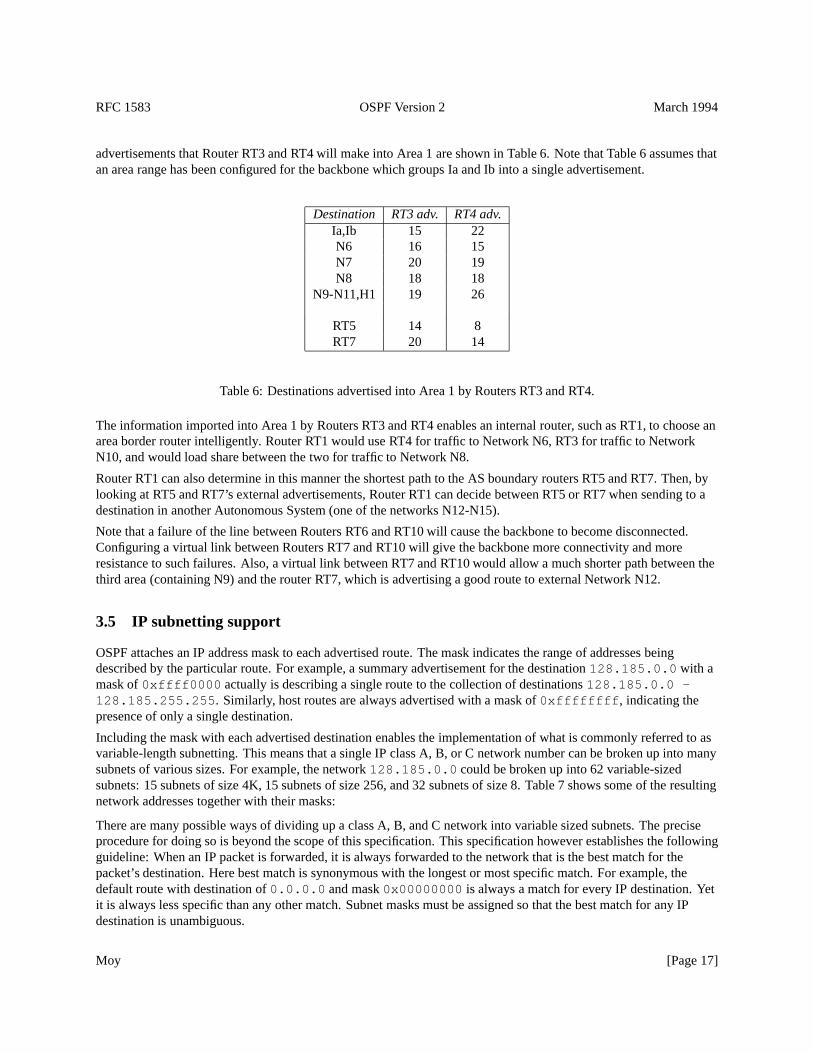
advertisements that Router RT3 and RT4 will make into Area 1 are shown in Table 6. Note that Table 6 assumes thatan area range has been configured for the backbone which groups Ia and Ib into a single advertisement.
Destination RT3 adv. RT4 adv.Ia,Ib 15 22N6 16 15N7 20 19N8 18 18
N9-N11,H1 19 26
RT5 14 8RT7 20 14
Table 6: Destinations advertised into Area 1 by Routers RT3 and RT4.
The information imported into Area 1 by Routers RT3 and RT4 enables an internal router, such as RT1, to choose anarea border router intelligently. Router RT1 would use RT4 for traffic to Network N6, RT3 for traffic to NetworkN10, and would load share between the two for traffic to Network N8.
Router RT1 can also determine in this manner the shortest path to the AS boundary routers RT5 and RT7. Then, bylooking at RT5 and RT7’s external advertisements, Router RT1 can decide between RT5 or RT7 when sending to adestination in another Autonomous System (one of the networks N12-N15).
Note that a failure of the line between Routers RT6 and RT10 will cause the backbone to become disconnected.Configuring a virtual link between Routers RT7 and RT10 will give the backbone more connectivity and moreresistance to such failures. Also, a virtual link between RT7 and RT10 would allow a much shorter path between thethird area (containing N9) and the router RT7, which is advertising a good route to external Network N12.
3.5 IP subnetting support
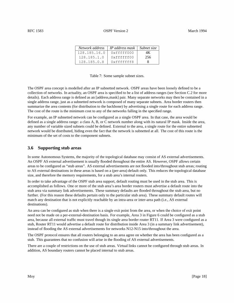
OSPF attaches an IP address mask to each advertised route. The mask indicates the range of addresses beingdescribed by the particular route. For example, a summary advertisement for the destination128.185.0.0 with amask of0xffff0000 actually is describing a single route to the collection of destinations128.185.0.0 -128.185.255.255 . Similarly, host routes are always advertised with a mask of0xffffffff , indicating thepresence of only a single destination.
Including the mask with each advertised destination enables the implementation of what is commonly referred to asvariable-length subnetting. This means that a single IP class A, B, or C network number can be broken up into manysubnets of various sizes. For example, the network128.185.0.0 could be broken up into 62 variable-sizedsubnets: 15 subnets of size 4K, 15 subnets of size 256, and 32 subnets of size 8. Table 7 shows some of the resultingnetwork addresses together with their masks:
There are many possible ways of dividing up a class A, B, and C network into variable sized subnets. The preciseprocedure for doing so is beyond the scope of this specification. This specification however establishes the followingguideline: When an IP packet is forwarded, it is always forwarded to the network that is the best match for thepacket’s destination. Here best match is synonymous with the longest or most specific match. For example, thedefault route with destination of0.0.0.0 and mask0x00000000 is always a match for every IP destination. Yetit is always less specific than any other match. Subnet masks must be assigned so that the best match for any IPdestination is unambiguous.
Moy [Page 17]
RFC 1583 OSPF Version 2 March 1994
Network address IP address mask Subnet size128.185.16.0 0xfffff000 4K128.185.1.0 0xffffff00 256128.185.0.8 0xfffffff8 8
Table 7: Some sample subnet sizes.
The OSPF area concept is modelled after an IP subnetted network. OSPF areas have been loosely defined to be acollection of networks. In actuality, an OSPF area is specified to be a list of address ranges (see Section C.2 for moredetails). Each address range is defined as an [address,mask] pair. Many separate networks may then be contained in asingle address range, just as a subnetted network is composed of many separate subnets. Area border routers thensummarize the area contents (for distribution to the backbone) by advertising a single route for each address range.The cost of the route is the minimum cost to any of the networks falling in the specified range.
For example, an IP subnetted network can be configured as a single OSPF area. In that case, the area would bedefined as a single address range: a class A, B, or C network number along with its natural IP mask. Inside the area,any number of variable sized subnets could be defined. External to the area, a single route for the entire subnettednetwork would be distributed, hiding even the fact that the network is subnetted at all. The cost of this route is theminimum of the set of costs to the component subnets.
3.6 Supporting stub areas
In some Autonomous Systems, the majority of the topological database may consist of AS external advertisements.An OSPF AS external advertisement is usually flooded throughout the entire AS. However, OSPF allows certainareas to be configured as “stub areas”. AS external advertisements are not flooded into/throughout stub areas; routingto AS external destinations in these areas is based on a (per-area) default only. This reduces the topological databasesize, and therefore the memory requirements, for a stub area’s internal routers.
In order to take advantage of the OSPF stub area support, default routing must be used in the stub area. This isaccomplished as follows. One or more of the stub area’s area border routers must advertise a default route into thestub area via summary link advertisements. These summary defaults are flooded throughout the stub area, but nofurther. (For this reason these defaults pertain only to the particular stub area). These summary default routes willmatch any destination that is not explicitly reachable by an intra-area or inter-area path (i.e., AS externaldestinations).
An area can be configured as stub when there is a single exit point from the area, or when the choice of exit pointneed not be made on a per-external-destination basis. For example, Area 3 in Figure 6 could be configured as a stubarea, because all external traffic must travel though its single area border router RT11. If Area 3 were configured as astub, Router RT11 would advertise a default route for distribution inside Area 3 (in a summary link advertisement),instead of flooding the AS external advertisements for networks N12-N15 into/throughout the area.
The OSPF protocol ensures that all routers belonging to an area agree on whether the area has been configured as astub. This guarantees that no confusion will arise in the flooding of AS external advertisements.
There are a couple of restrictions on the use of stub areas. Virtual links cannot be configured through stub areas. Inaddition, AS boundary routers cannot be placed internal to stub areas.
Moy [Page 18]
RFC 1583 OSPF Version 2 March 1994
3.7 Partitions of areas
OSPF does not actively attempt to repair area partitions. When an area becomes partitioned, each component simplybecomes a separate area. The backbone then performs routing between the new areas. Some destinations reachablevia intra-area routing before the partition will now require inter-area routing.
In the previous section, an area was described as a list of address ranges. Any particular address range must still becompletely contained in a single component of the area partition. This has to do with the way the area contents aresummarized to the backbone. Also, the backbone itself must not partition. If it does, parts of the AutonomousSystem will become unreachable. Backbone partitions can be repaired by configuring virtual links (see Section 15).
Another way to think about area partitions is to look at the Autonomous System graph that was introduced inSection 2. Area IDs can be viewed as colors for the graph’s edges.1 Each edge of the graph connects to a network, oris itself a point-to-point network. In either case, the edge is colored with the network’s Area ID.
A group of edges, all having the same color, and interconnected by vertices, represents an area. If the topology of theAutonomous System is intact, the graph will have several regions of color, each color being a distinct Area ID.
When the AS topology changes, one of the areas may become partitioned. The graph of the AS will then havemultiple regions of the same color (Area ID). The routing in the Autonomous System will continue to function aslong as these regions of same color are connected by the single backbone region.
1The graph’s vertices represent either routers, transit networks, or stub networks. Since routers may belong to multiple areas, it is not possibleto color the graph’s vertices.
Moy [Page 19]
RFC 1583 OSPF Version 2 March 1994
4 Functional Summary
A separate copy of OSPF’s basic routing algorithm runs in each area. Routers having interfaces to multiple areas runmultiple copies of the algorithm. A brief summary of the routing algorithm follows.
When a router starts, it first initializes the routing protocol data structures. The router then waits for indications fromthe lower-level protocols that its interfaces are functional.
A router then uses the OSPF’s Hello Protocol to acquire neighbors. The router sends Hello packets to its neighbors,and in turn receives their Hello packets. On broadcast and point-to-point networks, the router dynamically detects itsneighboring routers by sending its Hello packets to the multicast address AllSPFRouters. On non-broadcastnetworks, some configuration information is necessary in order to discover neighbors. On all multi-access networks(broadcast or non-broadcast), the Hello Protocol also elects a Designated router for the network.
The router will attempt to form adjacencies with some of its newly acquired neighbors. Topological databases aresynchronized between pairs of adjacent routers. On multi-access networks, the Designated Router determines whichrouters should become adjacent.
Adjacencies control the distribution of routing protocol packets. Routing protocol packets are sent and received onlyon adjacencies. In particular, distribution of topological database updates proceeds along adjacencies.
A router periodically advertises its state, which is also called link state. Link state is also advertised when a router’sstate changes. A router’s adjacencies are reflected in the contents of its link state advertisements. This relationshipbetween adjacencies and link state allows the protocol to detect dead routers in a timely fashion.
Link state advertisements are flooded throughout the area. The flooding algorithm is reliable, ensuring that all routersin an area have exactly the same topological database. This database consists of the collection of link stateadvertisements received from each router belonging to the area. From this database each router calculates ashortest-path tree, with itself as root. This shortest-path tree in turn yields a routing table for the protocol.
4.1 Inter-area routing
The previous section described the operation of the protocol within a single area. For intra-area routing, no otherrouting information is pertinent. In order to be able to route to destinations outside of the area, the area border routersinject additional routing information into the area. This additional information is a distillation of the rest of theAutonomous System’s topology.
This distillation is accomplished as follows: Each area border router is by definition connected to the backbone.Each area border router summarizes the topology of its attached areas for transmission on the backbone, and hence toall other area border routers. An area border router then has complete topological information concerning thebackbone, and the area summaries from each of the other area border routers. From this information, the routercalculates paths to all destinations not contained in its attached areas. The router then advertises these paths into itsattached areas. This enables the area’s internal routers to pick the best exit router when forwarding traffic todestinations in other areas.
4.2 AS external routes
Routers that have information regarding other Autonomous Systems can flood this information throughout the AS.This external routing information is distributed verbatim to every participating router. There is one exception:external routing information is not flooded into “stub” areas (see Section 3.6).
To utilize external routing information, the path to all routers advertising external information must be knownthroughout the AS (excepting the stub areas). For that reason, the locations of these AS boundary routers aresummarized by the (non-stub) area border routers.
Moy [Page 20]
RFC 1583 OSPF Version 2 March 1994
4.3 Routing protocol packets
The OSPF protocol runs directly over IP, using IP protocol 89. OSPF does not provide any explicitfragmentation/reassembly support. When fragmentation is necessary, IP fragmentation/reassembly is used. OSPFprotocol packets have been designed so that large protocol packets can generally be split into several smallerprotocol packets. This practice is recommended; IP fragmentation should be avoided whenever possible.
Routing protocol packets should always be sent with the IP TOS field set to 0. If at all possible, routing protocolpackets should be given preference over regular IP data traffic, both when being sent and received. As an aid toaccomplishing this, OSPF protocol packets should have their IP precedence field set to the value InternetworkControl (see [RFC 791]).
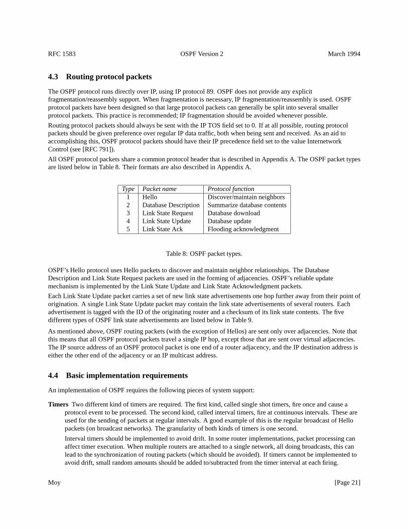
All OSPF protocol packets share a common protocol header that is described in Appendix A. The OSPF packet typesare listed below in Table 8. Their formats are also described in Appendix A.
Type Packet name Protocol function1 Hello Discover/maintain neighbors2 Database Description Summarize database contents3 Link State Request Database download4 Link State Update Database update5 Link State Ack Flooding acknowledgment
Table 8: OSPF packet types.
OSPF’s Hello protocol uses Hello packets to discover and maintain neighbor relationships. The DatabaseDescription and Link State Request packets are used in the forming of adjacencies. OSPF’s reliable updatemechanism is implemented by the Link State Update and Link State Acknowledgment packets.
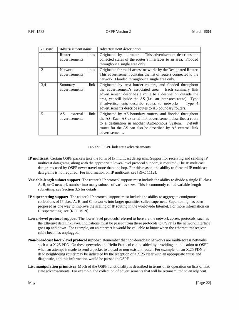
Each Link State Update packet carries a set of new link state advertisements one hop further away from their point oforigination. A single Link State Update packet may contain the link state advertisements of several routers. Eachadvertisement is tagged with the ID of the originating router and a checksum of its link state contents. The fivedifferent types of OSPF link state advertisements are listed below in Table 9.
As mentioned above, OSPF routing packets (with the exception of Hellos) are sent only over adjacencies. Note thatthis means that all OSPF protocol packets travel a single IP hop, except those that are sent over virtual adjacencies.The IP source address of an OSPF protocol packet is one end of a router adjacency, and the IP destination address iseither the other end of the adjacency or an IP multicast address.
4.4 Basic implementation requirements
An implementation of OSPF requires the following pieces of system support:
Timers Two different kind of timers are required. The first kind, called single shot timers, fire once and cause aprotocol event to be processed. The second kind, called interval timers, fire at continuous intervals. These areused for the sending of packets at regular intervals. A good example of this is the regular broadcast of Hellopackets (on broadcast networks). The granularity of both kinds of timers is one second.
Interval timers should be implemented to avoid drift. In some router implementations, packet processing canaffect timer execution. When multiple routers are attached to a single network, all doing broadcasts, this canlead to the synchronization of routing packets (which should be avoided). If timers cannot be implemented toavoid drift, small random amounts should be added to/subtracted from the timer interval at each firing.
Moy [Page 21]
RFC 1583 OSPF Version 2 March 1994
LS type Advertisement name Advertisement description
1 Router linksadvertisements
Originated by all routers. This advertisement describes thecollected states of the router’s interfaces to an area. Floodedthroughout a single area only.
2 Network linksadvertisements
Originated for multi-access networks by the Designated Router.This advertisement contains the list of routers connected to thenetwork. Flooded throughout a single area only.
3,4 Summary linkadvertisements
Originated by area border routers, and flooded throughoutthe advertisement’s associated area. Each summary linkadvertisement describes a route to a destination outside thearea, yet still inside the AS (i.e., an inter-area route). Type3 advertisements describe routes to networks. Type 4advertisements describe routes to AS boundary routers.
5 AS external linkadvertisements
Originated by AS boundary routers, and flooded throughoutthe AS. Each AS external link advertisement describes a routeto a destination in another Autonomous System. Defaultroutes for the AS can also be described by AS external linkadvertisements.
Table 9: OSPF link state advertisements.
IP multicast Certain OSPF packets take the form of IP multicast datagrams. Support for receiving and sending IPmulticast datagrams, along with the appropriate lower-level protocol support, is required. The IP multicastdatagrams used by OSPF never travel more than one hop. For this reason, the ability to forward IP multicastdatagrams is not required. For information on IP multicast, see [RFC 1112].
Variable-length subnet support The router’s IP protocol support must include the ability to divide a single IP classA, B, or C network number into many subnets of various sizes. This is commonly called variable-lengthsubnetting; see Section 3.5 for details.
IP supernetting support The router’s IP protocol support must include the ability to aggregate contiguouscollections of IP class A, B, and C networks into larger quantities called supernets. Supernetting has beenproposed as one way to improve the scaling of IP routing in the worldwide Internet. For more information onIP supernetting, see [RFC 1519].
Lower-level protocol support The lower level protocols referred to here are the network access protocols, such asthe Ethernet data link layer. Indications must be passed from these protocols to OSPF as the network interfacegoes up and down. For example, on an ethernet it would be valuable to know when the ethernet transceivercable becomes unplugged.
Non-broadcast lower-level protocol support Remember that non-broadcast networks are multi-access networkssuch as a X.25 PDN. On these networks, the Hello Protocol can be aided by providing an indication to OSPFwhen an attempt is made to send a packet to a dead or non-existent router. For example, on an X.25 PDN adead neighboring router may be indicated by the reception of a X.25 clear with an appropriate cause anddiagnostic, and this information would be passed to OSPF.
List manipulation primitives Much of the OSPF functionality is described in terms of its operation on lists of linkstate advertisements. For example, the collection of advertisements that will be retransmitted to an adjacent
Moy [Page 22]
RFC 1583 OSPF Version 2 March 1994
router until acknowledged are described as a list. Any particular advertisement may be on many such lists. AnOSPF implementation needs to be able to manipulate these lists, adding and deleting constituentadvertisements as necessary.
Tasking support Certain procedures described in this specification invoke other procedures. At times, these otherprocedures should be executed in-line, that is, before the current procedure is finished. This is indicated in thetext by instructions toexecutea procedure. At other times, the other procedures are to be executed only whenthe current procedure has finished. This is indicated by instructions toschedulea task.
4.5 Optional OSPF capabilities
The OSPF protocol defines several optional capabilities. A router indicates the optional capabilities that it supportsin its OSPF Hello packets, Database Description packets and in its link state advertisements. This enables routerssupporting a mix of optional capabilities to coexist in a single Autonomous System.
Some capabilities must be supported by all routers attached to a specific area. In this case, a router will not accept aneighbor’s Hello Packet unless there is a match in reported capabilities (i.e., a capability mismatch prevents aneighbor relationship from forming). An example of this is the ExternalRoutingCapability (see below).
Other capabilities can be negotiated during the Database Exchange process. This is accomplished by specifying theoptional capabilities in Database Description packets. A capability mismatch with a neighbor in this case will resultin only a subset of link state advertisements being exchanged between the two neighbors.
The routing table build process can also be affected by the presence/absence of optional capabilities. For example,since the optional capabilities are reported in link state advertisements, routers incapable of certain functions can beavoided when building the shortest path tree. An example of this is the TOS routing capability (see below).
The current OSPF optional capabilities are listed below. See Section A.2 for more information.
ExternalRoutingCapability Entire OSPF areas can be configured as “stubs” (see Section 3.6). AS externaladvertisements will not be flooded into stub areas. This capability is represented by theE-bit in the OSPFoptions field (see Section A.2). In order to ensure consistent configuration of stub areas, all routers interfacingto such an area must have theE-bit clear in their Hello packets (see Sections 9.5 and 10.5).
TOS capability All OSPF implementations must be able to calculate separate routes based on IP Type of Service.However, to save routing table space and processing resources, an OSPF router can be configured to ignoreTOS when forwarding packets. In this case, the router calculates routes for TOS 0 only. This capability isrepresented by theT-bit in the OSPF options field (see Section A.2). TOS-capable routers will attempt toavoid non-TOS-capable routers when calculating non-zero TOS paths.
5 Protocol Data Structures
The OSPF protocol is described in this specification in terms of its operation on various protocol data structures. Thefollowing list comprises the top-level OSPF data structures. Any initialization that needs to be done is noted. OSPFareas, interfaces and neighbors also have associated data structures that are described later in this specification.
Router ID A 32-bit number that uniquely identifies this router in the AS. One possible implementation strategywould be to use the smallest IP interface address belonging to the router. If a router’s OSPF Router ID ischanged, the router’s OSPF software should be restarted before the new Router ID takes effect. Beforerestarting in order to change its Router ID, the router should flush its self-originated link state advertisementsfrom the routing domain (see Section 14.1), or they will persist for up to MaxAge minutes.
Moy [Page 23]
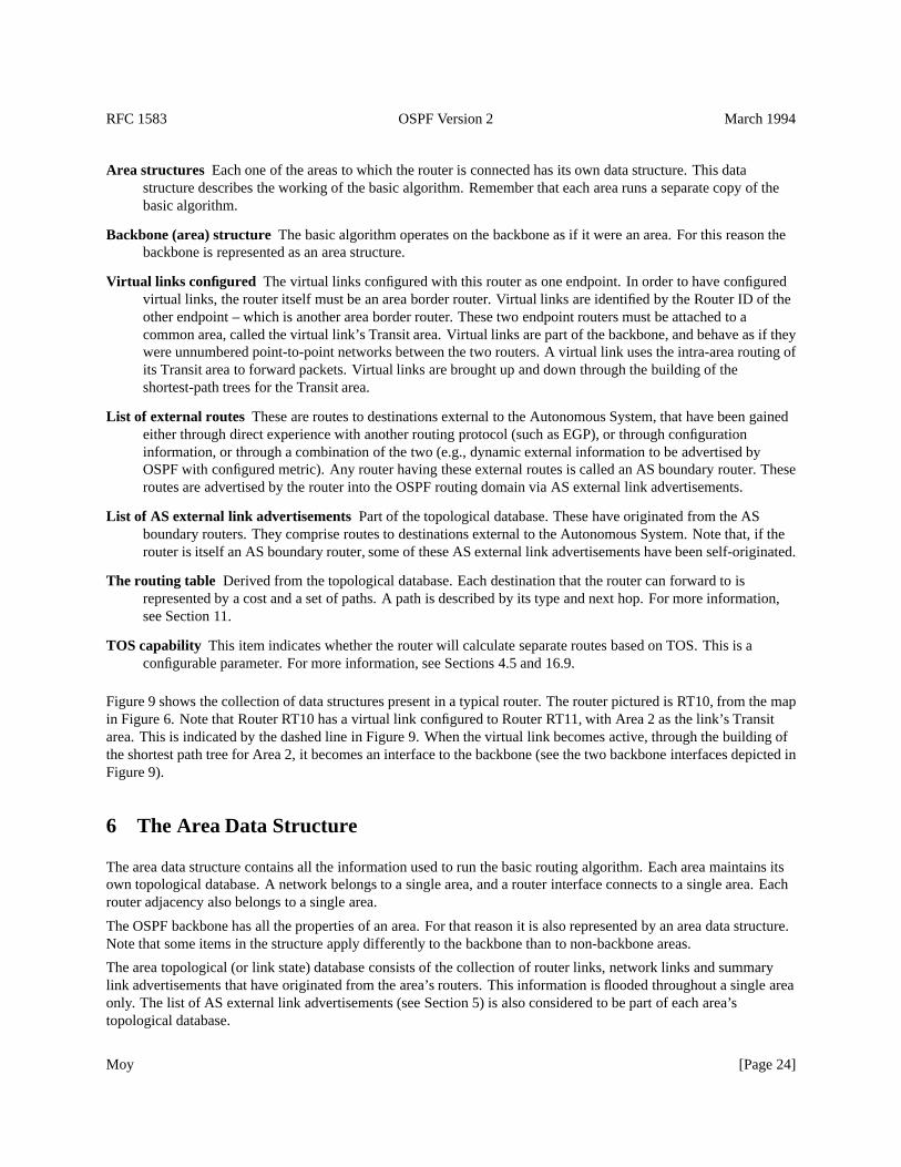
RFC 1583 OSPF Version 2 March 1994
Area structures Each one of the areas to which the router is connected has its own data structure. This datastructure describes the working of the basic algorithm. Remember that each area runs a separate copy of thebasic algorithm.
Backbone (area) structure The basic algorithm operates on the backbone as if it were an area. For this reason thebackbone is represented as an area structure.
Virtual links configured The virtual links configured with this router as one endpoint. In order to have configuredvirtual links, the router itself must be an area border router. Virtual links are identified by the Router ID of theother endpoint – which is another area border router. These two endpoint routers must be attached to acommon area, called the virtual link’s Transit area. Virtual links are part of the backbone, and behave as if theywere unnumbered point-to-point networks between the two routers. A virtual link uses the intra-area routing ofits Transit area to forward packets. Virtual links are brought up and down through the building of theshortest-path trees for the Transit area.
List of external routes These are routes to destinations external to the Autonomous System, that have been gainedeither through direct experience with another routing protocol (such as EGP), or through configurationinformation, or through a combination of the two (e.g., dynamic external information to be advertised byOSPF with configured metric). Any router having these external routes is called an AS boundary router. Theseroutes are advertised by the router into the OSPF routing domain via AS external link advertisements.
List of AS external link advertisements Part of the topological database. These have originated from the ASboundary routers. They comprise routes to destinations external to the Autonomous System. Note that, if therouter is itself an AS boundary router, some of these AS external link advertisements have been self-originated.
The routing table Derived from the topological database. Each destination that the router can forward to isrepresented by a cost and a set of paths. A path is described by its type and next hop. For more information,see Section 11.
TOS capability This item indicates whether the router will calculate separate routes based on TOS. This is aconfigurable parameter. For more information, see Sections 4.5 and 16.9.
Figure 9 shows the collection of data structures present in a typical router. The router pictured is RT10, from the mapin Figure 6. Note that Router RT10 has a virtual link configured to Router RT11, with Area 2 as the link’s Transitarea. This is indicated by the dashed line in Figure 9. When the virtual link becomes active, through the building ofthe shortest path tree for Area 2, it becomes an interface to the backbone (see the two backbone interfaces depicted inFigure 9).
6 The Area Data Structure
The area data structure contains all the information used to run the basic routing algorithm. Each area maintains itsown topological database. A network belongs to a single area, and a router interface connects to a single area. Eachrouter adjacency also belongs to a single area.
The OSPF backbone has all the properties of an area. For that reason it is also represented by an area data structure.Note that some items in the structure apply differently to the backbone than to non-backbone areas.
The area topological (or link state) database consists of the collection of router links, network links and summarylink advertisements that have originated from the area’s routers. This information is flooded throughout a single areaonly. The list of AS external link advertisements (see Section 5) is also considered to be part of each area’stopological database.
Moy [Page 24]
RFC 1583 OSPF Version 2 March 1994
Figure 9: Router RT10’s Data Structures
RT10
Area 2
Interface to N8Interface to N6
Neighbor RT8 Neighbor RT7 Neighbor RT11
Routing Table
Backbone
Interface Ib
Neighbor RT6
Virtual Link
to RT11
Neighbor RT11
Moy [Page 25]
RFC 1583 OSPF Version 2 March 1994
Area ID A 32-bit number identifying the area.0.0.0.0 is reserved for the Area ID of the backbone. If assigningsubnetted networks as separate areas, the IP network number could be used as the Area ID.
List of component address rangesThe address ranges that define the area. Each address range is specified by an[address,mask] pair and a status indication of either Advertise or DoNotAdvertise (see Section 12.4.3). Eachnetwork is then assigned to an area depending on the address range that it falls into (specified address rangesare not allowed to overlap). As an example, if an IP subnetted network is to be its own separate OSPF area, thearea is defined to consist of a single address range - an IP network number with its natural (class A, B or C)mask.
Associated router interfacesThis router’s interfaces connecting to the area. A router interface belongs to one andonly one area (or the backbone). For the backbone structure this list includes all the virtual links. A virtual linkis identified by the Router ID of its other endpoint; its cost is the cost of the shortest intra-area path through theTransit area that exists between the two routers.
List of router links advertisements A router links advertisement is generated by each router in the area. Itdescribes the state of the router’s interfaces to the area.
List of network links advertisements One network links advertisement is generated for each transit multi-accessnetwork in the area. A network links advertisement describes the set of routers currently connected to thenetwork.
List of summary link advertisements Summary link advertisements originate from the area’s area border routers.They describe routes to destinations internal to the Autonomous System, yet external to the area.
Shortest-path tree The shortest-path tree for the area, with this router itself as root. Derived from the collectedrouter links and network links advertisements by the Dijkstra algorithm (see Section 16.1).
AuType The type of authentication used for this area. Authentication types are defined in Appendix D. All OSPFpacket exchanges are authenticated. Different authentication schemes may be used in different areas.
TransitCapability Set to TRUE if and only if there are one or more active virtual links using the area as a Transitarea. Equivalently, this parameter indicates whether the area can carry data traffic that neither originates norterminates in the area itself. This parameter is calculated when the area’s shortest-path tree is built (seeSection 16.1), and is used as an input to a subsequent step of the routing table build process (see Section 16.3).
ExternalRoutingCapability Whether AS external advertisements will be flooded into/throughout the area. This is aconfigurable parameter. If AS external advertisements are excluded from the area, the area is called a “stub”.Internal to stub areas, routing to AS external destinations will be based solely on a default summary route. Thebackbone cannot be configured as a stub area. Also, virtual links cannot be configured through stub areas. Formore information, see Section 3.6.
StubDefaultCost If the area has been configured as a stub area, and the router itself is an area border router, then theStubDefaultCost indicates the cost of the default summary link that the router should advertise into the area.There can be a separate cost configured for each IP TOS. See Section 12.4.3 for more information.
Unless otherwise specified, the remaining sections of this document refer to the operation of the protocol in a singlearea.
Moy [Page 26]
RFC 1583 OSPF Version 2 March 1994
7 Bringing Up Adjacencies
OSPF creates adjacencies between neighboring routers for the purpose of exchanging routing information. Not everytwo neighboring routers will become adjacent. This section covers the generalities involved in creating adjacencies.For further details consult Section 10.
7.1 The Hello Protocol
The Hello Protocol is responsible for establishing and maintaining neighbor relationships. It also ensures thatcommunication between neighbors is bidirectional. Hello packets are sent periodically out all router interfaces.Bidirectional communication is indicated when the router sees itself listed in the neighbor’s Hello Packet.
On multi-access networks, the Hello Protocol elects a Designated Router for the network. Among other things, theDesignated Router controls what adjacencies will be formed over the network (see below).
The Hello Protocol works differently on broadcast networks, as compared to non-broadcast networks. On broadcastnetworks, each router advertises itself by periodically multicasting Hello Packets. This allows neighbors to bediscovered dynamically. These Hello Packets contain the router’s view of the Designated Router’s identity, and thelist of routers whose Hello Packets have been seen recently.
On non-broadcast networks some configuration information is necessary for the operation of the Hello Protocol.Each router that may potentially become Designated Router has a list of all other routers attached to the network. Arouter, having Designated Router potential, sends Hello Packets to all other potential Designated Routers when itsinterface to the non-broadcast network first becomes operational. This is an attempt to find the Designated Router forthe network. If the router itself is elected Designated Router, it begins sending Hello Packets to all other routersattached to the network.
After a neighbor has been discovered, bidirectional communication ensured, and (if on a multi-access network) aDesignated Router elected, a decision is made regarding whether or not an adjacency should be formed with theneighbor (see Section 10.4). An attempt is always made to establish adjacencies over point-to-point networks andvirtual links. The first step in bringing up an adjacency is to synchronize the neighbors’ topological databases. Thisis covered in the next section.
7.2 The Synchronization of Databases
In a link-state routing algorithm, it is very important for all routers’ topological databases to stay synchronized.OSPF simplifies this by requiring only adjacent routers to remain synchronized. The synchronization process beginsas soon as the routers attempt to bring up the adjacency. Each router describes its database by sending a sequence ofDatabase Description packets to its neighbor. Each Database Description Packet describes a set of link stateadvertisements belonging to the router’s database. When the neighbor sees a link state advertisement that is morerecent than its own database copy, it makes a note that this newer advertisement should be requested.
This sending and receiving of Database Description packets is called the “Database Exchange Process”. During thisprocess, the two routers form a master/slave relationship. Each Database Description Packet has a sequence number.Database Description Packets sent by the master (polls) are acknowledged by the slave through echoing of thesequence number. Both polls and their responses contain summaries of link state data. The master is the only oneallowed to retransmit Database Description Packets. It does so only at fixed intervals, the length of which is theconfigured constant RxmtInterval.
Each Database Description contains an indication that there are more packets to follow — the M-bit. The DatabaseExchange Process is over when a router has received and sent Database Description Packets with the M-bit off.
Moy [Page 27]
RFC 1583 OSPF Version 2 March 1994
During and after the Database Exchange Process, each router has a list of those link state advertisements for whichthe neighbor has more up-to-date instances. These advertisements are requested in Link State Request Packets. LinkState Request packets that are not satisfied are retransmitted at fixed intervals of time RxmtInterval. When theDatabase Description Process has completed and all Link State Requests have been satisfied, the databases aredeemed synchronized and the routers are marked fully adjacent. At this time the adjacency is fully functional and isadvertised in the two routers’ link state advertisements.
The adjacency is used by the flooding procedure as soon as the Database Exchange Process begins. This simplifiesdatabase synchronization, and guarantees that it finishes in a predictable period of time.
7.3 The Designated Router
Every multi-access network has a Designated Router. The Designated Router performs two main functions for therouting protocol:
� The Designated Router originates a network links advertisement on behalf of the network. This advertisementlists the set of routers (including the Designated Router itself) currently attached to the network. The LinkState ID for this advertisement (see Section 12.1.4) is the IP interface address of the Designated Router. The IPnetwork number can then be obtained by using the subnet/network mask.
� The Designated Router becomes adjacent to all other routers on the network. Since the link state databases aresynchronized across adjacencies (through adjacency bring-up and then the flooding procedure), the DesignatedRouter plays a central part in the synchronization process.
The Designated Router is elected by the Hello Protocol. A router’s Hello Packet contains its Router Priority, which isconfigurable on a per-interface basis. In general, when a router’s interface to a network first becomes functional, itchecks to see whether there is currently a Designated Router for the network. If there is, it accepts that DesignatedRouter, regardless of its Router Priority. (This makes it harder to predict the identity of the Designated Router, butensures that the Designated Router changes less often. See below.) Otherwise, the router itself becomes DesignatedRouter if it has the highest Router Priority on the network. A more detailed (and more accurate) description ofDesignated Router election is presented in Section 9.4.
The Designated Router is the endpoint of many adjacencies. In order to optimize the flooding procedure on broadcastnetworks, the Designated Router multicasts its Link State Update Packets to the address AllSPFRouters, rather thansending separate packets over each adjacency.
Section 2 of this document discusses the directed graph representation of an area. Router nodes are labelled withtheir Router ID. Multi-access network nodes are actually labelled with the IP address of their Designated Router. Itfollows that when the Designated Router changes, it appears as if the network node on the graph is replaced by anentirely new node. This will cause the network and all its attached routers to originate new link state advertisements.Until the topological databases again converge, some temporary loss of connectivity may result. This may result inICMP unreachable messages being sent in response to data traffic. For that reason, the Designated Router shouldchange only infrequently. Router Priorities should be configured so that the most dependable router on a networkeventually becomes Designated Router.
7.4 The Backup Designated Router
In order to make the transition to a new Designated Router smoother, there is a Backup Designated Router for eachmulti-access network. The Backup Designated Router is also adjacent to all routers on the network, and becomesDesignated Router when the previous Designated Router fails. If there were no Backup Designated Router, when a
Moy [Page 28]
RFC 1583 OSPF Version 2 March 1994
new Designated Router became necessary, new adjacencies would have to be formed between the new DesignatedRouter and all other routers attached to the network. Part of the adjacency forming process is the synchronizing oftopological databases, which can potentially take quite a long time. During this time, the network would not beavailable for transit data traffic. The Backup Designated obviates the need to form these adjacencies, since theyalready exist. This means the period of disruption in transit traffic lasts only as long as it takes to flood the new linkstate advertisements (which announce the new Designated Router).
The Backup Designated Router does not generate a network links advertisement for the network. (If it did, thetransition to a new Designated Router would be even faster. However, this is a tradeoff between database size andspeed of convergence when the Designated Router disappears.)
The Backup Designated Router is also elected by the Hello Protocol. Each Hello Packet has a field that specifies theBackup Designated Router for the network.
In some steps of the flooding procedure, the Backup Designated Router plays a passive role, letting the DesignatedRouter do more of the work. This cuts down on the amount of local routing traffic. See Section 13.3 for moreinformation.
7.5 The graph of adjacencies
An adjacency is bound to the network that the two routers have in common. If two routers have multiple networks incommon, they may have multiple adjacencies between them.
One can picture the collection of adjacencies on a network as forming an undirected graph. The vertices consist ofrouters, with an edge joining two routers if they are adjacent. The graph of adjacencies describes the flow of routingprotocol packets, and in particular Link State Update Packets, through the Autonomous System.
Two graphs are possible, depending on whether the common network is multi-access. On physical point-to-pointnetworks (and virtual links), the two routers joined by the network will be adjacent after their databases have beensynchronized. On multi-access networks, both the Designated Router and the Backup Designated Router areadjacent to all other routers attached to the network, and these account for all adjacencies.
These graphs are shown in Figure 10. It is assumed that Router RT7 has become the Designated Router, and RouterRT3 the Backup Designated Router, for the network N2. The Backup Designated Router performs a lesser functionduring the flooding procedure than the Designated Router (see Section 13.3). This is the reason for the dashed linesconnecting the Backup Designated Router RT3.
8 Protocol Packet Processing
This section discusses the general processing of OSPF routing protocol packets. It is very important that the routertopological databases remain synchronized. For this reason, routing protocol packets should get preferentialtreatment over ordinary data packets, both in sending and receiving.
Routing protocol packets are sent along adjacencies only (with the exception of Hello packets, which are used todiscover the adjacencies). This means that all routing protocol packets travel a single IP hop, except those sent overvirtual links.
All routing protocol packets begin with a standard header. The sections below give the details on how to fill in andverify this standard header. Then, for each packet type, the section is listed that gives more details on that particularpacket type’s processing.
Moy [Page 29]
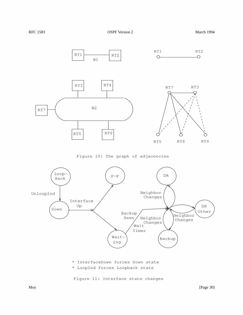
RFC 1583 OSPF Version 2 March 1994
NeighborChanges
UnloopInd
* LoopInd forces Loopback state
Figure 10: The graph of adjacencies
RT1 RT2
RT3 RT4
RT5 RT6
RT7
RT1 RT2
RT3
RT4RT5 RT6
RT7
N1
N2
Figure 11: Interface state changes
Backup
OtherDR
DR
ingWait-
BackLoop-
P-P
DownUp
WaitTimer
Interface
BackupSeen
NeighborChanges
NeighborChanges
* InterfaceDown forces Down state
Moy [Page 30]
RFC 1583 OSPF Version 2 March 1994
8.1 Sending protocol packets
When a router sends a routing protocol packet, it fills in the fields of the standard OSPF packet header as follows.For more details on the header format consult Section A.3.1:
Version # Set to 2, the version number of the protocol as documented in this specification.
Packet type The type of OSPF packet, such as Link state Update or Hello Packet.
Packet length The length of the entire OSPF packet in bytes, including the standard OSPF packet header.
Router ID The identity of the router itself (who is originating the packet).
Area ID The OSPF area that the packet is being sent into.
Checksum The standard IP 16-bit one’s complement checksum of the entire OSPF packet, excluding the 64-bitauthentication field. This checksum should be calculated before handing the packet to the appropriateauthentication procedure.
AuType and Authentication Each OSPF packet exchange is authenticated. Authentication types are assigned bythe protocol and documented in Appendix D. A different authentication scheme can be used for eachOSPF area. The 64-bit authentication field is set by the appropriate authentication procedure(determined by AuType). This procedure should be the last called when forming the packet to be sent.The setting of the authentication field is determined by the packet contents and the authentication key(which is configurable on a per-interface basis).
The IP destination address for the packet is selected as follows. On physical point-to-point networks, the IPdestination is always set to the address AllSPFRouters. On all other network types (including virtual links), themajority of OSPF packets are sent as unicasts, i.e., sent directly to the other end of the adjacency. In this case, the IPdestination is just theNeighbor IP addressassociated with the other end of the adjacency (see Section 10). The onlypackets not sent as unicasts are on broadcast networks; on these networks Hello packets are sent to the multicastdestination AllSPFRouters, the Designated Router and its Backup send both Link State Update Packets and LinkState Acknowledgment Packets to the multicast address AllSPFRouters, while all other routers send both their LinkState Update and Link State Acknowledgment Packets to the multicast address AllDRouters.
Retransmissions of Link State Update packets are ALWAYS sent as unicasts.
The IP source address should be set to the IP address of the sending interface. Interfaces to unnumberedpoint-to-point networks have no associated IP address. On these interfaces, the IP source should be set to any of theother IP addresses belonging to the router. For this reason, there must be at least one IP address assigned to therouter.2 Note that, for most purposes, virtual links act precisely the same as unnumbered point-to-point networks.However, each virtual link does have anIP interface address(discovered during the routing table build process)which is used as the IP source when sending packets over the virtual link.
For more information on the format of specific OSPF packet types, consult the sections listed in Table 10.
2It is possible for all of a router’s interfaces to be unnumbered point-to-point links. In this case, an IP address must be assigned to the router.This address will then be advertised in the router’s router links advertisement as a host route.
Moy [Page 31]
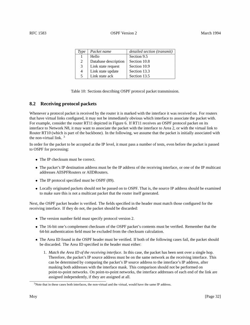
RFC 1583 OSPF Version 2 March 1994
Type Packet name detailed section (transmit)1 Hello Section 9.52 Database description Section 10.83 Link state request Section 10.94 Link state update Section 13.35 Link state ack Section 13.5
Table 10: Sections describing OSPF protocol packet transmission.
8.2 Receiving protocol packets
Whenever a protocol packet is received by the router it is marked with the interface it was received on. For routersthat have virtual links configured, it may not be immediately obvious which interface to associate the packet with.For example, consider the router RT11 depicted in Figure 6. If RT11 receives an OSPF protocol packet on itsinterface to Network N8, it may want to associate the packet with the interface to Area 2, or with the virtual link toRouter RT10 (which is part of the backbone). In the following, we assume that the packet is initially associated withthe non-virtual link.3
In order for the packet to be accepted at the IP level, it must pass a number of tests, even before the packet is passedto OSPF for processing:
� The IP checksum must be correct.
� The packet’s IP destination address must be the IP address of the receiving interface, or one of the IP multicastaddresses AllSPFRouters or AllDRouters.
� The IP protocol specified must be OSPF (89).
� Locally originated packets should not be passed on to OSPF. That is, the source IP address should be examinedto make sure this is not a multicast packet that the router itself generated.
Next, the OSPF packet header is verified. The fields specified in the header must match those configured for thereceiving interface. If they do not, the packet should be discarded:
� The version number field must specify protocol version 2.
� The 16-bit one’s complement checksum of the OSPF packet’s contents must be verified. Remember that the64-bit authentication field must be excluded from the checksum calculation.
� The Area ID found in the OSPF header must be verified. If both of the following cases fail, the packet shouldbe discarded. The Area ID specified in the header must either:
1. Match the Area ID of the receiving interface. In this case, the packet has been sent over a single hop.Therefore, the packet’s IP source address must be on the same network as the receiving interface. Thiscan be determined by comparing the packet’s IP source address to the interface’s IP address, aftermasking both addresses with the interface mask. This comparison should not be performed onpoint-to-point networks. On point-to-point networks, the interface addresses of each end of the link areassigned independently, if they are assigned at all.
3Note that in these cases both interfaces, the non-virtual and the virtual, would have the same IP address.
Moy [Page 32]
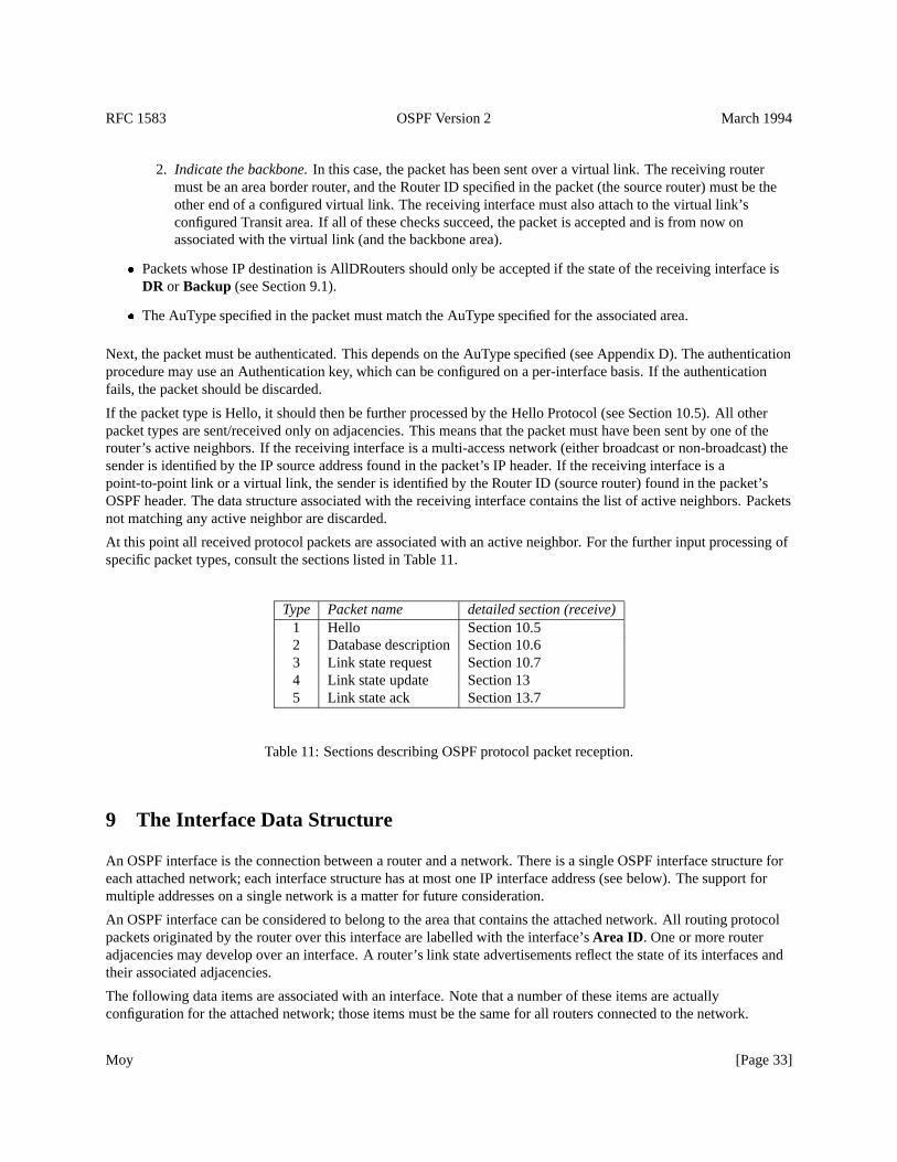
RFC 1583 OSPF Version 2 March 1994
2. Indicate the backbone.In this case, the packet has been sent over a virtual link. The receiving routermust be an area border router, and the Router ID specified in the packet (the source router) must be theother end of a configured virtual link. The receiving interface must also attach to the virtual link’sconfigured Transit area. If all of these checks succeed, the packet is accepted and is from now onassociated with the virtual link (and the backbone area).
� Packets whose IP destination is AllDRouters should only be accepted if the state of the receiving interface isDR or Backup (see Section 9.1).
� The AuType specified in the packet must match the AuType specified for the associated area.
Next, the packet must be authenticated. This depends on the AuType specified (see Appendix D). The authenticationprocedure may use an Authentication key, which can be configured on a per-interface basis. If the authenticationfails, the packet should be discarded.
If the packet type is Hello, it should then be further processed by the Hello Protocol (see Section 10.5). All otherpacket types are sent/received only on adjacencies. This means that the packet must have been sent by one of therouter’s active neighbors. If the receiving interface is a multi-access network (either broadcast or non-broadcast) thesender is identified by the IP source address found in the packet’s IP header. If the receiving interface is apoint-to-point link or a virtual link, the sender is identified by the Router ID (source router) found in the packet’sOSPF header. The data structure associated with the receiving interface contains the list of active neighbors. Packetsnot matching any active neighbor are discarded.
At this point all received protocol packets are associated with an active neighbor. For the further input processing ofspecific packet types, consult the sections listed in Table 11.
Type Packet name detailed section (receive)1 Hello Section 10.52 Database description Section 10.63 Link state request Section 10.74 Link state update Section 135 Link state ack Section 13.7
Table 11: Sections describing OSPF protocol packet reception.
9 The Interface Data Structure
An OSPF interface is the connection between a router and a network. There is a single OSPF interface structure foreach attached network; each interface structure has at most one IP interface address (see below). The support formultiple addresses on a single network is a matter for future consideration.
An OSPF interface can be considered to belong to the area that contains the attached network. All routing protocolpackets originated by the router over this interface are labelled with the interface’sArea ID . One or more routeradjacencies may develop over an interface. A router’s link state advertisements reflect the state of its interfaces andtheir associated adjacencies.
The following data items are associated with an interface. Note that a number of these items are actuallyconfiguration for the attached network; those items must be the same for all routers connected to the network.
Moy [Page 33]
RFC 1583 OSPF Version 2 March 1994
Type The kind of network to which the interface attaches. Its value is either broadcast, non-broadcast yet stillmulti-access, point-to-point or virtual link.
State The functional level of an interface. State determines whether or not full adjacencies are allowed to form overthe interface. State is also reflected in the router’s link state advertisements.
IP interface address The IP address associated with the interface. This appears as the IP source address in allrouting protocol packets originated over this interface. Interfaces to unnumbered point-to-point networks donot have an associated IP address.
IP interface mask Also referred to as the subnet mask, this indicates the portion of the IP interface address thatidentifies the attached network. Masking the IP interface address with the IP interface mask yields the IPnetwork number of the attached network. On point-to-point networks and virtual links, the IP interface mask isnot defined. On these networks, the link itself is not assigned an IP network number, and so the addresses ofeach side of the link are assigned independently, if they are assigned at all.
Area ID The Area ID of the area to which the attached network belongs. All routing protocol packets originatingfrom the interface are labelled with this Area ID.
HelloInterval The length of time, in seconds, between the Hello packets that the router sends on the interface.Advertised in Hello packets sent out this interface.
RouterDeadInterval The number of seconds before the router’s neighbors will declare it down, when they stophearing the router’s Hello Packets. Advertised in Hello packets sent out this interface.
InfTransDelay The estimated number of seconds it takes to transmit a Link State Update Packet over this interface.Link state advertisements contained in the Link State Update packet will have their age incremented by thisamount before transmission. This value should take into account transmission and propagation delays; it mustbe greater than zero.
Router Priority An 8-bit unsigned integer. When two routers attached to a network both attempt to becomeDesignated Router, the one with the highest Router Priority takes precedence. A router whose Router Priorityis set to 0 is ineligible to become Designated Router on the attached network. Advertised in Hello packets sentout this interface.
Hello Timer An interval timer that causes the interface to send a Hello packet. This timer fires every HelloIntervalseconds. Note that on non-broadcast networks a separate Hello packet is sent to each qualified neighbor.
Wait Timer A single shot timer that causes the interface to exit the Waiting state, and as a consequence select aDesignated Router on the network. The length of the timer is RouterDeadInterval seconds.
List of neighboring routers The other routers attached to this network. On multi-access networks, this list isformed by the Hello Protocol. Adjacencies will be formed to some of these neighbors. The set of adjacentneighbors can be determined by an examination of all of the neighbors’ states.
Designated Router The Designated Router selected for the attached network. The Designated Router is selected onall multi-access networks by the Hello Protocol. Two pieces of identification are kept for the DesignatedRouter: its Router ID and its IP interface address on the network. The Designated Router advertises link statefor the network; this network link state advertisement is labelled with the Designated Router’s IP address. TheDesignated Router is initialized to0.0.0.0 , which indicates the lack of a Designated Router.
Backup Designated RouterThe Backup Designated Router is also selected on all multi-access networks by theHello Protocol. All routers on the attached network become adjacent to both the Designated Router and the
Moy [Page 34]
RFC 1583 OSPF Version 2 March 1994
Backup Designated Router. The Backup Designated Router becomes Designated Router when the currentDesignated Router fails. The Backup Designated Router is initialized to0.0.0.0 , indicating the lack of aBackup Designated Router.
Interface output cost(s) The cost of sending a data packet on the interface, expressed in the link state metric. Thisis advertised as the link cost for this interface in the router links advertisement. There may be a separate costfor each IP Type of Service. The cost of an interface must be greater than zero.
RxmtInterval The number of seconds between link state advertisement retransmissions, for adjacencies belongingto this interface. Also used when retransmitting Database Description and Link State Request Packets.
Authentication key This configured data allows the authentication procedure to generate and/or verify theAuthentication field in the OSPF header. The Authentication key can be configured on a per-interface basis.For example, if the AuType indicates simple password, the Authentication key would be a 64-bit password.This key would be inserted directly into the OSPF header when originating routing protocol packets, and therecould be a separate password for each network.
9.1 Interface states
The various states that router interfaces may attain is documented in this section. The states are listed in order ofprogressing functionality. For example, the inoperative state is listed first, followed by a list of intermediate statesbefore the final, fully functional state is achieved. The specification makes use of this ordering by sometimes makingreferences such as “those interfaces in state greater than X”.
Figure 11 shows the graph of interface state changes. The arcs of the graph are labelled with the event causing thestate change. These events are documented in Section 9.2. The interface state machine is described in more detail inSection 9.3.
Down This is the initial interface state. In this state, the lower-level protocols have indicated that the interface isunusable. No protocol traffic at all will be sent or received on such a interface. In this state, interfaceparameters should be set to their initial values. All interface timers should be disabled, and there should be noadjacencies associated with the interface.
Loopback In this state, the router’s interface to the network is looped back. The interface may be looped back inhardware or software. The interface will be unavailable for regular data traffic. However, it may still bedesirable to gain information on the quality of this interface, either through sending ICMP pings to theinterface or through something like a bit error test. For this reason, IP packets may still be addressed to aninterface in Loopback state. To facilitate this, such interfaces are advertised in router links advertisements assingle host routes, whose destination is the IP interface address.4
Waiting In this state, the router is trying to determine the identity of the (Backup) Designated Router for thenetwork. To do this, the router monitors the Hello Packets it receives. The router is not allowed to elect aBackup Designated Router nor a Designated Router until it transitions out of Waiting state. This preventsunnecessary changes of (Backup) Designated Router.
Point-to-point In this state, the interface is operational, and connects either to a physical point-to-point network orto a virtual link. Upon entering this state, the router attempts to form an adjacency with the neighboring router.Hello Packets are sent to the neighbor every HelloInterval seconds.
4Note that no host route is generated for, and no IP packets can be addressed to, interfaces to unnumbered point-to-point networks. This isregardless of such an interface’s state.
Moy [Page 35]
RFC 1583 OSPF Version 2 March 1994
DR Other The interface is to a multi-access network on which another router has been selected to be the DesignatedRouter. In this state, the router itself has not been selected Backup Designated Router either. The router formsadjacencies to both the Designated Router and the Backup Designated Router (if they exist).
Backup In this state, the router itself is the Backup Designated Router on the attached network. It will be promotedto Designated Router when the present Designated Router fails. The router establishes adjacencies to all otherrouters attached to the network. The Backup Designated Router performs slightly different functions duringthe Flooding Procedure, as compared to the Designated Router (see Section 13.3). See Section 7.4 for moredetails on the functions performed by the Backup Designated Router.
DR In this state, this router itself is the Designated Router on the attached network. Adjacencies are established toall other routers attached to the network. The router must also originate a network links advertisement for thenetwork node. The advertisement will contain links to all routers (including the Designated Router itself)attached to the network. See Section 7.3 for more details on the functions performed by the Designated Router.
9.2 Events causing interface state changes
State changes can be effected by a number of events. These events are pictured as the labelled arcs in Figure 11. Thelabel definitions are listed below. For a detailed explanation of the effect of these events on OSPF protocol operation,consult Section 9.3.
InterfaceUp Lower-level protocols have indicated that the network interface is operational. This enables theinterface to transition out of Down state. On virtual links, the interface operational indication is actually aresult of the shortest path calculation (see Section 16.7).
WaitTimer The Wait Timer has fired, indicating the end of the waiting period that is required before electing a(Backup) Designated Router.
BackupSeenThe router has detected the existence or non-existence of a Backup Designated Router for the network.This is done in one of two ways. First, an Hello Packet may be received from a neighbor claiming to be itselfthe Backup Designated Router. Alternatively, an Hello Packet may be received from a neighbor claiming to beitself the Designated Router, and indicating that there is no Backup Designated Router. In either case theremust be bidirectional communication with the neighbor, i.e., the router must also appear in the neighbor’sHello Packet. This event signals an end to the Waiting state.
NeighborChange There has been a change in the set of bidirectional neighbors associated with the interface. The(Backup) Designated Router needs to be recalculated. The following neighbor changes lead to theNeighborChangeevent. For an explanation of neighbor states, see Section 10.1.
� Bidirectional communication has been established to a neighbor. In other words, the state of the neighborhas transitioned to2-Way or higher.
� There is no longer bidirectional communication with a neighbor. In other words, the state of the neighborhas transitioned toInit or lower.
� One of the bidirectional neighbors is newly declaring itself as either Designated Router or BackupDesignated Router. This is detected through examination of that neighbor’s Hello Packets.
� One of the bidirectional neighbors is no longer declaring itself as Designated Router, or is no longerdeclaring itself as Backup Designated Router. This is again detected through examination of thatneighbor’s Hello Packets.
Moy [Page 36]
RFC 1583 OSPF Version 2 March 1994
� The advertisedRouter Priority for a bidirectional neighbor has changed. This is again detected throughexamination of that neighbor’s Hello Packets.
LoopInd An indication has been received that the interface is now looped back to itself. This indication can bereceived either from network management or from the lower level protocols.
UnloopInd An indication has been received that the interface is no longer looped back. As with theLoopInd event,this indication can be received either from network management or from the lower level protocols.
InterfaceDown Lower-level protocols indicate that this interface is no longer functional. No matter what the currentinterface state is, the new interface state will be Down.
9.3 The Interface state machine
A detailed description of the interface state changes follows. Each state change is invoked by an event (Section 9.2).This event may produce different effects, depending on the current state of the interface. For this reason, the statemachine below is organized by current interface state and received event. Each entry in the state machine describesthe resulting new interface state and the required set of additional actions.
When an interface’s state changes, it may be necessary to originate a new router links advertisement. SeeSection 12.4 for more details.
Some of the required actions below involve generating events for the neighbor state machine. For example, when aninterface becomes inoperative, all neighbor connections associated with the interface must be destroyed. For moreinformation on the neighbor state machine, see Section 10.3.
State(s): DownEvent: InterfaceUp
New state: Depends upon action routineAction: Start the intervalHello Timer , enabling the periodic sending of Hello packets out the
interface. If the attached network is a physical point-to-point network or virtual link,the interface state transitions toPoint-to-Point. Else, if the router is not eligible tobecome Designated Router the interface state transitions toDR Other.Otherwise, the attached network is multi-access and the router is eligible to becomeDesignated Router. In this case, in an attempt to discover the attached network’sDesignated Router the interface state is set toWaiting and the single shotWaitTimer is started. If in addition the attached network is non-broadcast, examine theconfigured list of neighbors for this interface and generate the neighbor eventStartfor each neighbor that is also eligible to become Designated Router.
State(s): WaitingEvent: BackupSeen
New state: Depends upon action routine.
Action: Calculate the attached network’s Backup Designated Router and Designated Router,as shown in Section 9.4. As a result of this calculation, the new state of the interfacewill be eitherDR Other, Backup or DR.
State(s): WaitingEvent: WaitTimer
Moy [Page 37]
RFC 1583 OSPF Version 2 March 1994
New state: Depends upon action routine.Action: Calculate the attached network’s Backup Designated Router and Designated Router,
as shown in Section 9.4. As a result of this calculation, the new state of the interfacewill be eitherDR Other, Backup or DR.
State(s): DR Other, Backup or DREvent: NeighborChange
New state: Depends upon action routine.Action: Recalculate the attached network’s Backup Designated Router and Designated
Router, as shown in Section 9.4. As a result of this calculation, the new state of theinterface will be eitherDR Other, Backup or DR.
State(s): Any StateEvent: InterfaceDown
New state: DownAction: All interface variables are reset, and interface timers disabled. Also, all neighbor
connections associated with the interface are destroyed. This is done by generatingthe eventKillNbr on all associated neighbors (see Section 10.2).
State(s): Any StateEvent: LoopInd
New state: LoopbackAction: Since this interface is no longer connected to the attached network the actions
associated with the aboveInterfaceDown event are executed.
State(s): LoopbackEvent: UnloopInd
New state: DownAction: No actions are necessary. For example, the interface variables have already been
reset upon entering theLoopback state. Note that reception of anInterfaceUp eventis necessary before the interface again becomes fully functional.
9.4 Electing the Designated Router
This section describes the algorithm used for calculating a network’s Designated Router and Backup DesignatedRouter. This algorithm is invoked by the Interface state machine. The initial time a router runs the election algorithmfor a network, the network’s Designated Router and Backup Designated Router are initialized to0.0.0.0 . Thisindicates the lack of both a Designated Router and a Backup Designated Router.
The Designated Router election algorithm proceeds as follows: Call the router doing the calculation Router X. Thelist of neighbors attached to the network and having established bidirectional communication with Router X isexamined. This list is precisely the collection of Router X’s neighbors (on this network) whose state is greater thanor equal to2-Way (see Section 10.1). Router X itself is also considered to be on the list. Discard all routers from thelist that are ineligible to become Designated Router. (Routers having Router Priority of 0 are ineligible to becomeDesignated Router.) The following steps are then executed, considering only those routers that remain on the list:
Moy [Page 38]
RFC 1583 OSPF Version 2 March 1994
1. Note the current values for the network’s Designated Router and Backup Designated Router. This is used laterfor comparison purposes.
2. Calculate the new Backup Designated Router for the network as follows. Only those routers on the list thathave not declared themselves to be Designated Router are eligible to become Backup Designated Router. Ifone or more of these routers have declared themselves Backup Designated Router (i.e., they are currentlylisting themselves as Backup Designated Router, but not as Designated Router, in their Hello Packets) the onehaving highest Router Priority is declared to be Backup Designated Router. In case of a tie, the one having thehighest Router ID is chosen. If no routers have declared themselves Backup Designated Router, choose therouter having highest Router Priority, (again excluding those routers who have declared themselves DesignatedRouter), and again use the Router ID to break ties.
3. Calculate the new Designated Router for the network as follows. If one or more of the routers have declaredthemselves Designated Router (i.e., they are currently listing themselves as Designated Router in their HelloPackets) the one having highest Router Priority is declared to be Designated Router. In case of a tie, the onehaving the highest Router ID is chosen. If no routers have declared themselves Designated Router, assign theDesignated Router to be the same as the newly elected Backup Designated Router.
4. If Router X is now newly the Designated Router or newly the Backup Designated Router, or is now no longerthe Designated Router or no longer the Backup Designated Router, repeat steps 2 and 3, and then proceed tostep 5. For example, if Router X is now the Designated Router, when step 2 is repeated X will no longer beeligible for Backup Designated Router election. Among other things, this will ensure that no router willdeclare itself both Backup Designated Router and Designated Router.5
5. As a result of these calculations, the router itself may now be Designated Router or Backup Designated Router.See Sections 7.3 and 7.4 for the additional duties this would entail. The router’s interface state should be setaccordingly. If the router itself is now Designated Router, the new interface state isDR. If the router itself isnow Backup Designated Router, the new interface state isBackup. Otherwise, the new interface state isDROther.
6. If the attached network is non-broadcast, and the router itself has just become either Designated Router orBackup Designated Router, it must start sending Hello Packets to those neighbors that are not eligible tobecome Designated Router (see Section 9.5.1). This is done by invoking the neighbor eventStart for eachneighbor having aRouter Priority of 0.
7. If the above calculations have caused the identity of either the Designated Router or Backup DesignatedRouter to change, the set of adjacencies associated with this interface will need to be modified. Someadjacencies may need to be formed, and others may need to be broken. To accomplish this, invoke the eventAdjOK? on all neighbors whose state is at least2-Way. This will cause their eligibility for adjacency to bereexamined (see Sections 10.3 and 10.4).
The reason behind the election algorithm’s complexity is the desire for an orderly transition from Backup DesignatedRouter to Designated Router, when the current Designated Router fails. This orderly transition is ensured through theintroduction of hysteresis: no new Backup Designated Router can be chosen until the old Backup accepts its newDesignated Router responsibilities.
5It is instructive to see what happens when the Designated Router for the network crashes. Call the Designated Router for the network RT1, andthe Backup Designated Router RT2. If Router RT1 crashes (or maybe its interface to the network dies), the other routers on the network will detectRT1’s absence within RouterDeadInterval seconds. All routers may not detect this at precisely the same time; the routers that detect RT1’s absencebefore RT2 does will, for a time, select RT2 to be both Designated Router and Backup Designated Router. When RT2 detects that RT1 is goneit will move itself to Designated Router. At this time, the remaining router having highest Router Priority will be selected as Backup DesignatedRouter.
Moy [Page 39]
RFC 1583 OSPF Version 2 March 1994
The above procedure may elect the same router to be both Designated Router and Backup Designated Router,although that router will never be the calculating router (Router X) itself. The elected Designated Router may not bethe router having the highest Router Priority, nor will the Backup Designated Router necessarily have the secondhighest Router Priority. If Router X is not itself eligible to become Designated Router, it is possible that neither aBackup Designated Router nor a Designated Router will be selected in the above procedure. Note also that if RouterX is the only attached router that is eligible to become Designated Router, it will select itself as Designated Routerand there will be no Backup Designated Router for the network.
9.5 Sending Hello packets
Hello packets are sent out each functioning router interface. They are used to discover and maintain neighborrelationships.6 On multi-access networks, Hello Packets are also used to elect the Designated Router and BackupDesignated Router, and in that way determine what adjacencies should be formed.
The format of an Hello packet is detailed in Section A.3.2. The Hello Packet contains the router’sRouter Priority(used in choosing the Designated Router), and the interval between Hello Packets sent out the interface(HelloInterval ). The Hello Packet also indicates how often a neighbor must be heard from to remain active(RouterDeadInterval). Both HelloInterval and RouterDeadInterval must be the same for all routers attached to acommon network. The Hello packet also contains the IP address mask of the attached network (Network Mask). Onunnumbered point-to-point networks and on virtual links this field should be set to0.0.0.0 .
The Hello packet’sOptions field describes the router’s optional OSPF capabilities. There are currently two optionalcapabilities defined (see Sections 4.5 and A.2). TheT-bit of theOptions field should be set if the router is capable ofcalculating separate routes for each IP TOS. TheE-bit should be set if and only if the attached area is capable ofprocessing AS external advertisements (i.e., it is not a stub area). If theE-bit is set incorrectly the neighboringrouters will refuse to accept the Hello Packet (see Section 10.5). The rest of the Hello Packet’sOptions field shouldbe set to zero.
In order to ensure two-way communication between adjacent routers, the Hello packet contains the list of all routersfrom which Hello Packets have been seen recently. The Hello packet also contains the router’s current choice forDesignated Router and Backup Designated Router. A value of0.0.0.0 in these fields means that one has not yetbeen selected.
On broadcast networks and physical point-to-point networks, Hello packets are sent every HelloInterval seconds tothe IP multicast address AllSPFRouters. On virtual links, Hello packets are sent as unicasts (addressed directly to theother end of the virtual link) every HelloInterval seconds. On non-broadcast networks, the sending of Hello packetsis more complicated. This will be covered in the next section.
9.5.1 Sending Hello packets on non-broadcast networks
Static configuration information is necessary in order for the Hello Protocol to function on non-broadcast networks(see Section C.5). Every attached router which is eligible to become Designated Router has a configured list of all ofits neighbors on the network. Each listed neighbor is labelled with its Designated Router eligibility.
The interface state must be at leastWaiting for any Hello Packets to be sent. Hello Packets are then sent directly (asunicasts) to some subset of a router’s neighbors. Sometimes an Hello Packet is sent periodically on a timer; at othertimes it is sent as a response to a received Hello Packet. A router’s hello-sending behavior varies depending onwhether the router itself is eligible to become Designated Router.
6On point-to-point networks, the lower level protocols indicate whether the neighbor is up and running. Likewise, existence of the neighboron virtual links is indicated by the routing table calculation. However, in both these cases, the Hello Protocol is still used. This ensures thatcommunication between the neighbors is bidirectional, and that each of the neighbors has a functioning routing protocol layer.
Moy [Page 40]
RFC 1583 OSPF Version 2 March 1994
If the router is eligible to become Designated Router, it must periodically send Hello Packets to all neighbors that arealso eligible. In addition, if the router is itself the Designated Router or Backup Designated Router, it must also sendperiodic Hello Packets to all other neighbors. This means that any two eligible routers are always exchanging HelloPackets, which is necessary for the correct operation of the Designated Router election algorithm. To minimize thenumber of Hello Packets sent, the number of eligible routers on a non-broadcast network should be kept small.
If the router is not eligible to become Designated Router, it must periodically send Hello Packets to both theDesignated Router and the Backup Designated Router (if they exist). It must also send an Hello Packet in reply to anHello Packet received from any eligible neighbor (other than the current Designated Router and Backup DesignatedRouter). This is needed to establish an initial bidirectional relationship with any potential Designated Router.
When sending Hello packets periodically to any neighbor, the interval between Hello Packets is determined by theneighbor’s state. If the neighbor is in stateDown, Hello Packets are sent every PollInterval seconds. Otherwise,Hello Packets are sent every HelloInterval seconds.
10 The Neighbor Data Structure
An OSPF router converses with its neighboring routers. Each separate conversation is described by a “neighbor datastructure”. Each conversation is bound to a particular OSPF router interface, and is identified either by theneighboring router’s OSPF Router ID or by its Neighbor IP address (see below). Thus if the OSPF router and anotherrouter have multiple attached networks in common, multiple conversations ensue, each described by a uniqueneighbor data structure. Each separate conversation is loosely referred to in the text as being a separate “neighbor”.
The neighbor data structure contains all information pertinent to the forming or formed adjacency between the twoneighbors. (However, remember that not all neighbors become adjacent.) An adjacency can be viewed as a highlydeveloped conversation between two routers.
State The functional level of the neighbor conversation. This is described in more detail in Section 10.1.
Inactivity Timer A single shot timer whose firing indicates that no Hello Packet has been seen from this neighborrecently. The length of the timer is RouterDeadInterval seconds.
Master/Slave When the two neighbors are exchanging databases, they form a master/slave relationship. The mastersends the first Database Description Packet, and is the only part that is allowed to retransmit. The slave canonly respond to the master’s Database Description Packets. The master/slave relationship is negotiated in stateExStart.
DD Sequence NumberA 32-bit number identifying individual Database Description packets. When the neighborstate ExStart is entered, the DD sequence number should be set to a value not previously seen by theneighboring router. One possible scheme is to use the machine’s time of day counter. The DD sequencenumber is then incremented by the master with each new Database Description packet sent. The slave’s DDsequence number indicates the last packet received from the master. Only one packet is allowed outstanding ata time.
Neighbor ID The OSPF Router ID of the neighboring router. The Neighbor ID is learned when Hello packets arereceived from the neighbor, or is configured if this is a virtual adjacency (see Section C.4).
Neighbor Priority The Router Priority of the neighboring router. Contained in the neighbor’s Hello packets, thisitem is used when selecting the Designated Router for the attached network.
Moy [Page 41]

RFC 1583 OSPF Version 2 March 1994
Neighbor IP address The IP address of the neighboring router’s interface to the attached network. Used as theDestination IP address when protocol packets are sent as unicasts along this adjacency. Also used in routerlinks advertisements as theLink ID for the attached network if the neighboring router is selected to beDesignated Router (see Section 12.4.1). The Neighbor IP address is learned when Hello packets are receivedfrom the neighbor. For virtual links, the Neighbor IP address is learned during the routing table build process(see Section 15).
Neighbor Options The optional OSPF capabilities supported by the neighbor. Learned during the DatabaseExchange process (see Section 10.6). The neighbor’s optional OSPF capabilities are also listed in its Hellopackets. This enables received Hello Packets to be rejected (i.e., neighbor relationships will not even start toform) if there is a mismatch in certain crucial OSPF capabilities (see Section 10.5). The optional OSPFcapabilities are documented in Section 4.5.
Neighbor’s Designated RouterThe neighbor’s idea of the Designated Router. If this is the neighbor itself, this isimportant in the local calculation of the Designated Router. Defined only on multi-access networks.
Neighbor’s Backup Designated RouterThe neighbor’s idea of the Backup Designated Router. If this is theneighbor itself, this is important in the local calculation of the Backup Designated Router. Defined only onmulti-access networks.
The next set of variables are lists of link state advertisements. These lists describe subsets of the area topologicaldatabase. There can be five distinct types of link state advertisements in an area topological database: router links,network links, and Type 3 and 4 summary links (all stored in the area data structure), and AS external links (stored inthe global data structure).
Link state retransmission list The list of link state advertisements that have been flooded but not acknowledged onthis adjacency. These will be retransmitted at intervals until they are acknowledged, or until the adjacency isdestroyed.
Database summary list The complete list of link state advertisements that make up the area topological database, atthe moment the neighbor goes into Database Exchange state. This list is sent to the neighbor in DatabaseDescription packets.
Link state request list The list of link state advertisements that need to be received from this neighbor in order tosynchronize the two neighbors’ topological databases. This list is created as Database Description packets arereceived, and is then sent to the neighbor in Link State Request packets. The list is depleted as appropriateLink State Update packets are received.
10.1 Neighbor states
The state of a neighbor (really, the state of a conversation being held with a neighboring router) is documented in thefollowing sections. The states are listed in order of progressing functionality. For example, the inoperative state islisted first, followed by a list of intermediate states before the final, fully functional state is achieved. Thespecification makes use of this ordering by sometimes making references such as “those neighbors/adjacencies instate greater than X”. Figures 12 and 13 show the graph of neighbor state changes. The arcs of the graphs arelabelled with the event causing the state change. The neighbor events are documented in Section 10.2.
The graph in Figure 12 shows the state changes effected by the Hello Protocol. The Hello Protocol is responsible forneighbor acquisition and maintenance, and for ensuring two way communication between neighbors.
The graph in Figure 13 shows the forming of an adjacency. Not every two neighboring routers become adjacent (seeSection 10.4). The adjacency starts to form when the neighbor is in stateExStart. After the two routers discover
Moy [Page 42]
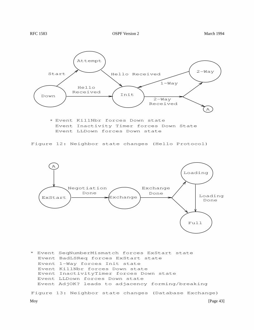
RFC 1583 OSPF Version 2 March 1994
Event BadLSReq forces ExStart state* Event SeqNumberMismatch forces ExStart state
Event AdjOK? leads to adjacency forming/breaking
Event 1-Way forces Init state
Event LLDown forces Down state
Event LLDown forces Down state
Event KillNbr forces Down state
Event KillNbr forces Down stateEvent InactivityTimer forces Down state
DoneLoading
DoneExchangeNegotiation
Done
Figure 13: Neighbor state changes (Database Exchange)
Loading
Full
ExStart Exchange
Event Inactivity Timer forces Down State
Received2-Way
ReceivedHello
2-Way
InitDown
1-Way
Figure 12: Neighbor state changes (Hello Protocol)
Attempt
Hello ReceivedStart
*
A
A
Moy [Page 43]
RFC 1583 OSPF Version 2 March 1994
their master/slave status, the state transitions toExchange. At this point the neighbor starts to be used in the floodingprocedure, and the two neighboring routers begin synchronizing their databases. When this synchronization isfinished, the neighbor is in stateFull and we say that the two routers are fully adjacent. At this point the adjacency islisted in link state advertisements.
For a more detailed description of neighbor state changes, together with the additional actions involved in eachchange, see Section 10.3.
Down This is the initial state of a neighbor conversation. It indicates that there has been no recent informationreceived from the neighbor. On non-broadcast networks, Hello packets may still be sent to “Down” neighbors,although at a reduced frequency (see Section 9.5.1).
Attempt This state is only valid for neighbors attached to non-broadcast networks. It indicates that no recentinformation has been received from the neighbor, but that a more concerted effort should be made to contact theneighbor. This is done by sending the neighbor Hello packets at intervals of HelloInterval (see Section 9.5.1).
Init In this state, an Hello packet has recently been seen from the neighbor. However, bidirectional communicationhas not yet been established with the neighbor (i.e., the router itself did not appear in the neighbor’s Hellopacket). All neighbors in this state (or higher) are listed in the Hello packets sent from the associated interface.
2-Way In this state, communication between the two routers is bidirectional. This has been assured by the operationof the Hello Protocol. This is the most advanced state short of beginning adjacency establishment. The(Backup) Designated Router is selected from the set of neighbors in state2-Way or greater.
ExStart This is the first step in creating an adjacency between the two neighboring routers. The goal of this step isto decide which router is the master, and to decide upon the initial DD sequence number. Neighborconversations in this state or greater are called adjacencies.
Exchange In this state the router is describing its entire link state database by sending Database Description packetsto the neighbor. Each Database Description Packet has a DD sequence number, and is explicitlyacknowledged. Only one Database Description Packet is allowed outstanding at any one time. In this state,Link State Request Packets may also be sent asking for the neighbor’s more recent advertisements. Alladjacencies inExchangestate or greater are used by the flooding procedure. In fact, these adjacencies arefully capable of transmitting and receiving all types of OSPF routing protocol packets.
Loading In this state, Link State Request packets are sent to the neighbor asking for the more recent advertisementsthat have been discovered (but not yet received) in theExchangestate.
Full In this state, the neighboring routers are fully adjacent. These adjacencies will now appear in router links andnetwork links advertisements.
10.2 Events causing neighbor state changes
State changes can be effected by a number of events. These events are shown in the labels of the arcs in Figures 12and 13. The label definitions are as follows:
HelloReceived A Hello packet has been received from a neighbor.
Start This is an indication that Hello Packets should now be sent to the neighbor at intervals of HelloIntervalseconds. This event is generated only for neighbors associated with non-broadcast networks.
2-WayReceivedBidirectional communication has been realized between the two neighboring routers. This isindicated by this router seeing itself in the other’s Hello packet.
Moy [Page 44]
RFC 1583 OSPF Version 2 March 1994
NegotiationDone The Master/Slave relationship has been negotiated, and DD sequence numbers have beenexchanged. This signals the start of the sending/receiving of Database Description packets. For moreinformation on the generation of this event, consult Section 10.8.
ExchangeDoneBoth routers have successfully transmitted a full sequence of Database Description packets. Eachrouter now knows what parts of its link state database are out of date. For more information on the generationof this event, consult Section 10.8.
BadLSReq A Link State Request has been received for a link state advertisement not contained in the database.This indicates an error in the Database Exchange process.
Loading Done Link State Updates have been received for all out-of-date portions of the database. This is indicatedby theLink state request list becoming empty after the Database Exchange process has completed.
AdjOK? A decision must be made (again) as to whether an adjacency should be established/maintained with theneighbor. This event will start some adjacencies forming, and destroy others.
The following events cause well developed neighbors to revert to lesser states. Unlike the above events, these eventsmay occur when the neighbor conversation is in any of a number of states.
SeqNumberMismatch A Database Description packet has been received that either a) has an unexpected DDsequence number, b) unexpectedly has the Init bit set or c) has an Options field differing from the last Optionsfield received in a Database Description packet. Any of these conditions indicate that some error has occurredduring adjacency establishment.
1-Way An Hello packet has been received from the neighbor, in which this router is not mentioned. This indicatesthat communication with the neighbor is not bidirectional.
KillNbr This is an indication that all communication with the neighbor is now impossible, forcing the neighbor torevert to Down state.
InactivityTimer The inactivity Timer has fired. This means that no Hello packets have been seen recently from theneighbor. The neighbor reverts to Down state.
LLDown This is an indication from the lower level protocols that the neighbor is now unreachable. For example, onan X.25 network this could be indicated by an X.25 clear indication with appropriate cause and diagnosticfields. This event forces the neighbor into Down state.
10.3 The Neighbor state machine
A detailed description of the neighbor state changes follows. Each state change is invoked by an event(Section 10.2). This event may produce different effects, depending on the current state of the neighbor. For thisreason, the state machine below is organized by current neighbor state and received event. Each entry in the statemachine describes the resulting new neighbor state and the required set of additional actions.
When a neighbor’s state changes, it may be necessary to rerun the Designated Router election algorithm. This isdetermined by whether the interfaceNeighborChangeevent is generated (see Section 9.2). Also, if the Interface isin DR state (the router is itself Designated Router), changes in neighbor state may cause a new network linksadvertisement to be originated (see Section 12.4).
When the neighbor state machine needs to invoke the interface state machine, it should be done as ascheduledtask(see Section 4.4). This simplifies things, by ensuring that neither state machine will beexecutedrecursively.
Moy [Page 45]

RFC 1583 OSPF Version 2 March 1994
State(s): DownEvent: Start
New state: AttemptAction: Send an Hello Packet to the neighbor (this neighbor is always associated with a
non-broadcast network) and start the Inactivity Timer for the neighbor. The timer’slater firing would indicate that communication with the neighbor was not attained.
State(s): AttemptEvent: HelloReceived
New state: InitAction: Restart the Inactivity Timer for the neighbor, since the neighbor has now been heard
from.
State(s): DownEvent: HelloReceived
New state: InitAction: Start the Inactivity Timer for the neighbor. The timer’s later firing would indicate that
the neighbor is dead.
State(s): Init or greaterEvent: HelloReceived
New state: No state change.Action: Restart the Inactivity Timer for the neighbor, since the neighbor has again been heard
from.
State(s): InitEvent: 2-WayReceived
New state: Depends upon action routine.Action: Determine whether an adjacency should be established with the neighbor (see
Section 10.4). If not, the new neighbor state is2-Way.
Otherwise (an adjacency should be established) the neighbor state transitions toExStart. Upon entering this state, the router increments the DD sequence number forthis neighbor. If this is the first time that an adjacency has been attempted, the DDsequence number should be assigned some unique value (like the time of day clock).It then declares itself master (sets the master/slave bit to master), and starts sendingDatabase Description Packets, with the initialize (I), more (M) and master (MS) bitsset. This Database Description Packet should be otherwise empty. This DatabaseDescription Packet should be retransmitted at intervals of RxmtInterval until the nextstate is entered (see Section 10.8).
State(s): ExStartEvent: NegotiationDone
New state: ExchangeAction: The router must list the contents of its entire area link state database in the neighbor
Database summary list. The area link state database consists of the router links,
Moy [Page 46]
RFC 1583 OSPF Version 2 March 1994
network links and summary links contained in the area structure, along with the ASexternal links contained in the global structure. AS external link advertisements areomitted from a virtual neighbor’sDatabase summary list. AS externaladvertisements are omitted from theDatabase summary listif the area has beenconfigured as a stub (see Section 3.6). Advertisements whose age is equal to MaxAgeare instead added to the neighbor’sLink state retransmission list. A summary oftheDatabase summary listwill be sent to the neighbor in Database Descriptionpackets. Each Database Description Packet has a DD sequence number, and isexplicitly acknowledged. Only one Database Description Packet is allowedoutstanding at any one time. For more detail on the sending and receiving ofDatabase Description packets, see Sections 10.8 and 10.6.
State(s): ExchangeEvent: ExchangeDone
New state: Depends upon action routine.Action: If the neighborLink state request list is empty, the new neighbor state isFull . No
other action is required. This is an adjacency’s final state.Otherwise, the new neighbor state isLoading. Start (or continue) sending Link StateRequest packets to the neighbor (see Section 10.9). These are requests for theneighbor’s more recent advertisements (which were discovered but not yet receivedin theExchangestate). These advertisements are listed in theLink state request listassociated with the neighbor.
State(s): LoadingEvent: Loading Done
New state: FullAction: No action required. This is an adjacency’s final state.
State(s): 2-WayEvent: AdjOK?
New state: Depends upon action routine.Action: Determine whether an adjacency should be formed with the neighboring router (see
Section 10.4). If not, the neighbor state remains at2-Way. Otherwise, transition theneighbor state toExStart and perform the actions associated with the above statemachine entry for stateInit and event2-WayReceived.
State(s): ExStart or greaterEvent: AdjOK?
New state: Depends upon action routine.Action: Determine whether the neighboring router should still be adjacent. If yes, there is no
state change and no further action is necessary.Otherwise, the (possibly partially formed) adjacency must be destroyed. Theneighbor state transitions to2-Way. TheLink state retransmission list, Databasesummary list andLink state request list are cleared of link state advertisements.
State(s): Exchangeor greater
Moy [Page 47]
RFC 1583 OSPF Version 2 March 1994
Event: SeqNumberMismatchNew state: ExStart
Action: The (possibly partially formed) adjacency is torn down, and then an attempt is madeat reestablishment. The neighbor state first transitions toExStart. TheLink stateretransmission list, Database summary listandLink state request list are clearedof link state advertisements. Then the router increments the DD sequence number forthis neighbor, declares itself master (sets the master/slave bit to master), and startssending Database Description Packets, with the initialize (I), more (M) and master(MS) bits set. This Database Description Packet should be otherwise empty (seeSection 10.8).
State(s): Exchangeor greaterEvent: BadLSReq
New state: ExStartAction: The action for eventBadLSReq is exactly the same as for the neighbor event
SeqNumberMismatch. The (possibly partially formed) adjacency is torn down, andthen an attempt is made at reestablishment. For more information, see the neighborstate machine entry that is invoked when eventSeqNumberMismatchis generatedin stateExchangeor greater.
State(s): Any stateEvent: KillNbr
New state: DownAction: TheLink state retransmission list, Database summary listandLink state request
list are cleared of link state advertisements. Also, the Inactivity Timer is disabled.
State(s): Any stateEvent: LLDown
New state: DownAction: TheLink state retransmission list, Database summary listandLink state request
list are cleared of link state advertisements. Also, the Inactivity Timer is disabled.
State(s): Any stateEvent: InactivityTimer
New state: DownAction: TheLink state retransmission list, Database summary listandLink state request
list are cleared of link state advertisements.
State(s): 2-Way or greaterEvent: 1-WayReceived
New state: InitAction: TheLink state retransmission list, Database summary listandLink state request
list are cleared of link state advertisements.
State(s): 2-Way or greater
Moy [Page 48]
RFC 1583 OSPF Version 2 March 1994
Event: 2-Way receivedNew state: No state change.
Action: No action required.
State(s): InitEvent: 1-WayReceived
New state: No state change.Action: No action required.
10.4 Whether to become adjacent
Adjacencies are established with some subset of the router’s neighbors. Routers connected by point-to-pointnetworks and virtual links always become adjacent. On multi-access networks, all routers become adjacent to boththe Designated Router and the Backup Designated Router.
The adjacency-forming decision occurs in two places in the neighbor state machine. First, when bidirectionalcommunication is initially established with the neighbor, and secondly, when the identity of the attached network’s(Backup) Designated Router changes. If the decision is made to not attempt an adjacency, the state of the neighborcommunication stops at2-Way.
An adjacency should be established with a bidirectional neighbor when at least one of the following conditions holds:
- The underlying network type is point-to-point- The underlying network type is virtual link- The router itself is the Designated Router- The router itself is the Backup Designated Router- The neighboring router is the Designated Router- The neighboring router is the Backup Designated Router
10.5 Receiving Hello Packets
This section explains the detailed processing of a received Hello Packet. (See Section A.3.2 for the format of Hellopackets.) The generic input processing of OSPF packets will have checked the validity of the IP header and theOSPF packet header. Next, the values of theNetwork Mask, HelloInterval , andRouterDeadInterval fields in thereceived Hello packet must be checked against the values configured for the receiving interface. Any mismatchcauses processing to stop and the packet to be dropped. In other words, the above fields are really describing theattached network’s configuration. However, there is one exception to the above rule: on point-to-point networks andon virtual links, theNetwork Mask in the received Hello Packet should be ignored.
The receiving interface attaches to a single OSPF area (this could be the backbone). The setting of theE-bit found inthe Hello Packet’s Options field must match this area’s ExternalRoutingCapability. If AS external advertisements arenot flooded into/throughout the area (i.e, the area is a “stub”) theE-bit must be clear in received Hello Packets,otherwise theE-bit must be set. A mismatch causes processing to stop and the packet to be dropped. The setting ofthe rest of the bits in the Hello Packet’s Options field should be ignored.
At this point, an attempt is made to match the source of the Hello Packet to one of the receiving interface’sneighbors. If the receiving interface is a multi-access network (either broadcast or non-broadcast) the source isidentified by the IP source address found in the Hello’s IP header. If the receiving interface is a point-to-point link ora virtual link, the source is identified by the Router ID found in the Hello’s OSPF packet header. The interface’s
Moy [Page 49]
RFC 1583 OSPF Version 2 March 1994
current list of neighbors is contained in the interface’s data structure. If a matching neighbor structure cannot befound, (i.e., this is the first time the neighbor has been detected), one is created. The initial state of a newly createdneighbor is set toDown.
When receiving an Hello Packet from a neighbor on a multi-access network (broadcast or non-broadcast), set theneighbor structure’s Neighbor ID equal to the Router ID found in the packet’s OSPF header. When receiving anHello on a point-to-point network (but not on a virtual link) set the neighbor structure’s Neighbor IP address to thepacket’s IP source address.
Now the rest of the Hello Packet is examined, generating events to be given to the neighbor and interface statemachines. These state machines are specified either to beexecutedor scheduled(see Section 4.4). For example, byspecifying below that the neighbor state machine beexecutedin line, several neighbor state transitions may beeffected by a single received Hello:
� Each Hello Packet causes the neighbor state machine to beexecutedwith the eventHelloReceived.
� Then the list of neighbors contained in the Hello Packet is examined. If the router itself appears in this list, theneighbor state machine should beexecutedwith the event2-WayReceived. Otherwise, the neighbor statemachine should be executed with the event1-WayReceived, and the processing of the packet stops.
� Next, the Hello Packet’s Router Priority field is examined. If this field is different than the one previouslyreceived from the neighbor, the receiving interface’s state machine isscheduledwith the eventNeighborChange. In any case, the Router Priority field in the neighbor data structure should be updatedaccordingly.
� Next the Designated Router field in the Hello Packet is examined. If the neighbor is both declaring itself to beDesignated Router (Designated Router field = Neighbor IP address) and the Backup Designated Router field inthe packet is equal to0.0.0.0 and the receiving interface is in stateWaiting , the receiving interface’s statemachine isscheduledwith the eventBackupSeen. Otherwise, if the neighbor is declaring itself to beDesignated Router and it had not previously, or the neighbor is not declaring itself Designated Router where ithad previously, the receiving interface’s state machine isscheduledwith the eventNeighborChange. In anycase, the Neighbor’s Designated Router item in the neighbor structure is updated accordingly.
� Finally, the Backup Designated Router field in the Hello Packet is examined. If the neighbor is declaring itselfto be Backup Designated Router (Backup Designated Router field = Neighbor IP address) and the receivinginterface is in stateWaiting , the receiving interface’s state machine isscheduledwith the eventBackupSeen.Otherwise, if the neighbor is declaring itself to be Backup Designated Router and it had not previously, or theneighbor is not declaring itself Backup Designated Router where it had previously, the receiving interface’sstate machine isscheduledwith the eventNeighborChange. In any case, the Neighbor’s Backup DesignatedRouter item in the neighbor structure is updated accordingly.
On non-broadcast multi-access networks, receipt of an Hello Packet may also cause an Hello Packet to be sent backto the neighbor in response. See Section 9.5.1 for more details.
10.6 Receiving Database Description Packets
This section explains the detailed processing of a received Database Description Packet. The incoming DatabaseDescription Packet has already been associated with a neighbor and receiving interface by the generic input packetprocessing (Section 8.2). The further processing of the Database Description Packet depends on the neighbor state.If the neighbor’s state isDown or Attempt the packet should be ignored. Otherwise, if the state is:
Moy [Page 50]
RFC 1583 OSPF Version 2 March 1994
Init The neighbor state machine should beexecutedwith the event2-WayReceived. This causes an immediate statechange to either state2-Way or stateExStart. If the new state is ExStart, the processing of the current packetshould then continue in this new state by falling through to case ExStart below.
2-Way The packet should be ignored. Database Description Packets are used only for the purpose of bringing upadjacencies.7
ExStart If the received packet matches one of the following cases, then the neighbor state machine should beexecutedwith the eventNegotiationDone(causing the state to transition toExchange), the packet’s Optionsfield should be recorded in the neighbor structure’sNeighbor Options field and the packet should be acceptedas next in sequence and processed further (see below). Otherwise, the packet should be ignored.
� The initialize(I), more (M) and master(MS) bits are set, the contents of the packet are empty, and theneighbor’s Router ID is larger than the router’s own. In this case the router is now Slave. Set themaster/slave bit to slave, and set the DD sequence number to that specified by the master.
� The initialize(I) and master(MS) bits are off, the packet’s DD sequence number equals the router’s ownDD sequence number (indicating acknowledgment) and the neighbor’s Router ID is smaller than therouter’s own. In this case the router is Master.
Exchange If the state of the MS-bit is inconsistent with the master/slave state of the connection, generate theneighbor eventSeqNumberMismatchand stop processing the packet. Otherwise:
� If the initialize(I) bit is set, generate the neighbor eventSeqNumberMismatchand stop processing thepacket.
� If the packet’s Options field indicates a different set of optional OSPF capabilities than were previouslyreceived from the neighbor (recorded in theNeighbor Options field of the neighbor structure), generatethe neighbor eventSeqNumberMismatchand stop processing the packet.
� If the router is master, and the packet’s DD sequence number equals the router’s own DD sequencenumber (this packet is the next in sequence) the packet should be accepted and its contents processed(below).
� If the router is master, and the packet’s DD sequence number is one less than the router’s DD sequencenumber, the packet is a duplicate. Duplicates should be discarded by the master.
� If the router is slave, and the packet’s DD sequence number is one more than the router’s own DDsequence number (this packet is the next in sequence) the packet should be accepted and its contentsprocessed (below).
� If the router is slave, and the packet’s DD sequence number is equal to the router’s DD sequence number,the packet is a duplicate. The slave must respond to duplicates by repeating the last Database Descriptionpacket that it had sent.
� Else, generate the neighbor eventSeqNumberMismatchand stop processing the packet.
Loading or Full In this state, the router has sent and received an entire sequence of Database Description Packets.The only packets received should be duplicates (see above). In particular, the packet’s Options field shouldmatch the set of optional OSPF capabilities previously indicated by the neighbor (stored in the neighborstructure’sNeighbor Options field). Any other packets received, including the reception of a packet with theInitialize(I) bit set, should generate the neighbor eventSeqNumberMismatch. 8 Duplicates should be
7When the identity of the Designated Router is changing, it may be quite common for a neighbor in this state to send the router a DatabaseDescription packet; this means that there is some momentary disagreement on the Designated Router’s identity.
8Note that it is possible for a router to resynchronize any of its fully established adjacencies by setting the adjacency’s state back toExStart.This will cause the other end of the adjacency to process aSeqNumberMismatchevent, and therefore to also go back toExStart state.
Moy [Page 51]
RFC 1583 OSPF Version 2 March 1994
discarded by the master. The slave must respond to duplicates by repeating the last Database Descriptionpacket that it had sent.
When the router accepts a received Database Description Packet as the next in sequence the packet contents areprocessed as follows. For each link state advertisement listed, the advertisement’s LS type is checked for validity. IftheLS type is unknown (e.g., not one of the LS types 1-5 defined by this specification), or if this is a AS externaladvertisement (LS type= 5) and the neighbor is associated with a stub area, generate the neighbor eventSeqNumberMismatchand stop processing the packet. Otherwise, the router looks up the advertisement in itsdatabase to see whether it also has an instance of the link state advertisement. If it does not, or if the database copy isless recent (see Section 13.1), the link state advertisement is put on theLink state request list so that it can berequested (immediately or at some later time) in Link State Request Packets.
When the router accepts a received Database Description Packet as the next in sequence, it also performs thefollowing actions, depending on whether it is master or slave:
Master Increments the DD sequence number. If the router has already sent its entire sequence of DatabaseDescription Packets, and the just accepted packet has the more bit (M) set to 0, the neighbor eventExchangeDoneis generated. Otherwise, it should send a new Database Description to the slave.
Slave Sets the DD sequence number to the DD sequence number appearing in the received packet. The slave mustsend a Database Description Packet in reply. If the received packet has the more bit (M) set to 0, and thepacket to be sent by the slave will also have the M-bit set to 0, the neighbor eventExchangeDoneisgenerated. Note that the slave always generates this event before the master.
10.7 Receiving Link State Request Packets
This section explains the detailed processing of received Link State Request packets. Received Link State RequestPackets specify a list of link state advertisements that the neighbor wishes to receive. Link State Request Packetsshould be accepted when the neighbor is in statesExchange, Loading, or Full . In all other states Link State RequestPackets should be ignored.
Each link state advertisement specified in the Link State Request packet should be located in the router’s database,and copied into Link State Update packets for transmission to the neighbor. These link state advertisements shouldNOT be placed on theLink state retransmission list for the neighbor. If a link state advertisement cannot be foundin the database, something has gone wrong with the Database Exchange process, and neighbor eventBadLSReqshould be generated.
10.8 Sending Database Description Packets
This section describes how Database Description Packets are sent to a neighbor. The router’s optional OSPFcapabilities (see Section 4.5) are transmitted to the neighbor in theOptions field of the Database Description packet.The router should maintain the same set of optional capabilities throughout the Database Exchange and floodingprocedures. If for some reason the router’s optional capabilities change, the Database Exchange procedure should berestarted by reverting to neighbor stateExStart. There are currently two optional capabilities defined. TheT-bitshould be set if and only if the router is capable of calculating separate routes for each IP TOS. TheE-bit should beset if and only if the attached network belongs to a non-stub area. The rest of theOptions field should be set to zero.
The sending of Database Description packets depends on the neighbor’s state. In stateExStart the router sendsempty Database Description packets, with the initialize (I), more (M) and master (MS) bits set. These packets areretransmitted every RxmtInterval seconds.
Moy [Page 52]
RFC 1583 OSPF Version 2 March 1994
In stateExchangethe Database Description Packets actually contain summaries of the link state informationcontained in the router’s database. Each link state advertisement in the area’s topological database (at the time theneighbor transitions intoExchangestate) is listed in the neighborDatabase summary list. When a new DatabaseDescription Packet is to be sent, the packet’s DD sequence number is incremented, and the (new) top of theDatabase summary listis described by the packet. Items are removed from theDatabase summary listwhen theprevious packet is acknowledged.
In stateExchange, the determination of when to send a Database Description packet depends on whether the routeris master or slave:
Master Database Description packets are sent when either a) the slave acknowledges the previous DatabaseDescription packet by echoing the DD sequence number or b) RxmtInterval seconds elapse without anacknowledgment, in which case the previous Database Description packet is retransmitted.
Slave Database Description packets are sent only in response to Database Description packets received from themaster. If the Database Description packet received from the master is new, a new Database Descriptionpacket is sent, otherwise the previous Database Description packet is resent.
In statesLoading andFull the slave must resend its last Database Description packet in response to duplicateDatabase Description packets received from the master. For this reason the slave must wait RouterDeadIntervalseconds before freeing the last Database Description packet. Reception of a Database Description packet from themaster after this interval will generate aSeqNumberMismatchneighbor event.
10.9 Sending Link State Request Packets
In neighbor statesExchangeor Loading, theLink state request list contains a list of those link state advertisementsthat need to be obtained from the neighbor. To request these advertisements, a router sends the neighbor thebeginning of theLink state request list, packaged in a Link State Request packet.
When the neighbor responds to these requests with the proper Link State Update packet(s), theLink state requestlist is truncated and a new Link State Request packet is sent. This process continues until the Link state request listbecomes empty. Unsatisfied Link State Request packets are retransmitted at intervals of RxmtInterval. There shouldbe at most one Link State Request packet outstanding at any one time.
When theLink state request list becomes empty, and the neighbor state isLoading (i.e., a complete sequence ofDatabase Description packets has been sent to and received from the neighbor), theLoading Doneneighbor event isgenerated.
10.10 An Example
Figure 14 shows an example of an adjacency forming. Routers RT1 and RT2 are both connected to a broadcastnetwork. It is assumed that RT2 is the Designated Router for the network, and that RT2 has a higher Router ID thanRouter RT1.
The neighbor state changes realized by each router are listed on the sides of the figure.
At the beginning of Figure 14, Router RT1’s interface to the network becomes operational. It begins sending HelloPackets, although it doesn’t know the identity of the Designated Router or of any other neighboring routers. RouterRT2 hears this hello (moving the neighbor toInit state), and in its next Hello Packet indicates that it is itself theDesignated Router and that it has heard Hello Packets from RT1. This in turn causes RT1 to go to stateExStart, as itstarts to bring up the adjacency.
Moy [Page 53]
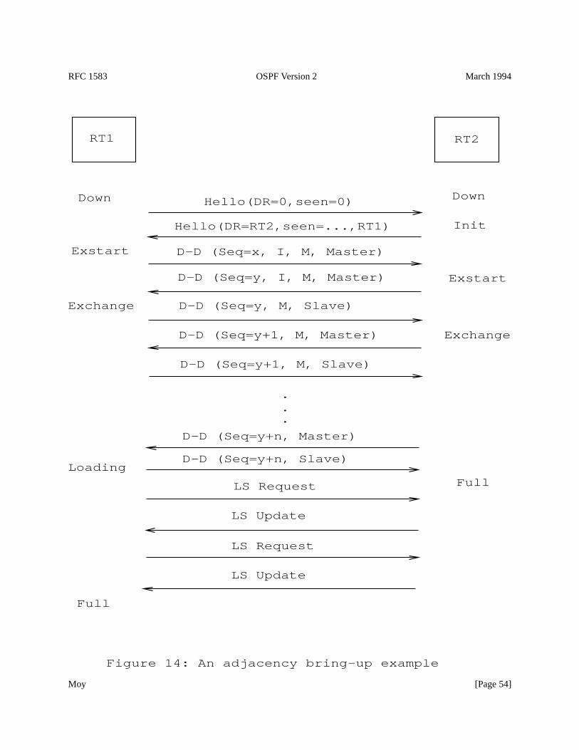
RFC 1583 OSPF Version 2 March 1994
Exchange
Exchange
InitHello(DR=RT2,seen=...,RT1)
Hello(DR=0,seen=0)
Figure 14: An adjacency bring-up example
Exstart
Exstart
DownDown
D-D (Seq=y+1, M, Slave)
D-D (Seq=y+1, M, Master)
D-D (Seq=y, M, Slave)
D-D (Seq=y, I, M, Master)
D-D (Seq=x, I, M, Master)
.
.
.
RT2RT1
Full
FullLoading
LS Update
LS Update
LS Request
LS Request
D-D (Seq=y+n, Slave)
D-D (Seq=y+n, Master)
Moy [Page 54]
RFC 1583 OSPF Version 2 March 1994
RT1 begins by asserting itself as the master. When it sees that RT2 is indeed the master (because of RT2’s higherRouter ID), RT1 transitions to slave state and adopts its neighbor’s DD sequence number. Database Descriptionpackets are then exchanged, with polls coming from the master (RT2) and responses from the slave (RT1). Thissequence of Database Description Packets ends when both the poll and associated response has the M-bit off.
In this example, it is assumed that RT2 has a completely up to date database. In that case, RT2 goes immediately intoFull state. RT1 will go intoFull state after updating the necessary parts of its database. This is done by sending LinkState Request Packets, and receiving Link State Update Packets in response. Note that, while RT1 has waited until acomplete set of Database Description Packets has been received (from RT2) before sending any Link State RequestPackets, this need not be the case. RT1 could have interleaved the sending of Link State Request Packets with thereception of Database Description Packets.
11 The Routing Table Structure
The routing table data structure contains all the information necessary to forward an IP data packet toward itsdestination. Each routing table entry describes the collection of best paths to a particular destination. Whenforwarding an IP data packet, the routing table entry providing the best match for the packet’s IP destination islocated. The matching routing table entry then provides the next hop towards the packet’s destination. OSPF alsoprovides for the existence of a default route (Destination ID = DefaultDestination, Address Mask= 0x00000000 ).When the default route exists, it matches all IP destinations (although any other matching entry is a better match).Finding the routing table entry that best matches an IP destination is further described in Section 11.1.
There is a single routing table in each router. Two sample routing tables are described in Sections 11.2 and 11.3. Thebuilding of the routing table is discussed in Section 16.
The rest of this section defines the fields found in a routing table entry. The first set of fields describes the routingtable entry’s destination.
Destination Type The destination can be one of three types. Only the first type, Network, is actually used whenforwarding IP data traffic. The other destinations are used solely as intermediate steps in the routing table buildprocess.
Network A range of IP addresses, to which IP data traffic may be forwarded. This includes IP networks (classA, B, or C), IP subnets, IP supernets and single IP hosts. The default route also falls in this category.
Area border router Routers that are connected to multiple OSPF areas. Such routers originate summary linkadvertisements. These routing table entries are used when calculating the inter-area routes (seeSection 16.2). These routing table entries may also be associated with configured virtual links.
AS boundary router Routers that originate AS external link advertisements. These routing table entries areused when calculating the AS external routes (see Section 16.4).
Destination ID The destination’s identifier or name. This depends on the Destination Type. For networks, theidentifier is their associated IP address. For all other types, the identifier is the OSPF Router ID.9
Address Mask Only defined for networks. The network’s IP address together with its address mask defines a rangeof IP addresses. For IP subnets, the address mask is referred to as the subnet mask. For host routes, the mask is“all ones” (0xffffffff ).
9The address space of IP networks and the address space of OSPF Router IDs may overlap. That is, a network may have an IP address which isidentical (when considered as a 32-bit number) to some router’s Router ID.
Moy [Page 55]
RFC 1583 OSPF Version 2 March 1994
Optional Capabilities When the destination is a router (either an area border router or an AS boundary router) thisfield indicates the optional OSPF capabilities supported by the destination router. The two optional capabilitiescurrently defined by this specification are the ability to route based on IP TOS and the ability to process ASexternal link advertisements. For a further discussion of OSPF’s optional capabilities, see Section 4.5.
The set of paths to use for a destination may vary based on IP Type of Service and the OSPF area to which the pathsbelong. This means that there may be multiple routing table entries for the same destination, depending on the valuesof the next two fields.
Type of Service There can be a separate set of routes for each IP Type of Service. The encoding of TOS in OSPFlink state advertisements is described in Section 12.3.
Area This field indicates the area whose link state information has led to the routing table entry’s collection of paths.This is called the entry’s associated area. For sets of AS external paths, this field is not defined. Fordestinations of type “area border router”, there may be separate sets of paths (and therefore separate routingtable entries) associated with each of several areas. This will happen when two area border routers sharemultiple areas in common. For all other destination types, only the set of paths associated with the best area(the one providing the shortest route) is kept.
The rest of the routing table entry describes the set of paths to the destination. The following fields pertain to the setof paths as a whole. In other words, each one of the paths contained in a routing table entry is of the same path-typeand cost (see below).
Path-type There are four possible types of paths used to route traffic to the destination, listed here in order ofpreference: intra-area, inter-area, type 1 external or type 2 external. Intra-area paths indicate destinationsbelonging to one of the router’s attached areas. Inter-area paths are paths to destinations in other OSPF areas.These are discovered through the examination of received summary link advertisements. AS external paths arepaths to destinations external to the AS. These are detected through the examination of received AS externallink advertisements.
Cost The link state cost of the path to the destination. For all paths except type 2 external paths this describes theentire path’s cost. For Type 2 external paths, this field describes the cost of the portion of the path internal tothe AS. This cost is calculated as the sum of the costs of the path’s constituent links.
Type 2 cost Only valid for type 2 external paths. For these paths, this field indicates the cost of the path’s externalportion. This cost has been advertised by an AS boundary router, and is the most significant part of the totalpath cost. For example, a type 2 external path with type 2 cost of 5 is always preferred over a path with type 2cost of 10, regardless of the cost of the two paths’ internal components.
Link State Origin Valid only for intra-area paths, this field indicates the link state advertisement (router links ornetwork links) that directly references the destination. For example, if the destination is a transit network, thisis the transit network’s network links advertisement. If the destination is a stub network, this is the router linksadvertisement for the attached router. The advertisement is discovered during the shortest-path tree calculation(see Section 16.1). Multiple advertisements may reference the destination, however a tie-breaking schemealways reduces the choice to a single advertisement. The Link State Origin field is not used by the OSPFprotocol, but it is used by the routing table calculation in OSPF’s Multicast routing extensions (MOSPF).
When multiple paths of equal path-type and cost exist to a destination (called elsewhere “equal-cost” paths), they arestored in a single routing table entry. Each one of the “equal-cost” paths is distinguished by the following fields:
Moy [Page 56]
RFC 1583 OSPF Version 2 March 1994
Next hop The outgoing router interface to use when forwarding traffic to the destination. On multi-access networks,the next hop also includes the IP address of the next router (if any) in the path towards the destination. Thisnext router will always be one of the adjacent neighbors.
Advertising router Valid only for inter-area and AS external paths. This field indicates the Router ID of the routeradvertising the summary link or AS external link that led to this path.
11.1 Routing table lookup
When an IP data packet is received, an OSPF router finds the routing table entry that best matches the packet’sdestination. This routing table entry then provides the outgoing interface and next hop router to use in forwarding thepacket. This section describes the process of finding the best matching routing table entry. The process consists of anumber of steps, wherein the collection of routing table entries is progressively pruned. In the end, the single routingtable entry remaining is the called best match.
Note that the steps described below may fail to produce a best match routing table entry (i.e., all existing routingtable entries are pruned for some reason or another). In this case, the packet’s IP destination is consideredunreachable. Instead of being forwarded, the packet should be dropped and an ICMP destination unreachablemessage should be returned to the packet’s source.
1. Select the complete set of “matching” routing table entries from the routing table. Each routing table entrydescribes a (set of) path(s) to a range of IP addresses. If the data packet’s IP destination falls into an entry’srange of IP addresses, the routing table entry is called a match. (It is quite likely that multiple entries willmatch the data packet. For example, a default route will match all packets.)
2. Suppose that the packet’s IP destination falls into one of the router’s configuredarea address ranges(seeSection 3.5), and that the particulararea address rangeis active. This means that there are one or morereachable (by intra-area paths) networks contained in the area address range. The packet’s IP destination isthen required to belong to one of these constituent networks. For this reason, only matching routing tableentries withpath-type of intra-area are considered (all others are pruned). If no such matching entries exist,the destination is unreachable (see above). Otherwise, skip to step 4.
3. Reduce the set of matching entries to those having the most preferentialpath-type (see Section 11). OSPF hasa four level hierarchy of paths. Intra-area paths are the most preferred, followed in order by inter-area, type 1external and type 2 external paths.
4. Select the remaining routing table entry that provides the longest (most specific) match. Another way of sayingthis is to choose the remaining entry that specifies the narrowest range of IP addresses.10 For example, theentry for the address/mask pair of (128.185.1.0, 0xffffff00 ) is more specific than an entry for thepair (128.185.0.0, 0xffff0000 ). The default route is the least specific match, since it matches alldestinations.
5. At this point, there may still be multiple routing table entries remaining. Each routing entry will specify thesame range of IP addresses, but a different IP Type of Service. Select the routing table entry whose TOS valuematches the TOS found in the packet header. If there is no routing table entry for this TOS, select the routingtable entry for TOS 0. In other words, packets requesting TOS X are routed along the TOS 0 path if a TOS Xpath does not exist.
10It is assumed that, for two different address ranges matching the destination, one range is more specific than the other. Non-contiguous subnetmasks can be configured to violate this assumption. Such subnet mask configurations cannot be handled by the OSPF protocol.
Moy [Page 57]
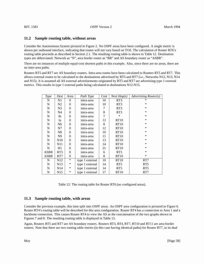
RFC 1583 OSPF Version 2 March 1994
11.2 Sample routing table, without areas
Consider the Autonomous System pictured in Figure 2. No OSPF areas have been configured. A single metric isshown per outbound interface, indicating that routes will not vary based on TOS. The calculation of Router RT6’srouting table proceeds as described in Section 2.1. The resulting routing table is shown in Table 12. Destinationtypes are abbreviated: Network as “N”, area border router as “BR” and AS boundary router as “ASBR”.
There are no instances of multiple equal-cost shortest paths in this example. Also, since there are no areas, there areno inter-area paths.
Routers RT5 and RT7 are AS boundary routers. Intra-area routes have been calculated to Routers RT5 and RT7. Thisallows external routes to be calculated to the destinations advertised by RT5 and RT7 (i.e., Networks N12, N13, N14and N15). It is assumed all AS external advertisements originated by RT5 and RT7 are advertising type 1 externalmetrics. This results in type 1 external paths being calculated to destinations N12-N15.
Type Dest Area Path Type Cost Next Hop(s) Advertising Router(s)N N1 0 intra-area 10 RT3 *N N2 0 intra-area 10 RT3 *N N3 0 intra-area 7 RT3 *N N4 0 intra-area 8 RT3 *N Ib 0 intra-area 7 * *N Ia 0 intra-area 12 RT10 *N N6 0 intra-area 8 RT10 *N N7 0 intra-area 12 RT10 *N N8 0 intra-area 10 RT10 *N N9 0 intra-area 11 RT10 *N N10 0 intra-area 13 RT10 *N N11 0 intra-area 14 RT10 *N H1 0 intra-area 21 RT10 *
ASBR RT5 0 intra-area 6 RT5 *ASBR RT7 0 intra-area 8 RT10 *
N N12 * type 1 external 10 RT10 RT7N N13 * type 1 external 14 RT5 RT5N N14 * type 1 external 14 RT5 RT5N N15 * type 1 external 17 RT10 RT7
Table 12: The routing table for Router RT6 (no configured areas).
11.3 Sample routing table, with areas
Consider the previous example, this time split into OSPF areas. An OSPF area configuration is pictured in Figure 6.Router RT4’s routing table will be described for this area configuration. Router RT4 has a connection to Area 1 and abackbone connection. This causes Router RT4 to view the AS as the concatenation of the two graphs shown inFigures 7 and 8. The resulting routing table is displayed in Table 13.
Again, Routers RT5 and RT7 are AS boundary routers. Routers RT3, RT4, RT7, RT10 and RT11 are area borderrouters. Note that there are two routing table entries (in this case having identical paths) for Router RT7, in its dual
Moy [Page 58]
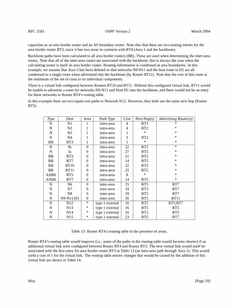
RFC 1583 OSPF Version 2 March 1994
capacities as an area border router and an AS boundary router. Note also that there are two routing entries for thearea border router RT3, since it has two areas in common with RT4 (Area 1 and the backbone).
Backbone paths have been calculated to all area border routers (BR). These are used when determining the inter-arearoutes. Note that all of the inter-area routes are associated with the backbone; this is always the case when thecalculating router is itself an area border router. Routing information is condensed at area boundaries. In thisexample, we assume that Area 3 has been defined so that networks N9-N11 and the host route to H1 are allcondensed to a single route when advertised into the backbone (by Router RT11). Note that the cost of this route isthe minimum of the set of costs to its individual components.
There is a virtual link configured between Routers RT10 and RT11. Without this configured virtual link, RT11 wouldbe unable to advertise a route for networks N9-N11 and Host H1 into the backbone, and there would not be an entryfor these networks in Router RT4’s routing table.
In this example there are two equal-cost paths to Network N12. However, they both use the same next hop (RouterRT5).
Type Dest Area Path Type Cost Next Hop(s) Advertising Router(s)N N1 1 intra-area 4 RT1 *N N2 1 intra-area 4 RT2 *N N3 1 intra-area 1 * *N N4 1 intra-area 3 RT3 *
BR RT3 1 intra-area 1 * *N Ib 0 intra-area 22 RT5 *N Ia 0 intra-area 27 RT5 *
BR RT3 0 intra-area 21 RT5 *BR RT7 0 intra-area 14 RT5 *BR RT10 0 intra-area 22 RT5 *BR RT11 0 intra-area 25 RT5 *
ASBR RT5 0 intra-area 8 * *ASBR RT7 0 intra-area 14 RT5 *
N N6 0 inter-area 15 RT5 RT7N N7 0 inter-area 19 RT5 RT7N N8 0 inter-area 18 RT5 RT7N N9-N11,H1 0 inter-area 26 RT5 RT11N N12 * type 1 external 16 RT5 RT5,RT7N N13 * type 1 external 16 RT5 RT5N N14 * type 1 external 16 RT5 RT5N N15 * type 1 external 23 RT5 RT7
Table 13: Router RT4’s routing table in the presence of areas.
Router RT4’s routing table would improve (i.e., some of the paths in the routing table would become shorter) if anadditional virtual link were configured between Router RT4 and Router RT3. The new virtual link would itself beassociated with the first entry for area border router RT3 in Table 13 (an intra-area path through Area 1). This wouldyield a cost of 1 for the virtual link. The routing table entries changes that would be caused by the addition of thisvirtual link are shown in Table 14.
Moy [Page 59]
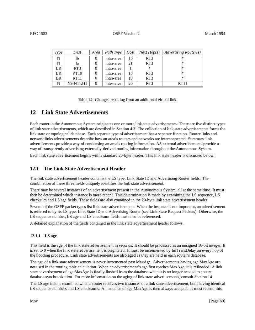
RFC 1583 OSPF Version 2 March 1994
Type Dest Area Path Type Cost Next Hop(s) Advertising Router(s)
N Ib 0 intra-area 16 RT3 *N Ia 0 intra-area 21 RT3 *
BR RT3 0 intra-area 1 * *BR RT10 0 intra-area 16 RT3 *BR RT11 0 intra-area 19 RT3 *N N9-N11,H1 0 inter-area 20 RT3 RT11
Table 14: Changes resulting from an additional virtual link.
12 Link State Advertisements
Each router in the Autonomous System originates one or more link state advertisements. There are five distinct typesof link state advertisements, which are described in Section 4.3. The collection of link state advertisements forms thelink state or topological database. Each separate type of advertisement has a separate function. Router links andnetwork links advertisements describe how an area’s routers and networks are interconnected. Summary linkadvertisements provide a way of condensing an area’s routing information. AS external advertisements provide away of transparently advertising externally-derived routing information throughout the Autonomous System.
Each link state advertisement begins with a standard 20-byte header. This link state header is discussed below.
12.1 The Link State Advertisement Header
The link state advertisement header contains the LS type, Link State ID and Advertising Router fields. Thecombination of these three fields uniquely identifies the link state advertisement.
There may be several instances of an advertisement present in the Autonomous System, all at the same time. It mustthen be determined which instance is more recent. This determination is made by examining the LS sequence, LSchecksum and LS age fields. These fields are also contained in the 20-byte link state advertisement header.
Several of the OSPF packet types list link state advertisements. When the instance is not important, an advertisementis referred to by its LS type, Link State ID and Advertising Router (see Link State Request Packets). Otherwise, theLS sequence number, LS age and LS checksum fields must also be referenced.
A detailed explanation of the fields contained in the link state advertisement header follows.
12.1.1 LS age
This field is the age of the link state advertisement in seconds. It should be processed as an unsigned 16-bit integer. Itis set to 0 when the link state advertisement is originated. It must be incremented by InfTransDelay on every hop ofthe flooding procedure. Link state advertisements are also aged as they are held in each router’s database.
The age of a link state advertisement is never incremented past MaxAge. Advertisements having age MaxAge arenot used in the routing table calculation. When an advertisement’s age first reaches MaxAge, it is reflooded. A linkstate advertisement of age MaxAge is finally flushed from the database when it is no longer needed to ensuredatabase synchronization. For more information on the aging of link state advertisements, consult Section 14.
The LS age field is examined when a router receives two instances of a link state advertisement, both having identicalLS sequence numbers and LS checksums. An instance of age MaxAge is then always accepted as most recent; this
Moy [Page 60]
RFC 1583 OSPF Version 2 March 1994
allows old advertisements to be flushed quickly from the routing domain. Otherwise, if the ages differ by more thanMaxAgeDiff, the instance having the smaller age is accepted as most recent.11 See Section 13.1 for more details.
12.1.2 Options
The Options field in the link state advertisement header indicates which optional capabilities are associated with theadvertisement. OSPF’s optional capabilities are described in Section 4.5. There are currently two optionalcapabilities defined; they are represented by theT-bit andE-bit found in the Options field. The rest of the Optionsfield should be set to zero.
TheE-bit represents OSPF’s ExternalRoutingCapability. This bit should be set in all advertisements associated withthe backbone, and all advertisements associated with non-stub areas (see Section 3.6). It should also be set in all ASexternal link advertisements. It should be reset in all router links, network links and summary link advertisementsassociated with a stub area. For all link state advertisements, the setting of theE-bit is for informational purposesonly; it does not affect the routing table calculation.
TheT-bit represents OSPF’s TOS routing capability. This bit should be set in a router links advertisement if and onlyif the router is capable of calculating separate routes for each IP TOS (see Section 2.4). TheT-bit should always beset in network links advertisements. It should be set in summary link and AS external link advertisements if and onlyif the advertisement describes paths for all TOS values, instead of just the TOS 0 path. Note that, with theT-bit set,there may still be only a single metric in the advertisement (the TOS 0 metric). This would mean that paths fornon-zero TOS exist, but are equivalent to the TOS 0 path. A link state advertisement’sT-bit is examined whencalculating the routing table’s non-zero TOS paths (see Section 16.9).
12.1.3 LS type
The LS type field dictates the format and function of the link state advertisement. Advertisements of different typeshave different names (e.g., router links or network links). All advertisement types, except the AS external linkadvertisements (LS type= 5), are flooded throughout a single area only. AS external link advertisements are floodedthroughout the entire Autonomous System, excepting stub areas (see Section 3.6). Each separate advertisement typeis briefly described below in Table 15.
12.1.4 Link State ID
This field identifies the piece of the routing domain that is being described by the advertisement. Depending on theadvertisement’s LS type, the Link State ID takes on the values listed in Table 16.
Actually, for Type 3 summary link (LS type= 3) advertisements and AS external link (LS type= 5) advertisements,the Link State ID may additionally have one or more of the destination network’s “host” bits set. For example, whenoriginating an AS external link for the network10.0.0.0 with mask of255.0.0.0 , the Link State ID can be setto anything in the range10.0.0.0 through10.255.255.255 inclusive (although10.0.0.0 should be usedwhenever possible). The freedom to set certain host bits allows a router to originate separate advertisements for twonetworks having the same address but different masks. See Appendix F for details.
When the link state advertisement is describing a network (LS type= 2, 3 or 5), the network’s IP address is easilyderived by masking the Link State ID with the network/subnet mask contained in the body of the link state
11MaxAgeDiff is an architectural constant. It indicates the maximum dispersion of ages, in seconds, that can occur for a single link state instanceas it is flooded throughout the routing domain. If two advertisements differ by more than this, they are assumed to be different instances of thesame advertisement. This can occur when a router restarts and loses track of the advertisement’s previous LS sequence number. See Section 13.4for more details.
Moy [Page 61]
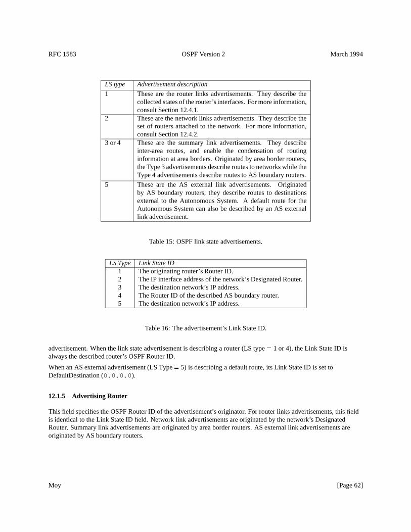
RFC 1583 OSPF Version 2 March 1994
LS type Advertisement description
1 These are the router links advertisements. They describe thecollected states of the router’s interfaces. For more information,consult Section 12.4.1.
2 These are the network links advertisements. They describe theset of routers attached to the network. For more information,consult Section 12.4.2.
3 or 4 These are the summary link advertisements. They describeinter-area routes, and enable the condensation of routinginformation at area borders. Originated by area border routers,the Type 3 advertisements describe routes to networks while theType 4 advertisements describe routes to AS boundary routers.
5 These are the AS external link advertisements. Originatedby AS boundary routers, they describe routes to destinationsexternal to the Autonomous System. A default route for theAutonomous System can also be described by an AS externallink advertisement.
Table 15: OSPF link state advertisements.
LS Type Link State ID1 The originating router’s Router ID.2 The IP interface address of the network’s Designated Router.3 The destination network’s IP address.4 The Router ID of the described AS boundary router.5 The destination network’s IP address.
Table 16: The advertisement’s Link State ID.
advertisement. When the link state advertisement is describing a router (LS type= 1 or 4), the Link State ID isalways the described router’s OSPF Router ID.
When an AS external advertisement (LS Type= 5) is describing a default route, its Link State ID is set toDefaultDestination (0.0.0.0 ).
12.1.5 Advertising Router
This field specifies the OSPF Router ID of the advertisement’s originator. For router links advertisements, this fieldis identical to the Link State ID field. Network link advertisements are originated by the network’s DesignatedRouter. Summary link advertisements are originated by area border routers. AS external link advertisements areoriginated by AS boundary routers.
Moy [Page 62]
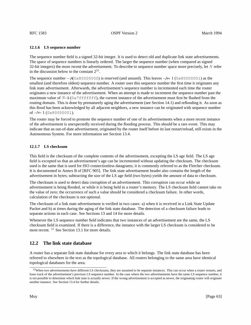
RFC 1583 OSPF Version 2 March 1994
12.1.6 LS sequence number
The sequence number field is a signed 32-bit integer. It is used to detect old and duplicate link state advertisements.The space of sequence numbers is linearly ordered. The larger the sequence number (when compared as signed32-bit integers) the more recent the advertisement. To describe to sequence number space more precisely, letN referin the discussion below to the constant 231.
The sequence number�N(0x80000000 ) is reserved (and unused). This leaves�N+ 1 (0x80000001 ) as thesmallest (and therefore oldest) sequence number. A router uses this sequence number the first time it originates anylink state advertisement. Afterwards, the advertisement’s sequence number is incremented each time the routeroriginates a new instance of the advertisement. When an attempt is made to increment the sequence number past themaximum value ofN�1 (0x7fffffff ), the current instance of the advertisement must first be flushed from therouting domain. This is done by prematurely aging the advertisement (see Section 14.1) and reflooding it. As soon asthis flood has been acknowledged by all adjacent neighbors, a new instance can be originated with sequence numberof �N+ 1 (0x80000001 ).
The router may be forced to promote the sequence number of one of its advertisements when a more recent instanceof the advertisement is unexpectedly received during the flooding process. This should be a rare event. This mayindicate that an out-of-date advertisement, originated by the router itself before its last restart/reload, still exists in theAutonomous System. For more information see Section 13.4.
12.1.7 LS checksum
This field is the checksum of the complete contents of the advertisement, excepting the LS age field. The LS agefield is excepted so that an advertisement’s age can be incremented without updating the checksum. The checksumused is the same that is used for ISO connectionless datagrams; it is commonly referred to as the Fletcher checksum.It is documented in Annex B of [RFC 905]. The link state advertisement header also contains the length of theadvertisement in bytes; subtracting the size of the LS age field (two bytes) yields the amount of data to checksum.
The checksum is used to detect data corruption of an advertisement. This corruption can occur while anadvertisement is being flooded, or while it is being held in a router’s memory. The LS checksum field cannot take onthe value of zero; the occurrence of such a value should be considered a checksum failure. In other words,calculation of the checksum is not optional.
The checksum of a link state advertisement is verified in two cases: a) when it is received in a Link State UpdatePacket and b) at times during the aging of the link state database. The detection of a checksum failure leads toseparate actions in each case. See Sections 13 and 14 for more details.
Whenever the LS sequence number field indicates that two instances of an advertisement are the same, the LSchecksum field is examined. If there is a difference, the instance with the larger LS checksum is considered to bemost recent.12 See Section 13.1 for more details.
12.2 The link state database
A router has a separate link state database for every area to which it belongs. The link state database has beenreferred to elsewhere in the text as the topological database. All routers belonging to the same area have identicaltopological databases for the area.
12When two advertisements have different LS checksums, they are assumed to be separate instances. This can occur when a router restarts, andloses track of the advertisement’s previous LS sequence number. In the case where the two advertisements have the same LS sequence number, itis not possible to determine which link state is actually newer. If the wrong advertisement is accepted as newer, the originating router will originateanother instance. See Section 13.4 for further details.
Moy [Page 63]
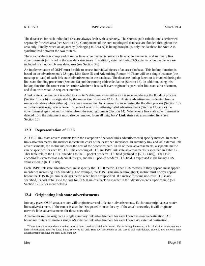
RFC 1583 OSPF Version 2 March 1994
The databases for each individual area are always dealt with separately. The shortest path calculation is performedseparately for each area (see Section 16). Components of the area topological database are flooded throughout thearea only. Finally, when an adjacency (belonging to Area A) is being brought up, only the database for Area A issynchronized between the two routers.
The area database is composed of router links advertisements, network links advertisements, and summary linkadvertisements (all listed in the area data structure). In addition, external routes (AS external advertisements) areincluded in all non-stub area databases (see Section 3.6).
An implementation of OSPF must be able to access individual pieces of an area database. This lookup function isbased on an advertisement’s LS type, Link State ID and Advertising Router.13 There will be a single instance (themost up-to-date) of each link state advertisement in the database. The database lookup function is invoked during thelink state flooding procedure (Section 13) and the routing table calculation (Section 16). In addition, using thislookup function the router can determine whether it has itself ever originated a particular link state advertisement,and if so, with what LS sequence number.
A link state advertisement is added to a router’s database when either a) it is received during the flooding process(Section 13) or b) it is originated by the router itself (Section 12.4). A link state advertisement is deleted from arouter’s database when either a) it has been overwritten by a newer instance during the flooding process (Section 13)or b) the router originates a newer instance of one of its self-originated advertisements (Section 12.4) or c) theadvertisement ages out and is flushed from the routing domain (Section 14). Whenever a link state advertisement isdeleted from the database it must also be removed from all neighbors’Link state retransmission lists(seeSection 10).
12.3 Representation of TOS
All OSPF link state advertisements (with the exception of network links advertisements) specify metrics. In routerlinks advertisements, the metrics indicate the costs of the described interfaces. In summary link and AS external linkadvertisements, the metric indicates the cost of the described path. In all of these advertisements, a separate metriccan be specified for each IP TOS. The encoding of TOS in OSPF link state advertisements is specified in Table 17.That table relates the OSPF encoding to the IP packet header’s TOS field (defined in [RFC 1349]). The OSPFencoding is expressed as a decimal integer, and the IP packet header’s TOS field is expressed in the binary TOSvalues used in [RFC 1349].
Each OSPF link state advertisement must specify the TOS 0 metric. Other TOS metrics, if they appear, must appearin order of increasing TOS encoding. For example, the TOS 8 (maximize throughput) metric must always appearbefore the TOS 16 (minimize delay) metric when both are specified. If a metric for some non-zero TOS is notspecified, its cost defaults to the cost for TOS 0, unless theT-bit is reset in the advertisement’s Options field (seeSection 12.1.2 for more details).
12.4 Originating link state advertisements
Into any given OSPF area, a router will originate several link state advertisements. Each router originates a routerlinks advertisement. If the router is also the Designated Router for any of the area’s networks, it will originatenetwork links advertisements for those networks.
Area border routers originate a single summary link advertisement for each known inter-area destination. ASboundary routers originate a single AS external link advertisement for each known AS external destination.
13There is one instance where a lookup must be done based on partial information. This is during the routing table calculation, when a networklinks advertisement must be found based solely on its Link State ID. The lookup in this case is still well defined, since no two network linksadvertisements can have the same Link State ID.
Moy [Page 64]
RFC 1583 OSPF Version 2 March 1994
OSPF encoding RFC 1349 TOS values0 0000 normal service2 0001 minimize monetary cost4 0010 maximize reliability6 00118 0100 maximize throughput10 010112 011014 011116 1000 minimize delay18 100120 101022 101124 110026 110128 111030 1111
Table 17: Representing TOS in OSPF.
Destinations are advertised one at a time so that the change in any single route can be flooded without reflooding theentire collection of routes. During the flooding procedure, many link state advertisements can be carried by a singleLink State Update packet.
As an example, consider Router RT4 in Figure 6. It is an area border router, having a connection to Area 1 and thebackbone. Router RT4 originates 5 distinct link state advertisements into the backbone (one router links, and onesummary link for each of the networks N1-N4). Router RT4 will also originate 8 distinct link state advertisementsinto Area 1 (one router links and seven summary link advertisements as pictured in Figure 7). If RT4 has beenselected as Designated Router for Network N3, it will also originate a network links advertisement for N3 into Area 1.
In this same figure, Router RT5 will be originating 3 distinct AS external link advertisements (one for each of thenetworks N12-N14). These will be flooded throughout the entire AS, assuming that none of the areas have beenconfigured as stubs. However, if area 3 has been configured as a stub area, the external advertisements for networksN12-N14 will not be flooded into area 3 (see Section 3.6). Instead, Router RT11 would originate a default summarylink advertisement that would be flooded throughout area 3 (see Section 12.4.3). This instructs all of area 3’s internalrouters to send their AS external traffic to RT11.
Whenever a new instance of a link state advertisement is originated, its LS sequence number is incremented, its LSage is set to 0, its LS checksum is calculated, and the advertisement is added to the link state database and floodedout the appropriate interfaces. See Section 13.2 for details concerning the installation of the advertisement into thelink state database. See Section 13.3 for details concerning the flooding of newly originated advertisements.
The ten events that can cause a new instance of a link state advertisement to be originated are:
1. The LS age field of one of the router’s self-originated advertisements reaches the value LSRefreshTime.In thiscase, a new instance of the link state advertisement is originated, even though the contents of the advertisement(apart from the link state advertisement header) will be the same. This guarantees periodic originations of alllink state advertisements. This periodic updating of link state advertisements adds robustness to the link statealgorithm. Link state advertisements that solely describe unreachable destinations should not be refreshed, butshould instead be flushed from the routing domain (see Section 14.1).
Moy [Page 65]
RFC 1583 OSPF Version 2 March 1994
When whatever is being described by a link state advertisement changes, a new advertisement is originated.However, two instances of the same link state advertisement may not be originated within the time periodMinLSInterval. This may require that the generation of the next instance be delayed by up to MinLSInterval. Thefollowing events may cause the contents of a link state advertisement to change. These events should cause neworiginations if and only if the contents of the new advertisement would be different:
2. An interface’s state changes(see Section 9.1). This may mean that it is necessary to produce a new instance ofthe router links advertisement.
3. An attached network’s Designated Router changes.A new router links advertisement should be originated.Also, if the router itself is now the Designated Router, a new network links advertisement should be produced.If the router itself is no longer the Designated Router, any network links advertisement that it might haveoriginated for the network should be flushed from the routing domain (see Section 14.1).
4. One of the neighboring routers changes to/from the FULL state.This may mean that it is necessary to producea new instance of the router links advertisement. Also, if the router is itself the Designated Router for theattached network, a new network links advertisement should be produced.
The next four events concern area border routers only:
5. An intra-area route has been added/deleted/modifiedin the routing table. This may cause a new instance of asummary links advertisement (for this route) to be originated in each attached area (possibly including thebackbone).
6. An inter-area route has been added/deleted/modifiedin the routing table. This may cause a new instance of asummary links advertisement (for this route) to be originated in each attached area (but NEVER for thebackbone).
7. The router becomes newly attached to an area.The router must then originate summary link advertisementsinto the newly attached area for all pertinent intra-area and inter-area routes in the router’s routing table. SeeSection 12.4.3 for more details.
8. When the state of one of the router’s configured virtual links changes,it may be necessary to originate a newrouter links advertisement into the virtual link’s transit area (see the discussion of the router linksadvertisement’s bit V in Section 12.4.1), as well as originating a new router links advertisement into thebackbone.
The last two events concern AS boundary routers (and former AS boundary routers) only:
9. An external route gained through direct experiencewith an external routing protocol (like EGP) changes. Thiswill cause an AS boundary router to originate a new instance of an AS external link advertisement.
10. A router ceases to be an AS boundary router, perhaps after restarting. In this situation the router should flushall AS external link advertisements that it had previously originated. These advertisements can be flushed viathe premature aging procedure specified in Section 14.1.
The construction of each type of link state advertisement is explained in detail below. In general, these sectionsdescribe the contents of the advertisement body (i.e., the part coming after the 20-byte advertisement header). Forinformation concerning the building of the link state advertisement header, see Section 12.1.
Moy [Page 66]
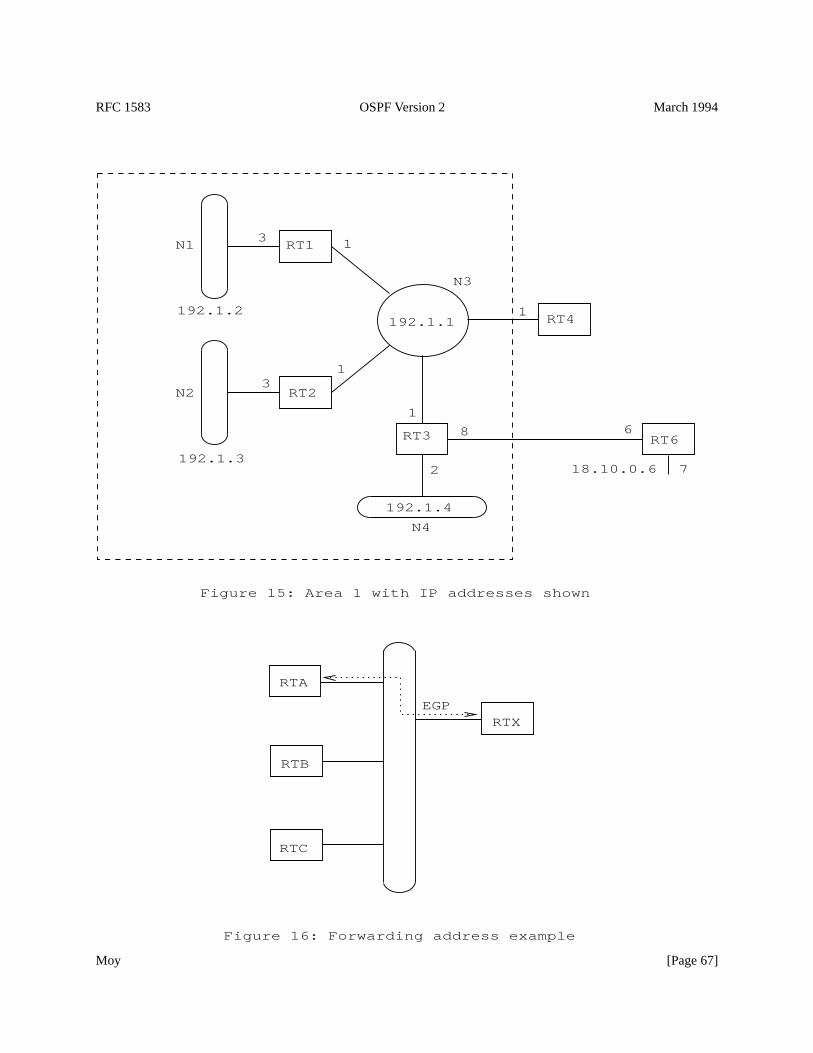
RFC 1583 OSPF Version 2 March 1994
Figure 16: Forwarding address example
EGPRTX
RTC
RTB
RTA
1
192.1.1
192.1.4
192.1.2
192.1.3
RT3
RT4
RT1
RT2
RT6
N3
N4
N1
N2
18.10.0.6
1
1
3
3
1
2
8
7
6
Figure 15: Area 1 with IP addresses shown
Moy [Page 67]
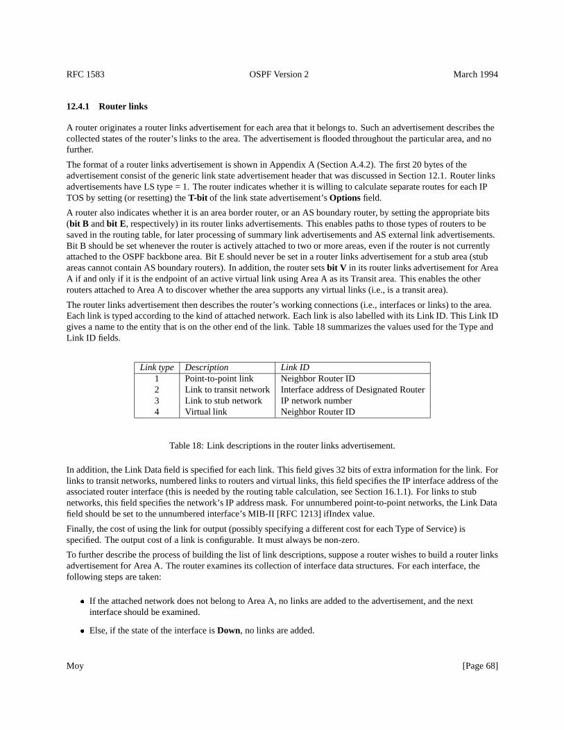
RFC 1583 OSPF Version 2 March 1994
12.4.1 Router links
A router originates a router links advertisement for each area that it belongs to. Such an advertisement describes thecollected states of the router’s links to the area. The advertisement is flooded throughout the particular area, and nofurther.
The format of a router links advertisement is shown in Appendix A (Section A.4.2). The first 20 bytes of theadvertisement consist of the generic link state advertisement header that was discussed in Section 12.1. Router linksadvertisements have LS type = 1. The router indicates whether it is willing to calculate separate routes for each IPTOS by setting (or resetting) theT-bit of the link state advertisement’sOptions field.
A router also indicates whether it is an area border router, or an AS boundary router, by setting the appropriate bits(bit B andbit E , respectively) in its router links advertisements. This enables paths to those types of routers to besaved in the routing table, for later processing of summary link advertisements and AS external link advertisements.Bit B should be set whenever the router is actively attached to two or more areas, even if the router is not currentlyattached to the OSPF backbone area. Bit E should never be set in a router links advertisement for a stub area (stubareas cannot contain AS boundary routers). In addition, the router setsbit V in its router links advertisement for AreaA if and only if it is the endpoint of an active virtual link using Area A as its Transit area. This enables the otherrouters attached to Area A to discover whether the area supports any virtual links (i.e., is a transit area).
The router links advertisement then describes the router’s working connections (i.e., interfaces or links) to the area.Each link is typed according to the kind of attached network. Each link is also labelled with its Link ID. This Link IDgives a name to the entity that is on the other end of the link. Table 18 summarizes the values used for the Type andLink ID fields.
Link type Description Link ID1 Point-to-point link Neighbor Router ID2 Link to transit network Interface address of Designated Router3 Link to stub network IP network number4 Virtual link Neighbor Router ID
Table 18: Link descriptions in the router links advertisement.
In addition, the Link Data field is specified for each link. This field gives 32 bits of extra information for the link. Forlinks to transit networks, numbered links to routers and virtual links, this field specifies the IP interface address of theassociated router interface (this is needed by the routing table calculation, see Section 16.1.1). For links to stubnetworks, this field specifies the network’s IP address mask. For unnumbered point-to-point networks, the Link Datafield should be set to the unnumbered interface’s MIB-II [RFC 1213] ifIndex value.
Finally, the cost of using the link for output (possibly specifying a different cost for each Type of Service) isspecified. The output cost of a link is configurable. It must always be non-zero.
To further describe the process of building the list of link descriptions, suppose a router wishes to build a router linksadvertisement for Area A. The router examines its collection of interface data structures. For each interface, thefollowing steps are taken:
� If the attached network does not belong to Area A, no links are added to the advertisement, and the nextinterface should be examined.
� Else, if the state of the interface isDown, no links are added.
Moy [Page 68]
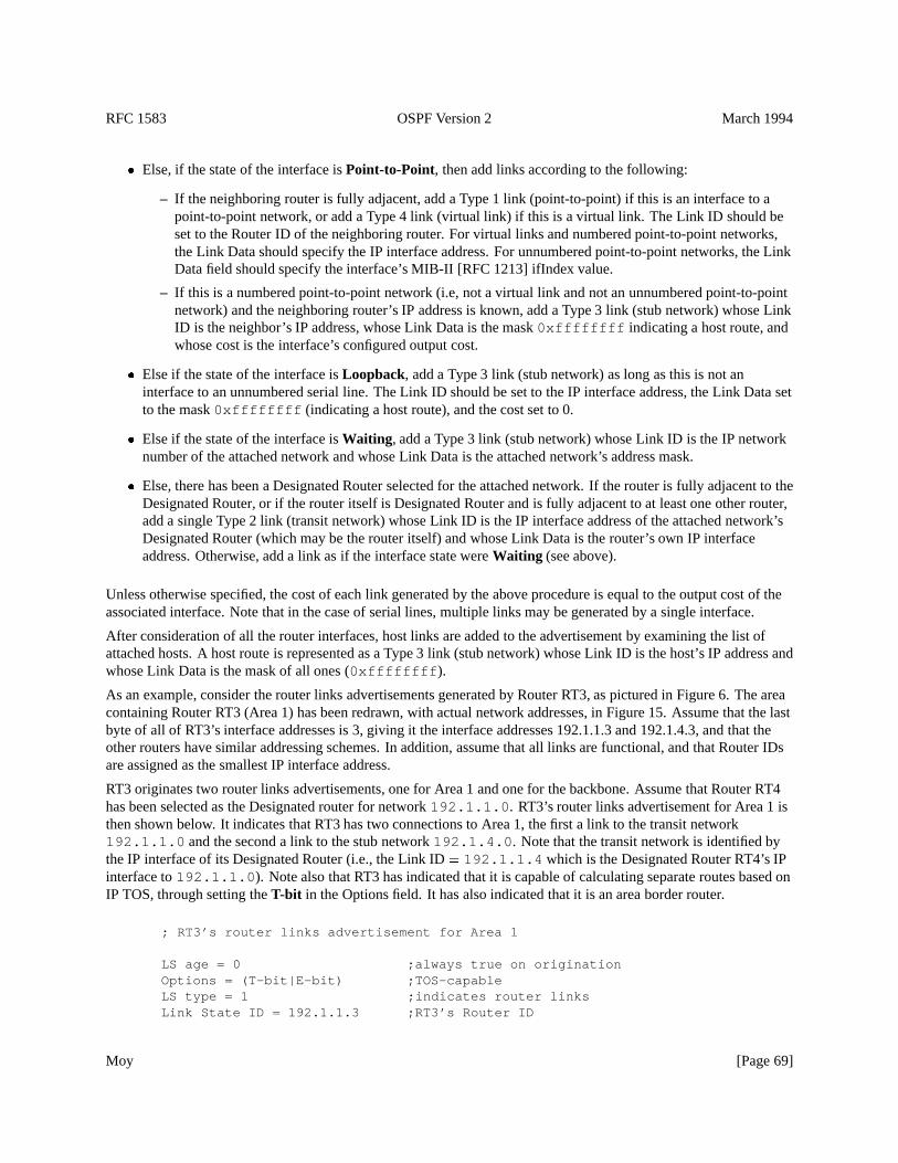
RFC 1583 OSPF Version 2 March 1994
� Else, if the state of the interface isPoint-to-Point, then add links according to the following:
– If the neighboring router is fully adjacent, add a Type 1 link (point-to-point) if this is an interface to apoint-to-point network, or add a Type 4 link (virtual link) if this is a virtual link. The Link ID should beset to the Router ID of the neighboring router. For virtual links and numbered point-to-point networks,the Link Data should specify the IP interface address. For unnumbered point-to-point networks, the LinkData field should specify the interface’s MIB-II [RFC 1213] ifIndex value.
– If this is a numbered point-to-point network (i.e, not a virtual link and not an unnumbered point-to-pointnetwork) and the neighboring router’s IP address is known, add a Type 3 link (stub network) whose LinkID is the neighbor’s IP address, whose Link Data is the mask0xffffffff indicating a host route, andwhose cost is the interface’s configured output cost.
� Else if the state of the interface isLoopback, add a Type 3 link (stub network) as long as this is not aninterface to an unnumbered serial line. The Link ID should be set to the IP interface address, the Link Data setto the mask0xffffffff (indicating a host route), and the cost set to 0.
� Else if the state of the interface isWaiting , add a Type 3 link (stub network) whose Link ID is the IP networknumber of the attached network and whose Link Data is the attached network’s address mask.
� Else, there has been a Designated Router selected for the attached network. If the router is fully adjacent to theDesignated Router, or if the router itself is Designated Router and is fully adjacent to at least one other router,add a single Type 2 link (transit network) whose Link ID is the IP interface address of the attached network’sDesignated Router (which may be the router itself) and whose Link Data is the router’s own IP interfaceaddress. Otherwise, add a link as if the interface state wereWaiting (see above).
Unless otherwise specified, the cost of each link generated by the above procedure is equal to the output cost of theassociated interface. Note that in the case of serial lines, multiple links may be generated by a single interface.
After consideration of all the router interfaces, host links are added to the advertisement by examining the list ofattached hosts. A host route is represented as a Type 3 link (stub network) whose Link ID is the host’s IP address andwhose Link Data is the mask of all ones (0xffffffff ).
As an example, consider the router links advertisements generated by Router RT3, as pictured in Figure 6. The areacontaining Router RT3 (Area 1) has been redrawn, with actual network addresses, in Figure 15. Assume that the lastbyte of all of RT3’s interface addresses is 3, giving it the interface addresses 192.1.1.3 and 192.1.4.3, and that theother routers have similar addressing schemes. In addition, assume that all links are functional, and that Router IDsare assigned as the smallest IP interface address.
RT3 originates two router links advertisements, one for Area 1 and one for the backbone. Assume that Router RT4has been selected as the Designated router for network192.1.1.0 . RT3’s router links advertisement for Area 1 isthen shown below. It indicates that RT3 has two connections to Area 1, the first a link to the transit network192.1.1.0 and the second a link to the stub network192.1.4.0 . Note that the transit network is identified bythe IP interface of its Designated Router (i.e., the Link ID= 192.1.1.4 which is the Designated Router RT4’s IPinterface to192.1.1.0 ). Note also that RT3 has indicated that it is capable of calculating separate routes based onIP TOS, through setting theT-bit in the Options field. It has also indicated that it is an area border router.
; RT3’s router links advertisement for Area 1
LS age = 0 ;always true on originationOptions = (T-bit|E-bit) ;TOS-capableLS type = 1 ;indicates router linksLink State ID = 192.1.1.3 ;RT3’s Router ID
Moy [Page 69]
RFC 1583 OSPF Version 2 March 1994
Advertising Router = 192.1.1.3 ;RT3’s Router IDbit E = 0 ;not an AS boundary routerbit B = 1 ;RT3 is an area border router#links = 2
Link ID = 192.1.1.4 ;IP address of Designated RouterLink Data = 192.1.1.3 ;RT3’s IP interface to netType = 2 ;connects to transit network# other metrics = 0TOS 0 metric = 1
Link ID = 192.1.4.0 ;IP Network numberLink Data = 0xffffff00 ;Network maskType = 3 ;connects to stub network# other metrics = 0TOS 0 metric = 2
Next RT3’s router links advertisement for the backbone is shown. It indicates that RT3 has a single attachment to thebackbone. This attachment is via an unnumbered point-to-point link to Router RT6. RT3 has again indicated that it isTOS-capable, and that it is an area border router.
; RT3’s router links advertisement for the backbone
LS age = 0 ;always true on originationOptions = (T-bit|E-bit) ;TOS-capableLS type = 1 ;indicates router linksLink State ID = 192.1.1.3 ;RT3’s router IDAdvertising Router = 192.1.1.3 ;RT3’s router IDbit E = 0 ;not an AS boundary routerbit B = 1 ;RT3 is an area border router#links = 1
Link ID = 18.10.0.6 ;Neighbor’s Router IDLink Data = 0.0.0.3 ;MIB-II ifIndex of P-P linkType = 1 ;connects to router# other metrics = 0TOS 0 metric = 8
Even though Router RT3 has indicated that it is TOS-capable in the above examples, only a single metric (the TOS 0metric) has been specified for each interface. Different metrics can be specified for each TOS. The encoding of TOSin OSPF link state advertisements is described in Section 12.3.
As an example, suppose the point-to-point link between Routers RT3 and RT6 in Figure 15 is a satellite link. The ASadministrator may want to encourage the use of the line for high bandwidth traffic. This would be done by setting themetric artificially low for the appropriate TOS value. Router RT3 would then originate the following router linksadvertisement for the backbone (TOS 8=maximize throughput):
; RT3’s router links advertisement for the backbone
LS age = 0 ;always true on originationOptions = (T-bit|E-bit) ;TOS-capableLS type = 1 ;indicates router linksLink State ID = 192.1.1.3 ;RT3’s Router IDAdvertising Router = 192.1.1.3
Moy [Page 70]
RFC 1583 OSPF Version 2 March 1994
bit E = 0 ;not an AS boundary routerbit B = 1 ;RT3 is an area border router#links = 1
Link ID = 18.10.0.6 ;Neighbor’s Router IDLink Data = 0.0.0.3 ;MIB-II ifIndex of P-P linkType = 1 ;connects to router# other metrics = 1TOS 0 metric = 8
TOS = 8 ;Maximize throughputmetric = 1 ;traffic preferred
12.4.2 Network links
A network links advertisement is generated for every transit multi-access network. (A transit network is a networkhaving two or more attached routers). The network links advertisement describes all the routers that are attached tothe network.
The Designated Router for the network originates the advertisement. The Designated Router originates theadvertisement only if it is fully adjacent to at least one other router on the network. The network links advertisementis flooded throughout the area that contains the transit network, and no further. The networks links advertisementlists those routers that are fully adjacent to the Designated Router; each fully adjacent router is identified by its OSPFRouter ID. The Designated Router includes itself in this list.
The Link State ID for a network links advertisement is the IP interface address of the Designated Router. This value,masked by the network’s address mask (which is also contained in the network links advertisement) yields thenetwork’s IP address.
A router that has formerly been the Designated Router for a network, but is no longer, should flush the network linksadvertisement that it had previously originated. This advertisement is no longer used in the routing table calculation.It is flushed by prematurely incrementing the advertisement’s age to MaxAge and reflooding (see Section 14.1). Inaddition, in those rare cases where a router’s Router ID has changed, any network links advertisements that wereoriginated with the router’s previous Router ID must be flushed. Since the router may have no idea what it’s previousRouter ID might have been, these network links advertisements are indicated by having their Link State ID equal toone of the router’s IP interface addresses and their Advertising Router not equal to the router’s current Router ID (seeSection 13.4 for more details).
As an example of a network links advertisement, again consider the area configuration in Figure 6. Network linksadvertisements are originated for Network N3 in Area 1, Networks N6 and N8 in Area 2, and Network N9 in Area 3.Assuming that Router RT4 has been selected as the Designated Router for Network N3, the following network linksadvertisement is generated by RT4 on behalf of Network N3 (see Figure 15 for the address assignments):
; network links advertisement for Network N3
LS age = 0 ;always true on originationOptions = (T-bit|E-bit) ;TOS-capableLS type = 2 ;indicates network linksLink State ID = 192.1.1.4 ;IP address of Designated RouterAdvertising Router = 192.1.1.4 ;RT4’s Router IDNetwork Mask = 0xffffff00
Attached Router = 192.1.1.4 ;Router IDAttached Router = 192.1.1.1 ;Router IDAttached Router = 192.1.1.2 ;Router IDAttached Router = 192.1.1.3 ;Router ID
Moy [Page 71]
RFC 1583 OSPF Version 2 March 1994
12.4.3 Summary links
Each summary link advertisement describes a route to a single destination. Summary link advertisements are floodedthroughout a single area only. The destination described is one that is external to the area, yet still belonging to theAutonomous System.
Summary link advertisements are originated by area border routers. The precise summary routes to advertise into anarea are determined by examining the routing table structure (see Section 11) in accordance with the algorithmdescribed below. Note that only intra-area routes are advertised into the backbone, while both intra-area andinter-area routes are advertised into the other areas.
To determine which routes to advertise into an attached Area A, each routing table entry is processed as follows.Remember that each routing table entry describes a set of equal-cost best paths to a particular destination:
� Only Destination Types of network and AS boundary router are advertised in summary link advertisements. Ifthe routing table entry’sDestination Type is area border router, examine the next routing table entry.
� AS external routes are never advertised in summary link advertisements. If the routing table entry hasPath-typeof type 1 external or type 2 external, examine the next routing table entry.
� Else, if the area associated with this set of paths is the Area A itself, do not generate a summary linkadvertisement for the route.14
� Else, if the next hops associated with this set of paths belong to Area A itself, do not generate a summary linkadvertisement for the route.15 This is the logical equivalent of a Distance Vector protocol’s split horizon logic.
� Else, if the routing table cost equals or exceeds the value LSInfinity, a summary link advertisement cannot begenerated for this route.
� Else, if the destination of this route is an AS boundary router, generate a Type 4 link state advertisement for thedestination, withLink State ID equal to the AS boundary router’s Router ID and metric equal to the routingtable entry’s cost. These advertisements should not be generated if Area A has been configured as a stub area.
� Else, the Destination type is network. If this is an inter-area route, generate a Type 3 advertisement for thedestination, withLink State ID equal to the network’s address (if necessary, the Link State ID can also haveone or more of the network’s “host” bits set; see Appendix F for details) and metric equal to the routing tablecost.
� The one remaining case is an intra-area route to a network. This means that the network is contained in one ofthe router’s directly attached areas. In general, this information must be condensed before appearing insummary link advertisements. Remember that an area has been defined as a list of address ranges, each rangeconsisting of an [address,mask] pair and a status indication of either Advertise or DoNotAdvertise. At most asingle Type 3 advertisement is made for each range. When the range’s status indicates Advertise, a Type 3advertisement is generated with Link State ID equal to the range’s address (if necessary, the Link State ID canalso have one or more of the range’s “host” bits set; see Appendix F for details) and cost equal to the smallestcost of any of the component networks. When the range’s status indicates DoNotAdvertise, the Type 3advertisement is suppressed and the component networks remain hidden from other areas.
14This clause covers the case: Inter-area routes are not summarized to the backbone. This is because inter-area routes are always associated withthe backbone area.
15This clause is only invoked when Area A is a Transit area supporting one or more virtual links. For example, in the area configuration of Figure6, Router RT11 need only originate a single summary link having the (collapsed) destination N9-N11,H1 into its connected Transit area Area 2,since all of its other eligible routes have next hops belonging to Area 2 (and as such only need be advertised by other area border routers; in thiscase, Routers RT10 and RT7).
Moy [Page 72]
RFC 1583 OSPF Version 2 March 1994
By default, if a network is not contained in any explicitly configured address range, a Type 3 advertisement isgenerated with Link State ID equal to the network’s address (if necessary, the Link State ID can also have oneor more of the network’s “host” bits set; see Appendix F for details) and metric equal to the network’s routingtable cost.
If virtual links are being used to provide/increase connectivity of the backbone, routing informationconcerning the backbone networks should not be condensed before being summarized into the virtual links’Transit areas. Nor should the advertisement of backbone networks into Transit areas be suppressed. In otherwords, the backbone’s configured ranges should be ignored when originating summary links into Transit areas.The existence of virtual links is determined during the shortest path calculation for the Transit areas (seeSection 16.1).
If a router advertises a summary advertisement for a destination which then becomes unreachable, the router mustthen flush the advertisement from the routing domain by setting its age to MaxAge and reflooding (see Section 14.1).Also, if the destination is still reachable, yet can no longer be advertised according to the above procedure (e.g., it isnow an inter-area route, when it used to be an intra-area route associated with some non-backbone area; it would thusno longer be advertisable to the backbone), the advertisement should also be flushed from the routing domain.
For an example of summary link advertisements, consider again the area configuration in Figure 6. Routers RT3,RT4, RT7, RT10 and RT11 are all area border routers, and therefore are originating summary link advertisements.Consider in particular Router RT4. Its routing table was calculated as the example in Section 11.3. RT4 originatessummary link advertisements into both the backbone and Area 1. Into the backbone, Router RT4 originates separateadvertisements for each of the networks N1-N4. Into Area 1, Router RT4 originates separate advertisements fornetworks N6-N8 and the AS boundary routers RT5,RT7. It also condenses host routes Ia and Ib into a singlesummary link advertisement. Finally, the routes to networks N9,N10,N11 and Host H1 are advertised by a singlesummary link advertisement. This condensation was originally performed by the Router RT11.
These advertisements are illustrated graphically in Figures 7 and 8. Two of the summary link advertisementsoriginated by Router RT4 follow. The actual IP addresses for the networks and routers in question have beenassigned in Figure 15.
; summary link advertisement for Network N1,; originated by Router RT4 into the backbone
LS age = 0 ;always true on originationOptions = (T-bit|E-bit) ;TOS-capableLS type = 3 ;indicates summary link to IP netLink State ID = 192.1.2.0 ;N1’s IP network numberAdvertising Router = 192.1.1.4 ;RT4’s ID
TOS = 0metric = 4
; summary link advertisement for AS boundary Router RT7; originated by Router RT4 into Area 1
LS age = 0 ;always true on originationOptions = (T-bit|E-bit) ;TOS-capableLS type = 4 ;indicates summary link to ASBRLink State ID = Router RT7’s IDAdvertising Router = 192.1.1.4 ;RT4’s ID
TOS = 0metric = 14
Moy [Page 73]
RFC 1583 OSPF Version 2 March 1994
Summary link advertisements pertain to a single destination (IP network or AS boundary router). However, for asingle destination there may be separate sets of paths, and therefore separate routing table entries, for each Type ofService. All these entries must be considered when building the summary link advertisement for the destination; asingle advertisement must specify the separate costs (if they exist) for each TOS. The encoding of TOS in OSPF linkstate advertisements is described in Section 12.3.
Clearing theT-bit in the Options field of a summary link advertisement indicates that there is a TOS 0 path to thedestination, but no paths for non-zero TOS. This can happen when non-TOS-capable routers exist in the routingdomain (see Section 2.4).
12.4.4 Originating summary links into stub areas
The algorithm in Section 12.4.3 is optional when Area A is an OSPF stub area. Area border routers connecting to astub area can originate summary link advertisements into the area according to the above Section’s algorithm, or canchoose to originate only a subset of the advertisements, possibly under configuration control. The feweradvertisements originated, the smaller the stub area’s link state database, further reducing the demands on its routers’resources. However, omitting advertisements may also lead to sub-optimal inter-area routing, although routing willcontinue to function.
As specified in Section 12.4.3, Type 4 link state advertisements (ASBR summary links) are never originated into stubareas.
In a stub area, instead of importing external routes each area border router originates a “default summary link” intothe area. TheLink State ID for the default summary link is set to DefaultDestination, and the metric set to the(per-area) configurable parameter StubDefaultCost. Note that StubDefaultCost need not be configured identically inall of the stub area’s area border routers.
12.4.5 AS external links
AS external link advertisements describe routes to destinations external to the Autonomous System. Most ASexternal link advertisements describe routes to specific external destinations; in these cases the advertisement’s LinkState ID is set to the destination network’s IP address (if necessary, the Link State ID can also have one or more ofthe network’s “host” bits set; see Appendix F for details). However, a default route for the Autonomous System canbe described in an AS external link advertisement by setting the advertisement’sLink State ID toDefaultDestination (0.0.0.0 ). AS external link advertisements are originated by AS boundary routers. An ASboundary router originates a single AS external link advertisement for each external route that it has learned, eitherthrough another routing protocol (such as EGP), or through configuration information.
In general, AS external link advertisements are the only type of link state advertisements that are flooded throughoutthe entire Autonomous System; all other types of link state advertisements are specific to a single area. However, ASexternal link advertisements are not flooded into/throughout stub areas (see Section 3.6). This enables a reduction inlink state database size for routers internal to stub areas.
The metric that is advertised for an external route can be one of two types. Type 1 metrics are comparable to the linkstate metric. Type 2 metrics are assumed to be larger than the cost of any intra-AS path. As with summary linkadvertisements, if separate paths exist based on TOS, separate TOS costs can be included in the AS external linkadvertisement. The encoding of TOS in OSPF link state advertisements is described in Section 12.3. If theT-bit ofthe advertisement’sOptions field is clear, no non-zero TOS paths to the destination exist.
If a router advertises an AS external link advertisement for a destination which then becomes unreachable, the routermust then flush the advertisement from the routing domain by setting its age to MaxAge and reflooding (seeSection 14.1).
Moy [Page 74]
RFC 1583 OSPF Version 2 March 1994
For an example of AS external link advertisements, consider once again the AS pictured in Figure 6. There are twoAS boundary routers: RT5 and RT7. Router RT5 originates three external link advertisements, for networksN12-N14. Router RT7 originates two external link advertisements, for networks N12 and N15. Assume that RT7 haslearned its route to N12 via EGP, and that it wishes to advertise a Type 2 metric to the AS. RT7 would then originatethe following advertisement for N12:
; AS external link advertisement for Network N12,; originated by Router RT7
LS age = 0 ;always true on originationOptions = (T-bit|E-bit) ;TOS-capableLS type = 5 ;indicates AS external linkLink State ID = N12’s IP network numberAdvertising Router = Router RT7’s ID
bit E = 1 ;Type 2 metricTOS = 0metric = 2Forwarding address = 0.0.0.0
In the above example, theforwarding addressfield has been set to0.0.0.0 , indicating that packets for theexternal destination should be forwarded to the advertising OSPF router (RT7). This is not always desirable.Consider the example pictured in Figure 16. There are three OSPF routers (RTA, RTB and RTC) connected to acommon network. Only one of these routers, RTA, is exchanging EGP information with the non-OSPF router RTX.RTA must then originate AS external link advertisements for those destinations it has learned from RTX. By usingthe AS external link advertisement’sforwarding addressfield, RTA can specify that packets for these destinationsbe forwarded directly to RTX. Without this feature, Routers RTB and RTC would take an extra hop to get to thesedestinations.
Note that when theforwarding addressfield is non-zero, it should point to a router belonging to anotherAutonomous System.
A forwarding addresscan also be specified for the default route. For example, in figure 16 RTA may want tospecify that all externally-destined packets should by default be forwarded to its EGP peer RTX. The resulting ASexternal link advertisement is pictured below. Note that the Link State ID is set to DefaultDestination.
; Default route, originated by Router RTA; Packets forwarded through RTX
LS age = 0 ;always true on originationOptions = (T-bit|E-bit) ;TOS-capableLS type = 5 ;indicates AS external linkLink State ID = DefaultDestination ; default routeAdvertising Router = Router RTA’s ID
bit E = 1 ;Type 2 metricTOS = 0metric = 1Forwarding address = RTX’s IP address
In figure 16, suppose instead that both RTA and RTB exchange EGP information with RTX. In this case, RTA andRTB would originate the same set of AS external link advertisements. These advertisements, if they specify the samemetric, would be functionally equivalent since they would specify the same destination and forwarding address(RTX). This leads to a clear duplication of effort. If only one of RTA or RTB originated the set of external
Moy [Page 75]
RFC 1583 OSPF Version 2 March 1994
advertisements, the routing would remain the same, and the size of the link state database would decrease. However,it must be unambiguously defined as to which router originates the advertisements (otherwise neither may, or theidentity of the originator may oscillate). The following rule is thereby established:if two routers, both reachablefrom one another, originate functionally equivalent AS external advertisements (i.e., same destination, cost andnon-zero forwarding address), then the advertisement originated by the router having the highest OSPF Router ID isused. The router having the lower OSPF Router ID can then flush its advertisement. Flushing a link stateadvertisement is discussed in Section 14.1.
13 The Flooding Procedure
Link State Update packets provide the mechanism for flooding link state advertisements. A Link State Update packetmay contain several distinct advertisements, and floods each advertisement one hop further from its point oforigination. To make the flooding procedure reliable, each advertisement must be acknowledged separately.Acknowledgments are transmitted in Link State Acknowledgment packets. Many separate acknowledgments canalso be grouped together into a single packet.
The flooding procedure starts when a Link State Update packet has been received. Many consistency checks havebeen made on the received packet before being handed to the flooding procedure (see Section 8.2). In particular, theLink State Update packet has been associated with a particular neighbor, and a particular area. If the neighbor is in alesser state thanExchange, the packet should be dropped without further processing.
All types of link state advertisements, other than AS external links, are associated with a specific area. However, linkstate advertisements do not contain an area field. A link state advertisement’s area must be deduced from the LinkState Update packet header.
For each link state advertisement contained in the packet, the following steps are taken:
1. Validate the advertisement’s LS checksum. If the checksum turns out to be invalid, discard the advertisementand get the next one from the Link State Update packet.
2. Examine the link state advertisement’s LS type. If the LS type is unknown, discard the advertisement and getthe next one from the Link State Update Packet. This specification defines LS types 1-5 (see Section 4.3).
3. Else if this is a AS external link advertisement (LS type= 5), and the area has been configured as a stub area,discard the advertisement and get the next one from the Link State Update Packet. AS external linkadvertisements are not flooded into/throughout stub areas (see Section 3.6).
4. Else if the advertisement’s LS age is equal to MaxAge, and there is currently no instance of the advertisementin the router’s link state database, then take the following actions:
(a) Acknowledge the receipt of the advertisement by sending a Link State Acknowledgment packet back tothe sending neighbor (see Section 13.5).
(b) Purge all outstanding requests for equal or previous instances of the advertisement from the sendingneighbor’sLink State Request list(see Section 10).
(c) If the sending neighbor is in stateExchangeor in stateLoading, then install the MaxAge advertisementin the link state database. Otherwise, simply discard the advertisement. In either case, examine the nextadvertisement (if any) listed in the Link State Update packet.
5. Otherwise, find the instance of this advertisement that is currently contained in the router’s link state database.If there is no database copy, or the received advertisement is more recent than the database copy (seeSection 13.1 below for the determination of which advertisement is more recent) the following steps must beperformed:
Moy [Page 76]
RFC 1583 OSPF Version 2 March 1994
(a) If there is already a database copy, and if the database copy was installed less than MinLSIntervalseconds ago, discard the new advertisement (without acknowledging it) and examine the nextadvertisement (if any) listed in the Link State Update packet.
(b) Otherwise immediately flood the new advertisement out some subset of the router’s interfaces (seeSection 13.3). In some cases (e.g., the state of the receiving interface isDR and the advertisement wasreceived from a router other than the Backup DR) the advertisement will be flooded back out thereceiving interface. This occurrence should be noted for later use by the acknowledgment process(Section 13.5).
(c) Remove the current database copy from all neighbors’Link state retransmission lists.
(d) Install the new advertisement in the link state database (replacing the current database copy). This maycause the routing table calculation to be scheduled. In addition, timestamp the new advertisement withthe current time (i.e., the time it was received). The flooding procedure cannot overwrite the newlyinstalled advertisement until MinLSInterval seconds have elapsed. The advertisement installationprocess is discussed further in Section 13.2.
(e) Possibly acknowledge the receipt of the advertisement by sending a Link State Acknowledgment packetback out the receiving interface. This is explained below in Section 13.5.
(f) If this new link state advertisement indicates that it was originated by the receiving router itself (i.e., isconsidered a self-originated advertisement), the router must take special action, either updating theadvertisement or in some cases flushing it from the routing domain. For a description of howself-originated advertisements are detected and subsequently handled, see Section 13.4.
6. Else, if there is an instance of the advertisement on the sending neighbor’sLink state request list, an error hasoccurred in the Database Exchange process. In this case, restart the Database Exchange process by generatingthe neighbor eventBadLSReqfor the sending neighbor and stop processing the Link State Update packet.
7. Else, if the received advertisement is the same instance as the database copy (i.e., neither one is more recent)the following two steps should be performed:
(a) If the advertisement is listed in theLink state retransmission list for the receiving adjacency, the routeritself is expecting an acknowledgment for this advertisement. The router should treat the receivedadvertisement as an acknowledgment, by removing the advertisement from theLink stateretransmission list. This is termed an “implied acknowledgment”. Its occurrence should be noted forlater use by the acknowledgment process (Section 13.5).
(b) Possibly acknowledge the receipt of the advertisement by sending a Link State Acknowledgment packetback out the receiving interface. This is explained below in Section 13.5.
8. Else, the database copy is more recent. Note an unusual event to network management, discard theadvertisement and process the next link state advertisement contained in the Link State Update packet.
13.1 Determining which link state is newer
When a router encounters two instances of a link state advertisement, it must determine which is more recent. Thisoccurred above when comparing a received advertisement to its database copy. This comparison must also be doneduring the Database Exchange procedure which occurs during adjacency bring-up.
A link state advertisement is identified by its LS type, Link State ID and Advertising Router. For two instances of thesame advertisement, the LS sequence number, LS age, and LS checksum fields are used to determine which instanceis more recent:
Moy [Page 77]
RFC 1583 OSPF Version 2 March 1994
� The advertisement having the newer LS sequence number is more recent. See Section 12.1.6 for anexplanation of the LS sequence number space. If both instances have the same LS sequence number, then:
� If the two instances have different LS checksums, then the instance having the larger LS checksum (whenconsidered as a 16-bit unsigned integer) is considered more recent.
� Else, if only one of the instances has its LS age field set to MaxAge, the instance of age MaxAge is consideredto be more recent.
� Else, if the LS age fields of the two instances differ by more than MaxAgeDiff, the instance having the smaller(younger) LS age is considered to be more recent.
� Else, the two instances are considered to be identical.
13.2 Installing link state advertisements in the database
Installing a new link state advertisement in the database, either as the result of flooding or a newly self-originatedadvertisement, may cause the OSPF routing table structure to be recalculated. The contents of the new advertisementshould be compared to the old instance, if present. If there is no difference, there is no need to recalculate the routingtable. (Note that even if the contents are the same, the LS checksum will probably be different, since the checksumcovers the LS sequence number.)
If the contents are different, the following pieces of the routing table must be recalculated, depending on the newadvertisement’s LS type field:
Router links and network links advertisements The entire routing table must be recalculated, starting with theshortest path calculations for each area (not just the area whose topological database has changed). The reasonthat the shortest path calculation cannot be restricted to the single changed area has to do with the fact that ASboundary routers may belong to multiple areas. A change in the area currently providing the best route mayforce the router to use an intra-area route provided by a different area.16
Summary link advertisements The best route to the destination described by the summary link advertisement mustbe recalculated (see Section 16.5). If this destination is an AS boundary router, it may also be necessary tore-examine all the AS external link advertisements.
AS external link advertisements The best route to the destination described by the AS external link advertisementmust be recalculated (see Section 16.6).
Also, any old instance of the advertisement must be removed from the database when the new advertisement isinstalled. This old instance must also be removed from all neighbors’Link state retransmission lists(seeSection 10).
13.3 Next step in the flooding procedure
When a new (and more recent) advertisement has been received, it must be flooded out some set of the router’sinterfaces. This section describes the second part of flooding procedure (the first part being the processing thatoccurred in Section 13), namely, selecting the outgoing interfaces and adding the advertisement to the appropriate
16By keeping more information in the routing table, it is possible for an implementation to recalculate the shortest path tree only for a singlearea. In fact, there are incremental algorithms that allow an implementation to recalculate only a portion of a single area’s shortest path tree [BBN].However, these algorithms are beyond the scope of this specification.
Moy [Page 78]
RFC 1583 OSPF Version 2 March 1994
neighbors’Link state retransmission lists. Also included in this part of the flooding procedure is the maintenanceof the neighbors’Link state request lists.
This section is equally applicable to the flooding of an advertisement that the router itself has just originated (seeSection 12.4). For these advertisements, this section provides the entirety of the flooding procedure (i.e., theprocessing of Section 13 is not performed, since, for example, the advertisement has not been received from aneighbor and therefore does not need to be acknowledged).
Depending upon the advertisement’s LS type, the advertisement can be flooded out only certain interfaces. Theseinterfaces, defined by the following, are called theeligible interfaces:
AS external link advertisements (LS Type= 5) AS external link advertisements are flooded throughout the entireAS, with the exception of stub areas (see Section 3.6). Theeligible interfacesare all the router’s interfaces,excluding virtual links and those interfaces attaching to stub areas.
All other LS types All other types are specific to a single area (Area A). Theeligible interfacesare all thoseinterfaces attaching to the Area A. If Area A is the backbone, this includes all the virtual links.
Link state databases must remain synchronized over all adjacencies associated with the aboveeligible interfaces.This is accomplished by executing the following steps on each eligible interface. It should be noted that thisprocedure may decide not to flood a link state advertisement out a particular interface, if there is a high probabilitythat the attached neighbors have already received the advertisement. However, in these cases the flooding proceduremust be absolutely sure that the neighbors eventually do receive the advertisement, so the advertisement is still addedto each adjacency’sLink state retransmission list. For each eligible interface:
1. Each of the neighbors attached to this interface are examined, to determine whether they must receive the newadvertisement. The following steps are executed for each neighbor:
(a) If the neighbor is in a lesser state thanExchange, it does not participate in flooding, and the nextneighbor should be examined.
(b) Else, if the adjacency is not yet full (neighbor state isExchangeor Loading), examine theLink staterequest listassociated with this adjacency. If there is an instance of the new advertisement on the list, itindicates that the neighboring router has an instance of the advertisement already. Compare the newadvertisement to the neighbor’s copy:
� If the new advertisement is less recent, then examine the next neighbor.� If the two copies are the same instance, then delete the advertisement from theLink state request
list, and examine the next neighbor.17
� Else, the new advertisement is more recent. Delete the advertisement from theLink state requestlist.
(c) If the new advertisement was received from this neighbor, examine the next neighbor.
(d) At this point we are not positive that the neighbor has an up-to-date instance of this new advertisement.Add the new advertisement to theLink state retransmission list for the adjacency. This ensures that theflooding procedure is reliable; the advertisement will be retransmitted at intervals until anacknowledgment is seen from the neighbor.
2. The router must now decide whether to flood the new link state advertisement out this interface. If in theprevious step, the link state advertisement was NOT added to any of theLink state retransmission lists, thereis no need to flood the advertisement out the interface and the next interface should be examined.
17This is how theLink state request list is emptied, which eventually causes the neighbor state to transition toFull . See Section 10.9 for moredetails.
Moy [Page 79]
RFC 1583 OSPF Version 2 March 1994
3. If the new advertisement was received on this interface, and it was received from either the Designated Routeror the Backup Designated Router, chances are that all the neighbors have received the advertisement already.Therefore, examine the next interface.
4. If the new advertisement was received on this interface, and the interface state isBackup (i.e., the router itselfis the Backup Designated Router), examine the next interface. The Designated Router will do the flooding onthis interface. If the Designated Router fails, this router will end up retransmitting the updates.
5. If this step is reached, the advertisement must be flooded out the interface. Send a Link State Update packet(with the new advertisement as contents) out the interface. The advertisement’s LS age must be incrementedby InfTransDelay (which must be> 0) when copied into the outgoing Link State Update packet (until the LSage field reaches its maximum value of MaxAge).
On broadcast networks, the Link State Update packets are multicast. The destination IP address specified forthe Link State Update Packet depends on the state of the interface. If the interface state isDR or Backup, theaddress AllSPFRouters should be used. Otherwise, the address AllDRouters should be used.
On non-broadcast, multi-access networks, separate Link State Update packets must be sent, as unicasts, toeach adjacent neighbor (i.e., those in stateExchangeor greater). The destination IP addresses for thesepackets are the neighbors’ IP addresses.
13.4 Receiving self-originated link state
It is a common occurrence for a router to receive self-originated link state advertisements via the flooding procedure.A self-originated advertisement is detected when either 1) the advertisement’s Advertising Router is equal to therouter’s own Router ID or 2) the advertisement is a network links advertisement and its Link State ID is equal to oneof the router’s own IP interface addresses.
However, if the received self-originated advertisement is newer than the last instance that the router actuallyoriginated, the router must take special action. The reception of such an advertisement indicates that there are linkstate advertisements in the routing domain that were originated before the last time the router was restarted. In mostcases, the router must then advance the advertisement’s LS sequence number one past the received LS sequencenumber, and originate a new instance of the advertisement.
It may be the case the router no longer wishes to originate the received advertisement. Possible examples include: 1)the advertisement is a summary link or AS external link and the router no longer has an (advertisable) route to thedestination, 2) the advertisement is a network links advertisement but the router is no longer Designated Router forthe network or 3) the advertisement is a network links advertisement whose Link State ID is one of the router’s ownIP interface addresses but whose Advertising Router is not equal to the router’s own Router ID (this latter caseshould be rare, and it indicates that the router’s Router ID has changed since originating the advertisement). In allthese cases, instead of updating the advertisement, the advertisement should be flushed from the routing domain byincrementing the received advertisement’s LS age to MaxAge and reflooding (see Section 14.1).
13.5 Sending Link State Acknowledgment packets
Each newly received link state advertisement must be acknowledged. This is usually done by sending Link StateAcknowledgment packets. However, acknowledgments can also be accomplished implicitly by sending Link StateUpdate packets (see step 7a of Section 13).
Many acknowledgments may be grouped together into a single Link State Acknowledgment packet. Such a packet issent back out the interface that has received the advertisements. The packet can be sent in one of two ways: delayed
Moy [Page 80]
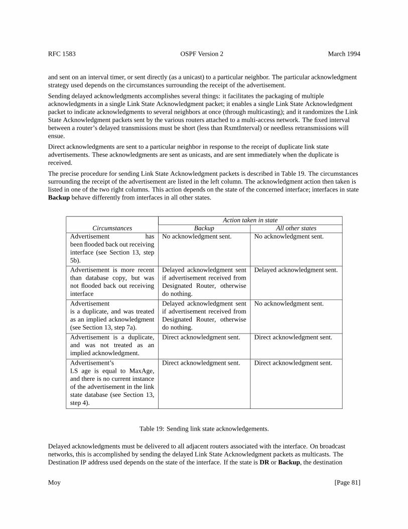
RFC 1583 OSPF Version 2 March 1994
and sent on an interval timer, or sent directly (as a unicast) to a particular neighbor. The particular acknowledgmentstrategy used depends on the circumstances surrounding the receipt of the advertisement.
Sending delayed acknowledgments accomplishes several things: it facilitates the packaging of multipleacknowledgments in a single Link State Acknowledgment packet; it enables a single Link State Acknowledgmentpacket to indicate acknowledgments to several neighbors at once (through multicasting); and it randomizes the LinkState Acknowledgment packets sent by the various routers attached to a multi-access network. The fixed intervalbetween a router’s delayed transmissions must be short (less than RxmtInterval) or needless retransmissions willensue.
Direct acknowledgments are sent to a particular neighbor in response to the receipt of duplicate link stateadvertisements. These acknowledgments are sent as unicasts, and are sent immediately when the duplicate isreceived.
The precise procedure for sending Link State Acknowledgment packets is described in Table 19. The circumstancessurrounding the receipt of the advertisement are listed in the left column. The acknowledgment action then taken islisted in one of the two right columns. This action depends on the state of the concerned interface; interfaces in stateBackup behave differently from interfaces in all other states.
Action taken in stateCircumstances Backup All other states
Advertisement hasbeen flooded back out receivinginterface (see Section 13, step5b).
No acknowledgment sent. No acknowledgment sent.
Advertisement is more recentthan database copy, but wasnot flooded back out receivinginterface
Delayed acknowledgment sentif advertisement received fromDesignated Router, otherwisedo nothing.
Delayed acknowledgment sent.
Advertisementis a duplicate, and was treatedas an implied acknowledgment(see Section 13, step 7a).
Delayed acknowledgment sentif advertisement received fromDesignated Router, otherwisedo nothing.
No acknowledgment sent.
Advertisement is a duplicate,and was not treated as animplied acknowledgment.
Direct acknowledgment sent. Direct acknowledgment sent.
Advertisement’sLS age is equal to MaxAge,and there is no current instanceof the advertisement in the linkstate database (see Section 13,step 4).
Direct acknowledgment sent. Direct acknowledgment sent.
Table 19: Sending link state acknowledgements.
Delayed acknowledgments must be delivered to all adjacent routers associated with the interface. On broadcastnetworks, this is accomplished by sending the delayed Link State Acknowledgment packets as multicasts. TheDestination IP address used depends on the state of the interface. If the state isDR or Backup, the destination
Moy [Page 81]
RFC 1583 OSPF Version 2 March 1994
AllSPFRouters is used. In other states, the destination AllDRouters is used. On non-broadcast networks, delayedLink State Acknowledgment packets must be unicast separately over each adjacency (i.e., neighbor whose state is>= Exchange).
The reasoning behind sending the above packets as multicasts is best explained by an example. Consider the networkconfiguration depicted in Figure 15. Suppose RT4 has been elected as Designated Router, and RT3 as BackupDesignated Router for the network N3. When Router RT4 floods a new advertisement to Network N3, it is receivedby routers RT1, RT2, and RT3. These routers will not flood the advertisement back onto net N3, but they still mustensure that their topological databases remain synchronized with their adjacent neighbors. So RT1, RT2, and RT4 arewaiting to see an acknowledgment from RT3. Likewise, RT4 and RT3 are both waiting to see acknowledgmentsfrom RT1 and RT2. This is best achieved by sending the acknowledgments as multicasts.
The reason that the acknowledgment logic for Backup DRs is slightly different is because they perform differentlyduring the flooding of link state advertisements (see Section 13.3, step 4).
13.6 Retransmitting link state advertisements
Advertisements flooded out an adjacency are placed on the adjacency’sLink state retransmission list. In order toensure that flooding is reliable, these advertisements are retransmitted until they are acknowledged. The length oftime between retransmissions is a configurable per-interface value, RxmtInterval. If this is set too low for aninterface, needless retransmissions will ensue. If the value is set too high, the speed of the flooding, in the face of lostpackets, may be affected.
Several retransmitted advertisements may fit into a single Link State Update packet. When advertisements are to beretransmitted, only the number fitting in a single Link State Update packet should be transmitted. Another packet ofretransmissions can be sent when some of the advertisements are acknowledged, or on the next firing of theretransmission timer.
Link State Update Packets carrying retransmissions are always sent as unicasts (directly to the physical address ofthe neighbor). They are never sent as multicasts. Each advertisement’s LS age must be incremented byInfTransDelay (which must be>0) when copied into the outgoing Link State Update packet (until the LS age fieldreaches its maximum value of MaxAge).
If the adjacent router goes down, retransmissions may occur until the adjacency is destroyed by OSPF’s HelloProtocol. When the adjacency is destroyed, theLink state retransmission list is cleared.
13.7 Receiving link state acknowledgments
Many consistency checks have been made on a received Link State Acknowledgment packet before it is handed tothe flooding procedure. In particular, it has been associated with a particular neighbor. If this neighbor is in a lesserstate thanExchange, the Link State Acknowledgment packet is discarded.
Otherwise, for each acknowledgment in the Link State Acknowledgment packet, the following steps are performed:
� Does the advertisement acknowledged have an instance on theLink state retransmission list for theneighbor? If not, examine the next acknowledgment. Otherwise:
� If the acknowledgment is for the same instance that is contained on the list, remove the item from the list andexamine the next acknowledgment. Otherwise:
� Log the questionable acknowledgment, and examine the next one.
Moy [Page 82]
RFC 1583 OSPF Version 2 March 1994
14 Aging The Link State Database
Each link state advertisement has an LS age field. The LS age is expressed in seconds. An advertisement’s LS agefield is incremented while it is contained in a router’s database. Also, when copied into a Link State Update Packetfor flooding out a particular interface, the advertisement’s LS age is incremented by InfTransDelay.
An advertisement’s LS age is never incremented past the value MaxAge. Advertisements having age MaxAge are notused in the routing table calculation. As a router ages its link state database, an advertisement’s LS age may reachMaxAge. 18 At this time, the router must attempt to flush the advertisement from the routing domain. This is donesimply by reflooding the MaxAge advertisement just as if it was a newly originated advertisement (see Section 13.3).
When creating aDatabase summary listfor a newly forming adjacency, any MaxAge advertisements present in thelink state database are added to the neighbor’sLink state retransmission list instead of the neighbor’sDatabasesummary list. See Section 10.3 for more details.
A MaxAge advertisement must be removed immediately from the router’s link state database as soon as both a) it isno longer contained on any neighborLink state retransmission listsand b) none of the router’s neighbors are instatesExchangeor Loading.
When, in the process of aging the link state database, an advertisement’s LS age hits a multiple of CheckAge, its LSchecksum should be verified. If the LS checksum is incorrect, a program or memory error has been detected, and atthe very least the router itself should be restarted.
14.1 Premature aging of advertisements
A link state advertisement can be flushed from the routing domain by setting its LS age to MaxAge and refloodingthe advertisement. This procedure follows the same course as flushing an advertisement whose LS age has naturallyreached the value MaxAge (see Section 14). In particular, the MaxAge advertisement is removed from the router’slink state database as soon as a) it is no longer contained on any neighborLink state retransmission listsand b)none of the router’s neighbors are in statesExchangeor Loading. We call the setting of an advertisement’s LS ageto MaxAgepremature aging.
Premature aging is used when it is time for a self-originated advertisement’s sequence number field to wrap. At thispoint, the current advertisement instance (having LS sequence number of0x7fffffff ) must be prematurely agedand flushed from the routing domain before a new instance with sequence number0x80000001 can be originated.See Section 12.1.6 for more information.
Premature aging can also be used when, for example, one of the router’s previously advertised external routes is nolonger reachable. In this circumstance, the router can flush its external advertisement from the routing domain viapremature aging. This procedure is preferable to the alternative, which is to originate a new advertisement for thedestination specifying a metric of LSInfinity. Premature aging is also be used when unexpectedly receivingself-originated advertisements during the flooding procedure (see Section 13.4.
A router may only prematurely age its own self-originated link state advertisements. The router may not prematurelyage advertisements that have been originated by other routers. An advertisement is considered self-originated wheneither 1) the advertisement’s Advertising Router is equal to the router’s own Router ID or 2) the advertisement is anetwork links advertisement and its Link State ID is equal to one of the router’s own IP interface addresses.
18It should be a relatively rare occurrence for an advertisement’s LS age to reach MaxAge in this fashion. Usually, the advertisement will bereplaced by a more recent instance before it ages out.
Moy [Page 83]
RFC 1583 OSPF Version 2 March 1994
15 Virtual Links
The single backbone area (Area ID =0.0.0.0 ) cannot be disconnected, or some areas of the Autonomous Systemwill become unreachable. To establish/maintain connectivity of the backbone, virtual links can be configuredthrough non-backbone areas. Virtual links serve to connect physically separate components of the backbone. Thetwo endpoints of a virtual link are area border routers. The virtual link must be configured in both routers. Theconfiguration information in each router consists of the other virtual endpoint (the other area border router), and thenon-backbone area the two routers have in common (called the transit area). Virtual links cannot be configuredthrough stub areas (see Section 3.6).
The virtual link is treated as if it were an unnumbered point-to-point network (belonging to the backbone) joining thetwo area border routers. An attempt is made to establish an adjacency over the virtual link. When this adjacency isestablished, the virtual link will be included in backbone router links advertisements, and OSPF packets pertaining tothe backbone area will flow over the adjacency. Such an adjacency has been referred to in this document as a “virtualadjacency”.
In each endpoint router, the cost and viability of the virtual link is discovered by examining the routing table entryfor the other endpoint router. (The entry’s associated area must be the configured transit area). Actually, there may bea separate routing table entry for each Type of Service. These are called the virtual link’s corresponding routing tableentries. TheInterfaceUp event occurs for a virtual link when its corresponding TOS 0 routing table entry becomesreachable. Conversely, theInterfaceDown event occurs when its TOS 0 routing table entry becomes unreachable.19
In other words, the virtual link’s viability is determined by the existence of an intra-area path, through the transitarea, between the two endpoints. Note that a virtual link whose underlying path has cost greater than hexadecimal0xffff (the maximum size of an interface cost in a router links advertisement) should be considered inoperational(i.e., treated the same as if the path did not exist).
The other details concerning virtual links are as follows:
� AS external links are NEVER flooded over virtual adjacencies. This would be duplication of effort, since thesame AS external links are already flooded throughout the virtual link’s transit area. For this same reason, ASexternal link advertisements are not summarized over virtual adjacencies during the Database Exchangeprocess.
� The cost of a virtual link is NOT configured. It is defined to be the cost of the intra-area path between the twodefining area border routers. This cost appears in the virtual link’s corresponding routing table entry. When thecost of a virtual link changes, a new router links advertisement should be originated for the backbone area.
� Just as the virtual link’s cost and viability are determined by the routing table build process (throughconstruction of the routing table entry for the other endpoint), so are the IP interface address for the virtualinterface and the virtual neighbor’s IP address. These are used when sending OSPF protocol packets over thevirtual link. Note that when one (or both) of the virtual link endpoints connect to the transit area via anunnumbered point-to-point link, it may be impossible to calculate either the virtual interface’s IP addressand/or the virtual neighbor’s IP address, thereby causing the virtual link to fail.
� In each endpoint’s router links advertisement for the backbone, the virtual link is represented as aType 4 linkwhoseLink ID is set to the virtual neighbor’s OSPF Router ID and whoseLink Data is set to the virtualinterface’s IP address. See Section 12.4.1 for more information. Note that it may be the case that there is a TOS0 path, but no non-zero TOS paths, between the two endpoint routers. In this case, both routers must revert tobeing non-TOS-capable, clearing theT-bit in theOptions field of their backbone router links advertisements.
19Only the TOS 0 routes are important here because all OSPF protocol packets are sent with TOS= 0. See Appendix A.
Moy [Page 84]
RFC 1583 OSPF Version 2 March 1994
� When virtual links are configured for the backbone, information concerning backbone networks should not becondensed before being summarized into the transit areas. In other words, each backbone network should beadvertised into the transit areas in a separate summary link advertisement, regardless of the backbone’sconfiguredarea address ranges. See Section 12.4.3 for more information.
� The time between link state retransmissions, RxmtInterval, is configured for a virtual link. This should be wellover the expected round-trip delay between the two routers. This may be hard to estimate for a virtual link; it isbetter to err on the side of making it too large.
16 Calculation Of The Routing Table
This section details the OSPF routing table calculation. Using its attached areas’ link state databases as input, arouter runs the following algorithm, building its routing table step by step. At each step, the router must accessindividual pieces of the link state databases (e.g., a router links advertisement originated by a certain router). Thisaccess is performed by the lookup function discussed in Section 12.2. The lookup process may return a link stateadvertisement whose LS age is equal to MaxAge. Such an advertisement should not be used in the routing tablecalculation, and is treated just as if the lookup process had failed.
The OSPF routing table’s organization is explained in Section 11. Two examples of the routing table build processare presented in Sections 11.2 and 11.3. This process can be broken into the following steps:
1. The present routing table is invalidated.The routing table is built again from scratch. The old routing table issaved so that changes in routing table entries can be identified.
2. The intra-area routes are calculated by building the shortest-path tree for each attached area.In particular, allrouting table entries whose Destination Type is “area border router” are calculated in this step. This step isdescribed in two parts. At first the tree is constructed by only considering those links between routers andtransit networks. Then the stub networks are incorporated into the tree. During the area’s shortest-path treecalculation, the area’sTransitCapability is also calculated for later use in Step 4.
3. The inter-area routes are calculated, through examination of summary link advertisements.If the router isattached to multiple areas (i.e., it is an area border router), only backbone summary link advertisements areexamined.
4. In area border routers connecting to one or more transit areas(i.e, non-backbone areas whoseTransitCapability is found to be TRUE), the transit areas’ summary link advertisements are examined to seewhether better paths exist using the transit areas than were found in Steps 2-3 above.
5. Routes to external destinations are calculated, through examination of AS external link advertisements.Thelocations of the AS boundary routers (which originate the AS external link advertisements) have beendetermined in steps 2-4.
Steps 2-5 are explained in further detail below. The explanations describe the calculations for TOS 0 only. It mayalso be necessary to perform each step (separately) for each of the non-zero TOS values.20 For more informationconcerning the building of non-zero TOS routes see Section 16.9.
Changes made to routing table entries as a result of these calculations can cause the OSPF protocol to take furtheractions. For example, a change to an intra-area route will cause an area border router to originate new summary linkadvertisements (see Section 12.4). See Section 16.7 for a complete list of the OSPF protocol actions resulting fromrouting table changes.
20It may be the case that paths to certain destinations do not vary based on TOS. For these destinations, the routing calculation need not berepeated for each TOS value. In addition, there need only be a single routing table entry for these destinations (instead of a separate entry for eachTOS value).
Moy [Page 85]
RFC 1583 OSPF Version 2 March 1994
16.1 Calculating the shortest-path tree for an area
This calculation yields the set of intra-area routes associated with an area (called hereafter Area A). A routercalculates the shortest-path tree using itself as the root.21 The formation of the shortest path tree is done here in twostages. In the first stage, only links between routers and transit networks are considered. Using the Dijkstraalgorithm, a tree is formed from this subset of the link state database. In the second stage, leaves are added to the treeby considering the links to stub networks.
The procedure will be explained using the graph terminology that was introduced in Section 2. The area’s link statedatabase is represented as a directed graph. The graph’s vertices are routers, transit networks and stub networks. Thefirst stage of the procedure concerns only the transit vertices (routers and transit networks) and their connecting links.Throughout the shortest path calculation, the following data is also associated with each transit vertex:
Vertex (node) ID A 32-bit number uniquely identifying the vertex. For router vertices this is the router’s OSPFRouter ID. For network vertices, this is the IP address of the network’s Designated Router.
A link state advertisement Each transit vertex has an associated link state advertisement. For router vertices, this isa router links advertisement. For transit networks, this is a network links advertisement (which is actuallyoriginated by the network’s Designated Router). In any case, the advertisement’s Link State ID is always equalto the above Vertex ID.
List of next hops The list of next hops for the current set of shortest paths from the root to this vertex. There can bemultiple shortest paths due to the equal-cost multipath capability. Each next hop indicates the outgoing routerinterface to use when forwarding traffic to the destination. On multi-access networks, the next hop alsoincludes the IP address of the next router (if any) in the path towards the destination.
Distance from root The link state cost of the current set of shortest paths from the root to the vertex. The link statecost of a path is calculated as the sum of the costs of the path’s constituent links (as advertised in router linksand network links advertisements). One path is said to be “shorter” than another if it has a smaller link statecost.
The first stage of the procedure (i.e., the Dijkstra algorithm) can now be summarized as follows. At each iteration ofthe algorithm, there is a list of candidate vertices. Paths from the root to these vertices have been found, but notnecessarily the shortest ones. However, the paths to the candidate vertex that is closest to the root are guaranteed tobe shortest; this vertex is added to the shortest-path tree, removed from the candidate list, and its adjacent vertices areexamined for possible addition to/modification of the candidate list. The algorithm then iterates again. It terminateswhen the candidate list becomes empty.
The following steps describe the algorithm in detail. Remember that we are computing the shortest path tree for AreaA. All references to link state database lookup below are from Area A’s database.
1. Initialize the algorithm’s data structures. Clear the list of candidate vertices. Initialize the shortest-path tree toonly the root (which is the router doing the calculation). Set Area A’sTransitCapability to FALSE.
2. Call the vertex just added to the tree vertex V. Examine the link state advertisement associated with vertex V.This is a lookup in the Area A’s link state database based on theVertex ID . If this is a router linksadvertisement, andbit V of the router links advertisement (see Section A.4.2) is set, set Area A’sTransitCapability to TRUE. In any case, each link described by the advertisement gives the cost to anadjacent vertex. For each described link, (say it joins vertex V to vertex W):
21Strictly speaking, because of equal-cost multipath, the algorithm does not create a tree. We continue to use the “tree” terminology because thatis what occurs most often in the existing literature.
Moy [Page 86]
RFC 1583 OSPF Version 2 March 1994
(a) If this is a link to a stub network, examine the next link in V’s advertisement. Links to stub networks willbe considered in the second stage of the shortest path calculation.
(b) Otherwise, W is a transit vertex (router or transit network). Look up the vertex W’s link stateadvertisement (router links or network links) in Area A’s link state database. If the advertisement doesnot exist, or its LS age is equal to MaxAge, or it does not have a link back to vertex V, examine the nextlink in V’s advertisement.22
(c) If vertex W is already on the shortest-path tree, examine the next link in the advertisement.
(d) Calculate the link state cost D of the resulting path from the root to vertex W. D is equal to the sum of thelink state cost of the (already calculated) shortest path to vertex V and the advertised cost of the linkbetween vertices V and W. If D is:
� Greater than the value that already appears for vertex W on the candidate list, then examine the nextlink.
� Equal to the value that appears for vertex W on the candidate list, calculate the set of next hops thatresult from using the advertised link. Input to this calculation is the destination (W), and its parent(V). This calculation is shown in Section 16.1.1. This set of hops should be added to the next hopvalues that appear for W on the candidate list.
� Less than the value that appears for vertex W on the candidate list, or if W does not yet appear on thecandidate list, then set the entry for W on the candidate list to indicate a distance of D from the root.Also calculate the list of next hops that result from using the advertised link, setting the next hopvalues for W accordingly. The next hop calculation is described in Section 16.1.1; it takes as inputthe destination (W) and its parent (V).
3. If at this step the candidate list is empty, the shortest-path tree (of transit vertices) has been completely builtand this stage of the procedure terminates. Otherwise, choose the vertex belonging to the candidate list that isclosest to the root, and add it to the shortest-path tree (removing it from the candidate list in the process). Notethat when there is a choice of vertices closest to the root, network vertices must be chosen before routervertices in order to necessarily find all equal-cost paths. This is consistent with the tie-breakers that wereintroduced in the modified Dijkstra algorithm used by OSPF’s Multicast routing extensions (MOSPF).
4. Possibly modify the routing table. For those routing table entries modified, the associated area will be set toArea A, the path type will be set to intra-area, and the cost will be set to the newly discovered shortest path’scalculated distance.
If the newly added vertex is an area border router (call it ABR), a routing table entry is added whosedestination type is “area border router”. TheOptions field found in the associated router links advertisement iscopied into the routing table entry’sOptional capabilities field. If in addition ABR is the endpoint of one ofthe calculating router’s configured virtual links that uses Area A as its Transit area: the virtual link is declaredup, the IP address of the virtual interface is set to the IP address of the outgoing interface calculated above forABR, and the virtual neighbor’s IP address is set to the ABR interface address (contained in ABR’s routerlinks advertisement) that points back to the root of the shortest-path tree; equivalently, this is the interface thatpoints back to ABR’s parent vertex on the shortest-path tree (similar to the calculation in Section 16.1.1).
If the newly added vertex is an AS boundary router, the routing table entry of type “AS boundary router” forthe destination is located. Since routers can belong to more than one area, it is possible that several sets ofintra-area paths exist to the AS boundary router, each set using a different area. However, the AS boundaryrouter’s routing table entry must indicate a set of paths which utilize a single area. The area leading to therouting table entry is selected as follows: The area providing the shortest path is always chosen; if more than
22Note that the presence of any link back to V is sufficient; it need not be the matching half of the link under consideration from V to W. This isenough to ensure that, before data traffic flows between a pair of neighboring routers, their link state databases will be synchronized.
Moy [Page 87]
RFC 1583 OSPF Version 2 March 1994
one area provides paths with the same minimum cost, the area with the largest OSPF Area ID (whenconsidered as an unsigned 32-bit integer) is chosen. Note that whenever an AS boundary router’s routing tableentry is added/modified, theOptions found in the associated router links advertisement is copied into therouting table entry’sOptional capabilities field.
If the newly added vertex is a transit network, the routing table entry for the network is located. The entry’sDestination ID is the IP network number, which can be obtained by masking theVertex ID (Link State ID)with its associated subnet mask (found in the body of the associated network links advertisement). If therouting table entry already exists (i.e., there is already an intra-area route to the destination installed in therouting table), multiple vertices have mapped to the same IP network. For example, this can occur when a newDesignated Router is being established. In this case, the current routing table entry should be overwritten ifand only if the newly found path is just as short and the current routing table entry’sLink State Origin has asmaller Link State ID than the newly added vertex’link state advertisement.
If there is no routing table entry for the network (the usual case), a routing table entry for the IP networkshould be added. The routing table entry’sLink State Origin should be set to the newly added vertex’linkstate advertisement.
5. Iterate the algorithm by returning to Step 2.
The stub networks are added to the tree in the procedure’s second stage. In this stage, all router vertices are againexamined. Those that have been determined to be unreachable in the above first phase are discarded. For eachreachable router vertex (call it V), the associated router links advertisement is found in the link state database. Eachstub network link appearing in the advertisement is then examined, and the following steps are executed:
1. Calculate the distance D of stub network from the root. D is equal to the distance from the root to the routervertex (calculated in stage 1), plus the stub network link’s advertised cost. Compare this distance to the currentbest cost to the stub network. This is done by looking up the stub network’s current routing table entry. If thecalculated distance D is larger, go on to examine the next stub network link in the advertisement.
2. If this step is reached, the stub network’s routing table entry must be updated. Calculate the set of next hopsthat would result from using the stub network link. This calculation is shown in Section 16.1.1; input to thiscalculation is the destination (the stub network) and the parent vertex (the router vertex). If the distance D isthe same as the current routing table cost, simply add this set of next hops to the routing table entry’s list ofnext hops. In this case, the routing table already has aLink State Origin . If this Link State Origin is a routerlinks advertisement whose Link State ID is smaller than V’s Router ID, reset theLink State Origin to V’srouter links advertisement.
Otherwise D is smaller than the routing table cost. Overwrite the current routing table entry by setting therouting table entry’s cost to D, and by setting the entry’s list of next hops to the newly calculated set. Set therouting table entry’sLink State Origin to V’s router links advertisement. Then go on to examine the next stubnetwork link.
For all routing table entries added/modified in the second stage, the associated area will be set to Area A and the pathtype will be set to intra-area. When the list of reachable router links is exhausted, the second stage is completed. Atthis time, all intra-area routes associated with Area A have been determined.
The specification does not require that the above two stage method be used to calculate the shortest path tree.However, if another algorithm is used, an identical tree must be produced. For this reason, it is important to note thatlinks between transit vertices must be bidirectional in ordered to be included in the above tree. It should also bementioned that more efficient algorithms exist for calculating the tree; for example, the incremental SPF algorithmdescribed in [BBN].
Moy [Page 88]
RFC 1583 OSPF Version 2 March 1994
16.1.1 The next hop calculation
This section explains how to calculate the current set of next hops to use for a destination. Each next hop consists ofthe outgoing interface to use in forwarding packets to the destination together with the next hop router (if any). Thenext hop calculation is invoked each time a shorter path to the destination is discovered. This can happen in eitherstage of the shortest-path tree calculation (see Section 16.1). In stage 1 of the shortest-path tree calculation a shorterpath is found as the destination is added to the candidate list, or when the destination’s entry on the candidate list ismodified (Step 2d of Stage 1). In stage 2 a shorter path is discovered each time the destination’s routing table entry ismodified (Step 2 of Stage 2).
The set of next hops to use for the destination may be recalculated several times during the shortest-path treecalculation, as shorter and shorter paths are discovered. In the end, the destination’s routing table entry will alwaysreflect the next hops resulting from the absolute shortest path(s).
Input to the next hop calculation is a) the destination and b) its parent in the current shortest path between the root(the calculating router) and the destination. The parent is always a transit vertex (i.e., always a router or a transitnetwork).
If there is at least one intervening router in the current shortest path between the destination and the root, thedestination simply inherits the set of next hops from the parent. Otherwise, there are two cases. In the first case, theparent vertex is the root (the calculating router itself). This means that the destination is either a directly connectednetwork or directly connected router. The next hop in this case is simply the OSPF interface connecting to thenetwork/router; no next hop router is required. If the connecting OSPF interface in this case is a virtual link, thesetting of the next hop should be deferred until the calculation in Section 16.3.
In the second case, the parent vertex is a network that directly connects the calculating router to the destinationrouter. The list of next hops is then determined by examining the destination’s router links advertisement. For eachlink in the advertisement that points back to the parent network, the link’s Link Data field provides the IP address ofa next hop router. The outgoing interface to use can then be derived from the next hop IP address (or it can beinherited from the parent network).
16.2 Calculating the inter-area routes
The inter-area routes are calculated by examining summary link advertisements. If the router has active attachmentsto multiple areas, only backbone summary link advertisements are examined. Routers attached to a single areaexamine that area’s summary links. In either case, the summary links examined below are all part of a single area’slink state database (call it Area A).
Summary link advertisements are originated by the area border routers. Each summary link advertisement in Area Ais considered in turn. Remember that the destination described by a summary link advertisement is either a network(Type 3 summary link advertisements) or an AS boundary router (Type 4 summary link advertisements). For eachsummary link advertisement:
1. If the cost specified by the advertisement is LSInfinity, or if the advertisement’s LS age is equal to MaxAge,then examine the next advertisement.
2. If the advertisement was originated by the calculating router itself, examine the next advertisement.
3. If the collection of destinations described by the summary link advertisement falls into one of the router’sconfiguredarea address ranges(see Section 3.5) and the particulararea address rangeis active, thesummary link advertisement should be ignored. Active means that there are one or more reachable (byintra-area paths) networks contained in the area range. In this case, all addresses in the area range are assumedto be either reachable via intra-area paths, or else to be unreachable by any other means.
Moy [Page 89]
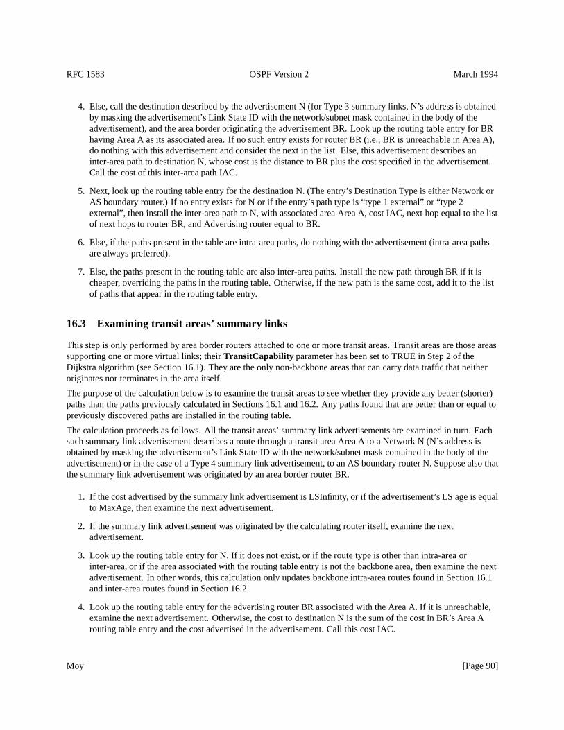
RFC 1583 OSPF Version 2 March 1994
4. Else, call the destination described by the advertisement N (for Type 3 summary links, N’s address is obtainedby masking the advertisement’s Link State ID with the network/subnet mask contained in the body of theadvertisement), and the area border originating the advertisement BR. Look up the routing table entry for BRhaving Area A as its associated area. If no such entry exists for router BR (i.e., BR is unreachable in Area A),do nothing with this advertisement and consider the next in the list. Else, this advertisement describes aninter-area path to destination N, whose cost is the distance to BR plus the cost specified in the advertisement.Call the cost of this inter-area path IAC.
5. Next, look up the routing table entry for the destination N. (The entry’s Destination Type is either Network orAS boundary router.) If no entry exists for N or if the entry’s path type is “type 1 external” or “type 2external”, then install the inter-area path to N, with associated area Area A, cost IAC, next hop equal to the listof next hops to router BR, and Advertising router equal to BR.
6. Else, if the paths present in the table are intra-area paths, do nothing with the advertisement (intra-area pathsare always preferred).
7. Else, the paths present in the routing table are also inter-area paths. Install the new path through BR if it ischeaper, overriding the paths in the routing table. Otherwise, if the new path is the same cost, add it to the listof paths that appear in the routing table entry.
16.3 Examining transit areas’ summary links
This step is only performed by area border routers attached to one or more transit areas. Transit areas are those areassupporting one or more virtual links; theirTransitCapability parameter has been set to TRUE in Step 2 of theDijkstra algorithm (see Section 16.1). They are the only non-backbone areas that can carry data traffic that neitheroriginates nor terminates in the area itself.
The purpose of the calculation below is to examine the transit areas to see whether they provide any better (shorter)paths than the paths previously calculated in Sections 16.1 and 16.2. Any paths found that are better than or equal topreviously discovered paths are installed in the routing table.
The calculation proceeds as follows. All the transit areas’ summary link advertisements are examined in turn. Eachsuch summary link advertisement describes a route through a transit area Area A to a Network N (N’s address isobtained by masking the advertisement’s Link State ID with the network/subnet mask contained in the body of theadvertisement) or in the case of a Type 4 summary link advertisement, to an AS boundary router N. Suppose also thatthe summary link advertisement was originated by an area border router BR.
1. If the cost advertised by the summary link advertisement is LSInfinity, or if the advertisement’s LS age is equalto MaxAge, then examine the next advertisement.
2. If the summary link advertisement was originated by the calculating router itself, examine the nextadvertisement.
3. Look up the routing table entry for N. If it does not exist, or if the route type is other than intra-area orinter-area, or if the area associated with the routing table entry is not the backbone area, then examine the nextadvertisement. In other words, this calculation only updates backbone intra-area routes found in Section 16.1and inter-area routes found in Section 16.2.
4. Look up the routing table entry for the advertising router BR associated with the Area A. If it is unreachable,examine the next advertisement. Otherwise, the cost to destination N is the sum of the cost in BR’s Area Arouting table entry and the cost advertised in the advertisement. Call this cost IAC.
Moy [Page 90]
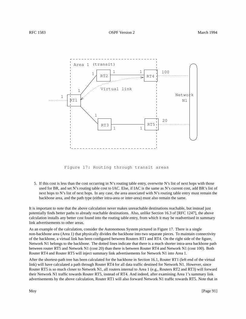
RFC 1583 OSPF Version 2 March 1994
N1Network1
(transit)
Virtual link
Figure 17: Routing through transit areas
100
20
11
1
111
1
Area 1
RT1
RT2
RT3
RT4
RT5
5. If this cost is less than the cost occurring in N’s routing table entry, overwrite N’s list of next hops with thoseused for BR, and set N’s routing table cost to IAC. Else, if IAC is the same as N’s current cost, add BR’s list ofnext hops to N’s list of next hops. In any case, the area associated with N’s routing table entry must remain thebackbone area, and the path type (either intra-area or inter-area) must also remain the same.
It is important to note that the above calculation never makes unreachable destinations reachable, but instead justpotentially finds better paths to already reachable destinations. Also, unlike Section 16.3 of [RFC 1247], the abovecalculation installs any better cost found into the routing table entry, from which it may be readvertised in summarylink advertisements to other areas.
As an example of the calculation, consider the Autonomous System pictured in Figure 17. There is a singlenon-backbone area (Area 1) that physically divides the backbone into two separate pieces. To maintain connectivityof the backbone, a virtual link has been configured between Routers RT1 and RT4. On the right side of the figure,Network N1 belongs to the backbone. The dotted lines indicate that there is a much shorter intra-area backbone pathbetween router RT5 and Network N1 (cost 20) than there is between Router RT4 and Network N1 (cost 100). BothRouter RT4 and Router RT5 will inject summary link advertisements for Network N1 into Area 1.
After the shortest-path tree has been calculated for the backbone in Section 16.1, Router RT1 (left end of the virtuallink) will have calculated a path through Router RT4 for all data traffic destined for Network N1. However, sinceRouter RT5 is so much closer to Network N1, all routers internal to Area 1 (e.g., Routers RT2 and RT3) will forwardtheir Network N1 traffic towards Router RT5, instead of RT4. And indeed, after examining Area 1’s summary linkadvertisements by the above calculation, Router RT1 will also forward Network N1 traffic towards RT5. Note that in
Moy [Page 91]
RFC 1583 OSPF Version 2 March 1994
this example the virtual link enables Network N1 traffic to be forwarded through the transit area Area 1, but theactual path the data traffic takes does not follow the virtual link. In other words, virtual links allow transit traffic to beforwarded through an area, but do not dictate the precise path that the traffic will take.
16.4 Calculating AS external routes
AS external routes are calculated by examining AS external link advertisements. Each of the AS external linkadvertisements is considered in turn. Most AS external link advertisements describe routes to specific IP destinations.An AS external link advertisement can also describe a default route for the Autonomous System (Destination ID=
DefaultDestination, network/subnet mask= 0x00000000 ). For each AS external link advertisement:
1. If the cost specified by the advertisement is LSInfinity, or if the advertisement’s LS age is equal to MaxAge,then examine the next advertisement.
2. If the advertisement was originated by the calculating router itself, examine the next advertisement.
3. Call the destination described by the advertisement N. N’s address is obtained by masking the advertisement’sLink State ID with the network/subnet mask contained in the body of the advertisement. Look up the routingtable entry for the AS boundary router (ASBR) that originated the advertisement. If no entry exists for routerASBR (i.e., ASBR is unreachable), do nothing with this advertisement and consider the next in the list.
Else, this advertisement describes an AS external path to destination N. Examine theforwarding addressspecified in the external advertisement. This indicates the IP address to which packets for the destinationshould be forwarded. Ifforwarding address is set to0.0.0.0 , packets should be sent to the ASBR itself.Otherwise, look up theforwarding address in the routing table.23 An intra-area or inter-area path must existto the forwarding address. If no such path exists, do nothing with the advertisement and consider the next inthe list.
Call the routing table distance to theforwarding addressX (when the forwarding address is set to0.0.0.0 ,this is the distance to the ASBR itself), and the cost specified in the advertisement Y. X is in terms of the linkstate metric, and Y is a type 1 or 2 external metric.
4. Next, look up the routing table entry for the destination N. If no entry exists for N, install the AS external pathto N, with next hop equal to the list of next hops to theforwarding address, and advertising router equal toASBR. If the external metric type is 1, then the path-type is set to type 1 external and the cost is equal to X+Y.If the external metric type is 2, the path-type is set to type 2 external, the link state component of the route’scost is X, and the type 2 cost is Y.
5. Else, if the paths present in the table are not type 1 or type 2 external paths, do nothing (AS external paths havethe lowest priority).
6. Otherwise, compare the cost of this new AS external path to the ones present in the table. Type 1 externalpaths are always shorter than type 2 external paths. Type 1 external paths are compared by looking at the sumof the distance to theforwarding addressand the advertised type 1 metric (X+Y). Type 2 external paths arecompared by looking at the advertised type 2 metrics, and then if necessary, the distance to theforwardingaddresses.
If the new path is shorter, it replaces the present paths in the routing table entry. If the new path is the samecost, it is added to the routing table entry’s list of paths.
23When theforwarding address is non-zero, it should point to a router belonging to another Autonomous System. See Section 12.4.5 for moredetails.
Moy [Page 92]
RFC 1583 OSPF Version 2 March 1994
16.5 Incremental updates — summary link advertisements
When a new summary link advertisement is received, it is not necessary to recalculate the entire routing table. Callthe destination described by the summary link advertisement N (N’s address is obtained by masking theadvertisement’s Link State ID with the network/subnet mask contained in the body of the advertisement), and letArea A be the area to which the advertisement belongs. There are then two separate cases:
Case 1: Area A is the backbone and/or the router is not an area border router.In this case, the followingcalculations must be performed. First, if there is presently an inter-area route to the destination N, N’s routingtable entry is invalidated, saving the entry’s values for later comparisons. Then the calculation in Section 16.2is run again for the single destination N. In this calculation, all of Area A’s summary link advertisements thatdescribe a route to N are examined. In addition, if the router is an area border router attached to one or moretransit areas, the calculation in Section 16.3 must be run again for the single destination. If the results of thesecalculations have changed the cost/path to an AS boundary router (as would be the case for a Type 4 summarylink advertisement) or to any forwarding addresses, all AS external link advertisements will have to bereexamined by rerunning the calculation in Section 16.4. Otherwise, if N is now newly unreachable, thecalculation in Section 16.4 must be rerun for the single destination N, in case an alternate external route to Nexists.
Case 2: Area A is a transit area and the router is an area border router.In this case, the following calculationsmust be performed. First, if N’s routing table entry presently contains one or more inter-area paths that utilizethe transit area Area A, these paths should be removed. If this removes all paths from the routing table entry,the entry should be invalidated. The entry’s old values should be saved for later comparisons. Next thecalculation in Section 16.3 must be run again for the single destination N. If the results of this calculation havecaused the cost to N to increase, the complete routing table calculation must be rerun starting with the Dijkstraalgorithm specified in Section 16.1. Otherwise, if the cost/path to an AS boundary router (as would be the casefor a Type 4 summary link advertisement) or to any forwarding addresses has changed, all AS external linkadvertisements will have to be reexamined by rerunning the calculation in Section 16.4. Otherwise, if N is nownewly unreachable, the calculation in Section 16.4 must be rerun for the single destination N, in case analternate external route to N exists.
16.6 Incremental updates — AS external link advertisements
When a new AS external link advertisement is received, it is not necessary to recalculate the entire routing table. Callthe destination described by the AS external link advertisement N. N’s address is obtained by masking theadvertisement’s Link State ID with the network/subnet mask contained in the body of the advertisement. If there isalready an intra-area or inter-area route to the destination, no recalculation is necessary (internal routes takeprecedence).
Otherwise, the procedure in Section 16.4 will have to be performed, but only for those AS external linkadvertisements whose destination is N. Before this procedure is performed, the present routing table entry for Nshould be invalidated.
16.7 Events generated as a result of routing table changes
Changes to routing table entries sometimes cause the OSPF area border routers to take additional actions. Theserouters need to act on the following routing table changes:
Moy [Page 93]
RFC 1583 OSPF Version 2 March 1994
� The cost or path type of a routing table entry has changed. If the destination described by this entry is aNetwork or AS boundary router, and this is not simply a change of AS external routes, new summary linkadvertisements may have to be generated (potentially one for each attached area, including the backbone). SeeSection 12.4.3 for more information. If a previously advertised entry has been deleted, or is no longeradvertisable to a particular area, the advertisement must be flushed from the routing domain by setting its LSage to MaxAge and reflooding (see Section 14.1).
� A routing table entry associated with a configured virtual link has changed. The destination of such a routingtable entry is an area border router. The change indicates a modification to the virtual link’s cost or viability.
If the entry indicates that the area border router is newly reachable (via TOS 0), the corresponding virtual linkis now operational. AnInterfaceUp event should be generated for the virtual link, which will cause a virtualadjacency to begin to form (see Section 10.3). At this time the virtual link’s IP interface address and the virtualneighbor’s Neighbor IP address are also calculated.
If the entry indicates that the area border router is no longer reachable (via TOS 0), the virtual link and itsassociated adjacency should be destroyed. This means anInterfaceDown event should be generated for theassociated virtual link.
If the cost of the entry has changed, and there is a fully established virtual adjacency, a new router linksadvertisement for the backbone must be originated. This in turn may cause further routing table changes.
16.8 Equal-cost multipath
The OSPF protocol maintains multiple equal-cost routes to all destinations. This can be seen in the steps used aboveto calculate the routing table, and in the definition of the routing table structure.
Each one of the multiple routes will be of the same type (intra-area, inter-area, type 1 external or type 2 external),cost, and will have the same associated area. However, each route specifies a separate next hop and Advertisingrouter.
There is no requirement that a router running OSPF keep track of all possible equal-cost routes to a destination. Animplementation may choose to keep only a fixed number of routes to any given destination. This does not affect anyof the algorithms presented in this specification.
16.9 Building the non-zero-TOS portion of the routing table
The OSPF protocol can calculate a different set of routes for each IP TOS (see Section 2.4). Support for TOS-basedrouting is optional. TOS-capable and non-TOS-capable routers can be mixed in an OSPF routing domain. Routersnot supporting TOS calculate only the TOS 0 route to each destination. These routes are then used to forward all datatraffic, regardless of the TOS indications in the data packet’s IP header. A router that does not support TOS indicatesthis fact to the other OSPF routers by clearing theT-bit in theOptions field of its router links advertisement.
The above sections detailing the routing table calculations handle the TOS 0 case only. In general, for routerssupporting TOS-based routing, each piece of the routing table calculation must be rerun separately for the non-zeroTOS values. When calculating routes for TOS X, only TOS X metrics can be used. Any link state advertisement mayspecify a separate cost for each TOS (a cost for TOS 0 must always be specified). The encoding of TOS in OSPF linkstate advertisements is described in Section 12.3.
An advertisement can specify that it is restricted to TOS 0 (i.e., non-zero TOS is not handled) by clearing theT-bit inthe link state advertisement’sOption field. Such advertisements are not used when calculating routes for non-zeroTOS. For this reason, it is possible that a destination is unreachable for some non-zero TOS. In this case, the TOS 0path is used when forwarding packets (see Section 11.1).
Moy [Page 94]
RFC 1583 OSPF Version 2 March 1994
The following lists the modifications needed when running the routing table calculation for a non-zero TOS value(called TOS X). In general, routers and advertisements that do not support TOS are omitted from the calculation.
Calculating the shortest-path tree (Section 16.1).Routers that do not support TOS-based routing should beomitted from the shortest-path tree calculation. These routers are identified as those having theT-bit reset intheOptions field of their router links advertisements. Such routers should never be added to the Dijktraalgorithm’s candidate list, nor should their router links advertisements be examined when adding the stubnetworks to the tree. In particular, if theT-bit is reset in the calculating router’s own router linksadvertisement, it does not run the shortest-path tree calculation for non-zero TOS values.
Calculating the inter-area routes (Section 16.2).Inter-area paths are the concatenation of a path to an area borderrouter with a summary link. When calculating TOS X routes, both path components must also specify TOS X.In other words, only TOS X paths to the area border router are examined, and the area border router must beadvertising a TOS X route to the destination. Note that this means that summary link advertisements havingtheT-bit reset in theirOptions field are not considered.
Examining transit areas’ summary links (Section 16.3).This calculation again considers the concatenation of apath to an area border router with a summary link. As with inter-area routes, only TOS X paths to the areaborder router are examined, and the area border router must be advertising a TOS X route to the destination.
Calculating AS external routes (Section 16.4).This calculation considers the concatenation of a path to aforwarding addresswith an AS external link. Only TOS X paths to theforwarding addressare examined,and the AS boundary router must be advertising a TOS X route to the destination. Note that this means that ASexternal link advertisements having theT-bit reset in theirOptions field are not considered.
In addition, the advertising AS boundary router must also be reachable for its advertisements to be considered(see Section 16.4). However, if the advertising router and theforwarding addressare not one in the same, theadvertising router need only be reachable via TOS 0.
Moy [Page 95]
RFC 1583 OSPF Version 2 March 1994
References
[BBN] McQuillan, J, I. Richer and E. Rosen,ARPANET Routing Algorithm Improvements, BBN TechnicalReport 3803, April 1978.
[DEC] Digital Equipment Corporation,Information processing systems – Data communications –Intermediate System to Intermediate System Intra-Domain Routing Protocol, October 1987.
[McQuillan] McQuillan, J. et.al.,The New Routing Algorithm for the Arpanet, IEEE Transactions onCommunications, May 1980.
[Perlman] Perlman, R.,Fault-Tolerant Broadcast of Routing Information, Computer Networks, December 1983.
[RFC 791] Postel, J.,Internet Protocol, STD 5, RFC 791, USC/Information Sciences Institute, September 1981.
[RFC 905] McKenzie, A.,ISO Transport Protocol specification ISO DP 8073, RFC 905, ISO, April 1984.
[RFC 1112] Deering, S.,Host extensions for IP multicasting, STD 5, RFC 1112, Stanford University, May 1988.
[RFC 1213] McCloghrie, K., and M. Rose,Management Information Base for network management ofTCP/IP-based internets: MIB-II, STD 17, RFC 1213, Hughes LAN Systems, Performance SystemsInternational, March 1991.
[RFC 1247] Moy, J.,OSPF Version 2, RFC 1247, Proteon, Inc., July 1991.
[RFC 1519] Fuller, V., T. Li, J. Yu, and K. Varadhan,Classless Inter-Domain Routing (CIDR): an AddressAssignment and Aggregation Strategy, RFC1519, BARRNet, cisco, MERIT, OARnet, September 1993.
[RFC 1340] Reynolds, J. and J. Postel,Assigned Numbers, STD 2, RFC 1340, USC/Information Sciences Institute,July 1992.
[RFC 1349] Almquist, P.,Type of Service in the Internet Protocol Suite, RFC 1349, July 1992.
[RS-85-153] Leiner, B., et.al.,The DARPA Internet Protocol Suite, DDN Protocol Handbook, April 1985.
Moy [Page 96]
RFC 1583 OSPF Version 2 March 1994
A OSPF data formats
This appendix describes the format of OSPF protocol packets and OSPF link state advertisements. The OSPFprotocol runs directly over the IP network layer. Before any data formats are described, the details of the OSPFencapsulation are explained.
Next the OSPF Options field is described. This field describes various capabilities that may or may not be supportedby pieces of the OSPF routing domain. The OSPF Options field is contained in OSPF Hello packets, DatabaseDescription packets and in OSPF link state advertisements.
OSPF packet formats are detailed in Section A.3. A description of OSPF link state advertisements appears inSection A.4.
A.1 Encapsulation of OSPF packets
OSPF runs directly over the Internet Protocol’s network layer. OSPF packets are therefore encapsulated solely by IPand local data-link headers.
OSPF does not define a way to fragment its protocol packets, and depends on IP fragmentation when transmittingpackets larger than the network MTU. The OSPF packet types that are likely to be large (Database DescriptionPackets, Link State Request, Link State Update, and Link State Acknowledgment packets) can usually be split intoseveral separate protocol packets, without loss of functionality. This is recommended; IP fragmentation should beavoided whenever possible. Using this reasoning, an attempt should be made to limit the sizes of packets sent overvirtual links to 576 bytes. However, if necessary, the length of OSPF packets can be up to 65,535 bytes (includingthe IP header).
The other important features of OSPF’s IP encapsulation are:
� Use of IP multicast. Some OSPF messages are multicast, when sent over multi-access networks. Two distinctIP multicast addresses are used. Packets sent to these multicast addresses should never be forwarded; they aremeant to travel a single hop only. To ensure that these packets will not travel multiple hops, their IP TTL mustbe set to 1.
AllSPFRouters This multicast address has been assigned the value224.0.0.5 . All routers running OSPFshould be prepared to receive packets sent to this address. Hello packets are always sent to thisdestination. Also, certain OSPF protocol packets are sent to this address during the flooding procedure.
AllDRouters This multicast address has been assigned the value224.0.0.6 . Both the Designated Routerand Backup Designated Router must be prepared to receive packets destined to this address. CertainOSPF protocol packets are sent to this address during the flooding procedure.
� OSPF is IP protocol number 89. This number has been registered with the Network Information Center. IPprotocol number assignments are documented in [RFC 1340].
� Routing protocol packets are sent with IP TOS of 0. The OSPF protocol supports TOS-based routing. Routesto any particular destination may vary based on TOS. However, all OSPF routing protocol packets are sentusing the normal service TOS value of binary 0000 defined in [RFC 1349].
� Routing protocol packets are sent with IP precedence set to Internetwork Control. OSPF protocol packetsshould be given precedence over regular IP data traffic, in both sending and receiving. Setting the IPprecedence field in the IP header to Internetwork Control [RFC 791] may help implement this objective.
Moy [Page 97]
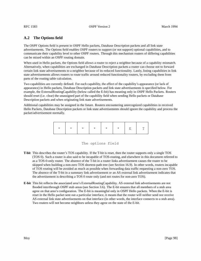
RFC 1583 OSPF Version 2 March 1994
A.2 The Options field
The OSPF Options field is present in OSPF Hello packets, Database Description packets and all link stateadvertisements. The Options field enables OSPF routers to support (or not support) optional capabilities, and tocommunicate their capability level to other OSPF routers. Through this mechanism routers of differing capabilitiescan be mixed within an OSPF routing domain.
When used in Hello packets, the Options field allows a router to reject a neighbor because of a capability mismatch.Alternatively, when capabilities are exchanged in Database Description packets a router can choose not to forwardcertain link state advertisements to a neighbor because of its reduced functionality. Lastly, listing capabilities in linkstate advertisements allows routers to route traffic around reduced functionality routers, by excluding them fromparts of the routing table calculation.
Two capabilities are currently defined. For each capability, the effect of the capability’s appearance (or lack ofappearance) in Hello packets, Database Description packets and link state advertisements is specified below. Forexample, the ExternalRoutingCapability (below called the E-bit) has meaning only in OSPF Hello Packets. Routersshould reset (i.e. clear) the unassigned part of the capability field when sending Hello packets or DatabaseDescription packets and when originating link state advertisements.
Additional capabilities may be assigned in the future. Routers encountering unrecognized capabilities in receivedHello Packets, Database Description packets or link state advertisements should ignore the capability and process thepacket/advertisement normally.
* * * * * * E T
The options field
T-bit This describes the router’s TOS capability. If the T-bit is reset, then the router supports only a single TOS(TOS 0). Such a router is also said to be incapable of TOS-routing, and elsewhere in this document referred toas a TOS-0-only router. The absence of the T-bit in a router links advertisement causes the router to beskipped when building a non-zero TOS shortest-path tree (see Section 16.9). In other words, routers incapableof TOS routing will be avoided as much as possible when forwarding data traffic requesting a non-zero TOS.The absence of the T-bit in a summary link advertisement or an AS external link advertisement indicates thatthe advertisement is describing a TOS 0 route only (and not routes for non-zero TOS).
E-bit This bit reflects the associated area’s ExternalRoutingCapability. AS external link advertisements are notflooded into/through OSPF stub areas (see Section 3.6). The E-bit ensures that all members of a stub areaagree on that area’s configuration. The E-bit is meaningful only in OSPF Hello packets. When the E-bit isreset in the Hello packet sent out a particular interface, it means that the router will neither send nor receiveAS external link state advertisements on that interface (in other words, the interface connects to a stub area).Two routers will not become neighbors unless they agree on the state of the E-bit.
Moy [Page 98]
RFC 1583 OSPF Version 2 March 1994
A.3 OSPF Packet Formats
There are five distinct OSPF packet types. All OSPF packet types begin with a standard 24 byte header. This headeris described first. Each packet type is then described in a succeeding section. In these sections each packet’s divisioninto fields is displayed, and then the field definitions are enumerated.
All OSPF packet types (other than the OSPF Hello packets) deal with lists of link state advertisements. For example,Link State Update packets implement the flooding of advertisements throughout the OSPF routing domain. Becauseof this, OSPF protocol packets cannot be parsed unless the format of link state advertisements is also understood.The format of Link state advertisements is described in Section A.4.
The receive processing of OSPF packets is detailed in Section 8.2. The sending of OSPF packets is explained inSection 8.1.
Moy [Page 99]
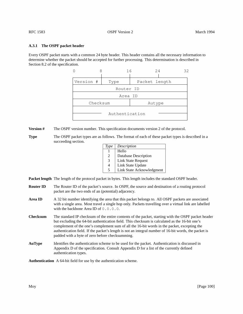
RFC 1583 OSPF Version 2 March 1994
A.3.1 The OSPF packet header
Every OSPF packet starts with a common 24 byte header. This header contains all the necessary information todetermine whether the packet should be accepted for further processing. This determination is described inSection 8.2 of the specification.
Authentication
AutypeChecksum
Area ID
Router ID
Packet lengthTypeVersion #
32241680
Version # The OSPF version number. This specification documents version 2 of the protocol.
Type The OSPF packet types are as follows. The format of each of these packet types is described in asucceeding section.
Type Description1 Hello2 Database Description3 Link State Request4 Link State Update5 Link State Acknowledgment
Packet length The length of the protocol packet in bytes. This length includes the standard OSPF header.
Router ID The Router ID of the packet’s source. In OSPF, the source and destination of a routing protocolpacket are the two ends of an (potential) adjacency.
Area ID A 32 bit number identifying the area that this packet belongs to. All OSPF packets are associatedwith a single area. Most travel a single hop only. Packets travelling over a virtual link are labelledwith the backbone Area ID of0.0.0.0 .
Checksum The standard IP checksum of the entire contents of the packet, starting with the OSPF packet headerbut excluding the 64-bit authentication field. This checksum is calculated as the 16-bit one’scomplement of the one’s complement sum of all the 16-bit words in the packet, excepting theauthentication field. If the packet’s length is not an integral number of 16-bit words, the packet ispadded with a byte of zero before checksumming.
AuType Identifies the authentication scheme to be used for the packet. Authentication is discussed inAppendix D of the specification. Consult Appendix D for a list of the currently definedauthentication types.
Authentication A 64-bit field for use by the authentication scheme.
Moy [Page 100]
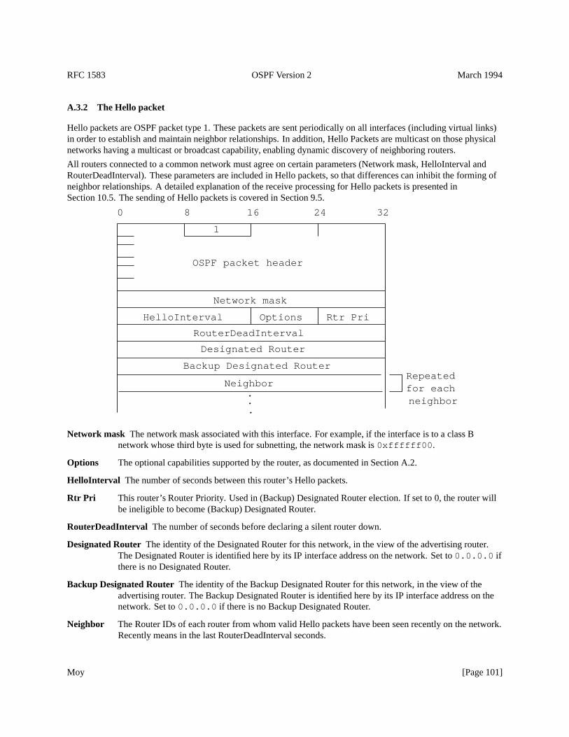
RFC 1583 OSPF Version 2 March 1994
A.3.2 The Hello packet
Hello packets are OSPF packet type 1. These packets are sent periodically on all interfaces (including virtual links)in order to establish and maintain neighbor relationships. In addition, Hello Packets are multicast on those physicalnetworks having a multicast or broadcast capability, enabling dynamic discovery of neighboring routers.
All routers connected to a common network must agree on certain parameters (Network mask, HelloInterval andRouterDeadInterval). These parameters are included in Hello packets, so that differences can inhibit the forming ofneighbor relationships. A detailed explanation of the receive processing for Hello packets is presented inSection 10.5. The sending of Hello packets is covered in Section 9.5.
Options
1
neighbor
Neighbor
Backup Designated Router
Designated Router
Rtr PriHelloInterval
RouterDeadInterval
Network mask
.
.
. for eachRepeated
32241680
OSPF packet header
Network mask The network mask associated with this interface. For example, if the interface is to a class Bnetwork whose third byte is used for subnetting, the network mask is0xffffff00 .
Options The optional capabilities supported by the router, as documented in Section A.2.
HelloInterval The number of seconds between this router’s Hello packets.
Rtr Pri This router’s Router Priority. Used in (Backup) Designated Router election. If set to 0, the router willbe ineligible to become (Backup) Designated Router.
RouterDeadInterval The number of seconds before declaring a silent router down.
Designated Router The identity of the Designated Router for this network, in the view of the advertising router.The Designated Router is identified here by its IP interface address on the network. Set to0.0.0.0 ifthere is no Designated Router.
Backup Designated RouterThe identity of the Backup Designated Router for this network, in the view of theadvertising router. The Backup Designated Router is identified here by its IP interface address on thenetwork. Set to0.0.0.0 if there is no Backup Designated Router.
Neighbor The Router IDs of each router from whom valid Hello packets have been seen recently on the network.Recently means in the last RouterDeadInterval seconds.
Moy [Page 101]
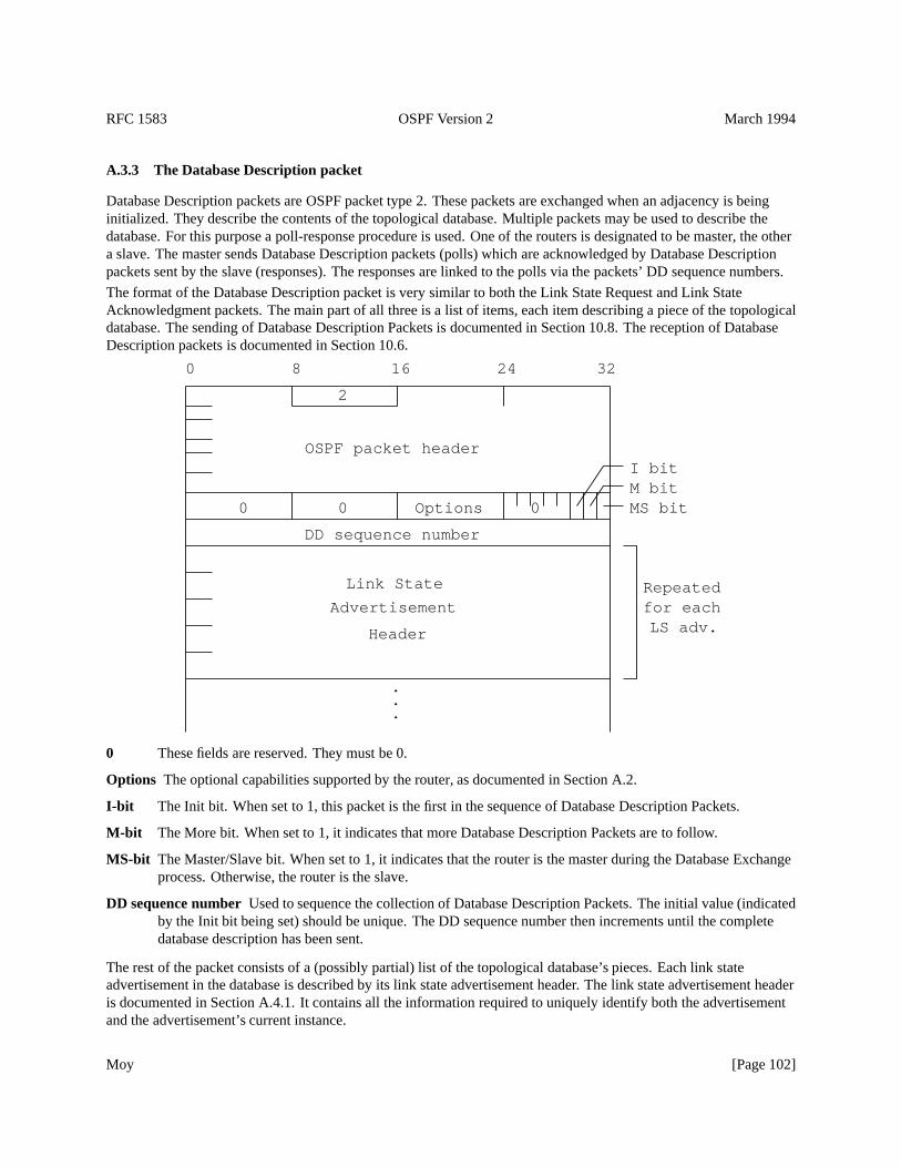
RFC 1583 OSPF Version 2 March 1994
A.3.3 The Database Description packet
Database Description packets are OSPF packet type 2. These packets are exchanged when an adjacency is beinginitialized. They describe the contents of the topological database. Multiple packets may be used to describe thedatabase. For this purpose a poll-response procedure is used. One of the routers is designated to be master, the othera slave. The master sends Database Description packets (polls) which are acknowledged by Database Descriptionpackets sent by the slave (responses). The responses are linked to the polls via the packets’ DD sequence numbers.
The format of the Database Description packet is very similar to both the Link State Request and Link StateAcknowledgment packets. The main part of all three is a list of items, each item describing a piece of the topologicaldatabase. The sending of Database Description Packets is documented in Section 10.8. The reception of DatabaseDescription packets is documented in Section 10.6.
Header
Advertisement
Link State
Options
2
DD sequence number
.
.
.
LS adv.
MS bitM bitI bit
000
for eachRepeated
32241680
OSPF packet header
0 These fields are reserved. They must be 0.
Options The optional capabilities supported by the router, as documented in Section A.2.
I-bit The Init bit. When set to 1, this packet is the first in the sequence of Database Description Packets.
M-bit The More bit. When set to 1, it indicates that more Database Description Packets are to follow.
MS-bit The Master/Slave bit. When set to 1, it indicates that the router is the master during the Database Exchangeprocess. Otherwise, the router is the slave.
DD sequence numberUsed to sequence the collection of Database Description Packets. The initial value (indicatedby the Init bit being set) should be unique. The DD sequence number then increments until the completedatabase description has been sent.
The rest of the packet consists of a (possibly partial) list of the topological database’s pieces. Each link stateadvertisement in the database is described by its link state advertisement header. The link state advertisement headeris documented in Section A.4.1. It contains all the information required to uniquely identify both the advertisementand the advertisement’s current instance.
Moy [Page 102]
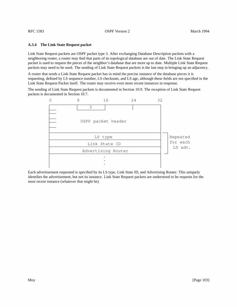
RFC 1583 OSPF Version 2 March 1994
A.3.4 The Link State Request packet
Link State Request packets are OSPF packet type 3. After exchanging Database Description packets with aneighboring router, a router may find that parts of its topological database are out of date. The Link State Requestpacket is used to request the pieces of the neighbor’s database that are more up to date. Multiple Link State Requestpackets may need to be used. The sending of Link State Request packets is the last step in bringing up an adjacency.
A router that sends a Link State Request packet has in mind the precise instance of the database pieces it isrequesting, defined by LS sequence number, LS checksum, and LS age, although these fields are not specified in theLink State Request Packet itself. The router may receive even more recent instances in response.
The sending of Link State Request packets is documented in Section 10.9. The reception of Link State Requestpackets is documented in Section 10.7.
3
.
.
.
LS adv.for eachRepeated
32241680
Advertising Router
Link State ID
LS type
OSPF packet header
Each advertisement requested is specified by its LS type, Link State ID, and Advertising Router. This uniquelyidentifies the advertisement, but not its instance. Link State Request packets are understood to be requests for themost recent instance (whatever that might be).
Moy [Page 103]
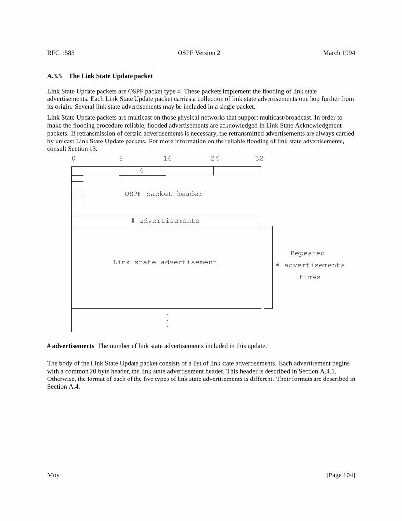
RFC 1583 OSPF Version 2 March 1994
A.3.5 The Link State Update packet
Link State Update packets are OSPF packet type 4. These packets implement the flooding of link stateadvertisements. Each Link State Update packet carries a collection of link state advertisements one hop further fromits origin. Several link state advertisements may be included in a single packet.
Link State Update packets are multicast on those physical networks that support multicast/broadcast. In order tomake the flooding procedure reliable, flooded advertisements are acknowledged in Link State Acknowledgmentpackets. If retransmission of certain advertisements is necessary, the retransmitted advertisements are always carriedby unicast Link State Update packets. For more information on the reliable flooding of link state advertisements,consult Section 13.
times
# advertisements
OSPF packet header
0 8 16 24 32
Repeated
# advertisements
Link state advertisement
.
.
.
4
# advertisementsThe number of link state advertisements included in this update.
The body of the Link State Update packet consists of a list of link state advertisements. Each advertisement beginswith a common 20 byte header, the link state advertisement header. This header is described in Section A.4.1.Otherwise, the format of each of the five types of link state advertisements is different. Their formats are described inSection A.4.
Moy [Page 104]
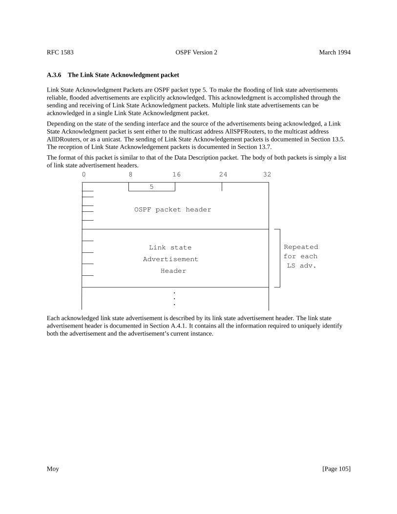
RFC 1583 OSPF Version 2 March 1994
A.3.6 The Link State Acknowledgment packet
Link State Acknowledgment Packets are OSPF packet type 5. To make the flooding of link state advertisementsreliable, flooded advertisements are explicitly acknowledged. This acknowledgment is accomplished through thesending and receiving of Link State Acknowledgment packets. Multiple link state advertisements can beacknowledged in a single Link State Acknowledgment packet.
Depending on the state of the sending interface and the source of the advertisements being acknowledged, a LinkState Acknowledgment packet is sent either to the multicast address AllSPFRouters, to the multicast addressAllDRouters, or as a unicast. The sending of Link State Acknowledgement packets is documented in Section 13.5.The reception of Link State Acknowledgement packets is documented in Section 13.7.
The format of this packet is similar to that of the Data Description packet. The body of both packets is simply a listof link state advertisement headers.
Header
Advertisement
Link state
5
.
.
.
LS adv.for eachRepeated
32241680
OSPF packet header
Each acknowledged link state advertisement is described by its link state advertisement header. The link stateadvertisement header is documented in Section A.4.1. It contains all the information required to uniquely identifyboth the advertisement and the advertisement’s current instance.
Moy [Page 105]
RFC 1583 OSPF Version 2 March 1994
A.4 Link state advertisement formats
There are five distinct types of link state advertisements. Each link state advertisement begins with a standard20-byte link state advertisement header. This header is explained in Section A.4.1. Succeeding sections then diagramthe separate link state advertisement types.
Each link state advertisement describes a piece of the OSPF routing domain. Every router originates a router linksadvertisement. In addition, whenever the router is elected Designated Router, it originates a network linksadvertisement. Other types of link state advertisements may also be originated (see Section 12.4). All link stateadvertisements are then flooded throughout the OSPF routing domain. The flooding algorithm is reliable, ensuringthat all routers have the same collection of link state advertisements. (See Section 13 for more informationconcerning the flooding algorithm). This collection of advertisements is called the link state (or topological) database.
From the link state database, each router constructs a shortest path tree with itself as root. This yields a routing table(see Section 11). For the details of the routing table build process, see Section 16.
Moy [Page 106]
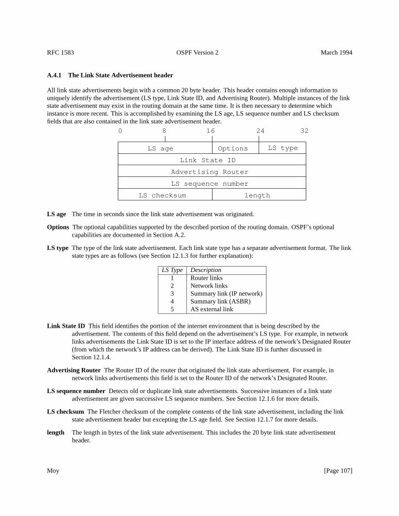
RFC 1583 OSPF Version 2 March 1994
A.4.1 The Link State Advertisement header
All link state advertisements begin with a common 20 byte header. This header contains enough information touniquely identify the advertisement (LS type, Link State ID, and Advertising Router). Multiple instances of the linkstate advertisement may exist in the routing domain at the same time. It is then necessary to determine whichinstance is more recent. This is accomplished by examining the LS age, LS sequence number and LS checksumfields that are also contained in the link state advertisement header.
Options
lengthLS checksum
LS sequence number
Advertising Router
Link State ID
LS typeLS age
32241680
LS age The time in seconds since the link state advertisement was originated.
Options The optional capabilities supported by the described portion of the routing domain. OSPF’s optionalcapabilities are documented in Section A.2.
LS type The type of the link state advertisement. Each link state type has a separate advertisement format. The linkstate types are as follows (see Section 12.1.3 for further explanation):
LS Type Description1 Router links2 Network links3 Summary link (IP network)4 Summary link (ASBR)5 AS external link
Link State ID This field identifies the portion of the internet environment that is being described by theadvertisement. The contents of this field depend on the advertisement’s LS type. For example, in networklinks advertisements the Link State ID is set to the IP interface address of the network’s Designated Router(from which the network’s IP address can be derived). The Link State ID is further discussed inSection 12.1.4.
Advertising Router The Router ID of the router that originated the link state advertisement. For example, innetwork links advertisements this field is set to the Router ID of the network’s Designated Router.
LS sequence numberDetects old or duplicate link state advertisements. Successive instances of a link stateadvertisement are given successive LS sequence numbers. See Section 12.1.6 for more details.
LS checksum The Fletcher checksum of the complete contents of the link state advertisement, including the linkstate advertisement header but excepting the LS age field. See Section 12.1.7 for more details.
length The length in bytes of the link state advertisement. This includes the 20 byte link state advertisementheader.
Moy [Page 107]
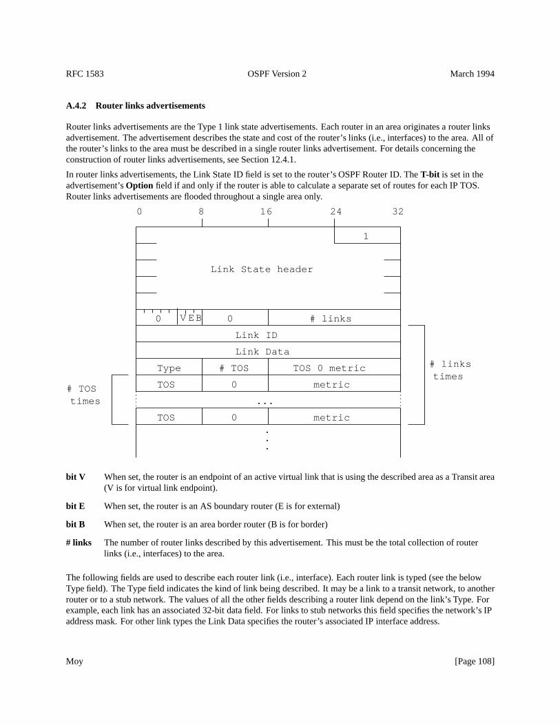
RFC 1583 OSPF Version 2 March 1994
A.4.2 Router links advertisements
Router links advertisements are the Type 1 link state advertisements. Each router in an area originates a router linksadvertisement. The advertisement describes the state and cost of the router’s links (i.e., interfaces) to the area. All ofthe router’s links to the area must be described in a single router links advertisement. For details concerning theconstruction of router links advertisements, see Section 12.4.1.
In router links advertisements, the Link State ID field is set to the router’s OSPF Router ID. TheT-bit is set in theadvertisement’sOption field if and only if the router is able to calculate a separate set of routes for each IP TOS.Router links advertisements are flooded throughout a single area only.
V BE0
.
.
.
times# links
...times# TOS
metric0TOS
0 # links
metric0TOS
TOS 0 metric# TOSType
Link Data
Link ID
Link State header
1
32241680
bit V When set, the router is an endpoint of an active virtual link that is using the described area as a Transit area(V is for virtual link endpoint).
bit E When set, the router is an AS boundary router (E is for external)
bit B When set, the router is an area border router (B is for border)
# links The number of router links described by this advertisement. This must be the total collection of routerlinks (i.e., interfaces) to the area.
The following fields are used to describe each router link (i.e., interface). Each router link is typed (see the belowType field). The Type field indicates the kind of link being described. It may be a link to a transit network, to anotherrouter or to a stub network. The values of all the other fields describing a router link depend on the link’s Type. Forexample, each link has an associated 32-bit data field. For links to stub networks this field specifies the network’s IPaddress mask. For other link types the Link Data specifies the router’s associated IP interface address.
Moy [Page 108]
RFC 1583 OSPF Version 2 March 1994
Type A quick description of the router link. One of the following. Note that host routes are classified as links tostub networks whose network mask is0xffffffff .
Type Description1 Point-to-point connection to another router2 Connection to a transit network3 Connection to a stub network4 Virtual link
Link ID Identifies the object that this router link connects to. Value depends on the link’s Type. When connectingto an object that also originates a link state advertisement (i.e., another router or a transit network) the LinkID is equal to the neighboring advertisement’s Link State ID. This provides the key for looking up saidadvertisement in the link state database. See Section 12.2 for more details.
Type Link ID1 Neighboring router’s Router ID2 IP address of Designated Router3 IP network/subnet number4 Neighboring router’s Router ID
Link Data Contents again depend on the link’s Type field. For connections to stub networks, it specifies thenetwork’s IP address mask. For unnumbered point-to-point connections, it specifies the interface’s MIB-II[RFC 1213] ifIndex value. For the other link types it specifies the router’s associated IP interface address.This latter piece of information is needed during the routing table build process, when calculating the IPaddress of the next hop. See Section 16.1.1 for more details.
# TOS The number of different TOS metrics given for this link, not counting the required metric for TOS 0. Forexample, if no additional TOS metrics are given, this field should be set to 0.
TOS 0 metric The cost of using this router link for TOS 0.
For each link, separate metrics may be specified for each Type of Service (TOS). The metric for TOS 0 must alwaysbe included, and was discussed above. Metrics for non-zero TOS are described below. The encoding of TOS inOSPF link state advertisements is described in Section 12.3. Note that the cost for non-zero TOS values that are notspecified defaults to the TOS 0 cost. Metrics must be listed in order of increasing TOS encoding. For example, themetric for TOS 16 must always follow the metric for TOS 8 when both are specified.
TOS IP Type of Service that this metric refers to. The encoding of TOS in OSPF link state advertisements isdescribed in Section 12.3.
metric The cost of using this outbound router link, for traffic of the specified TOS.
Moy [Page 109]
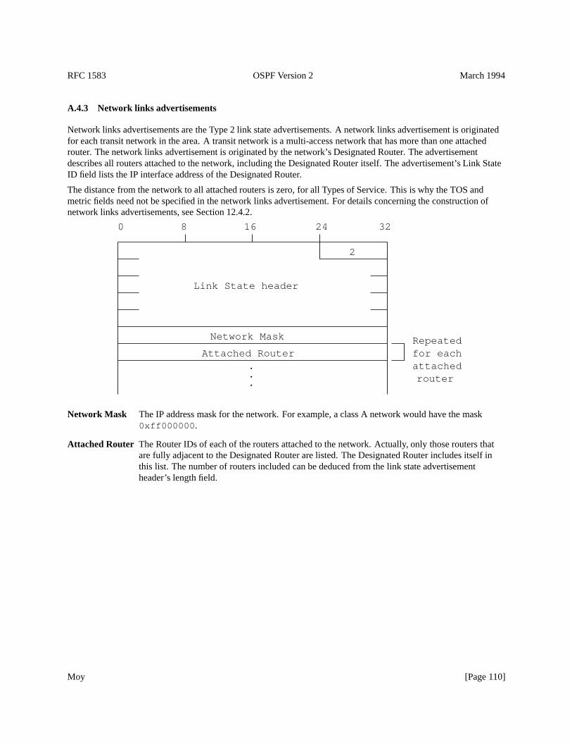
RFC 1583 OSPF Version 2 March 1994
A.4.3 Network links advertisements
Network links advertisements are the Type 2 link state advertisements. A network links advertisement is originatedfor each transit network in the area. A transit network is a multi-access network that has more than one attachedrouter. The network links advertisement is originated by the network’s Designated Router. The advertisementdescribes all routers attached to the network, including the Designated Router itself. The advertisement’s Link StateID field lists the IP interface address of the Designated Router.
The distance from the network to all attached routers is zero, for all Types of Service. This is why the TOS andmetric fields need not be specified in the network links advertisement. For details concerning the construction ofnetwork links advertisements, see Section 12.4.2.
.
.
.
Network Mask
routerattachedfor eachRepeated
Attached Router
2
Link State header
32241680
Network Mask The IP address mask for the network. For example, a class A network would have the mask0xff000000 .
Attached Router The Router IDs of each of the routers attached to the network. Actually, only those routers thatare fully adjacent to the Designated Router are listed. The Designated Router includes itself inthis list. The number of routers included can be deduced from the link state advertisementheader’s length field.
Moy [Page 110]
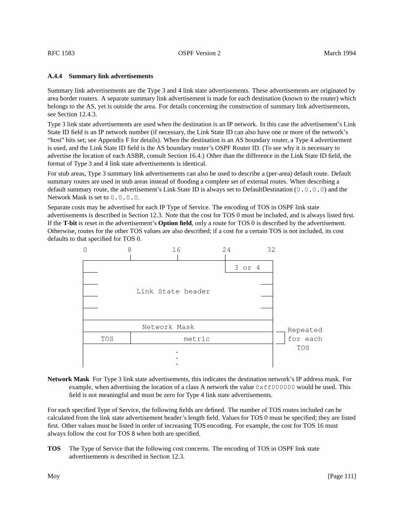
RFC 1583 OSPF Version 2 March 1994
A.4.4 Summary link advertisements
Summary link advertisements are the Type 3 and 4 link state advertisements. These advertisements are originated byarea border routers. A separate summary link advertisement is made for each destination (known to the router) whichbelongs to the AS, yet is outside the area. For details concerning the construction of summary link advertisements,see Section 12.4.3.
Type 3 link state advertisements are used when the destination is an IP network. In this case the advertisement’s LinkState ID field is an IP network number (if necessary, the Link State ID can also have one or more of the network’s“host” bits set; see Appendix F for details). When the destination is an AS boundary router, a Type 4 advertisementis used, and the Link State ID field is the AS boundary router’s OSPF Router ID. (To see why it is necessary toadvertise the location of each ASBR, consult Section 16.4.) Other than the difference in the Link State ID field, theformat of Type 3 and 4 link state advertisements is identical.
For stub areas, Type 3 summary link advertisements can also be used to describe a (per-area) default route. Defaultsummary routes are used in stub areas instead of flooding a complete set of external routes. When describing adefault summary route, the advertisement’s Link State ID is always set to DefaultDestination (0.0.0.0 ) and theNetwork Mask is set to0.0.0.0 .
Separate costs may be advertised for each IP Type of Service. The encoding of TOS in OSPF link stateadvertisements is described in Section 12.3. Note that the cost for TOS 0 must be included, and is always listed first.If the T-bit is reset in the advertisement’sOption field, only a route for TOS 0 is described by the advertisement.Otherwise, routes for the other TOS values are also described; if a cost for a certain TOS is not included, its costdefaults to that specified for TOS 0.
3 or 4
Network Mask
metricTOS
TOS for eachRepeated
.
.
.
Link State header
32241680
Network Mask For Type 3 link state advertisements, this indicates the destination network’s IP address mask. Forexample, when advertising the location of a class A network the value0xff000000 would be used. Thisfield is not meaningful and must be zero for Type 4 link state advertisements.
For each specified Type of Service, the following fields are defined. The number of TOS routes included can becalculated from the link state advertisement header’s length field. Values for TOS 0 must be specified; they are listedfirst. Other values must be listed in order of increasing TOS encoding. For example, the cost for TOS 16 mustalways follow the cost for TOS 8 when both are specified.
TOS The Type of Service that the following cost concerns. The encoding of TOS in OSPF link stateadvertisements is described in Section 12.3.
Moy [Page 111]

RFC 1583 OSPF Version 2 March 1994
metric The cost of this route. Expressed in the same units as the interface costs in the router links advertisements.
Moy [Page 112]
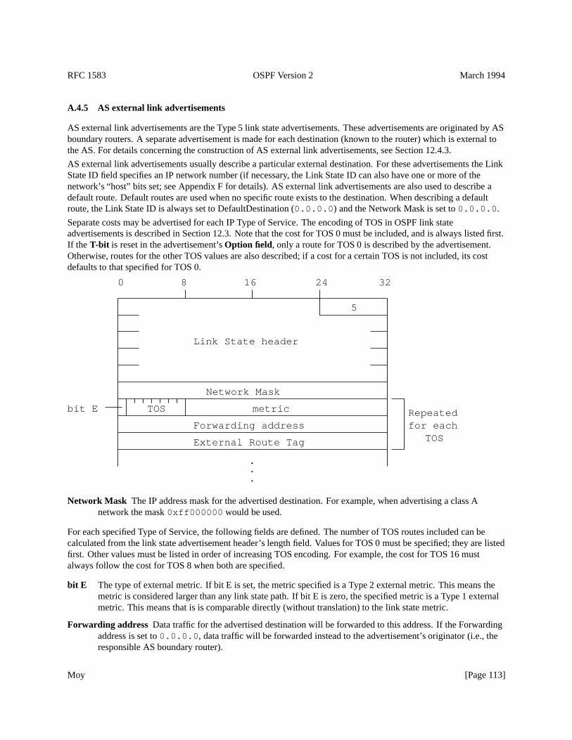
RFC 1583 OSPF Version 2 March 1994
A.4.5 AS external link advertisements
AS external link advertisements are the Type 5 link state advertisements. These advertisements are originated by ASboundary routers. A separate advertisement is made for each destination (known to the router) which is external tothe AS. For details concerning the construction of AS external link advertisements, see Section 12.4.3.
AS external link advertisements usually describe a particular external destination. For these advertisements the LinkState ID field specifies an IP network number (if necessary, the Link State ID can also have one or more of thenetwork’s “host” bits set; see Appendix F for details). AS external link advertisements are also used to describe adefault route. Default routes are used when no specific route exists to the destination. When describing a defaultroute, the Link State ID is always set to DefaultDestination (0.0.0.0 ) and the Network Mask is set to0.0.0.0 .
Separate costs may be advertised for each IP Type of Service. The encoding of TOS in OSPF link stateadvertisements is described in Section 12.3. Note that the cost for TOS 0 must be included, and is always listed first.If the T-bit is reset in the advertisement’sOption field, only a route for TOS 0 is described by the advertisement.Otherwise, routes for the other TOS values are also described; if a cost for a certain TOS is not included, its costdefaults to that specified for TOS 0.
5
Forwarding address
External Route Tag
Network Mask
.
.
.
bit E metric
TOS
TOS
for eachRepeated
Link State header
32241680
Network Mask The IP address mask for the advertised destination. For example, when advertising a class Anetwork the mask0xff000000 would be used.
For each specified Type of Service, the following fields are defined. The number of TOS routes included can becalculated from the link state advertisement header’s length field. Values for TOS 0 must be specified; they are listedfirst. Other values must be listed in order of increasing TOS encoding. For example, the cost for TOS 16 mustalways follow the cost for TOS 8 when both are specified.
bit E The type of external metric. If bit E is set, the metric specified is a Type 2 external metric. This means themetric is considered larger than any link state path. If bit E is zero, the specified metric is a Type 1 externalmetric. This means that is is comparable directly (without translation) to the link state metric.
Forwarding address Data traffic for the advertised destination will be forwarded to this address. If the Forwardingaddress is set to0.0.0.0 , data traffic will be forwarded instead to the advertisement’s originator (i.e., theresponsible AS boundary router).
Moy [Page 113]
RFC 1583 OSPF Version 2 March 1994
TOS The Type of Service that the following cost concerns. The encoding of TOS in OSPF link stateadvertisements is described in Section 12.3.
metric The cost of this route. Interpretation depends on the external type indication (bit E above).
External Route Tag A 32-bit field attached to each external route. This is not used by the OSPF protocol itself. Itmay be used to communicate information between AS boundary routers; the precise nature of suchinformation is outside the scope of this specification.
Moy [Page 114]
RFC 1583 OSPF Version 2 March 1994
B Architectural Constants
Several OSPF protocol parameters have fixed architectural values. These parameters have been referred to in the textby names such as LSRefreshTime. The same naming convention is used for the configurable protocol parameters.They are defined in Appendix C.
The name of each architectural constant follows, together with its value and a short description of its function.
LSRefreshTime The maximum time between distinct originations of any particular link state advertisement. Whenthe LS age field of one of the router’s self-originated advertisements reaches the value LSRefreshTime, a newinstance of the link state advertisement is originated, even though the contents of the advertisement (apart fromthe link state header) will be the same. The value of LSRefreshTime is set to 30 minutes.
MinLSInterval The minimum time between distinct originations of any particular link state advertisement. Thevalue of MinLSInterval is set to 5 seconds.
MaxAge The maximum age that a link state advertisement can attain. When an advertisement’s LS age field reachesMaxAge, it is reflooded in an attempt to flush the advertisement from the routing domain (See Section 14).Advertisements of age MaxAge are not used in the routing table calculation. The value of MaxAge must begreater than LSRefreshTime. The value of MaxAge is set to 1 hour.
CheckAge When the age of a link state advertisement (that is contained in the link state database) hits a multiple ofCheckAge, the advertisement’s checksum is verified. An incorrect checksum at this time indicates a seriouserror. The value of CheckAge is set to 5 minutes.
MaxAgeDiff The maximum time dispersion that can occur, as a link state advertisement is flooded throughout theAS. Most of this time is accounted for by the link state advertisements sitting on router output queues (andtherefore not aging) during the flooding process. The value of MaxAgeDiff is set to 15 minutes.
LSInfinity The metric value indicating that the destination described by a link state advertisement is unreachable.Used in summary link advertisements and AS external link advertisements as an alternative to premature aging(see Section 14.1). It is defined to be the 24-bit binary value of all ones:0xffffff .
DefaultDestination The Destination ID that indicates the default route. This route is used when no other matchingrouting table entry can be found. The default destination can only be advertised in AS external linkadvertisements and in stub areas’ type 3 summary link advertisements. Its value is the IP address0.0.0.0 .
Moy [Page 115]
RFC 1583 OSPF Version 2 March 1994
C Configurable Constants
The OSPF protocol has quite a few configurable parameters. These parameters are listed below. They are groupedinto general functional categories (area parameters, interface parameters, etc.). Sample values are given for some ofthe parameters.
Some parameter settings need to be consistent among groups of routers. For example, all routers in an area mustagree on that area’s parameters, and all routers attached to a network must agree on that network’s IP networknumber and mask.
Some parameters may be determined by router algorithms outside of this specification (e.g., the address of a hostconnected to the router via a SLIP line). From OSPF’s point of view, these items are still configurable.
C.1 Global parameters
In general, a separate copy of the OSPF protocol is run for each area. Because of this, most configuration parametersare defined on a per-area basis. The few global configuration parameters are listed below.
Router ID This is a 32-bit number that uniquely identifies the router in the Autonomous System. One algorithm forRouter ID assignment is to choose the largest or smallest IP address assigned to the router. If a router’s OSPFRouter ID is changed, the router’s OSPF software should be restarted before the new Router ID takes effect.Before restarting in order to change its Router ID, the router should flush its self-originated link stateadvertisements from the routing domain (see Section 14.1), or they will persist for up to MaxAge minutes.
TOS capability This item indicates whether the router will calculate separate routes based on TOS. For moreinformation, see Sections 4.5 and 16.9.
C.2 Area parameters
All routers belonging to an area must agree on that area’s configuration. Disagreements between two routers willlead to an inability for adjacencies to form between them, with a resulting hindrance to the flow of routing protocoland data traffic. The following items must be configured for an area:
Area ID This is a 32-bit number that identifies the area. The Area ID of0.0.0.0 is reserved for the backbone. Ifthe area represents a subnetted network, the IP network number of the subnetted network may be used for theArea ID.
List of address rangesAn OSPF area is defined as a list of address ranges. Each address range consists of thefollowing items:
[IP address, mask] Describes the collection of IP addresses contained in the address range. Networks andhosts are assigned to an area depending on whether their addresses fall into one of the area’s definingaddress ranges. Routers are viewed as belonging to multiple areas, depending on their attached networks’area membership.
Status Set to either Advertise or DoNotAdvertise. Routing information is condensed at area boundaries.External to the area, at most a single route is advertised (via a summary link advertisement) for eachaddress range. The route is advertised if and only if the address range’s Status is set to Advertise.Unadvertised ranges allow the existence of certain networks to be intentionally hidden from other areas.Status is set to Advertise by default.
Moy [Page 116]
RFC 1583 OSPF Version 2 March 1994
As an example, suppose an IP subnetted network is to be its own OSPF area. The area would be configured asa single address range, whose IP address is the address of the subnetted network, and whose mask is the naturalclass A, B, or C address mask. A single route would be advertised external to the area, describing the entiresubnetted network.
AuType Each area can be configured for a separate type of authentication. See Appendix D for a discussion of thedefined authentication types.
ExternalRoutingCapability Whether AS external advertisements will be flooded into/throughout the area. If ASexternal advertisements are excluded from the area, the area is called a “stub”. Internal to stub areas, routing toexternal destinations will be based solely on a default summary route. The backbone cannot be configured as astub area. Also, virtual links cannot be configured through stub areas. For more information, see Section 3.6.
StubDefaultCost If the area has been configured as a stub area, and the router itself is an area border router, then theStubDefaultCost indicates the cost of the default summary link that the router should advertise into the area.There can be a separate cost configured for each IP TOS. See Section 12.4.3 for more information.
C.3 Router interface parameters
Some of the configurable router interface parameters (such as IP interface address and subnet mask) actually implyproperties of the attached networks, and therefore must be consistent across all the routers attached to that network.The parameters that must be configured for a router interface are:
IP interface address The IP protocol address for this interface. This uniquely identifies the router over the entireinternet. An IP address is not required on serial lines. Such a serial line is called “unnumbered”.
IP interface mask Also referred to as the subnet mask, this indicates the portion of the IP interface address thatidentifies the attached network. Masking the IP interface address with the IP interface mask yields the IPnetwork number of the attached network. On point-to-point networks and virtual links, the IP interface mask isnot defined. On these networks, the link itself is not assigned an IP network number, and so the addresses ofeach side of the link are assigned independently, if they are assigned at all.
Interface output cost(s) The cost of sending a packet on the interface, expressed in the link state metric. This isadvertised as the link cost for this interface in the router’s router links advertisement. There may be a separatecost for each IP Type of Service. The interface output cost(s) must always be greater than 0.
RxmtInterval The number of seconds between link state advertisement retransmissions, for adjacencies belongingto this interface. Also used when retransmitting Database Description and Link State Request Packets. Thisshould be well over the expected round-trip delay between any two routers on the attached network. Thesetting of this value should be conservative or needless retransmissions will result. It will need to be larger onlow speed serial lines and virtual links. Sample value for a local area network: 5 seconds.
InfTransDelay The estimated number of seconds it takes to transmit a Link State Update Packet over this interface.Link state advertisements contained in the update packet must have their age incremented by this amountbefore transmission. This value should take into account the transmission and propagation delays of theinterface. It must be greater than 0. Sample value for a local area network: 1 second.
Router Priority An 8-bit unsigned integer. When two routers attached to a network both attempt to becomeDesignated Router, the one with the highest Router Priority takes precedence. If there is still a tie, the routerwith the highest Router ID takes precedence. A router whose Router Priority is set to 0 is ineligible to becomeDesignated Router on the attached network. Router Priority is only configured for interfaces to multi-accessnetworks.
Moy [Page 117]
RFC 1583 OSPF Version 2 March 1994
HelloInterval The length of time, in seconds, between the Hello Packets that the router sends on the interface. Thisvalue is advertised in the router’s Hello Packets. It must be the same for all routers attached to a commonnetwork. The smaller the HelloInterval, the faster topological changes will be detected, but more OSPFrouting protocol traffic will ensue. Sample value for a X.25 PDN network: 30 seconds. Sample value for alocal area network: 10 seconds.
RouterDeadInterval After ceasing to hear a router’s Hello Packets, the number of seconds before its neighborsdeclare the router down. This is also advertised in the router’s Hello Packets in their RouterDeadInterval field.This should be some multiple of the HelloInterval (say 4). This value again must be the same for all routersattached to a common network.
Authentication key This configured data allows the authentication procedure to generate and/or verify theauthentication field in the OSPF header. This value again must be the same for all routers attached to acommon network. For example, if the AuType indicates simple password, the Authentication key would be a64-bit password. This key would be inserted directly into the OSPF header when originating routing protocolpackets. There could be a separate password for each network.
C.4 Virtual link parameters
Virtual links are used to restore/increase connectivity of the backbone. Virtual links may be configured between anypair of area border routers having interfaces to a common (non-backbone) area. The virtual link appears as anunnumbered point-to-point link in the graph for the backbone. The virtual link must be configured in both of the areaborder routers.
A virtual link appears in router links advertisements (for the backbone) as if it were a separate router interface to thebackbone. As such, it has all of the parameters associated with a router interface (see Section C.3). Although avirtual link acts like an unnumbered point-to-point link, it does have an associatedIP interface address. Thisaddress is used as the IP source in OSPF protocol packets it sends along the virtual link, and is set dynamicallyduring the routing table build process.Interface output cost is also set dynamically on virtual links to be the cost ofthe intra-area path between the two routers. The parameterRxmtInterval must be configured, and should be wellover the expected round-trip delay between the two routers. This may be hard to estimate for a virtual link; it is betterto err on the side of making it too large.Router Priority is not used on virtual links.
A virtual link is defined by the following two configurable parameters: the Router ID of the virtual link’s otherendpoint, and the (non-backbone) area through which the virtual link runs (referred to as the virtual link’sTransitarea). Virtual links cannot be configured through stub areas.
C.5 Non-broadcast, multi-access network parameters
OSPF treats a non-broadcast, multi-access network much like it treats a broadcast network. Since there may be manyrouters attached to the network, a Designated Router is selected for the network. This Designated Router thenoriginates a networks links advertisement, which lists all routers attached to the non-broadcast network.
However, due to the lack of broadcast capabilities, it is necessary to use configuration parameters in the DesignatedRouter selection. These parameters need only be configured in those routers that are themselves eligible to becomeDesignated Router (i.e., those router’s whose Router Priority for the network is non-zero):
List of all other attached routers The list of all other routers attached to the non-broadcast network. Each router islisted by its IP interface address on the network. Also, for each router listed, that router’s eligibility to becomeDesignated Router must be defined. When an interface to a non-broadcast network comes up, the router sendsHello Packets only to those neighbors eligible to become Designated Router, until the identity of theDesignated Router is discovered.
Moy [Page 118]
RFC 1583 OSPF Version 2 March 1994
PollInterval If a neighboring router has become inactive (Hello Packets have not been seen for RouterDeadIntervalseconds), it may still be necessary to send Hello Packets to the dead neighbor. These Hello Packets will be sentat the reduced rate PollInterval, which should be much larger than HelloInterval. Sample value for a PDNX.25 network: 2 minutes.
C.6 Host route parameters
Host routes are advertised in router links advertisements as stub networks with mask0xffffffff . They indicateeither router interfaces to point-to-point networks, looped router interfaces, or IP hosts that are directly connected tothe router (e.g., via a SLIP line). For each host directly connected to the router, the following items must beconfigured:
Host IP address The IP address of the host.
Cost of link to host The cost of sending a packet to the host, in terms of the link state metric. There may be multiplecosts configured, one for each IP TOS. However, since the host probably has only a single connection to theinternet, the actual configured cost(s) in many cases is unimportant (i.e., will have no effect on routing).
Moy [Page 119]
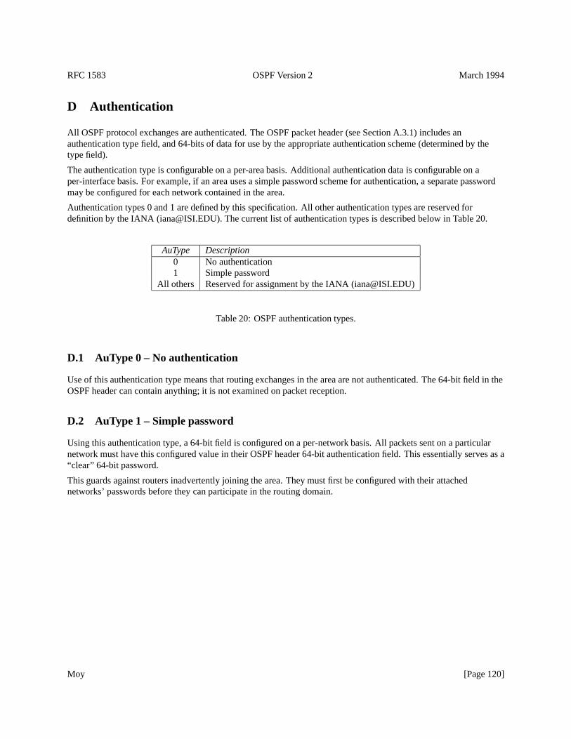
RFC 1583 OSPF Version 2 March 1994
D Authentication
All OSPF protocol exchanges are authenticated. The OSPF packet header (see Section A.3.1) includes anauthentication type field, and 64-bits of data for use by the appropriate authentication scheme (determined by thetype field).
The authentication type is configurable on a per-area basis. Additional authentication data is configurable on aper-interface basis. For example, if an area uses a simple password scheme for authentication, a separate passwordmay be configured for each network contained in the area.
Authentication types 0 and 1 are defined by this specification. All other authentication types are reserved fordefinition by the IANA ([email protected]). The current list of authentication types is described below in Table 20.
AuType Description0 No authentication1 Simple password
All others Reserved for assignment by the IANA ([email protected])
Table 20: OSPF authentication types.
D.1 AuType 0 – No authentication
Use of this authentication type means that routing exchanges in the area are not authenticated. The 64-bit field in theOSPF header can contain anything; it is not examined on packet reception.
D.2 AuType 1 – Simple password
Using this authentication type, a 64-bit field is configured on a per-network basis. All packets sent on a particularnetwork must have this configured value in their OSPF header 64-bit authentication field. This essentially serves as a“clear” 64-bit password.
This guards against routers inadvertently joining the area. They must first be configured with their attachednetworks’ passwords before they can participate in the routing domain.
Moy [Page 120]
RFC 1583 OSPF Version 2 March 1994
E Differences from RFC 1247
This section documents the differences between this memo and RFC 1247. These differences include a fix for aproblem involving OSPF virtual links, together with minor enhancements and clarifications to the protocol. Alldifferences are backward-compatible. Implementations of this memo and of RFC 1247 will interoperate.
E.1 A fix for a problem with OSPF Virtual links
In RFC 1247, certain configurations of OSPF virtual links can cause routing loops. The root of the problem is thatwhile there is an information mismatch at the boundary of any virtual link’s Transit area, a backbone path can stillcross the boundary. RFC 1247 attempted to compensate for this information mismatch by adjusting any backbonepath as it enters the transit area (see Section 16.3 in RFC 1247). However, this proved not to be enough. This memofixes the problem by having all area border routers determine, by looking at summary links, whether better backbonepaths can be found through the transit areas.
This fix simplifies the OSPF virtual link logic, and consists of the following components:
� A new bit has been defined in the router links advertisement, calledbit V . Bit V is set in a router’s router linksadvertisement for Area A if and only if the router is an endpoint of an active virtual link that uses Area A as itsTransit area (see Sections 12.4.1 and A.4.2). This enables the other routers attached to Area A to discoverwhether the area supports any virtual links (i.e., is a transit area). This discovery is done during the calculationof Area A’s shortest-path tree (see Section 16.1).
� To aid in the description of the algorithm, a new parameter has been added to the OSPF area structure:TransitCapability . This parameter indicates whether the area supports any active virtual links. Equivalently,it indicates whether the area can carry traffic that neither originates nor terminates in the area itself.
� The calculation in Section 16.3 of RFC 1247 has been replaced. The new calculation, performed by areaborder routers only, examines the summary links belonging to all attached transit areas to see whether thetransit areas can provide better paths than those already found in Sections 16.1 and 16.2.
� The incremental calculations in Section 16.5 have been updated as a result of the new calculations inSection 16.3.
E.2 Supporting supernetting and subnet 0
In RFC 1247, an OSPF router cannot originate separate AS external link advertisements (or separate summary linkadvertisements) for two networks that have the same address but different masks. This situation can arise whensubnet 0 of a network has been assigned (a practice that is generally discouraged), or when using supernetting asdescribed in [RFC 1519] (a practice that is generally encouraged to reduce the size of routing tables), or even whenin transition from one mask to another on a subnet. Using supernetting as an example, you might want to aggregatethe four class C networks192.9.4.0-192.9.7.0 , advertising one route for the aggregation and another for thesingle class C network192.9.4.0 .
The reason behind this limitation is that in RFC 1247, the Link State ID of AS external link advertisements andsummary link advertisements is set equal to the described network’s IP address. In the above example, RFC 1247would assign both advertisements the Link State ID of192.9.4.0 , making them in essence the sameadvertisement. This memo fixes the problem by relaxing the setting of the Link State ID so that any of the “host” bitsof the network address can also be set. This allows you to disambiguate advertisements for networks having thesame address but different masks. Given an AS external link advertisement (or a summary link advertisement), the
Moy [Page 121]
RFC 1583 OSPF Version 2 March 1994
described network’s address can now be obtained by masking the Link State ID with the network mask carried in thebody of the advertisement. Again using the above example, the aggregate can now be advertised using a Link StateID of 192.9.4.0 and the single class C network advertised simultaneously using the Link State ID of 192.9.4.255.
Appendix F gives one possible algorithm for setting one or more “host” bits in the Link State ID in order todisambiguate advertisements. It should be noted that this is a local decision. Each router in an OSPF system is free touse its own algorithm, since only those advertisements originated by the router itself are affected.
It is believed that this change will be more or less compatible with implementations of RFC 1247. Implementationsof RFC 1247 will probably either a) install routing table entries that won’t be used or b) do the correct processing asoutlined in this memo or c) mark the advertisement as unusable when presented with a Link State ID that has one ormore of the host bits set. However, in the interest of interoperability, implementations of this memo should only setthe host bits in Link State IDs when absolutely necessary.
The change affects Sections 12.1.4, 12.4.3, 12.4.5, 16.2, 16.3, 16.4, 16.5, 16.6, A.4.4 and A.4.5.
E.3 Obsoleting LSInfinity in router links advertisements
The metric of LSInfinity can no longer be used in router links advertisements to indicate unusable links. This isbeing done for several reasons:
� First, it removes any possible confusion in an OSPF area as to just which routers/networks are reachable in thearea. For example, the above virtual link fix relies on detecting the existence of virtual links when running theDijkstra. However, when one-directional links (i.e., cost of LSInfinity in one direction, but not the other) arepossible, some routers may detect the existence of virtual links while others may not. This may defeat the fixfor the virtual link problem.
� Second, it also helps OSPF’s Multicast routing extensions (MOSPF), because one-way reachability can lead toplaces that are reachable via unicast but not multicast, or vice versa.
The two prior justifications for using LSInfinity in router links advertisements were 1) it was a way to not supportTOS before TOS was optional and 2) it went along with strong TOS interpretations. These justifications are nolonger valid. However, LSInfinity will continue to mean ”unreachable” in summary link advertisements and ASexternal link advertisements, as some implementations use this as an alternative to the premature aging procedurespecified in Section 14.1.
This change has one other side effect. When two routers are connected via a virtual link whose underlying path isnon-TOS-capable, they must now revert to being non-TOS-capable routers themselves, instead of the previousbehavior of advertising the non-zero TOS costs of the virtual link as LSInfinity. See Section 15 for details.
E.4 TOS encoding updated
The encoding of TOS in OSPF link state advertisements has been updated to reflect the new TOS value (minimizemonetary cost) defined by [RFC 1349]. The OSPF encoding is defined in Section 12.3, which is identical in contentto Section A.5 of [RFC 1349].
E.5 Summarizing routes into transit areas
RFC 1247 mandated that routes associated with Area A are never summarized back into Area A. However, thismemo further reduces the number of summary links originated by refusing to summarize into Area A those routes
Moy [Page 122]
RFC 1583 OSPF Version 2 March 1994
having next hops belonging to Area A. This is an optimization over RFC 1247 behavior when virtual links arepresent. For example, in the area configuration of Figure 6, Router RT11 need only originate a single summary linkhaving the (collapsed) destination N9-N11,H1 into its connected transit area Area 2, since all of its other eligibleroutes have next hops belonging to Area 2 (and as such only need be advertised by other area border routers; in thiscase, Routers RT10 and RT7). This is the logical equivalent of a Distance Vector protocol’s split horizon logic.
This change appears in Section 12.4.3.
E.6 Summarizing routes into stub areas
RFC 1247 mandated that area border routers attached to stub areas must summarize all inter-area routes into the stubareas. However, while area border routers connected to OSPF stub areas must originate default summary links intothe stub area, they need not summarize other routes into the stub area. The amount of summarization done into stubareas can instead be put under configuration control. The network administrator can then make the trade-off betweenoptimal routing and database size.
This change appears in Sections 12.4.3 and 12.4.4.
E.7 Flushing anomalous network links advertisements
Text was added indicating that a network links advertisement whose Link State ID is equal to one of the router’s ownIP interface addresses should be considered to be self-originated, regardless of the setting of the advertisement’sAdvertising Router. If the Advertising Router of such an advertisement is not equal to the router’s own Router ID,the advertisement should be flushed from the routing domain using the premature aging procedure specified inSection 14.1. This case should be rare, and it indicates that the router’s Router ID has changed since originating theadvertisement.
Failure to flush these anomalous advertisements could lead to multiple network links advertisements having the sameLink State ID. This in turn could cause the Dijkstra calculation in Section 16.1 to fail, since it would be impossible totell which network links advertisement is valid (i.e., more recent).
This change appears in Sections 13.4 and 14.1.
E.8 Required Statistics appendix deleted
Appendix D of RFC 1247, which specified a list of required statistics for an OSPF implementation, has been deleted.That appendix has been superseded by the two documents: the OSPF Version 2 Management Information Base andthe OSPF Version 2 Traps.
E.9 Other changes
The following small changes were also made to RFC 1247:
� When representing unnumbered point-to-point networks in router links advertisements, the correspondingLink Data field should be set to the unnumbered interface’s MIB-II [RFC 1213] ifIndex value.
� A comment was added to Step 3 of the Dijkstra algorithm in Section 16.1. When removing vertices from thecandidate list, and when there is a choice of vertices closest to the root, network vertices must be chosen beforerouter vertices in order to necessarily find all equal-cost paths.
Moy [Page 123]
RFC 1583 OSPF Version 2 March 1994
� A comment was added to Section 12.4.3 noting that a summary link advertisement cannot express a reachabledestination whose path cost equals or exceeds LSInfinity.
� A comment was added to Section 15 noting that a virtual link whose underlying path has cost greater thanhexadecimal0xffff (the maximum size of an interface cost in a router links advertisement) should beconsidered inoperational.
� An option was added to the definition of area address ranges, allowing the network administrator to specifythat a particular range should not be advertised to other OSPF areas. This enables the existence of certainnetworks to be hidden from other areas. This change appears in Sections 12.4.3 and C.2.
� A note was added reminding implementors that bit E (the AS boundary router indication) should never be setin a router links advertisement for a stub area, since stub areas cannot contain AS boundary routers. Thischange appears in Section 12.4.1.
Moy [Page 124]
RFC 1583 OSPF Version 2 March 1994
F An algorithm for assigning Link State IDs
In RFC 1247, the Link State ID in AS external link advertisements and summary link advertisements is set to thedescribed network’s IP address. This memo relaxes that requirement, allowing one or more of the network’s host bitsto be set in the Link State ID. This allows the router to originate separate advertisements for networks having thesame addresses, yet different masks. Such networks can occur in the presence of supernetting and subnet 0s (seeSection E.2 for more information).
This appendix gives one possible algorithm for setting the host bits in Link State IDs. The choice of such analgorithm is a local decision. Separate routers are free to use different algorithms, since the only advertisementsaffected are the ones that the router itself originates. The only requirement on the algorithms used is that thenetwork’s IP address should be used as the Link State ID (the RFC 1247 behavior) whenever possible.
The algorithm below is stated for AS external link advertisements. This is only for clarity; the exact same algorithmcan be used for summary link advertisements. Suppose that the router wishes to originate an AS external linkadvertisement for a network having address NA and mask NM1. The following steps are then used to determine theadvertisement’s Link State ID:
1. Determine whether the router is already originating an AS external link advertisement with Link State ID equalto NA (in such an advertisement the router itself will be listed as the advertisement’s Advertising Router). Ifnot, set the Link State ID equal to NA (the RFC 1247 behavior) and the algorithm terminates. Otherwise,
2. Obtain the network mask from the body of the already existing AS external link advertisement. Call this maskNM2. There are then two cases:
� NM1 is longer (i.e., more specific) than NM2. In this case, set the Link State ID in the new advertisementto be the network [NA,NM1] with all the host bits set (i.e., equal to NA or’ed together with all the bitsthat are not set in NM1, which is network [NA,NM1]’s broadcast address).
� NM2 is longer than NM1. In this case, change the existing advertisement (having Link State ID of NA)to reference the new network [NA,NM1] by incrementing the sequence number, changing the mask in thebody to NM1 and using the cost for the new network. Then originate a new advertisement for the oldnetwork [NA,NM2], with Link State ID equal to NA or’ed together with the bits that are not set in NM2(i.e., network [NA,NM2]’s broadcast address).
The above algorithm assumes that all masks are contiguous; this ensures that when two networks have the sameaddress, one mask is more specific than the other. The algorithm also assumes that no network exists having anaddress equal to another network’s broadcast address. Given these two assumptions, the above algorithm alwaysproduces unique Link State IDs. The above algorithm can also be reworded as follows: When originating an ASexternal link state advertisement, try to use the network number as the Link State ID. If that produces a conflict,examine the two networks in conflict. One will be a subset of the other. For the less specific network, use thenetwork number as the Link State ID and for the more specific use the network’s broadcast address instead (i.e., flipall the ”host” bits to 1). If the most specific network was originated first, this will cause you to originate two linkstate advertisements at once.
As an example of the algorithm, consider its operation when the following sequence of events occurs in a singlerouter (Router A).
1. Router A wants to originate an AS external link advertisement for [10.0.0.0,255.255.255.0 ]:
(a) A Link State ID of10.0.0.0 is used.
2. Router A then wants to originate an AS external link advertisement for [10.0.0.0,255.255.0.0 ]:
Moy [Page 125]
RFC 1583 OSPF Version 2 March 1994
(a) The advertisement for [10.0.0,0,255.255.255.0 ] is reoriginated using a new Link State ID of10.0.0.255 .
(b) A Link State ID of10.0.0.0 is used for [10.0.0.0,255.255.0.0 ].
3. Router A then wants to originate an AS external link advertisement for [10.0.0.0,255.0.0.0 ]:
(a) The advertisement for [10.0.0.0,255.255.0.0 ] is reoriginated using a new Link State ID of10.0.255.255 .
(b) A Link State ID of10.0.0.0 is used for [10.0.0.0,255.0.0.0 ].
(c) The network [10.0.0.0,255.255.255.0 ] keeps its Link State ID of10.0.0.255 .
Moy [Page 126]
RFC 1583 OSPF Version 2 March 1994
Security Considerations
All OSPF protocol exchanges are authenticated. This is accomplished through authentication fields contained in theOSPF packet header. For more information, see Sections 8.1, 8.2, and Appendix D.
Author’s Address
John MoyProteon, Inc.9 Technology DriveWestborough, MA 01581
Phone: 508-898-2800Fax: 508-898-3176EMail: [email protected]
Moy [Page 127]


![RFC Editor Tutorial -- “How to Write an RFC”xml.coverpages.org/IETF-RFC-Tutorial63-2005.pdf · 31 Jul 05 RFC Editor 7 RFCs RFC document series Begun by Steve Crocker [RFC 3] and](https://img.pdfslide.us/doc/110x75/5f32dade5b09150ccd3dbc58/rfc-editor-tutorial-aoehow-to-write-an-rfcaxml-31-jul-05-rfc-editor-7-rfcs.jpg)


![CE Router Conformance Test Specification · [IPv6-SPEC] R. Hinden, S. Deering, Internet Protocol, Version 6 (IPv6) Specification, RFC 2460, December 1998. [RFC 2827] P. Ferguson,](https://img.pdfslide.us/doc/110x75/601a7e481480e4327e1a9b9e/ce-router-conformance-test-specification-ipv6-spec-r-hinden-s-deering-internet.jpg)


![RFC 5246 [the Transport Layer Security (TLS) Protocol Version 1.2]](https://img.pdfslide.us/doc/110x75/54f76f5e4a79593f188b4b63/rfc-5246-the-transport-layer-security-tls-protocol-version-12.jpg)