Embed Size (px)
Citation preview
OSPF for ISPs
ISP Workshops
1Last updated 29th September 2017
These materials are licensed under the Creative Commons Attribution-NonCommercial 4.0 International license(http://creativecommons.org/licenses/by-nc/4.0/)
Acknowledgementsp This material originated from the Cisco ISP/IXP Workshop
Programme developed by Philip Smith & Barry Greene
p Use of these materials is encouraged as long as the source is fully acknowledged and this notice remains in place
p Bug fixes and improvements are welcomedn Please email workshop (at) bgp4all.com
2Philip Smith
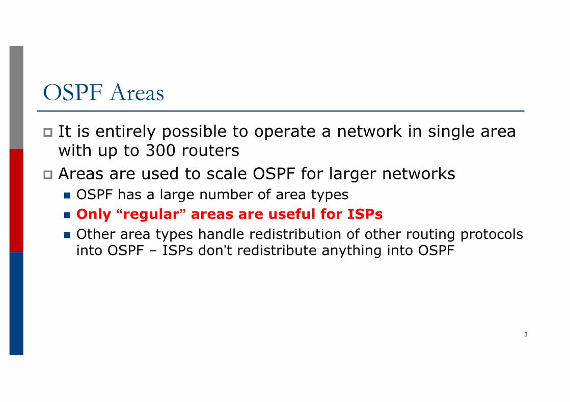
OSPF Areasp It is entirely possible to operate a network in single area
with up to 300 routersp Areas are used to scale OSPF for larger networks
n OSPF has a large number of area typesn Only “regular” areas are useful for ISPsn Other area types handle redistribution of other routing protocols
into OSPF – ISPs don’t redistribute anything into OSPF
3
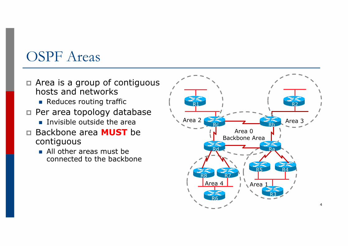
OSPF Areasp Area is a group of contiguous
hosts and networksn Reduces routing traffic
p Per area topology databasen Invisible outside the area
p Backbone area MUST be contiguousn All other areas must be
connected to the backbone
4
Area 1
Area 2 Area 3
R1 R2
R3R6
Area 4
R5 R4R7R8
RaRd
RbRcArea 0
Backbone Area
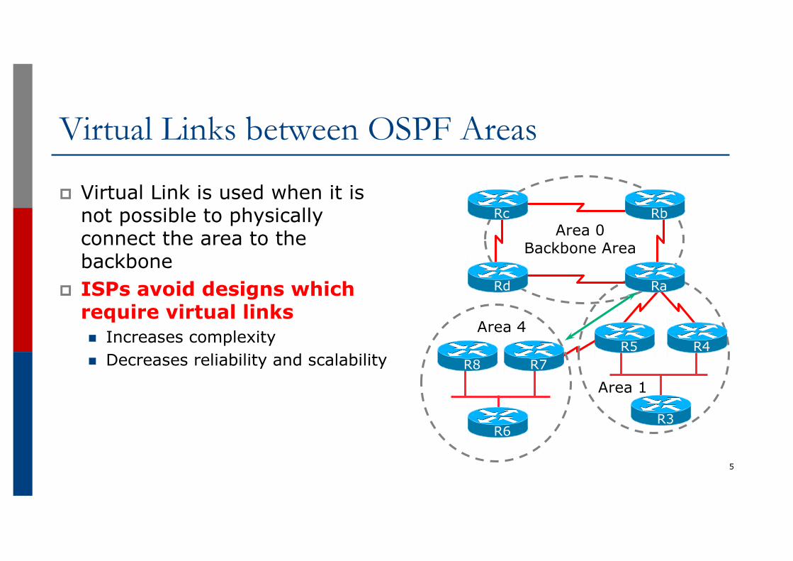
Virtual Links between OSPF Areas
p Virtual Link is used when it is not possible to physically connect the area to the backbone
p ISPs avoid designs which require virtual linksn Increases complexityn Decreases reliability and scalability
5
Area 1
R3R6
Area 4R5 R4
R7R8
RaRd
RbRcArea 0
Backbone Area
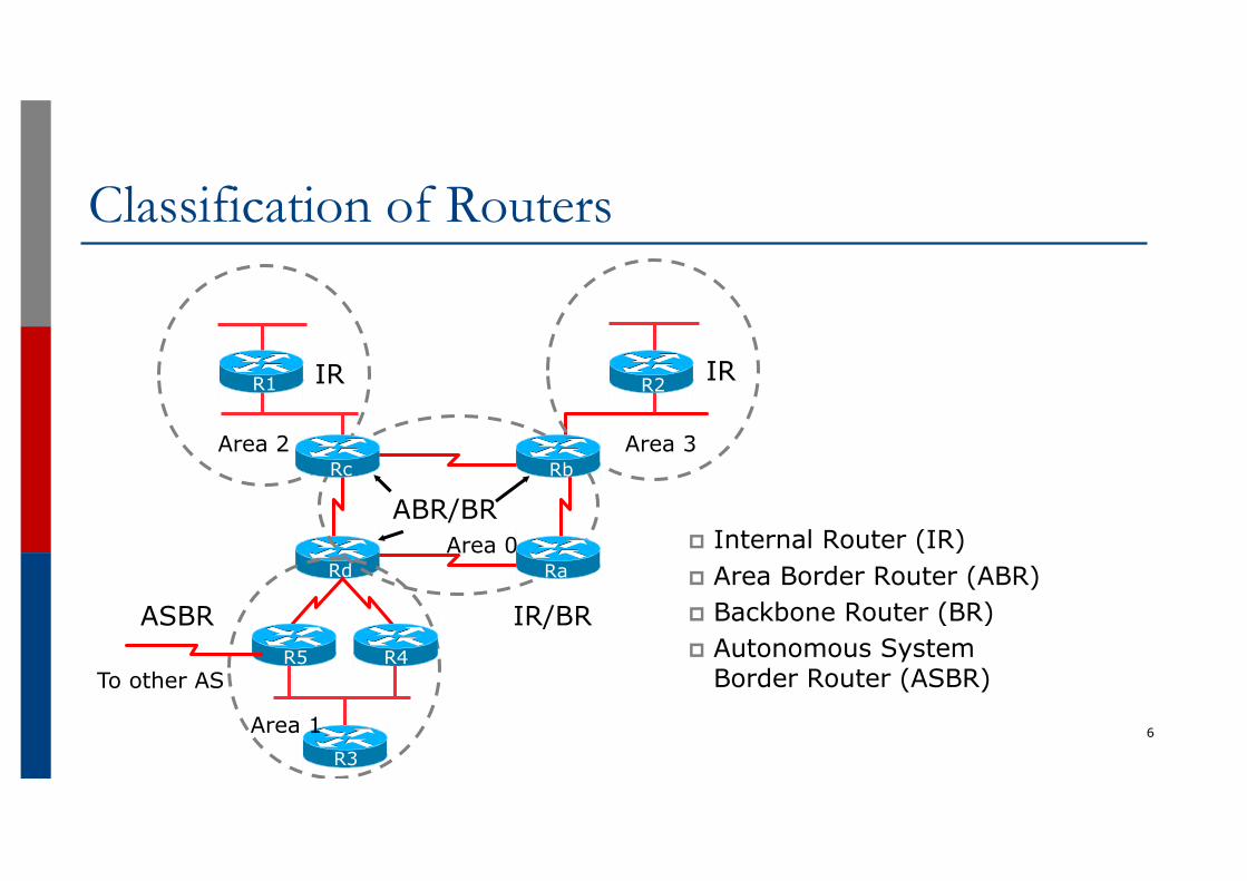
Classification of Routers
p Internal Router (IR)p Area Border Router (ABR)p Backbone Router (BR)p Autonomous System
Border Router (ASBR)
6
R1 R2
R3
R5 R4
Rd Ra
RbRc
IR
ABR/BR
IR/BRASBR
To other AS
IR
Area 1
Area 0
Area 2 Area 3
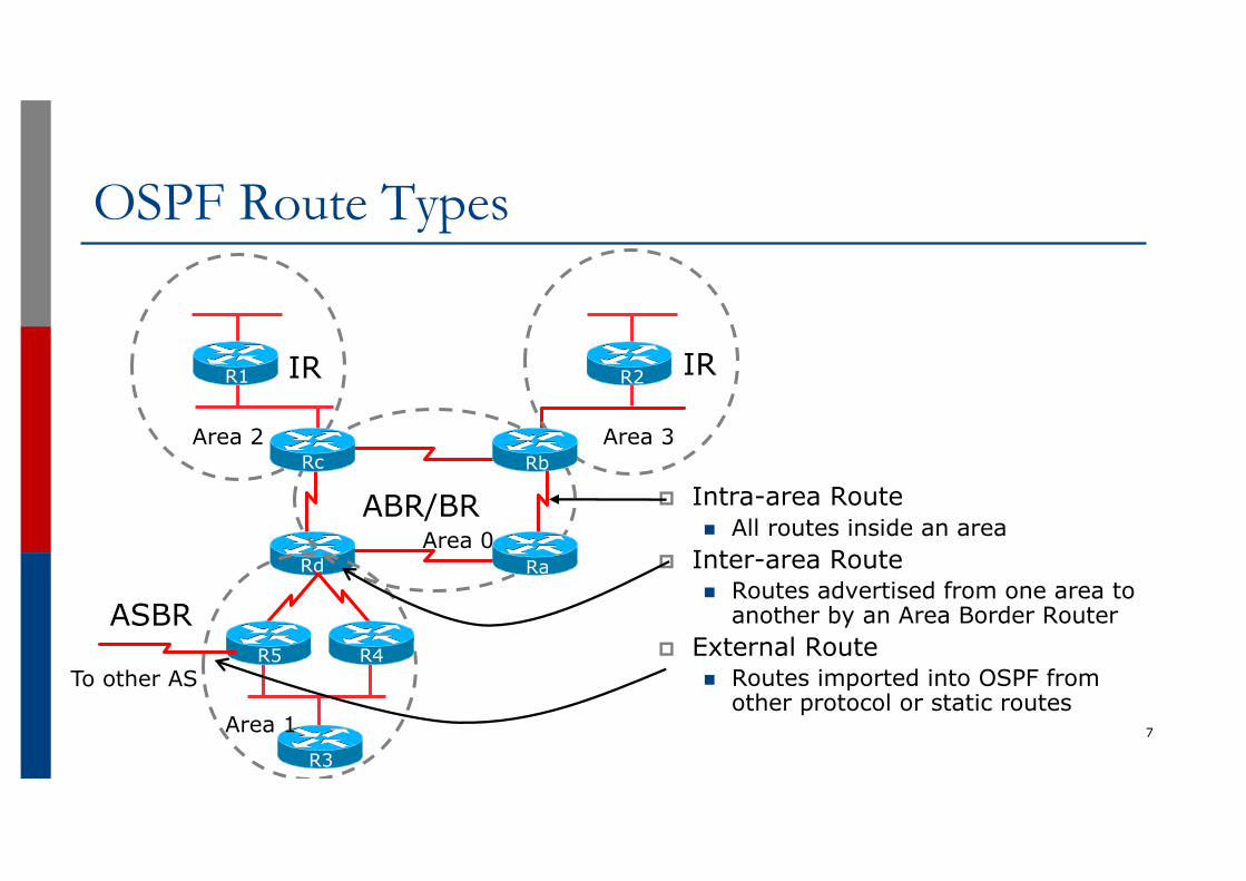
OSPF Route Types
p Intra-area Routen All routes inside an area
p Inter-area Routen Routes advertised from one area to
another by an Area Border Routerp External Route
n Routes imported into OSPF from other protocol or static routes
7
R1 R2
R3
R5 R4
Rd Ra
RbRc
IR
ABR/BR
ASBR
To other AS
IR
Area 1
Area 0
Area 2 Area 3
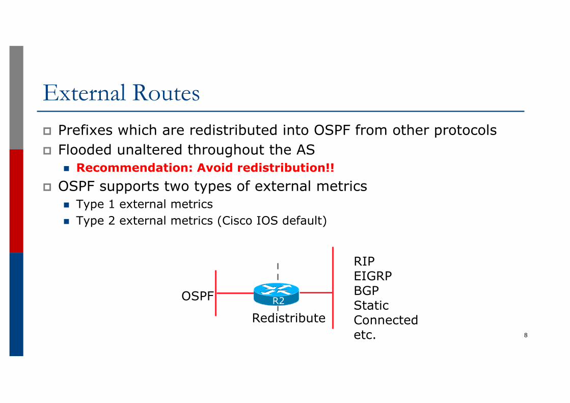
External Routesp Prefixes which are redistributed into OSPF from other protocolsp Flooded unaltered throughout the AS
n Recommendation: Avoid redistribution!!p OSPF supports two types of external metrics
n Type 1 external metricsn Type 2 external metrics (Cisco IOS default)
8
RIPEIGRPBGPStaticConnectedetc.
OSPF
RedistributeR2
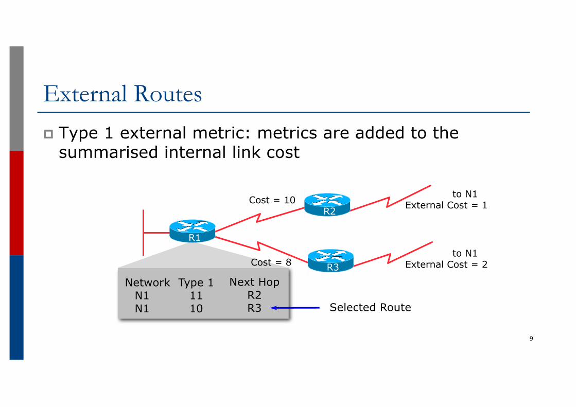
External Routesp Type 1 external metric: metrics are added to the
summarised internal link cost
9
NetworkN1N1
Type 11110
Next HopR2R3
Cost = 10 to N1 External Cost = 1
to N1 External Cost = 2Cost = 8
Selected Route
R3
R1
R2
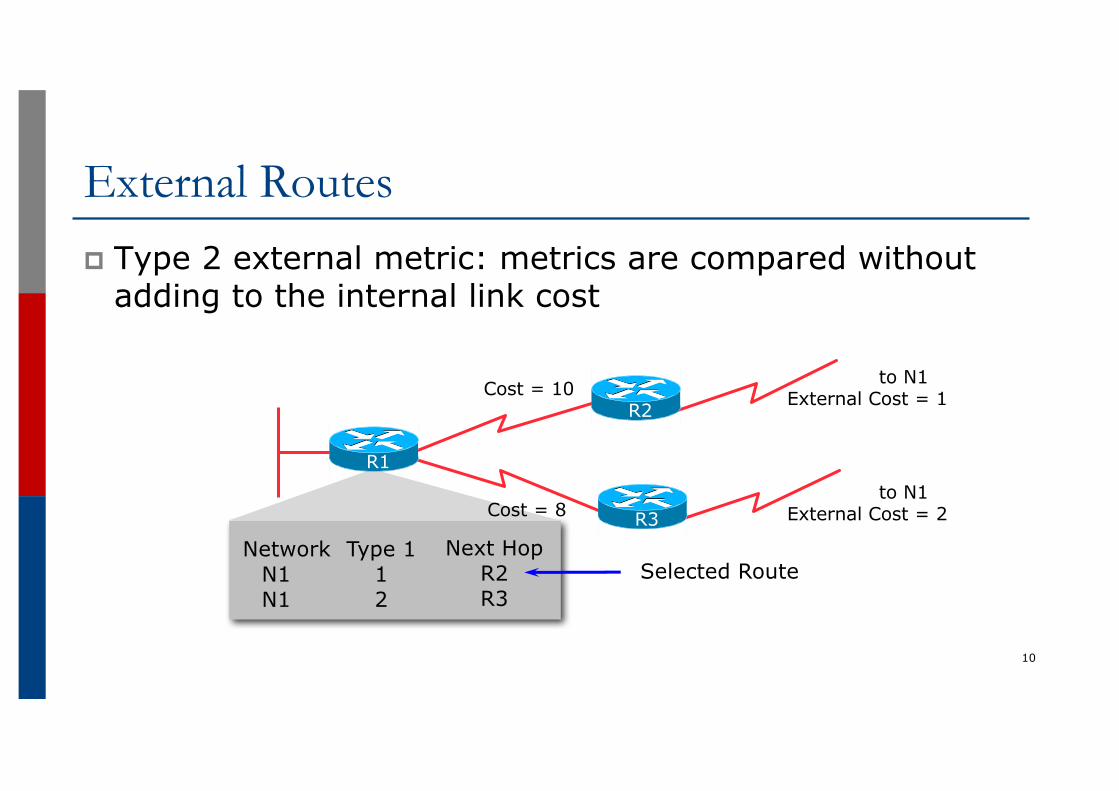
External Routesp Type 2 external metric: metrics are compared without
adding to the internal link cost
10
NetworkN1N1
Type 112
Next HopR2R3
Cost = 10 to N1 External Cost = 1
to N1 External Cost = 2Cost = 8
Selected Route
R3
R1
R2
Topology/Link State Databasep A router has a separate LS database for each area to which it
belongsp All routers belonging to the same area have identical databasep SPF calculation is performed separately for each areap LSA flooding is bounded by areap Recommendation:
n Limit the number of areas a router participates in!!n 1 to 3 is fine (typical ISP design)n >3 can overload the CPU depending on the area topology complexity
11
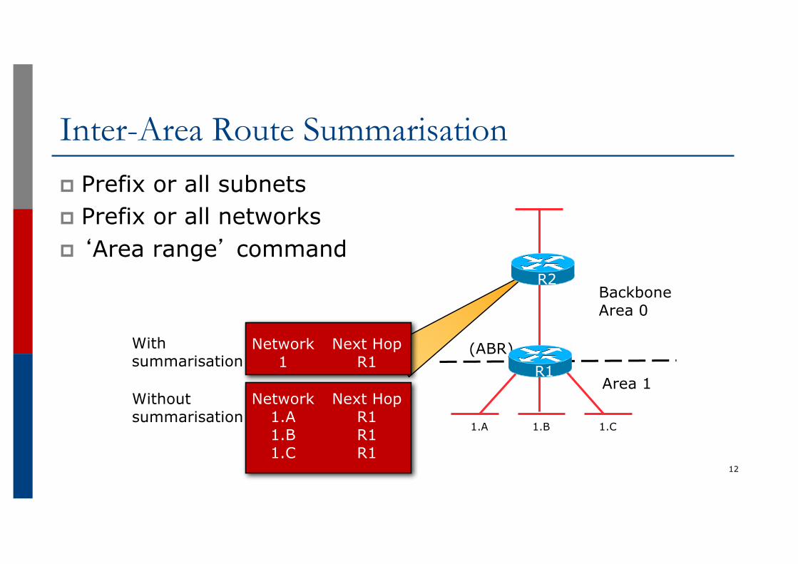
Inter-Area Route Summarisationp Prefix or all subnetsp Prefix or all networksp ‘Area range’ command
12
1.A 1.B 1.C
(ABR)Network1
Next HopR1
Network1.A1.B1.C
Next HopR1R1R1
With summarisation
Withoutsummarisation
BackboneArea 0
Area 1R1
R2
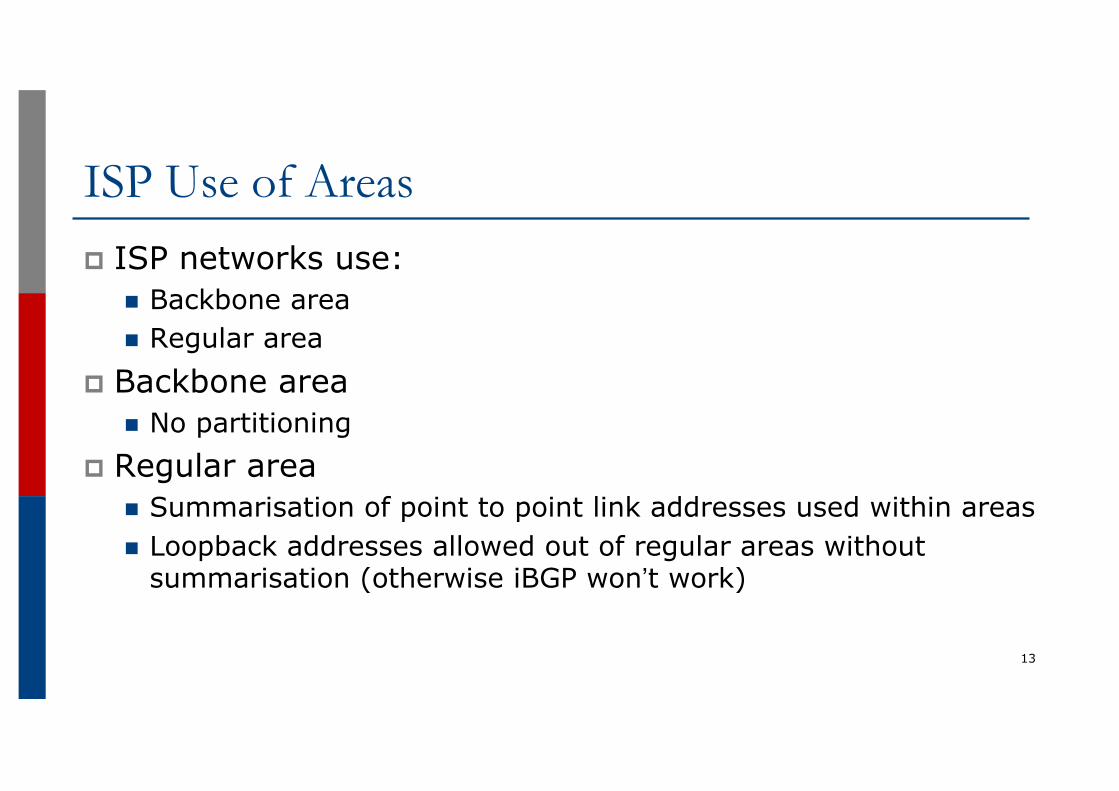
ISP Use of Areasp ISP networks use:
n Backbone arean Regular area
p Backbone arean No partitioning
p Regular arean Summarisation of point to point link addresses used within areasn Loopback addresses allowed out of regular areas without
summarisation (otherwise iBGP won’t work)
13
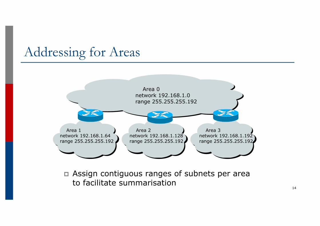
Addressing for Areas
p Assign contiguous ranges of subnets per area to facilitate summarisation
14
Area 1network 192.168.1.64range 255.255.255.192
Area 2network 192.168.1.128range 255.255.255.192
Area 3network 192.168.1.192range 255.255.255.192
Area 0network 192.168.1.0range 255.255.255.192
OSPF for Service Providers
Configuring OSPF & Adding Networks
15
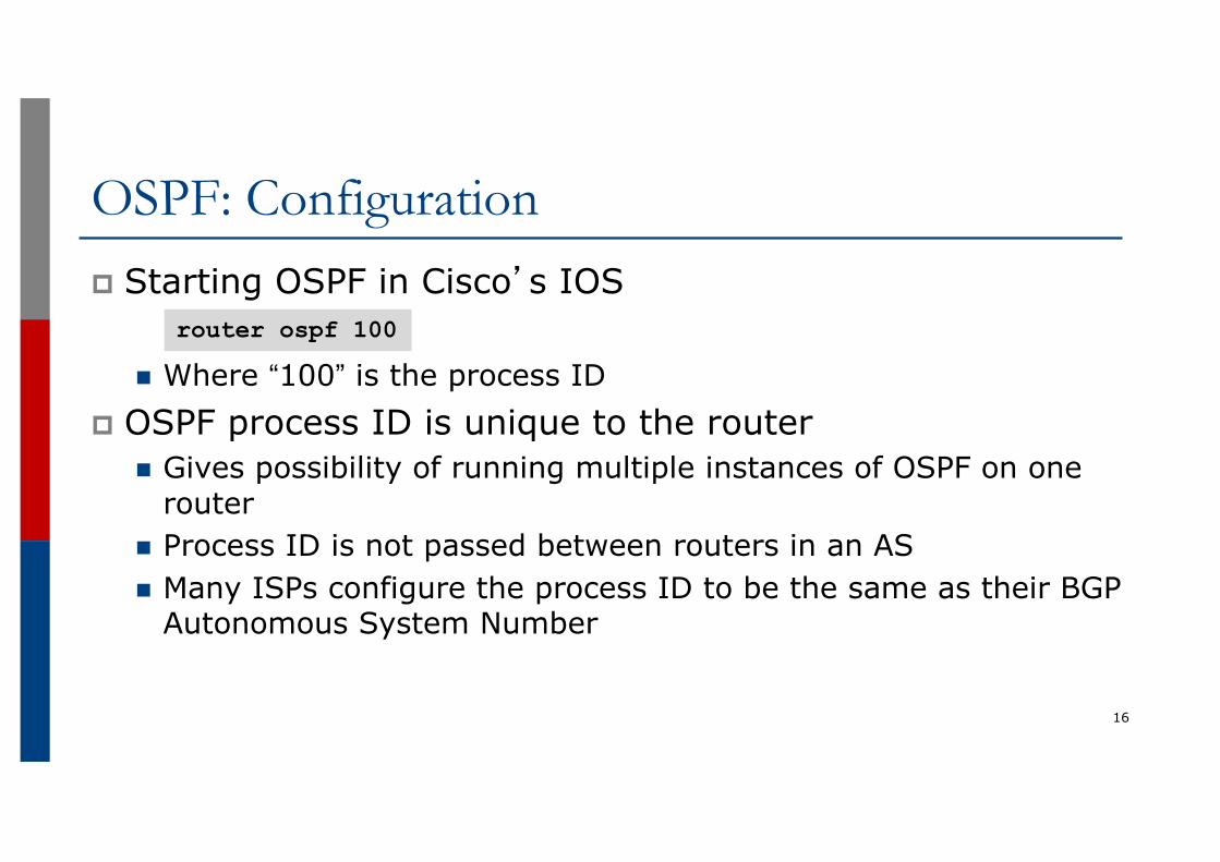
OSPF: Configurationp Starting OSPF in Cisco’s IOS
n Where “100” is the process IDp OSPF process ID is unique to the router
n Gives possibility of running multiple instances of OSPF on one router
n Process ID is not passed between routers in an ASn Many ISPs configure the process ID to be the same as their BGP
Autonomous System Number
16
router ospf 100
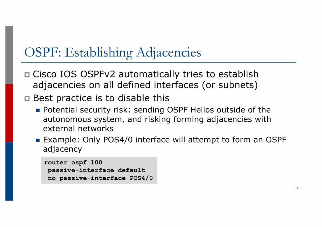
OSPF: Establishing Adjacenciesp Cisco IOS OSPFv2 automatically tries to establish
adjacencies on all defined interfaces (or subnets)p Best practice is to disable this
n Potential security risk: sending OSPF Hellos outside of the autonomous system, and risking forming adjacencies with external networks
n Example: Only POS4/0 interface will attempt to form an OSPF adjacency
17
router ospf 100passive-interface defaultno passive-interface POS4/0

OSPF: Adding NetworksOption Onep Redistribution:
n Applies to all connected interfaces on the router but sends networks as external type-2s – which are not summarised
p Do NOT do this! Because:n Type-2 LSAs flood through entire networkn These LSAs are not all useful for determining paths through backbone; they
simply take up valuable space
18
router ospf 100redistribute connected subnets
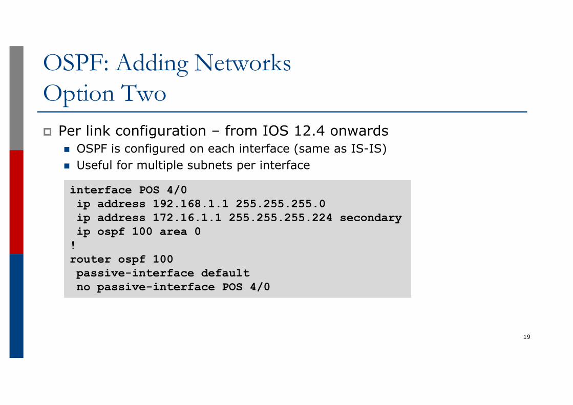
OSPF: Adding NetworksOption Twop Per link configuration – from IOS 12.4 onwards
n OSPF is configured on each interface (same as IS-IS)n Useful for multiple subnets per interface
19
interface POS 4/0ip address 192.168.1.1 255.255.255.0ip address 172.16.1.1 255.255.255.224 secondaryip ospf 100 area 0!router ospf 100passive-interface defaultno passive-interface POS 4/0
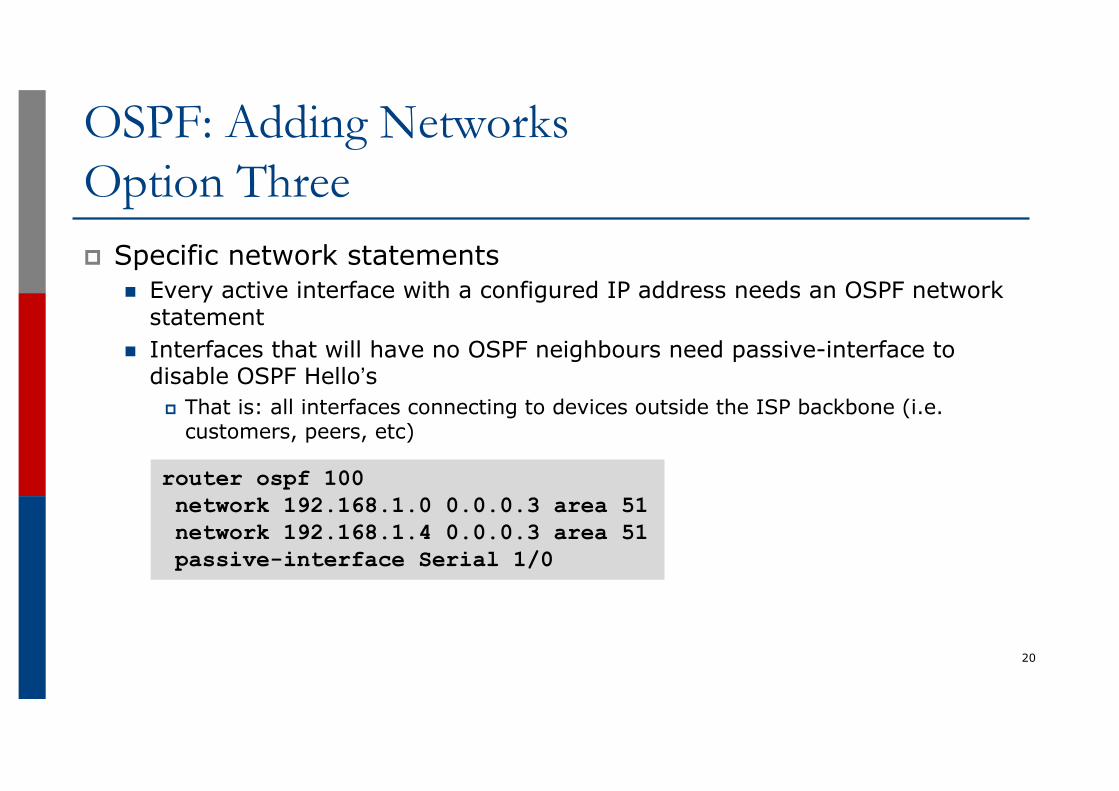
OSPF: Adding NetworksOption Threep Specific network statements
n Every active interface with a configured IP address needs an OSPF network statement
n Interfaces that will have no OSPF neighbours need passive-interface to disable OSPF Hello’s
p That is: all interfaces connecting to devices outside the ISP backbone (i.e. customers, peers, etc)
20
router ospf 100network 192.168.1.0 0.0.0.3 area 51network 192.168.1.4 0.0.0.3 area 51passive-interface Serial 1/0
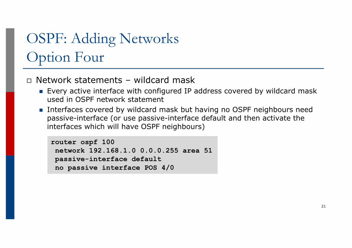
OSPF: Adding NetworksOption Fourp Network statements – wildcard mask
n Every active interface with configured IP address covered by wildcard mask used in OSPF network statement
n Interfaces covered by wildcard mask but having no OSPF neighbours need passive-interface (or use passive-interface default and then activate the interfaces which will have OSPF neighbours)
21
router ospf 100network 192.168.1.0 0.0.0.255 area 51passive-interface defaultno passive interface POS 4/0
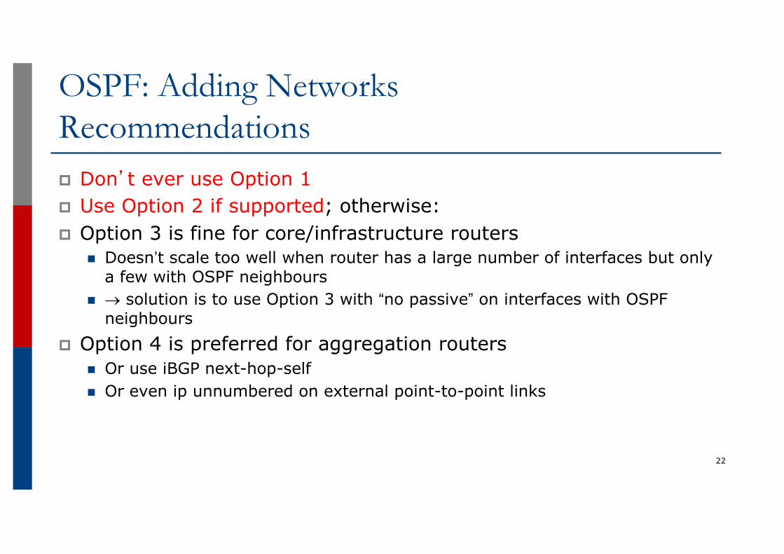
OSPF: Adding NetworksRecommendationsp Don’t ever use Option 1p Use Option 2 if supported; otherwise:p Option 3 is fine for core/infrastructure routers
n Doesn’t scale too well when router has a large number of interfaces but only a few with OSPF neighbours
n ® solution is to use Option 3 with “no passive” on interfaces with OSPF neighbours
p Option 4 is preferred for aggregation routersn Or use iBGP next-hop-selfn Or even ip unnumbered on external point-to-point links
22
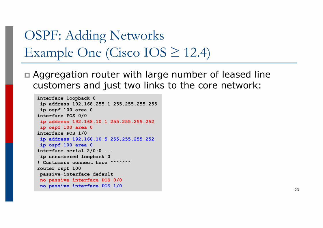
OSPF: Adding NetworksExample One (Cisco IOS ≥ 12.4)p Aggregation router with large number of leased line
customers and just two links to the core network:
23
interface loopback 0ip address 192.168.255.1 255.255.255.255ip ospf 100 area 0
interface POS 0/0ip address 192.168.10.1 255.255.255.252ip ospf 100 area 0
interface POS 1/0ip address 192.168.10.5 255.255.255.252ip ospf 100 area 0
interface serial 2/0:0 ...ip unnumbered loopback 0
! Customers connect here ^^^^^^^router ospf 100passive-interface defaultno passive interface POS 0/0no passive interface POS 1/0
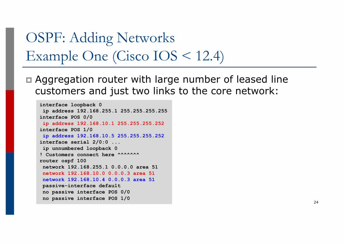
OSPF: Adding NetworksExample One (Cisco IOS < 12.4)p Aggregation router with large number of leased line
customers and just two links to the core network:
24
interface loopback 0ip address 192.168.255.1 255.255.255.255
interface POS 0/0ip address 192.168.10.1 255.255.255.252
interface POS 1/0ip address 192.168.10.5 255.255.255.252
interface serial 2/0:0 ...ip unnumbered loopback 0
! Customers connect here ^^^^^^^router ospf 100network 192.168.255.1 0.0.0.0 area 51network 192.168.10.0 0.0.0.3 area 51network 192.168.10.4 0.0.0.3 area 51passive-interface defaultno passive interface POS 0/0no passive interface POS 1/0

OSPF: Adding NetworksExample Two (Cisco IOS ≥ 12.4)p Core router with only links to other core routers:
25
interface loopback 0ip address 192.168.255.1 255.255.255.255ip ospf 100 area 0
interface POS 0/0ip address 192.168.10.129 255.255.255.252ip ospf 100 area 0
interface POS 1/0ip address 192.168.10.133 255.255.255.252ip ospf 100 area 0
interface POS 2/0ip address 192.168.10.137 255.255.255.252ip ospf 100 area 0
interface POS 2/1ip address 192.168.10.141 255.255.255.252ip ospf 100 area 0
router ospf 100passive interface loopback 0
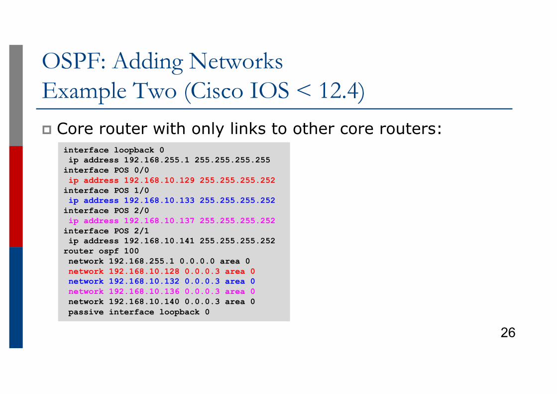
OSPF: Adding NetworksExample Two (Cisco IOS < 12.4)p Core router with only links to other core routers:
26
interface loopback 0ip address 192.168.255.1 255.255.255.255
interface POS 0/0ip address 192.168.10.129 255.255.255.252
interface POS 1/0ip address 192.168.10.133 255.255.255.252
interface POS 2/0ip address 192.168.10.137 255.255.255.252
interface POS 2/1ip address 192.168.10.141 255.255.255.252
router ospf 100network 192.168.255.1 0.0.0.0 area 0network 192.168.10.128 0.0.0.3 area 0network 192.168.10.132 0.0.0.3 area 0network 192.168.10.136 0.0.0.3 area 0network 192.168.10.140 0.0.0.3 area 0passive interface loopback 0
OSPF: Adding NetworksSummaryp Key Theme when selecting a technique: Keep the Link
State Database Leann Increases Stabilityn Reduces the amount of information in the Link State
Advertisements (LSAs)n Speeds Convergence Time
27
OSPF for Service Providers
Network Design
28
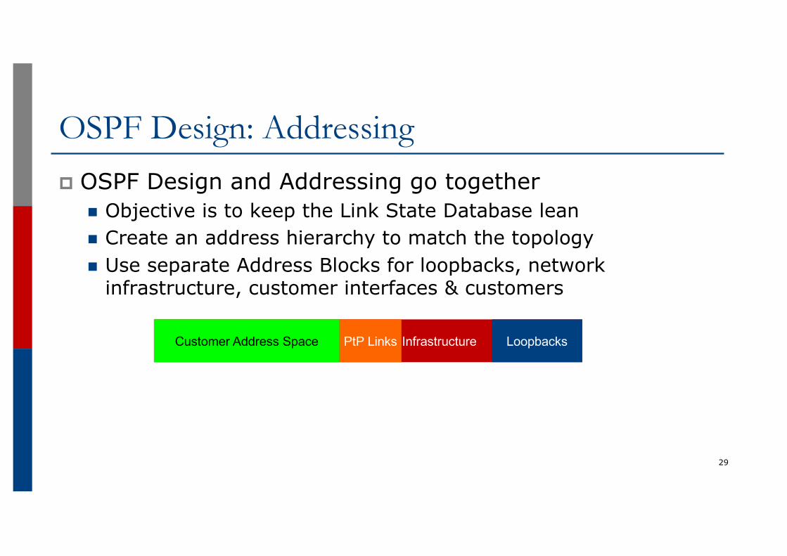
OSPF Design: Addressingp OSPF Design and Addressing go together
n Objective is to keep the Link State Database leann Create an address hierarchy to match the topologyn Use separate Address Blocks for loopbacks, network
infrastructure, customer interfaces & customers
29
InfrastructureCustomer Address Space LoopbacksPtP Links
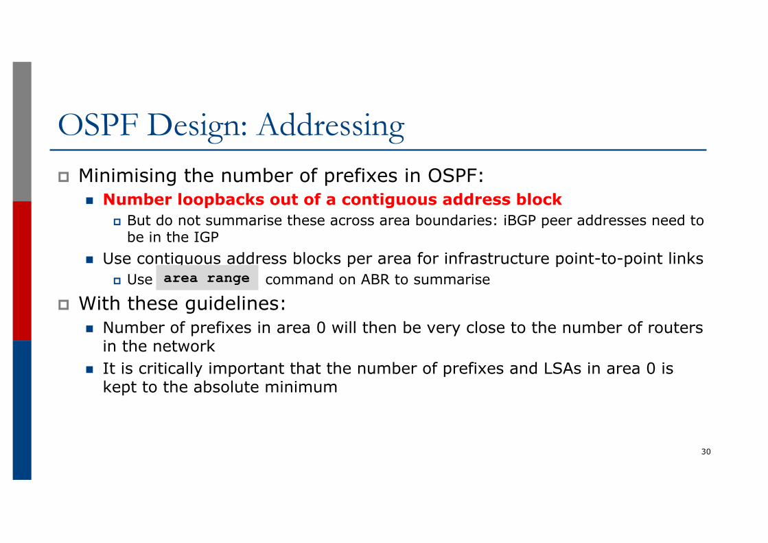
OSPF Design: Addressingp Minimising the number of prefixes in OSPF:
n Number loopbacks out of a contiguous address blockp But do not summarise these across area boundaries: iBGP peer addresses need to
be in the IGPn Use contiguous address blocks per area for infrastructure point-to-point links
p Use command on ABR to summarise
p With these guidelines:n Number of prefixes in area 0 will then be very close to the number of routers
in the networkn It is critically important that the number of prefixes and LSAs in area 0 is
kept to the absolute minimum
30
area range
OSPF Design: Areasp Examine physical topology
n Is it meshed or hub-and-spoke?p Use areas and summarisation
n This reduces overhead and LSA countsn (but watch next-hop for iBGP when summarising)
p Don’t bother with the various stub areasn No benefits for ISPs, causes problems for iBGP
p Push the creation of a backbonen Reduces mesh and promotes hierarchy
31
OSPF Design: Areasp One SPF per area, flooding done per area
n Watch out for overloading ABRsp Avoid externals in OSPF
n DO NOT REDISTRIBUTE into OSPFn External LSAs flood through entire network
p Different types of areas do different floodingn Normal areasn Stub areasn Totally stubby (stub no-summary)n Not so stubby areas (NSSA)
32
OSPF Design: Areasp Area 0 must be contiguous
n Do NOT use virtual links to join two Area 0 islandsp Traffic between two non-zero areas always goes via Area 0
n There is no benefit in joining two non-zero areas togethern Avoid designs which have two non-zero areas touching each othern (Typical design is an area per PoP, with core routers being ABR to the
backbone area 0)
33
OSPF Design: Summaryp Think Redundancy
n Dual Links out of each area – using metrics (cost) for traffic engineering
p Too much redundancy…n Dual links to backbone in stub areas must be the same cost –
other wise sub-optimal routing will resultn Too Much Redundancy in the backbone area without good
summarisation will effect convergence in the Area 0
34
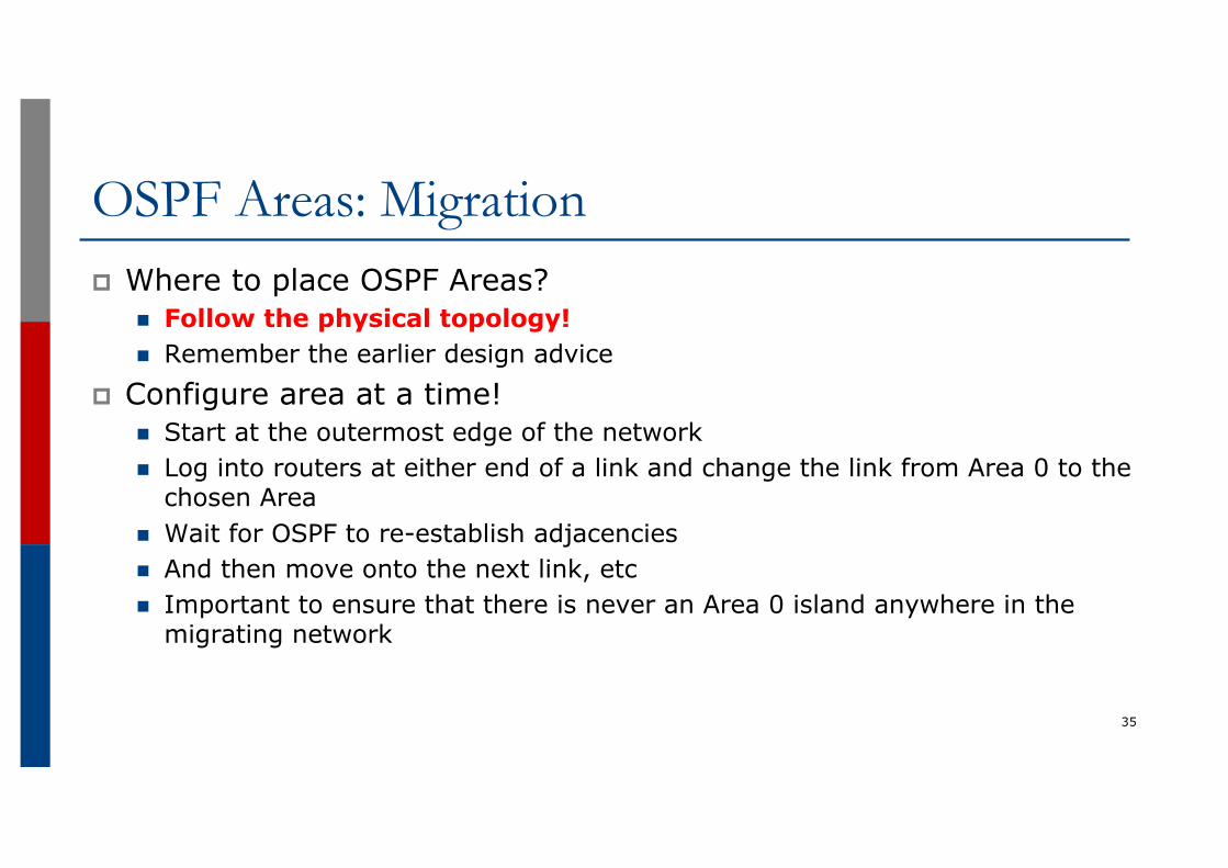
OSPF Areas: Migrationp Where to place OSPF Areas?
n Follow the physical topology!n Remember the earlier design advice
p Configure area at a time!n Start at the outermost edge of the networkn Log into routers at either end of a link and change the link from Area 0 to the
chosen Arean Wait for OSPF to re-establish adjacenciesn And then move onto the next link, etcn Important to ensure that there is never an Area 0 island anywhere in the
migrating network
35
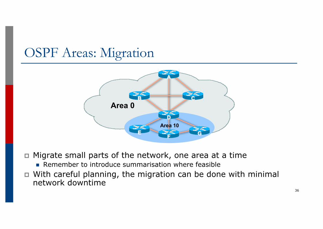
OSPF Areas: Migration
p Migrate small parts of the network, one area at a timen Remember to introduce summarisation where feasible
p With careful planning, the migration can be done with minimal network downtime
36
Area 0
A
B
GFE
D
C
Area 10
OSPF for Service Providers
Useful features for ISPs
37
Areas
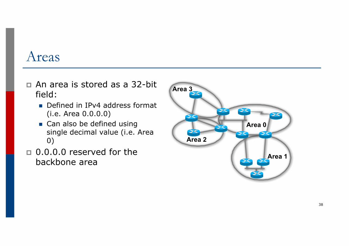
p An area is stored as a 32-bit field:n Defined in IPv4 address format
(i.e. Area 0.0.0.0) n Can also be defined using
single decimal value (i.e. Area 0)
p 0.0.0.0 reserved for the backbone area
38
Area 0
Area 1
Area 2
Area 3
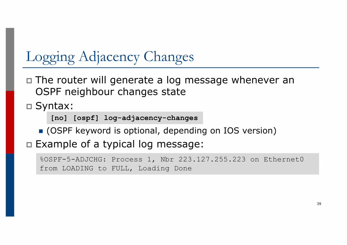
Logging Adjacency Changesp The router will generate a log message whenever an
OSPF neighbour changes state p Syntax:
n (OSPF keyword is optional, depending on IOS version)p Example of a typical log message:
39
[no] [ospf] log-adjacency-changes
%OSPF-5-ADJCHG: Process 1, Nbr 223.127.255.223 on Ethernet0 from LOADING to FULL, Loading Done
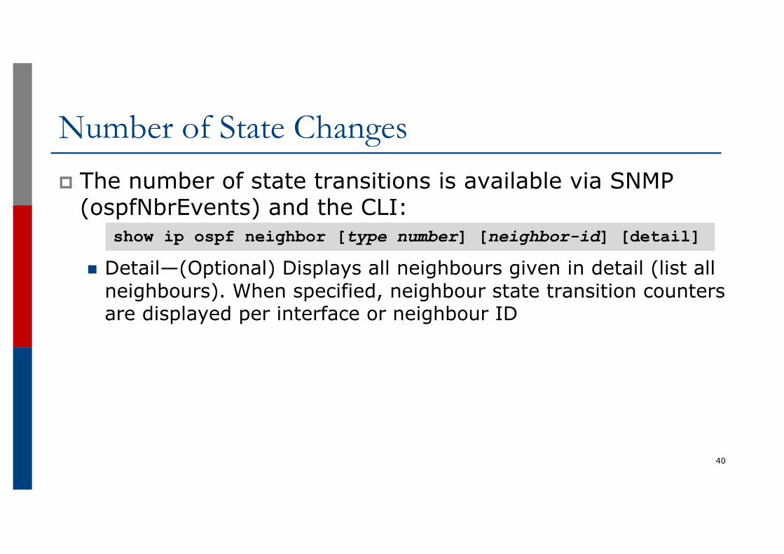
Number of State Changesp The number of state transitions is available via SNMP
(ospfNbrEvents) and the CLI:
n Detail—(Optional) Displays all neighbours given in detail (list all neighbours). When specified, neighbour state transition counters are displayed per interface or neighbour ID
40
show ip ospf neighbor [type number] [neighbor-id] [detail]
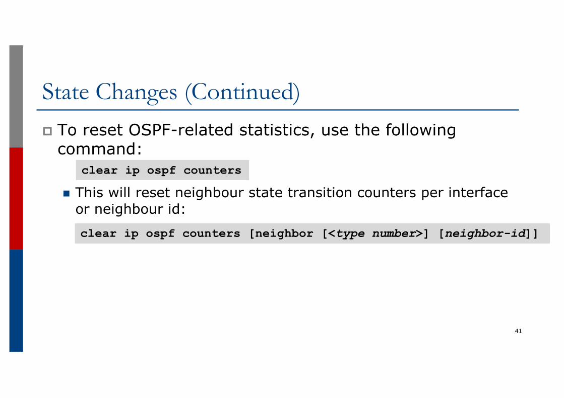
State Changes (Continued)p To reset OSPF-related statistics, use the following
command:
n This will reset neighbour state transition counters per interface or neighbour id:
41
clear ip ospf counters
clear ip ospf counters [neighbor [<type number>] [neighbor-id]]
Router ID
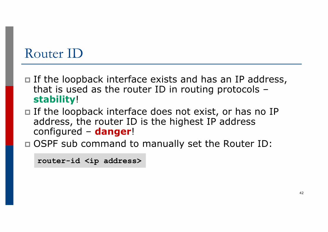
p If the loopback interface exists and has an IP address, that is used as the router ID in routing protocols –stability!
p If the loopback interface does not exist, or has no IP address, the router ID is the highest IP address configured – danger!
p OSPF sub command to manually set the Router ID:
42
router-id <ip address>
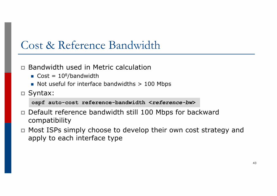
Cost & Reference Bandwidth
p Bandwidth used in Metric calculationn Cost = 108/bandwidthn Not useful for interface bandwidths > 100 Mbps
p Syntax:
p Default reference bandwidth still 100 Mbps for backward compatibility
p Most ISPs simply choose to develop their own cost strategy and apply to each interface type
43
ospf auto-cost reference-bandwidth <reference-bw>
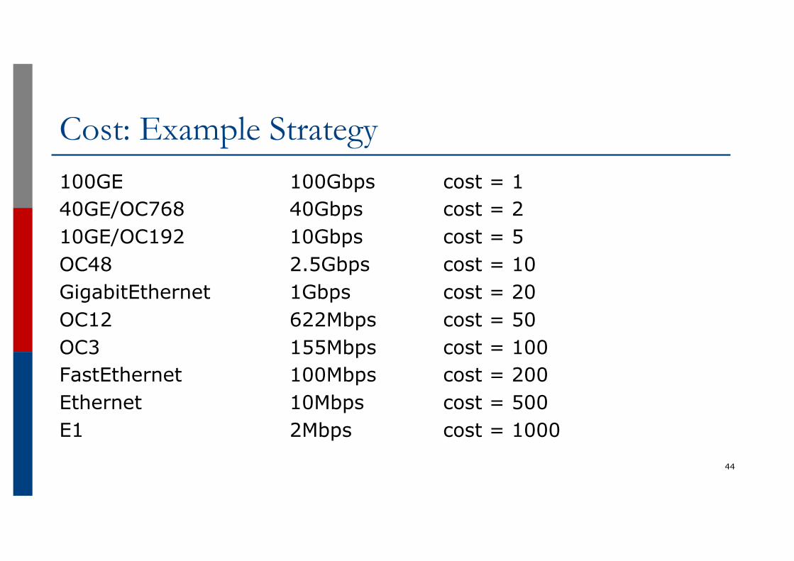
Cost: Example Strategy100GE 100Gbps cost = 140GE/OC768 40Gbps cost = 210GE/OC192 10Gbps cost = 5OC48 2.5Gbps cost = 10GigabitEthernet 1Gbps cost = 20OC12 622Mbps cost = 50OC3 155Mbps cost = 100FastEthernet 100Mbps cost = 200Ethernet 10Mbps cost = 500E1 2Mbps cost = 1000
44
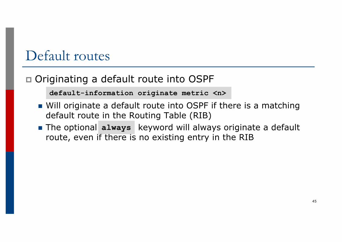
Default routesp Originating a default route into OSPF
n Will originate a default route into OSPF if there is a matching default route in the Routing Table (RIB)
n The optional keyword will always originate a default route, even if there is no existing entry in the RIB
45
default-information originate metric <n>
always
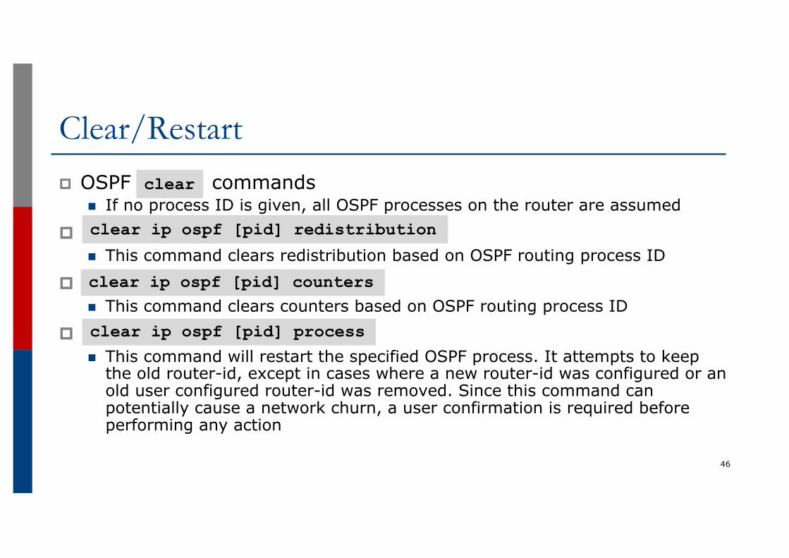
Clear/Restartp OSPF commands
n If no process ID is given, all OSPF processes on the router are assumed
pn This command clears redistribution based on OSPF routing process ID
pn This command clears counters based on OSPF routing process ID
pn This command will restart the specified OSPF process. It attempts to keep
the old router-id, except in cases where a new router-id was configured or an old user configured router-id was removed. Since this command can potentially cause a network churn, a user confirmation is required before performing any action
46
clear
clear ip ospf [pid] redistribution
clear ip ospf [pid] counters
clear ip ospf [pid] process
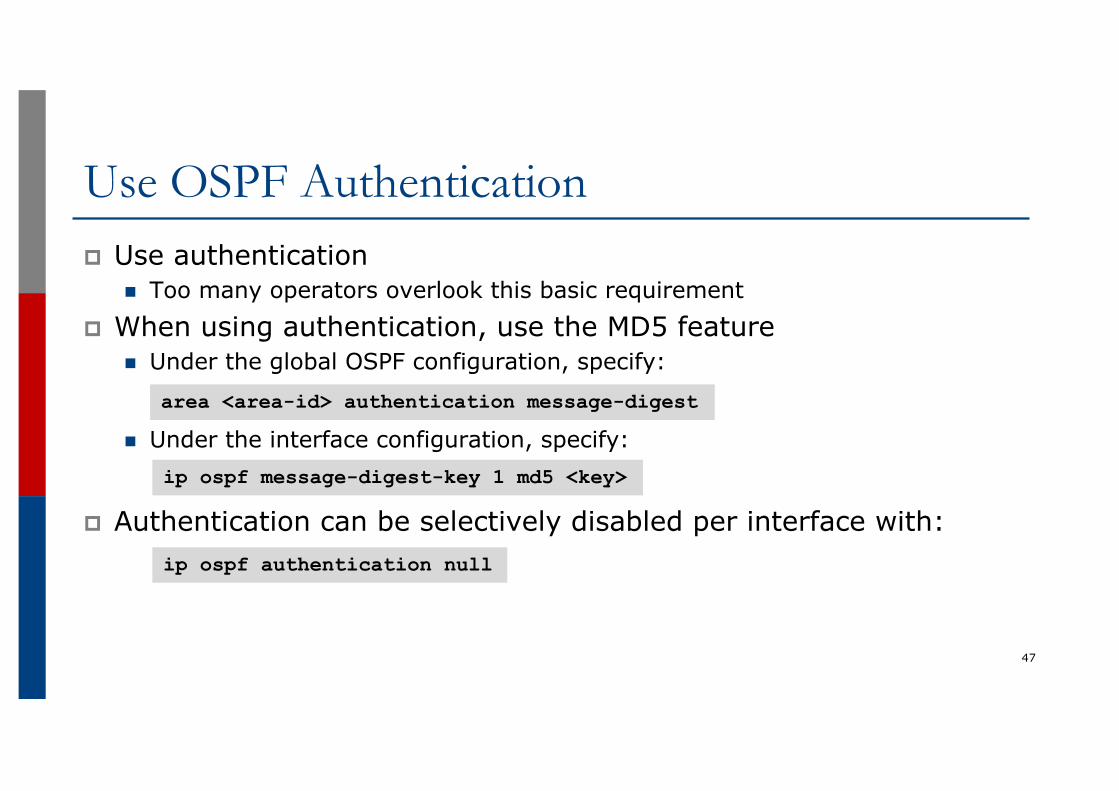
Use OSPF Authenticationp Use authentication
n Too many operators overlook this basic requirementp When using authentication, use the MD5 feature
n Under the global OSPF configuration, specify:
n Under the interface configuration, specify:
p Authentication can be selectively disabled per interface with:
47
area <area-id> authentication message-digest
ip ospf message-digest-key 1 md5 <key>
ip ospf authentication null
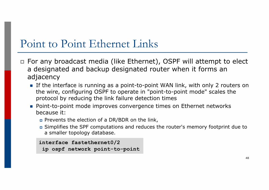
Point to Point Ethernet Linksp For any broadcast media (like Ethernet), OSPF will attempt to elect
a designated and backup designated router when it forms an adjacencyn If the interface is running as a point-to-point WAN link, with only 2 routers on
the wire, configuring OSPF to operate in "point-to-point mode" scales the protocol by reducing the link failure detection times
n Point-to-point mode improves convergence times on Ethernet networks because it:
p Prevents the election of a DR/BDR on the link,p Simplifies the SPF computations and reduces the router's memory footprint due to
a smaller topology database.
48
interface fastethernet0/2ip ospf network point-to-point
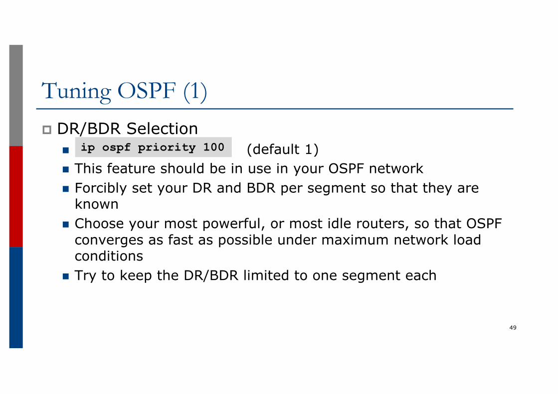
Tuning OSPF (1)p DR/BDR Selection
n (default 1)n This feature should be in use in your OSPF networkn Forcibly set your DR and BDR per segment so that they are
knownn Choose your most powerful, or most idle routers, so that OSPF
converges as fast as possible under maximum network load conditions
n Try to keep the DR/BDR limited to one segment each
49
ip ospf priority 100
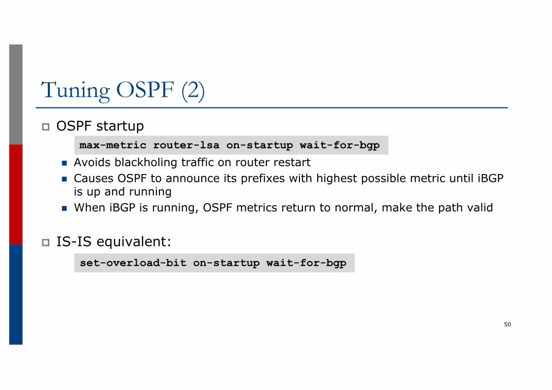
Tuning OSPF (2)p OSPF startup
n Avoids blackholing traffic on router restart n Causes OSPF to announce its prefixes with highest possible metric until iBGP
is up and runningn When iBGP is running, OSPF metrics return to normal, make the path valid
p IS-IS equivalent:
50
max-metric router-lsa on-startup wait-for-bgp
set-overload-bit on-startup wait-for-bgp
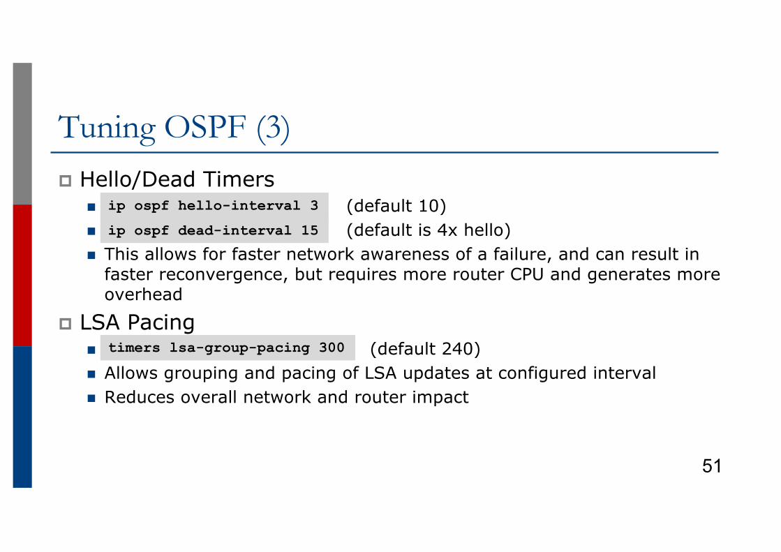
Tuning OSPF (3)p Hello/Dead Timers
n (default 10)n (default is 4x hello)n This allows for faster network awareness of a failure, and can result in
faster reconvergence, but requires more router CPU and generates more overhead
p LSA Pacingn (default 240)n Allows grouping and pacing of LSA updates at configured intervaln Reduces overall network and router impact
51
ip ospf hello-interval 3
ip ospf dead-interval 15
timers lsa-group-pacing 300
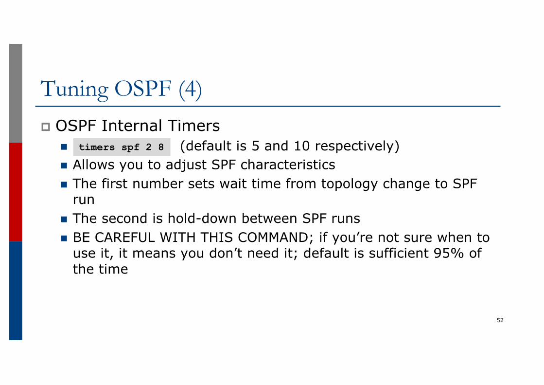
Tuning OSPF (4)p OSPF Internal Timers
n (default is 5 and 10 respectively)n Allows you to adjust SPF characteristicsn The first number sets wait time from topology change to SPF
runn The second is hold-down between SPF runsn BE CAREFUL WITH THIS COMMAND; if you’re not sure when to
use it, it means you don’t need it; default is sufficient 95% of the time
52
timers spf 2 8
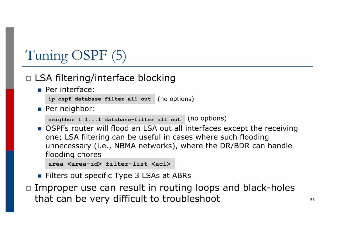
Tuning OSPF (5)p LSA filtering/interface blocking
n Per interface:p (no options)
n Per neighbor:p (no options)
n OSPFs router will flood an LSA out all interfaces except the receiving one; LSA filtering can be useful in cases where such flooding unnecessary (i.e., NBMA networks), where the DR/BDR can handle flooding chores
n Filters out specific Type 3 LSAs at ABRs
p Improper use can result in routing loops and black-holes that can be very difficult to troubleshoot 53
ip ospf database-filter all out
neighbor 1.1.1.1 database-filter all out
area <area-id> filter-list <acl>
Summaryp OSPF has a bewildering number of features and optionsp Observe ISP best practicesp Keep design and configuration simplep Investigate tuning options and suitability for your own
networkn Don’t just turn them on!
54
OSPF for ISPs
ISP Workshops
55