Embed Size (px)
Citation preview

OSPE Steering ValveSASA Sensor
Technical Information
2
F500 026
11068682 • Rev CD • Sep 2012
OSPE Steering ValveTechnical Information
© 2012 Sauer-Danfoss. All rights reserved.Sauer-Danfoss accepts no responsibility for possible errors in catalogs, brochures and other printed material. Sauer -Danfoss reserves the right to alter its products without prior notice. This also applies to products already ordered provided that such alterations can be made without aff ecting agreed specifi cations. All trademarks in this material are properties of their respective owners. Sauer-Danfoss, the Sauer-Danfoss logotype, the Sauer-Danfoss S-icon, PLUS+1™, What really matters is inside® and Know-How in Motion™ are trademarks of the Sauer-Danfoss Group.
Revisions, A Wide Range of Steering Components
Table of RevisionsDate Page Changed RevAug 2009 All First edition AAOct 2009 Many Major change BAJul 2011 27 Flow Characteristics added CAMar 2012 38 Schema changed CBMar 2012 38 ™ added CCSep 2012 22 Tabel updated CD
Revision History
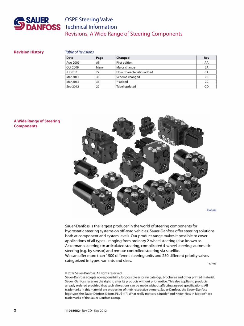
A Wide Range of Steering Components
Sauer-Danfoss is the largest producer in the world of steering components for hydrostatic steering systems on off -road vehicles. Sauer-Danfoss off er steering solutions both at component and system levels. Our product range makes it possible to cover applications of all types - ranging from ordinary 2-wheel steering (also known as Ackermann steering) to articulated steering, complicated 4-wheel steering, automatic steering (e.g. by sensor) and remote controlled steering via satellite.We can off er more than 1500 diff erent steering units and 250 diff erent priority valves categorized in types, variants and sizes.
T301033

311068682 • Rev CD • Sep 2012
OSPE Steering Valve Technical InformationA Wide Range of Steering Components
A Wide Range of Steering Components(continued)
For hydrostatic steering systems Sauer-Danfoss off ers:• Mini steering units with displacements from 32 to 100 cm3/rev [1.95 to 6.10 in3/rev],
fl ow up to 20 l/min [5.28 US gal/min], steering pressure up to 125 bar [1813 psi].• Steering units with displacements from 40 to 1200 cm3/rev [2.44 to 73.2 in3/rev], fl ow
up to 100 l/min [26.4 US gaL/min, steering pressure up to 240 bar [3481 psi].• Priority valves for rated fl ows at 40, 80, 120, 160 and 320 l/min [10.6, 21.1, 31.7, 42.3
and 84.5 US gal/min], pressure up to 350 bar [5076 psi].• Pilot operated fl ow-amplifi ers with amplifi cation factors of 4, 5, 8, 10 or 20 for rated oil
fl ows of 240 and 400 l/min [63.4 and 105.7 US gal/min], steering pressure up to 210 bar [3045 psi].
• Pilot operated steering valve with steering fl ow up to 100 l/min [26.4 US gal/min], steering pressure up to 250 bar [3625 psi] and with integrated priority valve for pump fl ow up to 120 l/min [31.7 US gal/min].
For electro hydraulic steering systems Sauer-Danfoss off ers:• Pilot operated steering valves (pilot operated by hydrostatic steering unit or by
electrical signal) with steering fl ows up to 100 l/min [26.4 US gal/min], steering pressure up to 250 bar [3625 psi].
• Steering units with integrated electrical operated steering valve with steering fl ow up to 50 l/min [13.2 US gal/min], steering pressure up to 210 bar [3045 psi].
• Electrical operated steering valves with steering fl ow up to 40 l/min [10.57 US gal/min], steering pressure up to 210 bar [3045 psi].
Characteristic features for steering units:• Low steering torque: From 0.5 Nm to 3 Nm in normal steering situations• Low noise level• Low pressure drop• Many types available: Open center None reaction, Open center Reaction, Closed
center None reaction, Load Sensing, Load Sensing Reaction• One or more built-in valve functions: relief valve, shock valves, suction valves, none
return valve in P-line and in LS-line• Optional port connections (according to ISO, SAE or DIN standards)
Characteristic features for electrohydraulic steering system:• Electrohydraulic steering valve EHPS: High steering pressure requiring smaller
cylinders and fl ow• EHPS: Low pilot pressure and fl ow giving extremely low noise in the cabin• EHPS: The possibility of manual steering even on very heavy vehicles• EHPS can be combined with Sauer-Danfoss PVG 32 proportional valve• Minimization of side acceleration with articulated steering• Posibility of GPS-, row sensor-, joy stick- steering and vaiable steering ratio
T301034
1 N•m = [8.851 lbf•in] 1 cm3 = [0.061 in3]1 N = [0.2248 lbf ] 1 l = [0.264 US gal]1 bar = [14.50 psi] °F = [1.8°C + 32]1 mm = [0.0394 in]
T301035
Conversion Factors
4 11068682 • Rev CD • Sep 2012
OSPE Steering ValveTechnical InformationTable of Content
A Wide Range of Steering Components................................................................................................. 2Technical Literature Survey......................................................................................................................... 5
General ......................................................................................................................................................... 6Overview ...................................................................................................................................................... 7OSPEC LSRM: ............................................................................................................................................. 8OSPEF LS ...................................................................................................................................................... 9OSPEDC LSRM ..........................................................................................................................................10OSPEDF LS .................................................................................................................................................11PVED-CL......................................................................................................................................................12
OSPE Steering Valve ....................................................................................................................................13OSPEC LSRM Neutral position ............................................................................................................14OSPEC LSRM Steering right with steering wheel ........................................................................16OSPEC LSRM Steering Right with EH ...............................................................................................18PVES and PVED-CL, electrical actuation .........................................................................................20OSPE ............................................................................................................................................................21Weights .......................................................................................................................................................21
Technical Data PVES ....................................................................................................................................22Technical Data PVED-CL .............................................................................................................................22Hysteresis, PVES and PVED-CL .................................................................................................................23Technical Data PVES and PVED-CL .........................................................................................................23Installation PVED-CL ....................................................................................................................................24
Technical Data, Coil of Control Valve for Mode Select ...............................................................25Specifications ...........................................................................................................................................25Electrical Specifications ........................................................................................................................25Terminals ....................................................................................................................................................25Dimensioning Steering System with OSPE Steering Valve ......................................................26EH-Directional Spools of OSPE ..........................................................................................................27Pilot pressure relief valve: (P - T, Qp) characteristic .....................................................................28Pressure drop P-EF for Sauer-Danfoss OSPE Valve ......................................................................29
Dimensions .....................................................................................................................................................31Hydraulic Systems .......................................................................................................................................32
OSPE in a system with fixed gear pump and GPS steering ......................................................32OSPE in a system with variable pump and GPS steering ..........................................................33Emergency Steering ..............................................................................................................................34OSPE and system safety, PVES and PVED CL .................................................................................34Fault monitoring .....................................................................................................................................34
Safety Considerations .................................................................................................................................35Variants and Order Specification ............................................................................................................36Code numbers for catalog versions with specifications ................................................................37Sensor Type SASA General ........................................................................................................................38Versions, Code Numbers and Weights SASA Sensor .......................................................................38Code Number and Weight, SAK Adapter Kit .......................................................................................38CAN Message Protocol ...............................................................................................................................39Parameter Setup ...........................................................................................................................................40Technical Data ...............................................................................................................................................41Dimensions .....................................................................................................................................................42SASA Sensor ...................................................................................................................................................42SAK Adapter Kit .............................................................................................................................................42Installation ......................................................................................................................................................43
Recommended wiring practice .........................................................................................................44
Table of Content
Versions
Function
Technical Data
DimensionsHydraulic Systems
System SafetyOrder SpecificationCode numbersSensor Type SASA
Steering valve Type OSPE
511068682 • Rev CD • Sep 2012
OSPE Steering Valve Technical Information
Survey of Literature with Technical Data on Sauer-Danfoss Steering Components
Detailed data on all Sauer-Danfoss steering components and accessories can be found in our steering component catalogues, which is divided in to 6 individual sub catalogues:
The most important data on all Sauer-Danfoss steering components is highlighted in a general survey brochure.For technical information on individual variants, please contact the Sauer-Danfoss Sales Organization.
T301036
• General information
• Technical data on mini steering units
• Technical data on open center, and closed center steering units
• Technical data on load sensing steering units, priority valves and fl ow amplifi ers
• Technical data on hydraulic and electro-hydraulic pilot operated steering valves, electrical actuation modules and appropriate steering units.
• Technical data on combined steering unit/electro hydraulic steering valves and steering wheel sensors
Steering components
OSPM
OSPB, OSPC, and OSPD
OSPB, OSPC, OSPF, OSPD, OSPQ, OSPL, OSPBX, OSPLX, OVPL, OLS and OSQ
EHPS, EHPS w. OLS 320, PVE for EHPS and OSPCX
OSPE and SASA
Technical Literature Survey

6 11068682 • Rev CD • Sep 2012
OSPE Steering ValveTechnical InformationGeneral
General Steering valve Type OSPE
On tractors, combine harvesters, maize harvesters and other simulate vehicles there is often a need for electrically actuated steering to make automatic GPS controlled steering possible. Also manual steering with variable ratio is an often wanted feature to improve productivity and driver comfort.
For this purpose Sauer-Danfoss has developed a combined steering unit and electro hydraulic steering valve named OSPE: OSP for normal manual steering wheel activated steering and E for electro hydraulic steering activated by electrical input signal either from GPS or vehicle controller or from steering wheel sensor (Sauer-Danfoss type SASA) for variable steering ratio. In variable steering mode, the electro hydraulic valve part adds flow to the metered out flow from the steering unit part of the OSPE.
OSPE has build in safety function in form of cut off valve, which makes unintended steering from Electro hydraulic valve part impossible. So OSPE is the right steering element first of all to build up steering system with very high safety level and so to be able to fulfill legislations demands like e.g. demands in EU Machinery Directive 2006/42/EC
In cases where space do not allow room enough for OSPE, an ordinary OSP non-reaction steering unit combined the EH-Electro Hydraulic In-Line steering valve is an alternative. EH valves are offered with the same safety functions as OSPE. Please contact Sauer-Danfoss sales organisation.
Display
PVED CL
SASA
SafetyController
OSPE
Safe State
Stee
ring
Whe
el Stee
ring
Cyl
inde
r
AnalogueCAN bus
GPS
Category 2 - System illustration
I S1 L S0 O
TE S0 OTE
Category 2 - System architecture

711068682 • Rev CD • Sep 2012
OSPE Steering Valve Technical InformationVersions
Overview Steering Valve OSPE and electrical actuation module PVESteering unit partVersion Spool/sleeve type Gear setOSPEC xxx LSRM “C”-dynamic, LSRM, Load Sensing, Reaction SingleOSPEF xxx LS “F”-dynamic, LS, Non-Reaction SingleOSPEDC xx/yyy LSRM “C”-dynamic, LSRM, Load Sensing, Reaction DualOSPEDF xx/yyy LS “F”-dynamic, LS, Non-Reaction Dual
EH-part of OSPE in combination with any OSPESpool type PVE actuatorStatic PVES, PVED CC, PVED CL
Priority valve in OSPE in combination with any OSPESpool type Note
DynamicIf priority valve is present elsewhere in system, OSPE can be w.o. priority valve.

8 11068682 • Rev CD • Sep 2012
OSPE Steering ValveTechnical InformationVersions
P
LS
TE
T L R
EH
PVE
Electronics
OSP
L R
LSPLrRr
PE
EFP301 168
OSPEC LSRM: This version is preferred for front wheel steered vehicles, like e.g. tractors, where self-alignment steering effect is desired. Reaction type steering resembles a car where the direction of travel will continue straight ahead when ever the steering wheel is not touched. The reaction concept in any OSPE steering units is based on Sauer-Danfoss RM technology. The reaction effort is selectable by help of the solenoid valve for activating EH steering:• Road mode: When EH steering is powered off, then OSPE behaves the same as a
Reaction unit• Field mode: When EH steering is powered on, then OSPE behaves the same as a Non-
reaction unit

911068682 • Rev CD • Sep 2012
OSPE Steering Valve Technical InformationVersions
OSPEF LS This version is preferred for rear wheel steered vehicles, like e.g. combines. In both modes:• Road mode: When EH steering is un powered• Field mode: When EH steering is poweredthe steering unit part behaves as a Non-reaction steering unit. The “F”-spool type is preferred for steering systems where high level of negative steering forces may be present e.g. articulated steered vehicles.
P
LS
TE
T L R
EH
PVE
Electronics
OSP
LS
PE
PLrRr
L R
P301 170
10 11068682 • Rev CD • Sep 2012
OSPE Steering ValveTechnical InformationVersions
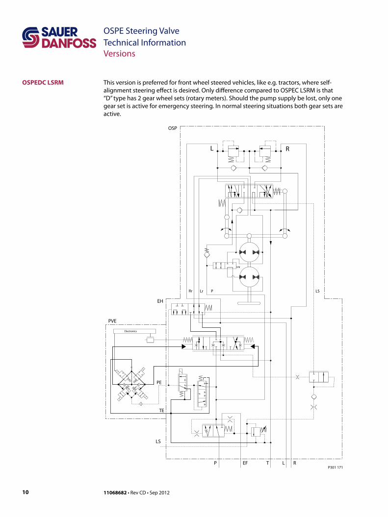
OSPEDC LSRM This version is preferred for front wheel steered vehicles, like e.g. tractors, where self-alignment steering effect is desired. Only difference compared to OSPEC LSRM is that “D” type has 2 gear wheel sets (rotary meters). Should the pump supply be lost, only one gear set is active for emergency steering. In normal steering situations both gear sets are active.
P
LS
TE
T L R
EH
PVE
Electronics
OSP
L R
LS
PE
EF
Rr Lr P
P301 171

1111068682 • Rev CD • Sep 2012
OSPE Steering Valve Technical InformationVersions
OSPEDF LS This version is preferred for rear wheel steered and articulated vehicles. Only difference compared to OSPEF LS is that “D” type has 2 gear wheel sets (rotary meters). This version however is shown without priority valve.
P
LS
TE
T L R
EH
PVE
Electronics
OSP
L R
LS
PE
P
P301 172

12 11068682 • Rev CD • Sep 2012
OSPE Steering ValveTechnical InformationSteering Valve EHPS and Electrical Actuation PVE for EHPS
PVED-CL OSPE with an electrical programmable module (PVED-CL) the following steering features in electro hydraulic steer mode/field mode are possible:
• GPS-steering• Row sensor/ camera steering• Joy stick or mini st. wheel steering• Variable steering ratio• Speed depending steering ratio
This block diagram shows all input devices possible for the PVED-CL actuator/controller.Detailed description is to be found in seperate literature, PVED-CL User Manual, please contact Sauer-Danfoss Sales Organization.
MMIDisplay, Buttons e.g. to select program, Display Info, Status,
Diagnostic CAN
Vehicle speed signal(J1939 CAN) Feedback Sensor
Analogue or CAN
Redundant FeedbackAnalogue or CAN
Steering Wheel Sensor
(SASA) CAN
Control principle:Closed loop
PVED-CL
High Priority Steering Device
e.g. joystick Analogue or CAN
Low Priority Steering Device
e.g. joystick Analogue or CAN
Control principle:Open loop
Control principle:Closed loop
Control principle:Open loop
Control principle:Closed loop
Control principle:Open loop
Control principle:Closed loop
Vehicle Speed Dependent Sensitivity
Actuator Dependent Sensitivity
Anti-Drift(knob position control)
Soft End Stop
Anti Jerk Fixed Ramps, Times
Anti Jerk Speed Dependent Times
Vehicle SpeedDependent Sensitivity
Actuator Dependent Sensitivity
Soft End Stop
Anti Jerk Fixed Ramps
Anti Jerk Speed Dependent Times
Vehicle Speed Dependent Sensitivity
Actuator Dependent Sensitivity
Soft End Stop
Anti Jerk Fixed Ramps
Anti Jerk Speed Dependent Times
Vehicle Speed Dependent Sensitivity
High Priority Set-point Controller (GPS)
ISO11798 CAN
P301 022

1311068682 • Rev CD • Sep 2012
OSPE Steering Valve Technical InformationFunction
OSPE Steering Valve The OSPE includes the following main components
18
8
14, 15, 17
16
7
21
2
1
9, 10, 11
13
12
22
3
5
P301 216
Designation of OSPE elementsItem Description1 Shock valves2 Suction valves3 Spool/sleeve set5 Gear set
7Mode select and EH cut off valve
8 EH directional valve9 PVE control unit10 LVDT transducer11 Solenoid valve bridge
12Control valve for mode select
13Pilot reduction valve, 12 bar
14 PP damping orifice15 Priority valve spool16 Priority valve spring17 Dynamic orifice18 Pilot pressure relief valve21 PVFC valve/LS resolver
22Neutral spring package for spool/sleeve

14 11068682 • Rev CD • Sep 2012
OSPE Steering ValveTechnical InformationFunction
OSPEC LSRM
Designation of OSPE elementsItem Description1 Shock valves2 Suction valves3 Spool/sleeve set
4Emergency steering check valve
5 Gear set6 P-check valve
7Mode select and EH cut off valve
8 EH directional valve9 PVE control unit10 LVDT transducer11 Solenoid valve bridge
12Control valve for mode select
13Pilot reduction valve, 12 bar
14 PP damping orifi ce15 Priority valve spool16 Priority valve spring17 Dynamic orifi ce18 Pilot pressure relief valve19 LS orifi ce20 LS check valve21 PVFC valve/LS resolver
22Neutral spring package for spool/sleeve
T301 008E
P
LS
TE
T L R
EH
PVE
Electronics
LS
EF
2
1
3
4
5
6
7
8
9
10
11
12 13
14 15 16 17 18
21
20
19
22
OSP
L R
CF
PE
Rr Lr P
P301 173
Neutral position
1511068682 • Rev CD • Sep 2012
OSPE Steering Valve Technical InformationFunction
OSPEC LSRMNeutral position
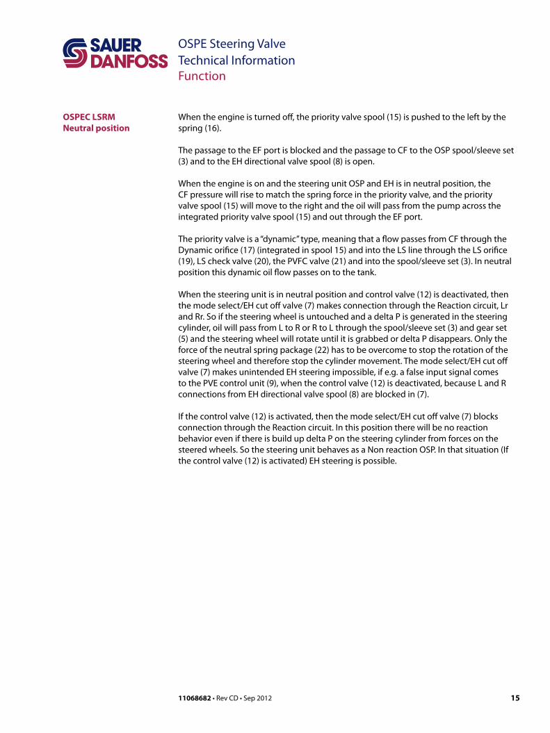
When the engine is turned off, the priority valve spool (15) is pushed to the left by the spring (16).
The passage to the EF port is blocked and the passage to CF to the OSP spool/sleeve set (3) and to the EH directional valve spool (8) is open.
When the engine is on and the steering unit OSP and EH is in neutral position, the CF pressure will rise to match the spring force in the priority valve, and the priority valve spool (15) will move to the right and the oil will pass from the pump across the integrated priority valve spool (15) and out through the EF port.
The priority valve is a “dynamic” type, meaning that a flow passes from CF through the Dynamic orifice (17) (integrated in spool 15) and into the LS line through the LS orifice (19), LS check valve (20), the PVFC valve (21) and into the spool/sleeve set (3). In neutral position this dynamic oil flow passes on to the tank.
When the steering unit is in neutral position and control valve (12) is deactivated, then the mode select/EH cut off valve (7) makes connection through the Reaction circuit, Lr and Rr. So if the steering wheel is untouched and a delta P is generated in the steering cylinder, oil will pass from L to R or R to L through the spool/sleeve set (3) and gear set (5) and the steering wheel will rotate until it is grabbed or delta P disappears. Only the force of the neutral spring package (22) has to be overcome to stop the rotation of the steering wheel and therefore stop the cylinder movement. The mode select/EH cut off valve (7) makes unintended EH steering impossible, if e.g. a false input signal comes to the PVE control unit (9), when the control valve (12) is deactivated, because L and R connections from EH directional valve spool (8) are blocked in (7).
If the control valve (12) is activated, then the mode select/EH cut off valve (7) blocks connection through the Reaction circuit. In this position there will be no reaction behavior even if there is build up delta P on the steering cylinder from forces on the steered wheels. So the steering unit behaves as a Non reaction OSP. In that situation (If the control valve (12) is activated) EH steering is possible.

16 11068682 • Rev CD • Sep 2012
OSPE Steering ValveTechnical InformationFunction
OSPEC LSRM
Designation of OSPE elementsItem Description1 Shock valves2 Suction valves3 Spool/sleeve set
4Emergency steering check valve
5 Gear set6 P-check valve
7Mode select and EH cut off valve
8 EH directional valve9 PVE control unit10 LVDT transducer11 Solenoid valve bridge
12Control valve for mode select
13Pilot reduction valve, 12 bar
14 PP damping orifi ce15 Priority valve spool16 Priority valve spring17 Dynamic orifi ce18 Pilot pressure relief valve19 LS orifi ce20 LS check valve21 PVFC valve/LS resolver
22Neutral spring package for spool/sleeve
T301 008E
Steering right with steering wheel
P
LS
TE
T L R
EH
PVE
Electronics
OSP
L R
LS
2
1
3
4
5
6
7
8
9
10
11
12 13
14 15
21
20
19
22
EF
16 17 18
CF
PE
Rr Lr P
P301 174
1711068682 • Rev CD • Sep 2012
OSPE Steering Valve Technical InformationFunction
OSPEC LSRMSteering Right with Steering Wheel
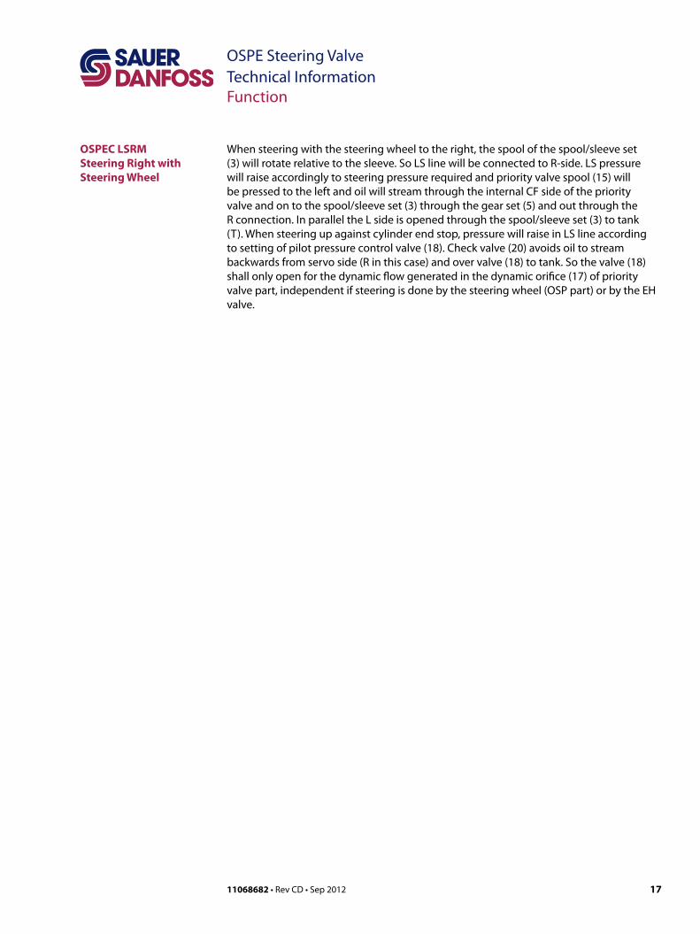
When steering with the steering wheel to the right, the spool of the spool/sleeve set (3) will rotate relative to the sleeve. So LS line will be connected to R-side. LS pressure will raise accordingly to steering pressure required and priority valve spool (15) will be pressed to the left and oil will stream through the internal CF side of the priority valve and on to the spool/sleeve set (3) through the gear set (5) and out through the R connection. In parallel the L side is opened through the spool/sleeve set (3) to tank (T). When steering up against cylinder end stop, pressure will raise in LS line according to setting of pilot pressure control valve (18). Check valve (20) avoids oil to stream backwards from servo side (R in this case) and over valve (18) to tank. So the valve (18) shall only open for the dynamic flow generated in the dynamic orifice (17) of priority valve part, independent if steering is done by the steering wheel (OSP part) or by the EH valve.

18 11068682 • Rev CD • Sep 2012
OSPE Steering ValveTechnical InformationFunction
P
PE
LS
TE
T L R
EH
PVE
Electronics
LS
EF
2
1
3
4
5
6
7
8
9
10
11
12 13
14 15 16 17 18
21
20
19
22
OSP
L R
CF
Rr Lr P
P301 175
OSPEC LSRM
Designation of OSPE elementsItem Description1 Shock valves2 Suction valves3 Spool/sleeve set
4Emergency steering check valve
5 Gear set6 P-check valve
7Mode select and EH cut off valve
8 EH directional valve9 PVE control unit10 LVDT transducer11 Solenoid valve bridge
12Control valve for mode select
13Pilot reduction valve, 12 bar
14 PP damping orifi ce15 Priority valve spool16 Priority valve spring17 Dynamic orifi ce18 Pilot pressure relief valve19 LS orifi ce20 LS check valve21 PVFC valve/LS resolver
22Neutral spring package for spool/sleeve
T301 008E
Steering Right with EH
1911068682 • Rev CD • Sep 2012
OSPE Steering Valve Technical InformationFunction
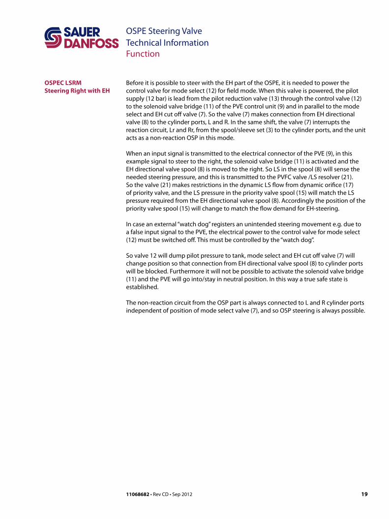
OSPEC LSRMSteering Right with EH
Before it is possible to steer with the EH part of the OSPE, it is needed to power the control valve for mode select (12) for field mode. When this valve is powered, the pilot supply (12 bar) is lead from the pilot reduction valve (13) through the control valve (12) to the solenoid valve bridge (11) of the PVE control unit (9) and in parallel to the mode select and EH cut off valve (7). So the valve (7) makes connection from EH directional valve (8) to the cylinder ports, L and R. In the same shift, the valve (7) interrupts the reaction circuit, Lr and Rr, from the spool/sleeve set (3) to the cylinder ports, and the unit acts as a non-reaction OSP in this mode.
When an input signal is transmitted to the electrical connector of the PVE (9), in this example signal to steer to the right, the solenoid valve bridge (11) is activated and the EH directional valve spool (8) is moved to the right. So LS in the spool (8) will sense the needed steering pressure, and this is transmitted to the PVFC valve /LS resolver (21). So the valve (21) makes restrictions in the dynamic LS flow from dynamic orifice (17) of priority valve, and the LS pressure in the priority valve spool (15) will match the LS pressure required from the EH directional valve spool (8). Accordingly the position of the priority valve spool (15) will change to match the flow demand for EH-steering.
In case an external “watch dog” registers an unintended steering movement e.g. due to a false input signal to the PVE, the electrical power to the control valve for mode select (12) must be switched off. This must be controlled by the “watch dog”.
So valve 12 will dump pilot pressure to tank, mode select and EH cut off valve (7) will change position so that connection from EH directional valve spool (8) to cylinder ports will be blocked. Furthermore it will not be possible to activate the solenoid valve bridge (11) and the PVE will go into/stay in neutral position. In this way a true safe state is established.
The non-reaction circuit from the OSP part is always connected to L and R cylinder ports independent of position of mode select valve (7), and so OSP steering is always possible.

20 11068682 • Rev CD • Sep 2012
OSPE Steering ValveTechnical InformationFunction
PVES and PVED-CL, electrical actuationThe philosophy of Sauer-Danfoss electro hydraulic actuation, type PVE, is integration of electronics, sensors and actuators into a single unit that interfaces directly to the OSPE steering valve body.
Closed loop controlAll the proportional actuators feature an integrated feedback transducer that measures spool movement in relation to the input signal, and by means of a solenoid valve bridge, controls the direction, velocity and position of the directional spool of the valve. The integrated electronics compensate for flow forces on the spool, internal leakage, changes in oil viscosity, pilot pressure, etc. This results in lower hysteresis and better resolution. Furthermore the electronics enable built in safety like fault monitoring, directional indication and LED light indication.
PrincipleIn principle the input signal (set-point signal) determines the level of pilot pressurewhich moves the main spool. The position of the directional spool is sensed in the LVDT transducer which generates an electric feed-back signal registred by the electronics. The variation between the set-point signal and feed-back signal actuates the solenoid valves. The solenoid valves are actuated so that hydraulic pilot pressure drives the directional spool into the correct position.
Inductive transducer, LVDT(Linear Variable Differential Trnasformer). When the directional spool is moved, a voltage is induced proportional to the spool position. The use of LVDT gives contact-free monitoring of the directional spool position. This means an extra-long working life and no limitation as regards the type of hydraulic fluid used. In addition, LVDT gives precise position signal of high resolution.
Integrated pulse width modulationPositioning of the directional spool in PVES is based on the pulse width modulation principle. As soon as the directional spool reaches the required position, modulation stops and the spool is locked in position.
2111068682 • Rev CD • Sep 2012
OSPE Steering Valve Technical InformationTechnical Data
OSPE
Weights
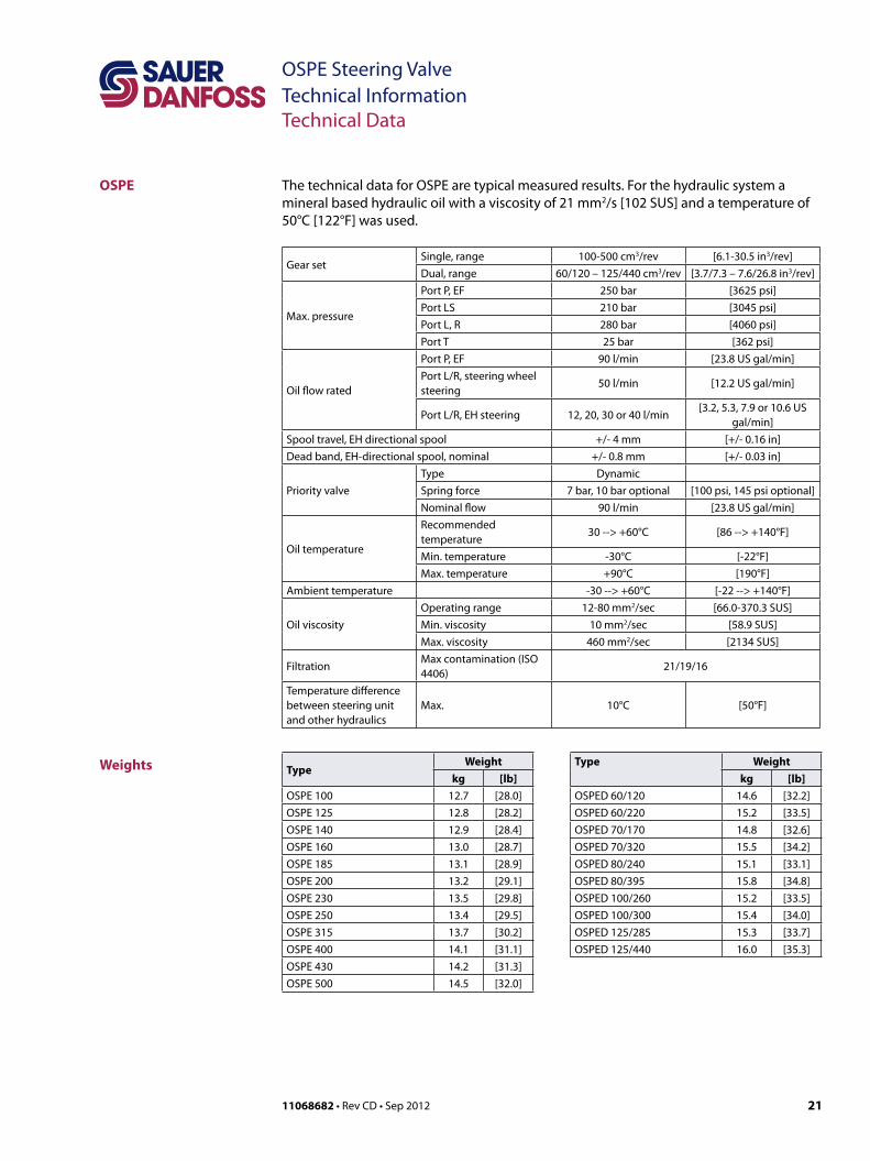
The technical data for OSPE are typical measured results. For the hydraulic system a mineral based hydraulic oil with a viscosity of 21 mm2/s [102 SUS] and a temperature of 50°C [122°F] was used.
Gear setSingle, range 100-500 cm3/rev [6.1-30.5 in3/rev]Dual, range 60/120 – 125/440 cm3/rev [3.7/7.3 – 7.6/26.8 in3/rev]
Max. pressure
Port P, EF 250 bar [3625 psi]Port LS 210 bar [3045 psi]Port L, R 280 bar [4060 psi]Port T 25 bar [362 psi]
Oil flow rated
Port P, EF 90 l/min [23.8 US gal/min]Port L/R, steering wheel steering
50 l/min [12.2 US gal/min]
Port L/R, EH steering 12, 20, 30 or 40 l/min[3.2, 5.3, 7.9 or 10.6 US
gal/min]Spool travel, EH directional spool +/- 4 mm [+/- 0.16 in]Dead band, EH-directional spool, nominal +/- 0.8 mm [+/- 0.03 in]
Priority valveType DynamicSpring force 7 bar, 10 bar optional [100 psi, 145 psi optional]Nominal flow 90 l/min [23.8 US gal/min]
Oil temperature
Recommended temperature
30 --> +60°C [86 --> +140°F]
Min. temperature -30°C [-22°F]Max. temperature +90°C [190°F]
Ambient temperature -30 --> +60°C [-22 --> +140°F]
Oil viscosityOperating range 12-80 mm2/sec [66.0-370.3 SUS]Min. viscosity 10 mm2/sec [58.9 SUS]Max. viscosity 460 mm2/sec [2134 SUS]
FiltrationMax contamination (ISO 4406)
21/19/16
Temperature difference between steering unit and other hydraulics
Max. 10°C [50°F]
TypeWeight
kg [lb]OSPE 100 12.7 [28.0]OSPE 125 12.8 [28.2]OSPE 140 12.9 [28.4]OSPE 160 13.0 [28.7]OSPE 185 13.1 [28.9]OSPE 200 13.2 [29.1]OSPE 230 13.5 [29.8]OSPE 250 13.4 [29.5]OSPE 315 13.7 [30.2]OSPE 400 14.1 [31.1]OSPE 430 14.2 [31.3]OSPE 500 14.5 [32.0]
Type Weightkg [lb]
OSPED 60/120 14.6 [32.2]OSPED 60/220 15.2 [33.5]OSPED 70/170 14.8 [32.6]OSPED 70/320 15.5 [34.2]OSPED 80/240 15.1 [33.1]OSPED 80/395 15.8 [34.8]OSPED 100/260 15.2 [33.5]OSPED 100/300 15.4 [34.0]OSPED 125/285 15.3 [33.7]OSPED 125/440 16.0 [35.3]
22 11068682 • Rev CD • Sep 2012
OSPE Steering ValveTechnical InformationTechnical Data
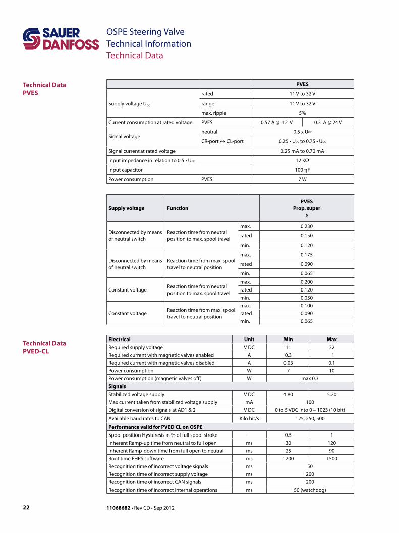
PVES
Supply voltage UDC
rated 11 V to 32 V
range 11 V to 32 V
max. ripple 5%
Current consumption at rated voltage PVES 0.57 A @ 12 V 0.3 A @ 24 V
Signal voltageneutral 0.5 x UDC
CR-port ↔CL-port 0.25 • UDC to 0.75 • UDC
Signal current at rated voltage 0.25 mA to 0.70 mA
Input impedance in relation to 0.5 • UDC 12 KΩ
Input capacitor 100 ηF
Power consumption PVES 7 W
Supply voltage FunctionPVES
Prop. supers
Disconnected by meansof neutral switch
Reaction time from neutralposition to max. spool travel
max. 0.230
rated 0.150
min. 0.120
Disconnected by meansof neutral switch
Reaction time from max. spool travel to neutral position
max. 0.175
rated 0.090
min. 0.065
Constant voltageReaction time from neutral position to max. spool travel
max. 0.200rated 0.120min. 0.050
Constant voltageReaction time from max. spool travel to neutral position
max. 0.100rated 0.090min. 0.065
Electrical Unit Min MaxRequired supply voltage V DC 11 32Required current with magnetic valves enabled A 0.3 1Required current with magnetic valves disabled A 0.03 0.1Power consumption W 7 10Power consumption (magnetic valves off) W max 0.3SignalsStabilized voltage supply V DC 4.80 5.20Max current taken from stabilized voltage supply mA 100Digital conversion of signals at AD1 & 2 V DC 0 to 5 VDC into 0 – 1023 (10 bit)
Available baud rates to CAN Kilo bit/s 125, 250, 500
Performance valid for PVED CL on OSPESpool position Hysteresis in % of full spool stroke - 0.5 1Inherent Ramp-up time from neutral to full open ms 30 120Inherent Ramp-down time from full open to neutral ms 25 90Boot time EHPS software ms 1200 1500Recognition time of incorrect voltage signals ms 50Recognition time of incorrect supply voltage ms 200Recognition time of incorrect CAN signals ms 200Recognition time of incorrect internal operations ms 50 (watchdog)
Technical Data PVED-CL
Technical Data PVES

2311068682 • Rev CD • Sep 2012
OSPE Steering Valve Technical InformationTechnical Data
Hysteresis, PVES and PVED-CL1) rated ∼0%1) Hysteresis is indicated at rated voltage and f = 0.02 Hz for one cycle (one cycle = neutral ->full CL -> full CR -> neutral.
Hysteresis, PVES and PVED-CL
157-669.11
Spool Travel
Technical Data PVES and PVED-CL
Oil viscosity
Oil viscosity
range 12 - 75 mm2/s [65 - 347 SUS]
min. 4 mm2/s [39 SUS]
max. 460 mm2/s [2128 SUS]
Note: Max. start up viscosity 2500 mm2/s
Oil temperature
Oil-temperature
Rec. range 30 - 60˚C [86 -140˚F]
min. -30˚C [-22˚F]
max. 90˚C [194˚F]
Filtering
Filtering in the hydraulic system
Max. allowed degree of contamination (ISO 4406, 1999 version): 23/19/16
Oil consumptionSupply voltage
FunctionPVES
and PVED-CL
Without voltage
Pilot oil flow per
PVE
0.3 l/min
neutral[0.078 US gal/min]
With voltage
Pilot oil flow per PVE
locked0.1 l/min
[0.026 US gal/min]
continuous actuations
0.8 l/min
[0.211 US gal/min]
Ambient temperatureAmbiant temperatur range Rec.
-30° →+60°C [-22° → +140°F]
Enclosure and connectorVersion with AMP JPT connector
Grade of enclosure * IP 66
In particulary exposed applications, protection in the form of screening is recommended.
Pilot pressure
Pilot pressure (relative to T pressure)
nom. 13.5 bar [196 psi]
min. 10 bar [145 psi]
max. 15 bar [217 psi]
* According to the international standard IEC 529
24 11068682 • Rev CD • Sep 2012
OSPE Steering ValveTechnical InformationTechnical Data
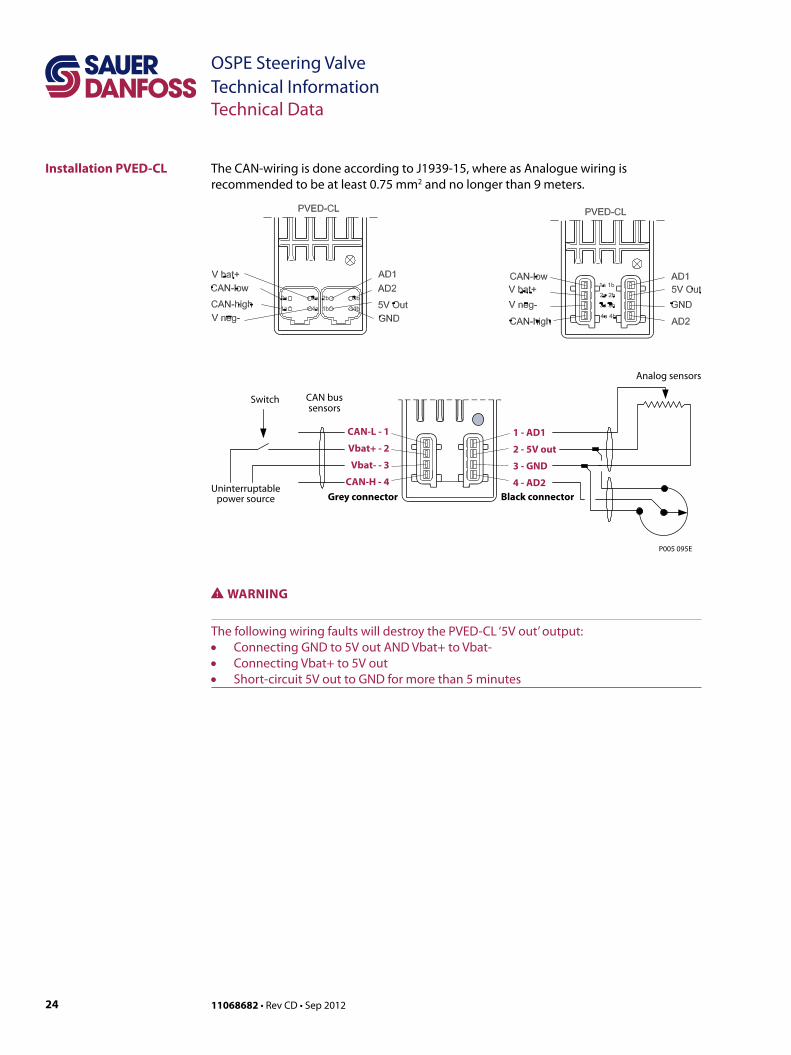
The CAN-wiring is done according to J1939-15, where as Analogue wiring is recommended to be at least 0.75 mm2 and no longer than 9 meters.
Installation PVED-CL
1 - AD1
2 - 5V out
3 - GND
4 - AD2
Analog sensors
CAN bussensors
Switch
P005 095E
Uninterruptablepower source Black connectorGrey connector
CAN-L - 1
Vbat+ - 2
Vbat- - 3
CAN-H - 4
WWARNING
The following wiring faults will destroy the PVED-CL ‘5V out’ output: • Connecting GND to 5V out AND Vbat+ to Vbat- • Connecting Vbat+ to 5V out • Short-circuit 5V out to GND for more than 5 minutes

2511068682 • Rev CD • Sep 2012
OSPE Steering Valve Technical InformationTechnical Data
Technical Data, Coil of Control Valve for Mode Select
Specifications
Electrical Specifications
Terminals
• Duty cycle rating: 100%• Magnet wire insulation: Class H (180C)• Ambient temperature: -30 to 60 °C
[-22 to 140 °F]• Diodes are available; contact your
Sauer-Danfoss representative.• Environmental protection: IP65• Input voltage tolerance: ±10%• All AC coils are internally rectified
16 watt coilsVoltage (V) Resistance (Ohms) ±5% @ 20 °C [72 °F] Current draw (A) at 25 °C [77 °F] Color
12 VDC 9 1.33 Grey
Amp Junior Timer Code AJ
Deutsch Code DE
Part numberVoltage (V) Power (W) Part number12 VDC 16 D08-16-12D-AJ
Part numberVoltage (V) Power (W) Part number12 VDC 16 D08-16-12D-DE
P103 948E
Maximumoperating limit
Minimumpull-in
voltage
D08 16 watt coil
Am
bien
tTem
pera
ture
(deg
C )
1009080706050
3040
2010
0-10-20
Percent Rated Voltage70% 80% 90% 100% 110% 120% 130% 140%
60.7[2.39]
45.2[1.78]
P102 538
56.6[2.23]
P102 541
26 11068682 • Rev CD • Sep 2012
OSPE Steering ValveTechnical InformationDimensioning
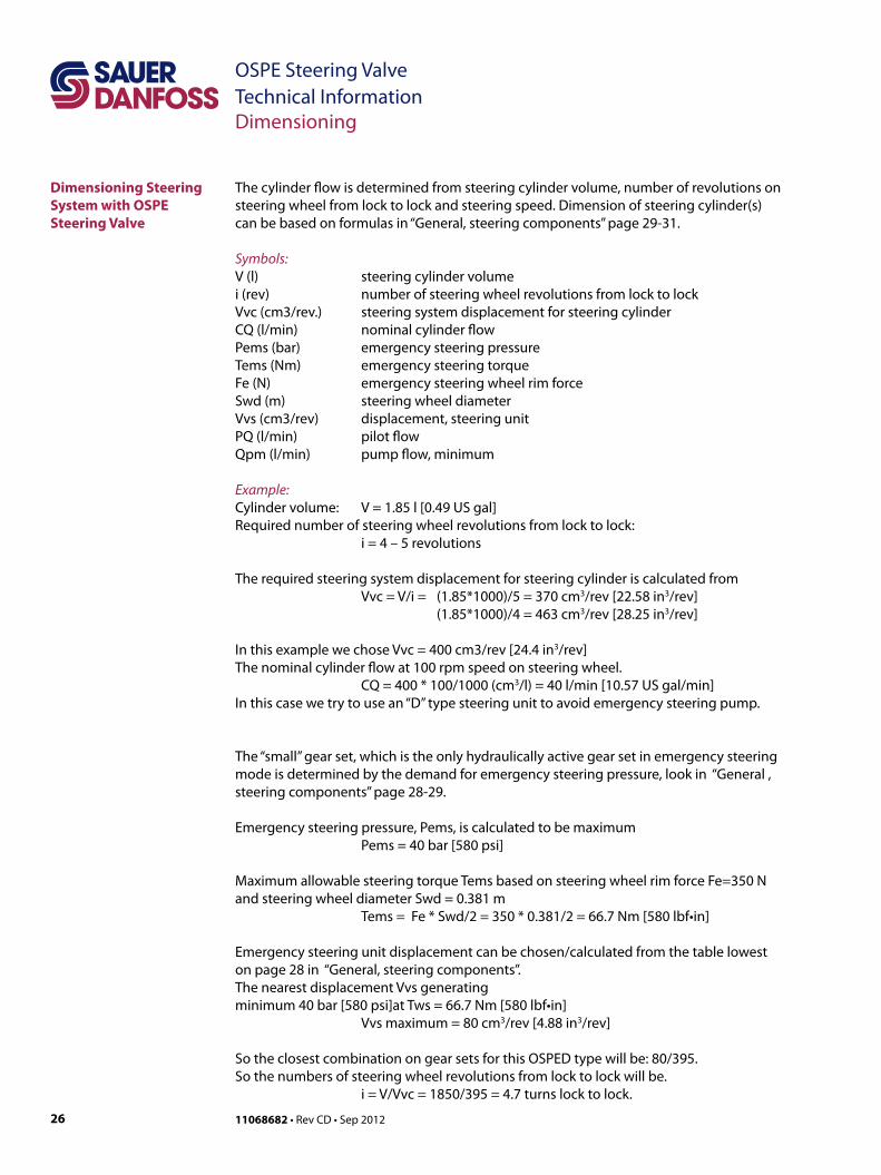
Dimensioning Steering System with OSPE Steering Valve
The cylinder flow is determined from steering cylinder volume, number of revolutions on steering wheel from lock to lock and steering speed. Dimension of steering cylinder(s) can be based on formulas in “General, steering components” page 29-31.
Symbols:V (l) steering cylinder volumei (rev) number of steering wheel revolutions from lock to lockVvc (cm3/rev.) steering system displacement for steering cylinderCQ (l/min) nominal cylinder flowPems (bar) emergency steering pressureTems (Nm) emergency steering torqueFe (N) emergency steering wheel rim forceSwd (m) steering wheel diameterVvs (cm3/rev) displacement, steering unitPQ (l/min) pilot flowQpm (l/min) pump flow, minimum
Example:Cylinder volume: V = 1.85 l [0.49 US gal]Required number of steering wheel revolutions from lock to lock: i = 4 – 5 revolutions
The required steering system displacement for steering cylinder is calculated from Vvc = V/i = (1.85*1000)/5 = 370 cm3/rev [22.58 in3/rev] (1.85*1000)/4 = 463 cm3/rev [28.25 in3/rev]
In this example we chose Vvc = 400 cm3/rev [24.4 in3/rev]The nominal cylinder flow at 100 rpm speed on steering wheel. CQ = 400 * 100/1000 (cm3/l) = 40 l/min [10.57 US gal/min]In this case we try to use an “D” type steering unit to avoid emergency steering pump.
The “small” gear set, which is the only hydraulically active gear set in emergency steering mode is determined by the demand for emergency steering pressure, look in “General , steering components” page 28-29.
Emergency steering pressure, Pems, is calculated to be maximum Pems = 40 bar [580 psi]
Maximum allowable steering torque Tems based on steering wheel rim force Fe=350 N and steering wheel diameter Swd = 0.381 m Tems = Fe * Swd/2 = 350 * 0.381/2 = 66.7 Nm [580 lbf•in]
Emergency steering unit displacement can be chosen/calculated from the table lowest on page 28 in “General, steering components”.The nearest displacement Vvs generating minimum 40 bar [580 psi]at Tws = 66.7 Nm [580 lbf•in] Vvs maximum = 80 cm3/rev [4.88 in3/rev]
So the closest combination on gear sets for this OSPED type will be: 80/395.So the numbers of steering wheel revolutions from lock to lock will be. i = V/Vvc = 1850/395 = 4.7 turns lock to lock.

2711068682 • Rev CD • Sep 2012
OSPE Steering Valve Technical InformationTechnical Characteristics
Cylinder flow characteristic for directional spools
A = valid for spools for nominal cylinder flow CQ = 12 l/min [3.17 US gal/min]B = valid for spools for nominal cylinder flow CQ = 20 l/min [5.28 US gal/min]C = valid for spools for nominal cylinder flow CQ = 30 l/min [7.97 US gal/min]D = valid for spools for nominal cylinder flow CQ = 40 l/min [10.57 US gal/min]
The curves are valid for OSPE with internal priority valve w. 7 bar [100 psi] spring and 1.0 mm [0.039 in] dynamic orifice and @ 60 l/min [15.85 US gal/min] pump flow.For OSPE without internal priority valve, the curves are valid in combination with external priority valve OLS 80, 152B8269 @ 60 l/min [15.85 US gal/min] pump flow.
EH-Directional Spools of OSPE
B
C
A
D
B
C
A
D
L R-4 -3 -2 -1 0 1 2 3 4 mm
0.5 0.650.35 Us/UDC0.540.460.430.40 0.57 0.60
-580 0 Can164-164-328-492 328 492 580
5
10
15
20
25
30
35
40
45l/min
10
7.5
5
2.5
US gal/min
Q
P301 220

28 11068682 • Rev CD • Sep 2012
OSPE Steering ValveTechnical InformationTechnical Characteristics
Pilot pressure relief valve: (P - T, Qp) characteristic
The pilot pressure relief valve protects the steering system against excessive pressure. The pilot pressure relief valve works together with the priority valve in the OSPE to limit the maximum steering pressure P-T. The pilot pressure relief valve is set at an oil flow to the priority valve of 25 l/min [6.6 US gal/min]. Setting tolerance: rated value +10 bar [145 psi].P-T P-T
barpsi
3500
3000
2500
2000
1500
1000
500
0 10 20 30 40 50 60 70 80 90 l/min
140 bar[2030 psi]
170 bar[2465 psi]
200 bar[2900 psi]
250
200
150
100
50
0Qp
US gal/minQp
0 5 10 15 20
V301 217
2911068682 • Rev CD • Sep 2012
OSPE Steering Valve Technical Information
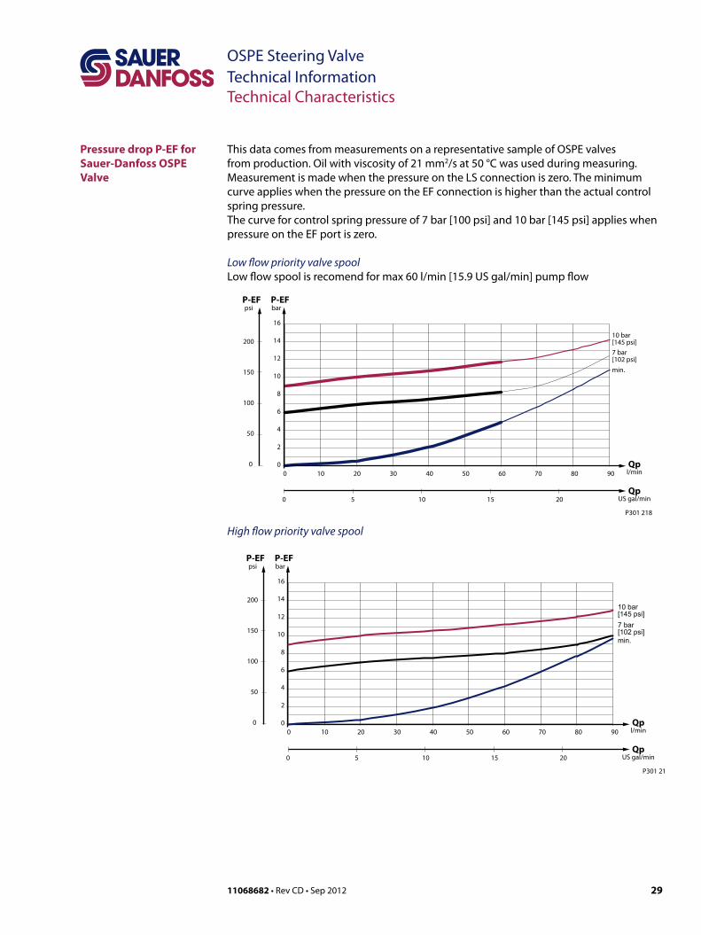
Pressure drop P-EF for Sauer-Danfoss OSPE Valve
This data comes from measurements on a representative sample of OSPE valves from production. Oil with viscosity of 21 mm2/s at 50 °C was used during measuring. Measurement is made when the pressure on the LS connection is zero. The minimum curve applies when the pressure on the EF connection is higher than the actual control spring pressure. The curve for control spring pressure of 7 bar [100 psi] and 10 bar [145 psi] applies when pressure on the EF port is zero.
Low flow priority valve spoolLow flow spool is recomend for max 60 l/min [15.9 US gal/min] pump flow
High flow priority valve spool
P-EFP-EFbar
0
2
4
6
8
10
12
14
16
0 10 20 30 40 50 60 70 80 90
min.
7 bar[102 psi]
10 bar[145 psi]
P301 218
psi
Qpl/min
QpUS gal/min
200
150
100
50
0
0 5 10 15 20
P-EFP-EFbar
0
2
4
6
8
10
12
14
16
0 10 20 30 40 50 60 70 80 90
P301 219
psi
Qpl/min
QpUS gal/min
200
150
100
50
0
0 5 10 15 20
min.
7 bar[102 psi]
10 bar[145 psi]
Technical Characteristics
30 11068682 • Rev CD • Sep 2012
OSPE Steering ValveTechnical InformationNotes
Notes
3111068682 • Rev CD • Sep 2012
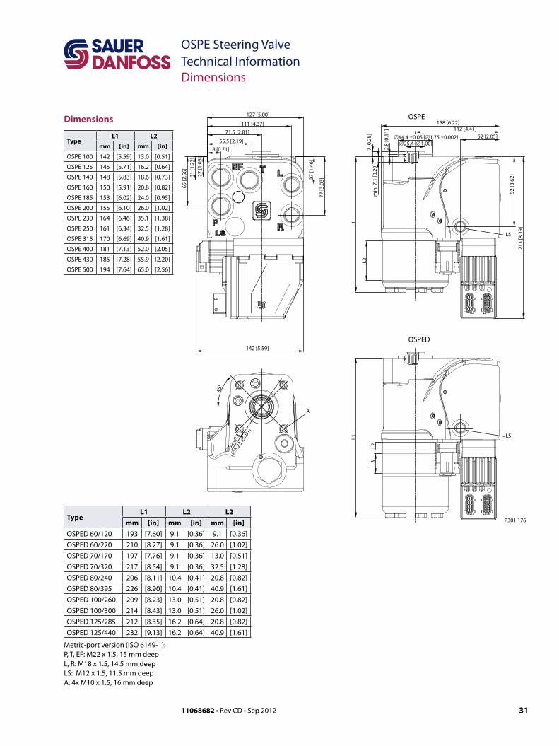
OSPE Steering Valve Technical InformationDimensions
TypeL1 L2
mm [in] mm [in]
OSPE 100 142 [5.59] 13.0 [0.51]
OSPE 125 145 [5.71] 16.2 [0.64]
OSPE 140 148 [5.83] 18.6 [0.73]
OSPE 160 150 [5.91] 20.8 [0.82]
OSPE 185 153 [6.02] 24.0 [0.95]
OSPE 200 155 [6.10] 26.0 [1.02]
OSPE 230 164 [6.46] 35.1 [1.38]
OSPE 250 161 [6.34] 32.5 [1.28]
OSPE 315 170 [6.69] 40.9 [1.61]
OSPE 400 181 [7.13] 52.0 [2.05]
OSPE 430 185 [7.28] 55.9 [2.20]
OSPE 500 194 [7.64] 65.0 [2.56]
37 [1
.46]
∅25.4 [∅1.00]∅44.4 ±0.05 [∅1.75 ±0.002]
2.8
[0.1
1]
92 [3
.62]
A
∅82
±0.3
45°
142 [5.59]
18 [0.71]55.5 [2.19]
71.5 [2.81]111 [4.37]
77 [3
.03]
LS
L2
213
[8.3
9]
158 [6.22]
52 [2.05]112 [4.41]
L1
min
. 7.1
[0.2
9]7
[0.2
8]
27 [1
.06]
31 [1
.22]
65 [2
.56]
LSL1
L2L3
OSPED
OSPE
[∅3.2
3 ±0.0
1]
127 [5.00]
P301 176TypeL1 L2 L2
mm [in] mm [in] mm [in]OSPED 60/120 193 [7.60] 9.1 [0.36] 9.1 [0.36]OSPED 60/220 210 [8.27] 9.1 [0.36] 26.0 [1.02]OSPED 70/170 197 [7.76] 9.1 [0.36] 13.0 [0.51]OSPED 70/320 217 [8.54] 9.1 [0.36] 32.5 [1.28]OSPED 80/240 206 [8.11] 10.4 [0.41] 20.8 [0.82]OSPED 80/395 226 [8.90] 10.4 [0.41] 40.9 [1.61]OSPED 100/260 209 [8.23] 13.0 [0.51] 20.8 [0.82]OSPED 100/300 214 [8.43] 13.0 [0.51] 26.0 [1.02]OSPED 125/285 212 [8.35] 16.2 [0.64] 20.8 [0.82]OSPED 125/440 232 [9.13] 16.2 [0.64] 40.9 [1.61]
Metric-port version (ISO 6149-1):P, T, EF: M22 x 1.5, 15 mm deepL, R: M18 x 1.5, 14.5 mm deepLS: M12 x 1.5, 11.5 mm deepA: 4x M10 x 1.5, 16 mm deep
Dimensions

32 11068682 • Rev CD • Sep 2012
OSPE Steering ValveTechnical InformationHydraulic Systems
OSPE in a system with fixed gear pump and GPS steeringThe pump, the OSPE priority valve part and the working hydraulics must be protected by a separate pressure relief valve.The vehicle controller/watch dog monitors input from the GPS, steering angle sensor (SASA) and signal from steering cylinder sensor. In case of unintended movement from the cylinder sensor, the watch dog shall remove power to the control valve for mode select/pilot dump, and in this way electro hydraulic actuation of steering cylinder is made impossible. The system turns into true safe mode.
P
LS
TE
T L R
EH
PVE
Electronics
OSP
L R
LS
PE
EF
Working HydraulicPrime
mover
SASA
GPS
Watchdogcontroller
Display
OC
Rr Lr P
P301 177
Hydraulic Systems

3311068682 • Rev CD • Sep 2012
OSPE Steering Valve Technical InformationHydraulic Systems
P
LS
TE
T L R
EH
PVE
Electronics
OSP
L R
LS
PE
EF
Working HydraulicPrime
mover
SASA
GPS
Watchdogcontroller
Display
CC
AUX
Rr Lr P
P301 178
Hydraulic Systems (continued)
OSPE in a system with variable pump and GPS steeringThe pump must have a built in pilot pressure relief valve to protect the OSPE, the priority valve part, the working hydraulics and the AUX function. AUX can be a brake system, which must have limited oil consumption to ensure steering capability in any case. Alternative pressure protection must be present in working and in AUX-hydraulic.

34 11068682 • Rev CD • Sep 2012
OSPE Steering ValveTechnical InformationSystem Safety
The steering unit part of the OSPE acts like any other OSP steering units in case of no pump supply.In such case the gear wheel set acts as a hand driven pump, and so muscular power will be converted from input torque and rotation on the steering wheel to hydraulic power in the form of pressure and flow out of the cylinder port to which side the steering is done. See page 26 in this catalog and page 28 in “General, steering components” for calculating manual/emergency steering.
Please see promotional brochure 11059881 for further information.
Emergency Steering
Fault monitoringA fault monitoring system is provided in all PVES and PVED-CL modules. The system is available as passive fault monitoring type, which provides a warning signal only. • Passive fault monitoring systems are triggered by three main events:
1. Input signal monitoringThe PVES input signal voltage is continuously monitored. The permissible range is between 15% and 85% of the supply voltage. Outside this range the section will switch into an active error state.
2. Transducer supervisionIf one of the wires to the LVDT sensor is broken or short-circuited, the section will switch into an active error state.
3. Supervision of the closed loopThe actual position must always correspond to the demanded position (input signal). If the actual spool position is further than the demanded spool position (>12%, ), the system detects an error and will switch into an active error state. On the other hand, a situation where the actual position is closer to neutral than that demanded will not cause an error state. This situation is considered “in control”.When an active error state occurs, the fault monitoring logic will be triggered:
Passive fault monitoring • A delay of 250 ms before anything happens. • The solenoid valve bridge will not be disabled but still control the main spool
position.• An alarm signal is sent out through the appropriate pin connection, no. 3.• This state is not memorized. When the erroneous state disappears, the alarm signal
will turn to passive again. However, the signal will always be active for a minimum of 100 ms when triggered.
OSPE and system safety, PVES and PVED CL
3511068682 • Rev CD • Sep 2012
OSPE Steering Valve Technical InformationSystem Safety
System Safety(continued)
Safety Considerations
3. Internal clockThe solenoid valves are disabled when the internal clock frequency fails, and the main
spool will return/stay in neutral.
On-road Operation
WWARNINGThe PVES or PVED-CL shall be de-energized while driving on-road. It is the OEMs responsibility to establish the necessary means to inform and de-energize the PVE from the cabin when driving on public roads.
WWARNING
The Sauer-Danfoss range of PVE actuators are single string designs with limited on board fault monitoring. Sauer-Danfoss strongly recommends application of vehicle specific safety monitoring systems that will detect non-conforming steering and effectively disable electro-hydraulic actuators or issue appropriate warnings as the case may be. A minimum safety system should include a manual power switch to electrical power off electro-hydraulic actuators while driving on public roads.
For details, see:- Technical information, PVE Series 4- User Manual PVED-CL controller for Electro-Hydraulics Steeringor contact Sauer-Danfoss Technical Support Team
To prevent the electronics from going into an undefined state, a general supervision of the power supply and the internal clock frequency is made. This function applies to PVES and PVED-CL and will not activate fault monitoring:1. High supply voltage
The solenoid valves are disabled when the supply voltage exceeds 36 V, and the main spool will return/stay in neutral.
2. Low supply voltage: The solenoid valves are disabled when the supply voltage falls below 8.5 V, and the main spool will return/stay in neutral.

36 11068682 • Rev CD • Sep 2012
OSPE Steering ValveTechnical InformationOrder Specification
Variants and Order SpecificationSpecification table for Sauer-Danfoss OSPE steering valve. Part Variants
OSP
Gear set, cm3/rev Single 100, 125, 140, 160, 185, 200, 230, 250, 315, 400, 430, 500
Dual, ”D”-type
60/120, 60/185, 60/200, 60/220, 60/260, 60/29070/140, 70/170, 70/195, 70/230, 70/270, 70/320, 70/385
80/160, 80/205, 80/240, 80/280, 80/395100/200, 100/260, 100/300, 100/415
125/250, 125/325, 125/440
Spool/sleeve“C”-dynamic, LSRM, Load Sensing, Reaction“F”-dynamic, LS, Non-Reaction
Actuation moduleType PVES PVED CC PVED CLConnection AMP (A) Deutsch (D)
Coil for control valve/pilot dump Connection AMP (A) Deutsch (D)EH-directional spool Cylinder flow, l/min 12 20 30 40
Priority valveWith spool, nominal flow, l/min 60 90Spring force, bar 7 10With out spool No EF port present. P-flow determined by steering demand only
Housing 1) Thread MetricRelief valve Bar 100 - 210Shock valves Bar 160 - 260
1) Housing, threads: P, T & EF L & R LS
Metric, ISO 6149-1 M 22 x 1.5 – O* + S** M 18 x 1.5 – O* + S** M 12 x 1.5 – O* + S**
O*: O-ring chamfer on port connectionS**: Spot face around port connection
OSPEF w. displacement < 250 cc/rev. and integrated priority valve not to be used! By experience we know the combination OSPEF with displacement < 250 cc/rev. and integrated priority may cause oscillations in steering system. Therefore do not specify such combinations. We recommend using OSPEC when displacement is smaller than 250 cc and if integrated priority valve is needed.
3711068682 • Rev CD • Sep 2012
OSPE Steering Valve Technical InformationOrder Specification
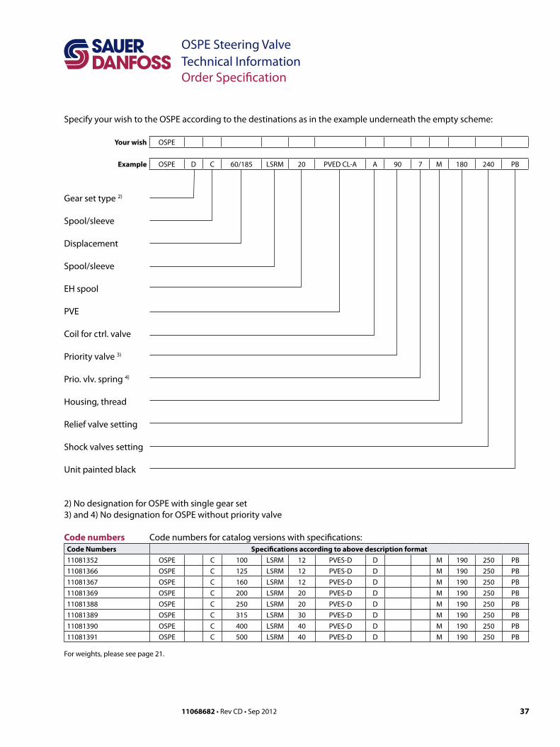
Specify your wish to the OSPE according to the destinations as in the example underneath the empty scheme:
Your wish OSPE
Example OSPE D C 60/185 LSRM 20 PVED CL-A A 90 7 M 180 240 PB
Gear set type 2)
Spool/sleeve
Displacement
Spool/sleeve
EH spool
PVE
Coil for ctrl. valve
Priority valve 3)
Prio. vlv. spring 4)
Housing, thread
Relief valve setting
Shock valves setting
Unit painted black
2) No designation for OSPE with single gear set3) and 4) No designation for OSPE without priority valve
Code numbers for catalog versions with specifications:Code Numbers Specifications according to above description format11081352 OSPE C 100 LSRM 12 PVES-D D M 190 250 PB11081366 OSPE C 125 LSRM 12 PVES-D D M 190 250 PB11081367 OSPE C 160 LSRM 12 PVES-D D M 190 250 PB11081369 OSPE C 200 LSRM 20 PVES-D D M 190 250 PB11081388 OSPE C 250 LSRM 20 PVES-D D M 190 250 PB11081389 OSPE C 315 LSRM 30 PVES-D D M 190 250 PB11081390 OSPE C 400 LSRM 40 PVES-D D M 190 250 PB11081391 OSPE C 500 LSRM 40 PVES-D D M 190 250 PB
For weights, please see page 21.
Code numbers
38 11068682 • Rev CD • Sep 2012
OSPE Steering ValveTechnical InformationSensor Type SASA
Sensor Type SASA General
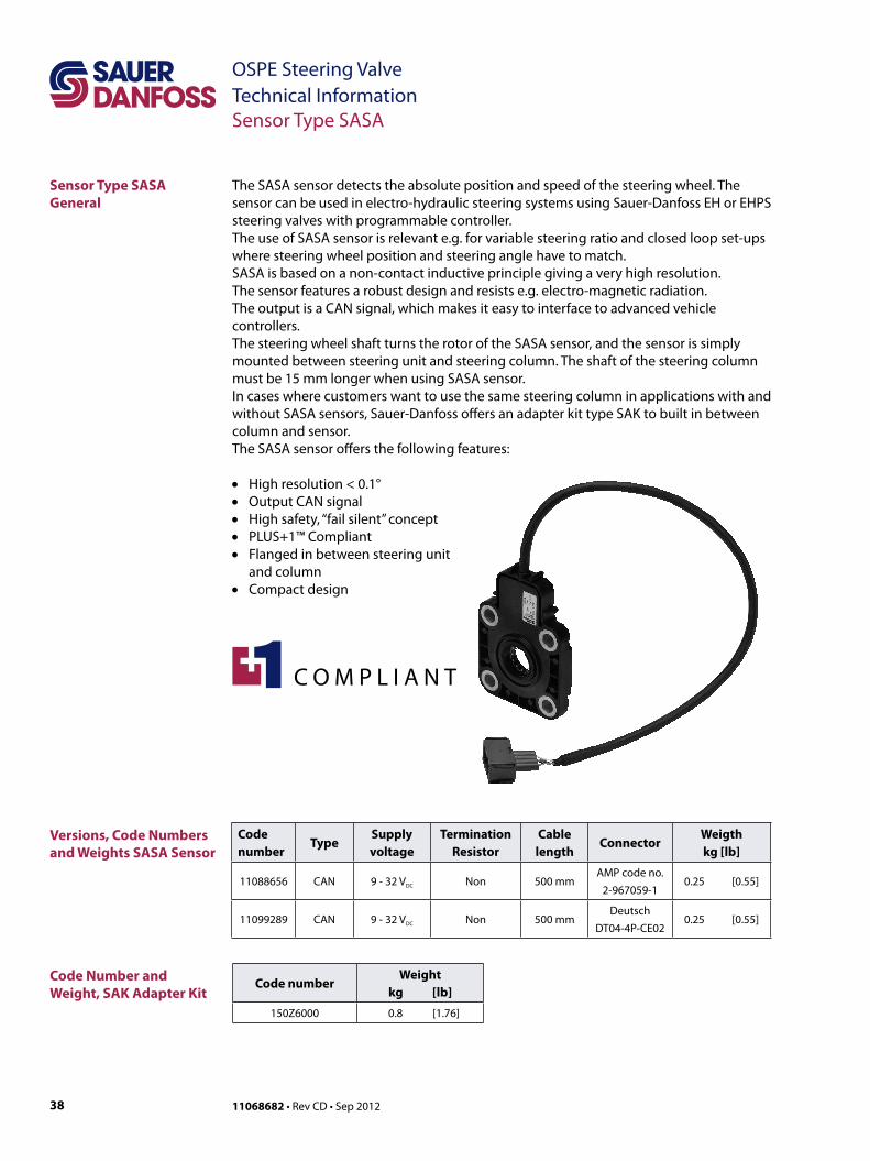
Versions, Code Numbers and Weights SASA Sensor
Code Number and Weight, SAK Adapter Kit
Code number
TypeSupply voltage
Termination Resistor
Cable length
ConnectorWeigthkg [lb]
11088656 CAN 9 - 32 VDC Non 500 mmAMP code no.
2-967059-10.25 [0.55]
11099289 CAN 9 - 32 VDC Non 500 mmDeutsch
DT04-4P-CE020.25 [0.55]
Code numberWeight
kg [lb]
150Z6000 0.8 [1.76]
The SASA sensor detects the absolute position and speed of the steering wheel. The sensor can be used in electro-hydraulic steering systems using Sauer-Danfoss EH or EHPS steering valves with programmable controller.The use of SASA sensor is relevant e.g. for variable steering ratio and closed loop set-ups where steering wheel position and steering angle have to match.SASA is based on a non-contact inductive principle giving a very high resolution. The sensor features a robust design and resists e.g. electro-magnetic radiation. The output is a CAN signal, which makes it easy to interface to advanced vehicle controllers.The steering wheel shaft turns the rotor of the SASA sensor, and the sensor is simply mounted between steering unit and steering column. The shaft of the steering column must be 15 mm longer when using SASA sensor.In cases where customers want to use the same steering column in applications with and without SASA sensors, Sauer-Danfoss offers an adapter kit type SAK to built in between column and sensor. The SASA sensor offers the following features:
• High resolution < 0.1°• Output CAN signal• High safety, “fail silent” concept• PLUS+1™ Compliant• Flanged in between steering unit
and column• Compact design
3911068682 • Rev CD • Sep 2012
OSPE Steering Valve Technical InformationSensor Type SASA
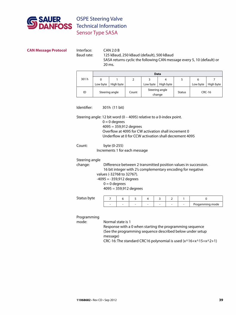
CAN Message Protocol Interface: CAN 2.0 BBaud rate: 125 kBaud, 250 kBaud (default), 500 kBaud SASA returns cyclic the following CAN message every 5, 10 (default) or 20 ms.
301 h
Data
0Low byte
1High byte
2 3Low byte
4High byte
5 6Low byte
7High byte
ID Steering angle CountSteering angle
changeStatus CRC-16
Identifier: 301h (11 bit)
Steering angle: 12 bit word (0 – 4095) relative to a 0-index point. 0 = 0 degrees 4095 = 359,912 degrees Overflow at 4095 for CW activation shall increment 0 Underflow at 0 for CCW activation shall decrement 4095
Count: byte (0-255) Increments 1 for each message
Steering angle change: Difference between 2 transmitted position values in succession. 16 bit integer with 2’s complementary encoding for negative
values (-32768 to 32767). -4095 = -359,912 degrees 0 = 0 degrees 4095 = 359,912 degrees
Programmingmode: Normal state is 1 Response with a 0 when starting the programming sequence (See the programming sequence described below under setup message) CRC-16: The standard CRC16 polynomial is used (x^16+x^15+x^2+1)
7 6 5 4 3 2 1 0
- - - - - - - Progamming mode
Status byte
40 11068682 • Rev CD • Sep 2012
OSPE Steering ValveTechnical InformationSensor Type SASA
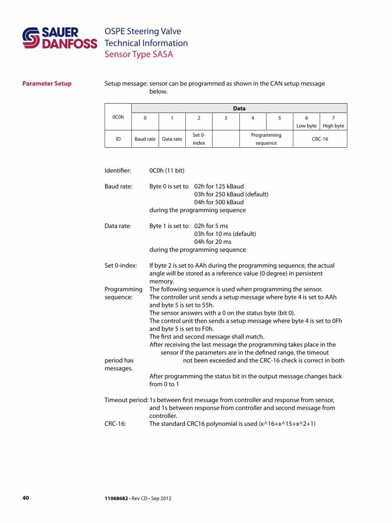
Parameter Setup Setup message: sensor can be programmed as shown in the CAN setup message below.
0C0h
Data
0 1 2 3 4 5 6Low byte
7High byte
ID Baud rate Data rateSet 0- index
Programmingsequence
CRC-16
Identifier: 0C0h (11 bit)
Baud rate: Byte 0 is set to 02h for 125 kBaud 03h for 250 kBaud (default) 04h for 500 kBaud during the programming sequence
Data rate: Byte 1 is set to 02h for 5 ms 03h for 10 ms (default) 04h for 20 ms during the programming sequence
Set 0-index: If byte 2 is set to AAh during the programming sequence, the actual angle will be stored as a reference value (0 degree) in persistent memory.Programming The following sequence is used when programming the sensor.sequence: The controller unit sends a setup message where byte 4 is set to AAh and byte 5 is set to 55h. The sensor answers with a 0 on the status byte (bit 0). The control unit then sends a setup message where byte 4 is set to 0Fh and byte 5 is set to F0h. The first and second message shall match. After receiving the last message the programming takes place in the sensor if the parameters are in the defined range, the timeout period has not been exceeded and the CRC-16 check is correct in both messages. After programming the status bit in the output message changes back from 0 to 1
Timeout period: 1s between first message from controller and response from sensor, and 1s between response from controller and second message from controller.CRC-16: The standard CRC16 polynomial is used (x^16+x^15+x^2+1)
4111068682 • Rev CD • Sep 2012
OSPE Steering Valve Technical InformationSensor Type SASA
Technical Data Mechanical Input range: Continuous 360° rotationRotor torque: ≤ 0.2 NmExpected life: > 10 million cycles
ElectricalSupply voltage: 9 - 32 VDCPower consumption: <1 W
OutputCAN V2.0B, (compatible to J1939)
Termination resistor: 120 ohm (optional)Baud rate: 125, 250 or 500 kb/sAngle: 12-bit word (0 - 4095) relative to a programmable 0-index point.Resolution: < 0.1°Linearity: ±1.0%Angle change: 16 bit integer with 2’s complementary encoding for negative values (-32768 to 32767).
Safety functionIf a failure occurs the CAN-bus will “fail silent” (The CAN-bus driver will be disabled).
EnvironmentalOperating temperature: -30° to 85°C [-22 to 185°F]Storage temperature: -40° to 105°CSealing: IP65EMI/RFI Rating: 100 V/mVibration: Meets IEC 60068-2-64Shock: Meets IEC 60068-2-27 test Ea
42 11068682 • Rev CD • Sep 2012
OSPE Steering ValveTechnical InformationSensor Type SASA
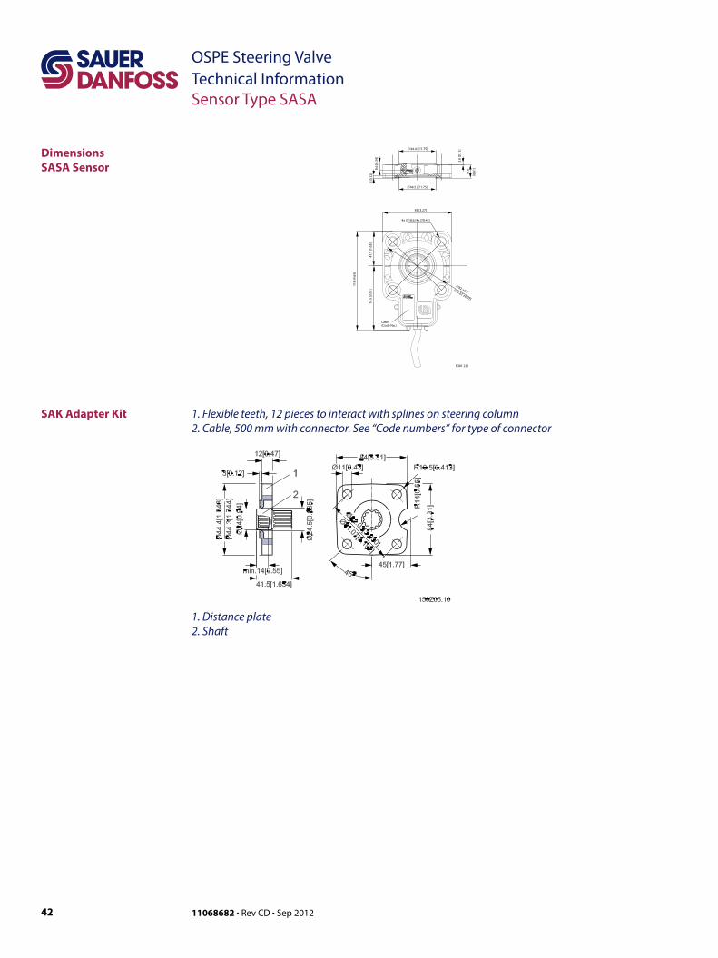
DimensionsSASA Sensor
SAK Adapter Kit
∅44.5 [∅1.75]
4x ∅10.6 [4x ∅0.42]
∅82 ±0.3[∅3.23 ±0.01]
∅44.4 [∅1.75]
83 [3.27]
41.5
[1.6
3]
118
[4.6
5]
76.5
[3.0
1]
Label (Code No.)
3 [0
.12] 15
.6
[0.6
1]8.6
[0.3
4]
2.8
[0.1
1]
P301 221
1. Flexible teeth, 12 pieces to interact with splines on steering column2. Cable, 500 mm with connector. See “Code numbers” for type of connector
1. Distance plate2. Shaft

4311068682 • Rev CD • Sep 2012
OSPE Steering Valve Technical InformationSensor Type SASA
Installation SASA has to be mounted between steering column and steering unit (OSP) with 4 boltsmax 30 N•m [265.5 lbf•in]. Shaft in column must be 15 mm [0.59 in] longer when using SASA.
Assembly: SASA sensor and OSP steering unit
1. SASA sensor2, OSP steering unit
Caution!
Make sure that the spline profile of the SASA sensor is aligned to the spline profile of the steering column shaft. A safe method of assembly is to place SASA sensor on the steering column spline shaft first – and not opposite! In case of using force, there is a risk of bending the spline profile of SASA sensor.
For use of original steering column, use adapter kit type SAK, see sketch below.Assembly: SAK adapter kit, SASA sensor and OSP steering unit
1. Shaft of SAK adapter kit2. Distance plate of SAK adapter kit3. SASA sensor4. OSP steering unit 27.5
[1.08]
4321
4 [0.16]
min. 7.1 [0.28]
P301 222
min. 22.4 [0.88]17 [0.67]
15.3[0.60]
1 2
4 [0.16]
P301 223

44 11068682 • Rev CD • Sep 2012
OSPE Steering ValveTechnical InformationSensor Type SASA
Installation (continued)
Electric connection through cable mounted with an AMP Connector.
AMP type 2-967059-1Pin 1 CAN-LowPin 2 +supply voltagePin 3 GndPin 4 CAN-High
Mating connector assemblyAMP type 2-965261-1JPT contacts 2-962915-1Wire sealing 828904-1
Recommended wiring practice• Protect all wires from mechanical abuse.• Use a wire gauge that is appropriate for the sensor electrical mating connector.• Use wire with abrasion resistant insulation.• Separate high current wires such as feeds to solenoids, lights, alternators, or fuel
pumps from control wires. Recommended minimum separation is 300 mm [11.8 in].• Run wires along the inside of or close to metal machine frame surfaces where
possible. This simulates a shield which minimizes the effects of EMI/RFI radiation.• Do not run wires near sharp metal corners. Run wires through grommets when
rounding a corner.• Provide strain relief for all wires.• Avoid running wires near moving or vibrating components.• Avoid long, unsupported wire spans.• All sensors have dedicated wired power sources and ground returns. They should be
used.• Twist sensor lines about one turn every 100 mm [3.94 in].• Use wire harness anchors that will allow wires to float with respect to the machine
frame rather than rigid anchors.

4511068682 • Rev CD • Sep 2012
OSPE Steering Valve Technical InformationNotes
Notes

46 11068682 • Rev CD • Sep 2012
OSPE Steering ValveTechnical InformationNotes
Notes
4711068682 • Rev CD • Sep 2012
OSPE Steering Valve Technical InformationNotes
Notes
Local address:
Sauer-Danfoss GmbH & Co. OHGPostfach 2460, D-24531 NeumünsterKrokamp 35, D-24539 Neumünster, GermanyPhone: +49 4321 871 0Fax: +49 4321 871 122
Sauer-Danfoss ApSDK-6430 Nordborg, DenmarkPhone: +45 7488 4444Fax: +45 7488 4400
Sauer-Danfoss is a global manufacturer and supplier of high-quality hydraulic and electronic components. We specialize in providing state-of-the-art technology and solutions that excel in the harsh operating conditions of the mobile o -highway market. Building on our extensive applications expertise, we work closely with our customers to ensure exceptional performance for a broad range of o -highway vehicles.
We help OEMs around the world speed up system development, reduce costs and bring vehicles to market faster. Sauer-Danfoss – Your Strongest Partner in Mobile Hydraulics.
Go to www.sauer-danfoss.com for further product information.
Wherever o -highway vehicles are at work, so is Sauer-Danfoss.
We o er expert worldwide support for our customers, ensuring the best possible solutions for outstanding performance. And with an extensive network of Global Service Partners, we also provide comprehensive global service for all of our components.
Please contact the Sauer-Danfoss representative nearest you.
Products we o er:
• Bent Axis Motors
• Closed Circuit Axial Piston Pumps and Motors
• Displays
• Electrohydraulic Power Steering
• Electrohydraulics
• Hydraulic Power Steering
• Integrated Systems
• Joysticks and Control Handles
• Microcontrollers and Software
• Open Circuit Axial Piston Pumps
• Orbital Motors
• PLUS+1™ GUIDE
• Proportional Valves
• Sensors
• Steering
• Transit Mixer Drives
Members of the Sauer-Danfoss Group:
Comatrolwww.comatrol.com
Schwarzmüller-Inverterwww.schwarzmueller-inverter.com
Turolla www.turollaocg.com
Valmovawww.valmova.com
Hydro-Gear www.hydro-gear.com
Sauer-Danfoss-Daikinwww.sauer-danfoss-daikin.com
Sauer-Danfoss (US) Company2800 East 13th StreetAmes, IA 50010, USAPhone: +1 515 239 6000Fax: +1 515 239 6618
Sauer-Danfoss-Daikin LTD.Shin-Osaka TERASAKI 3rd Bldg. 6F1-5-28 Nishimiyahara, Yodogawa-kuOsaka 532-0004, JapanPhone: +81 6 6395 6066Fax: +81 6 6395 8585
w w w . s a u e r - d a n f o s s . c o m11068682 • Rev CD • Sep 2012