Embed Size (px)
Citation preview
powersolutions.danfoss.com
ensures that your next steering system meets the latest standards
Safetycompliance
Rapid response – complete control OSPE electrohydraulic steering units
powersolutions.danfoss.com
Today’s vehicles require versatile solutions that increase productivity, reduce operator fatigue and provide a safe, comfortable working environment. Our new OSPE steering unit introduces a range of innovative features that not only improve vehicle performance and operator comfort, but also facilitate compliance with the safety demands of Machinery Directive 2006/42/EC. With selectable reactive and non-reactive steering modes, a ‘safe state’ option, variable steering ratio, and Load Sensing and Open Center options, all integrated in a single, compact steering unit, you can offer your customers the flexible solutions they demand. OSPE – meeting the demands of safety and performance.
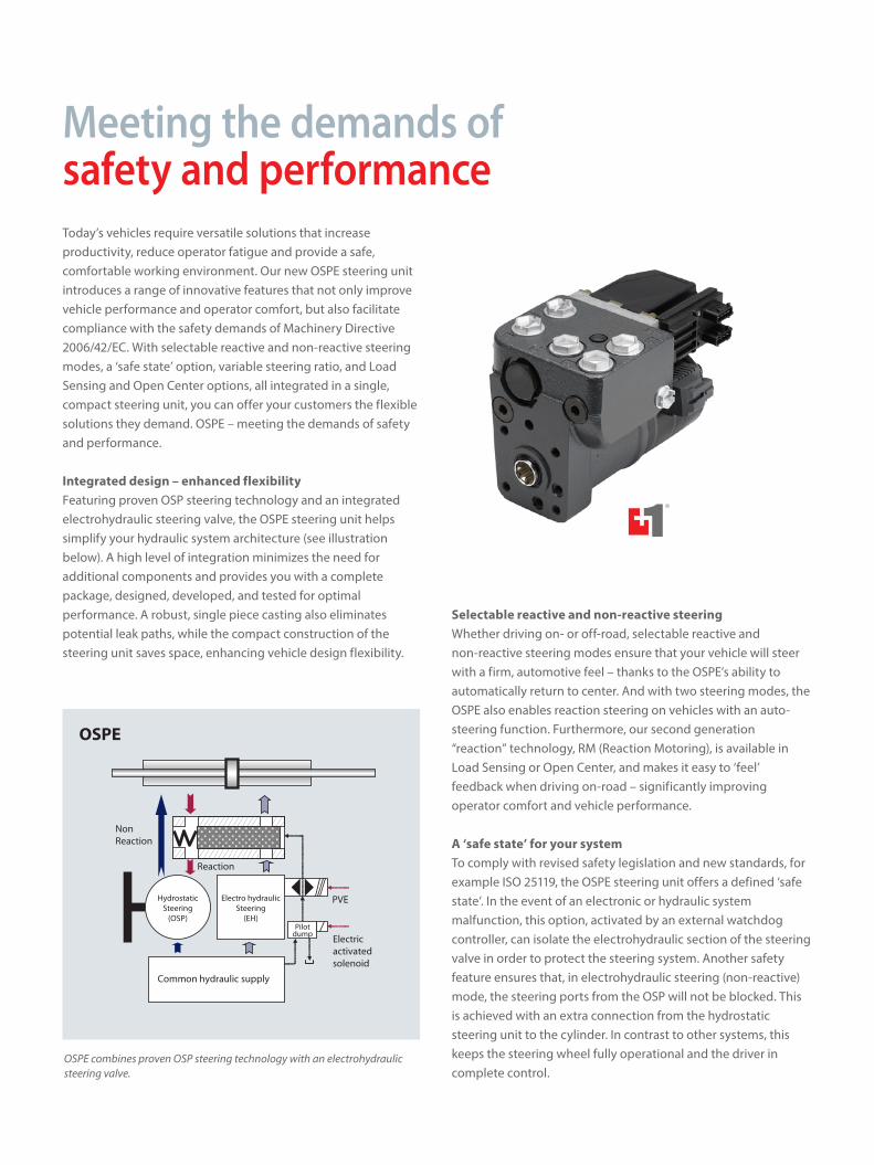
Integrated design – enhanced flexibilityFeaturing proven OSP steering technology and an integrated electrohydraulic steering valve, the OSPE steering unit helps simplify your hydraulic system architecture (see illustration below). A high level of integration minimizes the need for additional components and provides you with a complete package, designed, developed, and tested for optimal performance. A robust, single piece casting also eliminates potential leak paths, while the compact construction of the steering unit saves space, enhancing vehicle design flexibility.
Selectable reactive and non-reactive steeringWhether driving on- or off-road, selectable reactive and non-reactive steering modes ensure that your vehicle will steer with a firm, automotive feel – thanks to the OSPE’s ability to automatically return to center. And with two steering modes, the OSPE also enables reaction steering on vehicles with an auto-steering function. Furthermore, our second generation “reaction” technology, RM (Reaction Motoring), is available in Load Sensing or Open Center, and makes it easy to ‘feel’ feedback when driving on-road – significantly improving operator comfort and vehicle performance.
A ‘safe state’ for your system To comply with revised safety legislation and new standards, for example ISO 25119, the OSPE steering unit offers a defined ‘safe state’. In the event of an electronic or hydraulic system malfunction, this option, activated by an external watchdog controller, can isolate the electrohydraulic section of the steering valve in order to protect the steering system. Another safety feature ensures that, in electrohydraulic steering (non-reactive) mode, the steering ports from the OSP will not be blocked. This is achieved with an extra connection from the hydrostatic steering unit to the cylinder. In contrast to other systems, this keeps the steering wheel fully operational and the driver in complete control.
Meeting the demands of safety and performance
OSPE combines proven OSP steering technology with an electrohydraulic steering valve.
HydrostaticSteering
(OSP)
Common hydraulic supply
Electro hydraulicSteering
(EH)Pilot
dump
Non Reaction
PVE
Reaction
Electric activatedsolenoid
OSPE
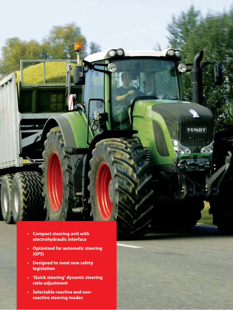
• Compact steering unit with electrohydraulic interface
• Optimized for automatic steering (GPS)
• Designed to meet new safety legislation
• ‘Quick steering’ dynamic steering ratio adjustment
• Selectable reactive and non-reactive steering modes
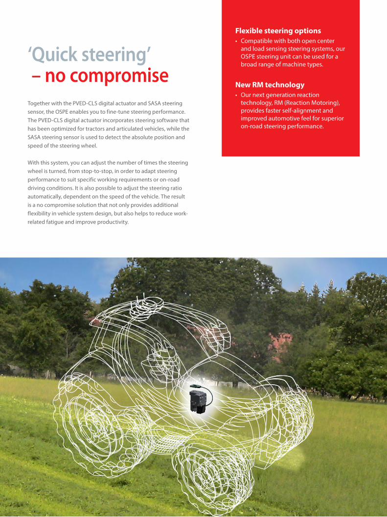
‘Quick steering’ – no compromiseTogether with the PVED-CLS digital actuator and SASA steering sensor, the OSPE enables you to fine-tune steering performance. The PVED-CLS digital actuator incorporates steering software that has been optimized for tractors and articulated vehicles, while the SASA steering sensor is used to detect the absolute position and speed of the steering wheel. With this system, you can adjust the number of times the steering wheel is turned, from stop-to-stop, in order to adapt steering performance to suit specific working requirements or on-road driving conditions. It is also possible to adjust the steering ratio automatically, dependent on the speed of the vehicle. The result is a no compromise solution that not only provides additional flexibility in vehicle system design, but also helps to reduce work-related fatigue and improve productivity.
Flexible steering options• Compatible with both open center
and load sensing steering systems, our OSPE steering unit can be used for a broad range of machine types.
New RM technology• Our next generation reaction
technology, RM (Reaction Motoring), provides faster self-alignment and improved automotive feel for superior on-road steering performance.
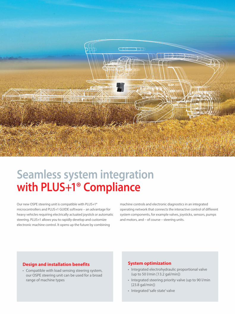
Seamless system integration with PLUS+1® ComplianceOur new OSPE steering unit is compatible with PLUS+1® microcontrollers and PLUS+1 GUIDE software – an advantage for heavy vehicles requiring electrically actuated joystick or automatic steering. PLUS+1 allows you to rapidly develop and customize electronic machine control. It opens up the future by combining
machine controls and electronic diagnostics in an integrated operating network that connects the interactive control of different system components, for example valves, joysticks, sensors, pumps and motors, and – of course – steering units.
System optimization• Integrated electrohydraulic proportional valve
(up to 50 l/min [13.2 gal/min])• Integrated steering priority valve (up to 90 l/min
[23.8 gal/min])• Integrated ‘safe state’ valve
Design and installation benefits• Compatible with load sensing steering system,
our OSPE steering unit can be used for a broad range of machine types

Anticipating changes to system design and qualification, we have developed the OSPE steering unit to meet new safety regulations.
Recent European safety legislation has revised Machinery Directive 2006/42/EC and applies to all vehicles built in or shipped to Europe after December 29, 2009. This revision means that our OEM customers must perform and document a hazard and risk analysis for all vehicle functions according to, for example, ISO 13849 or ISO 25119. Anticipating these changes, the OSPE steering unit has been designed to comply with this new legislation and provide the basis for a ‘safe state’ system architecture – for example, Category 2 or 3 (ISO 25119). As a result, OEMs can speed up steering system development and certification, reduce costs, and bring vehicles to market faster.
Ready to meet new safety regulations
The hazard and risk analysis process starts by identifying the main functions of the vehicle. Each system is then defined and possible hazards identified.
Overview of the hazard and risk analysis process
Rear hitch operation
Rear implement
Front implement
Front loader operation
Front hitch operation
Suspension
Braking
Propel
1
OEM benefits• Safety features designed to meet new
legislation
• Easier system homologation reduces development costs
• Faster steering certification shortens time to market
Steering• Auto-steering
• Quick steering (variable ratio)
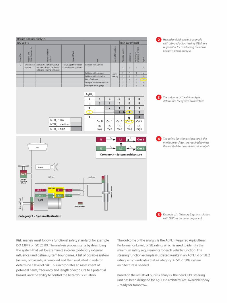
Risk analysis must follow a functional safety standard, for example, ISO 13849 or ISO 25119. The analysis process starts by describing the system that will be examined, in order to identify external influences and define system boundaries. A list of possible system failures, or hazards, is compiled and then evaluated in order to determine a level of risk. This incorporates an assessment of potential harm, frequency and length of exposure to a potential hazard, and the ability to control the hazardous situation.
The outcome of the analysis is the AgPLr (Required Agricultural Performance Level), or SIL rating, which is used to identify the minimum safety requirements for each vehicle function. The steering function example illustrated results in an AgPLr: d or SIL 2 rating, which indicates that a Category 3 (ISO 25119), system architecture is needed.
Based on the results of our risk analysis, the new OSPE steering unit has been designed for AgPLr: d architectures. Available today – ready for tomorrow.
Display
PVED CLS
SASA
OSPE
Stee
ring
Whe
el
Stee
ring
Cyl
inde
r
AnalogueCAN bus
GPS
Vehicle Speed
Electric Steering
Wheel
AUX
L1
L2
Out 1
Out 2
I1
I2
Category 3 – System illustration
I1S1 L1 S1 Out 1
I2S2 L2
S2 Out 2
Category 3 – System architecture
Hazard and risk analysisISO 25119 Risk parameters
Haz
ard
No:
Haz
ards
and
H
azar
dous
eve
nts:
Poss
ible
haz
ard
ca
uses
:
Haz
ard
Effec
t
Risk
Mod
e of
Ope
ratio
n
Pote
ntia
l har
m S
Expo
sure
E
Poss
ibili
ty o
f av
oida
nce
of h
arm
AgPL
r
H2 Unintended steering
Malfunction of valve, actua-tor, input device, hardware, software, external influence
- Driving path deviation- loss of steering control
Collision with vehicle
Auto-steering
2 2 3 b
Collision with persons 3 1 2 a
Collision with obstacles 2 2 3 b
Risk of roll over 2 4 3 d
Injury of bystander (service) 3 2 3 c
Falling off a cliff, gorge 3 1 3 b
AgPL1
a 1 B B B B
b 2 1 B B B
c 2 1 1 1
d 2 2 2
e 3
Cat B
DC low
Cat 1
DC med
Cat 2
DC med
Cat 3
DC med
Cat 4
DC high
MTTFd = low
MTTFd = medium
MTTFd = high
Hazard and risk analysis example with off-road auto-steering. OEMs are responsible for conducting their own hazard and risk analysis.
2
The outcome of the risk analysis determines the system architecture.
3
The safety function architecture is the minimum architecture required to meet the result of the hazard and risk analysis.
4
Example of a Category 3 system solution with OSPE as the core component.
5
Danfoss can accept no responsibility for possible errors in catalogues, brochures and other printed material. Danfoss reserves the right to alter its products without notice. This also applies to products already on order provided that such alterations can be made without changes being necessary in specifications already agreed.All trademarks in this material are property of the respective companies. Danfoss and the Danfoss logotype are trademarks of Danfoss A/S. All rights reserved.
About Danfoss Power Solutions
Danfoss Power Solutions is a global manufacturer and supplier of high-quality hydraulic and electronic components. We specialize in providing state-of-the-art technology and solutions that excel in the harsh operating conditions of the mobile off-highway market. Building on our extensive applications expertise, we work closely with you to ensure exceptional performance for a broad range of off-highway vehicles. We help OEMs around the world speed up system development, reduce costs and bring vehicles to market faster.
Danfoss Power Solutions – your strongest partner in mobile hydraulics.
Products we offer:• Bent Axis Motors• Closed Circuit Axial Piston Pumps and Motors• Displays• Electrohydraulic Power Steering• Electrohydraulics• Hydraulic Power Steering• Integrated Systems• Joysticks and Control Handles
• Microcontrollers and Software • Open Circuit Axial Piston Pumps• Orbital Motors• PLUS+1® GUIDE• Proportional Valves• Sensors• Steering• Transit Mixer Drives
Wherever off-highway vehicles are at work, so is Danfoss Power Solutions. We offer you expert worldwide support for ensuring the best possible solutions for outstanding performance. And with an extensive network of Global Service Partners, we also provide you with comprehensive global service for all of our components.
Go to www.powersolutions.danfoss.com for further product information.
Danfoss Power Solutions (US) Company2800 East 13th StreetAmes, IA 50010, USAPhone: +1 515 239 6000
Danfoss Power Solutions GmbH & Co. OHGKrokamp 35D-24539 Neumünster, GermanyPhone: +49 4321 871 0
Danfoss Power Solutions ApSNordborgvej 81DK-6430 Nordborg, DenmarkPhone: +45 7488 2222
Danfoss Power Solutions Trading(Shanghai) Co. Ltd.Building #22, No. 1000 Jin Hai RdJin Qiao, Pudong New DistrictShanghai, China 201206Phone: +86 21 3418 5200
11059881 • Rev CB • Feb 2015