Embed Size (px)
Citation preview

Ilya Lyubomirsky, Inphi Corp.
IEEE P802.3cn Task Force MeetingNov. 12-13, 2018
OSNR Link Budget Methodology
2
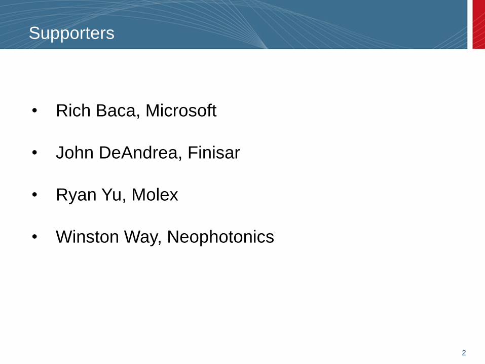
Supporters
• Rich Baca, Microsoft
• John DeAndrea, Finisar
• Ryan Yu, Molex
• Winston Way, Neophotonics
3
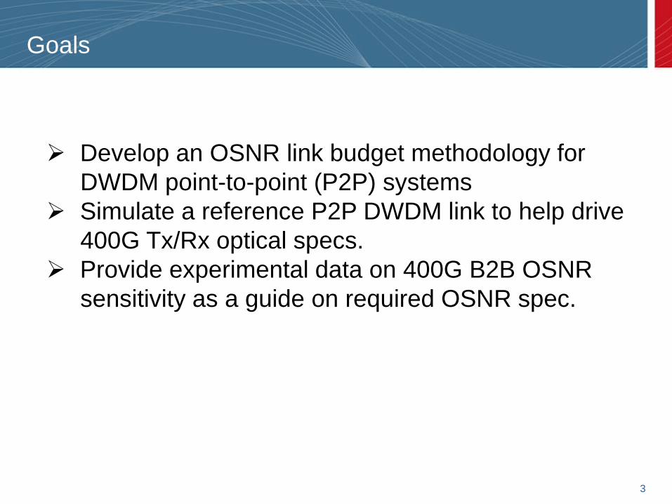
Goals
➢ Develop an OSNR link budget methodology for
DWDM point-to-point (P2P) systems
➢ Simulate a reference P2P DWDM link to help drive
400G Tx/Rx optical specs.
➢ Provide experimental data on 400G B2B OSNR
sensitivity as a guide on required OSNR spec.
4
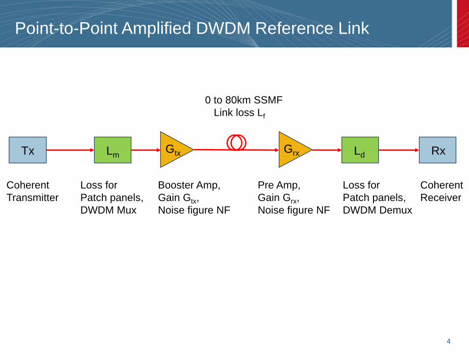
Point-to-Point Amplified DWDM Reference Link
Tx LmGtx Grx Ld Rx
Loss for
Patch panels,
DWDM Mux
Loss for
Patch panels,
DWDM Demux
Booster Amp,
Gain Gtx,
Noise figure NF
Pre Amp,
Gain Grx,
Noise figure NF
0 to 80km SSMF
Link loss Lf
Coherent
Transmitter
Coherent
Receiver
5
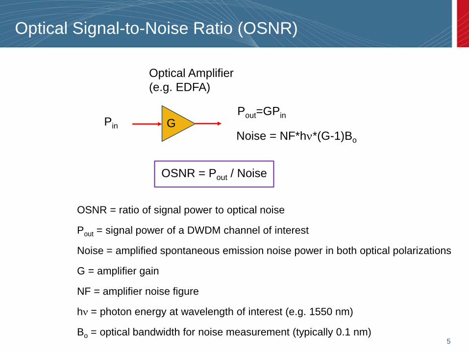
Optical Signal-to-Noise Ratio (OSNR)
G
OSNR = ratio of signal power to optical noise
Pout = signal power of a DWDM channel of interest
Noise = amplified spontaneous emission noise power in both optical polarizations
G = amplifier gain
NF = amplifier noise figure
hn = photon energy at wavelength of interest (e.g. 1550 nm)
Bo = optical bandwidth for noise measurement (typically 0.1 nm)
Pout=GPinPin
Noise = NF*hn*(G-1)Bo
OSNR = Pout / Noise
Optical Amplifier
(e.g. EDFA)
6
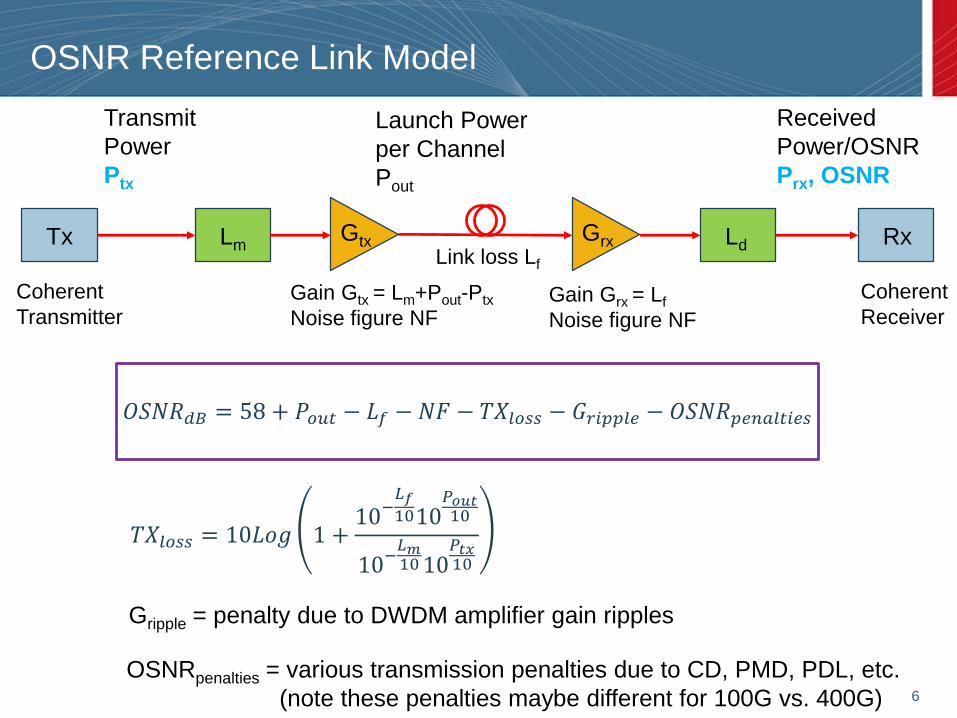
OSNR Reference Link Model
Tx LmGtx Grx Ld Rx
Gain Gtx = Lm+Pout-Ptx
Noise figure NFGain Grx = Lf
Noise figure NF
Link loss Lf
Coherent
Transmitter
Coherent
Receiver
Transmit
Power
Ptx
Launch Power
per Channel
Pout
Received
Power/OSNR
Prx, OSNR
𝑂𝑆𝑁𝑅𝑑𝐵 = 58 + 𝑃𝑜𝑢𝑡 − 𝐿𝑓 − 𝑁𝐹 − 𝑇𝑋𝑙𝑜𝑠𝑠 − 𝐺𝑟𝑖𝑝𝑝𝑙𝑒 − 𝑂𝑆𝑁𝑅𝑝𝑒𝑛𝑎𝑙𝑡𝑖𝑒𝑠
𝑇𝑋𝑙𝑜𝑠𝑠 = 10𝐿𝑜𝑔 1 +10−
𝐿𝑓1010
𝑃𝑜𝑢𝑡10
10−𝐿𝑚1010
𝑃𝑡𝑥10
Gripple = penalty due to DWDM amplifier gain ripples
OSNRpenalties = various transmission penalties due to CD, PMD, PDL, etc.
(note these penalties maybe different for 100G vs. 400G)
7
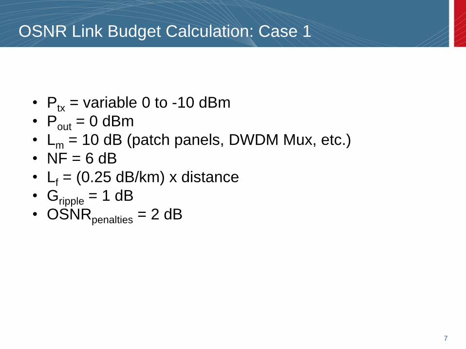
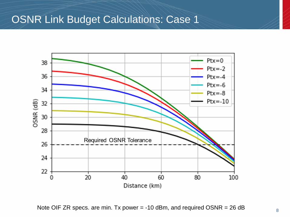
OSNR Link Budget Calculation: Case 1
• Ptx = variable 0 to -10 dBm
• Pout = 0 dBm
• Lm = 10 dB (patch panels, DWDM Mux, etc.)
• NF = 6 dB
• Lf = (0.25 dB/km) x distance
• Gripple = 1 dB
• OSNRpenalties = 2 dB
8
OSNR Link Budget Calculations: Case 1
Note OIF ZR specs. are min. Tx power = -10 dBm, and required OSNR = 26 dB
9
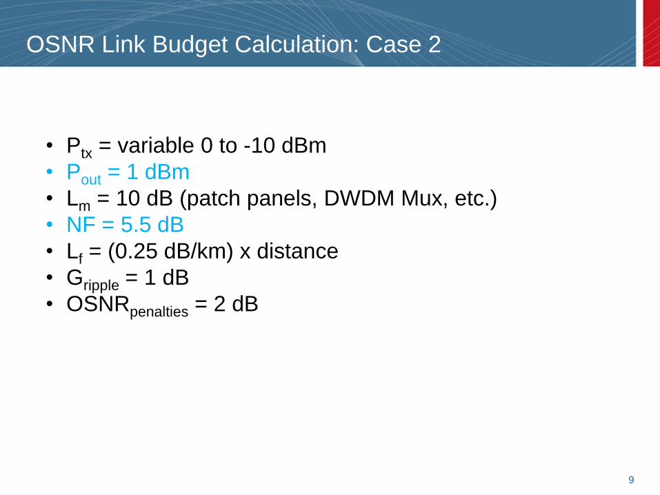
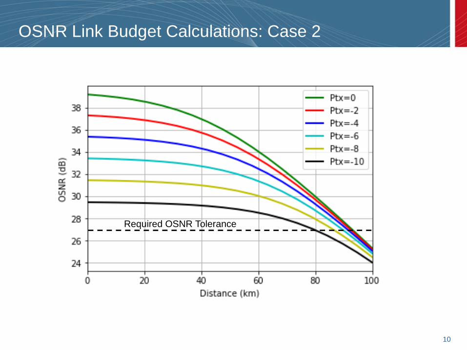
OSNR Link Budget Calculation: Case 2
• Ptx = variable 0 to -10 dBm
• Pout = 1 dBm
• Lm = 10 dB (patch panels, DWDM Mux, etc.)
• NF = 5.5 dB
• Lf = (0.25 dB/km) x distance
• Gripple = 1 dB
• OSNRpenalties = 2 dB
10
OSNR Link Budget Calculations: Case 2
Required OSNR Tolerance
11
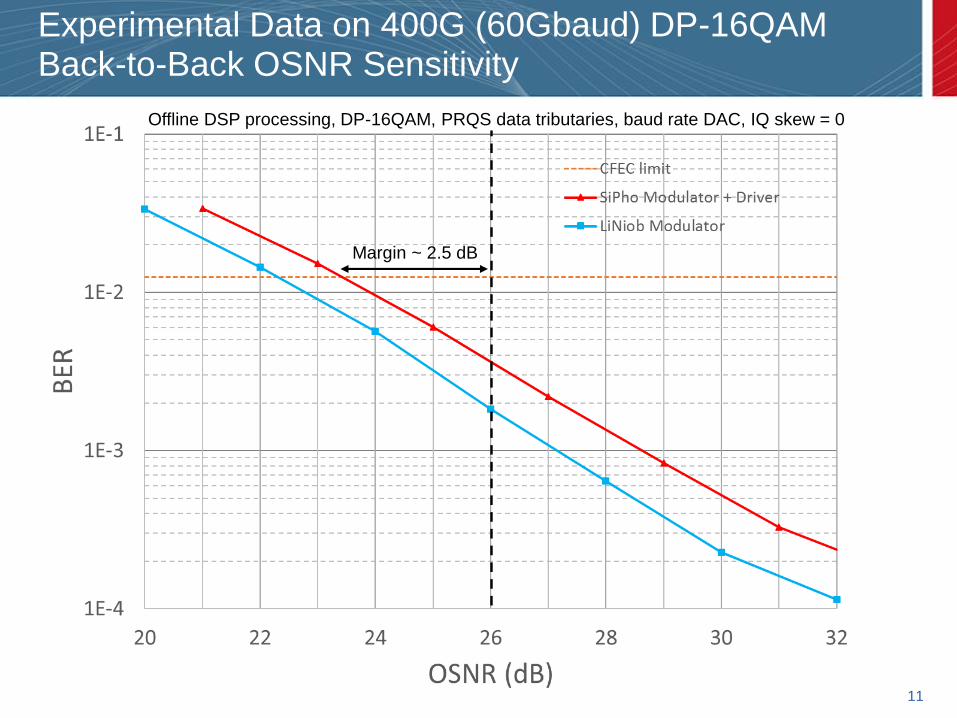
Experimental Data on 400G (60Gbaud) DP-16QAM Back-to-Back OSNR Sensitivity
Margin ~ 2.5 dB
Offline DSP processing, DP-16QAM, PRQS data tributaries, baud rate DAC, IQ skew = 0
12
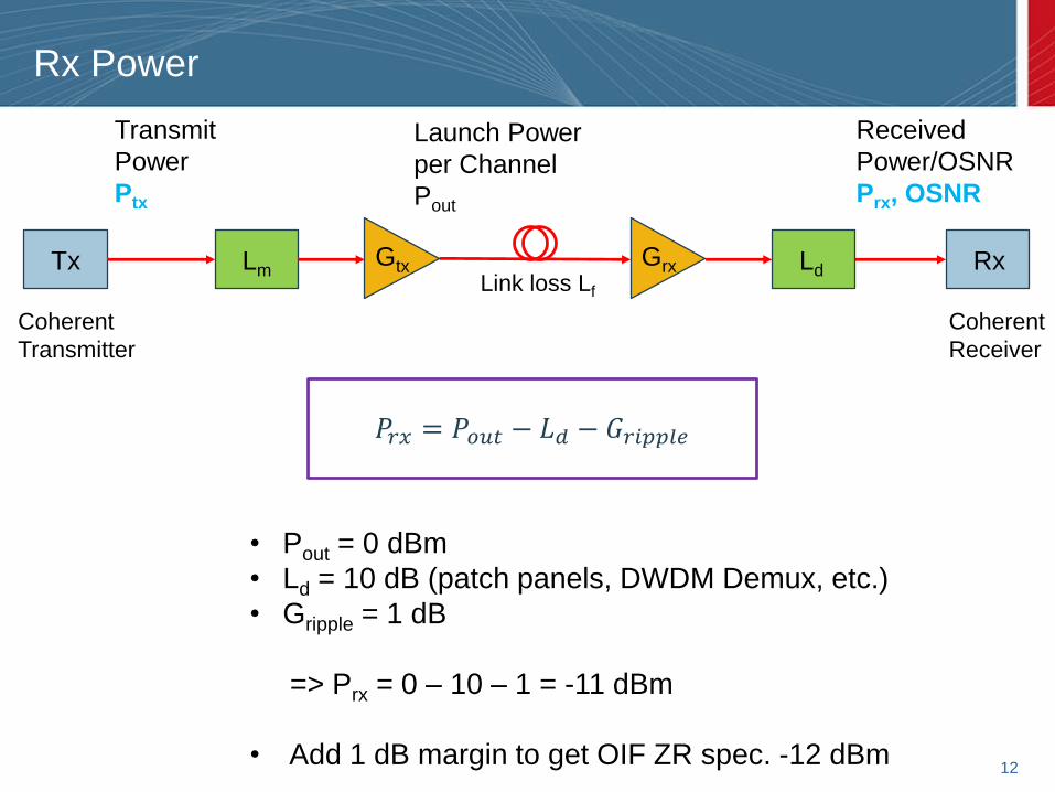
Rx Power
Tx LmGtx Grx Ld Rx
Link loss Lf
Coherent
Transmitter
Coherent
Receiver
Transmit
Power
Ptx
Launch Power
per Channel
Pout
Received
Power/OSNR
Prx, OSNR
𝑃𝑟𝑥 = 𝑃𝑜𝑢𝑡 − 𝐿𝑑 − 𝐺𝑟𝑖𝑝𝑝𝑙𝑒
• Pout = 0 dBm
• Ld = 10 dB (patch panels, DWDM Demux, etc.)
• Gripple = 1 dB
=> Prx = 0 – 10 – 1 = -11 dBm
• Add 1 dB margin to get OIF ZR spec. -12 dBm
13
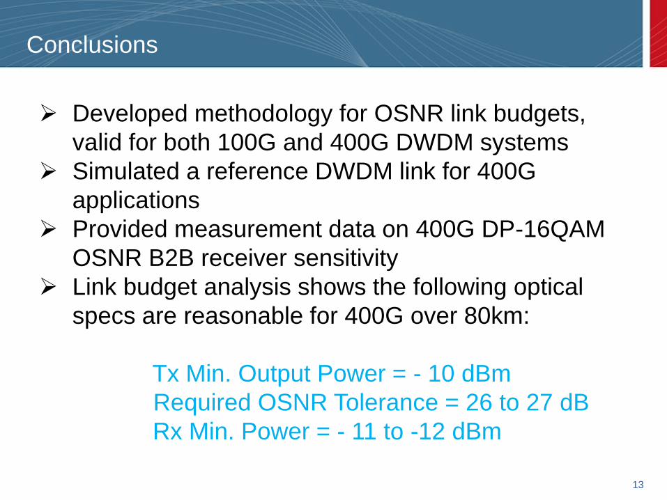
Conclusions
➢ Developed methodology for OSNR link budgets,
valid for both 100G and 400G DWDM systems
➢ Simulated a reference DWDM link for 400G
applications
➢ Provided measurement data on 400G DP-16QAM
OSNR B2B receiver sensitivity
➢ Link budget analysis shows the following optical
specs are reasonable for 400G over 80km:
Tx Min. Output Power = - 10 dBm
Required OSNR Tolerance = 26 to 27 dB
Rx Min. Power = - 11 to -12 dBm


![Optical Signal to Noise Ratio (OSNR) - Optiwave · Optical Signal to Noise Ratio (OSNR) [dB] is the measure of the ratio of signal power to noise power in an optical channel. International](https://img.pdfslide.us/doc/110x75/5e82df92497562069a7d7b0e/optical-signal-to-noise-ratio-osnr-optiwave-optical-signal-to-noise-ratio-osnr.jpg)


![Optical Signal to Noise Ratio (OSNR)cdn.optiwave.com/wp-content/uploads/2015/10/TC... · Optical Signal to Noise Ratio (OSNR) [dB] is the measure of the ratio of signal power to noise](https://img.pdfslide.us/doc/110x75/5aa6ef427f8b9a6d5a8ba223/optical-signal-to-noise-ratio-osnrcdn-signal-to-noise-ratio-osnr-db-is-the.jpg)