Embed Size (px)
Citation preview
Progress in the Development
of Osmotic PowerPresented at the 2011 Quingdao International Conference
on Desalination and Water Reuse byWerner Kofod Nielsen, Senior Advisor, Statkraft
STATKRAFT IS EUROPE'S LEADER IN RENEWABLE ENERGY. THE GROUP
DEVELOPS AND GENERATES HYDROPOWER, WIND POWER, GAS
POWER AND DISTRICT HEATING, AND IS A MAJOR PLAYER ON THE EUROPEAN ENERGY EXCHANGES.
Gas power
86%
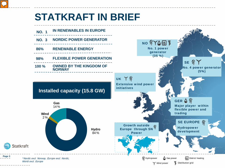
FLEXIBLE POWER GENERATION
RENEWABLE ENERGY
IN RENEWABLES IN EUROPENO. 1
98%
STATKRAFT IN BRIEF
Page 3
100 % OWNED BY THE KINGDOM OF NORWAY
NO. 3 NORDIC POWER GENERATOR
Installed capacity (15.8 GW)
*Nordic excl. Norway, Europe excl. Nordic, World excl. Europe
NONo. 1 powergenerator
(35 %)
SENo. 4 power generator
(5%)
UKExtensive wind power initiatives
GER
Growth outside Europe through SN
Power
Major player within flexible power and trading
Hydropower
Wind power Distribution grid
District heating
Hydro84 %
Wind2 %
Gas14 %
SE EUROPEHydropower development
STATKRAFT’S BASIC BUSINESS CONCEPT
Environment – friendly power production
Page 4 THIS IS A DUMMY TITLE
PRESSURE RETARDED OSMOSIS (PRO) OR OSMOTIC POWER
5 Companypresentation 2009
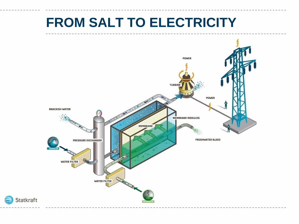
FROM SALT TO ELECTRICITY
Forecast 2020
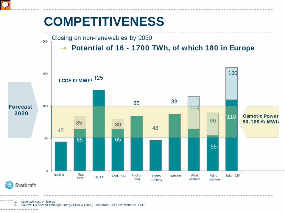
COMPETITIVENESS
Hydro, running
Biomass
65
115
Wind, offshore
55
90
65
110
160
Solar, CSPNuclear
85
Gas, CCGT Oil, CC
65
Wind, onshore
80
Coal, PCC Hydro, dam
LCOE €/MWh1
1. Levelized cost of Energy2. Source: EU Second Strategic Energy Review (2008), Moderate fuel price scenario; BCG
Osmotic Power50-100 €/MWh
Potential of 16 - 1700 TWh, of which 180 in Europe
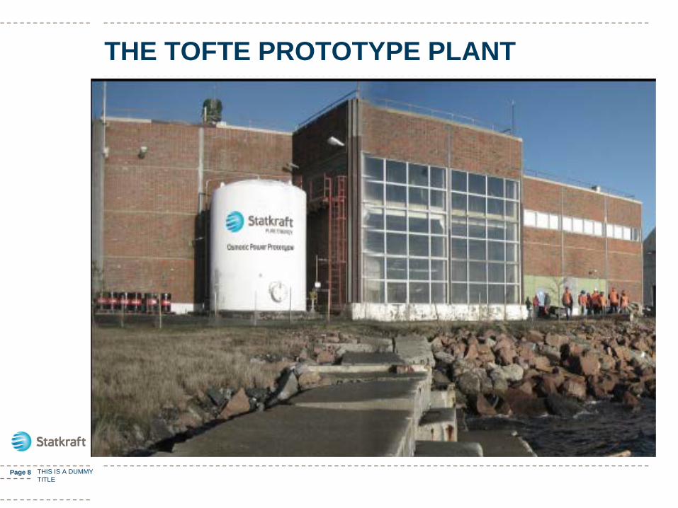
THE TOFTE PROTOTYPE PLANT
Page 8 THIS IS A DUMMY TITLE
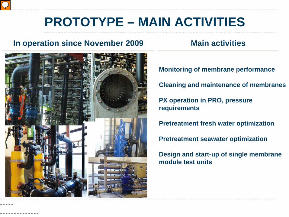
PROTOTYPE – MAIN ACTIVITIESIn operation since November 2009 Main activities
Monitoring of membrane performance
Cleaning and maintenance of membranes
PX operation in PRO, pressure requirements
Pretreatment fresh water optimization
Pretreatment seawater optimization
Design and start-up of single membrane module test units
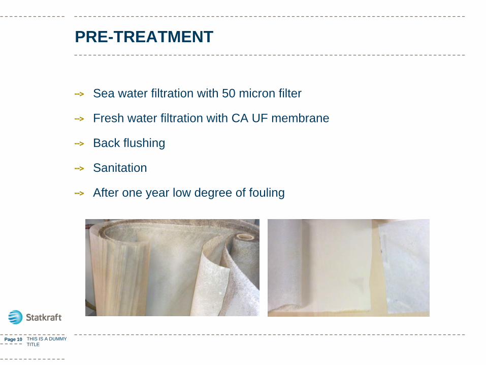
PRE-TREATMENT
Sea water filtration with 50 micron filter
Fresh water filtration with CA UF membrane
Back flushing
Sanitation
After one year low degree of fouling
Page 10 THIS IS A DUMMY TITLE
AFTER ONE YEAR
1. generation membranes and elementsCA membranes, PRO spiral wound designInstalled November 2009
2. generation membranes and elementsTFC membranes, PRO spiral wound designInstalled January 2011
28 m2 per element, 66 elements
Page 11 THIS IS A DUMMY TITLE
RESULTS
Experience with operation of a complete PRO plant
Experience with spiral wound elements
Measurement of power efficiency
Fine tuning of operating parameters
Results with 1. generation CA membranes
Results with 2. generation TFC membranes
Page 12 THIS IS A DUMMY TITLE
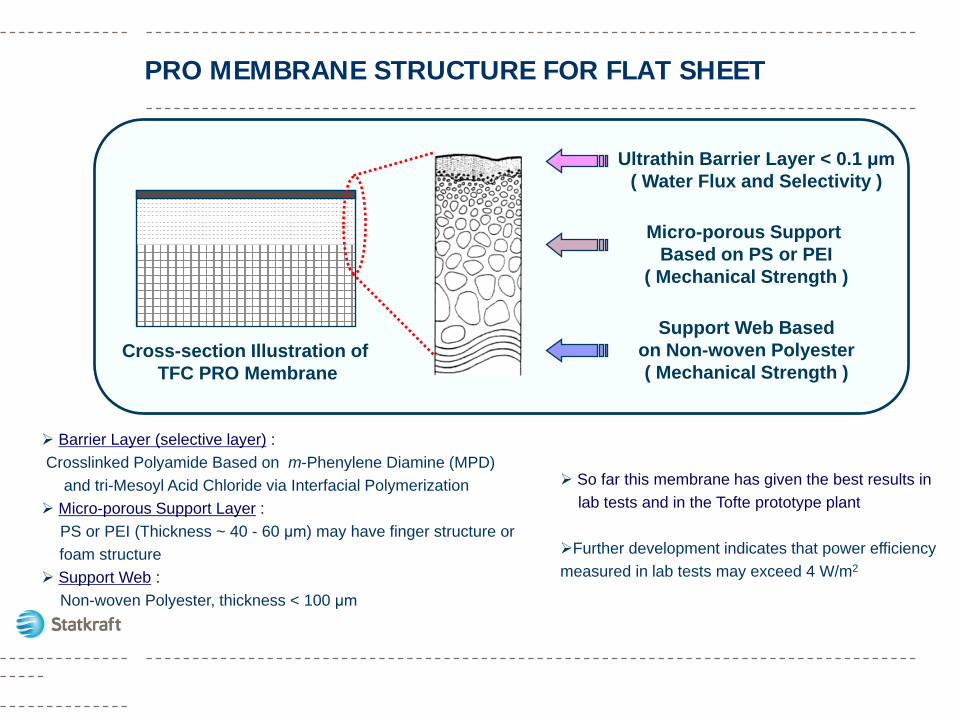
PRO MEMBRANE STRUCTURE FOR FLAT SHEET
Barrier Layer (selective layer) : Crosslinked Polyamide Based on m-Phenylene Diamine (MPD)
and tri-Mesoyl Acid Chloride via Interfacial Polymerization Micro-porous Support Layer :
PS or PEI (Thickness ~ 40 - 60 μm) may have finger structure orfoam structure
Support Web :Non-woven Polyester, thickness < 100 μm
Support Web Basedon Non-woven Polyester( Mechanical Strength )
Micro-porous Support Based on PS or PEI
( Mechanical Strength )
Ultrathin Barrier Layer < 0.1 μm( Water Flux and Selectivity )
Cross-section Illustration of TFC PRO Membrane
So far this membrane has given the best results in lab tests and in the Tofte prototype plant
Further development indicates that power efficiency measured in lab tests may exceed 4 W/m2
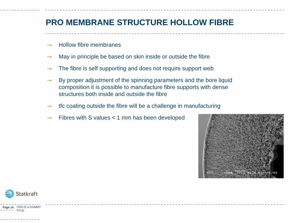
PRO MEMBRANE STRUCTURE HOLLOW FIBRE
Hollow fibre membranes
May in principle be based on skin inside or outside the fibre
The fibre is self supporting and does not require support web
By proper adjustment of the spinning parameters and the bore liquid composition it is possible to manufacture fibre supports with dense structures both inside and outside the fibre
tfc coating outside the fibre will be a challenge in manufacturing
Fibres with S values < 1 mm has been developed
Page 14 THIS IS A DUMMY TITLE
15
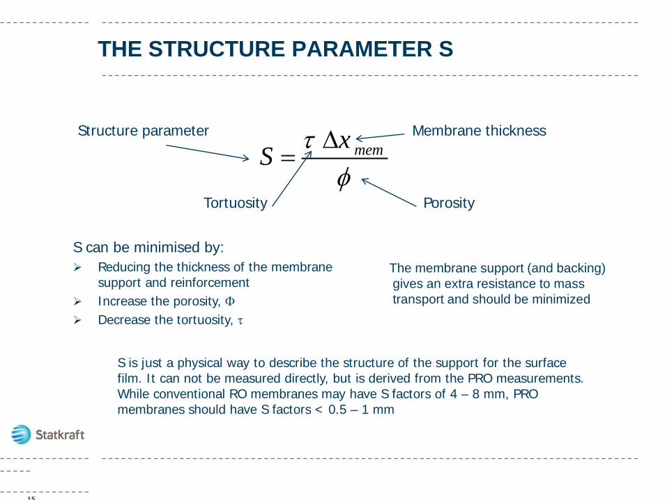
THE STRUCTURE PARAMETER S
The membrane support (and backing) gives an extra resistance to mass transport and should be minimized
memxS τφ∆
=
S can be minimised by: Reducing the thickness of the membrane
support and reinforcement Increase the porosity, Φ Decrease the tortuosity, τ
Structure parameter Membrane thickness
PorosityTortuosity
S is just a physical way to describe the structure of the support for the surface film. It can not be measured directly, but is derived from the PRO measurements. While conventional RO membranes may have S factors of 4 – 8 mm, PRO membranes should have S factors < 0.5 – 1 mm
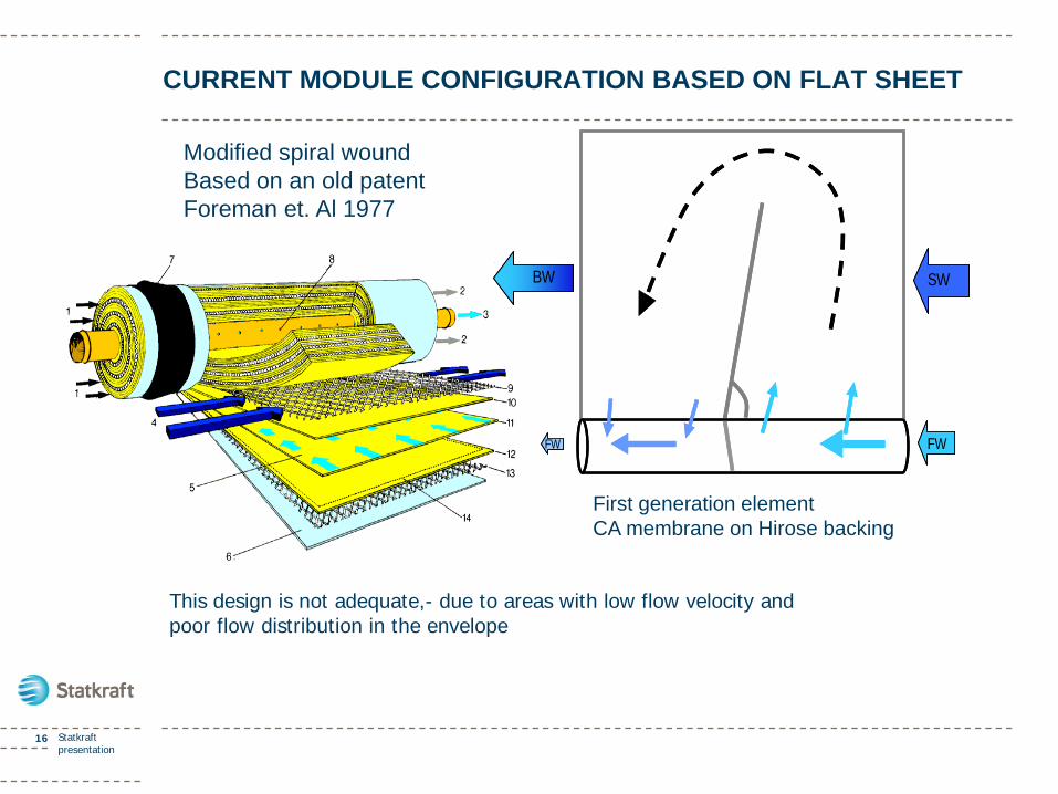
CURRENT MODULE CONFIGURATION BASED ON FLAT SHEET
16 Statkraft presentation
Modified spiral woundBased on an old patentForeman et. Al 1977
FW FW
BW SW
FW FW
BW SW
First generation elementCA membrane on Hirose backing
This design is not adequate,- due to areas with low flow velocity and poor flow distribution in the envelope
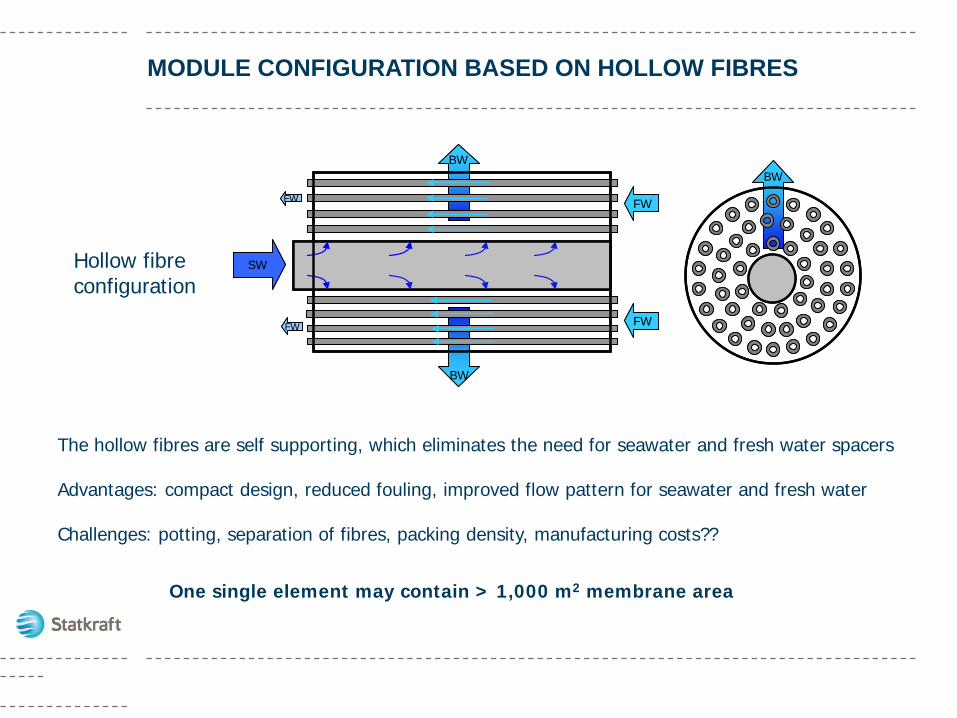
MODULE CONFIGURATION BASED ON HOLLOW FIBRES
Hollow fibre configuration
BWBW
SW
FW
BW
BW
FW
FW FW
SW
FW
BW
BW
FW
FW FW
The hollow fibres are self supporting, which eliminates the need for seawater and fresh water spacers
Advantages: compact design, reduced fouling, improved flow pattern for seawater and fresh water
Challenges: potting, separation of fibres, packing density, manufacturing costs??
One single element may contain > 1,000 m2 membrane area
Page 18 THIS IS A DUMMY TITLE
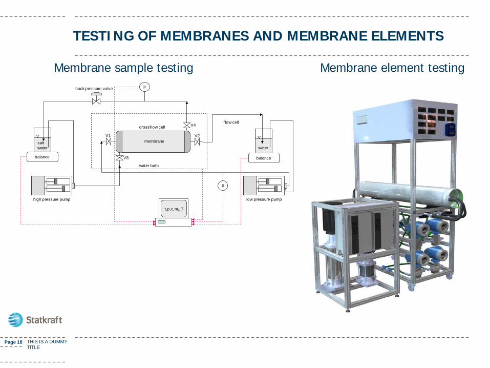
TESTING OF MEMBRANES AND MEMBRANE ELEMENTS
balance
salt water
balance
water
high pressure pump low pressure pump
back pressure valve
V1 V2
V3
V4
p
t,p,c,mi, T
f low cell
water bath
crossf low cell
membrane
p
Membrane sample testing Membrane element testing
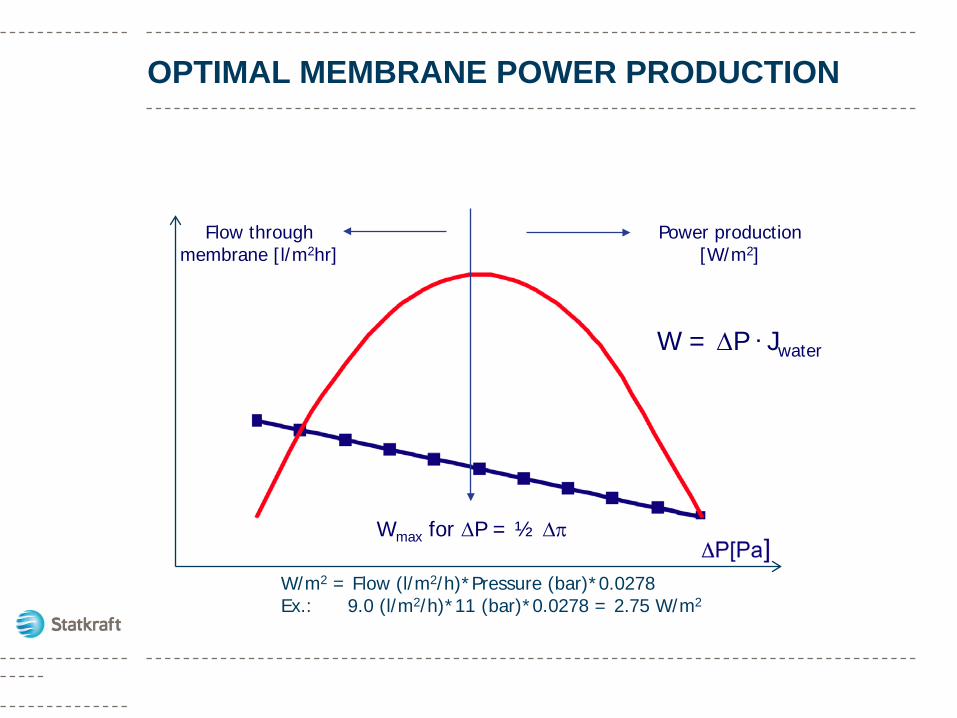
OPTIMAL MEMBRANE POWER PRODUCTION
Wmax for ∆P = ½ ∆π
W = ∆P . Jwater
Flow through membrane [l/m2hr]
Power production [W/m2]
W/m2 = Flow (l/m2/h)*Pressure (bar)*0.0278Ex.: 9.0 (l/m2/h)*11 (bar)*0.0278 = 2.75 W/m2
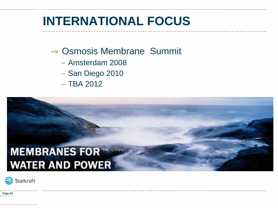
INTERNATIONAL FOCUS
Osmosis Membrane SummitAmsterdam 2008San Diego 2010TBA 2012
Page 20
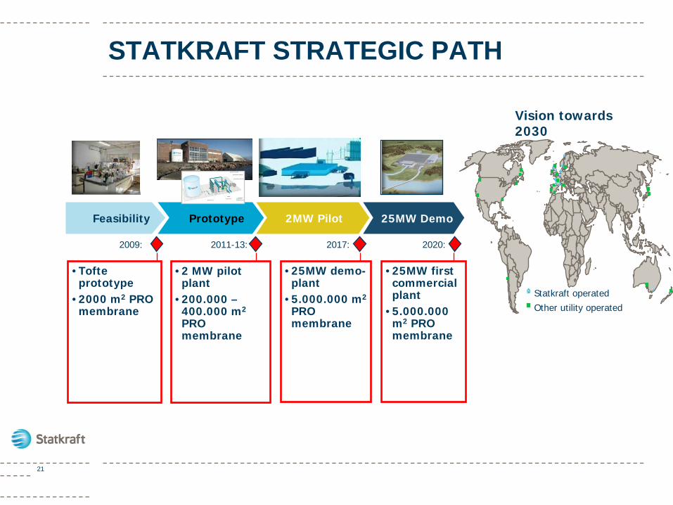
Feasibility Prototype 2MW Pilot 25MW Demo
2011-13: 2017: 2020:
STATKRAFT STRATEGIC PATH
2009:
•Tofte prototype
•2000 m2 PRO membrane
•2 MW pilot plant
•200.000 –400.000 m2
PRO membrane
•25MW demo-plant
•5.000.000 m2
PRO membrane
•25MW first commercial plant
•5.000.000 m2 PRO membrane
Vision towards 2030
21
Statkraft operatedOther utility operated
LATEST NEWS
On June 20th Statkraft and Nitto Denko/Hydranauticssigned an agreement with the objectives of:
Development and supply of membranes for osmotic power
Nitto Denko/Hydranautics will develop membranes specifically designed for the use in large scale osmotic power plants
The agreement will accelerate the development of the new renewable energy
The development of more efficient membranes will contribute to making the technology competitive with other new, renewable energy sources and will bring osmotic power further towards future commercialization
Page 22 THIS IS A DUMMY TITLE
CONCLUDING REMARKS
Osmotic Power is a promising renewable ocean energy source
The estimated energy costs for Osmotic Power is comparable with other renewable energy sources
Existing RO membranes, modules and pre-treatment are not suitable for Osmotic Power
Key focus areas are PRO membranes, PRO membrane modules and pre-treatment of fresh and sea water
Prototype and pilot demonstration plants are accelerating the development
Page 23
Page 24 THIS IS A DUMMY TITLE