Embed Size (px)
Citation preview

www.yenista.com
-
OSICS
Catalogue
● OSICS Mainframe
● Compact Tunable Lasers
● Compact Transmission Lasers
● Passive Optical Functions and Sources


www.yenista.com
Information and specifications are subject to change without notice.
OSICS-Overview_DS_201309, September 2013.
-
The OSICS multifunction modular platform offers
the highest flexibility and largest choice of
pluggable modules required in fiber-optic
component and system testing, particularly for
DWDM system evaluations.
Compact Tunable Lasers
OSICS ECL
Standard tunable external cavity lasers
(step mode).
Compact Transmission Lasers
Broadband Light Sources
Passive Optical Functions and Sources
OSICS TLS-50
Fast wavelength switching lasers on the 50 GHz
ITU grid.OSICS SLD
Superluminescent light emitting diodes.
OSICS SWT
Optical shutters and switches.
Test Systems
OSICS FBL
Full-band tunable laser from 1260 to 1680 nm
(step mode).
OSICS Mainframe
Up to 8 pluggable modules can be mixed and
matched in a single OSICS mainframe, thus
fulfilling all needs for applications requiring, for
example, multi-wavelength sources.
OSICS T100
Ultra-low SSE tunable external cavity lasers
(step mode).
OSICS DFB
Distributed feedback laser diodes for DWDM
OSICS TLS-AG
Narrow linewidth tunable lasers for coherent
transmission.
OSICS BKR
Variable back reflectors.
OSICS ATN
High power optical attenuators.
OSICS WDM
WDM comb of 8 transmission lasers (DFB, TLS-50
or TLS-AG) with a Mux/Demux.
● Ease of Use
● 24/7 Use for manufacturing
● Affordable Price, even if you start with a
single module
● Largest Choice of Laser Sources
Key Features
8-Channel Multifunction Platform
OSICS Multifunction Platform
+65 6631 8520 [email protected]
+33 2 9648 3716 [email protected]
+86 21 6225 3573 [email protected]
[email protected]+1 609 423 0890
China
Asia Pacific
Americas
Europe, Middle East & AfricaAccessoriesJumpers, cover plates and handles.

www.yenista.com
Information and specifications are subject to change without notice.
OSICS-Mainframe_DS_201309, September 2013.
OSICS Mainframe8-Channel Mainframe
-
The OSICS mainframe can host up to eight
pluggable modules for matching your
particular test applications. It is easy-to-use
thanks to the front panel interface that offers
direct control of the eight modules. Moreover,
the mainframe is reliable and cost effective for
laboratory use as well as for 24/7 use in
manufacturing plants.
The front panel interface of the mainframe
comprises a display and rotary knob allowing easy
navigation in the module tabs. They enable fast
setup and control of the parameter values. During
normal operation, the parameters of all the
modules are displayed simultaneously in the main
tab and updated in real-time.
Front Panel
Connectors for remote operation are located at
the back panel of the mainframe: RS-232, GPIB
and Interlock.
There are also 18 BNC connectors for different
purposes. The first is for synchronization of the
mainframe and the second for application of an
external modulation signal to the mainframe.
In addition, there are two BNC connectors per
module: one for monitoring of power, current,
and temperature and the other for an analog
modulation output signal. Such a pair is only
operating if supported by the module.
Back Panel
448 x 133 x 370 mm
100 to 240 V, 50 to 60 Hz
8.1 kgWeight (w/o modules)
Power Supply
Dimensions (W x H x D)
Specifications
+65 6631 8520 [email protected]
+33 2 9648 3716 [email protected]
+86 21 6225 3573 [email protected]
[email protected]+1 609 423 0890
China
Asia Pacific
Americas
Europe, Middle East & Africa

www.yenista.com
Information and specifications are subject to change without notice.
OSICS-T100_DS_201309, September 2013.
Wavelength Setting Resolution 0.01 nm (0.001 nm option R)
Tuning Speed*5 10 nm/s typical
Wavelength Setting Repeatability ±0.01 nm typical
Wavelength ±0.01 nm/h (±0.01 nm/24 h typical)
Output Power ±0.01 dB/h (±0.01 dB/24 h typical)
Analogue Modulation 150 Hz to 200 MHz (external)
Digital Modulation 500 Hz to 1 MHz (internal & external)
Relative Intensity Noise*3,*4 –145 dB/Hz typical
Side Mode Suppression Ratio ≥45 dB
Signal to Source Spontaneous Emission Ratio*1 > 90 dB / 0.1 nm typical
Spectral Width (FWHM)>100 MHz (coherence control on)
150 kHz typical (coherence control off)
Output Fiber Type SMF or PMF (option M)
Output Connector FC / APC narrow key
Laser Safety Classification Class 1M
Wavelength Range (nm)P = +3 dBm
P = +6 dBm
Stability*2, *3
1490-1610
T100 1550
1520-1590
1560-1680
T100 1620
1580-1660
1360-1470
T100 1415
1390-1445
1260-1360
T100 1310
1290-1340
*1. Measured over a 0.1 nm bandwidth ±1nm from the signal.
*2. At constant temperature.
*3. Measured at 0 dBm output power.
*4. Measured at 100 MHz.
*5. With the high resolution option (R) the tuning speed is 2.5 nm/s typical.
Wavelength Setting Accuracy*3 ±0.2 nm
OSICS T100Tunable Laser Module
OSICS T100 are cost effective, external cavity tunable
lasers modules utilizing Yenista's patented T100 cavity.
This gives a minimum of 100 nm tuning range with
narrow linewidth, high output power and ultra-low
optical noise. This low noise significantly increases the
dynamic range of a measurement. The OSICS platform
provides front panel and remote control interfaces.
1465-1575
T100 1520
1495-1555
1520-1630
T100 1575
1540-1610
● Simple front panel or remote control
● ≥100 nm tuning range
● +6 dBm output power
● Ultra-low SSE noise
● Narrow linewidth
● O, E, S, C, L & U bands
● External cavity design
● Modulation up to 1 MHz
Key Features
+65 6631 8520 [email protected]
+33 2 9648 3716 [email protected]
+86 21 6225 3573 [email protected]
[email protected]+1 609 423 0890
China
Asia Pacific
Americas
Europe, Middle East & Africa
All specifications are given after 60 minutes warm-up and apply for wavelengths not equal to any water absorption line.

www.yenista.com
Information and specifications are subject to change without notice.
OSICS-ECL_DS_201309, September 2013.
OSICS ECL 1560
The OSICS ECL 1560/P6 module is a high-
performance external cavity tunable laser
using TUNICS technology which leeds to a
high output power over the whole tuning
range.
The OSICS platform provides front panel
and remote control interfaces.
Tunable Laser Module
Key Features
● +6 dBm output power
● 80 nm tuning range
+65 6631 8520 [email protected]
+33 2 9648 3716 [email protected]
+86 21 6225 3573 [email protected]
[email protected]+1 609 423 0890
China
Asia Pacific
Americas
Europe, Middle East & Africa
● External cavity design
● C & L bands
● Narrow linewidth
● Modulation up to 1 MHz
● Simple front panel or remote control
Wavelength Setting Resolution 0.01 nm (0.001 nm option R)
Tuning Speed*5 10 nm/s typical
Wavelength Setting Repeatability ±0.01 nm typical
Wavelength ±0.01 nm/h (±0.01 nm/24 h typical)
Output Power ±0.01 dB/h (±0.01 dB/24 h typical)
Analogue Modulation 150 Hz to 200 MHz (external)
Digital Modulation 500 Hz to 1 MHz (internal & external)
Relative Intensity Noise*3,*4 –145 dB/Hz typical
Side Mode Suppression Ratio ≥45 dB
Signal to Source Spontaneous Emission Ratio*1 > 90 dB / 0.1 nm typical
Spectral Width (FWHM)>100 MHz (coherence control on)
150 kHz typical (coherence control off)
Output Fiber Type SMF or PMF (option M)
Output Connector FC / APC narrow key
Laser Safety Classification Class 1M
Wavelength Range (nm)P = +0 dBm
P = +6 dBm
Stability*2, *3
*1. Measured over a 0.1 nm bandwidth ±1nm from the signal.
*2. At constant temperature.
*3. Measured at 0 dBm output power.
*4. Measured at 100 MHz.
*5. With the high resolution option (R) the tuning speed is 2.5 nm/s typical.
Wavelength Setting Accuracy*3 ±0.2 nm
All specifications are given after 60 minutes warm-up and apply for wavelengths not equal to any water absorption line.
1530 to 1580
1520 to 1600
Specifications

Information and specifications are subject to change without notice.
OSICS-TLS-AG_DS_201309, September 2013.
OSICS TLS-AG
The OSICS TLS-AG modules are tunable laser sources
with high output power and low linewidth thanks to
external cavity design. The wavelength can be tuned to
any wavelength in C or L band.
With more than +13 dBm (20 mW) output power, plus
high power and wavelength stability, this is the ideal
laser for coherent WDM transmission testing.
● Low linewidth: <100 kHz
Ideal for use as local oscillator in coherent
transmission.
● SBS suppression
● Turn on and off the laser
in one click
● High power: +13 dBm
Ideal for optical amplifier testing or WDM
test-beds.
● Handy Operation
The platform user-friendly interface allows
direct adjustment of the laser from the front
panel, as well as simultaneous display of all
power and wavelength values on the OSICS
front panel.
Key FeaturesLaser for Coherent WDM Transmission
-145 dB/Hz
50 dB
Yes
<100 kHz
±0.2 dB
±0.03 dB
20 s
±0.5 GHz (±4 pm)
+7 to +14 dBm
196.25 to 191.5 THz(1527.60 to 1565.5 nm)
Stimulated Brillouin Scattering
(SBS) Suppression Ability*4
Power Stability*3
Absolute Output Power Deviation
Accross Tuning Range
Instantaneous Linewidth
(FWHM)
Tuning Speed
(typ. between two channels)*2
Relative Frequency
(Wavelength) Accuracy (typ.)
Power Range (typ.)
Wavelength Range
Signal to Spontaneous
Emission Ratio (typ.)*5
20 mW (+13 dBm)
C Band L Band
Grid SelectionAdjustable to any wavelength grid
(ITU-T 100 GHz, 50 GHz and arbitrary grid)
Output Power
Side Mode Suppression Ratio
(typ.)
Relative Intensity Noise*6
(RIN)
Operating Temperature Range
Module
Interfaces
Optical Interface
Dimensions
(WxHxD) & Weight
190.95 to 186.35 THz(1570.01 to 1608.76 nm)
60 dB
+15 to +35°C (+59 to +95°F)
FC/APC connector on polarization
maintaining fiber PER >20 dB
35 x 130 x 250 mm (single slot), 1 kg
Specifications
*1. ±2.5 GHz (±22 pm) end of life.*2. 30 s max, including power stabilisation.*3. At a constant temperature.
*4. At a dither frequency of 20.8 kHz and a FM p-p modulation width from 0 to 1000 MHz.*5. Integrated over a 0.1 nm band.*6. At +13 dBm, average RIN on 10 MHz-40 GHz
WDM Tunable Laser Source
● Selection of pre-configured
channel or any wavelength in the
covered wavelength range
● Polarization maintaining output for use with
external modulator
Absolute Frequency
(Wavelength) Accuracy (typ.)*1
ControlStatus LED,
laser on/off button
Frequency Setting Resolution*3 Down to 1 MHz
±1.5 GHz (±12 pm)
www.yenista.com
+65 6631 8520 [email protected]
+33 2 9648 3716 [email protected]
+86 21 6225 3573 [email protected]
[email protected]+1 609 423 0890
China
Asia Pacific
Americas
Europe, Middle East & Africa
Laser Safety Classification Class 1 M

www.yenista.com
Information and specifications are subject to change without notice.
OSICS-TLS-50_DS_201309, September 2013.
OSICS TLS-50WDM Tunable Laser Source
The OSICS TLS-50 modules are tunable laser sources
with high output power and very good wavelength
accuracy based on the ITU-T grid. The wavelength can
be switched over about 90 channels of the ITU-T grid by
50 GHz steps, covering around 35 nm in C or L band.
With +13 dBm (20 mW) output power as well as
excellent power and wavelength stability, this is the
ideal laser for WDM routing testing.
● Wavelength locked to
50 GHz ITU-T grid
● Polarization maintaining output for use with
external modulator
● SBS suppression
● Internal AM and FM modulation
● Wavelength switching
down to 20 ms
● High power: +13 dBm in C band
Ideal for optical amplifier testing or WDM
test-beds.
● Real time & easy operation
The platform user-friendly interface allows real-time
adjustment of the laser, as well as simultaneous
display of all power and wavelength values on the
OSICS front panel.
Key FeaturesLaser for WDM Routing
Absolute frequency accuracy over C band
Frequency stability over 12 hours
>40 dB (45 dB typ.)
10 kHZ to 100 kHz
Yes
<5 MHz (1 MHz typ.)
0.5 dB
±0.05 dB
<20 ms
50 GHz
±1.8 GHz
+8 to +14 dBm
196.1 to 191.7 THz(1528.77 to 1563.86 nm)
Frequency Modulation*5
Stimulated Brillouin Scattering
(SBS) Suppression*4
Power Stability*1, *2
Absolute Power Deviation
Accross Tuning Range
Linewidth (FWHM)
Switching Speed
(typ. between two channels)
Wavelength Accuracy*1
Power Range (typ.)
Wavelength Range
Wavelength Setting
Resolution
Trace Tone
(Amplitude Modulation)*5
20 mW (+13 dBm)
C Band L Band
Number of ITU Channels89
(50 GHz spacing)
93
(50 GHz spacing)
Output Power
Side Mode Suppression Ratio*1
Relative Intensity Noise*1,*2,*3
(RIN)
Operating Temperature Range
Module
Interfaces
Optical Interface
Dimensions
(WxHxD) & Weight
191.1 to 186.5 THz(1568.77 to 1607.47 nm)
10 mW (+10 dBm)
+5 to +11 dBm
10 kHZ to 500 kHz
-145 dB/Hz
+15 to +35°C (+59 to +95°F)
FC/APC connector on polarization
maintaining fiber PER >20 dB
35 x 130 x 250 mm (single slot), 1 kg
Specifications
*1. After warm-up of 60 s.*2. Over 2 h at a constant temperature.*3. Average RIN on 1-100 GHz. -110 dB/Hz on 10 MHz-1 GHz.
*4. Enable: on/off. Linewidth from 250 to 1000 MHz depending on the selected frequency modulation.*5. Waveshape selection: sinusoidal or triangular.*6. Tone depth: up to 10%
+65 6631 8520 [email protected]
+33 2 9648 3716 [email protected]
+86 21 6225 3573 [email protected]
[email protected]+1 609 423 0890
China
Asia Pacific
Americas
Europe, Middle East & Africa
Laser Safety Classification Class 1 M

www.yenista.com
Information and specifications are subject to change without notice.
OSICS-DFB_DS_201309, September 2013.
OSICS DFB
The OSICS DFB modules are based on high-
performance distributed feedback laser diodes.
Distributed Feedback Laser
Key Features
● OSICS DFB is also available at 1310 nm
and other wavelengths are available on
request.
OSICS DFB Typical Application: WDM Grid Simulation
FC/APC connector on PMF
PER >17 dB
>140 dB/Hz (typ.)
<10 MHz
±0.005 nm / h
(±0.005 nm / 24 h typ.)
±0.03 nm
+13 dBm
Relative
Intensity Noise*2,*5
Optical Interface
Spectral Width
(FWDM)
Power Stability*2,*3,*4
1.6 nm (1.8 nm
OSICS
DFB C & L band
ITU-T Wavelength 1529.55-1610.05 nm*1
Side Mode
Suppression Ratio*2
1310 nm ±10 nm
>35 dB (45 dB typ.)
OSICS
DFB 1310
OSICS
DFB SP
Other
wavelengths:
please consult
for availability
and detailed
specifications
*1. The ITU-T wavelength is user-selected at time of order on the
ITU-T grid, using the following format: OSICS-DFB-XXX.XX where
XXX.XX is the frequency in THz.
*2. After warm-up, for Pmax output power.
*3. At a constant temperature.
*4. Measured with an APC connector on the powermeter side.
*5. Measured at an electrical frequency of 100 MHz.
Specifications
● OSICS DFB offers +13 dBm optical power
coupled in a polarization maintaining fiber with
a remarkable 5 pm wavelength stability over
one hour.
● Each module can be controlled from the
front panel of the mainframe or through the
remote interface. The modules and the
mainframe offer a full suite of internal and
external modulation capabilities.
● The internal wavelength calibration yields
a 30 pm accuracy and the wavelength can be
finely tuned over 1.8 nm (typ.) with the internal
temperature control.
Output Power
Wavelength
Tunning RangeWavelength
Accuracy*2
Wavelength
Stability*2,*3,*4
±0.01 dB / h
(±0.01 dB / 24 h typ.)
+65 6631 8520 [email protected]
+33 2 9648 3716 [email protected]
+86 21 6225 3573 [email protected]
[email protected]+1 609 423 0890
China
Asia Pacific
Americas
Europe, Middle East & Africa
● SBS suppression function
Laser Safety
Classification Class 1 M
Analogue
Modulation
Digital
Modulation
150 Hz-200 MHz (external)
1 Hz-1 MHz (internal or external)
● Modulation up to 1 MHz

www.yenista.com
Information and specifications are subject to change without notice.
OSICS-SWT_DS_201309, September 2013.
OSICS SWT
● Low insertion and
polarization dependent loss
Key Features
SMF-28 fiber
30 ms typ.
≥55 dB
>55 dB
≤0.005 dB
SMF*3
Available Configurations
>108
+15 to +35°C (+59 to +95°F)
1 kg (2.21 lb)
Specifications
*1. Typical values including connectors. Maximum insertion loss is 1.4 dB for SMF and 2.0 dB for PMF.*2. On the whole wavelength range.*3. Specifications apply for wavelengths not equal to any water absorption line
Optical Switch and Shutter
● Excellent repeatability
● High optical isolation
● Low back reflection
● Broad spectral range
● Switch time of 30 ms
● Single slot module
PMF
Polarisation Dependent Loss*1
Connection Type
Guaranteed Lifetime
(number of cycle)
Switching Time
Return Loss*1
Crosstalk*2
On/Off ratio
(1x1 Shutter Only)
Repeatability*2
Spectral Range (nm)
Insertion Loss*1,*2
Input/Output Fiber Type
Dimensions W x H x D
Weight
Temperature Range
1x1
2x(1x1)
1x2
1x4
2x2
1x1
1x2
1x4
On/Off ratio
(2x(1x1) Shutter Only)
35 x 128 x 230 mm
1.4 x 5.0 x 9.0 in
PM15
≥65 dB
≥80 dB
1260-1630
≤1 dB
PDL ≤ 0.1 dB PER ≥ 20 dB
≤1.5 dB
1480-1630
≤0.01 dB
FC/APC Narrow key
>55 dB
+65 6631 8520 [email protected]
+33 2 9648 3716 [email protected]
+86 21 6225 3573 [email protected]
[email protected]+1 609 423 0890
China
Asia Pacific
Americas
Europe, Middle East & Africa
OSICS SWT is a full suite of fiber optic switch and
shutter modules based on optical prism technology.
These modules are perfect modules for use in
laboratory or manufacturing environment to
automate test set-ups and reduce measurement
uncertainties due to optical connections
www.yenista.com
Information and specifications are subject to change without notice.
OSICS-SWT-APC_DS_201309, September 2013.
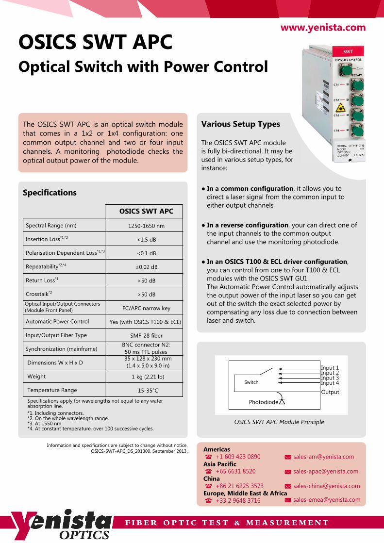
OSICS SWT APC
The OSICS SWT APC is an optical switch module
that comes in a 1x2 or 1x4 configuration: one
common output channel and two or four input
channels. A monitoring photodiode checks the
optical output power of the module.
Various Setup Types
BNC connector N2:
50 ms TTL pulses
SMF-28 fiber
Yes (with OSICS T100 & ECL)
FC/APC narrow key
>50 dB
>50 dB
1250-1650 nm
Polarisation Dependent Loss*1,*3
Synchronization (mainframe)
Automatic Power Control
Return Loss*1
Crosstalk*2
Optical Input/Output Connectors
(Module Front Panel)
±0.02 dBRepeatability*2,*4
Specifications
*1. Including connectors.*2. On the whole wavelength range.*3. At 1550 nm.*4. At constant temperature, over 100 successive cycles.
● In a common configuration, it allows you to
direct a laser signal from the common input to
either output channels
● In a reverse configuration, your can direct one of
the input channels to the common output
channel and use the monitoring photodiode.
Optical Switch with Power Control
OSICS SWT APC
Spectral Range (nm)
Insertion Loss*1,*2
Input/Output Fiber Type
Dimensions W x H x D
Weight
Temperature Range
<1.5 dB
<0.1 dB
35 x 128 x 230 mm
(1.4 x 5.0 x 9.0 in)
1 kg (2.21 lb)
15-35°C
The OSICS SWT APC module
is fully bi-directional. It may be
used in various setup types, for
instance:
● In an OSICS T100 & ECL driver configuration,
you can control from one to four T100 & ECL
modules with the OSICS SWT GUI.
The Automatic Power Control automatically adjusts
the output power of the input laser so you can get
out of the switch the exact selected power by
compensating any loss due to connection between
laser and switch.
OSICS SWT APC Module Principle
Input 1Input 2Input 3Input 4Switch
Output
Photodiode
+65 6631 8520 [email protected]
+33 2 9648 3716 [email protected]
+86 21 6225 3573 [email protected]
[email protected]+1 609 423 0890
China
Asia Pacific
Americas
Europe, Middle East & Africa
Specifications apply for wavelengths not equal to any water absorption line..

Information and specifications are subject to change without notice.
OSICS-ATN_DS_201309, September 2013.
OSICS ATN-HP
The OSICS ATN module integrates industry standard
attenuator components. It combines a
60 dB attenuation range and operates throughout a
large wavelength range.
As part of a test set-up, ATN modules can be used to
equalize channels and to reach low power levels
without modifying source signal-to-noise ratio.
This is especially useful for optical amplifier
characterization.
The ability to receive up to 2 W input power allows to
use the module in large channel count DWDM test-
beds.
● Low Return Loss
There is no more need to use additional optical
isolator in front of the attenuator to avoid
perturbations to your lasers stability thanks to
the low return loss of the OSICS ATN.
● 2 W Input Power
for optical amplifier
testing or multi-wavelength
attenuation.
● 60 dB Attenuation Range with
0.1 dB Resolution
The large attenuation range capability allows to
adapt to any set-up with a single instrument.
● Real-time and Easy Operation
The platform user-friendly interface allows real-
time adjustment of the attenuation.
Each module attenuation can be read at any
time on the OSICS front panel.
● Single-slot Module Inside the OSICS Platform
You will benefit from all OSICS platform
capabilities: remote commands, ability to host up
to 8 modules including DFBs, high performances
tunable laser sources, optical switches, etc.
Key Features
Specifications
*1. Inside calibrated range.*2. Total PDL including both FC-APC connectors.*3. RL at 1550 nm.*4. For PM version, PER is 20 dB.
Variable Optical Attenuator
www.yenista.com
FC-APC on SMF-28
2 W (+33 dBm)
>60 dB
<2 dB (1 dB typ.)
1250-1650 nm
Maximum Input Power
Optical Connectors*4
Return Loss*3
Insertion Loss
Attenuation Accuracy (typ.)*1
Wavelength Range
OSICS
ATN-HP
Calibrated Range
Attenuation Setting Resolution
Polarization Dependent Loss*2 <0.1 dB
0.1 dB
OSICS
ATN-HP / M
Attenuation Range
1440-1650 nm
Up to 60 dB
Up to 40 dB
at 1300 and 1550 nm
±0.3 dB
Up to 40 dB
at 1550 and 1625 nm
FC-APC
on PMF PM15
+65 6631 8520 [email protected]
+33 2 9648 3716 [email protected]
+86 21 6225 3573 [email protected]
[email protected]+1 609 423 0890
China
Asia Pacific
Americas
Europe, Middle East & Africa
Specifications apply for wavelengths not equal to any water absorption line..

Information and specifications are subject to change without notice.
OSICS-BKR_DS_201309, September 2013.
OSICS BKRVariable Back Reflector
The OSICS BKR module integrates a variable reflector
that can be set from 3 to 55 dB and operates
throughout a large wavelength range.
The OSICS BKR emulates reflectance that normally
occurs from all optical interfaces within fiber optic
systems. It is the perfect tool in R&D to test
transponder prototypes and see how their operation
is affected by undesired back reflection. It could also
be used in large PON/WDM test-bed to stress
transmitters and receivers in the system.● Real-time and Easy Operation
The platform user-friendly interface allows real-
time adjustment of the reflectance.
Each module reflectance can be read at any
time on the OSICS front panel display.
Key Features
OSICS BKR Module Principle
FC/APC on SMF-28
0.2 W (+23 dBm)
0.1 second / 3 dB (typ.)
0.2 dB
0.02 dB
≤4 dB (3 dB typ.)
±0.3 dB
Up to 40 dB
at 1300 and 1550
1250-1650 nm
Optical Connector
Polarisation Dependent Loss
Speed
Maximum Input Power
Reflection Setting Resolution*2
Reflectance Accuracy (typ.)*1
Calibrated Range
Wavelength Range
Insertion Loss
Up to 55 dB
OSICS BKR
Reflectance Range
Specifications
All specifications are tested at 23°C +/- 2°C; optical connector included.*1. Inside calibrated range and up to 35 dB. *2. From 1 to 10 dB; 0.1 dB for 10 to 40 dB.
● 55 dB Reflection Range
with 0.1 dB Resolution
The large reflection range
capability allows to adapt to any
set-up with a single instrument.
● Single-slot Module Inside the OSICS Platform
You will benefit from all OSICS platform
capabilities: remote commands, ability to host up
to 8 modules including DFBs, high performance
tunable laser sources, optical switches, etc.
VariableAttenuator
MirrorInput and reflected output
Applications
● Simulation of cumulated reflection from
unmated connectors (PON, WDM systems)
The large reflection range capability allows to
adapt to any set-up with a single instrument.
● Component testing (transmitters, receivers,
laser diode, isolator, ...)
Used with a bit-error-rate tester, it allows testing
return loss sensitivity of individual components.
● Laser development and production
● OTDR testing
www.yenista.com
+65 6631 8520 [email protected]
+33 2 9648 3716 [email protected]
+86 21 6225 3573 [email protected]
[email protected]+1 609 423 0890
China
Asia Pacific
Americas
Europe, Middle East & Africa
www.yenista.com
Information and specifications are subject to change without notice.
OSICS-SLD_DS_201309, September 2013.
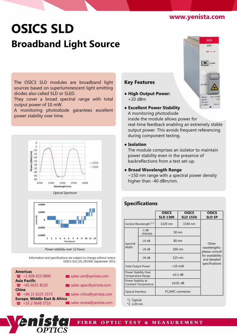
OSICS SLD
The OSICS SLD modules are broadband light
sources based on superluminescent light emitting
diodes also called SLD or SLED.
They cover a broad spectral range with total
output power of 10 mW.
A monitoring photodiode garantees excellent
power stability over time.
Broadband Light Source
Key Features
● Excellent Power Stability
A monitoring photodiode
inside the module allows power for
real-time feedback enabling an extremely stable
output power. This avoids frequent referencing
during component testing.
● Broad Wavelength Range
~150 nm range with a spectral power density
higher than -40 dBm/nm.
● High Output Power:
+10 dBm
Optical Spectrum
Power stability over 12 hours
FC/APC connector
±0.01 dB
±0.1 dB
+10 mW
125 nm
100 nm
50 nm
Optical Interface
Power Stability Over
Temperature Range
Power Stability at
Constant Temperature
Spectral
Width
Total Output Power
80 nm
OSICS
SLD 1300
Central Wavelength*1,*2 1320 nm
-3 dB
(FWHM)
-10 dB
-20 dB
-30 dB
1540 nm
OSICS
SLD 1550
OSICS
SLD SP
Other
wavelengths:
please consult
for availability
and detailed
specifications
*1. Typical.
*2. ±20 nm.
Specifications
+65 6631 8520 [email protected]
+33 2 9648 3716 [email protected]
+86 21 6225 3573 [email protected]
[email protected]+1 609 423 0890
China
Asia Pacific
Americas
Europe, Middle East & Africa
● Isolation
The module comprises an isolator to maintain
power stability even in the presence of
backreflections from a test set-up.

OSICS FBLFull-Band Tunable Laser
The OSICS FBL is a unique tunable laser system that
covers the full telecom wavelength range, from
1260 nm to 1680 nm, in a single unit. The output is SSE
free with power of at least 0 dBm. The system consists
of four OSICS T100 modules integrated with an optical
switch. The single fiber output combined with Yenista's
proven OSICS platform means reliable, fully automated
test systems can be easily established.
Applications
1260 nm to 1680 nm
User Friendly Control Interface
Proven Reliability
All telecom wavelength bands (O, E, S, C, L and U) are
supported with a single fiber output. This is particularly
useful for silicon photonics, CWDM, PON and photonic
crystal characterization. It also allows automated testing
over the entire wavelength range.
The front panel interface is a real benefit in a laboratory
environment. The display shows, at a glance, the
settings of all installed modules and alleviates the need
for a separate control PC.
The OSICS platform and the opto-mechanics in the full-
band tunable laser are well established and widely used
in critical test environments in the telecoms industry.
Recent innovations have optimised performance whilst
maintaining the design of the critical kinematic chain
which is essential for reliable operation.
Telecom System & Component Testing The ultra-low SSE is a big advantage and enables
repeatable high dynamic range measurements.
Production environments benefit from the proven
reliability and easy to use interface.
Material Characterization Ideal for photonic crystal and fiber characterization.
Sensors & SpectroscopyThe wavelength can be modulated to scan across a gas
line for gas sensor research and spectroscopy.
Scientific Research & DevelopmentExtensive input and output ports provide added
flexibility and satisfy a wide range of test requirements.
90 dB / 0.1 nm Ultra-low Optical Noise Yenista's unique T100 cavity eliminates the broadband
spontaneous emission (SSE) that is normally present in
an external cavity laser's output. The OSICS T100 has
one of the lowest figures of merit for SSE of any
tunable laser on the market and gives a dramatic
improvement in a measurement's dynamic range.
www.yenista.com
Modular FlexibilityThe modular design means a partial system can be
purchased initially. This can then be upgraded at a later
date thus staggering capital expenditure. The system is
also compatible with legacy OSICS modules. These can
be integrated into the system if available.
Stable OutputThe OSICS FBL has benefited from Yenista's experience
in developing high performance tunable lasers. The
optical design ensures both output power and
wavelength are stable with excellent repeatability.
Key Features

Specifications
The OSICS Full Band Laser uses five slots of
the OSICS mainframe. The three spare slots
can be used to support additional
modules. These can be attenuators or
switches to create a complete test system,
or additonal lasers and light sources. The
OSICS mainframe will identify the modules
installed and display the setting for each
module on the front panel. All modules can
be controlled from the front panel or
through the GPIB or RS-232C interfaces.
*1: At constant temperature.
*2: Measured at 0 dBm output power.
*3: Not calibrated above 1660 nm.
Information and specifications are subject to change without notice.
OSICS FBL-DS-201309, September 2013.
*4: Measured at 100 MHz.
*5: Includes suppression of the output of non-selected laser modules.
*6: Measured over a 0.1 nm bandwidth ±1nm from the signal.
*7: Tested & validated with National Instruments GPIB Board.
Wavelength
Power
Spectrum
Interfaces
Operating Conditions
Size
Tuning range
Setting resolution
Absolute accuracy
Repeatability
Stability*1, *2
Tuning speed
Output power over full tuning range
Analogue modulation
Digital modulation
Relative intensity noise*2, *4
Side mode suppression ratio*5
Signal to source spontaneous emission ratio*6
Output fiber type
Output connector
Output isolation
Control
Temperature range
Power supply
Laser safety classification
Dimensions (W x D x H)
Weight
Spectral width (FWHM)
Accuracy*3
1260 to 1680 nm
0.01 nm
±0.2 nm
± 0.01 nm typical
±0.01 nm / h (±0.01 nm / 24 h typical)
10 nm/s
> 0 dBm
±0.2 dB
±0.01 dB / h (±0.01 dB / 24 h typical)
150 Hz to 200 MHz (external)
500 Hz to 1 MHz (internal & external)
–145 dB/Hz typical
>45 dB
>90 dB / 0.1nm typical
Coherence Control off: 50 kHz typicalCoherence Control on: >100 MHz
SMF or PMF (option)
FC/APC
35 dB
Front panel, RS-232C, GPIB (IEEE-488.2*7)
+15 to +30°C (+59° to +86°F)
100 to 240 V a.c. / 50 to 60 Hz / 60W
Class 1M
448 x 370 x 133 mm
13.1 kg
www.yenista.com
Stability*1, *2
+65 6631 8520 [email protected]
+33 2 9648 3716 [email protected]
+86 21 6225 3573 [email protected]
[email protected]+1 609 423 0890
China
Asia Pacific
Americas
Europe, Middle East & Africa
Additional OSICS Modules
All specifications are given after 60 minutes warm-up, and apply for wavelengths not equal to any water absorption line.
T100
TLS-50
TLS-AG
DFB
ATN HP
BKR
SWT
SLD
Low noise, external cavity laser
ITU grid locked tunable laser
Tunable laser for coherent systems
Distributed feedback laser
Variable optical attenuator
Variable optical backreflector
A variety of optical switches
Superluminescent light source

www.yenista.com
Information and specifications are subject to change without notice.
OSICS-Accessories_DS_201309, September 2013.
-
Yenista provides various accessories for the
OSICS multifunction platform.
Jumpers
OSICS Accessories
+65 6631 8520 [email protected]
+33 2 9648 3716 [email protected]
+86 21 6225 3573 [email protected]
[email protected]+1 609 423 0890
China
Asia Pacific
Americas
Europe, Middle East & Africa
SMF and PMF jumpers are available with FC/PC,
FC/APC, SC/PC and SC/APC connectors. They are
compatible with the instruments.
Cover Plates
Cover plates are available for mounting onto
empty OSICS module slots for electrical safety.
Handles
Handles are available for mounting an OSICS
mainframe into a 19-inch rack.
The handles can also be used for carrying the
instrument.
0.3 meters long SMF jumpers with FC/APC
connectors on both sides are adapted to make
connections between modules located in the
same OSICS mainframe. They are well suited for
building compact test systems such as the OSICS
Full Band Laser.
2.0 meters long SMF and PMF (PM13 and PM15)
jumpers are also available:
Special OSICS Jumpers
Others Jumpers
● FC/APC-SC/APC
● FC/PC-SC/PC
● FC/APC-SC/PC
● FC/PC-SC/APC
● FC/APC-FC/APC
● FC/PC-FC/PC
● FC/APC-FC/PC