Embed Size (px)
Citation preview

OSH and the 400,000Volt Van de Graaf Generator
& More
By Frederick W. Graff
Copyright@ Frederick Graff 2012

2 Frederick W. Graff©2008 | Graff Generators
~~~~TABLE OF CONTENTSTABLE OF CONTENTSTABLE OF CONTENTSTABLE OF CONTENTS~~~~
Parts of a VDG and How it Works…………………….. 3
Choosing the VDG size……………………………............. 5
Tower Construction…………………………………………… 7
Roller & Belt Construction…………………………………. 12
Tower Base ………………………………………………………. 7
Base Design & Motor………………………………………... 17
Discharge Sphere……..……………………………………….. 20
Support System…………………………………………………. 22
Spraying a Charge…………..…………………………………. 24
Videos & Extra Resources……………….…………………. 28
400kv & 700kv Operation Instruction………………… 29
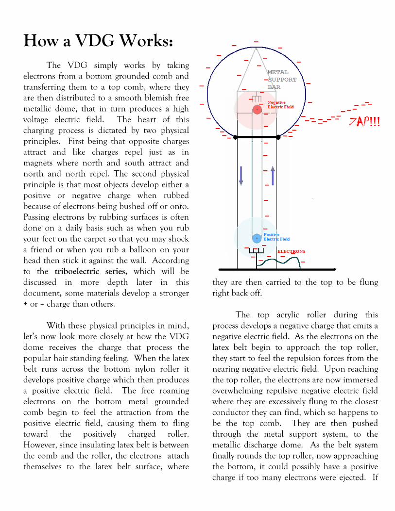
How a VDG Works:
The VDG simply works by taking
electrons from a bottom grounded comb and
transferring them to a top comb, where they
are then distributed to a smooth blemish free
metallic dome, that in turn produces a high
voltage electric field. The heart of this
charging process is dictated by two physical
principles. First being that opposite charges
attract and like charges repel just as in
magnets where north and south attract and
north and north repel. The second physical
principle is that most objects develop either a
positive or negative charge when rubbed
because of electrons being bushed off or onto.
Passing electrons by rubbing surfaces is often
done on a daily basis such as when you rub
your feet on the carpet so that you may shock
a friend or when you rub a balloon on your
head then stick it against the wall. According
to the triboelectric series, which will be
discussed in more depth later in this
document, some materials develop a stronger
+ or – charge than others.
With these physical principles in mind,
let’s now look more closely at how the VDG
dome receives the charge that process the
popular hair standing feeling. When the latex
belt runs across the bottom nylon roller it
develops positive charge which then produces
a positive electric field. The free roaming
electrons on the bottom metal grounded
comb begin to feel the attraction from the
positive electric field, causing them to fling
toward the positively charged roller.
However, since insulating latex belt is between
the comb and the roller, the electrons attach
themselves to the latex belt surface, where
they are then carried to the top to be flung
right back off.
The top acrylic roller during this
process develops a negative charge that emits a
negative electric field. As the electrons on the
latex belt begin to approach the top roller,
they start to feel the repulsion forces from the
nearing negative electric field. Upon reaching
the top roller, the electrons are now immersed
overwhelming repulsive negative electric field
where they are excessively flung to the closest
conductor they can find, which so happens to
be the top comb. They are then pushed
through the metal support system, to the
metallic discharge dome. As the belt system
finally rounds the top roller, now approaching
the bottom, it could possibly have a positive
charge if too many electrons were ejected. If
4 Frederick W. Graff©2008 | Graff Generators
this is the case, as in the VDG you are about
to build, its just going to run all the stronger!
To cover one last aspect of the VDG,
the dome accounts for at least 80% the
generator’s final output voltage. So that a
maximum voltage can be achieved, it is
essential to understand conceptually how the
electrons interact with the metal sphere.
Once the electrons make it to the dome, they
are now roaming around and cramming
against each other due to their individual
electric fields. Essentially they are looking for
a way out, which consist of any edge or point
on the surface that offers a path of least
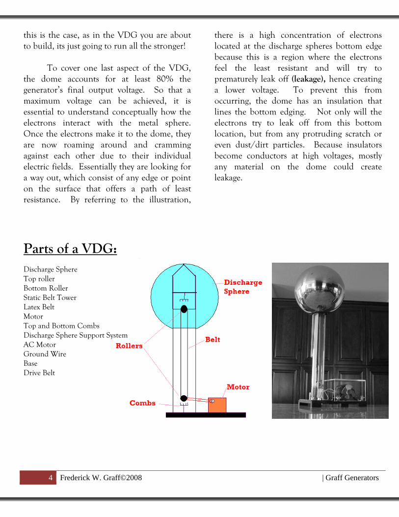
resistance. By referring to the illustration,
there is a high concentration of electrons
located at the discharge spheres bottom edge
because this is a region where the electrons
feel the least resistant and will try to
prematurely leak off (leakage), hence creating
a lower voltage. To prevent this from
occurring, the dome has an insulation that
lines the bottom edging. Not only will the
electrons try to leak off from this bottom
location, but from any protruding scratch or
even dust/dirt particles. Because insulators
become conductors at high voltages, mostly
any material on the dome could create
leakage.
Parts of a VDG:
Discharge Sphere
Top roller
Bottom Roller
Static Belt Tower
Latex Belt
Motor
Top and Bottom Combs
Discharge Sphere Support System
AC Motor
Ground Wire
Base
Drive Belt

Choosing the VDG
Size and Initiating the
Building Process
When designing a VDG there are a
variety of routes that one may take relative to
the VDG’s size, dive system, static materials,
dome capacitance, aesthetics and so on. To
many experimenter’s surprise, the final output
voltage of a VDG is dictated not by the RPMs
or even static material (though these are very
crucial aspects), but through size of the dome
or better yet, the dome capacitance. Using
the break down voltage of air and general
capacitance equations for a dome, it may be
analytically found that for every 1 inch the
dome’s radius increases, the output voltage
increases by 70,000 volts. One the other side,
if the belt and rollers do not operate
efficiently enough, this maximum potential
cannot be achieved.
Some builders may say the bigger the
better and right so, but before making such
costly leaps, lets first consider a few things.
For starters, this is a low current high voltage
devise that is meant to be tangible to the
operator. This is not a Tesla Coil. If you the
designer are looking for large arcs, then build
a coil using two of the largest NST’s and cap
banks you can find. In the long run though, I
promise you will find a VDG more intriguing
considering that you can physically handle
and manipulate a piercing 400,000KV electric
field.
To help us consider the VDG size to
build, larger VDGs are obviously more
exhilarating then the smaller ones and of
course do have draw backs. First as stated
above, you do want to be able to touch these.
I have found that anything over about 1.2MV
is almost too painful to handle not to
mention unsafe, so I would limit any design
to a 30 inch (1.05MV) dome but no less than
12 inches (320,000V).
Smaller VDG’s have not shown to have
any type of true design constraints unlike the
larger and more powerful units. Larger units
do need to operate at greater electrical
currents because of the larger dome that is
constantly being replenished with electrons.
The design constraint on the larger units
appears in the static belts system because as
the belt goes up with a negative charge the
other side of the belt comes down with a
positive which causes the two belts to flex into
each other and furthermore potentially
invokes harmonics in the system. Therefore,
larger systems will need much tighter belts to
6 Frederick W. Graff©2008 | Graff Generators
avoid these deflections, which means more
costly bearings and possibly using neoprene as
the static belt, which does not deliver the
same amount of charge as a latex belt nor
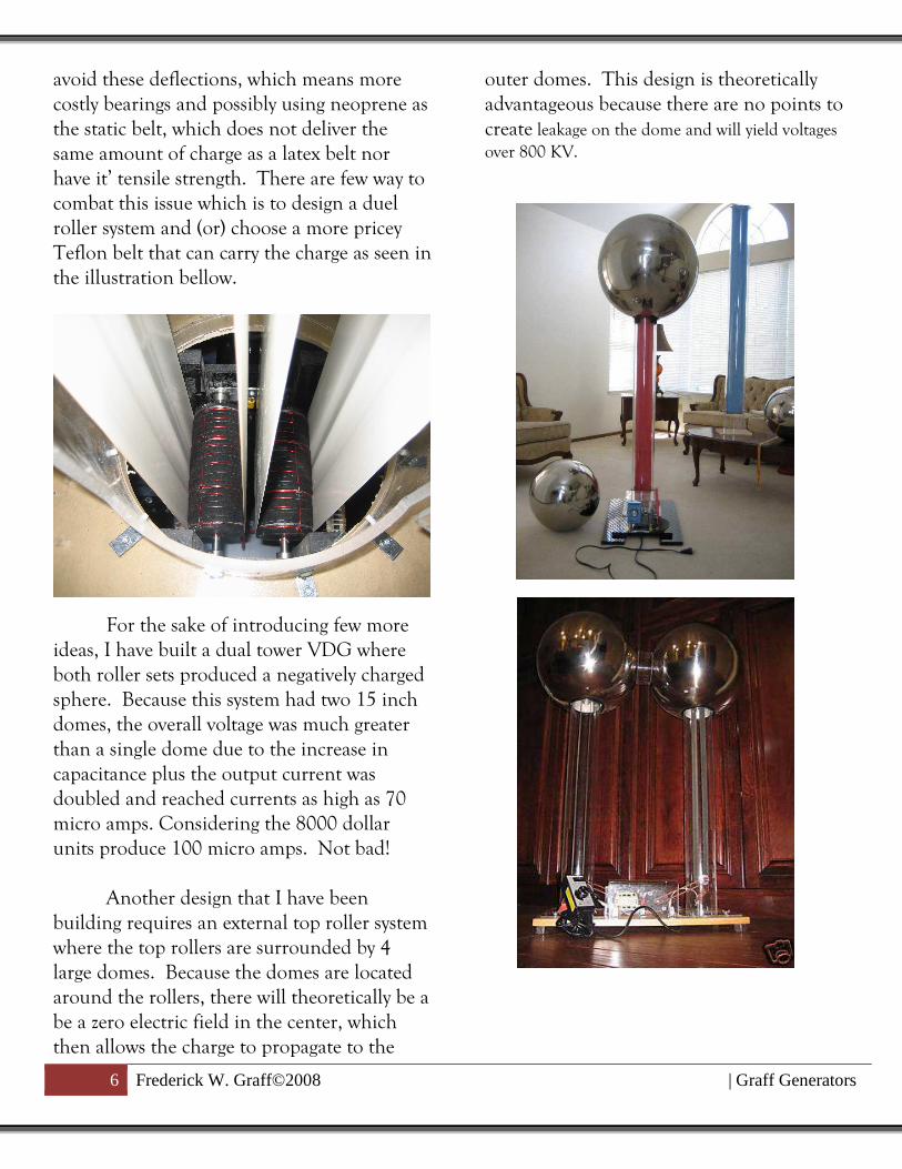
have it’ tensile strength. There are few way to
combat this issue which is to design a duel
roller system and (or) choose a more pricey
Teflon belt that can carry the charge as seen in
the illustration bellow.
For the sake of introducing few more
ideas, I have built a dual tower VDG where
both roller sets produced a negatively charged
sphere. Because this system had two 15 inch
domes, the overall voltage was much greater
than a single dome due to the increase in
capacitance plus the output current was
doubled and reached currents as high as 70
micro amps. Considering the 8000 dollar
units produce 100 micro amps. Not bad!
Another design that I have been
building requires an external top roller system
where the top rollers are surrounded by 4
large domes. Because the domes are located
around the rollers, there will theoretically be a
be a zero electric field in the center, which
then allows the charge to propagate to the
outer domes. This design is theoretically
advantageous because there are no points to
create leakage on the dome and will yield voltages over 800 KV.
Tower Construction:
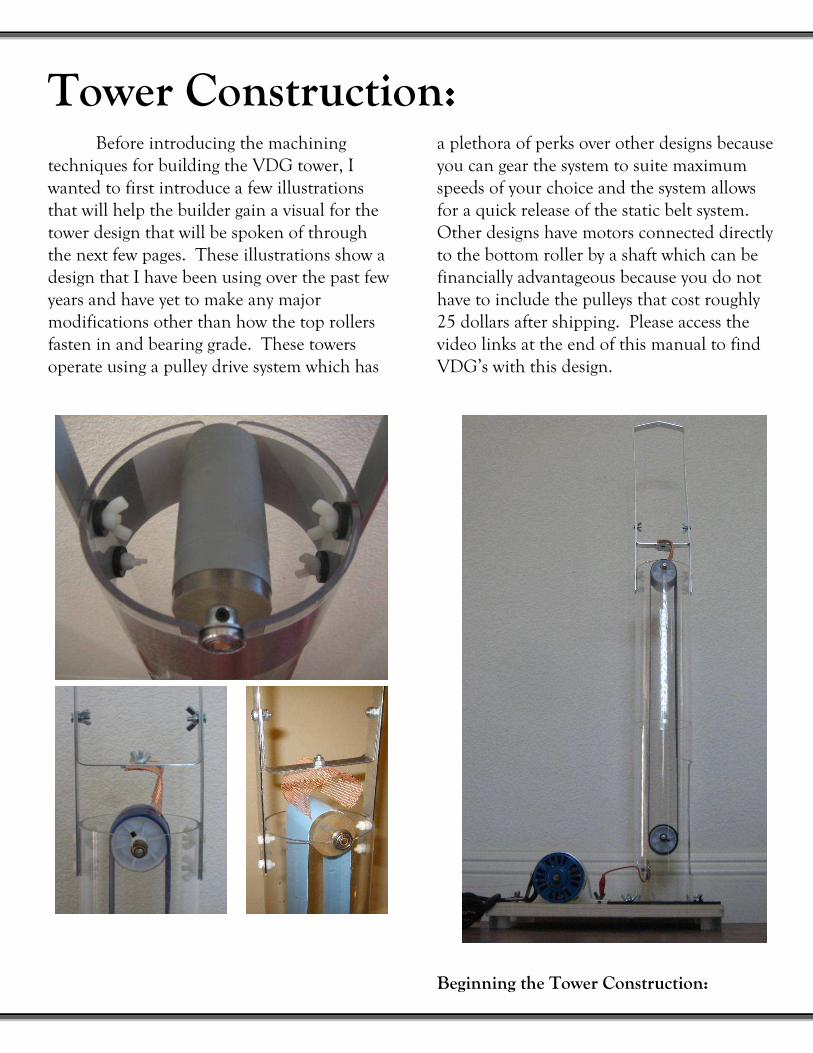
Before introducing the machining
techniques for building the VDG tower, I
wanted to first introduce a few illustrations
that will help the builder gain a visual for the
tower design that will be spoken of through
the next few pages. These illustrations show a
design that I have been using over the past few
years and have yet to make any major
modifications other than how the top rollers
fasten in and bearing grade. These towers
operate using a pulley drive system which has
a plethora of perks over other designs because
you can gear the system to suite maximum
speeds of your choice and the system allows
for a quick release of the static belt system.
Other designs have motors connected directly
to the bottom roller by a shaft which can be
financially advantageous because you do not
have to include the pulleys that cost roughly
25 dollars after shipping. Please access the
video links at the end of this manual to find
VDG’s with this design.
Beginning the Tower Construction:
8 Frederick W. Graff©2008 | Graff Generators
Regardless if you are pursuing the
exclusively acrylic or plastic of your choice, the
initial steps to machining the tower are
identical. Through the course of this manual,
you will find additional instruction regarding
machining techniques for the acrylic design.
Furthermore, if you choose to deviate from
the design, I highly encourage everybody to
first thoroughly read through this guidebook
because there are crucial subtleties that must
be incorporated to insure an efficiently
operating VDG.
For my 400KV unit, I use a 4 inch OD
tube that is 2 feet long which seem to be in
good proportion. If you are using a 20 or 22
inch dome I would go with at least a 5 inch
OD tube that is a minimum of 3 feet long. A
30 inch dome will need about a 6-7 inch tube
and should be 4 to 6 feet long. Now that we
have a proper tube size, let’s start prepping the
material and making our first measurements.
Step 1: Squaring the Tower Ends
Despite the base that you choose, either
a PVC insert or an acrylic sheet, the ends of
the tubing must be square so that the top
rollers run perfectly horizontal and the base
sit perfectly perpendicular on the base. To
square the edges you will need either a 10” or
12” chop saw that contains a blade used for
cutting plywood. To square the ends, simply
trim a fraction of an inch off of each end.
When finished, place the tower on a flat
surface so insure that the tower stands
perfectly perpendicular. Repeat this process
for both ends and then sand the ends using
80 grit sand paper.
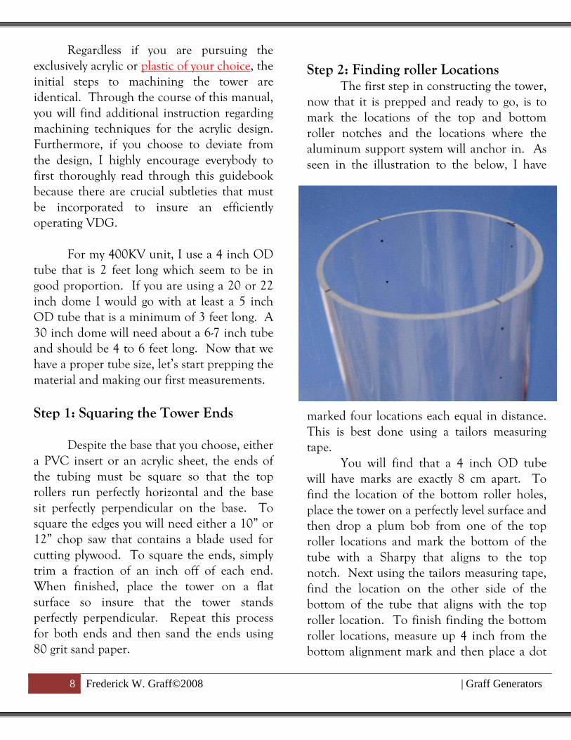
Step 2: Finding roller Locations The first step in constructing the tower,
now that it is prepped and ready to go, is to
mark the locations of the top and bottom
roller notches and the locations where the
aluminum support system will anchor in. As
seen in the illustration to the below, I have
marked four locations each equal in distance.
This is best done using a tailors measuring
tape.
You will find that a 4 inch OD tube
will have marks are exactly 8 cm apart. To
find the location of the bottom roller holes,
place the tower on a perfectly level surface and
then drop a plum bob from one of the top
roller locations and mark the bottom of the
tube with a Sharpy that aligns to the top
notch. Next using the tailors measuring tape,
find the location on the other side of the
bottom of the tube that aligns with the top
roller location. To finish finding the bottom
roller locations, measure up 4 inch from the
bottom alignment mark and then place a dot

9 Frederick W. Graff©2008 | Graff Generators
for each side. To find the top roller holes,
just measure down a half inch from each
roller location and place a dot.
The aluminum dome support system
holes locations are found from the other two
notches. These holes are 1 inch apart and the
top hole a ½ inch down from the top of the
tower. For those who are pursuing the larger
VDG, these locations should be between 1.5
to 2.5 inches apart.
All holes should first be drilling with a
small pilot bit. After the pilot holes are
drilled, finish the roller holes location using a
3/8 bit only if you are using the flanged
sintered bearings. The aluminum holes
should be drilled with an 11/64 bit or larger.
To drill acrylic with the larger bits, run the drill on reverse and allow it to melt through otherwise you will crack the acrylic.
The top roller notch, as seen in the
illustration to the left, was machined by first
drilling the hole and then grinding out the
remaining material using a Dremel. This may
also be done using a file or smaller drill.
Step 3: Machining the Bottom Roller
Entrance Hole The illustration on the next page
shows the bottom roller entrance locations. I
have enjoyed this design because of how
efficient it both braces the bottom roller and
allows for a very quick belt adjustment or
maintenance. Other designs have the bottom
rollers fastened into the base which can be
time consuming when any type of
maintenance is at hand, especially since VDG
belts should be cleaned about every two hours
of use.
To machine the bottom entrance hole,
first do not be shy to design the entrance hole
to extend upwards a significant distance as
seen in the photo. Even with the much larger
units I have made, this design had worked
perfectly. Secondly, be sure to allow the
opening to extend enough circumferentially
such that you can fit your hand inside because
you will need to be able to reach you hand up
inside to grab the belt.

10 Frederick W. Graff©2008 | Graff Generators
The best way to initiate the machining
once you have finalized your roller opening
dimensions, it to trace the opening using a
straight edge and dry erase Sharpy. Next,
carve the tracing with a Dremel Rotozip and
then smooth the surface with 80 grit sand
paper. When carving, make sure to cut the
bottom hole entrance notch so that it is
curving downwards otherwise the roller will
not hold.
The final step in preparing the tower is
to fasten it to the base. The photos on the
next page show two different strategies to
attaching the tower to the base. If you choose
to fasten an acrylic tower to an acrylic base
you will need Weld On Acrylic Cement and
the applicator that is sold through Tap Plastic
or various Ebay sources. If you choose not to
use the acrylic cement, super glue works
almost as well plus you do not have to deal
with the extremely caustic odors produced by
the Weld On cement. The other illustrations
use a PVC flange that may be purchased at
OSH or Home Depot for about 7 dollars.
The PVC flange will need a different diameter
for acrylic tubing for those who are trying to
go with the all acrylic design.
If you choose the all acrylic design,
there is a very simple way to center the tower
to the acrylic tower base. First, trace a line
through the center of the acrylic base as seen
in the illustration bellow. Next, place the
tower on the acrylic base and align the bottom
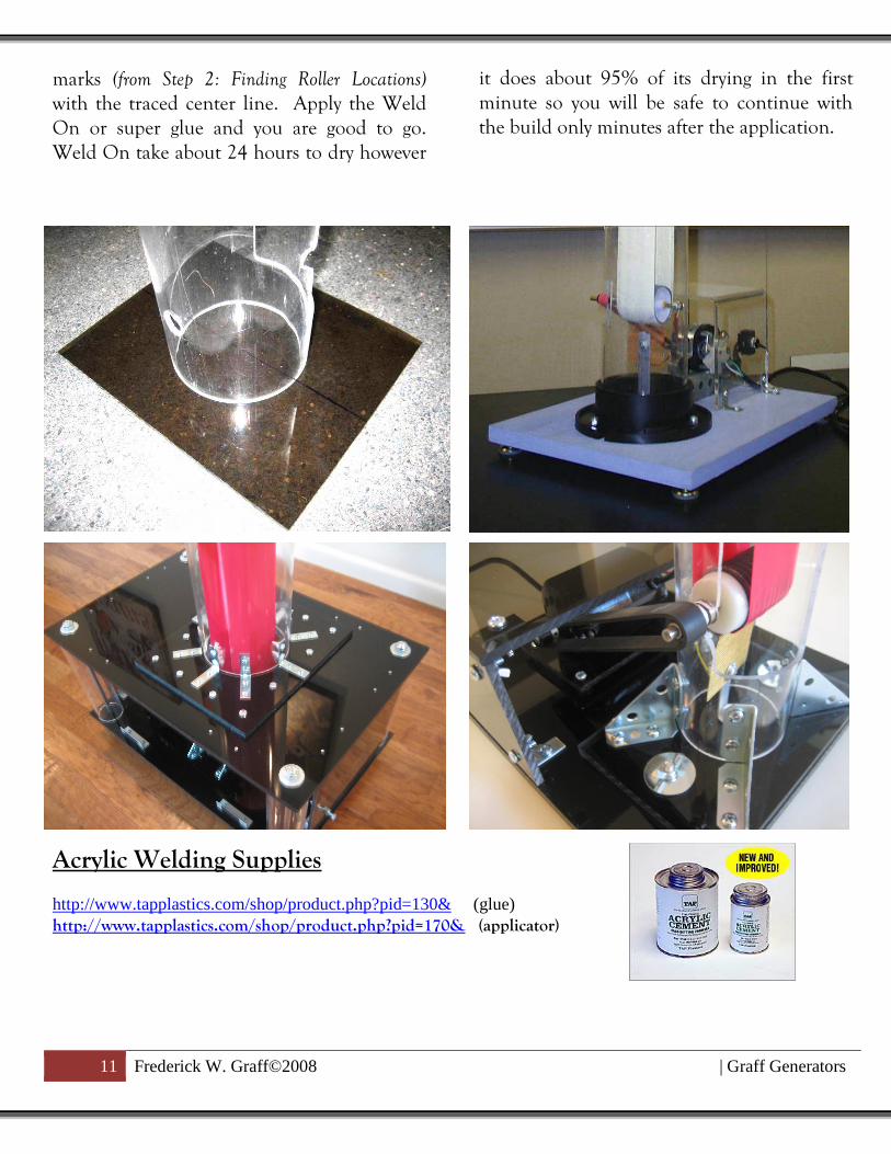
11 Frederick W. Graff©2008 | Graff Generators
marks (from Step 2: Finding Roller Locations)
with the traced center line. Apply the Weld
On or super glue and you are good to go.
Weld On take about 24 hours to dry however
it does about 95% of its drying in the first
minute so you will be safe to continue with
the build only minutes after the application.
Acrylic Welding Supplies http://www.tapplastics.com/shop/product.php?pid=130& (glue) http://www.tapplastics.com/shop/product.php?pid=170& (applicator)
12 Frederick W. Graff©2008 | Graff Generators
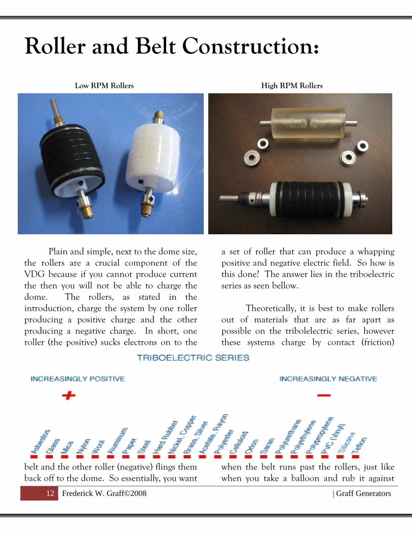
Roller and Belt Construction: Low RPM Rollers High RPM Rollers
Plain and simple, next to the dome size,
the rollers are a crucial component of the
VDG because if you cannot produce current
the then you will not be able to charge the
dome. The rollers, as stated in the
introduction, charge the system by one roller
producing a positive charge and the other
producing a negative charge. In short, one
roller (the positive) sucks electrons on to the
belt and the other roller (negative) flings them
back off to the dome. So essentially, you want
a set of roller that can produce a whapping
positive and negative electric field. So how is
this done? The answer lies in the triboelectric
series as seen bellow.
Theoretically, it is best to make rollers
out of materials that are as far apart as
possible on the tribolelectric series, however
these systems charge by contact (friction)
when the belt runs past the rollers, just like
when you take a balloon and rub it against

13 Frederick W. Graff©2008 | Graff Generators
your head. Therefore, the ideal materials are
the one that have both high friction surfaces
and lie very far apart on the triobo chart. For
example, I have made a high RPM roller set
out of nylon wrap in wool (positive) to give it
a rough surface and acrylic painted with a
high friction silicon coating called Pliobond
(negative). The low RPM set, as seen the
upper illustration to the left, is also made
from nylon wrap in wool and the other with
nylon wrapped in packing tape. Other
combinations that I would recommend are
Nylon and Teflon, Nylon and PVC, and
Nylon and Delrin.
High RPM and XL VDG Rollers :
Before we dive into the roller
construction for the low budget driven VDG,
let’s first answer a few questions for those who
are building the larger and higher RPM
systems. First, when constructing higher rpm
systems, you have to either use cast materials
or have a machinist turn the material which is
very costly. I would purchase 1.5 – 2 inch OD
cast materials from any one of the on-line
resources and then have a local machinist
punch the center holes, unless that is, you
have a lathe of your own. For those who
don’t, I would purchase a six pack of the
machinist favorite beverage and kindly ask
him if he would be willing to take a few
minutes out to punch a few center holes for
you. Otherwise, he will say I charge 60 dollars
per hour with the first hour to set up and plus
time to machine. The honest truth is that it
takes 1 minutes to place the quarter inch bit
in the machine and about 4 minutes to finish
the job with a small coffee break buried in the
middle. Go for the six pack! To further help
reduce machining cost, you do not have to
crown the rollers. If you notice on my higher
rpm rollers, the wool is centered on the roller.
This placement gives the belt a lip to ride on.
If you would like to create lip on the top
acrylic roller, wrap packing tape around the
very center as seen in the illustration bellow.
This is a bonus because packing tape has
incredible electrostatic properties that will
produce the hair standing charge that you are
designing for.
Relative to the bigger and better VDG
enthusiast, if you are using a tower that is 4
feet or taller you will need rollers at least 2
inch in diameter to alleviate the attraction
between the belts. This will also allow you to
run a greater belts speeds plus help eliminate
unwanted harmonics that develop at higher
RPMs. Another very common design flaw
that will create harmonics in the belt would
be rollers that have been over crowned.
When crowning the rollers never use more
than a 10 degree crown otherwise the belts
will pass through too much of a deflection
14 Frederick W. Graff©2008 | Graff Generators
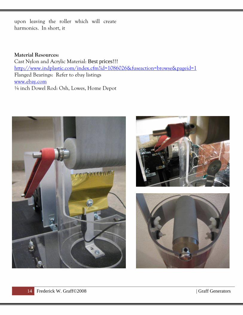
upon leaving the roller which will create
harmonics. In short, it
Material Resources:
Cast Nylon and Acrylic Material: Best prices!!! http://www.indplastic.com/index.cfm?id=1086026&fuseaction=browse&pageid=1
Flanged Bearings: Refer to ebay listings
www.ebay.com
¼ inch Dowel Rod: Osh, Lowes, Home Depot

15 Frederick W. Graff©2008 | Graff Generators
Low RPM Roller Construction:
As described, the top and bottom roller
may be easily constructed out of 1.5 to 2” OD
stock rod along with proper machining. This
technique is sufficient for RPM’s greater than
2500. If you choose to run less than 2500, a
much more simple design may be pursued by
using nylon caster wheels which may be
purchase at any hardware store or Wal-Mart
being the cheapest at 1.99 each. The Nylon
caster wheels come in a wide variety of
different sizes and materials, therefore make
sure you choose the white larger caster wheels
that are about 2 inches in diameter. To
prepare these rollers you will have to first
remove the brass dowel pins that pass through
them by drilling out the riveted ends.
With the brass pins removed, you may
now place in the axles. I have used the
lengths of 4.5 inches for the top axle and 5.25
inches for the bottom. The bottom axle is
one inch larger because of the drive pulley
that is placed on it. Because the ID of the
caster wheel is slightly larger than the ¼ stock
rod, you will need to wrap the axle with metal
tape at the location the roller sits on. The
illustration bellow shows a picture of the
bottom roller axle (5.25 inches). The roller
may be fastened to the axle few ways, the first
of which is to use 2000lb two part epoxy. The
second way, being more efficient is to drill
holes through the ends of the roller and then
run set pins through them the press against
the axle.
The last step before inserting the bearings,
flat belt pulley, and shaft collar, is to coat the
bottom roller with your color of choice100%
wool felt. To adhere the felt, first cut the
cloth to shape and then super glue it to the
nylon roller using a brush on applicator.
When doing so, use the superglue sparing as
the glue itself will yield a negative charge
when rubbed. You will know you there has
been applied too much if the wool develop a
white milky stain on the outside. Next, wrap
the wool using nylon fishing string to further
secure the felt.

16 Frederick W. Graff©2008 | Graff Generators
After the ¼ inch OD brass dowel rods
have been inserted as axles, it is now time to
include the bearings, shaft collar, and flat belt
pulley and so here is where things may go
wrong. If you use unsealed flanged ball
bearings or low quality sealed flanged
bearings, the VDG’s electric fields will suck
every ounce of oil from them which will both
destroy the bearings and turn off the VDG,
plus crack all of the acrylic bearing holes due
to a reaction with the oil. Oil and VDG’s do
not mix!
Materials Resources:
1) Caster Wheel – Lowe’s, OSH, Home Depot, Walmart (4 to 8 dollars for 2 large caster)
http://www.idealtruevalue.com/servlet/the-63955/Detail
2) 2500lb two part epoxy – Lowe’s, OSH, HomeDepot (4 dollars) 3) ¼ Flanged Bearings: OSH http://www.sdp-si.com/index.asp (1 dollar at web site)
4) ¼ inch ID Shaft Collar: OSH or http://www.sdp-si.com/index.asp
5) Set pins for rollers: OSH 6) ¼ inch dowel rod: OSH
7) 100% wool felt: http://www.twiningthread.com/Wool-Felt01.html

17 Frederick W. Graff©2008 | Graff Generators
Additional Roller Designs:

18 Frederick W. Graff©2008 | Graff Generators
Base Design Ideas & Choosing the Right Motor:
A huge misconception about Van de
Graaf Generators is that you do not need a lot
of horse power to drive a VDG system. Even
my largest generators only use fractional horse
powered motors. If I chose to, I could have
even ran my 1 MV system off of a Dayton
1/15Hp motor, the same that I use for my
mid size 700KV system. A second item that is
often flawed is that if your generator has an
efficient roller set, then the VDG will not
need to run over 2500 RPM. Of the motors I
have come across, I would highly advise the
1/15hp 5000 RPM Dayton (part number
2m066) because it can operated with an
external router
speed control and
it has more than
enough power to
run most size
systems.
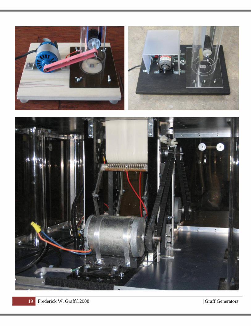
The base design that I have chosen over
the past 5 years uses a drive belt as seen in the
illustrations. This route may be more
advantageous than directly connecting a drive
shaft from the motor to the roller because it
allows for gearing the drive system and allows
for easy belt changes. For those who own a
commercial VDG know the frustration of belt
changes considering how often belts need
replaced and cleaned. To allow flexibility in
the design, I have used Narco rubber bands
for the drive belt as appose to a neoprene
timing belt which require immense precision
when anchoring the motor unless an
adjustable motor mount is to be used. In
addition, I have also used dirt devil 12
sweeper belts for my larger 700KV VDG
model. Please use the following illustrations
to help ferment a creative drive system for
your VDG. These illustrations show a variety
of models that I have built over the past few
years.
19 Frederick W. Graff©2008 | Graff Generators

20 Frederick W. Graff©2008 | Graff Generators
Advised Motor and Drive Component Resources:
1) http://www.sciplus.com/
(Variety of motors and great prices)
2) http://www.electricmotorwarehouse.com/Dayton_AC_DC_Motors.htm
(Dayton motor as seen in illustrations\
3) http://www.surpluscenter.com/electric.asp
(Variety of motors and great prices)
4) http://search.harborfreight.com/cpisearch/web/search.do?keyword=speed+control
(Speed control for 1/15Hp 5000 rpm Dayton AD/DC motor)
5) http://sdp-si.com/
(Timing Belts, flat belt pulleys, Gears, Etc…)
21 Frederick W. Graff©2008 | Graff Generators
CONSTRUCTING A DISCHARGE SPHERE:
When making a discharge sphere, your main goal is to prevent leakage which is the
premature discharge of electrons from the sphere. Leakage is primarily caused by pointy
conductive edges, therefore your job is to construct a dome that has a very smooth surface. To
construct the dome, one may go about two different ways, the frugal route or the expensive route.
I prefer the more expensive route because it is more efficient
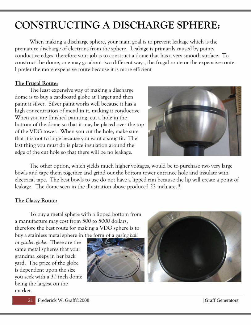
The Frugal Route:
The least expensive way of making a discharge
dome is to buy a cardboard globe at Target and then
paint it silver. Silver paint works well because it has a
high concentration of metal in it, making it conductive.
When you are finished painting, cut a hole in the
bottom of the dome so that it may be placed over the top
of the VDG tower. When you cut the hole, make sure
that it is not to large because you want a snug fit. The
last thing you must do is place insulation around the
edge of the cut hole so that there will be no leakage.
The other option, which yields much higher voltages, would be to purchase two very large
bowls and tape them together and grind out the bottom tower entrance hole and insulate with
electrical tape. The best bowls to use do not have a lipped rim because the lip will create a point of
leakage. The dome seen in the illustration above produced 22 inch arcs!!!
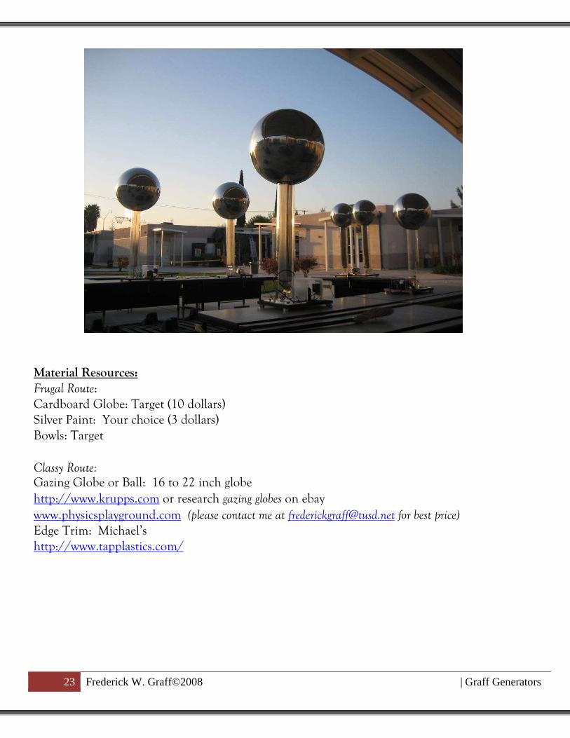
The Classy Route:
To buy a metal sphere with a lipped bottom from
a manufacture may cost from 500 to 5000 dollars,
therefore the best route for making a VDG sphere is to
buy a stainless metal sphere in the form of a gazing ball
or garden globe. These are the
same metal spheres that your
grandma keeps in her back
yard. The price of the globe
is dependent upon the size
you seek with a 30 inch dome
being the largest on the
market.

22 Frederick W. Graff©2008 | Graff Generators
To begin construction, mark the size of the hole you wish to make. Next, using a Dremel
with a metal grinding cut off wheel, slowly cut out the hole and then grid off any burs. Lastly,
insulate the edge with your choice of insulation of which I prefer to use edge trim that may be
purchased at Tap Plastic or Michael’s.
Another technique of insulating the
bottom of the sphere would be to use a door edge
trim however, in order to do so, the sphere must
have a tight fit around the VDG tower. In this
process, as seen in the illustration to the right, I
made a tight fit with the dome and then the edge
trim is wrapped directly around the tower so that
the tube rest against the edging with a slight
amount of pressure. Lastly, to secure the edging,
I wrapped black electrical tape around it. Of the
two techniques listed, I have found both to work
just the same.
If you wish to significantly increase the
charging capacity of the dome, further wrap the
bottom with electrical tape to prevent leakage.
Proceed with absolute caution when testing!!!
23 Frederick W. Graff©2008 | Graff Generators
Material Resources:
Frugal Route:
Cardboard Globe: Target (10 dollars)
Silver Paint: Your choice (3 dollars)
Bowls: Target
Classy Route:
Gazing Globe or Ball: 16 to 22 inch globe
http://www.krupps.com or research gazing globes on ebay
www.physicsplayground.com (please contact me at [email protected] for best price)
Edge Trim: Michael’s
http://www.tapplastics.com/

24 Frederick W. Graff©2008 | Graff Generators
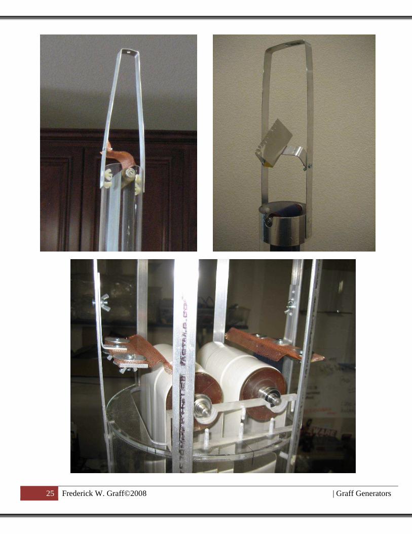
CONSTRUCTING A DISCHARGE SPHERE
SUPPORT SYSTEM:
The support system’s main purpose it
to hold the discharge sphere and combs in an
insulated environment. One of the biggest
mistakes that I made on my first VDG was
setting the support system on the inside of the
tower. The reason why this hindered the
design was that the charge was leaking back to
the belt. As seen in the illustrations bellow,
the aluminum bar stock is placed on the
outside of the tower with nylon hardware use
for bracing to help further insulate the system.
A wide variety of materials may be used for
the support system, with the most pragmatic
being aluminum due to its malleability. I
have yet to change my design for the support
system because of its functionality. The top of
the support system may be tapped for the bolt
used to stabilize the dome and the swinging
comb arm makes the static belt very accessible.
For the Combs, I highly recommend
wire form over any type of rigid material
because it allows for many points for coronal
discharge, in addition if the belt is to jump at
high RPM’s the wire form will not cause
tearing.
Materials and Resource:
Plumbing Tape or Aluminum Flat Bar: Home Depot or OSH (2 – 10 dollars)
Copper Comb: (Use Wire Form) Michael’s (7 dollars)
Metal Foil: OSH (5 dollars)
25 Frederick W. Graff©2008 | Graff Generators

26 Frederick W. Graff©2008 | Graff Generators
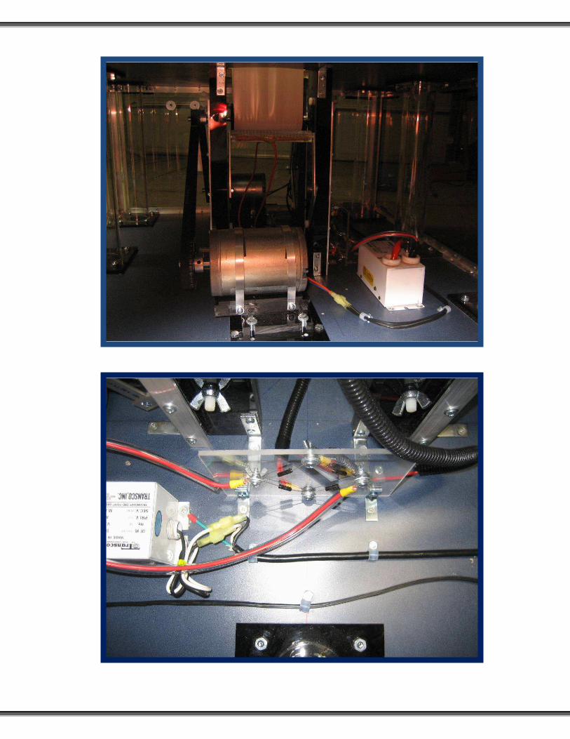
Spraying a Charge:
Some of the diehard VDG
enthusiast will take the extra steps as to install
a charged spray system that will in turn allow
the system to produce more current. This
charging process is done by placing a positive
charge on the bottom roller and negative
charge on the bottom comb to force feed the
electrons onto the belt. This may be carried
out using an 8000V Neon Sign Transformer
(NST) along with a rectifier to straighten out
the 60hz AC current to a pulsing DC current.
On this page is a schematic diagram for the
spray charge system.
From my years of experience, I
would only recommend a spray charge system
if you do not have a sufficiently operating set
of rollers, otherwise, you will be able to
produce more charge in a field induced by
friction than an artificially induced
environment. I have found that with a nylon
Teflon roller combo, I can produce at least
twice as much charge than a sprayed system.
On the other hand, if it is a humid day, the
VDG roller will not be able to naturally
produce the charge therefore a sprayed system
is crucial. A sprayed system may also be
advantageous because the current sprayed to
the belt may be controlled using a variac
giving that operates a full range from zero to
the maximum operating current. The current
may also be controlled by adjusting the speed
of the drive system as in a traditional static
charged system.

27 Frederick W. Graff©2008 | Graff Generators
There are a variety of ways to design a
sprayed system depending upon how much
charge you would like to produce. The
current output is dependent upon how the
rollers are set up. Below is a list of roller
combinations for a sprayed system ranked
according to current output:
Top Roller Bottom
Roller
Output
Performance
(☺)
Teflon Nylon Wool
Coated in
Magnetic
Wire
☺☺☺☺☺
Teflon Aluminum ☺☺☺
Aluminum Aluminum ☺
The most current roller configuration
that I have used for my 1MV model was the
hybrid nylon wool coated (wrapped in
magnetic wire). This technique is appealing
because it creates the best of both worlds
because it invokes both the static properties of
the materials and the induced charge. Of the
two, the static charge takes the upper hand.
In the photos, though it is not
apparent, the wires are epoxied at various
locations and soldered to the axle. The
positively charged source was directed to the
bottom roller support system that was coated
in aluminum foil so that contact could be
made. When pursuing this technique, I
would first run the rollers with the belt
connected, minus the magnetic wire, in order
to press down the wool.
29 Frederick W. Graff©2008 | Graff Generators
Perhaps the most alternative route of producing a VDG is to make a pelletron which is a device
that does not depend upon a static charging system but mini capacitors that are charged at the base
and then transport the charge to the dome. This form of charging in the presence of sulfur
hexafluoride is used for generators that produce 5 MV and more. Such equipment is obviously not
meant for the amateur science hobbyist, however that does not mean that you cannot dabble just a
little. Below are a few links pertaining to how the pelletron functions and simple homemade
pelletrons. Hope you enjoy!
Pelletron Resources
http://www.geocities.com/marktecson/pelletron.htm (Build your own)
http://www.youtube.com/watch?v=fNz5trXBZIg (Video of Homemade Pelletron)
http://www.pelletron.com/(Operation and Manufature)
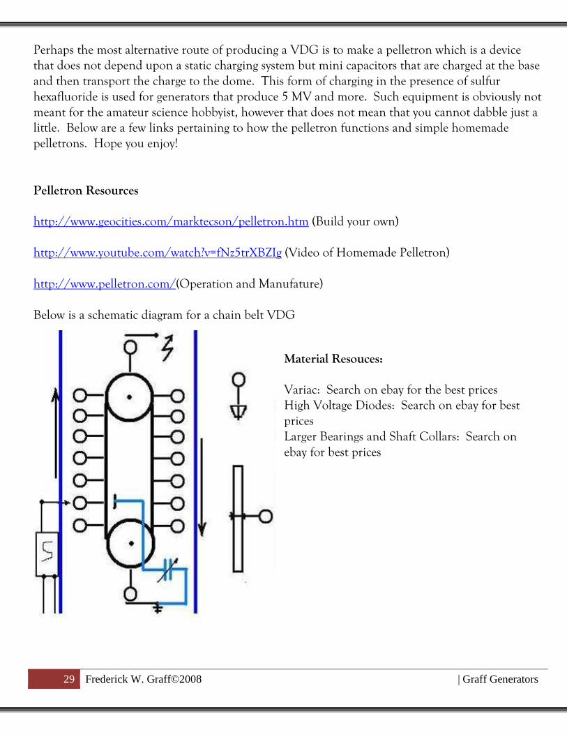
Below is a schematic diagram for a chain belt VDG
Material Resouces:
Variac: Search on ebay for the best prices
High Voltage Diodes: Search on ebay for best
prices
Larger Bearings and Shaft Collars: Search on
ebay for best prices

30 Frederick W. Graff©2008 | Graff Generators
Extra Resources:
~ Van De Graaf Generator Videos~ http://www.youtube.com/watch?v=vMpNXIZK5u8&feature=related ……………(Very Rustic Design)
http://www.youtube.com/watch?v=OyS5bZx1fns&feature=related ………………(Rustic Design)
http://www.youtube.com/watch?v=ecXmq71A5Xc&feature=related …………….(Miniture VDG)
http://www.youtube.com/watch?v=4szKjLsa5lY&feature=related …………………(Very Nice Design)
http://www.youtube.com/watch?v=lgCo8WqOQS8&feature=related …………..(Very Rustic Design)
http://www.youtube.com/watch?v=7qgM1A3pgkQ&feature=related ……………(Mythbuster’s
Generator)
http://www.youtube.com/watch?v=U2NmIVSX9OM&feature=related …………(Very Nice Design)
http://www.youtube.com/watch?v=I2G0IdTWGQU ……………………………………(How a VDG
Works)
http://www.youtube.com/watch?v=1qX6eUXpW5c&feature=related ……(Very Nice Design)
~Van de Graaf Generator Documents and Websites~ http://www.instructables.com/id/Be-a-Scientist%3a-Build-an-Electrostatic-Motor . Build
electrostatic Motors
http://www.sciencefirst.com/artcls/9.pdf#search='build%20graaf%20generator' ..(Building a Toy
VDG)
http://freespace.virgin.net/paul.z/VDG/vp1.htm#Van%20De%20Graaff.... (Beautiful Design)
http://www.physics.ucla.edu/demoweb/demomanual/electricity_and_magnetism/electrostatics/va
n_der_graaff_experiments.html .....(Experiments)
http://web001.greece.k12.ny.us/files/883/Van%20de%20Graff%20generator%20demonstrations
.pdf …….(Demonstrations)
http://www.metacafe.com/watch/2478358/van_de_graaff_demonstrations ...(Demonstrations)
http://www.waynesthisandthat.com/vandegraaff.htm ...(Types of VDGs and Arcs)
http://www.goldmine-elec-products.com/prodinfo.asp?number=C6917 …(The 90 dollar kit)
http://www.scribd.com/doc/2602893/Midget-Van-De-Graaff-Generator ....(Midget VDG)
31 Frederick W. Graff©2008 | Graff Generators
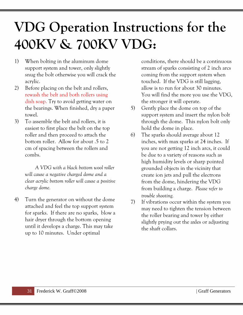
VDG Operation Instructions for the
400KV & 700KV VDG: 1) When bolting in the aluminum dome
support system and tower, only slightly
snug the bolt otherwise you will crack the
acrylic.
2) Before placing on the belt and rollers,
rewash the belt and both rollers using
dish soap. Try to avoid getting water on
the bearings. When finished, dry a paper
towel.
3) To assemble the belt and rollers, it is
easiest to first place the belt on the top
roller and then proceed to attach the
bottom roller. Allow for about .5 to 2
cm of spacing between the rollers and
combs.
A VDG with a black bottom wool roller
will cause a negative charged dome and a
clear acrylic bottom roller will cause a positive
charge dome.
4) Turn the generator on without the dome
attached and feel the top support system
for sparks. If there are no sparks, blow a
hair dryer through the bottom opening
until it develops a charge. This may take
up to 10 minutes. Under optimal
conditions, there should be a continuous
stream of sparks consisting of 2 inch arcs
coming from the support system when
touched. If the VDG is still lagging,
allow is to run for about 30 minutes.
You will find the more you use the VDG,
the stronger it will operate.
5) Gently place the dome on top of the
support system and insert the nylon bolt
through the dome. This nylon bolt only
hold the dome in place.
6) The sparks should average about 12
inches, with max sparks at 24 inches. If
you are not getting 12 inch arcs, it could
be due to a variety of reasons such as
high humidity levels or sharp pointed
grounded objects in the vicinity that
create ion jets and pull the electrons
from the dome, hindering the VDG
from building a charge. Please refer to
trouble shooting. 7) If vibrations occur within the system you
may need to tighten the tension between
the roller bearing and tower by either
slightly prying out the axles or adjusting
the shaft collars.

32 Frederick W. Graff©2008 | Graff Generators
Trouble Shooting: 1) Problem: Humid day. This will
decrease the voltage by half. That is why
they say we have good VDG weather
and bad VDG weather.
Solution: Blow a hair dryer through
the bottom of the VDG roller entrance
hole.
2) Problem: Dust particles on dome that
cause leakage.
Solution: Clean the dome after each
hour of use. Even small dust particles
will cause points of leakage. To see the
points of leakage, run the VDG with the
lights out and look for small blue ion
jets. Brush the ion jet away and the
VDG will produce rather large arcs. Be
very careful while trying this technique.
3) Problem: High mineral content in
water used to wash the belt. This will
completely shut the VDG off.
Solution: Try washing the system with
distilled water which may be purchased
at the grocery store.
4) Problem: Oil on belt and rollers. This
will shut the VDG off.
Solution: Wash the top and bottom
roller with soapy water.
5) Problem: Belt is not dry enough after
washing. This will shut the VDG off.
Solution: Blow hot air up through the
bottom of the tower while running.
6) Problem: Dusty belt. This will deter the
charge a little.
Solution: Clean the belt with soapy
water.
7) Problem: Pointed metal objects around
the VDG will cause it leak.
Solution: The VDG cannot be around
pointed objects because they will
prematurely pull charge from the dome
and not allow it to build to its
maximum potential. Keep the VDG
located in open space.
8) Problem: Belt begins to rub on the
combs at very high speeds.
Solution: Once the belt develops a large
amount of ware, it will loosen and
possibly brush the combs during
operation. This will indicate that it is
time to change the belt. These belts are
made from a latex material and will
break down in UV light, therefore when
finished using the VDG, take off the
belt and place it in a dark location.
These belts should last a very long time
if stored correctly.
VDG Maintenance: 1) Do not allow the belt to come in contact
with the combs during operation in order
to maximize the belts life
2) Latex will oxidize when in the presence of ozone or UV light. The ozone is inevitable
due to the voltage produced however the
UV will inflict a significant amount of
damage over time, therefore always store
the belt in a dark place when not in use.
3) Never clean with alcohol or acetone due to sever cracking of the acrylic.
4) The VDG belt and rollers may be cleaned with dish soap and water. Try to avoid
water contact with the bearings.
5) All parts of the VDG charging system (dome, belt and rollers, and tower should
be cleaned every 2hours of run time.
VDG Safety: 1) VDG’s should not be used around people
with heart condition or pacemakers.
2) Be careful not to make items that will act as high voltage capacitors. The current
from the VDG’s are fairly safe, however
when the current is allowed to store at
such high voltages they can become lethal.
3) Larger VDGs over 300KV will produce welts from prolong exposure to arcs.
4) Keep away from all electronics and outlets that are connected to them.
5) Operate in well ventilated areas due to the ozone produced.
6) Avoid making human chains.
Experimenter Ideas: 1) Insulate yourself and touch the VDG while
pointing at various objects in the room to
place a charge on. When done to a
chandelier it will cause arcs within the chain.
2) Insulate and charge yourself with
700,000V and then step off of the insulated
material and experience the feeling of your
body just electrically shut off from the field.
3) Wrap the bottom roller with a metallic
coating and force feed it with a
15,000V charge to induce higher currents.
These VDG are designed to do so. (Very
Dangerous)
4) Wrap a balloon in foil and then hang it
from a string attached to the ceiling so that it
can touch the dome. Turn on the VDG and
watch the outcome.
5) Take two pie pans and attach a positive
and negative lead from the VDG to each pan.
Next place small foil leaves between the pans
or string. Very cool to see!
6) Bring fluorescent tubes near the VDG.
This makes a great visual for examining
electric fields. The tube will begin to glow at
5 feet away.

34 Frederick W. Graff©2008 | Graff Generators
7) Charging Lynden Jar and high voltage beer
cup capacitors (Dangerous!!!)
8) Place pie pans on the generator and watch
them fly.
9) Static electricity motors and ion jets.
10) Just insulate yourself to feel your entire
body light up from being immersed in the
700,000V electric field. ABSOLUTELY
AWESOME!!! However, if someone touches
you....ouch! This seems to be my students
favorite thing to do especially with the x-large
770KV VDG where they will develop 8 inch
arcs coming off of them when approached.
Yes, this is a crowd pleaser!!!
All of these demos are extremely fun and exciting to do, however as in every situation when
experimenting, please consider all dimensions of safety. Use at your own risk.