Embed Size (px)
Citation preview
OSGAR: A Scene Graph with Uncertain Transformations
Enylton Machado CoelhoBlair MacIntyre
GVU Center, College of ComputingGeorgia Institute of Technology
Atlanta GA{machado, blair}@cc.gatech.edu
Simon J. Julier
Virtual Reality LaboratoryAdvanced Information Technology
Naval Research LaboratoryWashington DC
Abstract
An important problem for augmented reality isregistration error. No system can be perfectly tracked,calibrated or modeled. As a result, the overlaid graphicswill not align perfectly with objects in the physical world.This can be distracting, annoying or confusing. In thispaper we propose a method for mitigating the effects ofregistration errors that enables application developersto build dynamically adaptive AR displays. Our solutionis implemented in a programming toolkit called OSGAR.Built upon OpenSceneGraph (OSG), OSGAR statisticallycharacterizes registration errors, monitors those errorsand, when a set of criteria are met, dynamically adaptsthe display to mitigate the effects of the errors. Becausethe architecture is based on a scene graph, it provides asimple, familiar and intuitive environment for applicationdevelopers. We describe the components of OSGAR, discusshow several proposed methods for error registration canbe implemented, and illustrate its use through a set ofexamples.
1. Introduction
Registration errors can have a profound impact on theeffectiveness of an augmented reality (AR) system. Thepurpose of many AR systems is to provide informationto the user about objects by aligning graphics with thoseobjects in the physical world. However, no AR systemis perfect. Tracking systems cannot measure the pose oftheir sensors exactly. Internal system calibration parameterscannot be known perfectly and the world cannot be modeledprecisely. As a result, the graphics will not align perfectlywith the objects in the physical world. In some situationsthese errors can be little more than an annoyance. However,in other situations the annotations could be ambiguously
placed (it is not clear what object they refer to) or appearto be placed on the wrong object altogether.
The conventional approach to registration errors isto consider them as a type of tracking problem. Apartfrom a few notable exceptions, none of them recent(e.g., [1], [13]), they are rarely addressed directly. Theprevailing assumption seems to be that, given bettertracking and faster computers, the major causes ofregistration errors will be overcome. However, we do notbelieve that this is the case, especially when one considersmobile augmented reality systems where one cannot relyon accurate, fixed infrastructure in carefully controlledsettings.
We believe that a better approach is to assume thatregistration errors will be inevitable, and provide applica-tion developers with tools to help them understand anddeal with these errors. In particular, we believe that anyAR toolkit should also help developers choose and displayannotations in such a way that the effects of registrationerrors are minimized.
Our first attempt at developing an adaptive user interfacewas to introduce the concept of a Level of Error 3D scenegraph node [10]. Analogous to Level of Detail (LOD) nodes(that switch between different representations of an objectbased on the projected size of the object), an LOE nodeis a switch node that uses an estimate of the registrationerror of an object to select the appropriate annotation stylefor a particular object in a scene. In [11] we described animplementation of the LOE which considered the problemof estimating and adapting to the registration error of asingle object. The only sources of error were due to thetracker and calibration errors.
However, despite its appeal to conventional graphicsscene graphs, the LOE is not sufficient to handle all of thepossible strategies that are needed to adapt to registrationerror. For example, the LOE considers each object individ-ually. Furthermore, the LOE only allows a finite set of fixed
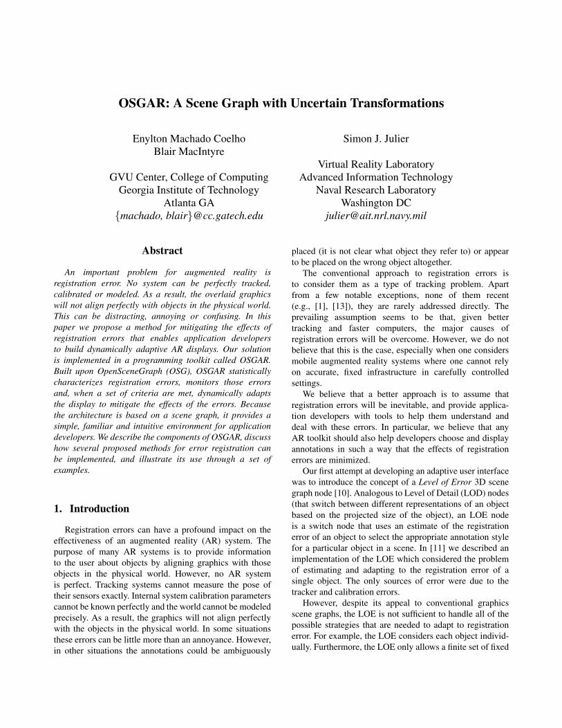
(a) (b) (c)
Figure 1. In (a) two drawers are labeled, but the target of the labels is ambiguous. In (b) all drawers arelabeled, reducing ambiguity but cluttering the space. In (c) the two drawers are labeled with calloutlines that point to unambiguous locations on the appropriate drawer.
displays, limiting it to handling a small number of cases.In this paper, we present the design and implementation
of a programming toolkit for AR, called OSGAR, thatprovides a general framework for propagating errorestimates from an arbitrary collection of sources, andcreating adaptive interfaces based on these estimates. Itconsists of three main components: an error propagationmechanism (which calculates the uncertainty at any pointin the scene graph), a set of components for adaptation(such as replacing models of objects with callout labels andlines), and a set of common facilities required for manytypes of AR applications (including support for trackers,video-in-the-background and fiducial tracking).
The structure of this paper is as follows. Section 2provides several motivating examples. Section 3 describesthe sources of registration error we are concerned with.Section 4 describes the uncertainty representation and themathematical framework used to compute the estimate ofthe registration error. The architecture and implementationof OSGAR is described in Section 5. This section alsodescribes some of the techniques which can be used toimprove the quality of the augmentation presented to theuser as well as the quality of interaction. The limitationsand future directions of OSGAR are discussed in Section 6and conclusions are drawn in Section 7.
2. Motivating examples
While some AR domains require precise registration(e.g., AR-guided surgery [13]), there are many domainswhere AR could be usefully applied that do not requireprecise registration. For example, consider a system thattries to label two empty drawers in the tool cabinet in
Figure 1(a). While the labels are small enough to fit withinthe projected area of the drawers, a small amount ofregistration error makes it unclear which drawer the labelsare referring to. Furthermore, because all drawers lookthe same there are no obvious visual clues a user couldemploy to resolve the ambiguity. One solution, shown inFigure 1(b), is to label all the drawers, so the user caninfer the registration error offset. However, even for thisrelatively small amount of registration error, adding allthirty labels unnecessarily clutters the user’s view of theworld. A better solution in this case, shown in Figure 1(c),would be to offset each label so it does not cover any partof the target drawer, and use a callout line to point to alocation on the display that is likely to overlap some part ofthe drawer.
Another example is the recent evaluation (by Hondaand Microvision1) of a wearable maintenance systemthat uses a non-tracked see-through heads-up displayto present in-situ automotive maintenance informationsto trained technicians. This system was demonstrablyuseful (resulting in a quoted 38% improvement over thenon-wearable version) despite the fact that the graphicswere not registered with the physical world. This systemraises some interesting questions for the AR community:would an AR version of the system be even more effective?Would precise registration be necessary, or would a coarselyregistered version using moderately accurate tracking be aseffective (e.g., by allowing the current system’s graphicsto be generated from technician’s approximate viewpoint,even if they aren’t registered)? Would some tasks benefit
1 For more information, see http://www.microvision.com/nomadexpert/field.html

greatly from precise registration, while others would not?When one considers practical issues of creating, deployingand maintaining such a system, such as cost and robustness,these questions become critical.
To continue with the above example, perhaps somerepair shops would have good tracking, and others wouldnot. Perhaps tracking quality would vary with the modelof the car (e.g., new cars might have “embedded trackers”,old ones would not), or the location in the shop or parkinglot. Perhaps trackers break occasionally. For whateverreason, a commercially viable repair system such as thiswould need to function in a variety of situations, andideally adapt automatically as the situation changes (e.g.,as the technician walks around the shop). As an applicationdesigner, it is easy to imagine many different displaymodes for such a system, based on different amountsof registration error. What is hard is actually computingreasonable estimates of registration error for the differentgraphical objects in the system, and creating a graphicaldisplay system that uses these estimates to select theappropriate display modes. OSGAR is designed to addressthis problem.
3. Sources of uncertainty
For OSGAR, we consider the following classes ofuncertainty [8]: tracking, calibration, and modeling.
Tracking. Tracking systems estimate, in real-time, thepose of a tracked object. There are literally hundreds ofpapers which describe different tracking methods based ona variety of sensing technologies (e.g., magnetic, ultrasonic,inertial, computer vision, etc.), as well as hybrid systemsthat combine more than one of these technologies. However,as noted by Welch and Foxlin, there is no “Silver Bullet”that is likely to provide perfect tracking [16]. Therefore, anytracking system should be assumed to return error-corruptedestimates of the true pose of the sensor. These errors can bemodeled statistically. However, it is often very difficult toprovide precise, high-order statistical descriptions of theseerrors, especially since many tracking systems are closedblack-boxes, making it impossible to know what signalprocessing is carried on within them.
Therefore, we assume that the measurement from atracker can be considered to be the mean of the distributionand the uncertainty can be represented by the covariance.Some tracking systems (such as the Intersense VisTrackerand GPS receivers that support the NMEA GST message)provide covariance information directly. However, manytracking systems only provide performance specificationsand the covariances must be approximated from these.2
2 For example, if the specifications consist of a hard bound on the errors,the standard deviation can be set to be a third or a quarter of this value.
Calibration. An AR system consists of a trackingsystem and a display system and the calibration of thesesystems and the relationship between them must beknown. For example, in video-mixed AR systems theintrinsic parameters of the camera (such as its opticaldistortion) must be computed. Calibration parameterscan be accurately computed off-line for a camera witha specific focus and zoom setting by looking at a staticscene with a set of calibration patterns in it. However,there is no guarantee that these parameters are correct for amoving camera in a scene with different camera settings.The problems are exacerbated in see-through AR systemsbecause current methods require the user to align objectson the display with those in the physical world (e.g.,SPAAM [14] or the alignment framework described in [2]).Issues such as fatigue, the finite sampling space and usererror can lead to inaccuracies. The errors can be calculatedusing perturbation methods.
Modeling. Models are approximations of the physicalobjects they are meant to represent. Models can be acquiredin many ways, from a tape measure to 3D scanning laserrange finders. However, measurements always containerrors. The environment can change in unmodeled ways.The GIS community has been cognizant of the effects oferrors for a great deal of time [15] and the GeographyMarkup Language (GML) includes a schema for dataquality which is expressed using means and covariances.Therefore we assume that the raw model constitutes a meanestimate and each vertex in the model contains errors.
Several issues should be noted. First, each of these errorsources include temporal elements that OSGAR does notcurrently address. Latency throughout all components of thesystem, time synchronization across multiple devices, andthe discrete update times of displays and the rendering sub-systems create errors which can be considered to increasethe error in the tracker [8]. Second, some of these errors areview dependent and some are view independent. The errorin the model is not, for example, a function of the positionand orientation of the user’s head. However, the projectionof the model onto the user’s display is a function of theusers view. As described below, this distinction is usedto optimize the error propagation mechanism. Finally, weare not aware of any widely-used modeling format whichincludes information about the imprecision of the model,so we do not currently support models with errors on eachvertex. However, it would be straightforward to modify thesystem to support such models if they existed.
4. Error representation and propagation
Uncertainty in OSGAR is represented by adding acovariance matrix to the transformation nodes in thescene graph. Any transformation matrix is considered to

be the mean of a probability distribution function (PDF)for that transformation, instead of just a single discretetransformation. If no uncertainty information is specifiedfor a transformation, it is assumed to be exact. The meanof the PDF (i.e., the original transformation) is used forculling, rendering, and so on, as before.
No restrictions are placed on the form of thetransformation matrices; the scene graph is assumedto be composed of arbitrary nodes with arbitrary affinetransformations between them. Specifically, let M j
i be thetrue relative transformation from node i to node j ,
M ji =
⎡⎢⎢⎣
m11 m12 m13 m14
m21 m22 m23 m24
m31 m32 m33 m34
m41 m42 m43 m44
⎤⎥⎥⎦
Each element can take arbitrary values.3 To parame-terize such a general matrix, a number of authors havedeveloped methods to decompose an arbitrary matrix intoa set of primitive operations including rotation, transla-tion and scale [12, 6]. However, these decompositions areconstructed by applying potentially expensive nonlinearoperations (such as single value decomposition). Becausethe graph can be extremely large, a significant number ofthese decomposition operations might be performed leadingto significant computational costs. Therefore, to simplifythe implementation, all errors are expressed directly interms of the elements of the transformation matrix. In otherwords, the uncertainty is a 16-dimensional state whichcorresponds to each element in the transformation matrix.This is a straightforward generalization of the approach ofBar-Itzhack for direction cosine matrices [3].
Mnr is the cumulative transformation matrix from the root
node R to an arbitrary node N. This transformation is givenby:
Mnr = ∏
∀i∈P
Mii−1, (1)
where p is the path from the root node R to an arbitrarynode N and i are nodes in this path.
However, the system does not have access to these truevalues. Rather, it only has access to the estimated relativetransformation M̂ j
i . The difference between the two is due tothe sources of uncertainty outlined in Section 3. As a result,the cumulative transformation calculated in the graph is:
M̂nr = ∏
∀i∈P
M̂ii−1 (2)
Therefore, the problem is to estimate the statistics of M̂nr
given that error can be introduced at any transformation inthe tree.
3 It is not even possible to assume that m44 = 1.
The error introduced at a node is assumed to be anadditive matrix,
M̂ ji = M j
i +δM ji . (3)
Therefore, the error propagation equation is
Mir +δMi
r =(Mi
i−1 +δMii−1
)(Mi−1
r +δMi−1r
)= Mi
i−1Mi−1r +Mi
i−1δMi−1r (4)
+δMii−1Mi−1
r +δMii−1δMi−1
r
Assuming that the error introduced at a node isindependent of the error introduced at preceding nodes, theexpected value of the last term will always evaluate to 0and thus can be neglected. Therefore, the equation whichpropagates the error down the scene graph is as follows:
M̂ir = M̂i
i−1M̂i−1r
δMir = Mi
i−1δMi−1r +δMi
i−1Mi−1r
(5)
However, this representation has two main difficulties:
• It is more computationally expensive. If one assumed,for example, that the matrix only encoded translationrotation and scale then only 9 or 10 parameters wouldbe required. However, this is at the cost of introducingcomplicated nonlinear transformations at each node torecover the parameters (and their uncertainties) after atransformation is applied.
• The representation does not capture the nonlinearconstraints which exist between matrix elements.For example, large orientation errors are not simplyadditive. These could be partially overcome by usingmore sophisticated models. For example, the errorcould be treated as being multiplicative and of theform I + δMi
i−1 where I is the identity matrix. Arecursive relationship exists in this case.4 However,any representation is always an approximationand, for this paper, we chose the simplest usableapproximation.
Despite these limitations, we believe this representationis appropriate for the needs of OSGAR:
• The transformation operations on each node aresimple. The transformation consists of a single matrixmultiplication which only involves basic arithmeticoperations.
• The complexity of specifying nonlinearities (e.g.,tracker errors) are only introduced at the nodes wherethe errors occur.
4 The mean term is the same but the error propagation term becomes
δMir = δMi−1
r +(Mi−1
r
)−1 δMii−1Mi−1
r .
OSG Runtime Graph TraversalThree Basic Visitors: Application Callback, Cull, Render
OSG Programming Classes
OSGAR Runtime Graph Traversal(Three New Visitors between OSG Application and Cull)
OS
GA
R P
rog
ram
min
g C
lass
es
Tracked
Transform
Space
ManagerHUD
OSGAR
Video
Viewer
VRPN
Interface
ARToolkit
Interface
Camera
Interface
Error
Region
Error
Assessment
Transform
Combiner
Error
Bounder
Label
PlacerLOE
OSGAR
Transform
Vision
Transform
VRPN
Transform
OSGAR
Group
OSG
Transform
OSG
Group
OSG
Viewer
CommunicationInheritance
Optimization
Visitor
Registration Error and
Augmentation Visitor
Uncertainty
Propagation Visitor
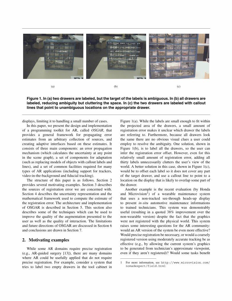
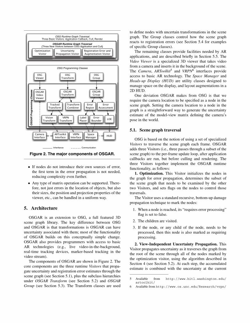
Figure 2. The major components of OSGAR.
• If nodes do not introduce their own sources of error,the first term in the error propagation is not needed,reducing complexity even further.
• Any type of matrix operation can be supported. There-fore, not just errors in the location of objects, but alsotheir sizes, the position and projection properties of theviewer, etc., can be handled in a uniform way.
5. Architecture
OSGAR is an extension to OSG, a full featured 3Dscene graph library. The key difference between OSGand OSGAR is that transformations is OSGAR can haveuncertainty associated with them; most of the functionalityof OSGAR builds on this conceptually simple change.OSGAR also provides programmers with access to basicAR technologies (e.g., live video-in-the-background,real-time tracking devices, marker-based tracking in thevideo stream).
The components of OSGAR are shown in Figure 2. Thecore components are the three runtime Visitors that propa-gate uncertainty and registration error estimates through thescene graph (see Section 5.1), plus the subclass hierarchiesunder OSGAR Transform (see Section 5.2) and OSGARGroup (see Section 5.3). The Transform classes are used
to define nodes with uncertain transformations in the scenegraph. The Group classes control how the scene graphreacts to registration errors (see Section 5.4 for examplesof specific Group classes).
The remaining classes provide facilities needed by ARapplications, and are described briefly in Section 5.5. TheVideo Viewer is a specialized 3D viewer that takes videofrom a camera and inserts it in the background of the scene.The Camera, ARToolkit5 and VRPN6 interfaces provideaccess to basic AR technology. The Space Manager andHeads-up Display (HUD) are utility classes designed tomanage space on the display, and layout augmentations in a2D HUD.
One deviation OSGAR makes from OSG is that werequire the camera location to be specified as a node in thescene graph. Setting the camera location to a node in thegraph is a straightforward way to generate the uncertaintyestimate of the model-view matrix defining the camera’spose in the world.
5.1. Scene graph traversal
OSG is based on the notion of using a set of specializedVisitors to traverse the scene graph each frame. OSGARadds three Visitors (i.e., three passes through a subset of thescene graph) to the per-frame update loop, after applicationcallbacks are run, but before culling and rendering. Thethree Visitors together implement the OSGAR runtimefunctionality, as follows:
1. Optimization. This Visitor initializes the nodes inthe graph for error propagation, determines the subset ofthe scene graph that needs to be examined by the othertwo Visitors, and sets flags on the nodes to control thosetraversals.
The Visitor uses a standard recursive, bottom-up damagepropagation technique to mark the nodes:
1. When a node is reached, its “requires error processing”flag is set to false.
2. The children are visited.
3. If the node, or any child of the node, needs to beprocessed, then this node is also marked as requiringprocessing.
2. View-Independent Uncertainty Propagation. ThisVisitor propagates uncertainty as it traverses the graph fromthe root of the scene through all of the nodes marked bythe optimization visitor, using the algorithm described inSection 4 (see Section 5.2). At each step, the accumulatedestimate is combined with the uncertainty at the current
5 Available from http://www.hitl.washington.edu/artoolkit/
6 Available from http://www.cs.unc.edu/Research/vrpn/
node using Equation 5, giving an estimate of the uncertaintyof that node expressed in the local coordinates of that node.This computation is done for both OSG and OSGARtransformation objects, with the OSG transformationsassumed to be precisely specified with no error.
Each time one of the OSGAR Group nodes is visited, theaccumulated uncertainty is stored at that node, for use inthe next traversal. (Note that since OSG supports directedacyclic graphs, a single node could lie on multiple pathsfrom the root. The propagated uncertainty is stored foreach path to the root of the graph, and tagged with a pathidentifier so it can be recovered when needed.) Any Trans-formation Combiner nodes encountered during traversal arealso handled by this visitor (see Section 5.2.2).
3. Registration Error Visitor. Before starting thisVisitor, the uncertainty of the camera location (obtainedfrom the node representing the camera in the scene graph)is combined with the projection matrix (which may alsoinclude uncertainty). As the Visitor traverses the graph,the camera uncertainty is combined with the uncertaintyat each OSGAR Group node, creating a view-dependentestimate of uncertainty. This uncertainty estimate is usedto compute screen-space estimates of registration errorneeded by the OSGAR Group nodes (see Section 5.3).
For efficiency, this Visitor collects the vertices of allgeometry in the subtree under each Group node (wheneverany part of the subtree is damaged) and stores a 3D convexhull of those points in the Group itself. The points in the3D hull are used by the Group nodes when computing theview-dependent registration error estimates.
5.2. Transform nodes
The OSGAR Transform base class extends OSGTransform by using its existing 4×4 transformation matrixas the mean of the distribution of the transformation, andassociating uncertainty (in the form of a 16×16 covariancematrix) with this 4×4 transformation. A collection ofutility methods are provided for setting and retrieving theuncertainty information in various forms. The covariancematrix can take on the special values perfect (to indicate thatthere is no uncertainty associated with this transformation)and infinite (to indicate that the value of the transformationis unknown, and the link should not be followed). The lattervalue could be used, for example, when a tracker is notreporting (e.g., the user is out of range, or a fiducial markeris not currently seen).
A programmer can use OSGAR Transformdirectly, to create a node in the graph with somefixed uncertainty. For example, if the location of anobject in the environment was measured relativelycarefully, a position of +/- a few millimeters and anorientation of +/- a few degrees could be specified via
method calls to setPositionCovariance(dx, dy, dz) andsetOrientationCovariance(dh, dp, dr) (where dh, dp and dyare the covariances for heading, pitch and roll respectively).
Several subclasses of the Transform node exist.
5.2.1. Tracked transform nodes One common sourceof uncertain transformations is external tracking systems.OSGAR TrackedTransform is a subclass of OSGARTransform whose values are updated automaticallyfrom some tracking system. This class has methods(implemented by each subclass) to determine if thetracker is currently reporting or not. The value of thetransformations on each TrackedTransform is updatedby the tracker handler (see section 5.5). The currentimplementation of OSGAR supports two subclasses ofTrackedTransform:
• vrpnTransform creates a VRPN tracker client toconnect to a sensor of a local or remote VRPN trackerserver. The application developer specifies the trackername and network address, and the specific sensor toget transformations from.
• visionTransform implements a vision-based tracker,currently using the ARToolkit. The applicationdeveloper specifies the marker that this Transformationshould be attached to. The transformations receivedare the position of the fiducial relative to the camera,so the visionTransform is typically attached to thescene graph node representing the location of thecamera.
Currently, neither VRPN nor ARToolkit provideuncertainty estimates for their trackers, so we set theuncertainty manually on these nodes, typically based on themanufacturers specifications and our experience. We are inthe process of adding uncertainty support to VRPN, andenhancing specific VRPN servers to support it (e.g., manyGPS units provide an estimate of their current accuracy, andone major tracking company is providing us with an SDKto retrieve covariance information from their trackers).Similarly, we are creating an accuracy estimator for theARToolkit.
5.2.2. Transformation combiner nodes The Transform-Combiner class is designed for situations where multiplepose estimates are available for an object. The program-mer can set up a Combiner to automatically combine thepose estimates, can leverage application or tracker specificknowledge to improve the accuracy of the fusion, or cansimply choose between the poses.
If multiple poses are available for a node in a scenegraph, there will be a path from the root to the node foreach pose. Normally, if a node is linked to a scene graphvia more than one path, the scene graph semantics dictate

(a)
F
T V
B1
C
B2
L
(b) (c)
Figure 3. The TransformCombiner C chooses which path to cube B1 (the near cube) to use for eachframe, based on the error propagated from T (a receiver for a fixed tracker) and F (a fiducial marker,measured relative to the video camera V). In (a) the fiducial markers are visible, and has much lowerestimated error than the fixed tracker, so the branch through F is used. The second cube is attachedto C via an LOE L that only displays it when the error is small. In (b) the fiducial is not tracked, so thefixed tracker is used (and the second cube is hidden by the LOE).
that it is rendered once for each path, usually at a differentlocation in the 3D world.
The TransformCombiner has different semantics. Aprogrammer-supplied callback function determines whichsingle incoming path to use for the subtree under theCombiner. The function is given the pose estimates for allof the paths leading into the Combiner, and returns a newestimate along with an indication of which incoming pathto use for all subsequent passes. The effect is equivalentto the children of the Combiner being attached to thatpath from the root, and the other paths terminating at theCombiner.
The most obvious scenario is when an object is trackedby multiple sensors, and the Combiner should fuse theposes using an approach such as the PDF intersectionmethod proposed by Hoff [7]. However, there are othermore mundane scenarios in which the combiner turns out tobe a very powerful way of structuring an AR scene graph.
For example, consider a user and object that are trackedby some reasonably accurate tracker (such as an IntersenseIS600 or an RTK GPS system, both of which give 1-2cmpositional accuracy), and the object can also be trackedusing the camera on the user’s video-mixed AR display. Ifthe system wants to add augmentations to the object, sensorfusion is not particularly useful — the absolute accuracyof a system such as the ARToolkit is not particularly good,but the registration obtained when using it is quite good.
(While both the translation error along the direction ofprojection and the rotation error are large, the translationerror is small perpendicular to the direction of projection.)In this situation, using the vision tracker when it reports,and falling back to the less accurate tracker otherwise, isprobably the right thing to do, as illustrated in Figure 3.
Perhaps more interestingly, suppose an object is trackedintermittently (such as by a vision tracker), but the objectalways remains within a certain area, such as on a desk thatit is tethered to by a cable. In most AR prototype systems,when the object is not tracked, its last known position isused. OSGAR supports more systematic solutions to thisproblem.
One simple solution would be to use a static Transformto specify a second pose for the object, and use aTransformCombiner to merge it with the tracked pose. TheTransform would be given a mean in the middle of thedesk and a large uncertainty, to capture the full range of theobject’s possible location.7 The Combiner would choosethis static transformation when the object is not tracked,but use the tracked path when possible. In this case, theCombiner would propagate the fixed transformation witha large error estimate or the tracked transformation witha very small error estimate. If the programmer simply
7 More complex solutions could also be implemented that take intoaccount the time since the object was last tracked, or leverage otherapplication-specific semantics.
uses the provided transformation (i.e., the mean of thedistribution) to render the augmentation, the resultingdisplay would be nonsensical (the object would jumpbetween the tracked location and the arbitrary “middle ofthe desk” location specified by the fixed transformation).
However, if the programmer makes use of the errorestimation nodes discussed below, the augmentation itselfcan change automatically when the magnitude of the errorchanges, and do so in a way that adapts to other aspects ofthe viewing situation. If the fixed area is, say, the top of adesk and the user is very close to the desk, the registrationerror (the projection on the 2D display) will be huge,requiring alternative display methods (such as using a 2Dinset window containing descriptive text). However, if theuser is far from the desk (say, on the other side of a largelab), the magnitude of the registration error on the 2Ddisplay may be quite small, allowing a 3D augmentationto be used. By specifying a range of augmentations touse, based on registration error on the 2D display, thesystem can adapt automatically to these very differentsituations. This example illustrates the power of OSGAR,and the approach programmers should take when buildingapplications using it.
Implementation. The Optimization Visitor countsthe number of paths that enter any Combiner node, andsaves the counter in the Combiner. Then, during theview-independent uncertainty propagation traversal,8 theCombiner collects the error estimates for every path intoit. When this visitor enters the Combiner via the finalpath, it activates the user specified callback function todetermine the final pose estimate and the path to use for thesubtree during the remaining traversals. Subsequent phases(registration error computation, culling, rendering) onlytraverse the subtree “under” the Combiner when they arrivealong this single path.
We are designing a range of sample callback functionsfor common Combiner functions. Currently, we haveimplemented a SmallestCovarianceCombiner that alwayschooses the smallest covariance, and uses it and its path asthe values for the subtree.
5.3. Basic group nodes
The OSGAR Group class is abstract, and providesaccessor methods to retrieve the view-independentuncertainty estimates that are computed by the propagationVisitor. The Assessment and Region subclasses provide
8 This decision should be made in the registration error visitor,using view dependent estimates, rather than in the view-independentuncertainty propagation visitor, using the view independent estimates.This will be changed in the near future when we re-implementthe visitors to solve a set of related problems, but the currentimplementation is sufficient for illustrating the desired functionality.
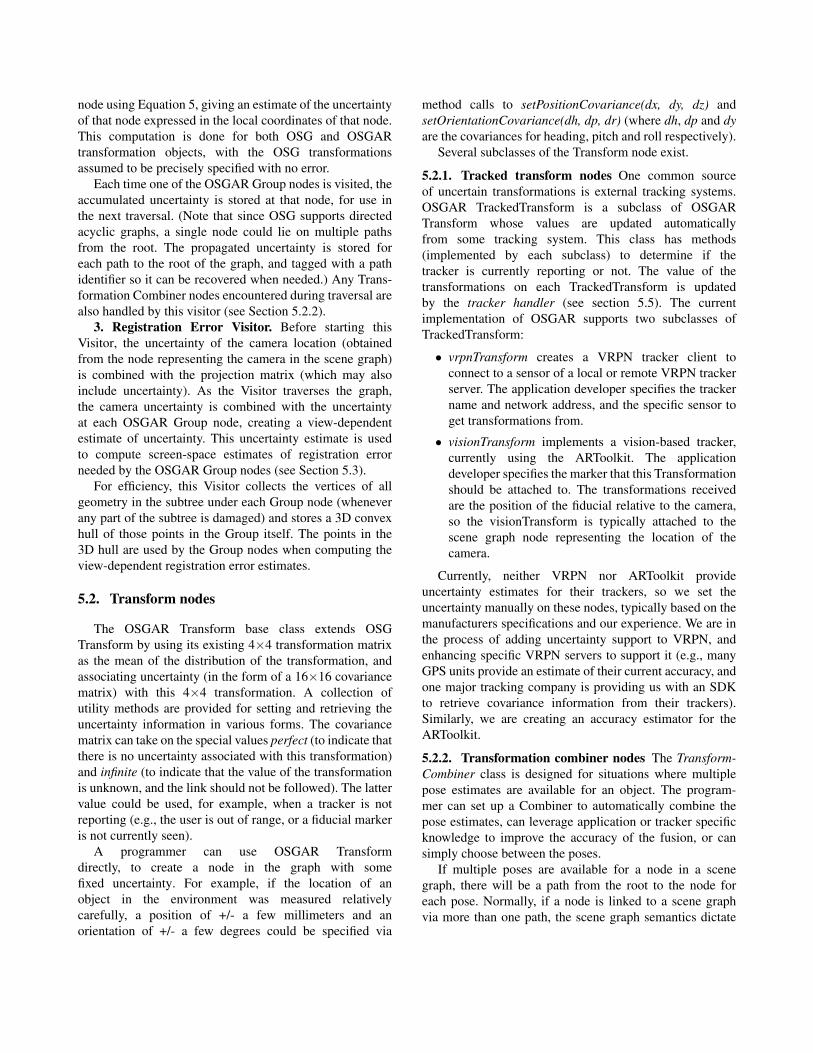
Figure 4. The registration error of cubesin the world. The blue ellipses representthe registration error around the vertices ofthe cubes. The green “outer” region is theconvex hull representing the area the entirebox will fall within, and the white “inner”region is the convex hull representing thearea that some part of the box should occupy.
access to two different representations of the registrationerror estimate of the objects in the tree under them.Recall from Section 5.1 that the registration error Visitorcomputes the 3D convex hull of the geometry in the subtreeunderneath all OSGAR Group nodes. The OSGAR Groupnodes use the view-dependent error estimate to computea 2D view-dependent convex hull of the points in this 3Dhull. The points in the 2D hull are used to compute theregistration error estimates.
Region classes. Regions provide the programmer witha collection of closed regions (illustrated in Figure 4):an error ellipse for each vertex in the 2D hull, an outerregion (the convex hull of all points in the error ellipses)representing the region that the object might intersect, andan inner region representing the region the object shouldintersect (see [11] for an explanation of how these regionsare computed).
Assessment classes. Assessments provide theprogrammer with a single floating point value representingan assessment of the magnitude of the registration error.The assessment is computed using two user-definedmethods: metric is run on each of the vertices in the 2Dhull, giving a floating point value for each. An aggregatoris run on the set of vertices and floating point values, andreturns the single value for the object. There are manypossible metrics that could be used by an Assessmentobject, such as the maximum of the main axis of theellipses, the area of the ellipse, etc. As an aggregatorfunction, one can consider the closest vertex, the average ofall vertices, etc.

5.4. Specialized group subclasses
We have implemented one subclass of Assessment(LOE) and two subclasses of Region (Bounding Regions,Label Placer) as examples of how to extend the basicGroup classes.
Bounding Regions. Used to display graphical represen-tations of the 2D convex hull: the vertex ellipses, the innerregion, the outer region, or any combination of them. It canbe used for prototyping, debugging or to create a simplehighlight of the region an object is expected to occupy.Figure 4 shows two cubes with all regions displayed.
Level of Error (LOE) Switches. The LOE (originallydiscussed in [10]) automatically chooses between differentsubgraphs within the scene graph, allowing the applicationdeveloper to specify different augmentations correspondingto the same physical object. At any time, one of the specifiedsubgraphs is enabled (visible) and the rest are disabled(invisible). The location of the LOE in the scene graphis used to determine the registration error estimate, butthe subgraphs do not need to be in the same part of thegraph. In our current implementation, the LOE choosesbetween its children and children attached to the HUD(discussed in Section 5.5), but it could easily be extendedto include subgraphs elsewhere in the scene graph. Duringeach traversal, one augmentation will be chosen based on tothe metric computed from the registration error estimate atthe LOE node.
Label Placer. The Label Placer computes where toposition the labels for a given object based on the computedinner and outer regions of the model. A programmer canchoose to keep the label overlapping the object (by keepingit inside the inner region) or guarantee that the label willnever block the object (by keeping it outside the outerregion). The Label Placer computes where to place thelabels each frame to enforce one of these constraints. TheLabel Placer uses a callback that specifies how to positionthe labels, for which we have implemented three simpleexamples. The first implementation positions the labelwhere there is the most space available, computed from thesides of the object to the limits of the screen. The secondimplementation always tries to position the label in thisorder: right, top, bottom and then left. If the label does notfit on the right side, then it tries to position it at the top, andso on. A third implementation favors edges closer to thescreen sides, to keep the middle clear. Labels that are notpositioned by the Label Placer are marked as not anchoredand passed to the Space Manager (described in section 5.5)to be handled there.
5.5. Additional AR components
As mentioned above, OSGAR provides a collection offacilities necessary for AR application development.
Video. Our current focus is on video-mixed AR exper-iences, so the OSGAR Video Viewer class allows a videostream to be texture mapped onto the background of thewindow. The Camera Interface also feeds video to theARToolkit for fiducial recognition.
Trackers. OSGAR supports both the tracking of fiducialmarkers and a wide variety of spatial trackers via theVRPN tracker package. Both are handled internally bya centralized tracker handler that performs the markerdetection on each new video image, polls VRPN once perframe, and updates the values of the associated TrackerTransformations in the scene graph when necessary.Trackers will eventually provide uncertainty estimates withtheir reports, although we have not finished extendingVRPN and the ARToolkit to do this.
HUD. The HUD class is used for displaying 2Daugmentations. It is implemented as an orthographicprojection attached to the camera position. Any kind ofOSG subgraphs can be attached to the HUD.
Space Manager. Currently a stand-in for a morepowerful space manager, such as that proposed by Bell andFeiner [4]. The class collects the regions created by theError Region classes into a set of Hull objects, and uses theHUD to display those that should be visible. Hull objectsstore all the vertex error ellipses, the inner and outer hulls,the path on the scene graph, and the object’s name. TheSpace Manager is also responsible for positioning labelsthat were not positioned explicitly by the Label Placers.
6. Discussion
Our method deals with the effects of dynamicallychanging static uncertainty on spatial registration error;OSGAR does not yet take into account temporal aspectsof such errors, nor does it try to take into account otherinfluencing factors, such as illumination.
We designed OSGAR to use several distinct Visitorsbecause we hope to eventually decouple the registrationerror computation from the display loop. Even though thesystem has proven to be sufficiently fast (we exceed 60frames per second on a dual 2GHz Pentium4 Xeon withan NVIDIA Quadro graphics card in our example and testprograms), we are concerned that a toolkit designed toreduce the impact of registration error should not increasethe latency of the system (and thus increase registrationerrors). Fortunately, the metrics we compute do notgenerally need to be synchronized with the display loop;if a Level-of-Error object or a Label Placement algorithmworks with data that is a few frames (i.e., a fraction of a
second) old, the result should be almost imperceptible tothe user. Even the computation of the 2D convex hulls doesnot need to be done synchronously, as long as the resultinggraphics are translated on the screen with the objects. If anobject is changing quickly, the computed regions may beslightly wrong, but most of the uses we propose for suchregions would not be adversely affected by such latency.
7. Conclusions
There has been increasing interest in the AR communityon how to engineer solutions that support the real deploy-ment of AR applications [9, 5]. We believe that the abilityto adapt to error estimates will form the foundation of ARsystems that are not tied to specific tracking and sensinghardware, and are thus more robust and deployable in awide variety of situations.
In this paper, we have introduced an architecture thatintegrates the uncertainty associated with the physicalworld into 3D computer graphics. We use this informationto automatically and efficiently estimate the registrationerror associated with each object in an AR system in realtime, and present a collection of sample programmingstructures that demonstrate how these estimates can be usedto improve the quality of the information being conveyedby the system.
We believe OSGAR represents an important step towardthe creation of real, robust AR systems in complex, mobileenvironments. By allowing programmers to deal withtracking technology (and other uncertainty) in a methodicaland structured way, they can focus on what the applicationshould do in different conditions, rather than tightlycoupling the system to a particular collection of devices.
8. Acknowledgments
The authors would like to thank Brendan Hannigan formany of the low-level AR libraries, Mike Ellison for theVidCapture wrappers for DirectShow (which are the basisfor our video library), researchers at UNC for VRPN, andthe many authors of the ARToolkit (which we use forfiducial marker tracking). This work was supported by theOffice of Naval Research under Contract N000140010361.
References
[1] R. Azuma and G. Bishop. Improving static and dynamicregistration in an optical see-through HMD. In ComputerGraphics (Proc. ACM SIGGRAPH ’94), Annual ConferenceSeries, pages 197–204, Aug. 1994.
[2] Y. Baillot, S. Julier, D. Brown, and M. Livingston. A trackeralignment framework for augmented reality. In Proceedings
of the International Symposium on Mixed and AugmentedReality (ISMAR ’03), pages 142–150, Tokyo, Japan, 7–10October 2003.
[3] I. Y. Bar-Itzhack and J. Reiner. Recursive attitudedetermination from vector observations: Dcm identification.Journal of Guidance, Control and Dynamics, 7(1):51–56,January – February 1984.
[4] B. Bell, S. Feiner, and T. Hollerer. View managementfor virtual and augmented reality. In ACM Symposium onUser Interface Software and Technology (UIST ’01), pages101–110, Nov 11–14 2001.
[5] E. M. Coelho and B. MacIntyre. High-level trackerabstractions for augmented reality system design. In TheInternational Workshop on Software Technology for ARSystems (STARS ’03), October 2003.
[6] R. Hartley and A. Zisserman. Multiple View Geometry.Cambridge University Press, 2nd edition, 2003.
[7] W. Hoff. Fusion of data from head-mounted and fixedsensors. In Proceedings of the First International Workshopon Augmented Reality (IWAR ’98), pages 167–182, 1998.
[8] R. L. Holloway. Registration Error Analysis for AugmentedReality. Presence: Teleoperators and Virtual Environments,6(4):413–432, August 1997.
[9] G. Klinker, T. Reicher, and B. Brugge. Distributed usertracking concepts for augmented reality applications. InInternational Symposium on Augmented Reality (ISAR ’00),pages 37–46, Oct 5–6 2000.
[10] B. MacIntyre and E. M. Coelho. Adapting to dynamicregistration errors using level of error (LOE) filtering. InInternational Symposium on Augmented Reality (ISAR ’00),pages 85–88, Oct 5–6 2000.
[11] B. MacIntyre, E. M. Coelho, and S. Julier. Estimating andadapting to registration errors in augmented reality systems.In IEEE Virtual Reality (VR ’02), pages 73–80, March 2002.
[12] K. Shoemake and T. Duff. Matrix animation and polardecomposition. In Proceedings of Graphics Interface (GI’92), pages 258–264, Vancouver, BC, Canada, May 11–151992.
[13] A. State, M. A. Livingston, G. Hirota, W. F. Garrett,M. C. Whitton, H. Fuchs, and E. D. Pisano. Technologiesfor augmented-reality systems: realizing ultrasound-guidedneedle biopsies. In Proceedings of SIGGRAPH 96, pages439–446, New Orleans, LA, August 4–9 1996.
[14] M. Tuceryan and N. Navab. Single point active alignmentmethod (SPAAM) for optical see-through HMD calibrationfor AR. In International Symposium on Augmented Reality(ISAR ’00), pages 149–158, Oct 5–6 2000.
[15] H. Veregrin. Error modeling for the map overlay operation.In M. Goodchild and S. Gopal, editors, Accuracy of SpatialDatabases. Taylor and Francis, London, UK, 1994.
[16] G. Welch and E. Foxlin. Motion tracking: No silver bullet,but a respectable arsenal. IEEE Computer Graphics andApplications, 22(6):24–38, 2002.