Embed Size (px)
Citation preview
HB 08-18-2010 1
Oscilloscope
Equipment SWS, BK Precision model 2120B oscilloscope,Wavetek FG3C function generator,2-3 foot coax cable with male BNC connectors, 2 voltage sensors
Reading How To Use Science Workshop, pp. 170-183 (scope display). Review the “Voltage,Current, and Resistance” writeup for the use of the SWS signal generator.
Remark The oscilloscope is a difficult instrument to understand, but it is also a very impor-tant instrument. Studying this write-up carefully before the lab will be worthwhile. Thislab cannot be approached casually.
1 Introduction
The standard instrument for examining time dependent voltages in a circuit is the oscillo-scope, or “scope” for short. Even if you are doing a DC experiment it is a good idea tolook at the circuit with a scope. You might find a large AC signal symmetric with respectto ground that does not show up on DC instruments but is affecting your experiment inundesirable ways, such as overloading a sensitive amplifier. Oscilloscopes are ubiquitous inthe medical profession. They are seen next to hospital beds showing the electrical output ofa heart. They are used extensively in operating rooms.
A voltage which depends on time can be drawn on graph paper with the voltage on thevertical axis and the time on the horizontal axis. If the voltage is periodic (repeats itselfafter one cycle) an oscilloscope will present a similar curve. By adjusting the scope it ispossible to display part of one cycle or many cycles of the waveform. Properties of a periodicvoltage, such as shape, peak-to-peak amplitude and period, can be measured. Is that sinewave from your signal generator distorted? Feed it into a scope and find out. Scopes haveother uses, but these are the primary subjects of this lab.
The oscilloscope is a sophisticated instrument. Competent use depends on understandinghow this instrument works. It is often necessary to consult the instruction manual for aparticular scope in order to use it effectively. The basic ideas are usually the same but areimplemented in different ways.
In this lab you will become familiar with 2 oscilloscopes, the model 2120B made by BKPrecision, and the SWS scope. Both these instruments do very much the same thing exceptthat the controls on the BK are mostly knobs and switches and those on the SWS are iconsand buttons. The SWS scope is digital. The input waveform is digitized and stored, at leastfor awhile. The BK scope is analogue. The input voltage may be amplified, but it is notdigitized and stored.
2 Analogue Oscilloscope Basics
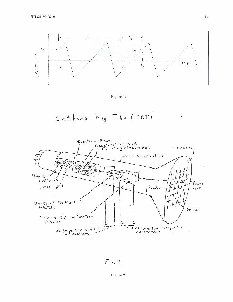
The heart of an analogue scope is a cathode ray tube (CRT). See Fig. 2. A cathode ray isan historical name for a beam of electrons. The “tube” refers to the glass vacuum envelope.Electrons are thermally emitted from a hot cathode. They are accelerated (through 2 kVin the BK scope) by an electrode and then focused into a thin beam by electrostatic lenses.A vacuum is necessary so that the electrons will not be scattered by air molecules and sothat the cathode will not burn up. The electron beam is then passed through 2 pairs of
HB 08-18-2010 2
deflection plates. A voltage across one pair of deflection plates deflects the electron beam inthe vertical direction, while a voltage across the other pair of deflection plates deflects theelectron beam in the horizontal direction. After passing through the deflection plates theelectron beam strikes a phosphor material that covers the inside surface of a flat portion ofthe vacuum tube. Light is emitted where the electron beam strikes the phosphor and someof this light passes to the outside of the tube and can be observed. If the electron beam issuddenly cut off, the light from the phosphor does not stop immediately but decays in lessthan a second. The flat part of the tube looked at is called the screen. When you are lookingat the screen the electron beam is coming toward you. By applying time dependent voltagesto the deflection plates the beam can be moved around the screen creating a pattern of lighton the phosphor often called a “trace.” As the light from the phosphor decays quickly thetrace must be continually refreshed by the electron beam so that the image on the screencan be observed. When the trace is “stationary” or “frozen” the electron beam continuallyrefreshes the trace by repetitively executing the same path on the screen. The screen hasa grid or graticule, usually in cm, which enables voltages (vertical deflections of the trace)and times (horizontal deflections of the trace) to be measured.
The image on a television screen that uses a CRT is formed the same way, except thedeflection of the beam is done magnetically rather than electrostatically. Many modern TV’sdo not use a CRT.
The most basic way in which a scope is operated is to apply the voltage you want toexamine (the input voltage) to the vertical deflection plates. The vertical deflection of theelectron beam and the trace will then be proportional to the input voltage. A linear rampvoltage, produced by the scope, is applied to the horizontal deflection plates. This rampvoltage sweeps the electron beam horizontally across the screen at a uniform rate. If theinput voltage is periodic, and the horizontal ramp voltage is also made periodic with anappropriate frequency, the scope trace will be a graph of the time dependent input voltage,with the vertical axis the input voltage and the horizontal axis the time.
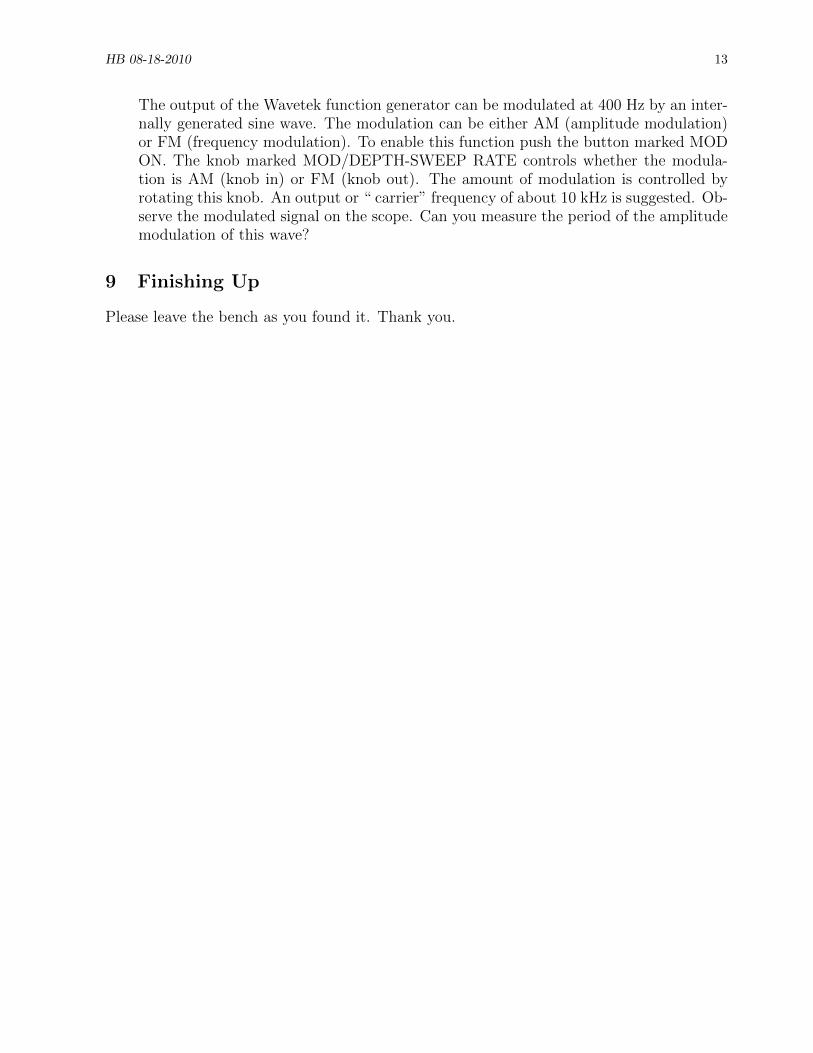
The voltage VT is the trigger voltage. It is the value of the voltage that tells the electronbeam to start the beginning of the curve. The horizontal time scale of the curve is equivalentto how fast the electron beam is swept across the phosphor. This is determined by the “timebase” of the scope. If the voltage has a very high frequency the time base needs to sweepthe electron beam across the phosphor quickly. A good scope can display voltages withfrequencies in the MHz range. If the frequency is not high, the electron beam needs to moveacross the phosphor slowly. By varying the time base it is possible to put many cycles of thevoltage on the scope or just part of one cycle.
The BK scope is actually capable of showing two traces (known as a dual trace or 2channel scope). When used this way one can input two voltages and observe how each inputvoltage produces its own trace. In later experiments you will see how useful this featurecan be. The BK scope can also be used as an x-y scope. When used this way, one inputvoltage is applied to the vertical deflection plates and the other input voltage is applied tothe horizontal deflection plates. The trace then shows the plot of one voltage against theother. For the time being we will not discuss these two capabilities and will use the BKscope as a single trace scope with the horizontal deflection voltage supplied by the scope.
HB 08-18-2010 3
3 Description of How a Scope Displays a Single Periodic Voltage
A periodic function in time is one that repeats itself again and again, such as a sine waveor a square wave. A scope can display a voltage that is periodic in time in exactly the sameway. The periodic voltage is connected to the vertical input of the scope, and if the scope isadjusted correctly, a graph of the voltage as a function of time appears as a stationary traceon the screen of the scope.
The ramp voltage that is applied to the horizontal deflection plates of the scope is usuallysupplied by the TIME BASE oscillator unit of the scope. We consider that case here. (Ifthe scope has “X-Y” capability the voltage to the horizontal deflection plates can also besupplied from an external voltage source.)
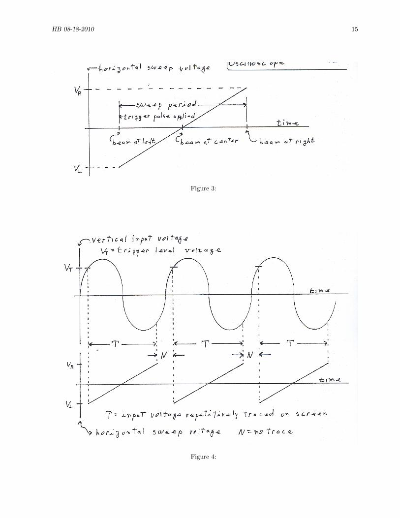
Every scope has a signal generator or time base oscillator. This oscillator produces avoltage that is a linear ramp as a function of time. Fig. 3 shows the ramp voltage for onesweep of the electron beam. This linear ramp, when applied to the horizontal deflectionplates, sweeps the electron beam from the left side of the screen to the right side of thescreen. When the ramp voltage across the horizontal deflection plates is VL, the electronbeam is at the left of the screen. When the ramp voltage is zero the beam is in the horizontalcenter of the screen. When the ramp voltage is VR the beam is at the right of the screen.We assume that |VL|=|VR|. How quickly the electron beam is swept across the screen iscontrolled by the TIME BASE switch.
In the most usual mode of operation, the voltage on the horizontal deflection plates isheld at VL and the electron beam is blanked (shut off). If a “trigger” pulse is applied to thecircuit (source of the trigger pulse discussed in a moment) the electron beam is turned onand the time base oscillator applies the ramp to the horizontal deflection plates. The inputvoltage is applied to the vertical deflection plates. See Fig. 4. The electron beam is sweptacross the screen from left to right at a constant speed. This takes a time P. At the sametime the vertical deflection of the electron beam is proportional to the input voltage. A spotof light is observed to move across the screen if the sweep speed is slow enough. This spotof light traces the input voltage for a time P. If the sweep speed is fast the trace will be toofaint to see unless many sweeps executing the same trace are made. When the ramp reachesVR the electron beam and the light spot reach the right side of the screen. The sweep voltageis then very quickly returned to VL. During this process the electron beam is shut off or“blanked” so that a return trace is not seen. For a stationary trace to be properly observedthe trigger pulses must all occur at similar points of the input voltage waveform. Thosesimilar points are taken to be the same voltage and the same slope of the input voltage.
The trigger pulses, the pulses that start the sweep voltage, can be derived from one of thefollowing signals. The only one of these signals that is relevant to this lab is the first one.
1. the input voltage, which is the voltage whose waveform you are interested in examin-ing. This is the voltage, which after suitable amplification or attenuation by the scopeelectronics, is applied to the vertical deflection plates.
2. the line voltage (110 V AC wall outlet). This may be a good choice if you know thatyour input signal is “synchronized” with the line voltage. The line voltage as a sourceof trigger pulses is not used in this lab.
3. some other “external” voltage that is not the line voltage but that you think is syn-chronized with your input signal. This capability is not used in this experiment.
HB 08-18-2010 4
We consider the case where the trigger pulse is derived from the input voltage, which is thevoltage that is to be observed. The operator of the scope, by using a scope control usuallymarked “trigger level”, chooses a value of the input voltage at which the trigger pulse isto occur. We call this voltage VT . This can be a positive or negative voltage, but for thetrigger pulse to occur VT must be between between the maximum and minimum values ofthe input voltage. If it is not, the trigger pulse will not occur. The scope operator can alsochoose whether the trigger pulse occurs when the slope of the input voltage (with respectto time) is positive or negative. Look at Fig. 4, which shows a sinusoidal input voltageand the horizontal sweep voltage as a function of time. The trigger voltage VT has beenchosen as positive. The triggering slope has also been chosen as positive. Fig. 4 shows thatwhenever the input voltage has a positive slope and reaches the value VT , a trigger pulse isproduced and the ramp voltage produced by the scope sweeps the electron beam horizontallyacross the screen at a rate determined by the TIME BASE. In Fig. 4 the time it takes forthe electron beam to go from the left side of the screen to the right side of the screen isdesignated by “P.” It does this repetitively, always starting at the “same” point of the inputvoltage and always tracing out the same curve. The result is a stationary trace of the inputvoltage on the scope screen. In the example shown in Fig. 4, note that somewhat less thanone cycle of the input voltage will be displayed. During the time intervals “N” the electronbeam is blanked and is not being swept across the phosphor. An additional point is thatonce a sweep starts it is always completed, even if the trigger conditions are met during thesweep. This allows the use of a low enough sweep speed so that a number of cycles of theinput waveform can be displayed on the screen.
You should understand the following statements. If you do not, please reread and studythe previous material.
• For a given input signal, if the electron horizontal sweep speed is increased, less of theinput waveform or fewer cycles will be displayed.
• If the electron horizontal sweep speed is decreased, more of the input waveform or morecycles will be displayed.
• If the trigger voltage VT is changed, the trace of the input voltage can be shifted left orright in a continuous fashion (exclude the square wave).
• If the trigger voltage VT is kept constant but the trigger slope is changed, the trace willbe shifted left or right. For example, Fig. 4 is drawn for triggering to occur on a positiveslope of the input voltage. If VT is kept the same but triggering were set to occur onthe negative slope of the input signal, at what points of the input signal in Fig. 4 mighttriggering occur? How about a negative VT and positive slope? A negative VT and anegative slope?
• Fig. 4 shows plots of three ramp or sweep voltages. A given ramp voltage, no matterwhich of the three plots it is associated with, corresponds to the same horizontal positionof the electron beam on the screen.
4 BK Controls for Single Trace Use
This section describes the controls (knobs and switches) and connectors (jacks) of the BKscope for single trace use. In what follows, we will use controls to mean knobs, switches,
HB 08-18-2010 5
buttons, connectors, etc. The controls that are used mainly for dual trace or x-y use willnot be discussed other than to adjust them for single trace use. There are a lot of controls,and unless you have a physical picture of what the controls do you will not be able to usethe scope in a reasonable sort of way. Review the previous section and Fig. 1 as necessary.
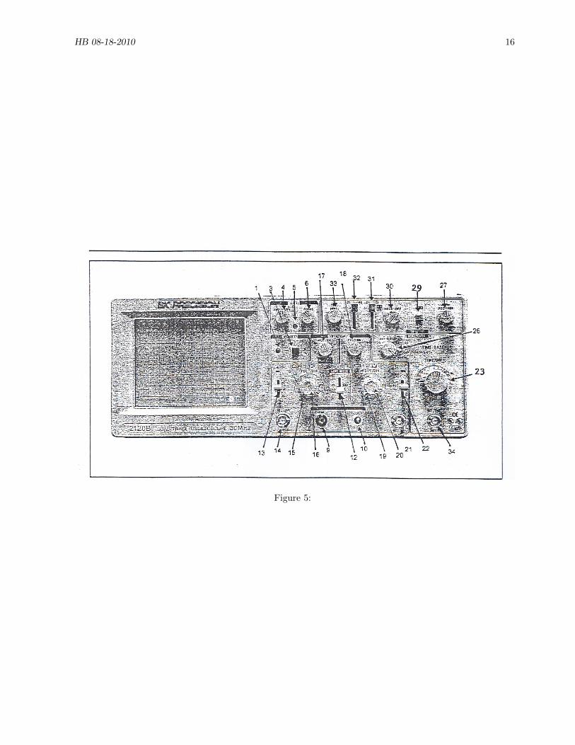
Fig. 5 is a picture of the front panel of the BK scope. The controls are numbered. Theparagraphs that follow shortly are numbered according to the control being described.
At the left in Fig. 5 is the screen where the trace appear. On the right are the controls.The controls are grouped in “boxes” according to function. All the boxes are named in Fig. 5except the one containing items 9 and 10, which below is called GND and CAL. The boxesare listed below along with the general function of the controls in each box. After the nameof the box, in parentheses, are the numbers of the controls that appear in that box. As youread, identify the boxes in Fig. 5. The box names are hard to read; the numbers are not.
“FUNCTION” BOXES OF BK SCOPE(Numbers in parentheses refer to the controls in the box)
• POWER(1,3)-Button (3) turns the scope on and off. LED (1) indicates when the scopeis on.
• CRT(4-6) (cathode ray tube)- controls the intensity and focus of the electron beam,and the sharpness of the trace.
• GND and CAL(9-10)- This box is not named but provides a calibration voltage andground. These will not be used in this lab.
• VERTICAL(12-22)- This box is really divided into two boxes. The scope has two voltageamplifiers for two possible input voltages. Recall that these voltages are applied to thevertical deflection plates which is why these controls appear in the “vertical” box. Thecontrols for the gain of these amplifiers are in this box, channel 1 on the left andchannel 2 on the right. In this box are also controls for moving the traces up and down,and for choosing single trace, dual trace, and x-y modes. There are also two connectorsfor possible input voltages.
• HORIZONTAL(time base)(23, 26, 34)- Control the rate at which the horizontal deflec-tion voltage is changed.
• TRIGGER(27, 29-33)- The ramp voltage that sweeps the electron beam horizontallyacross the screen has to be told when to start. Rotating knob (33) enable you to selectVT . If knob (33) is in, the trigger pulse occurs on a positive slope of the input signal. Ifthis knob is out the trigger pulse occurs on a negative slope of the input signal. Knob(27) moves the trace left and right.
There are a lot of knobs, switches, and connectors. If you keep the boxes in mind, andthe function of the controls in each box, you will be able to find the control(s) you needexpeditiously. The controls, numbered in Fig. 2, are now discussed, along with the initialsettings you should give them. The push button switches toggle between in and out. Thesebuttons should only be pushed (not pulled). Missing numbers are for controls not presenton model 2120B.
As you read through this list it tells you to set some controls at certain values or positions.Be sure to do this so that when you turn the scope on you see a trace. With a strange scopejust finding a trace can be difficult!
HB 08-18-2010 6
1. ON indicator. Lights when scope is on.
3. POWER pushbutton. Turns scope on and off. Leave scope off (button out).
4. INTENSITY control knob. Adjusts the current in the electron beam and therefore thebrightness of the trace. Set pointer up.
5. Trace rotation. Do not adjust.
6. FOCUS control knob. Adjusts trace focus. Set pointer up.
9. Ground. Not used in this lab.
10. Calibrate. Provides a 2 V p-p 1 kH calibration square wave. Not used in this lab.
12. VERTICAL MODE switch. Set to CH1 (channel 1 or X input).
13. CH1 AC-GND-DC switch. Set this switch at AC. This puts a blocking capacitor in theinput to the scope, suitable for AC signals. If in the future you wish to look at DC signals,choose DC. The GND position disconnects the input signal and grounds the scope input.This is very useful if you want to know what vertical position of the trace corresponds tozero volts.
14. CH1 INPUT JACK. Connect the signal you wish to examine to this jack. The jack is afemale Baby Type N connector, or BNC connector.
15. CH1 VOLTS/DIV control. This is the vertical sensitivity control for channel 1 anddetermines the amount of amplification applied to the input signal before the input signal isconnected to the vertical deflection plates. It is the larger of two knobs that are concentric.(The smaller knob is control 16.) The setting of this knob gives the vertical deflection ofthe trace for a particular input signal if the CH1 VARIABLE/PULL control (control 16) isfully clockwise in the CAL position and is in the “IN” position. For example, if this controlis set at 50 mV, a 100 mV input signal will produce a 2 cm vertical deflection of the traceif control 16 is “IN” and fully clockwise in the CAL position. Set at 1 V.
16. CH1 VARIABLE/PULL control. This is a variable vertical sensitivity control for chan-nel 1. It should be fully clockwise in the CAL position if you wish to use the markings forcontrol 15. This control can also be pulled out to increase the vertical sensitivity by a factorof 5. For now, be sure the knob is in and fully clockwise in the CAL position.
17. CH1 POSITION control. Moves the trace vertically. Set the pointer up. This knob canalso be pulled out. Be sure that it is in.
18. CH2 POSITION control. Adjusts the vertical position of the channel 2 trace if there isone. CH2 is not used in this lab.
19. CH2 VOLTS/DIV control. Adjusts the vertical sensitivity for channel 2 in fixed amounts.
HB 08-18-2010 7
20. CH2 VARIABLE/PULL control. Adjusts the vertically sensitivity of channel 2 contin-uously.
21. CH2 INPUT JACK. Not needed in this lab.
22. CH2 AC-GND-DC switch. Not needed in this lab, but set at GND.
23. Horizontal TIME/DIV control. Adjusts the rate, in discreet steps, at which the electronbeam is swept across the screen. For the numbers to be valid, control 26 (VAR SWEEP)must be in the CAL position. For example, if this control is set a 5 ms, the horizontal sweepvoltage will move the electron beam across the screen a distance of 1 cm in 5 ms if control26 is in the CAL position (fully CW). Set this control for 1 ms.
26. VARIABLE SWEEP control. Provides for variable adjustment of horizontal sweep rate.When this control is in the CAL position, control 23 is calibrated. Set in CAL position (fullyclockwise).
27. HORIZONTAL POSITION/PULL control. Adjusts the horizontal position of the trace.Set pointer up. This control knob can be pulled out to expand the trace horizontally. Setthe knob in.
29. X-Y button. This button should be out. (button is “in” for x-y operation.)
30. HOLDOFF/PULL CHOP control. Check that this knob is in and full counterclockwise.
31. Trigger SOURCE switch. Selects the signal from which the trigger pulse is derived. Setat CH 1 (CH=channel).
32. Trigger COUPLING switch. In the AUTO mode, a sweep voltage is generated and atrace appears whether or not there is an appropriate signal for the scope to trigger on. Inthe NORMAL mode, a trigger pulse and trace are only generated if the input voltage has avalue that satisfies the trigger voltage level chosen. With a strange scope it is often difficultto find a trace. For this reason, set this control at AUTO.
33. TRIGger LEVEL/PULL(-)SLOPE. Adjusts the trigger level voltage, VT . Set knobpointer up, which is approximately VT = 0. When knob is in, scope triggers on positiveslope of signal. When knob is out, scope triggers on negative slope of input signal. Set knobin for positive slope triggering.
34. External Trigger. The connector at which an external trigger signal is fed into the scope.Not used in this lab.
5 Using The BK Oscilloscope
In this section the BK scope is used to examine various AC voltages. You will be ableto “see” how the voltage depends on time, measure the amplitude at various times, andmeasure times between different points on the voltage vs time curve. It will probably be
HB 08-18-2010 8
helpful to refer to previous sections during these exercises. Reminder: the VOLTS/DIV andTIME/DIV switches are not calibrated unless the knobs in the center of these switches arefully clockwise in the calibrated positions.
5.1 Preliminaries
Remove any input cables to the scope. Turn on the scope (control 3) and observe LED (1).In a few seconds you should see a trace which is a horizontal line (it takes the cathode afew seconds to warm up). If you do not, check your initial control settings. Adjust theINTENSITY (4) and FOCUS (6) controls for a sharp trace which is easy to view but notbrighter than necessary. Too bright is hard on the phosphor. Move the trace about thescreen with the 2 POSITION controls, 17 (vertical) and 27 (horizontal). Leave the tracecentered. Turn the time base switch (23) to 0.2 s and note the light spot move slowly acrossthe screen until it gets to the right hand side of the screen. What happens then? Investigatethe effect of turning the variable sweep rate knob (26). Increase the sweep speed one clickat a time and note how the moving spot becomes a solid line. Observe that there is a rangeof sweep speeds for which the trace “flickers.” This is due to the persistence of the phosphoror of the human eye, or perhaps both.
When you need to make measurements of an input signal (peak voltage, period, etc.), itis useful to use the two position controls (17, 27) to move parts of the trace onto the gridlinesof the screen that have finer divisions.
Try setting the Trigger COUPLING switch (32) to NORMal. The trace should disappear,as there is no input signal for the scope to trigger on. Set this switch back to AUTO toretrieve the trace.
5.2 Observing Voltage From The Wavetek FG3C Function Generator
This function generator produces sine, square and triangular waveforms which are selectedby three pushbuttons. The frequency of these waveforms can be adjusted from 0.3 Hz to3 MHz by means of a knob marked frequency and 7 pushbuttons. The output frequencyappears in the middle of the display panel. At the bottom of the display panel to the rightappear Hz, and in the middle of the bottom there may a multiplier for Hz such as k orM. It is important to check for the k or M to determine whether the stated frequency isin kHz or MHz. The multiplier appears and vanishes automatically as you cross certainthreshold frequencies such as 1 kHz. The amplitude of the output is varied by a knob atthe right marked AMPL. The knobs have “in” and “out” positions. The functions for theknobs are marked in black for the “in” position and blue for the “out” position. In usingthis instrument as a simple function generator be sure all the knobs at the bottom of thefront panel are in and that the only two green LED’s that are on are one for the waveformchosen and one for the frequency range (buttons at top).
Connect the 50 Ω output of this oscillator to the CH1 vertical input (14) of the BK scopeusing the coaxial cable. Set the AMPL knob full CCW and turn on both the oscillator andscope. Adjust the Wavetek for about a 1 kHz sine wave and turn the AMPL knob CW untilyou see a reasonable signal.
Vary all of the controls listed below leaving the parameters of the input voltage constant.Note the effect on the trace of varying a control and understand why the trace changes inthe way it does. In answering the following questions make sketches of a trace if it will helpyour explanation. How does the trace change if:
HB 08-18-2010 9
1. the VOLTS/DIV controls are changed (15 and 16)?
2. the TIME/DIV controls are changed (23 and 26)?
3. the trigger level (33) voltage is changed (33)? Note that if the trigger voltage is set toohigh or too low the trace does not “freeze” but “runs” to the right or the left if thetrigger coupling switch is on AUTO.
4. With the trigger COUPLING switch in the NORMal mode, can you make the tracedisappear by rotating the TRIG LEVEL knob (33) both ways? Explain.
5. the triggering slope is changed from + to − (pull control 33).
6. the position controls 17 and 27 are changed?
The controls you have just used are the ones most frequently employed in adjusting thetrace.
It is instructive to look at a low frequency signal from the Wavetek oscillator. If thefrequency is appropriate, the time development of a trace as shown in Fig. 4 can be followed.Set the frequency of the Wavetek oscillator to about 5 Hz and the time base to 50 ms.Observe the development of the trace carefully and note the effect of changing the triggerparameters. Change the sweep speed one click to 20 ms and increase the frequency of theWavetek function generator until about the same number of cycles appear on the scope.Keep doing this until the trace becomes continuous.
5.3 Other Waveforms and Functions
• Observe square and triangular waveforms from the Wavetek by pushing the appropriatebuttons. The frequency is not critical, but around 1 kHz works well.
• Look at all the waveforms and observe what happens to the waveforms when you pullout the Wavetek knob marked DUTY (short for duty cycle) and rotate the knob CWand CCW. Push in the DUTY knob.
• Pull out the Wavetek OFFSET knob. Change the CH1 AC-GND-DC (13) switch fromAC to DC and rotate the OFFSET knob. What does the trace do? What does thetrace do if you change back to AC? Can you figure out how to measure the amount ofDC bias a periodic signal has? (The DC bias of a voltage signal is its average value.)
5.4 Maximum Input Voltage
An important specification of a scope is the maximum input voltage that is permitted. Forthe BK scope this is ± 400 V. A small AC voltage riding on a large DC voltage can beexamined by putting the input switch (13) on AC. The average voltage of the input voltageis removed by the input capacitor and the gain of the scope can be utilized to vet the ACpart of the signal.
5.5 Measuring Waveform Parameters
A useful function of a scope is to measure the peak to peak voltage and period of a voltagewaveform. Display a 1 kHz triangular wave on the scope. Controls 16 and 26 must be fullyCW in their calibrated positions. Adjust the other controls so that vertically the trace takes
HB 08-18-2010 10
up most of the screen and horizontally there is about one cycle of the input waveform on thescreen. Use the calibration of the VOLTS/DIV control and the horizontal grid lines on thescreen to determine the peak to peak voltage of the triangular wave. Use the calibration ofthe TIME/DIV control and the vertical grid lines on the screen to determine the period ofthe wave. For both of these measurements judicious use of both the horizontal and verticalposition controls will enable you to utilize the finer markings on some of the grid lines of thescreen. The amplitude of the output of the Wavetek is not calibrated. You are using thescope to measure this amplitude. The frequency output of the Wavetek is calibrated andyou should compare the Wavetek’s stated frequency with your period measurement.
5.6 Scope Probes
In this experiment the function generator is connected to the scope by a cable with connectorson both ends. Very often, voltages in a circuit are of interest and a scope probe is used. Thisis a cable with a connector on one end for plugging into the scope input. The other end ofthe probe cable has an electrode for touching the point in the circuit whose voltage waveformis desired. There is a clip for making a connection to ground. Probes often attenuate thesignal by a factor of 10 or a 100, but if they do, the resistance loading they present to thecircuit increases by a factor of 10 or a 100. Remember that in connecting a voltage measuringdevice to a circuit, the higher the resistance of this device, the better. A probe is not usedin this lab.
6 Using The SWS Oscilloscope
One of the displays available with SWS is the oscilloscope. This is not actually an oscilloscopebut software that closely mimics an oscilloscope. In some respects the SWS scope is a morepowerful diagnostic tool than the BK scope. In particular:
1. There are 3 vertical inputs each of which has its own trace. (Three voltages can beobserved simultaneously as a function of time.) The 3 traces have different colors. Theinput for each trace is selected by an input menu button.
2. This scope is a storage scope. When you stop monitoring data the last trace is storedfor further use.
3. There is a smart cursor which is used in a similar way as in the graph display.
On the other hand, the BK scope is a much faster scope. The highest frequency you canexamine with the BK scope is 30 MHz. With the SWS scope the highest frequency is 10 kHz.The other main difference between using the BK and SWS scopes is that in the SWS scopethe controls are icon buttons, and a slider is used for the trigger level and slope. See page178 of the SWS manual for a description of adjusting the trigger level and slope. The picturein the manual does not show this slider adequately. It is a small triangle in a vertical stripat the very left of the scope screen. The default trigger voltage is 0 with positive slope.
There are only 2 trigger options in the SWS scope. The default is with the button atthe bottom of the scope display labeled TRIG in the in position. In this mode there mustbe an appropriate input signal for a trace to be observed. This corresponds to NORMALfor control 32 of the BK scope. If you are having trouble finding a trace, click the TRIGbutton. With this button “out” the time base oscillator is free running and does not need
HB 08-18-2010 11
trigger pulses to produce a trace. This corresponds to AUTO for control 32 of the BK scope.A difference here that that the TRIG button must be in to freeze the trace with the SWSscope.
In using the SWS scope display, use MON rather than REC. An enormous amount ofdata flows from the scope and if you use REC the storage capacity of SWS will be overtaxed.
6.1 Voltage From 750 Interface
In this section voltages from the SWS signal generator will be examined with the SWS scope.In the right experiment setup window click the sample V button to open the signal generatorwindow. Click auto. Drag the scope display icon to the terminals labeled V to open thescope display. Observe the different signals from the signal generator with the scope displayand thoroughly familiarize yourself with the controls of the SWS scope.
You may have trouble getting a trace with the 3 positive only waveforms from the SWSsignal generator. This may be due to the fact that the default trigger level is 0. Try adjustingthe trigger level for a slightly positive voltage.
A nice feature of the SWS scope is the Smart Cursor. With a good stable trace investigateinvestigate this capability.
6.2 SWS Scope and the Voltage Sensor
If you are using the SWS scope to measure voltages in a circuit, use the voltage sensor. Toset this up, drag the scope icon to the voltage sensor icon. The voltage censor is not used inthis lab.
6.3 Lissajous Patterens
Up to now both scopes have been used in the time base mode. In this mode the voltageapplied to the horizontal deflection plates is generated internally in the scope. Both the BKand the SWS scopes have two-dimensional capability in the X-Y plane. When sine wavesare applied to both the vertical and horizontal inputs of a 2-D scope the resulting trace iscalled a Lissajous curve. The form of the curve depends on the frequency ratio and phasedifference of the 2 signals. If the frequency ratio is a rational fraction the curve is closed.Observe a 5 V 500 Hz Sine wave from the SWS signal generator on the SWS scope in the timebase mode. Click STOP. Click the X-axis input menu button and apply the SWS sine wavesignal to the X-axis of the scope. Use 2 V/div on both the X and Y axes. (Note that withrespect to the X-axis controls of the scope, the 2 buttons that controlled the sweep rate inthe time base mode now control the horizontal gain and are labeled V/div.) What curve doyou see on the screen? What happens if the V/div is changed on one axis? Explain. Leavethe SWS signal on the Y axis of the scope. Use a voltage sensor to input the voltage fromthe Wavetek oscillator to the interface. Apply this signal to the X-axis of the SWS scope,adjusting the X-axis amplification if necessary. Try the frequencies of 500Hz, and multiplies3/2, 2, etc of that frequency. See if you can get closed curves. It will be impossible to getsteady closed curves because of the frequency and phase drifts between the 2 oscillators butit should be possible to freeze transient pictures of Lissajous curves by clicking STOP.
HB 08-18-2010 12
7 Analog versus Digital Scopes
In an analog scope the input voltage, after amplification or attenuation, is applied to thevertical deflection plates of the scope. The scope trace is smooth. In a digital scope, suchas the SWS scope, the input signal is sampled at the “sampling rate” and the scope trace isthese values usually connected by straight lines. You may have noticed this fact in looking atthe SWS scope trace. One of the important specifications for a digital scope is its samplingrate, which may be hundreds of kHz or higher. This number is the maximum sampling rateand is the rate used at the highest sweep speeds. In reality, the actual sampling rate is lowerand is usually adjusted so that there are about a few hundred to a thousand samples persweep. If the sampling rate is not high enough severe distortion of the signal can result. Toget a reasonable portrayal of the signal the sampling rate should be at least ten times thefrequency of the signal.
In the SWS scope the sampling rate is adjusted automatically and is displayed at thebottom of the scope near the Trigger button and sweep speed. For the SWS scope determinethe sampling rate for a sweep speed of 1 ms/div and then calculate the samples per sweep.A div or division is a large division as indicated by extended lines on the graticule.
A digital scope is often a storage scope. The sampled voltages are stored and the tracesviewed after the input voltage has ceased to be sampled. In an analog scope the trace willdisappear once the signal is no longer applied to the scope.
8 Optional Exercises- NO Credit
If you fully understand the operation of the scope and have extra time, feel free to explore twoadditional features of the Wavetek generator; sweep and modulation. Look at the waveformson the scope and adjust the controls so as to highlight the features of these waves. Althoughyou can use any waveform you want, it is suggested that you start with sine waves and withsetting of the TIME/DIV control of 1 ms.
• SWEEP In the sweep mode, the wavetek repetitively sweeps from a lower frequency toa higher frequency. Set the frequency knob of the Wavetek at about 1 kHz and pull outthis knob to start the sweep function. The higher frequency is selected by this knob.You will find that the two knobs labeled SWEEP TIME and MOD/DEPTH-SWEEPRATE affect the waveform. Can you figure out exactly what these knobs do? Does itmake any difference whether these knobs are in or out? When you are finished, put thefrequency knob back in.
• MODULATION A “carrier (wave)” is a single frequency (sinusoidal) electromagneticwave. For radio broadcasting in the U.S. the carrier frequencies for AM stations liebetween 520 and 1610 kHz, and the carrier frequencies for FM stations lie between87.5 and 108.0 MHz. Information, such as speech or music, has to be encoded on thecarrier wave. The process of encoding the information is called modulation. Whenthe amplitude of the carrier wave is varied it is called amplitude modulation or AM.When the frequency of the carrier wave is varied it is called frequency modulationor FM. Modulation at a single frequency corresponds to a pure tone. For example,broadcasting “middle C” would require a sinusoidal modulation of about 261.6 Hz forboth AM and FM stations.
HB 08-18-2010 13
The output of the Wavetek function generator can be modulated at 400 Hz by an inter-nally generated sine wave. The modulation can be either AM (amplitude modulation)or FM (frequency modulation). To enable this function push the button marked MODON. The knob marked MOD/DEPTH-SWEEP RATE controls whether the modula-tion is AM (knob in) or FM (knob out). The amount of modulation is controlled byrotating this knob. An output or “ carrier” frequency of about 10 kHz is suggested. Ob-serve the modulated signal on the scope. Can you measure the period of the amplitudemodulation of this wave?
9 Finishing Up
Please leave the bench as you found it. Thank you.
HB 08-18-2010 14
Figure 1:
Figure 2:
HB 08-18-2010 15
Figure 3:
Figure 4:
HB 08-18-2010 16
Figure 5: