Embed Size (px)
Citation preview
OS-9 Technical
User Manual
Copyright 1991 Microware Systems Corporation. All Rights Reserved.Reproduction of this document, in part or whole, by any means, electrical,mechanical, magnetic, optical, chemical, manual, or otherwise is prohib-ited, without written permission from Microware Systems Corporation.
Publication Editors: Walden Miller, Kathleen Flood, Debbie Baier Contributing Writers: Warren Brown, Richard YeatesRevision: JPublication date: March 1991Product Number: OST68NA68MO
The software described in this document is intended to be used on a singlecomputer system. Microware expressly prohibits any reproduction of thesoftware on tape, disk or any other medium except for backup purposes.Distribution of this software, in part or whole, to any other party or on anyother system may constitute copyright infringements and misappropriationof trade secrets and confidential processes which are the property ofMicroware and/or other parties. Unauthorized distribution of software maycause damages far in excess of the value of the copies involved.
For additional copies of this software and/or documentation, or if you havequestions concerning the above notice, the documentation and/or software,please contact your OS-9 supplier.
Microware, OS-9, and RAVE are registered trademarks of MicrowareSystems Corporation.
Microware Systems Corporation • 1900 N.W. 114th Street Des Moines, Iowa 50325-7077 • Phone: 515/224-1929
Copyright and RevisionHistory
Disclaimer
Trademarks
Preface
i
Introduction
The OS-9 Technical User Manual is organized into two main sections:The OS-9 Technical Overview is covered in chapters 1 through 7 andAppendix A, B and C; OS-9 System Calls is covered in Appendix D.
The OS-9 Technical Overview contains the following chapters andappendices:
Chapter 1 – System OverviewProvides a general overview of OS-9’s four levels of modularity, I/Oprocessing, memory modules, and program modules.
Chapter 2 – The KernelOutlines the responsibilities of the kernel. Explains user and systemstate processing, memory management, system initialization, processcreation and scheduling, and exception and interrupt processing.
Chapter 3 – OS-9 Input/Output SystemExplains the software components of the OS-9 I/O system and therelationships between those components.
Chapter 4 – Interprocess CommunicationsDescribes the five forms of interprocess communication supported byOS-9: signals, alarms, events, pipes, and data modules.
Chapter 5 – User Trap HandlersExplains how to install and execute trap handlers, and provides anexample of trap handler coding.
Chapter 6 – The Math ModuleDiscusses math module functions, and lists descriptions of the assemblercalls you can use with the math module.
Chapter 7 – RBF File SystemExplains OS-9’s disk file organization, raw physical I/O on RBFdevices, record locking, and file security.
Manual Organization

Preface
ii
Appendix A – Example CodeContains example code that you can use as a guide when creating your own modules. Provides examples of RBF, SCF, and SBF device descriptors.
Appendix B – Path Descriptors and Device DescriptorsIncludes the device descriptor initialization table definitions and path descriptor option tables for RBF, SCF, SBF, and PIPEMAN type devices.
Appendix C – OS-9 System Calls contains descriptions for thefollowing types of system calls:
User-State System Calls I/O System Calls System-State System Calls
The OS-9 Technical User Manual is designed for you to use in conjunctionwith the OS-9 Technical I/O User Manual.
OS-9 Technical User ManualTable of Contents
I
Chapter 1
System Modularity 1-1. . . . . . . . . . . . . . . . . . . . . . . . . . . . . . . . . . . . . . . . . . I/O Overview 1-3. . . . . . . . . . . . . . . . . . . . . . . . . . . . . . . . . . . . . . . . . . . . . . .
Chapter 2
Responsibilities of the Kernel 2-1. . . . . . . . . . . . . . . . . . . . . . . . . . . . . . . . . . System Call Overview 2-1. . . . . . . . . . . . . . . . . . . . . . . . . . . . . . . . . . . . . . . . Memory Management 2-5. . . . . . . . . . . . . . . . . . . . . . . . . . . . . . . . . . . . . . . . System Initialization 2-12. . . . . . . . . . . . . . . . . . . . . . . . . . . . . . . . . . . . . . . . . Process Creation 2-18. . . . . . . . . . . . . . . . . . . . . . . . . . . . . . . . . . . . . . . . . . . . Process Scheduling 2-22. . . . . . . . . . . . . . . . . . . . . . . . . . . . . . . . . . . . . . . . . . Exception and Interrupt Processing 2-24. . . . . . . . . . . . . . . . . . . . . . . . . . . . . .
Chapter 3
The OS-9 Unified Input/Output System 3-1. . . . . . . . . . . . . . . . . . . . . . . . . . The Kernel and I/O 3-2. . . . . . . . . . . . . . . . . . . . . . . . . . . . . . . . . . . . . . . . . . File Managers 3-6. . . . . . . . . . . . . . . . . . . . . . . . . . . . . . . . . . . . . . . . . . . . . . Device Driver Modules 3-10. . . . . . . . . . . . . . . . . . . . . . . . . . . . . . . . . . . . . . .
Chapter 4
Signals 4-1. . . . . . . . . . . . . . . . . . . . . . . . . . . . . . . . . . . . . . . . . . . . . . . . . . . . Alarms 4-3. . . . . . . . . . . . . . . . . . . . . . . . . . . . . . . . . . . . . . . . . . . . . . . . . . . . Events 4-6. . . . . . . . . . . . . . . . . . . . . . . . . . . . . . . . . . . . . . . . . . . . . . . . . . . . Pipes 4-8. . . . . . . . . . . . . . . . . . . . . . . . . . . . . . . . . . . . . . . . . . . . . . . . . . . . . Data Modules 4-13. . . . . . . . . . . . . . . . . . . . . . . . . . . . . . . . . . . . . . . . . . . . . . .
Chapter 5
Trap Handlers 5-1. . . . . . . . . . . . . . . . . . . . . . . . . . . . . . . . . . . . . . . . . . . . . . Installing and Executing Trap Handlers 5-2. . . . . . . . . . . . . . . . . . . . . . . . . . OS-9 and tcall: Equivalent Assembly Language Syntax 5-2. . . . . . . . . . . . . . Calling a Trap Handler 5-3. . . . . . . . . . . . . . . . . . . . . . . . . . . . . . . . . . . . . . . An Example Trap Handler 5-5. . . . . . . . . . . . . . . . . . . . . . . . . . . . . . . . . . . . . Trace of Example Two Using the Example Trap Handler 5-8. . . . . . . . . . . .
System Overview
The Kernel
OS-9 Input/Output System
InterprocessCommunications
User Trap Handlers

OS-9 Technical User ManualTable of Contents
II
Chapter 6
The Standard Function Library Module 6-1. . . . . . . . . . . . . . . . . . . . . . . . . . Calling Standard Function Module Routines 6-2. . . . . . . . . . . . . . . . . . . . . . Data Formats 6-2. . . . . . . . . . . . . . . . . . . . . . . . . . . . . . . . . . . . . . . . . . . . . . . The Math Module 6-3. . . . . . . . . . . . . . . . . . . . . . . . . . . . . . . . . . . . . . . . . . . T$Acs 6-5. . . . . . . . . . . . . . . . . . . . . . . . . . . . . . . . . . . . . . . . . . . . . . . . . . . . T$Asn 6-6. . . . . . . . . . . . . . . . . . . . . . . . . . . . . . . . . . . . . . . . . . . . . . . . . . . . T$Atn 6-7. . . . . . . . . . . . . . . . . . . . . . . . . . . . . . . . . . . . . . . . . . . . . . . . . . . . . T$AtoD 6-8. . . . . . . . . . . . . . . . . . . . . . . . . . . . . . . . . . . . . . . . . . . . . . . . . . . T$AtoF 6-9. . . . . . . . . . . . . . . . . . . . . . . . . . . . . . . . . . . . . . . . . . . . . . . . . . . T$AtoL 6-10. . . . . . . . . . . . . . . . . . . . . . . . . . . . . . . . . . . . . . . . . . . . . . . . . . . T$AtoN 6-11. . . . . . . . . . . . . . . . . . . . . . . . . . . . . . . . . . . . . . . . . . . . . . . . . . . T$AtoU 6-12. . . . . . . . . . . . . . . . . . . . . . . . . . . . . . . . . . . . . . . . . . . . . . . . . . . T$Cos 6-13. . . . . . . . . . . . . . . . . . . . . . . . . . . . . . . . . . . . . . . . . . . . . . . . . . . . T$DAdd 6-14. . . . . . . . . . . . . . . . . . . . . . . . . . . . . . . . . . . . . . . . . . . . . . . . . . . T$DCmp 6-15. . . . . . . . . . . . . . . . . . . . . . . . . . . . . . . . . . . . . . . . . . . . . . . . . . T$DDec 6-16. . . . . . . . . . . . . . . . . . . . . . . . . . . . . . . . . . . . . . . . . . . . . . . . . . . T$DDiv 6-17. . . . . . . . . . . . . . . . . . . . . . . . . . . . . . . . . . . . . . . . . . . . . . . . . . . T$DInc 6-18. . . . . . . . . . . . . . . . . . . . . . . . . . . . . . . . . . . . . . . . . . . . . . . . . . . . T$DInt 6-19. . . . . . . . . . . . . . . . . . . . . . . . . . . . . . . . . . . . . . . . . . . . . . . . . . . . T$DMul 6-20. . . . . . . . . . . . . . . . . . . . . . . . . . . . . . . . . . . . . . . . . . . . . . . . . . . T$DNeg 6-21. . . . . . . . . . . . . . . . . . . . . . . . . . . . . . . . . . . . . . . . . . . . . . . . . . . T$DNrm 6-22. . . . . . . . . . . . . . . . . . . . . . . . . . . . . . . . . . . . . . . . . . . . . . . . . . T$DSub 6-23. . . . . . . . . . . . . . . . . . . . . . . . . . . . . . . . . . . . . . . . . . . . . . . . . . . T$DtoA 6-24. . . . . . . . . . . . . . . . . . . . . . . . . . . . . . . . . . . . . . . . . . . . . . . . . . . T$DtoF 6-25. . . . . . . . . . . . . . . . . . . . . . . . . . . . . . . . . . . . . . . . . . . . . . . . . . . T$DtoL 6-26. . . . . . . . . . . . . . . . . . . . . . . . . . . . . . . . . . . . . . . . . . . . . . . . . . . T$DtoU 6-27. . . . . . . . . . . . . . . . . . . . . . . . . . . . . . . . . . . . . . . . . . . . . . . . . . . T$DTrn 6-28. . . . . . . . . . . . . . . . . . . . . . . . . . . . . . . . . . . . . . . . . . . . . . . . . . . T$Exp 6-29. . . . . . . . . . . . . . . . . . . . . . . . . . . . . . . . . . . . . . . . . . . . . . . . . . . . T$FAdd 6-30. . . . . . . . . . . . . . . . . . . . . . . . . . . . . . . . . . . . . . . . . . . . . . . . . . . T$FCmp 6-31. . . . . . . . . . . . . . . . . . . . . . . . . . . . . . . . . . . . . . . . . . . . . . . . . . . T$FDec 6-32. . . . . . . . . . . . . . . . . . . . . . . . . . . . . . . . . . . . . . . . . . . . . . . . . . . T$FDiv 6-33. . . . . . . . . . . . . . . . . . . . . . . . . . . . . . . . . . . . . . . . . . . . . . . . . . . T$FInc 6-34. . . . . . . . . . . . . . . . . . . . . . . . . . . . . . . . . . . . . . . . . . . . . . . . . . . . T$FInt 6-35. . . . . . . . . . . . . . . . . . . . . . . . . . . . . . . . . . . . . . . . . . . . . . . . . . . . T$FMul 6-36. . . . . . . . . . . . . . . . . . . . . . . . . . . . . . . . . . . . . . . . . . . . . . . . . . . T$FNeg 6-37. . . . . . . . . . . . . . . . . . . . . . . . . . . . . . . . . . . . . . . . . . . . . . . . . . . T$FSub 6-38. . . . . . . . . . . . . . . . . . . . . . . . . . . . . . . . . . . . . . . . . . . . . . . . . . . T$FtoA 6-39. . . . . . . . . . . . . . . . . . . . . . . . . . . . . . . . . . . . . . . . . . . . . . . . . . . T$FtoD 6-40. . . . . . . . . . . . . . . . . . . . . . . . . . . . . . . . . . . . . . . . . . . . . . . . . . . T$FtoL 6-41. . . . . . . . . . . . . . . . . . . . . . . . . . . . . . . . . . . . . . . . . . . . . . . . . . . . T$FtoU 6-42. . . . . . . . . . . . . . . . . . . . . . . . . . . . . . . . . . . . . . . . . . . . . . . . . . . T$FTrn 6-43. . . . . . . . . . . . . . . . . . . . . . . . . . . . . . . . . . . . . . . . . . . . . . . . . . . . T$LDiv 6-44. . . . . . . . . . . . . . . . . . . . . . . . . . . . . . . . . . . . . . . . . . . . . . . . . . .
The Math Module

OS-9 Technical User ManualTable of Contents
III
Chapter 6 Continued
T$LMod 6-45. . . . . . . . . . . . . . . . . . . . . . . . . . . . . . . . . . . . . . . . . . . . . . . . . . . T$LMul 6-46. . . . . . . . . . . . . . . . . . . . . . . . . . . . . . . . . . . . . . . . . . . . . . . . . . . T$Log 6-47. . . . . . . . . . . . . . . . . . . . . . . . . . . . . . . . . . . . . . . . . . . . . . . . . . . . T$Log10 6-48. . . . . . . . . . . . . . . . . . . . . . . . . . . . . . . . . . . . . . . . . . . . . . . . . . T$LtoA 6-49. . . . . . . . . . . . . . . . . . . . . . . . . . . . . . . . . . . . . . . . . . . . . . . . . . . T$LtoD 6-50. . . . . . . . . . . . . . . . . . . . . . . . . . . . . . . . . . . . . . . . . . . . . . . . . . . T$LtoF 6-51. . . . . . . . . . . . . . . . . . . . . . . . . . . . . . . . . . . . . . . . . . . . . . . . . . . . T$Power 6-52. . . . . . . . . . . . . . . . . . . . . . . . . . . . . . . . . . . . . . . . . . . . . . . . . . T$Sin 6-53. . . . . . . . . . . . . . . . . . . . . . . . . . . . . . . . . . . . . . . . . . . . . . . . . . . . . T$Sqrt 6-54. . . . . . . . . . . . . . . . . . . . . . . . . . . . . . . . . . . . . . . . . . . . . . . . . . . . T$Tan 6-55. . . . . . . . . . . . . . . . . . . . . . . . . . . . . . . . . . . . . . . . . . . . . . . . . . . . . T$UDiv 6-56. . . . . . . . . . . . . . . . . . . . . . . . . . . . . . . . . . . . . . . . . . . . . . . . . . . T$UMod 6-57. . . . . . . . . . . . . . . . . . . . . . . . . . . . . . . . . . . . . . . . . . . . . . . . . . T$UMul 6-58. . . . . . . . . . . . . . . . . . . . . . . . . . . . . . . . . . . . . . . . . . . . . . . . . . . T$UtoA 6-59. . . . . . . . . . . . . . . . . . . . . . . . . . . . . . . . . . . . . . . . . . . . . . . . . . . T$UtoD 6-60. . . . . . . . . . . . . . . . . . . . . . . . . . . . . . . . . . . . . . . . . . . . . . . . . . . T$UtoF 6-61. . . . . . . . . . . . . . . . . . . . . . . . . . . . . . . . . . . . . . . . . . . . . . . . . . .
Chapter 7
Disk File Organization 7-1. . . . . . . . . . . . . . . . . . . . . . . . . . . . . . . . . . . . . . . . Raw Physical I/O on RBF Devices 7-6. . . . . . . . . . . . . . . . . . . . . . . . . . . . . . Record Locking 7-7. . . . . . . . . . . . . . . . . . . . . . . . . . . . . . . . . . . . . . . . . . . . . Record Locking Details for I/O Functions 7-9. . . . . . . . . . . . . . . . . . . . . . . . File Security 7-10. . . . . . . . . . . . . . . . . . . . . . . . . . . . . . . . . . . . . . . . . . . . . . . .
Appendix A
Introduction A-1. . . . . . . . . . . . . . . . . . . . . . . . . . . . . . . . . . . . . . . . . . . . . . . . Init Module A-1. . . . . . . . . . . . . . . . . . . . . . . . . . . . . . . . . . . . . . . . . . . . . . . . Sysgo Module A-5. . . . . . . . . . . . . . . . . . . . . . . . . . . . . . . . . . . . . . . . . . . . . . Signals: Example Program A-7. . . . . . . . . . . . . . . . . . . . . . . . . . . . . . . . . . . . Alarms: Example Program A-9. . . . . . . . . . . . . . . . . . . . . . . . . . . . . . . . . . . . Events: Example Program A-11. . . . . . . . . . . . . . . . . . . . . . . . . . . . . . . . . . . . . C Trap Handler A-13. . . . . . . . . . . . . . . . . . . . . . . . . . . . . . . . . . . . . . . . . . . . . RBF Device Descriptor A-18. . . . . . . . . . . . . . . . . . . . . . . . . . . . . . . . . . . . . . . SCF Device Descriptor A-23. . . . . . . . . . . . . . . . . . . . . . . . . . . . . . . . . . . . . . . SBF Device Descriptor A-25. . . . . . . . . . . . . . . . . . . . . . . . . . . . . . . . . . . . . . .
The Math Module
OS-9 File System
Example Code

OS-9 Technical User ManualTable of Contents
IV
Appendix B
Introduction B-1. . . . . . . . . . . . . . . . . . . . . . . . . . . . . . . . . . . . . . . . . . . . . . . . RBF Device Descriptor Modules B-1. . . . . . . . . . . . . . . . . . . . . . . . . . . . . . . RBF Definitions of the Path Descriptor B-7. . . . . . . . . . . . . . . . . . . . . . . . . . SCF Device Descriptor Modules B-9. . . . . . . . . . . . . . . . . . . . . . . . . . . . . . . . SCF Definitions of the Path Descriptor B-13. . . . . . . . . . . . . . . . . . . . . . . . . . . SBF Device Descriptor Modules B-15. . . . . . . . . . . . . . . . . . . . . . . . . . . . . . . . SBF Definitions of the Path Descriptor B-17. . . . . . . . . . . . . . . . . . . . . . . . . . . Pipeman Definitions of the Path Descriptor B-18. . . . . . . . . . . . . . . . . . . . . . .
Appendix C
IntroductionOS-9 System Call Descriptions C-1. . . . . . . . . . . . . . . . . . . . . . . . . . . . . . . . . User-state System CallsF$Alarm C-3. . . . . . . . . . . . . . . . . . . . . . . . . . . . . . . . . . . . . . . . . . . . . . . . . . . A$Delete C-4. . . . . . . . . . . . . . . . . . . . . . . . . . . . . . . . . . . . . . . . . . . . . . . . . . A$Set C-5. . . . . . . . . . . . . . . . . . . . . . . . . . . . . . . . . . . . . . . . . . . . . . . . . . . . . A$Cycle C-6. . . . . . . . . . . . . . . . . . . . . . . . . . . . . . . . . . . . . . . . . . . . . . . . . . . A$AtDate C-7. . . . . . . . . . . . . . . . . . . . . . . . . . . . . . . . . . . . . . . . . . . . . . . . . . A$AtJul C-8. . . . . . . . . . . . . . . . . . . . . . . . . . . . . . . . . . . . . . . . . . . . . . . . . . . F$AllBit C-9. . . . . . . . . . . . . . . . . . . . . . . . . . . . . . . . . . . . . . . . . . . . . . . . . . . F$CCtl C-10. . . . . . . . . . . . . . . . . . . . . . . . . . . . . . . . . . . . . . . . . . . . . . . . . . . . F$Chain C-11. . . . . . . . . . . . . . . . . . . . . . . . . . . . . . . . . . . . . . . . . . . . . . . . . . . F$CmpNam C-13. . . . . . . . . . . . . . . . . . . . . . . . . . . . . . . . . . . . . . . . . . . . . . . . F$CpyMem C-14. . . . . . . . . . . . . . . . . . . . . . . . . . . . . . . . . . . . . . . . . . . . . . . . F$CRC C-15. . . . . . . . . . . . . . . . . . . . . . . . . . . . . . . . . . . . . . . . . . . . . . . . . . . . F$DatMod C-16. . . . . . . . . . . . . . . . . . . . . . . . . . . . . . . . . . . . . . . . . . . . . . . . . F$DelBit C-18. . . . . . . . . . . . . . . . . . . . . . . . . . . . . . . . . . . . . . . . . . . . . . . . . . F$DExec C-19. . . . . . . . . . . . . . . . . . . . . . . . . . . . . . . . . . . . . . . . . . . . . . . . . . F$DExit C-21. . . . . . . . . . . . . . . . . . . . . . . . . . . . . . . . . . . . . . . . . . . . . . . . . . . F$DFork C-22. . . . . . . . . . . . . . . . . . . . . . . . . . . . . . . . . . . . . . . . . . . . . . . . . . F$Event C-23. . . . . . . . . . . . . . . . . . . . . . . . . . . . . . . . . . . . . . . . . . . . . . . . . . . Ev$Link C-25. . . . . . . . . . . . . . . . . . . . . . . . . . . . . . . . . . . . . . . . . . . . . . . . . . . Ev$UnLnk C-26. . . . . . . . . . . . . . . . . . . . . . . . . . . . . . . . . . . . . . . . . . . . . . . . . Ev$Creat C-27. . . . . . . . . . . . . . . . . . . . . . . . . . . . . . . . . . . . . . . . . . . . . . . . . . Ev$Delet C-28. . . . . . . . . . . . . . . . . . . . . . . . . . . . . . . . . . . . . . . . . . . . . . . . . . Ev$Wait C-29. . . . . . . . . . . . . . . . . . . . . . . . . . . . . . . . . . . . . . . . . . . . . . . . . . . Ev$WaitR C-30. . . . . . . . . . . . . . . . . . . . . . . . . . . . . . . . . . . . . . . . . . . . . . . . . . Ev$Read C-31. . . . . . . . . . . . . . . . . . . . . . . . . . . . . . . . . . . . . . . . . . . . . . . . . . Ev$Info C-32. . . . . . . . . . . . . . . . . . . . . . . . . . . . . . . . . . . . . . . . . . . . . . . . . . . Ev$Pulse C-33. . . . . . . . . . . . . . . . . . . . . . . . . . . . . . . . . . . . . . . . . . . . . . . . . .
Path Descriptors and DeviceDescriptors
OS-9 System Calls
OS-9 Technical User ManualTable of Contents
V
Appendix C Continued
User-state System Calls ContinuedEv$Signl C-34. . . . . . . . . . . . . . . . . . . . . . . . . . . . . . . . . . . . . . . . . . . . . . . . . . Ev$Set C-35. . . . . . . . . . . . . . . . . . . . . . . . . . . . . . . . . . . . . . . . . . . . . . . . . . . . Ev$SetR C-36. . . . . . . . . . . . . . . . . . . . . . . . . . . . . . . . . . . . . . . . . . . . . . . . . . . F$Exit C-37. . . . . . . . . . . . . . . . . . . . . . . . . . . . . . . . . . . . . . . . . . . . . . . . . . . . F$Fork C-39. . . . . . . . . . . . . . . . . . . . . . . . . . . . . . . . . . . . . . . . . . . . . . . . . . . . F$GBlkMp C-42. . . . . . . . . . . . . . . . . . . . . . . . . . . . . . . . . . . . . . . . . . . . . . . . . F$GModDr C-44. . . . . . . . . . . . . . . . . . . . . . . . . . . . . . . . . . . . . . . . . . . . . . . . F$GPrDBT C-45. . . . . . . . . . . . . . . . . . . . . . . . . . . . . . . . . . . . . . . . . . . . . . . . F$GPrDsc C-46. . . . . . . . . . . . . . . . . . . . . . . . . . . . . . . . . . . . . . . . . . . . . . . . . F$Gregor C-47. . . . . . . . . . . . . . . . . . . . . . . . . . . . . . . . . . . . . . . . . . . . . . . . . . F$ID C-48. . . . . . . . . . . . . . . . . . . . . . . . . . . . . . . . . . . . . . . . . . . . . . . . . . . . . . F$Icpt C-49. . . . . . . . . . . . . . . . . . . . . . . . . . . . . . . . . . . . . . . . . . . . . . . . . . . . . F$Julian C-50. . . . . . . . . . . . . . . . . . . . . . . . . . . . . . . . . . . . . . . . . . . . . . . . . . . F$Link C-51. . . . . . . . . . . . . . . . . . . . . . . . . . . . . . . . . . . . . . . . . . . . . . . . . . . . F$Load C-52. . . . . . . . . . . . . . . . . . . . . . . . . . . . . . . . . . . . . . . . . . . . . . . . . . . . F$Mem C-54. . . . . . . . . . . . . . . . . . . . . . . . . . . . . . . . . . . . . . . . . . . . . . . . . . . F$PErr C-55. . . . . . . . . . . . . . . . . . . . . . . . . . . . . . . . . . . . . . . . . . . . . . . . . . . . F$PrsNam C-57. . . . . . . . . . . . . . . . . . . . . . . . . . . . . . . . . . . . . . . . . . . . . . . . . F$RTE C-59. . . . . . . . . . . . . . . . . . . . . . . . . . . . . . . . . . . . . . . . . . . . . . . . . . . . F$SchBit C-60. . . . . . . . . . . . . . . . . . . . . . . . . . . . . . . . . . . . . . . . . . . . . . . . . . F$Send C-61. . . . . . . . . . . . . . . . . . . . . . . . . . . . . . . . . . . . . . . . . . . . . . . . . . . . F$SetCRC C-63. . . . . . . . . . . . . . . . . . . . . . . . . . . . . . . . . . . . . . . . . . . . . . . . . F$SetSys C-64. . . . . . . . . . . . . . . . . . . . . . . . . . . . . . . . . . . . . . . . . . . . . . . . . . F$Sigmask C-66. . . . . . . . . . . . . . . . . . . . . . . . . . . . . . . . . . . . . . . . . . . . . . . . . F$Sleep C-67. . . . . . . . . . . . . . . . . . . . . . . . . . . . . . . . . . . . . . . . . . . . . . . . . . . F$SPrior C-69. . . . . . . . . . . . . . . . . . . . . . . . . . . . . . . . . . . . . . . . . . . . . . . . . . . F$SRqCMem C-70. . . . . . . . . . . . . . . . . . . . . . . . . . . . . . . . . . . . . . . . . . . . . . . F$SrqMem C-72. . . . . . . . . . . . . . . . . . . . . . . . . . . . . . . . . . . . . . . . . . . . . . . . . F$SRtMem C-73. . . . . . . . . . . . . . . . . . . . . . . . . . . . . . . . . . . . . . . . . . . . . . . . F$SSpd C-74. . . . . . . . . . . . . . . . . . . . . . . . . . . . . . . . . . . . . . . . . . . . . . . . . . . F$STime C-75. . . . . . . . . . . . . . . . . . . . . . . . . . . . . . . . . . . . . . . . . . . . . . . . . . F$STrap C-76. . . . . . . . . . . . . . . . . . . . . . . . . . . . . . . . . . . . . . . . . . . . . . . . . . . F$SUser C-78. . . . . . . . . . . . . . . . . . . . . . . . . . . . . . . . . . . . . . . . . . . . . . . . . . . F$SysDbg C-79. . . . . . . . . . . . . . . . . . . . . . . . . . . . . . . . . . . . . . . . . . . . . . . . . F$Time C-80. . . . . . . . . . . . . . . . . . . . . . . . . . . . . . . . . . . . . . . . . . . . . . . . . . . . F$TLink C-82. . . . . . . . . . . . . . . . . . . . . . . . . . . . . . . . . . . . . . . . . . . . . . . . . . . F$Trans C-84. . . . . . . . . . . . . . . . . . . . . . . . . . . . . . . . . . . . . . . . . . . . . . . . . . . F$UAcct C-85. . . . . . . . . . . . . . . . . . . . . . . . . . . . . . . . . . . . . . . . . . . . . . . . . . F$UnLink C-87. . . . . . . . . . . . . . . . . . . . . . . . . . . . . . . . . . . . . . . . . . . . . . . . . F$UnLoad C-88. . . . . . . . . . . . . . . . . . . . . . . . . . . . . . . . . . . . . . . . . . . . . . . . . F$Wait C-89. . . . . . . . . . . . . . . . . . . . . . . . . . . . . . . . . . . . . . . . . . . . . . . . . . . .
OS-9 System Calls
OS-9 Technical User ManualTable of Contents
VI
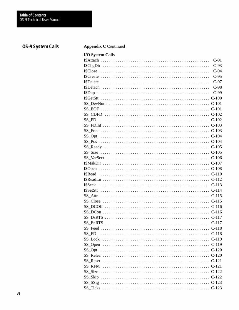
Appendix C Continued
I/O System CallsI$Attach C-91. . . . . . . . . . . . . . . . . . . . . . . . . . . . . . . . . . . . . . . . . . . . . . . . . . . I$ChgDir C-93. . . . . . . . . . . . . . . . . . . . . . . . . . . . . . . . . . . . . . . . . . . . . . . . . . I$Close C-94. . . . . . . . . . . . . . . . . . . . . . . . . . . . . . . . . . . . . . . . . . . . . . . . . . . . I$Create C-95. . . . . . . . . . . . . . . . . . . . . . . . . . . . . . . . . . . . . . . . . . . . . . . . . . . I$Delete C-97. . . . . . . . . . . . . . . . . . . . . . . . . . . . . . . . . . . . . . . . . . . . . . . . . . . I$Detach C-98. . . . . . . . . . . . . . . . . . . . . . . . . . . . . . . . . . . . . . . . . . . . . . . . . . I$Dup C-99. . . . . . . . . . . . . . . . . . . . . . . . . . . . . . . . . . . . . . . . . . . . . . . . . . . . . I$GetStt C-100. . . . . . . . . . . . . . . . . . . . . . . . . . . . . . . . . . . . . . . . . . . . . . . . . . . SS_DevNum C-101. . . . . . . . . . . . . . . . . . . . . . . . . . . . . . . . . . . . . . . . . . . . . . . SS_EOF C-101. . . . . . . . . . . . . . . . . . . . . . . . . . . . . . . . . . . . . . . . . . . . . . . . . . . SS_CDFD C-102. . . . . . . . . . . . . . . . . . . . . . . . . . . . . . . . . . . . . . . . . . . . . . . . . SS_FD C-102. . . . . . . . . . . . . . . . . . . . . . . . . . . . . . . . . . . . . . . . . . . . . . . . . . . . SS_FDInf C-103. . . . . . . . . . . . . . . . . . . . . . . . . . . . . . . . . . . . . . . . . . . . . . . . . . SS_Free C-103. . . . . . . . . . . . . . . . . . . . . . . . . . . . . . . . . . . . . . . . . . . . . . . . . . . SS_Opt C-104. . . . . . . . . . . . . . . . . . . . . . . . . . . . . . . . . . . . . . . . . . . . . . . . . . . . SS_Pos C-104. . . . . . . . . . . . . . . . . . . . . . . . . . . . . . . . . . . . . . . . . . . . . . . . . . . . SS_Ready C-105. . . . . . . . . . . . . . . . . . . . . . . . . . . . . . . . . . . . . . . . . . . . . . . . . SS_Size C-105. . . . . . . . . . . . . . . . . . . . . . . . . . . . . . . . . . . . . . . . . . . . . . . . . . . SS_VarSect C-106. . . . . . . . . . . . . . . . . . . . . . . . . . . . . . . . . . . . . . . . . . . . . . . . I$MakDir C-107. . . . . . . . . . . . . . . . . . . . . . . . . . . . . . . . . . . . . . . . . . . . . . . . . . I$Open C-108. . . . . . . . . . . . . . . . . . . . . . . . . . . . . . . . . . . . . . . . . . . . . . . . . . . . I$Read C-110. . . . . . . . . . . . . . . . . . . . . . . . . . . . . . . . . . . . . . . . . . . . . . . . . . . . I$ReadLn C-112. . . . . . . . . . . . . . . . . . . . . . . . . . . . . . . . . . . . . . . . . . . . . . . . . . I$Seek C-113. . . . . . . . . . . . . . . . . . . . . . . . . . . . . . . . . . . . . . . . . . . . . . . . . . . . I$SetStt C-114. . . . . . . . . . . . . . . . . . . . . . . . . . . . . . . . . . . . . . . . . . . . . . . . . . . SS_Attr C-115. . . . . . . . . . . . . . . . . . . . . . . . . . . . . . . . . . . . . . . . . . . . . . . . . . . SS_Close C-115. . . . . . . . . . . . . . . . . . . . . . . . . . . . . . . . . . . . . . . . . . . . . . . . . . SS_DCOff C-116. . . . . . . . . . . . . . . . . . . . . . . . . . . . . . . . . . . . . . . . . . . . . . . . . SS_DCon C-116. . . . . . . . . . . . . . . . . . . . . . . . . . . . . . . . . . . . . . . . . . . . . . . . . . SS_DsRTS C-117. . . . . . . . . . . . . . . . . . . . . . . . . . . . . . . . . . . . . . . . . . . . . . . . . SS_EnRTS C-117. . . . . . . . . . . . . . . . . . . . . . . . . . . . . . . . . . . . . . . . . . . . . . . . . SS_Feed C-118. . . . . . . . . . . . . . . . . . . . . . . . . . . . . . . . . . . . . . . . . . . . . . . . . . . SS_FD C-118. . . . . . . . . . . . . . . . . . . . . . . . . . . . . . . . . . . . . . . . . . . . . . . . . . . . SS_Lock C-119. . . . . . . . . . . . . . . . . . . . . . . . . . . . . . . . . . . . . . . . . . . . . . . . . . SS_Open C-119. . . . . . . . . . . . . . . . . . . . . . . . . . . . . . . . . . . . . . . . . . . . . . . . . . SS_Opt C-120. . . . . . . . . . . . . . . . . . . . . . . . . . . . . . . . . . . . . . . . . . . . . . . . . . . . SS_Relea C-120. . . . . . . . . . . . . . . . . . . . . . . . . . . . . . . . . . . . . . . . . . . . . . . . . . SS_Reset C-121. . . . . . . . . . . . . . . . . . . . . . . . . . . . . . . . . . . . . . . . . . . . . . . . . . SS_RFM C-121. . . . . . . . . . . . . . . . . . . . . . . . . . . . . . . . . . . . . . . . . . . . . . . . . . SS_Size C-122. . . . . . . . . . . . . . . . . . . . . . . . . . . . . . . . . . . . . . . . . . . . . . . . . . . SS_Skip C-122. . . . . . . . . . . . . . . . . . . . . . . . . . . . . . . . . . . . . . . . . . . . . . . . . . . SS_SSig C-123. . . . . . . . . . . . . . . . . . . . . . . . . . . . . . . . . . . . . . . . . . . . . . . . . . . SS_Ticks C-123. . . . . . . . . . . . . . . . . . . . . . . . . . . . . . . . . . . . . . . . . . . . . . . . . .
OS-9 System Calls

OS-9 Technical User ManualTable of Contents
VII
Appendix C Continued
I/O System Calls ContinuedSS_WFM C-124. . . . . . . . . . . . . . . . . . . . . . . . . . . . . . . . . . . . . . . . . . . . . . . . . . SS_WTrk C-124. . . . . . . . . . . . . . . . . . . . . . . . . . . . . . . . . . . . . . . . . . . . . . . . . . I$Write C-125. . . . . . . . . . . . . . . . . . . . . . . . . . . . . . . . . . . . . . . . . . . . . . . . . . . . I$WritLn C-126. . . . . . . . . . . . . . . . . . . . . . . . . . . . . . . . . . . . . . . . . . . . . . . . . . System-state System CallsF$Alarm C-127. . . . . . . . . . . . . . . . . . . . . . . . . . . . . . . . . . . . . . . . . . . . . . . . . . . A$Delete C-129. . . . . . . . . . . . . . . . . . . . . . . . . . . . . . . . . . . . . . . . . . . . . . . . . . A$Set C-130. . . . . . . . . . . . . . . . . . . . . . . . . . . . . . . . . . . . . . . . . . . . . . . . . . . . . A$Cycle C-131. . . . . . . . . . . . . . . . . . . . . . . . . . . . . . . . . . . . . . . . . . . . . . . . . . . A$AtDate C-132. . . . . . . . . . . . . . . . . . . . . . . . . . . . . . . . . . . . . . . . . . . . . . . . . . A$AtJul C-133. . . . . . . . . . . . . . . . . . . . . . . . . . . . . . . . . . . . . . . . . . . . . . . . . . . F$AllPD C-134. . . . . . . . . . . . . . . . . . . . . . . . . . . . . . . . . . . . . . . . . . . . . . . . . . . F$AllPrc C-135. . . . . . . . . . . . . . . . . . . . . . . . . . . . . . . . . . . . . . . . . . . . . . . . . . F$AProc C-136. . . . . . . . . . . . . . . . . . . . . . . . . . . . . . . . . . . . . . . . . . . . . . . . . . . F$DelPrc C-137. . . . . . . . . . . . . . . . . . . . . . . . . . . . . . . . . . . . . . . . . . . . . . . . . . F$FindPD C-138. . . . . . . . . . . . . . . . . . . . . . . . . . . . . . . . . . . . . . . . . . . . . . . . . F$IOQu C-139. . . . . . . . . . . . . . . . . . . . . . . . . . . . . . . . . . . . . . . . . . . . . . . . . . . F$IRQ C-140. . . . . . . . . . . . . . . . . . . . . . . . . . . . . . . . . . . . . . . . . . . . . . . . . . . . F$Move C-142. . . . . . . . . . . . . . . . . . . . . . . . . . . . . . . . . . . . . . . . . . . . . . . . . . . F$NProc C-143. . . . . . . . . . . . . . . . . . . . . . . . . . . . . . . . . . . . . . . . . . . . . . . . . . . F$Panic C-144. . . . . . . . . . . . . . . . . . . . . . . . . . . . . . . . . . . . . . . . . . . . . . . . . . . F$RetPD C-145. . . . . . . . . . . . . . . . . . . . . . . . . . . . . . . . . . . . . . . . . . . . . . . . . . F$SSvc C-146. . . . . . . . . . . . . . . . . . . . . . . . . . . . . . . . . . . . . . . . . . . . . . . . . . . . F$VModul C-148. . . . . . . . . . . . . . . . . . . . . . . . . . . . . . . . . . . . . . . . . . . . . . . . .
OS-9 System Calls
Chapter
1
1-1
System Overview
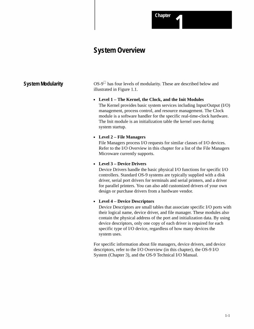
OS-9 has four levels of modularity. These are described below andillustrated in Figure 1.1.
Level 1 – The Kernel, the Clock, and the Init ModulesThe Kernel provides basic system services including Input/Output (I/O)management, process control, and resource management. The Clockmodule is a software handler for the specific real-time-clock hardware.The Init module is an initialization table the kernel uses duringsystem startup.
Level 2 – File ManagersFile Managers process I/O requests for similar classes of I/O devices.Refer to the I/O Overview in this chapter for a list of the File ManagersMicroware currently supports.
Level 3 – Device DriversDevice Drivers handle the basic physical I/O functions for specific I/Ocontrollers. Standard OS-9 systems are typically supplied with a diskdriver, serial port drivers for terminals and serial printers, and a driverfor parallel printers. You can also add customized drivers of your owndesign or purchase drivers from a hardware vendor.
Level 4 – Device DescriptorsDevice Descriptors are small tables that associate specific I/O ports withtheir logical name, device driver, and file manager. These modules alsocontain the physical address of the port and initialization data. By usingdevice descriptors, only one copy of each driver is required for eachspecific type of I/O device, regardless of how many devices thesystem uses.
For specific information about file managers, device drivers, and devicedescriptors, refer to the I/O Overview (in this chapter), the OS-9 I/OSystem (Chapter 3), and the OS-9 Technical I/O Manual.
System Modularity

System OverviewChapter 1
1-2
Figure 1.1OS-9 Module Organization
File Managers
OS–9 KERNEL
Clock
Math Trap HandlersInit
User Applicationsand Utilities
Device Drivers
Device Descriptors
CIO Library
User Trap Handlers
Important: The shaded boxes contain non-executable code. Thesemodules are referenced, not “called.” The kernel, file managers, anddrivers reference descriptors directly, but only the kernel references the Initmodule directly.
An important component, the command interpreter (the Shell), is notshown in the above diagram. The Shell is an application program, not partof the operating system. It is described fully in Using Professional OS-9.To obtain a list of the specific modules that make up OS-9 for your system,use the Ident utility on the OS9Boot file.
Although all modules could be resident in ROM, the system bootstrapmodule is usually the only ROMed module in disk-based systems. Allother modules are loaded into RAM during system startup.

System OverviewChapter 1
1-3
The kernel maintains the I/O system for OS-9. It provides the first level ofI/O service by routing system call requests between processes, and theappropriate file managers and device drivers. Microware includes thefollowing File Managers in the standard professional distribution:
File Manager: Description:
RBF The Random Block File Manager handles I/O for random-access,block-structured devices, such as floppy/hard disk systems.
SCF The Sequential Character File Manager handles I/O for sequentiallycharacter-structured devices, such as terminals, printers, and modems.
SBF The Sequential Block File Manager handles I/O for sequentiallyblock-structured devices, such as tape systems.
PIPEMAN The Pipe File Manager supports interprocess communications throughmemory buffers called pipes.
For specific information about the above file managers, refer to the OS-9I/O System (Chapter 4) or the OS-9 Technical I/O Manual.
Microware also supports the following File Managers which are notincluded in the standard professional distribution:
File Manager: Description:
PCF PC File Manager handles reading/writing PC-DOS disks. It uses RBFdrivers and is sold separately.
NFM Network File Manager processes data requests over the OS-9 network.The OS-9/NFM package includes NFM.
ENPMAN ENP10 Socket File Manager transfers requests to and from CMC ENP10boards. OS-9/ESP, the Ethernet Support Package, includes NPMAN.
SOCKMAN Socket File Manager creates and manages the interface tocommunication protocols (sockets). OS-9/ISP, the Internet SupportPackage, includes SOCKMAN.
IFMAN Communications Interface File Manager manages network interfaces.OS-9/ISP, the Internet Support Package, includes IFMAN.
PKMAN Pseudo-Keyboard File Manager provides an interface to the driver side ofSCF to enable the software to emulate a terminal. OS-9/ESP andOS-9/ISP Packages include PKMAN.
GFM The Graphics File Manager provides a full set of text and graphicsprimitives, input handling for keyboards and pointers, and high levelfeatures for handling user interaction in a real time, multi-taskingenvironment. The OS-9 RAVE package includes the Graphics FileManager.
UCM The User Communications Manager handles video, pointer, and keyboarddevices for CDI (Compact Disc Interactive). The CD-RTOS packageincludes UCM.
CDFM The Compact Disc File Manager handles CD and audio devices, as wellas access to CD ROM and CD audio. The CD-RTOS packageincludes CDFM.
NRF The Non-Volatile RAM File Manager controls non-volatile RAM andhandles a flat (non-hierarchical) directory structure. The CD-RTOSpackage includes NRF.
I/O Overview

System OverviewChapter 1
1-4
Figure 1.2 illustrates how OS-9 processes an I/O request:
Figure 1.2Processing an OS-9 I/O Request
File Manager
OS–9 KERNEL
User Process
Device Driver
The user makes a request for data/status.
The Kernel identifies and validates theI/O request and the identifies theappropriate File Manager, DeviceDriver, and other necessaryresources. Then, the Kernel passesthe request to the appropriate FileManager.
The File Manager validates the request andperforms device-independent processing.The File Manager calls the Device Driverfor hardware interaction, as needed.
The Device Driver performs device-specificprocessing and usually transfers the data/status back to the File Manager.
The File Manager monitors and processesthe data/status and makes requests to theKernel for dynamic memory allocation, asneeded.
The Kernel works with the File Managerto return the data/status to the user.
The user receives the data/status.
Memory Modules
OS-9 is unique in that it uses memory modules to manage both thephysical assignment of memory to programs and the logical contents ofmemory. A memory module is a logical, self-contained program, programsegment, or collection of data.
OS-9 supports ten pre-defined types of modules and allows you to defineyour own module types. Each type of module has a different function.Modules do not have to be complete programs or written in machinelanguage. However, they must be re-entrant, position-independent, andconform to the basic module structure described in the next section.
System OverviewChapter 1
1-5
The 68000 instruction set supports a programming style called re-entrantcode, that is, code that does not modify itself. This allows two or moredifferent processes to share one “copy” of a module simultaneously. Theprocesses do not affect each other, provided that each process has anindependent area for its variables.
Almost all OS-9 family software is re-entrant, and therefore uses memoryvery efficiently. For example, Scred requires 26K bytes of memory to load.If you make a request to run Scred while another user (process) is runningit, OS-9 allows both processes to share the same copy, thus saving 26Kof memory.
Important: Data modules are an exception to the re-entrant requirement.However, careful coordination is required for several processes to update ashared data module simultaneously.
It does not matter where a position-independent module is loaded inmemory. This allows OS-9 to load the program wherever memory space isavailable. In many operating systems, you must specify a load address toplace the program in memory. OS-9 determines an appropriate loadaddress for you when the program is run.
OS-9 compilers and interpreters automatically generateposition-independent code. In assembly language programming, however,the programmer must insure position-independence by avoiding absoluteaddress modes. Alternatives to absolute addressing are described in theOS-9/68000 Assembler/Linker/Debugger User’s Manual.
Basic Module Structure
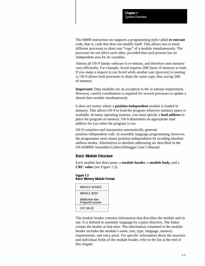
Each module has three parts: a module header, a module body, and aCRC value (see Figure 1.3).
Figure 1.3Basic Memory Module Format
MODULE HEADER
MODULE BODY
Initialization dataProgram/Constants
CRC VALUE
The module header contains information that describes the module and itsuse. It is defined in assembly language by a psect directive. The linkercreates the header at link-time. The information contained in the moduleheader includes the module’s name, size, type, language, memoryrequirements, and entry point. For specific information about the structureand individual fields of the module header, refer to the list at the end ofthis chapter.

System OverviewChapter 1
1-6
The module body contains initialization data, program instructions,constant tables, etc.
The last three bytes of the module hold a CRC value (Cyclic RedundancyCheck value) to verify the module’s integrity. The linker creates the CRCat link-time.
The CRC Value
The CRC (Cyclic Redundancy Check) is an error checking method usedfrequently in data communications and storage systems. It is also a vitalpart of the ROM memory module search technique. A CRC value is at theend of all modules to check the validity of the entire module. It provides anextremely reliable assurance that programs in memory are intact beforeexecution, and is an effective backup for the error detection systems ofdisk drives, memory systems, etc.
OS-9 computes a 24-bit CRC value over the entire module, starting at thefirst byte of the module header and ending at the byte just before the CRCitself. OS-9 family compilers and linkers automatically generate themodule header and CRC values. If required, your program can use theF$CRC system call to compute a CRC value over any specified databytes.Refer to F$CRC in the OS-9 System Calls manual for a full description ofhow F$CRC computes a module’s CRC.
OS-9 does not recognize a module with an incorrect CRC value. Therefore,you must update the CRC value of any “patched” or modified module, orOS-9 cannot load the module from disk or find it in ROM. Use the OS-9Fixmod utility to update the CRC’s of patched modules.
ROMed Memory Modules
When a system reset starts OS-9, the kernel searches for modules in ROM.It detects them by looking for the module header sync code ($4AFC).When the kernel detects this byte pattern, it checks the header parity toverify a correct header. If this test succeeds, the kernel obtains the modulesize from the header and computes a 24-bit CRC over the entire module. Ifthe computed CRC is valid, the module is entered into the moduledirectory.
OS-9 links to all of its component modules found during the search. Itautomatically includes in the system module directory all ROMed modulespresent in the system at startup. This allows you to create systems that arepartially or completely ROM-based. It also includes any non-systemmodules found in ROM. This allows location of user-supplied softwareduring the start-up process, and its entry into the module directory.

System OverviewChapter 1
1-7
Module Header Definitions
The following table and Figure 1.1 list definitions of the standard set offields in the module header.
Name: Description:
M$ID Sync bytes ($4AFC)These constant bytes identify the start of a module.
M$SysRev System revision identificationIdentifies the format of a module.
M$Size Size of moduleThe overall module size in bytes, including header and CRC.
M$Owner Owner IDThe group/user ID of the module’s owner.
M$Name Offset to module nameThe address of the module name string relative to the start (first syncbyte) of the module. The name string can be located anywhere in themodule and consists of a string of ASCII characters terminated by a null(zero) byte.
M$Accs Access permissionsDefines the permissible module access by its owner or other users.Module access permissions are divided into four sections:
reserved (4 bits) public (4 bits) group (4 bits) owner (4 bits)
Each of the non-reserved permission fields is defined as: bit 3 reserved bit 2 execute permission bit 1 write permission bit 0 read permission
The total field is displayed as: -–––––ewr–ewr–ewr
M$Type Module Type CodeModule type values are in the oskdefs.d file. They describe the moduletype code as:
Name: Description:0 Not Used (Wild Card value in system calls)
Prgm 1 Program ModuleSbrtn 2 Subroutine ModuleMulti 3 Multi-Module (reserved for future use)Data 4 Data ModuleCSDData 5 Configuration Status Descriptor
6-10 Reserved for future useTrapLib 11 User Trap LibrarySystm 12 System Module (OS-9 component)Flmgr 13 File Manager ModuleDrivr 14 Physical Device DriverDevic 15 Device Descriptor Module
16-up User Definable

System OverviewChapter 1
1-8
Name: Description:
M$Lang LanguageYou can find module language codes in the oskdefs.d file. They describewhether the module is executable and which language the run-timesystem requires for execution (if any):
Name: Description:0 Unspecified Language (Wild Card value in
system calls) Objct 1 68000 machine language ICode 2 Basic I-code PCode 3 Pascal P-code CCode 4 C I-code (reserved for future use) CblCode 5 Cobol I-code FrtnCode 6 Fortran I-code 7-15 Reserved for future use
16-255 User Definable
NOTE: Not all combinations of module type codes and languagesnecessarily make sense.
M$Attr AttributesBit 5 - Module is a “system state” module.
Bit 6 - Module is a sticky module. A sticky module is retained in memorywhen its link count becomes zero. The module is removed from memorywhen its link count becomes –1 or memory is required for another use.
Bit 7 - Module is re-entrant (sharable by multiple tasks).
M$Revs Revision levelThe module’s revision level. If two modules with the same name and typeare found in the memory search or loaded into memory, only the modulewith the highest revision level is kept. This enables easy substitution ofmodules for update or correction, especially ROMed modules.
M$Edit EditionThe software release level for maintenance. OS-9 does not use this field.Every time a program is revised (even for a small change), increase thisnumber. We recommend that you key internal documentation within thesource program to this system.
M$Usage CommentsReserved for offset to module usage comments (not currently used).
M$Symbol Symbol table offsetReserved for future use.
M$Parity Header parity checkThe one’s complement of the exclusive-OR of the previous header“words.” OS9 uses this for a quick check of the module’s integrity.
Important: Offset refers to the location of a module field, relative to thestarting address of the module. Resolve module offsets in assembly codeby using the names shown here and linking the module with the relocatablelibrary, sys.l or usr.l.
System OverviewChapter 1
1-9
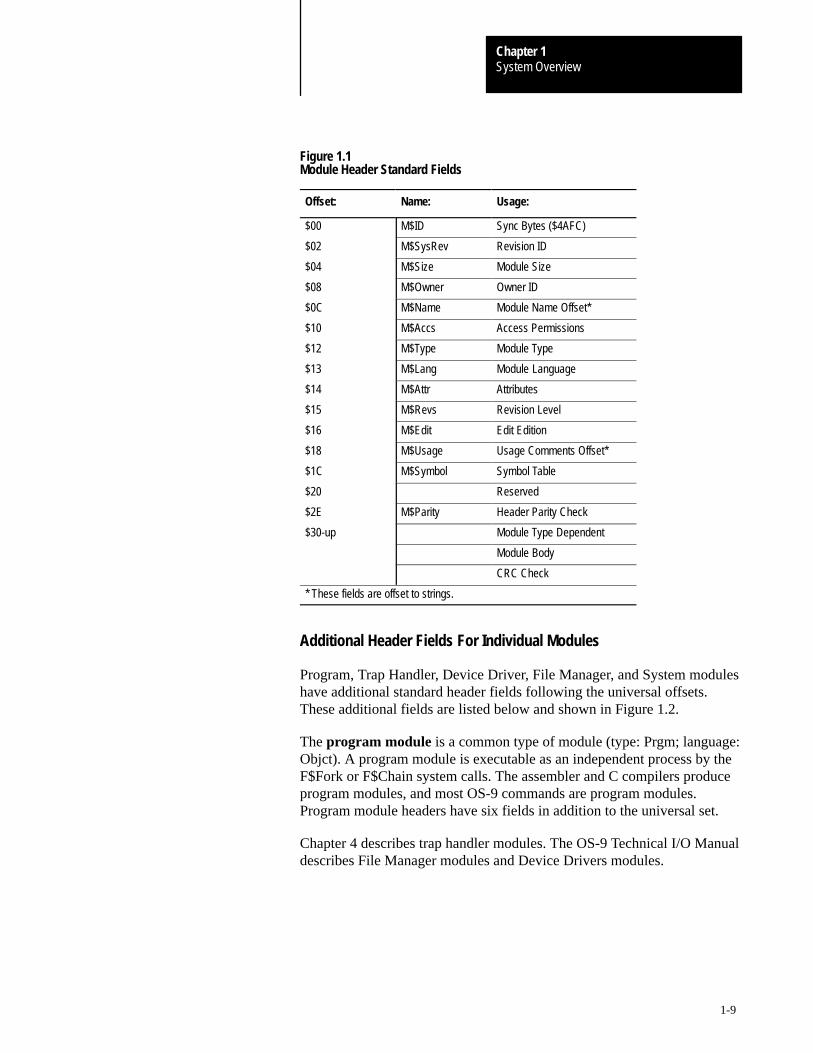
Figure 1.1Module Header Standard Fields
Offset: Name: Usage:
$00 M$ID Sync Bytes ($4AFC)
$02 M$SysRev Revision ID
$04 M$Size Module Size
$08 M$Owner Owner ID
$0C M$Name Module Name Offset*
$10 M$Accs Access Permissions
$12 M$Type Module Type
$13 M$Lang Module Language
$14 M$Attr Attributes
$15 M$Revs Revision Level
$16 M$Edit Edit Edition
$18 M$Usage Usage Comments Offset*
$1C M$Symbol Symbol Table
$20 Reserved
$2E M$Parity Header Parity Check
$30-up Module Type Dependent
Module Body
CRC Check
* These fields are offset to strings.
Additional Header Fields For Individual Modules
Program, Trap Handler, Device Driver, File Manager, and System moduleshave additional standard header fields following the universal offsets.These additional fields are listed below and shown in Figure 1.2.
The program module is a common type of module (type: Prgm; language:Objct). A program module is executable as an independent process by theF$Fork or F$Chain system calls. The assembler and C compilers produceprogram modules, and most OS-9 commands are program modules.Program module headers have six fields in addition to the universal set.
Chapter 4 describes trap handler modules. The OS-9 Technical I/O Manualdescribes File Manager modules and Device Drivers modules.
System OverviewChapter 1
1-10
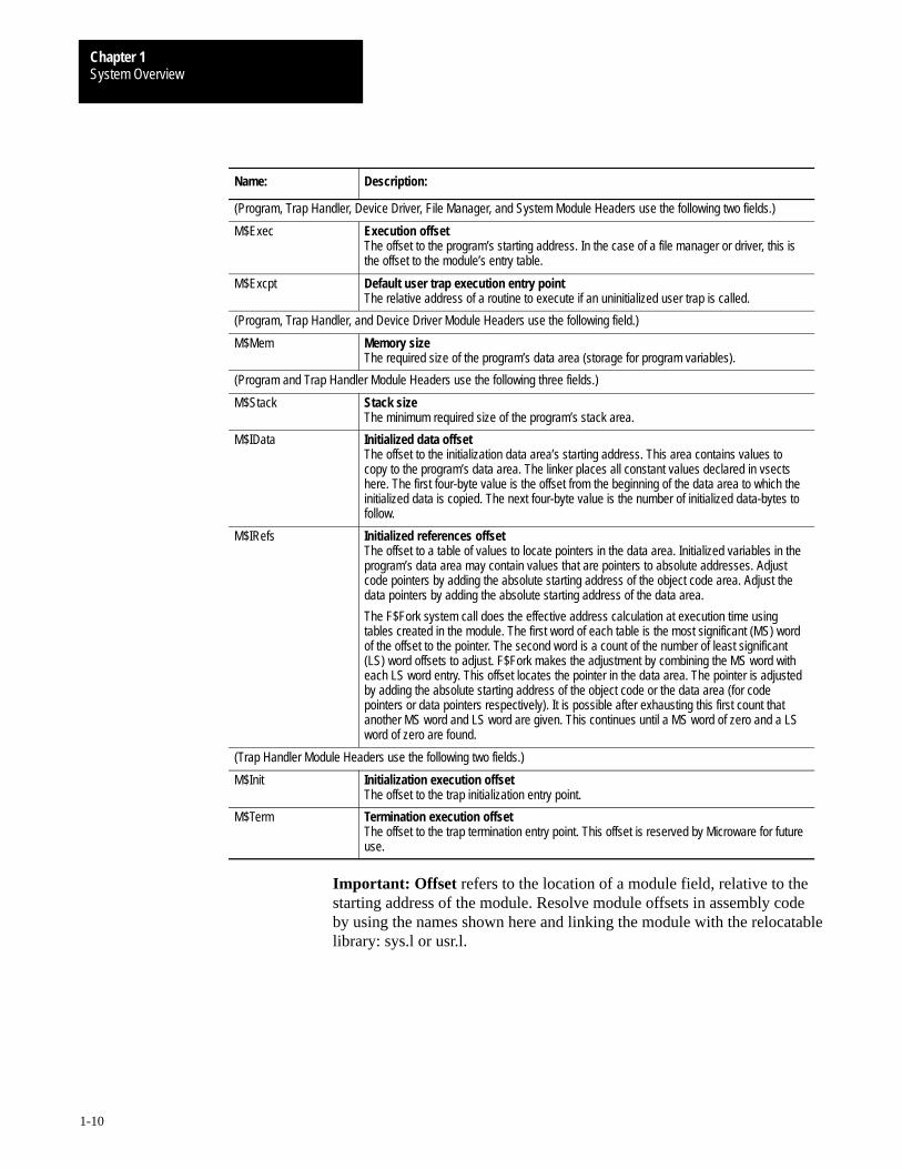
Name: Description:
(Program, Trap Handler, Device Driver, File Manager, and System Module Headers use the following two fields.)
M$Exec Execution offsetThe offset to the program’s starting address. In the case of a file manager or driver, this isthe offset to the module’s entry table.
M$Excpt Default user trap execution entry pointThe relative address of a routine to execute if an uninitialized user trap is called.
(Program, Trap Handler, and Device Driver Module Headers use the following field.)
M$Mem Memory sizeThe required size of the program’s data area (storage for program variables).
(Program and Trap Handler Module Headers use the following three fields.)
M$Stack Stack sizeThe minimum required size of the program’s stack area.
M$IData Initialized data offsetThe offset to the initialization data area’s starting address. This area contains values tocopy to the program’s data area. The linker places all constant values declared in vsectshere. The first four-byte value is the offset from the beginning of the data area to which theinitialized data is copied. The next four-byte value is the number of initialized data-bytes tofollow.
M$IRefs Initialized references offsetThe offset to a table of values to locate pointers in the data area. Initialized variables in theprogram’s data area may contain values that are pointers to absolute addresses. Adjustcode pointers by adding the absolute starting address of the object code area. Adjust thedata pointers by adding the absolute starting address of the data area.
The F$Fork system call does the effective address calculation at execution time usingtables created in the module. The first word of each table is the most significant (MS) wordof the offset to the pointer. The second word is a count of the number of least significant(LS) word offsets to adjust. F$Fork makes the adjustment by combining the MS word witheach LS word entry. This offset locates the pointer in the data area. The pointer is adjustedby adding the absolute starting address of the object code or the data area (for codepointers or data pointers respectively). It is possible after exhausting this first count thatanother MS word and LS word are given. This continues until a MS word of zero and a LSword of zero are found.
(Trap Handler Module Headers use the following two fields.)
M$Init Initialization execution offsetThe offset to the trap initialization entry point.
M$Term Termination execution offsetThe offset to the trap termination entry point. This offset is reserved by Microware for futureuse.
Important: Offset refers to the location of a module field, relative to thestarting address of the module. Resolve module offsets in assembly codeby using the names shown here and linking the module with the relocatablelibrary: sys.l or usr.l.
System OverviewChapter 1
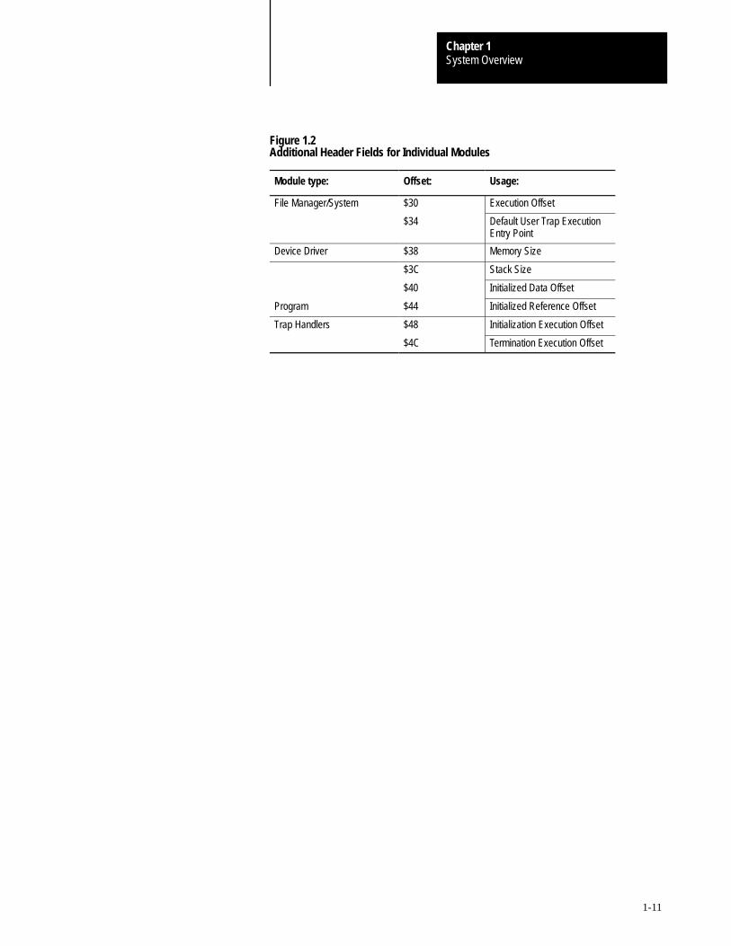
1-11
Figure 1.2Additional Header Fields for Individual Modules
Module type: Offset: Usage:
File Manager/System $30 Execution Offset
$34 Default User Trap ExecutionEntry Point
Device Driver $38 Memory Size
$3C Stack Size
$40 Initialized Data Offset
Program $44 Initialized Reference Offset
Trap Handlers $48 Initialization Execution Offset
$4C Termination Execution Offset
Chapter
2
2-1
The Kernel
The kernel is the nucleus of OS-9. It manages resources, controlsprocessing, and supervises Input/Output. It is a ROMable, compactOS-9 module.
The kernel’s primary responsibility is to process and coordinate systemcalls, or service requests. OS-9 has two general types of system calls:
calls that perform Input/Output, such as reads and writes
calls that perform system functions. System functions include memorymanagement, system initialization, process creation and scheduling, andexception/interrupt processing
When a system call is made, a user trap to the kernel occurs. The kerneldetermines what type of system call the user wants to perform. It directlyexecutes the calls that perform system functions, but does not execute I/Ocalls. The kernel provides the first level of processing for each I/O call,then completes the function as required by calling the appropriate filemanager or driver.
For information on specific system calls, refer to the OS-9 System Callssection of this manual.
For specific information about creating new file managers, and exampleswhich you can adapt to your specific system needs, refer to the OS-9Technical I/O Manual.
For information about specific system calls, refer to OS-9 System Calls.
Responsibilities of theKernel
System Call Overview
The KernelChapter 2
2-2
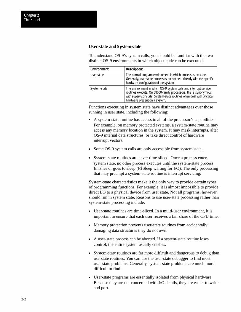
User-state and System-state
To understand OS-9’s system calls, you should be familiar with the twodistinct OS-9 environments in which object code can be executed:
Environment: Description:
User-state The normal program environment in which processes execute.Generally, user-state processes do not deal directly with the specifichardware configuration of the system.
System-state The environment in which OS-9 system calls and interrupt serviceroutines execute. On 68000-family processors, this is synonymouswith supervisor state. System-state routines often deal with physicalhardware present on a system.
Functions executing in system state have distinct advantages over thoserunning in user state, including the following:
A system-state routine has access to all of the processor’s capabilities.For example, on memory protected systems, a system-state routine mayaccess any memory location in the system. It may mask interrupts, alterOS-9 internal data structures, or take direct control of hardwareinterrupt vectors.
Some OS-9 system calls are only accessible from system state.
System-state routines are never time-sliced. Once a process enterssystem state, no other process executes until the system-state processfinishes or goes to sleep (F$Sleep waiting for I/O). The only processingthat may preempt a system-state routine is interrupt servicing.
System-state characteristics make it the only way to provide certain typesof programming functions. For example, it is almost impossible to providedirect I/O to a physical device from user state. Not all programs, however,should run in system state. Reasons to use user-state processing rather thansystem-state processing include:
User-state routines are time-sliced. In a multi-user environment, it isimportant to ensure that each user receives a fair share of the CPU time.
Memory protection prevents user-state routines from accidentallydamaging data structures they do not own.
A user-state process can be aborted. If a system-state routine losescontrol, the entire system usually crashes.
System-state routines are far more difficult and dangerous to debug thanuserstate routines. You can use the user-state debugger to find mostuser-state problems. Generally, system-state problems are much moredifficult to find.
User-state programs are essentially isolated from physical hardware.Because they are not concerned with I/O details, they are easier to writeand port.
The KernelChapter 2
2-3
Installing System-state Routines
System-state routines have direct access to all system hardware, and havethe power to take over the entire machine, crashing or hanging up thesystem. To help prevent this, OS9 limits the methods of creating routinesthat operate in system state.
There are four ways to provide system-state routines:
Install an OS9P2 module in the system bootstrap file or in ROM. Duringcold start, the OS-9 kernel links to this module, and if found, calls itsexecution entry point. The most likely thing for such a module to do isinstall new system call codes. The drawback to this method is that theOS9P2 module must be in ROM or in the bootfile when the systemis bootstrapped.
Use the I/O system as an entry into system state. File managers anddevice drivers always execute in system state. The most obvious reasonto write systemstate routines is to provide support for new hardwaredevices. It is possible to write a dummy device driver and use theI$GetStt or I$SetStt routines to provide a gateway to the driver.
Write a trap handler module that executes in system state. For routinesof limited use that are dynamically loaded and unlinked, this may be themost convenient method. In many cases, it is practical to debug most ofthe trap handler routines in user state, then convert the trap module tosystem state. To make a trap handler execute in system state, you mustset the supervisor state bit in the module attribute byte and create themodule as super user. When the user trap executes, it is in system state.
A program executes in system state if the supervisor state bit in themodule’s attribute word is set and the module is owned by the superuser. This can be useful in rare instances.
Important: System-state routines are not time-sliced, therefore theyshould be as short and fast as possible.
Kernel System Call Processing
All OS-9 system calls (service requests) are processed through the kernel.The system-wide relocatable library files, sys.l and usr.l, define symbolicnames for all system calls. The files are linked with hand-written assemblylanguage or compiler-generated code. The OS-9 Assembler has a built-inmacro to generate system calls:
OS9 I$Read
The KernelChapter 2
2-4
This is recognized and assembled to produce the same code as:
TRAP #0
dc.w I$Read
In addition, the C Compiler standard library includes functions to accessnearly all user mode OS-9 system calls from C programs.
Parameters for system calls are usually passed and returned in registers.There are two general types of system calls: system function calls (callsthat do not perform I/O) and I/O calls.
System Function CallsThere are two types of system function calls, user-state and system-state:
Type: Description:
User-state System Calls These requests perform memory management, multi-tasking, andother functions for user programs. They are mainly processed bythe kernel.
System-state System Calls Only system software in system state can use these calls, andthey usually operate on internal OS-9 data structures. Topreserve OS-9’s modularity, these requests are system callsrather than subroutines. User-state programs cannot accessthem, but system modules such as device drivers may use them.
The symbolic name of each system function call begins with F$. Forexample, the system call to link a module is F$Link.
In general, system-state routines may use any of the user-state system calls.However, you must avoid making system calls at inappropriate times. Forexample, avoid I/O calls, timed sleep requests, and other calls that can beparticularly time consuming (such as F$CRC) in an interruptservice routine.
Memory requested in system state is not recorded in the process descriptormemory list. Therefore, you must ensure that the memory is returned to thesystem before the process terminates.
ATTENTION: Avoid the F$TLink and F$Icpt system calls insystem-state routines. Certain portions of the C library may beinappropriate for use in system state.

The KernelChapter 2
2-5
I/O CallsI/O calls perform various I/O functions. The file manager, device driver,and kernel process I/O calls for a particular device. The symbolic namesfor this category of calls begin with I$. For example, the read servicerequest is I$Read.
You may use any I/O system call in a system-state routine, with one slightdifference than when executed in user-state. All path numbers used insystem state are system path numbers. Each process descriptor has a pathnumber that converts process local path numbers into system pathnumbers. The system itself has a global path number table to convertsystem path numbers into actual addresses of path descriptors. You mustmake system-state I/O system calls using system path numbers.
For example, the OS-9 F$PErr system call prints an error message on thecaller’s standard error path. To do this, it may not simply perform outputon path number two. Instead it must examine the caller’s process descriptorand extract the system path number from the third entry (0, 1, 2, ...) in thecaller’s path table.
When a user-state process exits with I/O paths open, the F$Exit routineautomatically closes the paths. This is possible because OS-9 keeps trackof the open paths in the process’s path table. In system state, the I$Openand I$Create system calls return a system path number which is notrecorded in the process path table or anywhere else by OS-9. Therefore,the system-state routine that opens any I/O paths must ensure that the pathsare eventually closed, even if the underlying process is abnormallyterminated.
To load any object (such as a program or constant table) into memory, theobject must have the standard OS-9 memory module format as described inChapter 1. This enables OS-9 to maintain a module directory to keeptrack of modules in memory. The module directory contains the name,address, and other related information about each module in memory.
OS-9 adds the module to the module directory when it is loaded intomemory. Each directory entry contains a link count. The link count is thenumber of processes using the module.
When a process links to a module in memory, the module’s link countincrements by one. When a process unlinks from a module, the module’slink count decrements by one. When a module’s link count becomes zero,its memory is de-allocated and it is removed from the module directory,unless the module is sticky.
A sticky module is not removed from memory until its link count becomes–1 or memory is required for another use. A module is sticky if the sixthbit of the module header’s attribute field (M$Attr) is set.
Memory Management
The KernelChapter 2
2-6
OS-9 Memory Map
OS-9 uses a software memory management system that contains allmemory within a single memory map. Therefore, all user tasks share acommon address space.
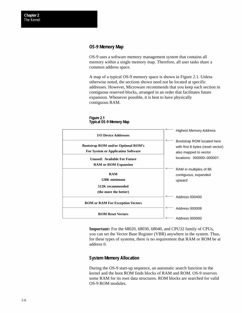
A map of a typical OS-9 memory space is shown in Figure 2.1. Unlessotherwise noted, the sections shown need not be located at specificaddresses. However, Microware recommends that you keep each section incontiguous reserved blocks, arranged in an order that facilitates futureexpansion. Whenever possible, it is best to have physicallycontiguous RAM.
Figure 2.1Typical OS-9 Memory Map
Bootstrap ROM and/or Optional ROM’s
For System or Application Software
I/O Device Addresses
Unused: Available For Future
RAM or ROM Expansion
RAM
128K minimum
512K recommended
(the more the better)
ROM or RAM For Exception Vectors
ROM Reset Vectors
Highest Memory Address
Bootstrap ROM located here
with first 8 bytes (reset vector)
also mapped to vector
locations: 000000–000007.
RAM in multiples of 8K
contiguous, expanded
Address 000400
Address 000008
Address 000000
upward
Important: For the 68020, 68030, 68040, and CPU32 family of CPUs,you can set the Vector Base Register (VBR) anywhere in the system. Thus,for these types of systems, there is no requirement that RAM or ROM be ataddress 0.
System Memory Allocation
During the OS-9 start-up sequence, an automatic search function in thekernel and the boot ROM finds blocks of RAM and ROM. OS-9 reservessome RAM for its own data structures. ROM blocks are searched for validOS-9 ROM modules.

The KernelChapter 2
2-7
OS-9 requires a variable amount of memory. Actual requirements dependon the system configuration and the number of active tasks and open files.The following sections describe approximate amounts of memory used byvarious parts of OS-9.
Operating System Object CodeA complete set of typical operating system component modules (kernel,file managers, device drivers, device descriptors, tick driver) occupiesabout 50K to 64K bytes of memory. On disk-based systems, these modulesare normally bootstrap-loaded into RAM. OS-9 does not dynamically loadoverlays or swap system code; therefore, no additional RAM is requiredfor system code.
You can place OS-9 in ROM for non-disk systems. The typical operatingsystem object code for ROM-based, non-disk systems occupies about 30Kto 40K bytes.
System Global MemoryOS-9 uses a minimum of 8K RAM for internal use. The system globalmemory area is usually located at the lowest RAM addressed. It containsan exception jump table, the debugger/boot variables, and a system globalarea. Variables in the system global area are symbolically defined in thesys.l library and the variable names begin with D_. The Reset SSP vectorpoints to the system global area.
ATTENTION: User programs should never directly accesssystem global variables because of issues such as portability and(depending on hardware) memory protection. System calls areprovided to allow user programs to read the information inthis area.
System Dynamic MemoryOS-9 maintains dynamic-sized data structures (such as I/O buffers, pathdescriptors, process descriptors, etc.) which are allocated from the generalRAM area when needed. The System Global Memory area keeps pointersto the addresses of these data structures. A typical small system usesapproximately 16K of RAM. The total depends on elements such as thenumber of active devices, the memory, and the number of active processes.The sys.l library source files include the exact sizes of all the system’s datastructure elements.
The KernelChapter 2
2-8
Free Memory PoolAll unused RAM memory is assigned to a free memory pool. Memoryspace is removed and returned to the pool as it is allocated or de-allocatedfor various purposes. OS-9 automatically assigns memory from the freememory pool whenever any of the following occur:
Modules are loaded into RAM.
New processes are created.
Processes request additional RAM.
OS-9 requires more I/O buffers or its internal data structures mustbe expanded.
Storage for user program object code modules and data space isdynamically allocated from and de-allocated to the free memory pool. Userobject code modules are automatically shared if two or more tasks executethe same object program. User object code application programs can alsobe stored in ROM memory.
The total memory required for user memory depends largely on theapplication software to be run. Microware suggests that you have a systemminimum of 128K plus an additional 64K per user available. Alternatively,small ROM-based control system might only need 32K of memory.
Memory Fragmentation
Once a program is loaded, it must remain at the address where it wasoriginally loaded. Although position-independent programs can be initiallyplaced at any address where free memory is available, program modulescannot be relocated dynamically after they are loaded. This can lead tomemory fragmentation.
When programs are loaded, they are assigned the first sufficiently largeblock of memory at the highest address possible in the address space. (If acolored memory request is made, this may not be true. Refer to thefollowing section for more information on colored memory.) If a numberof program modules are loaded, and subsequently one or morenon-contiguous modules are unlinked, several fragments of free memoryspace exist. The total free memory space may be quite large. However,because it is scattered, not enough space will exist in a single block to loada particular program module.
You can avoid memory fragmentation by loading modules at systemstartup. This places the modules in contiguous memory space. Or, you caninitialize each standard device when booting the system. This allows thedevices to allocate memory from higher RAM than would be available ifthe devices were initialized after booting.

The KernelChapter 2
2-9
If serious memory fragmentation does occur, the system administrator cankill processes and unlink modules in ascending order of importance untilthere is sufficient contiguous memory to proceed. Use the mfree utility todetermine the number and size of free memory blocks.
Colored Memory
OS-9 colored memory allows a system to recognize different memorytypes and reserve areas for special purposes. For example, you coulddesign a part of a system’s RAM to store video images and battery back upanother part. The kernel allows isolation and specific access of areas ofRAM like these. You can request specific memory types or “colors” whenallocating memory buffers, creating modules in memory, or loadingmodules into memory. If a specific type of memory is not available, thekernel returns error #237, E$NoRAM.
Colored memory lists are not essential on systems with RAM consisting ofone homogeneous type, although they can improve system performance onsome systems and allow greater flexibility in configuring memory searchareas. The default memory allocation requests are still appropriate for mosthomogeneous systems and for applications which do not require onememory type over another. Colored memory lists are required for theF$Trans system call to perform address translation.
Colored Memory Definition ListThe kernel must have a description of the CPU’s address space to make useof the colored memory routines. You can establish colored memory byincluding a colored memory definition list (MemList) in the systype.d file,which then becomes part of the Init module. The list describes eachmemory region’s characteristics. The kernel searches each region in the listfor RAM during system startup.
A colored memory definition list contains the following information:
memory color (type)
memory priority
memory access permissions
local bus address
block size the kernel’s coldstart routine uses to search the area for RAMor ROM
external bus translation address (for DMA, dual-ported RAM, etc.)
optional name

The KernelChapter 2
2-10
The memory list may contain as many regions as needed. If no list isspecified, the kernel automatically creates one region that describes thememory found by the bootstrap ROM.
MemList is a series of MemType macros defined in systype.d and used byinit.a. Each line in the MemList must contain all the following parameters,in order:
type, priority, attributes, blksiz, addr begin, addr end, name, DMA-offset
The colored memory list must end with a longword of zero. The followingdescribes the MemList parameters:
Parameter: Size: Size:
Memory Type word Type of memory. Three memory types are currently defined inmemory.h:
SYSRAM 0x01 System RAM memoryVIDEO1 0x80 Video memory for plane AVIDEO2 0x81 Video memory for plane B
Priority word Priority of memory (0-255). High priority memory is allocatedfirst. If the block priority is 0, then the block can only beallocated by a request for the specific color (type) of the block.
Access permissions word Memory type access bit definitions:
bit 0 B_USER User processes can allocate this memory.
NOTE: This bit is ignored if the B_ROM bitis set.
bit 1 B_PARITY Parity memory; the kernel initializes thismemory during startup.
NOTE: Only B_USER memory may beinitialized.
bit 2 B_ROM ROM; the kernel searches this memory formodules during startup.
NOTE: B_ROM memory cannot beallocated by processes, as the B_USERand B_PARITY bits are ignored if B_ROMis set.
Search Block Size word The kernel checks every search block size to see ifRAM/ROM exists.
Low Memory Limit long Beginning address of the block, as referenced by the CPU.
High Memory Limit long End address of the block, as referenced by the CPU.
Description String Offset word Offset of a user-defined string that describes the type ofmemory block.
Address TranslationAdjustment
long The external bus address of the beginning of the block. If zero,this field does not apply. Refer to F$Trans for more information.
The KernelChapter 2
2-11
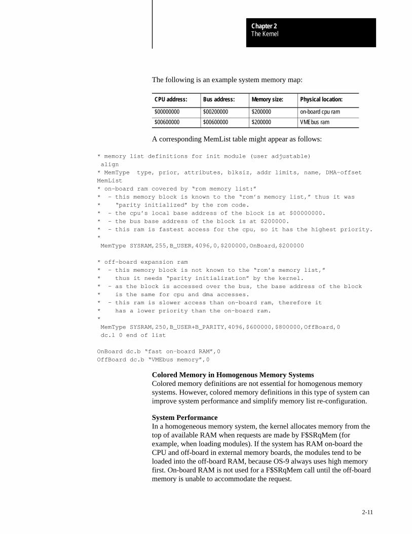
The following is an example system memory map:
CPU address: Bus address: Memory size: Physical location:
$00000000 $00200000 $200000 on-board cpu ram
$00600000 $00600000 $200000 VMEbus ram
A corresponding MemList table might appear as follows:
* memory list definitions for init module (user adjustable)
align
* MemType type, prior, attributes, blksiz, addr limits, name, DMA–offset
MemList
* on–board ram covered by “rom memory list:”
* – this memory block is known to the “rom’s memory list,” thus it was
* “parity initialized” by the rom code.
* – the cpu’s local base address of the block is at $00000000.
* – the bus base address of the block is at $200000.
* – this ram is fastest access for the cpu, so it has the highest priority.
*
MemType SYSRAM,255,B_USER,4096,0,$200000,OnBoard,$200000
* off–board expansion ram
* – this memory block is not known to the “rom’s memory list,”
* thus it needs “parity initialization” by the kernel.
* – as the block is accessed over the bus, the base address of the block
* is the same for cpu and dma accesses.
* – this ram is slower access than on–board ram, therefore it
* has a lower priority than the on–board ram.
*
MemType SYSRAM,250,B_USER+B_PARITY,4096,$600000,$800000,OffBoard,0
dc.l 0 end of list
OnBoard dc.b “fast on–board RAM”,0
OffBoard dc.b “VMEbus memory”,0
Colored Memory in Homogenous Memory SystemsColored memory definitions are not essential for homogenous memorysystems. However, colored memory definitions in this type of system canimprove system performance and simplify memory list re-configuration.
System PerformanceIn a homogeneous memory system, the kernel allocates memory from thetop of available RAM when requests are made by F$SRqMem (forexample, when loading modules). If the system has RAM on-board theCPU and off-board in external memory boards, the modules tend to beloaded into the off-board RAM, because OS-9 always uses high memoryfirst. On-board RAM is not used for a F$SRqMem call until the off-boardmemory is unable to accommodate the request.

The KernelChapter 2
2-12
Programs running in off-board memory execute slower than those runningin on-board memory, due to bus access arbitration. Also, external busactivity increases. This may impact the performance of other bus mastersin the system.
The colored memory lists can be used to reverse this tendency in thekernel, so that a CPU does not use off-board memory until all of itson-board memory is utilized. This results in faster program execution andless saturation of the system’s external bus. Do this by making the priorityof the on-board memory higher than off-board memory, as shown in theexample lists on the preceding page.
Re-configuring Memory AreasIn a homogeneous memory system, the memory search areas are defined inthe ROM’s Memory List. If you do not use colored memory, you mustmake new ROMs from source code (usually impossible for end-users) orfrom a patched version of the original ROMs (usually difficult forend-users) to make changes to the memory search areas.
The colored memory lists simplify changes by configuring the search areasas follows:
The ROM’s memory list describes only the on-board memory.
The colored memory lists in systype.d define the on-board memory andany external bus memory search areas in the Init module only.
The use of colored memory in a homogeneous memory system allows youto easily reconfigure the external bus search areas by adjusting the lists insystype.d and making a new Init module. The ROM does notrequire patching.
After a hardware reset, the bootstrap ROM executes the kernel (which islocated in ROM or loaded from disk, depending on the system involved).The kernel initializes the system, which includes locating ROM modulesand running the system startup task (usually Sysgo).
Init: The Configuration Module
Init is a non-executable module of type Systm (code $0C) which containsa table of system startup parameters. During startup, Init specifies initialtable sizes and system device names, but it is always available to determinesystem limits. It must be in memory when the kernel executes and usuallyresides in the OS9Boot file or in ROM.
System Initialization
The KernelChapter 2
2-13
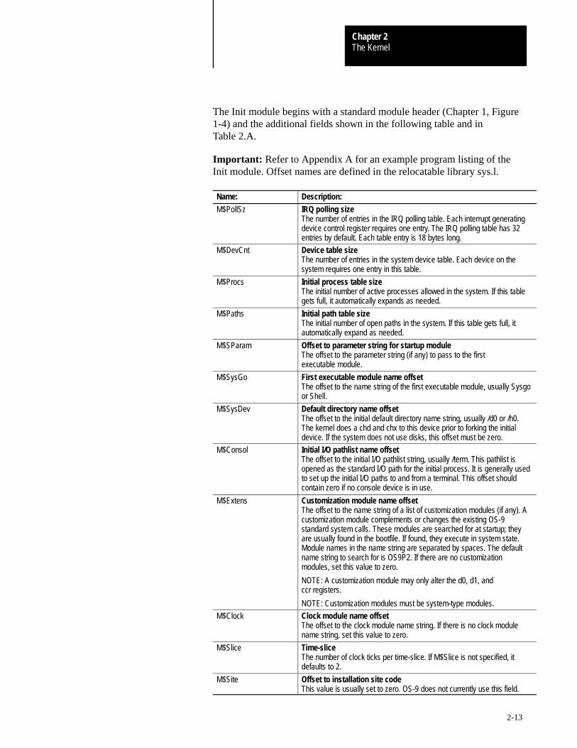
The Init module begins with a standard module header (Chapter 1, Figure1-4) and the additional fields shown in the following table and inTable 2.A.
Important: Refer to Appendix A for an example program listing of theInit module. Offset names are defined in the relocatable library sys.l.
Name: Description:
M$PollSz IRQ polling sizeThe number of entries in the IRQ polling table. Each interrupt generatingdevice control register requires one entry. The IRQ polling table has 32entries by default. Each table entry is 18 bytes long.
M$DevCnt Device table sizeThe number of entries in the system device table. Each device on thesystem requires one entry in this table.
M$Procs Initial process table sizeThe initial number of active processes allowed in the system. If this tablegets full, it automatically expands as needed.
M$Paths Initial path table sizeThe initial number of open paths in the system. If this table gets full, itautomatically expand as needed.
M$SParam Offset to parameter string for startup moduleThe offset to the parameter string (if any) to pass to the firstexecutable module.
M$SysGo First executable module name offsetThe offset to the name string of the first executable module, usually Sysgoor Shell.
M$SysDev Default directory name offsetThe offset to the initial default directory name string, usually /d0 or /h0.The kernel does a chd and chx to this device prior to forking the initialdevice. If the system does not use disks, this offset must be zero.
M$Consol Initial I/O pathlist name offsetThe offset to the initial I/O pathlist string, usually /term. This pathlist isopened as the standard I/O path for the initial process. It is generally usedto set up the initial I/O paths to and from a terminal. This offset shouldcontain zero if no console device is in use.
M$Extens Customization module name offsetThe offset to the name string of a list of customization modules (if any). Acustomization module complements or changes the existing OS-9standard system calls. These modules are searched for at startup; theyare usually found in the bootfile. If found, they execute in system state.Module names in the name string are separated by spaces. The defaultname string to search for is OS9P2. If there are no customizationmodules, set this value to zero.
NOTE: A customization module may only alter the d0, d1, andccr registers.
NOTE: Customization modules must be system-type modules.
M$Clock Clock module name offsetThe offset to the clock module name string. If there is no clock modulename string, set this value to zero.
M$Slice Time-sliceThe number of clock ticks per time-slice. If M$Slice is not specified, itdefaults to 2.
M$Site Offset to installation site codeThis value is usually set to zero. OS-9 does not currently use this field.
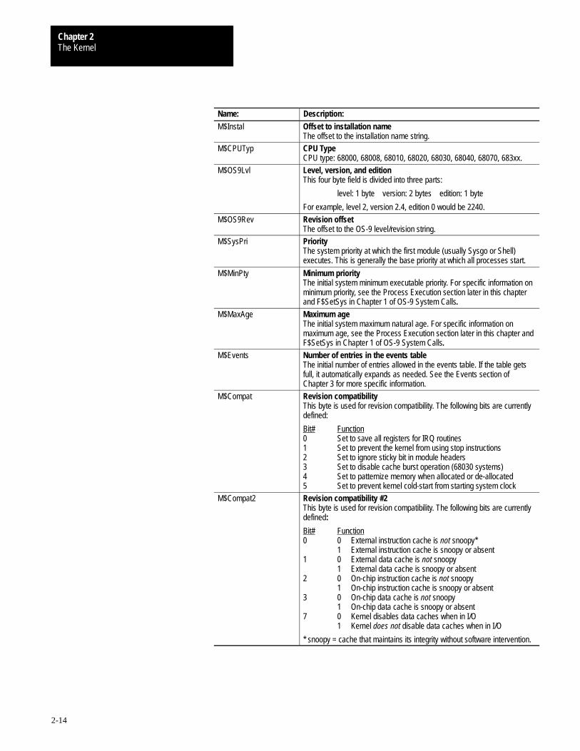
The KernelChapter 2
2-14
Name: Description:
M$Instal Offset to installation nameThe offset to the installation name string.
M$CPUTyp CPU TypeCPU type: 68000, 68008, 68010, 68020, 68030, 68040, 68070, 683xx.
M$OS9Lvl Level, version, and editionThis four byte field is divided into three parts:
level: 1 byte version: 2 bytes edition: 1 byte
For example, level 2, version 2.4, edition 0 would be 2240.
M$OS9Rev Revision offsetThe offset to the OS-9 level/revision string.
M$SysPri PriorityThe system priority at which the first module (usually Sysgo or Shell)executes. This is generally the base priority at which all processes start.
M$MinPty Minimum priorityThe initial system minimum executable priority. For specific information onminimum priority, see the Process Execution section later in this chapterand F$SetSys in Chapter 1 of OS-9 System Calls.
M$MaxAge Maximum ageThe initial system maximum natural age. For specific information onmaximum age, see the Process Execution section later in this chapter andF$SetSys in Chapter 1 of OS-9 System Calls.
M$Events Number of entries in the events tableThe initial number of entries allowed in the events table. If the table getsfull, it automatically expands as needed. See the Events section ofChapter 3 for more specific information.
M$Compat Revision compatibilityThis byte is used for revision compatibility. The following bits are currentlydefined:
Bit# Function0 Set to save all registers for IRQ routines 1 Set to prevent the kernel from using stop instructions2 Set to ignore sticky bit in module headers 3 Set to disable cache burst operation (68030 systems)4 Set to patternize memory when allocated or de-allocated5 Set to prevent kernel cold-start from starting system clock
M$Compat2 Revision compatibility #2This byte is used for revision compatibility. The following bits are currentlydefined:
Bit# Function0 0 External instruction cache is not snoopy*
1 External instruction cache is snoopy or absent1 0 External data cache is not snoopy
1 External data cache is snoopy or absent2 0 On-chip instruction cache is not snoopy
1 On-chip instruction cache is snoopy or absent3 0 On-chip data cache is not snoopy
1 On-chip data cache is snoopy or absent7 0 Kernel disables data caches when in I/O
1 Kernel does not disable data caches when in I/O
* snoopy = cache that maintains its integrity without software intervention.
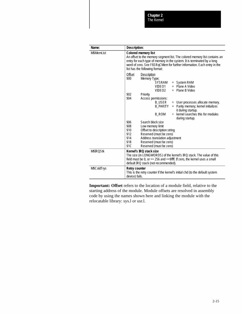
The KernelChapter 2
2-15
Name: Description:
M$MemList Colored memory listAn offset to the memory segment list. The colored memory list contains anentry for each type of memory in the system. It is terminated by a longword of zero. See F$SRqCMem for further information. Each entry in thelist has the following format:
Offset Description$00 Memory Type;
SYSRAM = System RAMVIDEO1 = Plane A VideoVIDEO2 = Plane B Video
$02 Priority$04 Access permissions:
B_USER = User processes allocate memory.B_PARITY = Parity memory; kernel initializes
it during startup.B_ROM = kernel searches this for modules
during startup.$06 Search block size$08 Low memory limit$10 Offset to description string$12 Reserved (must be zero)$14 Address translation adjustment$18 Reserved (must be zero)$1C Reserved (must be zero)
M$IRQStk Kernel’s IRQ stack sizeThe size (in LONGWORDS) of the kernel’s IRQ stack. The value of thisfield must be 0, or >= 256 and <=$ffff. If zero, the kernel uses a smalldefault IRQ stack (not recommended).
M$ColdTrys Retry counterThis is the retry counter if the kernel’s initial chd (to the default systemdevice) fails.
Important: Offset refers to the location of a module field, relative to thestarting address of the module. Module offsets are resolved in assemblycode by using the names shown here and linking the module with therelocatable library: sys.l or usr.l.
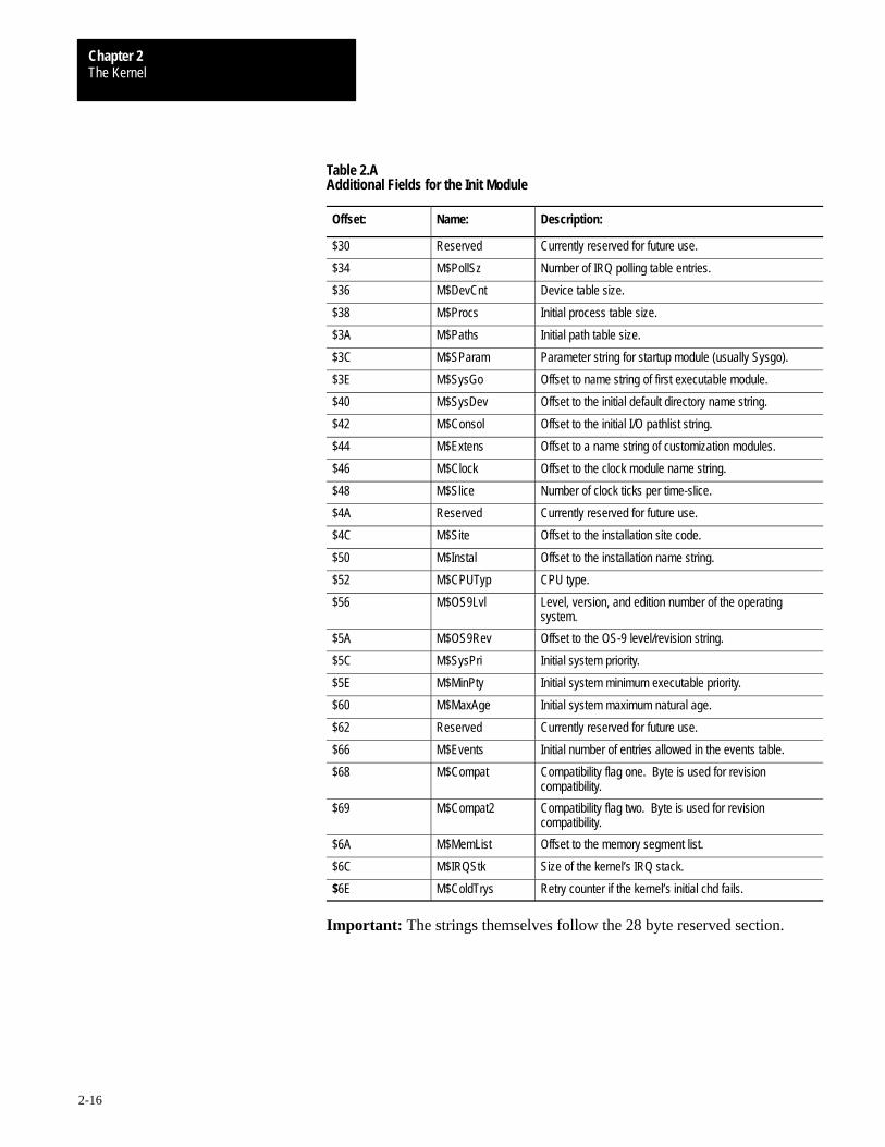
The KernelChapter 2
2-16
Table 2.AAdditional Fields for the Init Module
Offset: Name: Description:
$30 Reserved Currently reserved for future use.
$34 M$PollSz Number of IRQ polling table entries.
$36 M$DevCnt Device table size.
$38 M$Procs Initial process table size.
$3A M$Paths Initial path table size.
$3C M$SParam Parameter string for startup module (usually Sysgo).
$3E M$SysGo Offset to name string of first executable module.
$40 M$SysDev Offset to the initial default directory name string.
$42 M$Consol Offset to the initial I/O pathlist string.
$44 M$Extens Offset to a name string of customization modules.
$46 M$Clock Offset to the clock module name string.
$48 M$Slice Number of clock ticks per time-slice.
$4A Reserved Currently reserved for future use.
$4C M$Site Offset to the installation site code.
$50 M$Instal Offset to the installation name string.
$52 M$CPUTyp CPU type.
$56 M$OS9Lvl Level, version, and edition number of the operatingsystem.
$5A M$OS9Rev Offset to the OS-9 level/revision string.
$5C M$SysPri Initial system priority.
$5E M$MinPty Initial system minimum executable priority.
$60 M$MaxAge Initial system maximum natural age.
$62 Reserved Currently reserved for future use.
$66 M$Events Initial number of entries allowed in the events table.
$68 M$Compat Compatibility flag one. Byte is used for revisioncompatibility.
$69 M$Compat2 Compatibility flag two. Byte is used for revisioncompatibility.
$6A M$MemList Offset to the memory segment list.
$6C M$IRQStk Size of the kernel’s IRQ stack.
$6E M$ColdTrys Retry counter if the kernel’s initial chd fails.
Important: The strings themselves follow the 28 byte reserved section.
The KernelChapter 2
2-17
Sysgo
Sysgo is the first user process started after the system startup sequence. Itsstandard I/O is on the system console device.
Sysgo usually executes as follows:
1. Changes to the CMDS execution directory on the system device.
2. Executes the startup file (as a script) from the root of thesystem device.
3. Forks a shell on the system console.
4. Waits for that shell to terminate and then forks it again. Therefore,there is always a shell running on the system console, unlessSysgo dies.
You cannot use the standard Sysgo module for disk systems on non-disksystems, but it is easy to customize.
You may eliminate Sysgo by specifying shell as the initial startup moduleand specifying a parameter string similar to:
startup; ex tsmon /term
See Appendix A for an example source listing of the Sysgo module.
Customization Modules
Customization modules are additional modules you can execute at boottime to enhance OS-9’s capabilities. They provide a convenient way toinstall a new system call code or collection of system call codes, forexample, a system security module. The kernel calls the modules at boottime if their names are specified in the extension list of the Init module andthe kernel can locate them.
Important: Customization modules may only modify the d0, d1, andccr registers.
To include a customization module in the system, you can either burn themodule into ROM or complete the following steps:
1. Assemble/link the module so that the final object code appears in the/h0/CMDS/BOOTOBJS directory.
The KernelChapter 2
2-18
2. Create a new Init module:
Change to the DEFS directory and edit the CONFIG macro in thesystype.d file. The name of the new module must appear in the Init moduleextension list. For example, if the name of the new module is mine, add thefollowing line immediately before the endm line:
Extens dc.b “os9p2 mine”,0
Important: os9p2 is the name of the default customization module.
Remake the Init module.
3. Create a new bootfile:
Change to the /h0/CMDS/BOOTOBJS directory and edit the bootlist fileso that the customization module name appears in the list.
Create a new bootfile with the os9gen utility. For example:
os9gen /h0fmt –z=bootlist
4. Reboot the system and make sure that the new module is operational.
All OS-9 programs run as processes or tasks. The F$Fork system callcreates new processes. The name of the primary module that the newprocess is to execute initially is the most important parameter passed in thefork system call. The following outlines the creation process:
1. Locate or Load the Program.OS-9 tries to find the module in memory. If it cannot find the module,it loads a mass-storage file into memory using the requested modulename as a file name.
2. Allocate and Initialize a Process Descriptor.After OS-9 locates the primary module, it assigns a data structurecalled a process descriptor to the new process. The processdescriptor is a table that contains information about the process: itsstate, memory allocation, priority, I/O paths, etc. The processdescriptor is automatically initialized and maintained. The processdoes not need to know about the descriptor’s existence or contents.
Process Creation

The KernelChapter 2
2-19
3. Allocate the Stack and Data Areas.The primary module’s header contains a data and stack size. OS-9allocates a contiguous memory area of the required size from thefree memory space. The following section discusses processmemory areas.
4. Initialize the Process.OS-9 sets the new process’s registers to the proper addresses in thedata area and object code module (see Figure 2.2). If the programuses initialized variables and/or pointers, they are copied from theobject code area to the proper addresses in the data area.
If OS-9 cannot perform any of these steps, it aborts the creation of the newprocess and notifies the process that originated the fork of the error. IfOS-9 completes all the steps, it adds the new process to the active processqueue for execution scheduling.
The new process is also assigned a process ID. This is a unique numberwhich is the process’s identifier. Other processes can communicate with itby referring to its ID in system calls. The process also has an associatedgroup ID and user ID. These identify all processes and files belonging toa particular user and group of users. The group and user ID’s are inheritedfrom the parent process.
Processes terminate when they execute an F$Exit system service request orwhen they receive fatal signals or errors. Terminating the process closesany open paths, de-allocates the process’s memory, and unlinks itsprimary module.
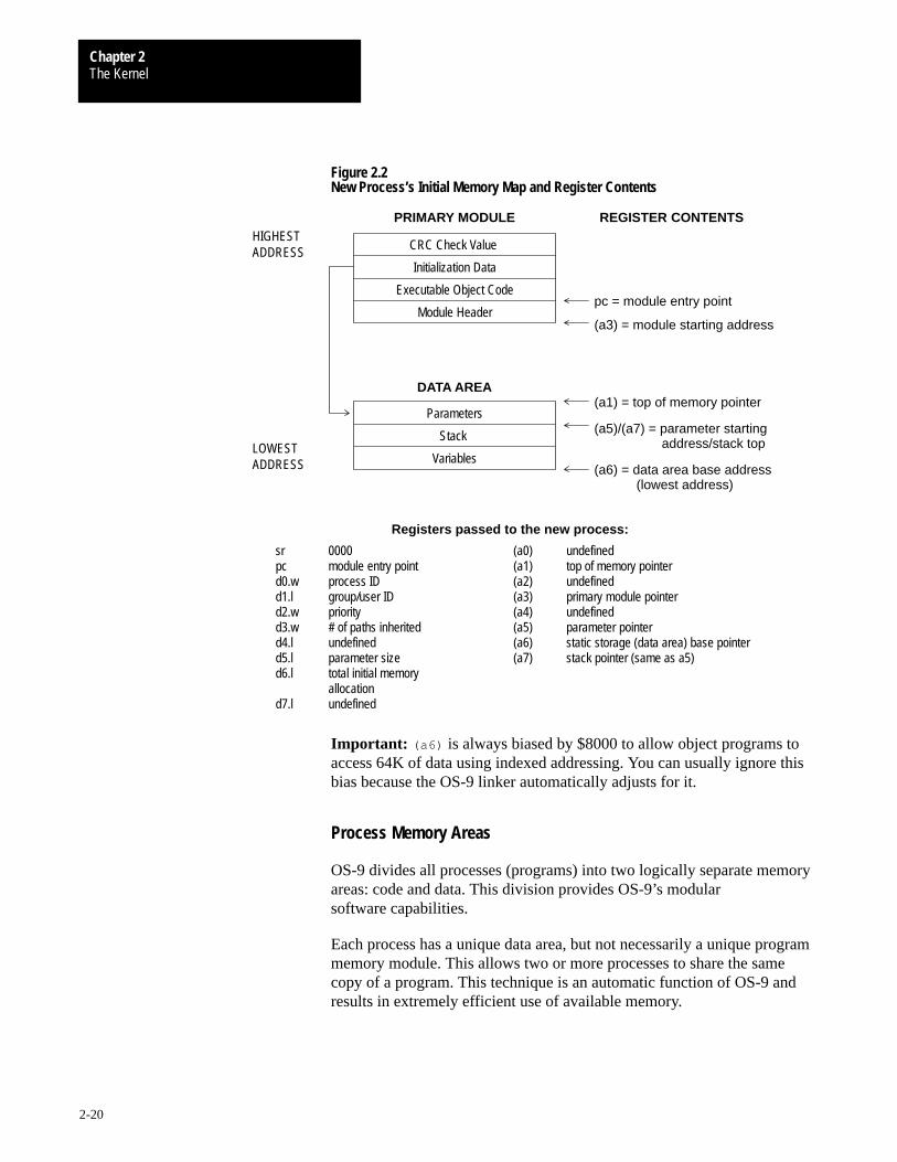
The KernelChapter 2
2-20
Figure 2.2New Process’s Initial Memory Map and Register Contents
PRIMARY MODULEHIGHEST
Initialization Data
Executable Object Code
Module Header
DATA AREA
Parameters
Stack
REGISTER CONTENTS
pc = module entry point
(a3) = module starting address
(a1) = top of memory pointer
(a6) = data area base address
Registers passed to the new process:
ADDRESS CRC Check Value
Variables
(a5)/(a7) = parameter starting
(lowest address)
address/stack topLOWEST ADDRESS
sr 0000 (a0) undefinedpc module entry point (a1) top of memory pointerd0.w process ID (a2) undefinedd1.l group/user ID (a3) primary module pointerd2.w priority (a4) undefinedd3.w # of paths inherited (a5) parameter pointerd4.l undefined (a6) static storage (data area) base pointerd5.l parameter size (a7) stack pointer (same as a5)d6.l total initial memory
allocationd7.l undefined
Important: (a6) is always biased by $8000 to allow object programs toaccess 64K of data using indexed addressing. You can usually ignore thisbias because the OS-9 linker automatically adjusts for it.
Process Memory Areas
OS-9 divides all processes (programs) into two logically separate memoryareas: code and data. This division provides OS-9’s modularsoftware capabilities.
Each process has a unique data area, but not necessarily a unique programmemory module. This allows two or more processes to share the samecopy of a program. This technique is an automatic function of OS-9 andresults in extremely efficient use of available memory.

The KernelChapter 2
2-21
A program must be in the form of an executable memory module(described in Chapter 1) to be run. The program is position-independentand ROMable, and the memory it occupies is considered read-only. It maylink to and execute code in other modules.
The process’s data area is a separate memory space where all of theprogram’s variables are kept. The top part of this area is used for theprogram’s stack. The actual memory addresses assigned to the data area areunknown at the time the program is written. A base address is kept in aregister (usually a6) to access the data area. You can read or write tothis area.
If a program uses variables that require initialization, OS-9 copies theinitial values from the read-only program area to the data area where thevariables actually reside. The OS-9 linker builds appropriate initializationtables which initialize the variables.
Process States
A process is either in active, waiting, or sleeping state:
Process: Description:
ACTIVE The process is active and ready for execution. The scheduler gives activeprocesses time for execution according to their relative priority withrespect to all other active processes. It uses a method that compares theages of all active processes in the queue. It gives some CPU time to allactive processes, even if they have a very low relative priority.
WAITING The process is inactive until a child process terminates or until a signal isreceived. The process enters the wait state when it executes a F$Waitsystem service request. It remains inactive until one of its descendantprocesses terminates or until it receives a signal.
SLEEPING The process is inactive for a specified period of time or until it receives asignal. A process enters the sleep state when it executes an F$Sleepservice request. F$Sleep specifies a time interval for which the process isto remain inactive. Processes often sleep to avoid wasting CPU time whilewaiting for some external event, such as the completion of I/O. Zero ticksspecifies an infinite period of time. Processes waiting on an event are alsoincluded in the sleep queue.
There is a separate queue (linked list of process descriptors) for eachprocess state. State changes are made by moving a process descriptor fromits current queue to another queue.
The KernelChapter 2
2-22
OS-9 is a multi-tasking operating system, that is, two or more independentprograms, called processes or tasks, can execute simultaneously. Severalprocesses share each second of CPU time. Although the processes appearto run continuously, the CPU only executes one instruction at a time. TheOS-9 kernel determines which process, and how long, to run based on thepriorities of the active processes. Task-switching is the action of switchingfrom the execution of one process to another. Task-switching does notaffect the programs’ execution.
A real-time clock interrupts the CPU at every tick . By default, a tick is .01second (10 milliseconds). At any occurrence of a tick, OS-9 can suspendexecution of one program and begin execution of another. The tick lengthis hardware dependent. Thus, to change the tick length, you must rewritethe clock driver and re-initialize the hardware.
A slice or time-slice is the longest amount of time a process will controlthe CPU before the kernel re-evaluates the active process queue. Bydefault, a slice is two ticks. You can change the number of ticks per sliceby adjusting the system global variable D_TSlice or by modifying theInit module.
To ensure efficiency, only processes on the active process queue areconsidered for execution. The active process queue is organized by processage, a count of how many task switches have occurred since the processentered the active queue plus the process’s initial priority. The oldestprocess is at the head of the queue. OS-9’s scheduling algorithm allocatessome execution time to each active process.
When a process is placed in the active queue, its age is set to the process’sassigned priority and the ages of all other processes increment. Ages neverincrement beyond $FFFF.
After the currently executing process’s time-slice, the kernel executes theprocess with the highest age.
Pre-emptive Task-switching
During critical real-time applications you sometimes need fast interruptresponse time. OS9 provides this by pre-empting the currently executingprocess when a process with a higher priority becomes active. The lowerpriority process loses the remainder of its time-slice and is re-inserted intothe active queue.
Task-switching is affected by two system global variables: D_MinPty(minimum priority) and D_MaxAge (maximum age). Both variables areinitially set in the Init module. Users with a group ID of zero (super users)can access both variables through the F$SetSys system call.
Process Scheduling
The KernelChapter 2
2-23
If a process’s priority or age is less than D_MinPty, the process is notconsidered for execution and is not aged. Usually, this variable is not used;it is set to zero.
ATTENTION: If the minimum system priority is set above thepriority of all running tasks, the system is completely shutdown. You must reset to recover. Therefore, it is crucial torestore D_MinPty to a normal level when the criticaltask(s) finishes.
D_MaxAge is the maximum age to which a process can increment. WhenD_MaxAge is activated, tasks are divided into two classes, high priorityand low priority:
High priority tasks receive all of the available CPU time and do not age.
Low priority tasks do not age past D_MaxAge. Low priority tasks arerun only when the high priority tasks are inactive. Usually, this variableis not used; it is set to zero.
Important: A system-state process is not pre-empted until it finishes,unless it voluntarily gives up its time-slice. This exception is made becausesystem-state processes may be executing critical routines that affect sharedsystem resources which may block other unrelated processes.
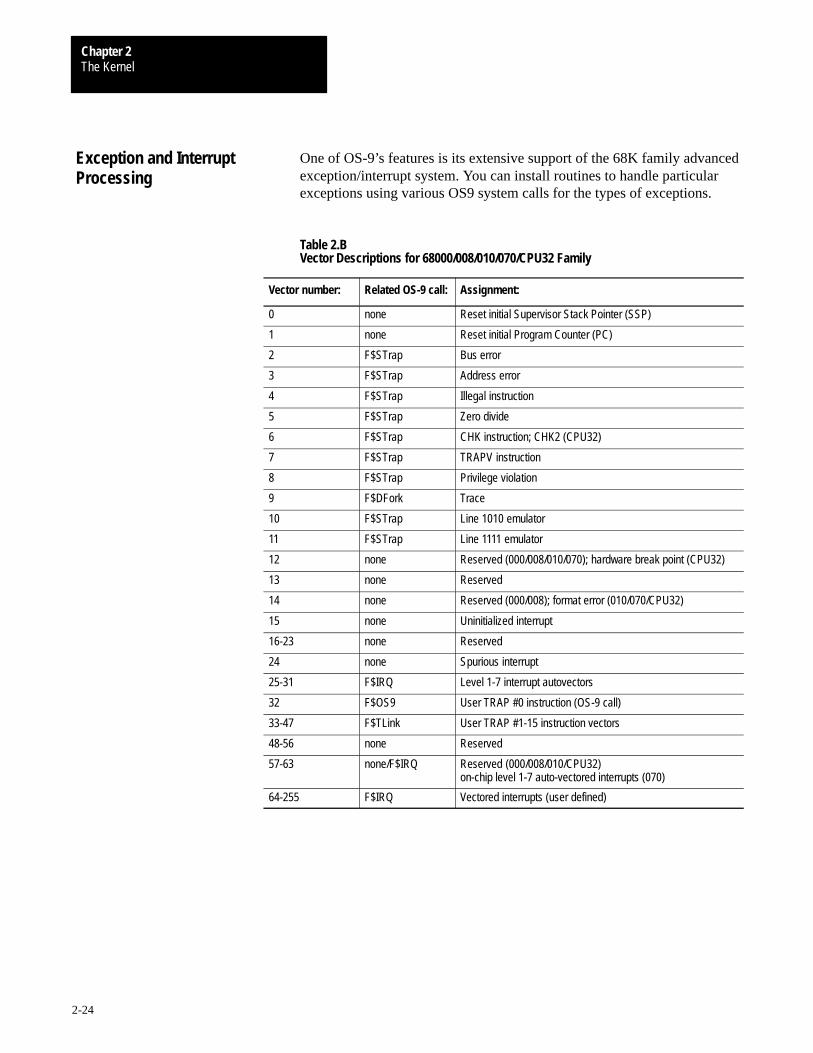
The KernelChapter 2
2-24
One of OS-9’s features is its extensive support of the 68K family advancedexception/interrupt system. You can install routines to handle particularexceptions using various OS9 system calls for the types of exceptions.
Table 2.BVector Descriptions for 68000/008/010/070/CPU32 Family
Vector number: Related OS-9 call: Assignment:
0 none Reset initial Supervisor Stack Pointer (SSP)
1 none Reset initial Program Counter (PC)
2 F$STrap Bus error
3 F$STrap Address error
4 F$STrap Illegal instruction
5 F$STrap Zero divide
6 F$STrap CHK instruction; CHK2 (CPU32)
7 F$STrap TRAPV instruction
8 F$STrap Privilege violation
9 F$DFork Trace
10 F$STrap Line 1010 emulator
11 F$STrap Line 1111 emulator
12 none Reserved (000/008/010/070); hardware break point (CPU32)
13 none Reserved
14 none Reserved (000/008); format error (010/070/CPU32)
15 none Uninitialized interrupt
16-23 none Reserved
24 none Spurious interrupt
25-31 F$IRQ Level 1-7 interrupt autovectors
32 F$OS9 User TRAP #0 instruction (OS-9 call)
33-47 F$TLink User TRAP #1-15 instruction vectors
48-56 none Reserved
57-63 none/F$IRQ Reserved (000/008/010/CPU32)on-chip level 1-7 auto-vectored interrupts (070)
64-255 F$IRQ Vectored interrupts (user defined)
Exception and InterruptProcessing

The KernelChapter 2
2-25
Table 2.CVector Descriptions for 68020/030/040
Vector number: Related OS-9 call: Assignment:
0 none Reset initial Supervisor Stack Pointer (SSP)
1 none Reset initial Program Counter (PC)
2 F$STrap Bus error
3 F$STrap Address error
4 F$STrap Illegal instruction
5 F$STrap Zero divide
6 F$STrap CHK, CHK2
7 F$STrap TRAPV cpTRAPcc, TRAPcc
8 F$STrap Privilege violation
9 F$DFork Trace
10 F$STrap Line 1010 emulator
11 F$STrap Line 1111 emulator
12 none Reserved
13 none Coprocessor protocol violation (020,030 only); reserved (040)
14 none Format error
15 none Uninitialized interrupt
16-23 none Reserved
24 none Spurious interrupt
25-31 F$IRQ Level 1-7 interrupt autovectors
32 F$OS9 User TRAP #0 instruction (OS-9 call)
33-47 F$TLink User TRAP #1-15 instruction vectors
48 F$STrap FPCP Branch, or set on unordered condition
49 F$STrap FPCP Inexact result
50 F$STrap FPCP Divide by zero
51 F$STrap FPCP Underflow error
52 F$STrap FPCP Operand error
53 F$STrap FPCP Overflow error
54 F$STrap FPCP NAN signaled
55 F$STrap Reserved (020/030); FPCP Unimplemented data type (040)
56 none PMMU Configuration (020/030); reserved (040)
57 none PMMU Illegal Operation (020); reserved (030/040)
58 none PMMU Access Level Violation (020); reserved (030/040)
59-63 none Reserved
64-255 F$IRQ Vectored interrupts (user defined)
The KernelChapter 2
2-26
Reset Vectors: vectors 0, 1
The reset initial SSP vector contains the address loaded into the system’sstack pointer at startup. There must be at least 4K of RAM below and 4Kof RAM above this address for system global storage. Each time anexception occurs, OS-9 uses this vector to find the base address of systemglobal data.
The reset initial program counter (PC) is the coldstart entry point to OS-9.After startup, its only use is to reset after a catastrophic failure.
ATTENTION: User programs should not use or modify eitherof these vectors.
Error Exceptions: vectors 2-8, 10-24, 48-63
These exceptions are usually considered fatal program errors and cause auser program to unconditionally terminate. If F$DFork created the process,the process resources remain intact and control returns to the parentdebugger to allow a postmortem examination.
You may use the F$STrap system call to install a user subroutine to catchthe errors in this group that are considered non-fatal.
When an error exception occurs, the user subroutine executes in user state,with a pointer to the normal data space used by the process and all userregisters stacked. The exception handler must decide whether and where tocontinue execution.
If any of these exceptions occur in system state, it usually means a systemcall was passed bad data and an error is returned. In some cases, systemdata structures are damaged by passing nonsense parameters tosystem calls.
Important: Not all catchable exception vectors are applicable to all68000-family CPUs. For example, vectors 48-54 (FPCP exceptions) onlyapply to 68020 and 68030 CPUs.
The Trace Exception: vector 9
The trace exception occurs when the status register trace bit is set. Thisallows the MPU to single step instructions. OS-9 provides the F$DFork,F$DExec, and F$DExit system calls to control program tracing.

The KernelChapter 2
2-27
AutoVectored Interrupts: vectors 25-31; 57-63 (68070 only)
These exceptions provide interrupt polling for I/O devices that do notgenerate vectored interrupts. Internally, they are handled exactly likevectored interrupts (see below).
ATTENTION: Normally, you should not use Level 7 interruptsbecause they are non-maskable and can interrupt the system atdangerous times. You may use Level 7 interrupts for softwarerefresh of dynamic RAMs or similar functions, provided that theIRQ service routine does not use any OS-9 system calls orsystem data structures.
User Traps: vectors 32-47
The system reserves user trap zero (vector 32) for standard OS-9 systemservice requests. The remaining 15 user traps provide a method to link tocommon library routines at execution time.
Library routines are similar to program object code modules and areallocated their own static storage when installed by the F$TLink servicerequest. The execution entry point executes whenever the user trap iscalled. In addition, trap handlers have initialization and termination entrypoints which execute when linked and at process termination. Thetermination entry point is not currently implemented.
Important: Trap 13 (CIO) and trap 15 (math) are standard trap handlersdistributed by Microware.
Vectored Interrupts: vectors 64-255
The 192 vectored interrupts provide a minimum amount of systemoverhead in calling a device driver module to handle an interrupt. Interruptservice routines execute in system state without an associated currentprocess. The device driver must provide an error entry point for the systemto execute if any error exceptions occur during interrupt processing,although this entry point is not currently implemented. The F$IRQ systemcall installs a handler in the system’s interrupt tables. If necessary, multipledevices may be used on the same vector.
Chapter
3
3-1
OS-9 Input/Output System
OS-9 features a versatile, unified, hardware-independent I/O system. TheI/O system is modular; you can easily expand or customize it. The OS-9I/O system consists of the following software components:
the kernel file managers device drivers the device descriptor
The kernel, file managers, and device drivers process I/O service requestsat different levels. The device descriptor contains information used toassemble the elements of a particular I/O subsystem. The file manager,device driver, and device descriptor modules are standard memorymodules. You can install or remove any of these modules while the systemis running.
The kernel supervises the overall OS-9 I/O system. The kernel:
maintains the I/O modules by managing various data structures. Itensures that the appropriate file manager and device driver modulesprocess each I/O request.
establishes paths. These are the connections between the kernel, theapplication, the file manager, and the device driver.
File managers perform the processing for a particular class of devices, suchas disks or terminals. They deal with “logical” operations on the class ofdevices. For example, the Random Block File manager (RBF) maintainsdirectory structures on disks; the Sequential Character File manager (SCF)edits the data stream it receives from terminals. File managers deal withthe I/O requests on a generic “class” basis.
Device drivers operate on a class of hardware. Operating on the actualhardware device, they send data to and from the device on behalf of the filemanager. They isolate the file manager from hardware dependencies suchas control register organization and data transfer modes, translating the filemanager’s logical requests into specific hardware operations.
The OS-9 UnifiedInput/Output System
OS-9 Input/Output SystemChapter 3
3-2
The device descriptor contains the information required to assemble thevarious components of an I/O subsystem (that is, a device). It contains thenames of the file manager and device driver associated with the device, aswell as the device’s operating parameters. Parameters in device descriptorscan be fixed, such as interrupt level and port address, or variable, such asterminal editing settings and disk physical parameters. The variableparameters in device descriptors provide the initial default values when apath is opened, but applications can change these values. The devicedescriptor name is the name of a device as known by the user. Forexample, the device /d0 is described by the device descriptor d0.
The kernel provides the first level of service for I/O system calls by routingdata between processes and the appropriate file managers and devicedrivers. The kernel also allocates and initializes global static storage onbehalf of file managers and device drivers.
The kernel maintains two important internal data structures: the devicetable and the path table. These tables reflect two other structuresrespectively: the device descriptor and the path descriptor.
When a path is opened, the kernel attempts to link to the device descriptorassociated with the device name specified (or implied) in the pathlist. Thedevice descriptor contains the names of the device driver and file managerfor the device. The information in the device descriptor is saved by thekernel in the device table so that it can route subsequent system calls tothese modules.
Paths maintain the status of I/O operations to devices and files. The kernelmaintains these paths using the path table. Each time a path is opened, apath descriptor is created and an entry is added to the path table. When apath is closed, the path descriptor is de-allocated and its entry is deletedfrom the path table.
When an I$Attach system call is first performed on a new devicedescriptor, the kernel creates a new entry in the device table. Each entry inthe table has specific information from the device descriptor concerningthe appropriate file manager and driver. It also contains a pointer to thedevice driver static storage. For each device in the table, the kernelmaintains a use count which indicates the current number of device users.
The Kernel and I/O
OS-9 Input/Output SystemChapter 3
3-3
Device Descriptor Modules
Device descriptor modules are small, non-executable modules that containinformation to associate a specific I/O device with its logical name,hardware controller address(es), device driver name, file manager name,and initialization parameters.
File managers operate on a class of logical devices. Device drivers operateon a class of physical devices. A device descriptor module tailors a devicedriver or file manager to a specific I/O port. At least one device descriptormodule must exist for each I/O device in the system. An I/O device mayhave several device descriptors with different initialization parameters andnames. For example, a serial/parallel driver could have two devicedescriptors, one for terminal operation (/T1) and one for printeroperation (/P1).
If a suitable device driver exists, adding devices to the system consists ofadding the new hardware and another device descriptor. Device descriptorscan be in ROM, in the boot file, or loaded into RAM while the system isrunning.
The name of the module is used as the logical device name by the systemand user (that is, it is the device name given in pathlists). Its formatconsists of a standard module header that has a type code of devicedescriptor (DEVIC). The remaining module header fields are shown inFigure 3.1 and described below.
Important: These fields are standard for all device descriptor modules.They are followed by a device specific initialization table. Refer toAppendix B of this manual for the initialization tables of each standardclass of I/O devices (RBF, SCF, SBF).

OS-9 Input/Output SystemChapter 3
3-4
Name: Description:
M$Port Port addressThe absolute physical address of the hardware controller.
M$Vector Interrupt vector numberThe interrupt vector associated with the port, used to initialize hardwareand for installation on the IRQ poll table:
25-31 for an auto-vectored interrupt. Levels 1-7. 57-63 for 68070 on-chip auto-vectored interrupts. Levels 1-7. 64-255 for a vectored interrupt.
M$IRQLvl Interrupt levelThe device’s physical interrupt level. It is not used by the kernel or filemanager. The device driver may use it to mask off interrupts for the devicewhen critical hardware manipulation occurs.
M$Prior Interrupt polling priorityIndicates the priority of the device on its vector. Smaller numbers arepolled first if more than one device is on the same vector. A priority of zeroindicates the device requires exclusive use of the vector.
M$Mode Device mode capabilitiesThis byte is used to validate a caller’s access mode byte in I$Create orI$Open calls. If the bit is set, the device is apable of performing thecorresponding function. If the Share_bit (single user bit) is set here, thedevice is non-sharable. This is useful for printers.
M$FMgr File manager name offsetThe offset to the name string of the file manager module for this device.
M$PDev Device driver name offsetThe offset to the name string of the device driver module for this device.
M$DevCon Device configurationThe offset to an optional device configuration table. You can use it tospecify parameters or flags that the device driver needs and are not partof the normal initialization table values. This table is located after thestandard initialization table. The kernel or file manager never references it.As the pointer to the device descriptor is passed in INIT and TERM,M$DevCon is generally available to the driver only during the driver’s INITand TERM routines. Other routines in the driver (for example, Read) mustfirst search the device table to locate the device descriptor before they canaccess this field.
Typically, this table is used for name string pointers, OEM global allocationpointers, or device-specific constants/flags.
NOTE: These values, unlike the standard options, are not copied into thepath descriptors options section.
M$Opt Table sizeThis contains the size of the device’s standard initialization table. Each filemanager defines a ceiling on M$Opt.
M$DTyp Device type (first field of initialization table)The device’s standard initialization table is defined by the file managerassociated with the device, with the exception of the first byte (M$DTyp).The first byte indicates the class of the device (RBF, SCF, etc.).
The initialization table (M$DTyp through M$DTyp + M$Opt) is copied intothe option section of the path descriptor when a path to the device isopened. Typically, this table is used for the default initialization parameterssuch as the delete and backspace characters for a terminal. Applicationsmay examine all of the values in this table using $GetStt (SS_Opt). Someof the values may be changed using I$SetStt; some are protected by thefile manager to prevent inappropriate changes.
The theoretical maximum initialization table size is 128 bytes. However, afile manager may restrict this to a smaller value.
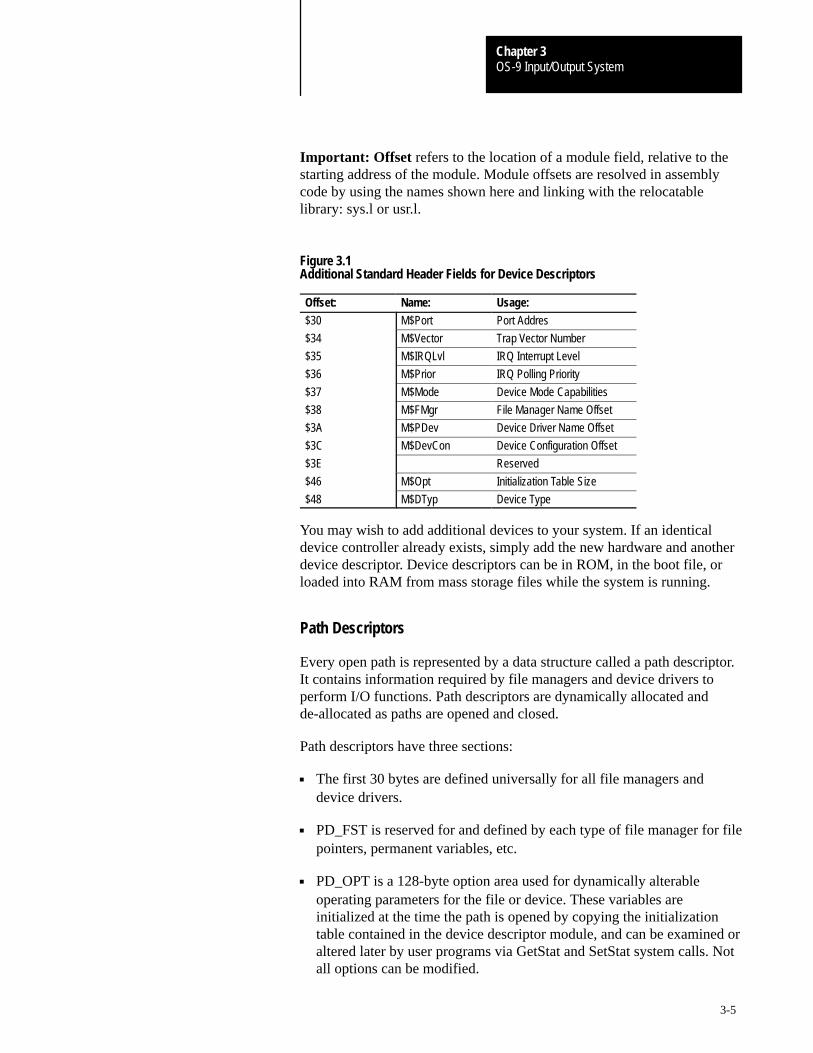
OS-9 Input/Output SystemChapter 3
3-5
Important: Offset refers to the location of a module field, relative to thestarting address of the module. Module offsets are resolved in assemblycode by using the names shown here and linking with the relocatablelibrary: sys.l or usr.l.
Figure 3.1Additional Standard Header Fields for Device Descriptors
Offset: Name: Usage:
$30 M$Port Port Addres
$34 M$Vector Trap Vector Number
$35 M$IRQLvl IRQ Interrupt Level
$36 M$Prior IRQ Polling Priority
$37 M$Mode Device Mode Capabilities
$38 M$FMgr File Manager Name Offset
$3A M$PDev Device Driver Name Offset
$3C M$DevCon Device Configuration Offset
$3E Reserved
$46 M$Opt Initialization Table Size
$48 M$DTyp Device Type
You may wish to add additional devices to your system. If an identicaldevice controller already exists, simply add the new hardware and anotherdevice descriptor. Device descriptors can be in ROM, in the boot file, orloaded into RAM from mass storage files while the system is running.
Path Descriptors
Every open path is represented by a data structure called a path descriptor.It contains information required by file managers and device drivers toperform I/O functions. Path descriptors are dynamically allocated andde-allocated as paths are opened and closed.
Path descriptors have three sections:
The first 30 bytes are defined universally for all file managers anddevice drivers.
PD_FST is reserved for and defined by each type of file manager for filepointers, permanent variables, etc.
PD_OPT is a 128-byte option area used for dynamically alterableoperating parameters for the file or device. These variables areinitialized at the time the path is opened by copying the initializationtable contained in the device descriptor module, and can be examined oraltered later by user programs via GetStat and SetStat system calls. Notall options can be modified.
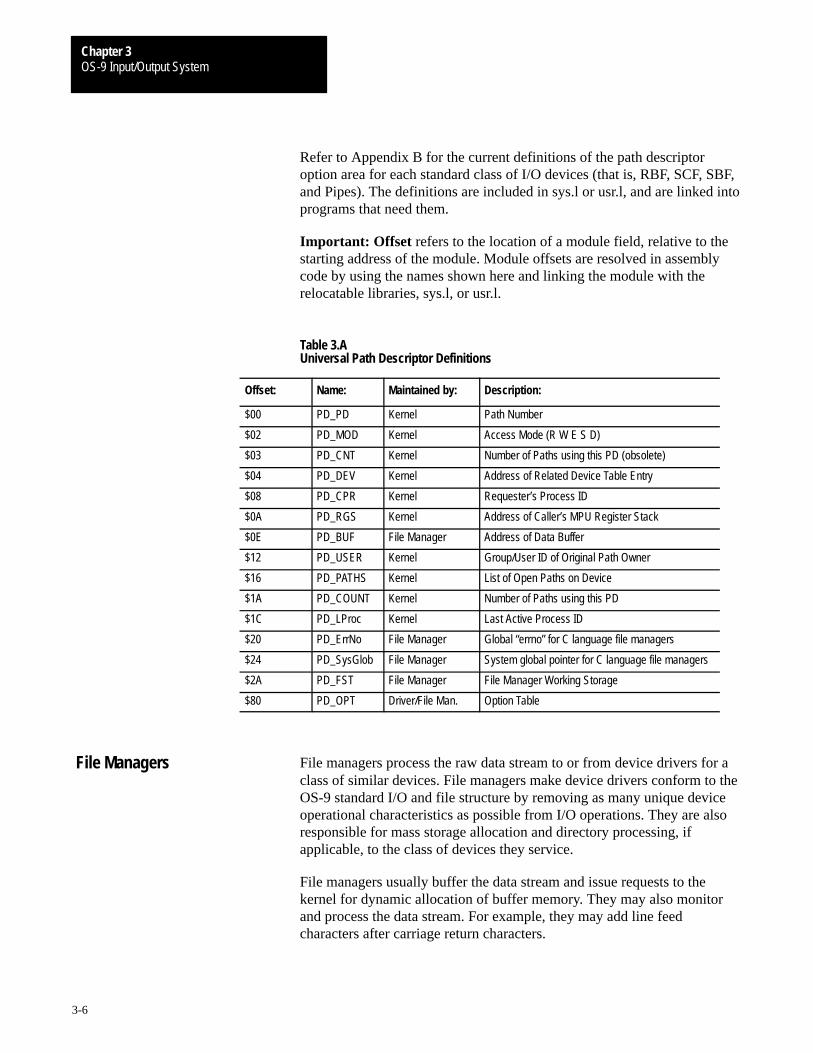
OS-9 Input/Output SystemChapter 3
3-6
Refer to Appendix B for the current definitions of the path descriptoroption area for each standard class of I/O devices (that is, RBF, SCF, SBF,and Pipes). The definitions are included in sys.l or usr.l, and are linked intoprograms that need them.
Important: Offset refers to the location of a module field, relative to thestarting address of the module. Module offsets are resolved in assemblycode by using the names shown here and linking the module with therelocatable libraries, sys.l, or usr.l.
Table 3.AUniversal Path Descriptor Definitions
Offset: Name: Maintained by: Description:
$00 PD_PD Kernel Path Number
$02 PD_MOD Kernel Access Mode (R W E S D)
$03 PD_CNT Kernel Number of Paths using this PD (obsolete)
$04 PD_DEV Kernel Address of Related Device Table Entry
$08 PD_CPR Kernel Requester’s Process ID
$0A PD_RGS Kernel Address of Caller’s MPU Register Stack
$0E PD_BUF File Manager Address of Data Buffer
$12 PD_USER Kernel Group/User ID of Original Path Owner
$16 PD_PATHS Kernel List of Open Paths on Device
$1A PD_COUNT Kernel Number of Paths using this PD
$1C PD_LProc Kernel Last Active Process ID
$20 PD_ErrNo File Manager Global “errno” for C language file managers
$24 PD_SysGlob File Manager System global pointer for C language file managers
$2A PD_FST File Manager File Manager Working Storage
$80 PD_OPT Driver/File Man. Option Table
File managers process the raw data stream to or from device drivers for aclass of similar devices. File managers make device drivers conform to theOS-9 standard I/O and file structure by removing as many unique deviceoperational characteristics as possible from I/O operations. They are alsoresponsible for mass storage allocation and directory processing, ifapplicable, to the class of devices they service.
File managers usually buffer the data stream and issue requests to thekernel for dynamic allocation of buffer memory. They may also monitorand process the data stream. For example, they may add line feedcharacters after carriage return characters.
File Managers

OS-9 Input/Output SystemChapter 3
3-7
File managers are re-entrant. One file manager may be used for an entireclass of devices having similar operational characteristics. OS-9 systemscan have any number of file manager modules.
Important: I/O system modules must have the followingmodule attributes:
They must be owned by a super-user (0.n).
They must have the system-state bit set in the attribute byte of themodule header. (OS-9 does not currently make use of this, but futurerevisions will require that I/O system modules be system-state modules.)
Four file managers are included in a typical OS-9 system:
RBF (Random Block File Manager)Operates random-access, block-structured devices such as disk systems.
SCF (Sequential Character File Manager)Used with single-character-oriented devices such as CRT or hardcopyterminals, printers, and modems.
SBF (Sequential Block File Manager)Used with sequential block-structured devices such as tape systems.
PIPEMAN (Pipe File Manager)Supports interprocess communication through memory bufferscalled pipes.
File Manager Organization
A file manager is a collection of major subroutines accessed through anoffset table. The table contains the starting address of each subroutinerelative to the beginning of the table. The location of the table is specifiedby the execution entry point offset in the module header. These routines arecalled in system state. A sample listing of the beginning of a file managermodule is listed in Figure 3.2.
When the individual file manager routines are called, standard parametersare passed in the following registers:
Parameter: Description:
(a1) Pointer to Path Descriptor
(a4) Pointer to current Process Descriptor
(a5) Pointer to User’s Register Stack; User registers pass/receive parametersas shown in the system call description section
(a6) Pointer to system Global Data area
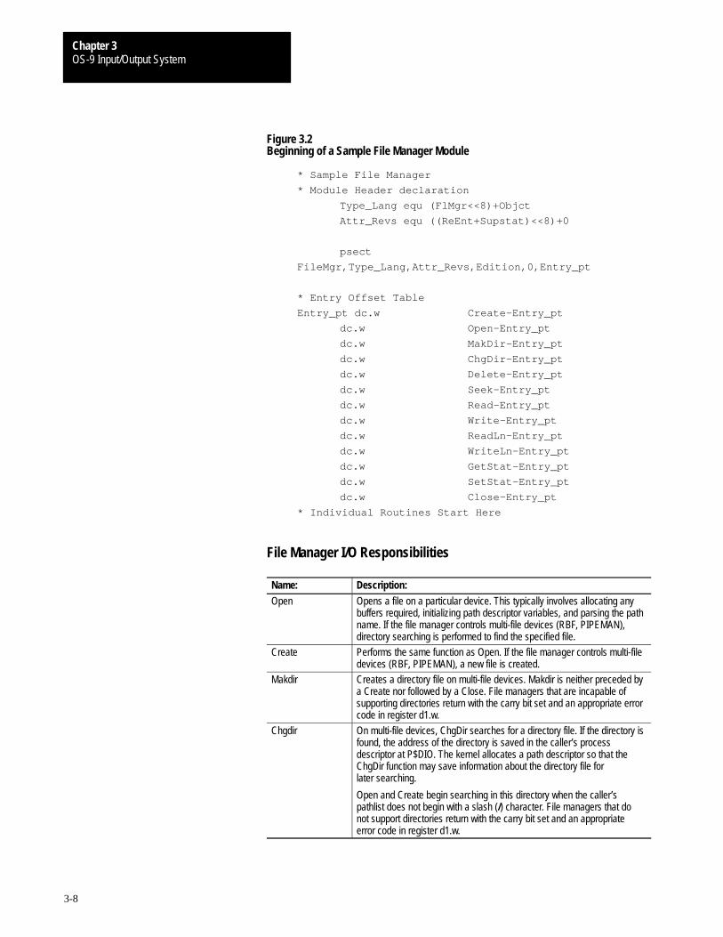
OS-9 Input/Output SystemChapter 3
3-8
Figure 3.2Beginning of a Sample File Manager Module
* Sample File Manager
* Module Header declaration
Type_Lang equ (FlMgr<<8)+Objct
Attr_Revs equ ((ReEnt+Supstat)<<8)+0
psect
FileMgr,Type_Lang,Attr_Revs,Edition,0,Entry_pt
* Entry Offset Table
Entry_pt dc.w Create–Entry_pt
dc.w Open–Entry_pt
dc.w MakDir–Entry_pt
dc.w ChgDir–Entry_pt
dc.w Delete–Entry_pt
dc.w Seek–Entry_pt
dc.w Read–Entry_pt
dc.w Write–Entry_pt
dc.w ReadLn–Entry_pt
dc.w WriteLn–Entry_pt
dc.w GetStat–Entry_pt
dc.w SetStat–Entry_pt
dc.w Close–Entry_pt
* Individual Routines Start Here
File Manager I/O Responsibilities
Name: Description:
Open Opens a file on a particular device. This typically involves allocating anybuffers required, initializing path descriptor variables, and parsing the pathname. If the file manager controls multi-file devices (RBF, PIPEMAN),directory searching is performed to find the specified file.
Create Performs the same function as Open. If the file manager controls multi-filedevices (RBF, PIPEMAN), a new file is created.
Makdir Creates a directory file on multi-file devices. Makdir is neither preceded bya Create nor followed by a Close. File managers that are incapable ofsupporting directories return with the carry bit set and an appropriate errorcode in register d1.w.
Chgdir On multi-file devices, ChgDir searches for a directory file. If the directory isfound, the address of the directory is saved in the caller’s processdescriptor at P$DIO. The kernel allocates a path descriptor so that theChgDir function may save information about the directory file forlater searching.
Open and Create begin searching in this directory when the caller’spathlist does not begin with a slash (/) character. File managers that donot support directories return with the carry bit set and an appropriateerror code in register d1.w.
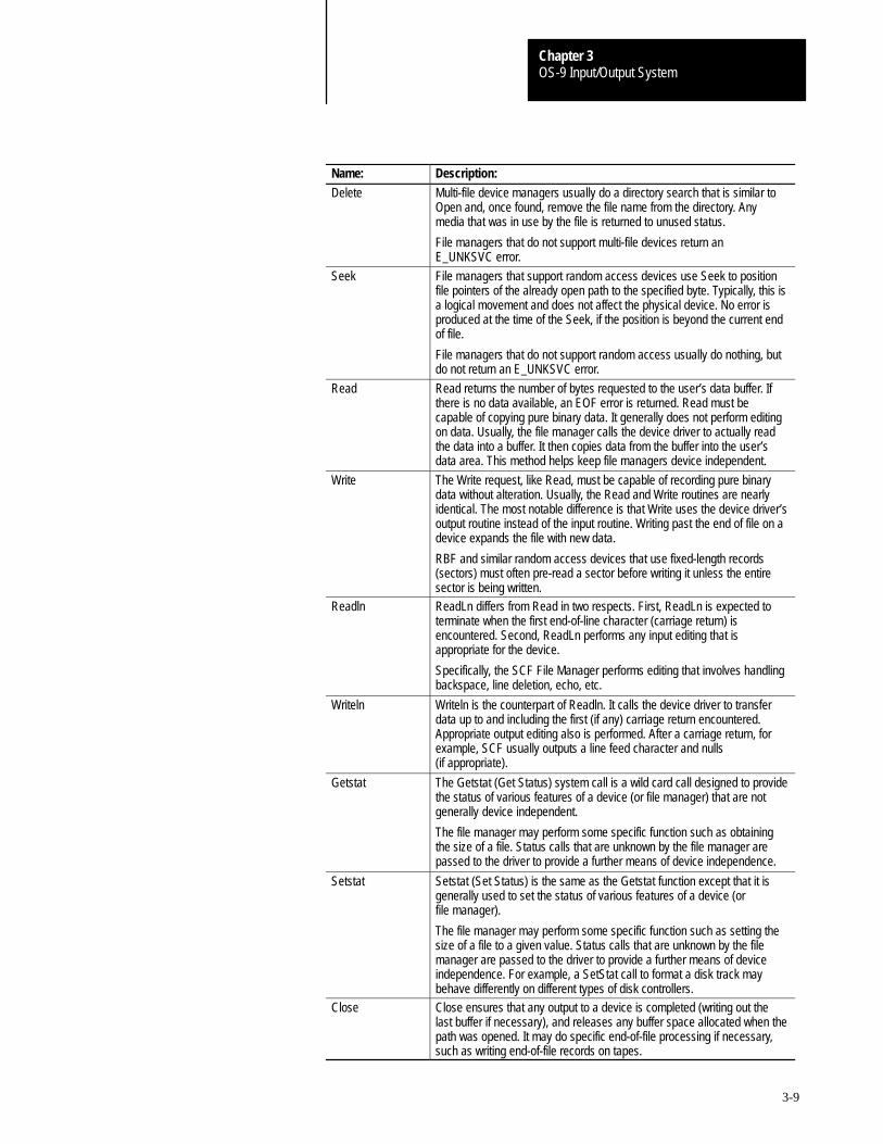
OS-9 Input/Output SystemChapter 3
3-9
Name: Description:
Delete Multi-file device managers usually do a directory search that is similar toOpen and, once found, remove the file name from the directory. Anymedia that was in use by the file is returned to unused status.
File managers that do not support multi-file devices return anE_UNKSVC error.
Seek File managers that support random access devices use Seek to positionfile pointers of the already open path to the specified byte. Typically, this isa logical movement and does not affect the physical device. No error isproduced at the time of the Seek, if the position is beyond the current endof file.
File managers that do not support random access usually do nothing, butdo not return an E_UNKSVC error.
Read Read returns the number of bytes requested to the user’s data buffer. Ifthere is no data available, an EOF error is returned. Read must becapable of copying pure binary data. It generally does not perform editingon data. Usually, the file manager calls the device driver to actually readthe data into a buffer. It then copies data from the buffer into the user’sdata area. This method helps keep file managers device independent.
Write The Write request, like Read, must be capable of recording pure binarydata without alteration. Usually, the Read and Write routines are nearlyidentical. The most notable difference is that Write uses the device driver’soutput routine instead of the input routine. Writing past the end of file on adevice expands the file with new data.
RBF and similar random access devices that use fixed-length records(sectors) must often pre-read a sector before writing it unless the entiresector is being written.
Readln ReadLn differs from Read in two respects. First, ReadLn is expected toterminate when the first end-of-line character (carriage return) isencountered. Second, ReadLn performs any input editing that isappropriate for the device.
Specifically, the SCF File Manager performs editing that involves handlingbackspace, line deletion, echo, etc.
Writeln Writeln is the counterpart of Readln. It calls the device driver to transferdata up to and including the first (if any) carriage return encountered.Appropriate output editing also is performed. After a carriage return, forexample, SCF usually outputs a line feed character and nulls(if appropriate).
Getstat The Getstat (Get Status) system call is a wild card call designed to providethe status of various features of a device (or file manager) that are notgenerally device independent.
The file manager may perform some specific function such as obtainingthe size of a file. Status calls that are unknown by the file manager arepassed to the driver to provide a further means of device independence.
Setstat Setstat (Set Status) is the same as the Getstat function except that it isgenerally used to set the status of various features of a device (orfile manager).
The file manager may perform some specific function such as setting thesize of a file to a given value. Status calls that are unknown by the filemanager are passed to the driver to provide a further means of deviceindependence. For example, a SetStat call to format a disk track maybehave differently on different types of disk controllers.
Close Close ensures that any output to a device is completed (writing out thelast buffer if necessary), and releases any buffer space allocated when thepath was opened. It may do specific end-of-file processing if necessary,such as writing end-of-file records on tapes.
OS-9 Input/Output SystemChapter 3
3-10
Device driver modules perform basic low-level physical input/outputfunctions. For example, a disk driver module’s basic functions are to reador write a physical sector. The driver is not concerned about files,directories, etc., which are handled at a higher level by the OS-9 filemanager. Because device driver modules are re-entrant, one copy of themodule can simultaneously support multiple devices that use identical I/Ocontroller hardware.
This section describes the function and general design of OS-9 devicedriver modules to aid programmers in modifying existing drivers orwriting new ones. To present this information in an understandablemanner, only basic drivers for character-oriented (SCF-type) anddisk-oriented (RBF-type) devices are discussed. We recommend that youstudy this section in conjunction with the individual device-specificsections and sample device driver source listings included in the OS-9Technical I/O Manual.
Basic Functional Requirements of Drivers
If written properly, a single physical driver module can handle multipleidentical hardware interfaces. The specific information for each physicalinterface (port address, initialization constants, etc.) is provided in thedevice descriptor module.
The name by which the device is known to the system is the name of thedevice descriptor module. OS-9 copies the initialization data of the devicedescriptor to the path descriptor data structure for easy access bythe drivers.
A device driver is actually a package of seven subroutines that are calledby a file manager in system state. Their functions are:
initialize the device controller hardware and related driver variablesas required
read a standard physical unit (a character or sector, depending on thedevice type)
write a standard physical unit (a character or sector, depending on thedevice type)
return a specified device status
set a specified device status
de-initialize the device. It is assumed that the device will not be usedagain unless re-initialized.
process an error exception generated during driver execution
Device Driver Modules
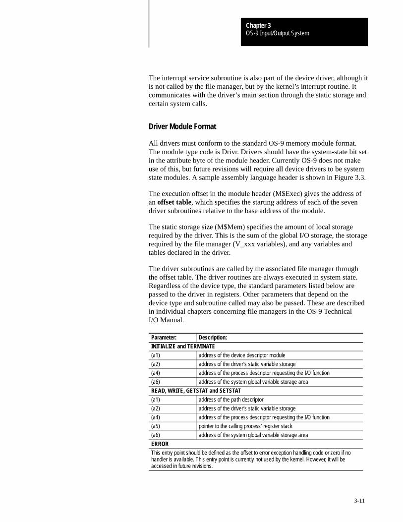
OS-9 Input/Output SystemChapter 3
3-11
The interrupt service subroutine is also part of the device driver, although itis not called by the file manager, but by the kernel’s interrupt routine. Itcommunicates with the driver’s main section through the static storage andcertain system calls.
Driver Module Format
All drivers must conform to the standard OS-9 memory module format.The module type code is Drivr. Drivers should have the system-state bit setin the attribute byte of the module header. Currently OS-9 does not makeuse of this, but future revisions will require all device drivers to be systemstate modules. A sample assembly language header is shown in Figure 3.3.
The execution offset in the module header (M$Exec) gives the address ofan offset table, which specifies the starting address of each of the sevendriver subroutines relative to the base address of the module.
The static storage size (M$Mem) specifies the amount of local storagerequired by the driver. This is the sum of the global I/O storage, the storagerequired by the file manager (V_xxx variables), and any variables andtables declared in the driver.
The driver subroutines are called by the associated file manager throughthe offset table. The driver routines are always executed in system state.Regardless of the device type, the standard parameters listed below arepassed to the driver in registers. Other parameters that depend on thedevice type and subroutine called may also be passed. These are describedin individual chapters concerning file managers in the OS-9 TechnicalI/O Manual.
Parameter: Description:
INITIALIZE and TERMINATE
(a1) address of the device descriptor module
(a2) address of the driver’s static variable storage
(a4) address of the process descriptor requesting the I/O function
(a6) address of the system global variable storage area
READ, WRITE, GETSTAT and SETSTAT
(a1) address of the path descriptor
(a2) address of the driver’s static variable storage
(a4) address of the process descriptor requesting the I/O function
(a5) pointer to the calling process’ register stack
(a6) address of the system global variable storage area
ERROR
This entry point should be defined as the offset to error exception handling code or zero if nohandler is available. This entry point is currently not used by the kernel. However, it will beaccessed in future revisions.
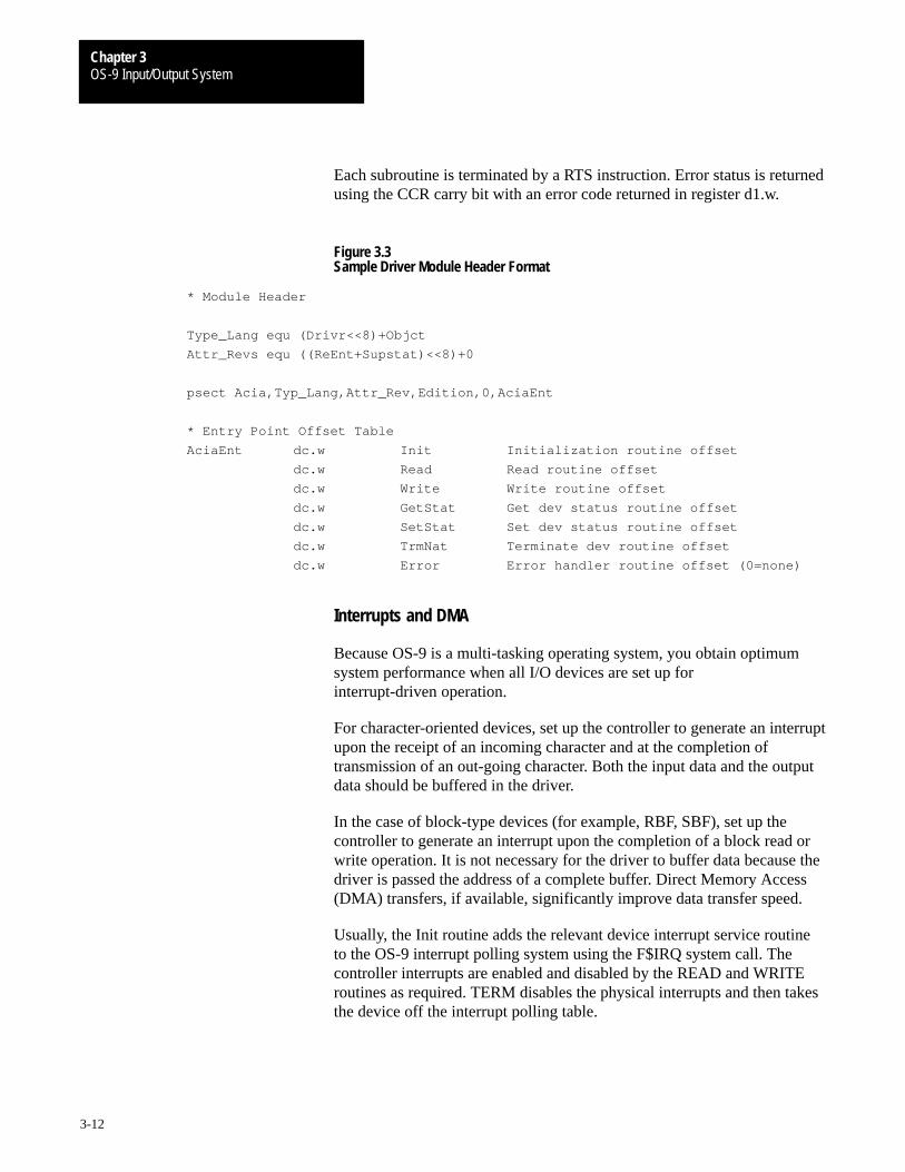
OS-9 Input/Output SystemChapter 3
3-12
Each subroutine is terminated by a RTS instruction. Error status is returnedusing the CCR carry bit with an error code returned in register d1.w.
Figure 3.3Sample Driver Module Header Format
* Module Header
Type_Lang equ (Drivr<<8)+Objct
Attr_Revs equ ((ReEnt+Supstat)<<8)+0
psect Acia,Typ_Lang,Attr_Rev,Edition,0,AciaEnt
* Entry Point Offset Table
AciaEnt dc.w Init Initialization routine offset
dc.w Read Read routine offset
dc.w Write Write routine offset
dc.w GetStat Get dev status routine offset
dc.w SetStat Set dev status routine offset
dc.w TrmNat Terminate dev routine offset
dc.w Error Error handler routine offset (0=none)
Interrupts and DMA
Because OS-9 is a multi-tasking operating system, you obtain optimumsystem performance when all I/O devices are set up forinterrupt-driven operation.
For character-oriented devices, set up the controller to generate an interruptupon the receipt of an incoming character and at the completion oftransmission of an out-going character. Both the input data and the outputdata should be buffered in the driver.
In the case of block-type devices (for example, RBF, SBF), set up thecontroller to generate an interrupt upon the completion of a block read orwrite operation. It is not necessary for the driver to buffer data because thedriver is passed the address of a complete buffer. Direct Memory Access(DMA) transfers, if available, significantly improve data transfer speed.
Usually, the Init routine adds the relevant device interrupt service routineto the OS-9 interrupt polling system using the F$IRQ system call. Thecontroller interrupts are enabled and disabled by the READ and WRITEroutines as required. TERM disables the physical interrupts and then takesthe device off the interrupt polling table.
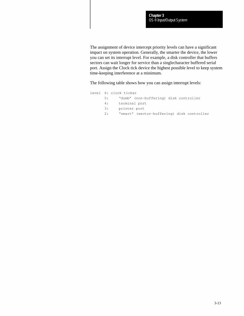
OS-9 Input/Output SystemChapter 3
3-13
The assignment of device intercept priority levels can have a significantimpact on system operation. Generally, the smarter the device, the loweryou can set its interrupt level. For example, a disk controller that bufferssectors can wait longer for service than a singlecharacter buffered serialport. Assign the Clock tick device the highest possible level to keep systemtime-keeping interference at a minimum.
The following table shows how you can assign interrupt levels:
level 6: clock ticker
5: “dumb” (non–buffering) disk controller
4: terminal port
3: printer port
2: “smart” (sector–buffering) disk controller
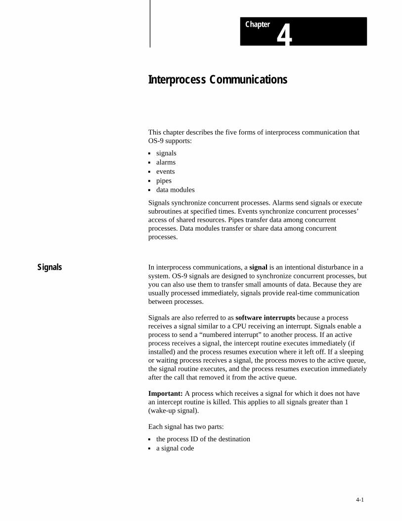
Chapter
4
4-1
Interprocess Communications
This chapter describes the five forms of interprocess communication thatOS-9 supports:
signals alarms events pipes data modules
Signals synchronize concurrent processes. Alarms send signals or executesubroutines at specified times. Events synchronize concurrent processes’access of shared resources. Pipes transfer data among concurrentprocesses. Data modules transfer or share data among concurrentprocesses.
In interprocess communications, a signal is an intentional disturbance in asystem. OS-9 signals are designed to synchronize concurrent processes, butyou can also use them to transfer small amounts of data. Because they areusually processed immediately, signals provide real-time communicationbetween processes.
Signals are also referred to as software interrupts because a processreceives a signal similar to a CPU receiving an interrupt. Signals enable aprocess to send a “numbered interrupt” to another process. If an activeprocess receives a signal, the intercept routine executes immediately (ifinstalled) and the process resumes execution where it left off. If a sleepingor waiting process receives a signal, the process moves to the active queue,the signal routine executes, and the process resumes execution immediatelyafter the call that removed it from the active queue.
Important: A process which receives a signal for which it does not havean intercept routine is killed. This applies to all signals greater than 1(wake-up signal).
Each signal has two parts:
the process ID of the destination a signal code
Signals
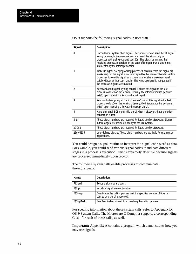
Interprocess CommunicationsChapter 4
4-2
OS-9 supports the following signal codes in user-state:
Signal: Description:
0 Unconditional system abort signal. The super-user can send the kill signalto any process, but non-super-users can send this signal only toprocesses with their group and user IDs. This signal terminates thereceiving process, regardless of the state of its signal mask, and is notintercepted by the intercept handler.
1 Wake-up signal. Sleeping/waiting processes which receive this signal areawakened, but the signal is not intercepted by the intercept handler. Activeprocesses ignore this signal. A program can receive a wake-up signalsafely without an intercept handler. The wake-up signal is not queued ifthe process’s signals are masked.
2 Keyboard abort signal. Typing control-E sends this signal to the lastprocess to do I/O on the terminal. Usually, the intercept routine performsexit(2) upon receiving a keyboard abort signal.
3 Keyboard interrupt signal. Typing control-C sends this signal to the lastprocess to do I/O on the terminal. Usually, the intercept routine performsexit(3) upon receiving a keyboard interrupt signal.
4 Hang-up signal. SCF sends this signal when it discovers that the modemconnection is lost.
5-31 These signal numbers are reserved for future use by Microware. Signalsin this range are considered deadly to the I/O system.
32-255 These signal numbers are reserved for future use by Microware.
256-65535 User-defined signals. These signal numbers are available for use in userapplications.
You could design a signal routine to interpret the signal code word as data.For example, you could send various signal codes to indicate differentstages in a process’s execution. This is extremely effective because signalsare processed immediately upon receipt.
The following system calls enable processes to communicatethrough signals:
Name: Description:
F$Send Sends a signal to a process.
F$Icpt Installs a signal intercept routine.
F$Sleep Deactivates the calling process until the specified number of ticks haspassed or a signal is received.
F$SigMask Enables/disables signals from reaching the calling process.
For specific information about these system calls, refer to Appendix D,OS-9 System Calls. The Microware C Compiler supports a correspondingC call for each of these calls, as well.
Important: Appendix A contains a program which demonstrates how youmay use signals.
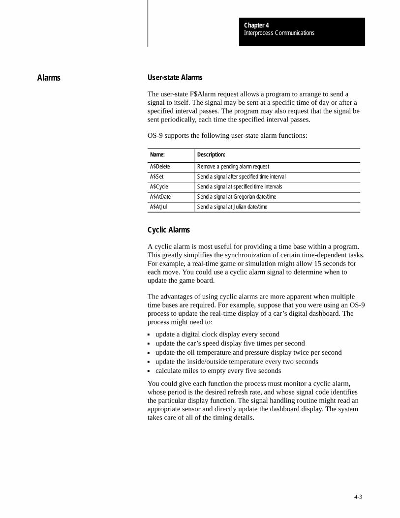
Interprocess CommunicationsChapter 4
4-3
User-state Alarms
The user-state F$Alarm request allows a program to arrange to send asignal to itself. The signal may be sent at a specific time of day or after aspecified interval passes. The program may also request that the signal besent periodically, each time the specified interval passes.
OS-9 supports the following user-state alarm functions:
Name: Description:
A$Delete Remove a pending alarm request
A$Set Send a signal after specified time interval
A$Cycle Send a signal at specified time intervals
A$AtDate Send a signal at Gregorian date/time
A$AtJul Send a signal at Julian date/time
Cyclic Alarms
A cyclic alarm is most useful for providing a time base within a program.This greatly simplifies the synchronization of certain time-dependent tasks.For example, a real-time game or simulation might allow 15 seconds foreach move. You could use a cyclic alarm signal to determine when toupdate the game board.
The advantages of using cyclic alarms are more apparent when multipletime bases are required. For example, suppose that you were using an OS-9process to update the real-time display of a car’s digital dashboard. Theprocess might need to:
update a digital clock display every second update the car’s speed display five times per second update the oil temperature and pressure display twice per second update the inside/outside temperature every two seconds calculate miles to empty every five seconds
You could give each function the process must monitor a cyclic alarm,whose period is the desired refresh rate, and whose signal code identifiesthe particular display function. The signal handling routine might read anappropriate sensor and directly update the dashboard display. The systemtakes care of all of the timing details.
Alarms
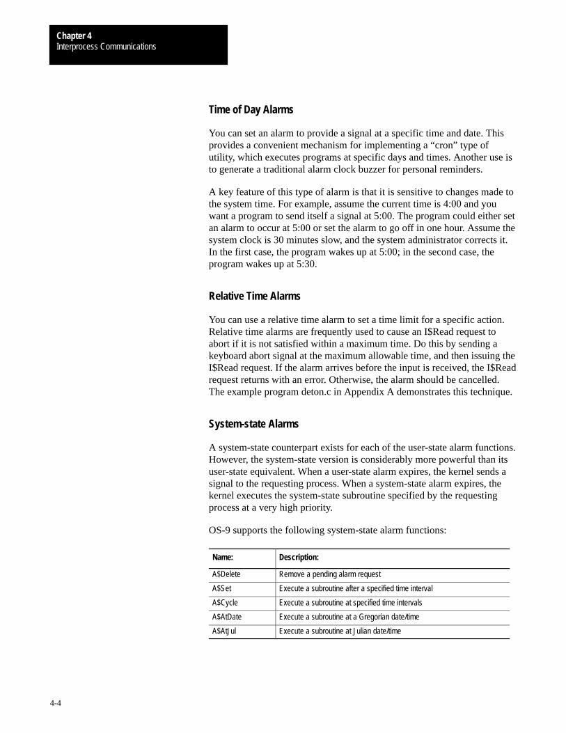
Interprocess CommunicationsChapter 4
4-4
Time of Day Alarms
You can set an alarm to provide a signal at a specific time and date. Thisprovides a convenient mechanism for implementing a “cron” type ofutility, which executes programs at specific days and times. Another use isto generate a traditional alarm clock buzzer for personal reminders.
A key feature of this type of alarm is that it is sensitive to changes made tothe system time. For example, assume the current time is 4:00 and youwant a program to send itself a signal at 5:00. The program could either setan alarm to occur at 5:00 or set the alarm to go off in one hour. Assume thesystem clock is 30 minutes slow, and the system administrator corrects it.In the first case, the program wakes up at 5:00; in the second case, theprogram wakes up at 5:30.
Relative Time Alarms
You can use a relative time alarm to set a time limit for a specific action.Relative time alarms are frequently used to cause an I$Read request toabort if it is not satisfied within a maximum time. Do this by sending akeyboard abort signal at the maximum allowable time, and then issuing theI$Read request. If the alarm arrives before the input is received, the I$Readrequest returns with an error. Otherwise, the alarm should be cancelled.The example program deton.c in Appendix A demonstrates this technique.
System-state Alarms
A system-state counterpart exists for each of the user-state alarm functions.However, the system-state version is considerably more powerful than itsuser-state equivalent. When a user-state alarm expires, the kernel sends asignal to the requesting process. When a system-state alarm expires, thekernel executes the system-state subroutine specified by the requestingprocess at a very high priority.
OS-9 supports the following system-state alarm functions:
Name: Description:
A$Delete Remove a pending alarm request
A$Set Execute a subroutine after a specified time interval
A$Cycle Execute a subroutine at specified time intervals
A$AtDate Execute a subroutine at a Gregorian date/time
A$AtJul Execute a subroutine at Julian date/time
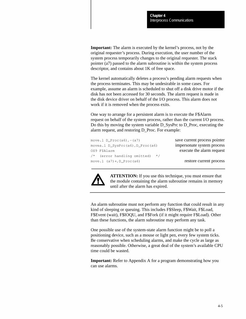
Interprocess CommunicationsChapter 4
4-5
Important: The alarm is executed by the kernel’s process, not by theoriginal requester’s process. During execution, the user number of thesystem process temporarily changes to the original requester. The stackpointer (a7) passed to the alarm subroutine is within the system processdescriptor, and contains about 1K of free space.
The kernel automatically deletes a process’s pending alarm requests whenthe process terminates. This may be undesirable in some cases. Forexample, assume an alarm is scheduled to shut off a disk drive motor if thedisk has not been accessed for 30 seconds. The alarm request is made inthe disk device driver on behalf of the I/O process. This alarm does notwork if it is removed when the process exits.
One way to arrange for a persistent alarm is to execute the F$Alarmrequest on behalf of the system process, rather than the current I/O process.Do this by moving the system variable D_SysPrc to D_Proc, executing thealarm request, and restoring D_Proc. For example:
move.l D_Proc(a6),–(a7) save current process pointermovea.l D_SysPrc(a6),D_Proc(a6) impersonate system processOS9 F$Alarm execute the alarm request/* (error handling omitted) */
move.l (a7)+,D_Proc(a6) restore current process
ATTENTION: If you use this technique, you must ensure thatthe module containing the alarm subroutine remains in memoryuntil after the alarm has expired.
An alarm subroutine must not perform any function that could result in anykind of sleeping or queuing. This includes F$Sleep, F$Wait, F$Load,F$Event (wait), F$IOQU, and F$Fork (if it might require F$Load). Otherthan these functions, the alarm subroutine may perform any task.
One possible use of the system-state alarm function might be to poll apositioning device, such as a mouse or light pen, every few system ticks.Be conservative when scheduling alarms, and make the cycle as large asreasonably possible. Otherwise, a great deal of the system’s available CPUtime could be wasted.
Important: Refer to Appendix A for a program demonstrating how youcan use alarms.
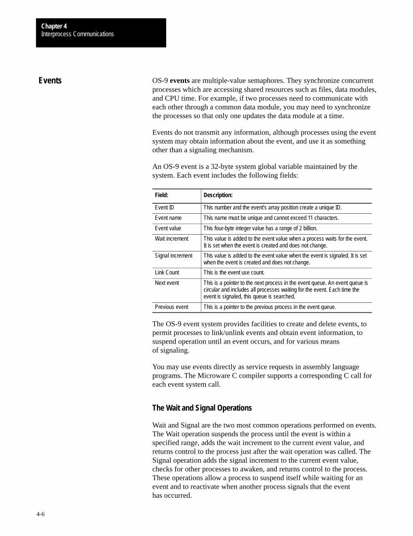
Interprocess CommunicationsChapter 4
4-6
OS-9 events are multiple-value semaphores. They synchronize concurrentprocesses which are accessing shared resources such as files, data modules,and CPU time. For example, if two processes need to communicate witheach other through a common data module, you may need to synchronizethe processes so that only one updates the data module at a time.
Events do not transmit any information, although processes using the eventsystem may obtain information about the event, and use it as somethingother than a signaling mechanism.
An OS-9 event is a 32-byte system global variable maintained by thesystem. Each event includes the following fields:
Field: Description:
Event ID This number and the event’s array position create a unique ID.
Event name This name must be unique and cannot exceed 11 characters.
Event value This four-byte integer value has a range of 2 billion.
Wait increment This value is added to the event value when a process waits for the event.It is set when the event is created and does not change.
Signal increment This value is added to the event value when the event is signaled. It is setwhen the event is created and does not change.
Link Count This is the event use count.
Next event This is a pointer to the next process in the event queue. An event queue iscircular and includes all processes waiting for the event. Each time theevent is signaled, this queue is searched.
Previous event This is a pointer to the previous process in the event queue.
The OS-9 event system provides facilities to create and delete events, topermit processes to link/unlink events and obtain event information, tosuspend operation until an event occurs, and for various meansof signaling.
You may use events directly as service requests in assembly languageprograms. The Microware C compiler supports a corresponding C call foreach event system call.
The Wait and Signal Operations
Wait and Signal are the two most common operations performed on events.The Wait operation suspends the process until the event is within aspecified range, adds the wait increment to the current event value, andreturns control to the process just after the wait operation was called. TheSignal operation adds the signal increment to the current event value,checks for other processes to awaken, and returns control to the process.These operations allow a process to suspend itself while waiting for anevent and to reactivate when another process signals that the eventhas occurred.
Events

Interprocess CommunicationsChapter 4
4-7
For example, you could use events to synchronize the use of a printer.Initialize the event value to one, the number of printers on the system. Setthe signal increment to one, and the wait increment to minus one (–1).When a process wants to use the printer, it checks to see if one is available,that is, it waits for the event value to be in the range (1, number ofprinters). In this example, the number of printers is one.
An event value within the specified range indicates that the printer isavailable; the printer is immediately marked as busy (that is, the eventvalue increases by –1, the wait increment) and the process is allowed to useit. An event value out of range indicates that the printer is busy and theprocess is put to sleep on the event queue.
When a process finishes with the printer, the process signals the event, thatis, it applies the signal increment to the event value. Then, the event queueis searched for a process whose event value range includes the currentevent value. If such a process is found, the process activates, applies thewait increment to the event value, and uses the printer.
To coordinate sharing a non-sharable resource, user programs must:
wait for the resource to become available mark the resource as busy use the resource signal that the resource is no longer busy
The first two steps in this process must be indivisible, because oftime-slicing. Otherwise, two processes could check an event and find itfree. Then, both processes would try to mark it busy. This corresponds totwo processes using a printer at the same time. The F$Event servicerequest prevents this from happening by performing both steps in theWait operation.
Important: Appendix A includes a program which demonstrates how youmay use events.
The F$Event System Call
The F$Event system call provides the mechanism to create named eventsfor this type of application. The name “event” was chosen instead of“semaphore” because F$Event provides the flexibility to synchronizeprocesses in a variety of ways not usually found in semaphore primitives.OS-9’s event routines are very efficient, and suitable for use in real-timecontrol applications.
Event variables require several maintenance functions as well as the Signaland Wait operations. To keep the number of system calls required to aminimum, all event operations are accessible through the F$Eventsystem call.
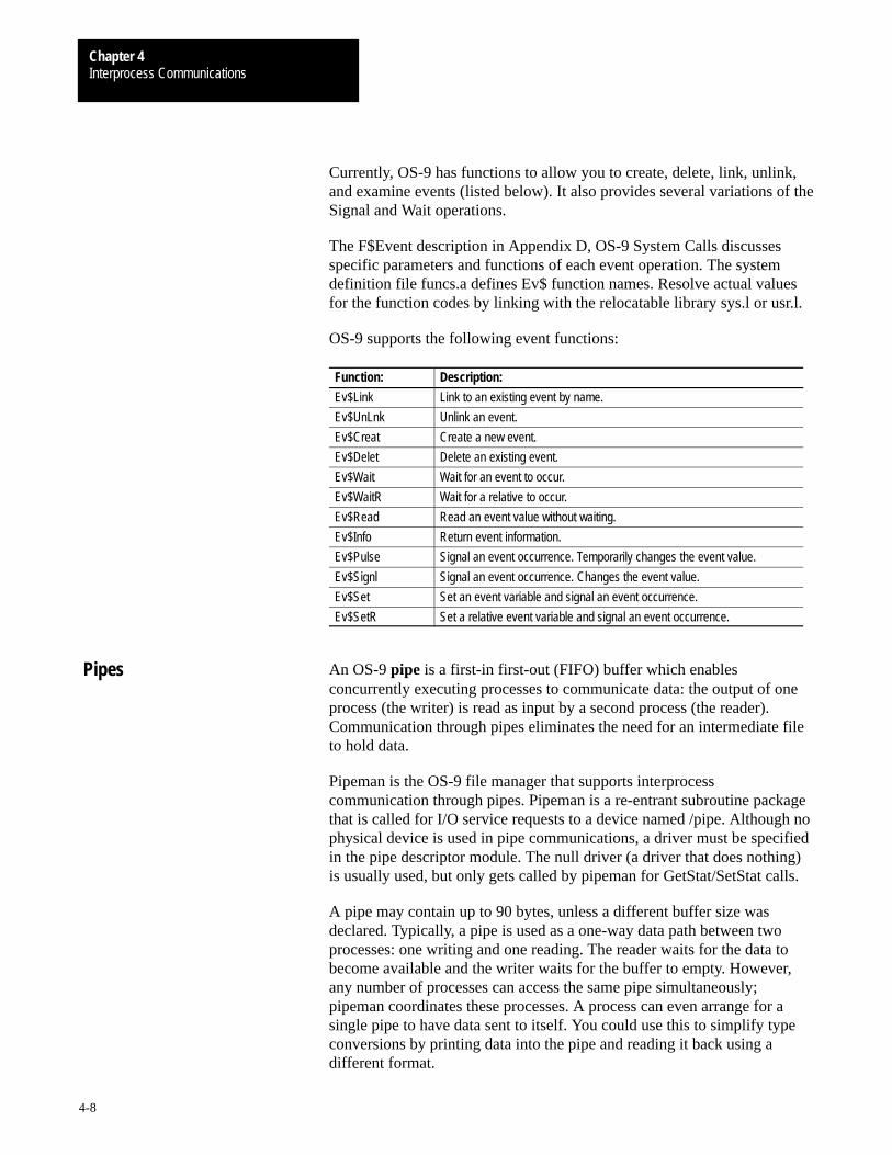
Interprocess CommunicationsChapter 4
4-8
Currently, OS-9 has functions to allow you to create, delete, link, unlink,and examine events (listed below). It also provides several variations of theSignal and Wait operations.
The F$Event description in Appendix D, OS-9 System Calls discussesspecific parameters and functions of each event operation. The systemdefinition file funcs.a defines Ev$ function names. Resolve actual valuesfor the function codes by linking with the relocatable library sys.l or usr.l.
OS-9 supports the following event functions:
Function: Description:
Ev$Link Link to an existing event by name.
Ev$UnLnk Unlink an event.
Ev$Creat Create a new event.
Ev$Delet Delete an existing event.
Ev$Wait Wait for an event to occur.
Ev$WaitR Wait for a relative to occur.
Ev$Read Read an event value without waiting.
Ev$Info Return event information.
Ev$Pulse Signal an event occurrence. Temporarily changes the event value.
Ev$Signl Signal an event occurrence. Changes the event value.
Ev$Set Set an event variable and signal an event occurrence.
Ev$SetR Set a relative event variable and signal an event occurrence.
An OS-9 pipe is a first-in first-out (FIFO) buffer which enablesconcurrently executing processes to communicate data: the output of oneprocess (the writer) is read as input by a second process (the reader).Communication through pipes eliminates the need for an intermediate fileto hold data.
Pipeman is the OS-9 file manager that supports interprocesscommunication through pipes. Pipeman is a re-entrant subroutine packagethat is called for I/O service requests to a device named /pipe. Although nophysical device is used in pipe communications, a driver must be specifiedin the pipe descriptor module. The null driver (a driver that does nothing)is usually used, but only gets called by pipeman for GetStat/SetStat calls.
A pipe may contain up to 90 bytes, unless a different buffer size wasdeclared. Typically, a pipe is used as a one-way data path between twoprocesses: one writing and one reading. The reader waits for the data tobecome available and the writer waits for the buffer to empty. However,any number of processes can access the same pipe simultaneously;pipeman coordinates these processes. A process can even arrange for asingle pipe to have data sent to itself. You could use this to simplify typeconversions by printing data into the pipe and reading it back using adifferent format.
Pipes
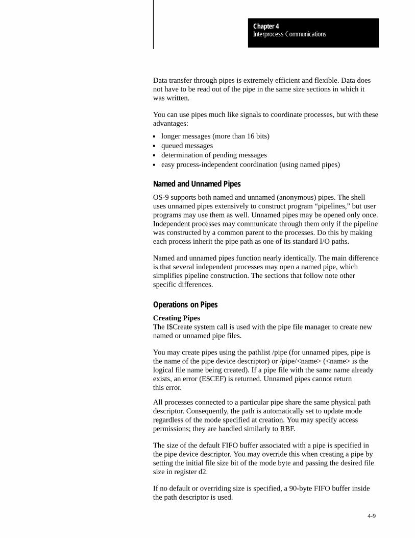
Interprocess CommunicationsChapter 4
4-9
Data transfer through pipes is extremely efficient and flexible. Data doesnot have to be read out of the pipe in the same size sections in which itwas written.
You can use pipes much like signals to coordinate processes, but with theseadvantages:
longer messages (more than 16 bits) queued messages determination of pending messages easy process-independent coordination (using named pipes)
Named and Unnamed Pipes
OS-9 supports both named and unnamed (anonymous) pipes. The shelluses unnamed pipes extensively to construct program “pipelines,” but userprograms may use them as well. Unnamed pipes may be opened only once.Independent processes may communicate through them only if the pipelinewas constructed by a common parent to the processes. Do this by makingeach process inherit the pipe path as one of its standard I/O paths.
Named and unnamed pipes function nearly identically. The main differenceis that several independent processes may open a named pipe, whichsimplifies pipeline construction. The sections that follow note otherspecific differences.
Operations on Pipes
Creating PipesThe I$Create system call is used with the pipe file manager to create newnamed or unnamed pipe files.
You may create pipes using the pathlist /pipe (for unnamed pipes, pipe isthe name of the pipe device descriptor) or /pipe/<name> (<name> is thelogical file name being created). If a pipe file with the same name alreadyexists, an error (E$CEF) is returned. Unnamed pipes cannot returnthis error.
All processes connected to a particular pipe share the same physical pathdescriptor. Consequently, the path is automatically set to update moderegardless of the mode specified at creation. You may specify accesspermissions; they are handled similarly to RBF.
The size of the default FIFO buffer associated with a pipe is specified inthe pipe device descriptor. You may override this when creating a pipe bysetting the initial file size bit of the mode byte and passing the desired filesize in register d2.
If no default or overriding size is specified, a 90-byte FIFO buffer insidethe path descriptor is used.
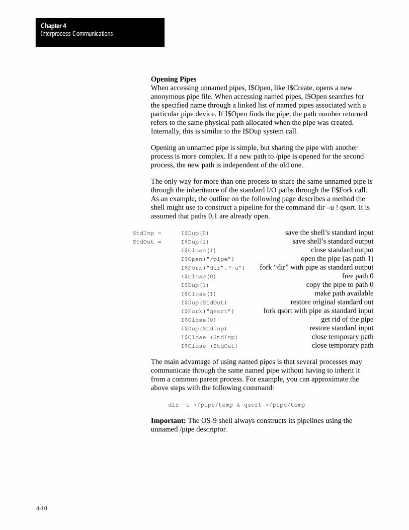
Interprocess CommunicationsChapter 4
4-10
Opening PipesWhen accessing unnamed pipes, I$Open, like I$Create, opens a newanonymous pipe file. When accessing named pipes, I$Open searches forthe specified name through a linked list of named pipes associated with aparticular pipe device. If I$Open finds the pipe, the path number returnedrefers to the same physical path allocated when the pipe was created.Internally, this is similar to the I$Dup system call.
Opening an unnamed pipe is simple, but sharing the pipe with anotherprocess is more complex. If a new path to /pipe is opened for the secondprocess, the new path is independent of the old one.
The only way for more than one process to share the same unnamed pipe isthrough the inheritance of the standard I/O paths through the F$Fork call.As an example, the outline on the following page describes a method theshell might use to construct a pipeline for the command dir –u ! qsort. It isassumed that paths 0,1 are already open.
StdInp = I$Dup(0) save the shell’s standard inputStdOut = I$Dup(1) save shell’s standard output
I$Close(1) close standard outputI$Open(“/pipe”) open the pipe (as path 1)I$Fork(“dir”,“–u”) fork “dir” with pipe as standard outputI$Close(0) free path 0I$Dup(1) copy the pipe to path 0I$Close(1) make path availableI$Dup(StdOut) restore original standard outI$Fork(“qsort”) fork qsort with pipe as standard inputI$Close(0) get rid of the pipeI$Dup(StdInp) restore standard inputI$Close (StdInp) close temporary pathI$Close (StdOut) close temporary path
The main advantage of using named pipes is that several processes maycommunicate through the same named pipe without having to inherit itfrom a common parent process. For example, you can approximate theabove steps with the following command:
dir –u >/pipe/temp & qsort </pipe/temp
Important: The OS-9 shell always constructs its pipelines using theunnamed /pipe descriptor.
Interprocess CommunicationsChapter 4
4-11
Read/ReadLnThe I$Read and I$ReadLn system calls return the next bytes in the pipebuffer. If there is not enough data ready to satisfy the request, the processreading the pipe is put to sleep until more data is available.
The end-of-file is recognized when the pipe is empty and the number ofprocesses waiting to read the pipe is equal to the number of users on thepipe. If any data was read before end-of-file was reached, an end-of-fileerror is not returned. However, the byte count returned is the number ofbytes actually transferred, which is less than the number requested.
Important: The Read and Write system calls are faster than ReadLn andWritLn because pipeman does not have to check for carriage returns andthe loops moving data are tighter.
Write/WriteLnThe I$Write and I$WritLn system calls work in almost the same way asI$Read and I$ReadLn. A pipe error (E$Write) is returned when all theprocesses with a full unnamed pipe open are attempting to write to thepipe. Each process attempting to write to the pipe receives the error, andthe pipe remains full.
When named pipes are being used, pipeman never returns the E$Writeerror. If a named pipe gets full before a process that receives data from thepipe opens it, the process writing to the pipe is put to sleep until a processreads the pipe.
CloseWhen a pipe path is closed, its path count decreases. If no paths are leftopen on an unnamed pipe, its memory returns to the system. With namedpipes, its memory returns only if the pipe is empty. A non-empty pipe(with no open paths) is artificially kept open, waiting for another process toopen and read from the pipe. This permits you to use pipes as a type of atemporary, self-destructing RAM disk file.
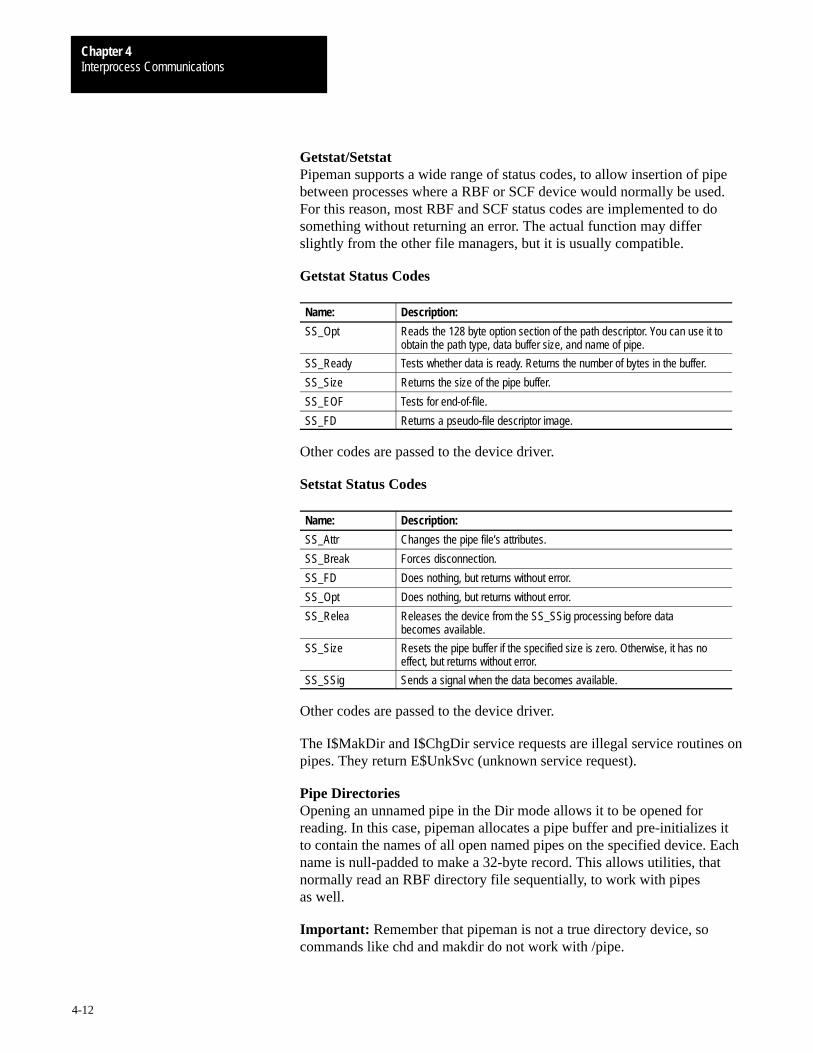
Interprocess CommunicationsChapter 4
4-12
Getstat/SetstatPipeman supports a wide range of status codes, to allow insertion of pipebetween processes where a RBF or SCF device would normally be used.For this reason, most RBF and SCF status codes are implemented to dosomething without returning an error. The actual function may differslightly from the other file managers, but it is usually compatible.
Getstat Status Codes
Name: Description:
SS_Opt Reads the 128 byte option section of the path descriptor. You can use it toobtain the path type, data buffer size, and name of pipe.
SS_Ready Tests whether data is ready. Returns the number of bytes in the buffer.
SS_Size Returns the size of the pipe buffer.
SS_EOF Tests for end-of-file.
SS_FD Returns a pseudo-file descriptor image.
Other codes are passed to the device driver.
Setstat Status Codes
Name: Description:
SS_Attr Changes the pipe file’s attributes.
SS_Break Forces disconnection.
SS_FD Does nothing, but returns without error.
SS_Opt Does nothing, but returns without error.
SS_Relea Releases the device from the SS_SSig processing before databecomes available.
SS_Size Resets the pipe buffer if the specified size is zero. Otherwise, it has noeffect, but returns without error.
SS_SSig Sends a signal when the data becomes available.
Other codes are passed to the device driver.
The I$MakDir and I$ChgDir service requests are illegal service routines onpipes. They return E$UnkSvc (unknown service request).
Pipe DirectoriesOpening an unnamed pipe in the Dir mode allows it to be opened forreading. In this case, pipeman allocates a pipe buffer and pre-initializes itto contain the names of all open named pipes on the specified device. Eachname is null-padded to make a 32-byte record. This allows utilities, thatnormally read an RBF directory file sequentially, to work with pipesas well.
Important: Remember that pipeman is not a true directory device, socommands like chd and makdir do not work with /pipe.
Interprocess CommunicationsChapter 4
4-13
The head of a linked list of named pipes is in the static storage of the pipedevice driver (usually the null driver). If there are several pipe descriptorswith different default pipe buffer sizes on a system, the I/O system noticesthat the same file manager, device driver, and port address (usually zero)are being used. It will not allocate new static storage for each pipe deviceand all named pipes will be on the same list.
For example, if two pipe descriptors exist, a directory of either devicereveals all the named pipes for both devices. If each pipe descriptor has aunique port address (0,1,...), the I/O system allocates different staticstorage for each pipe device. This produces more predictable results.
OS-9 data modules enable multiple processes to share a data area and totransfer data among themselves. A data module must have a valid CRCand module header to be loaded. A data module can be non-re-entrant; itcan modify itself and be modified by several processes.
OS-9 does not have restrictions as to the content, organization, or usage ofthe data area in a data module. These considerations are determined by theprocesses using the data module.
OS-9 does not synchronize processes using a data module. Consequently,thoughtful programming, usually involving events or signals, is required toenable several processes to update a shared data module simultaneously.
Creating Data Modules
The F$DatMod system call creates a data module with a specified set ofattributes, data area size, and module name. The data area is clearedautomatically. The data module is created with a valid CRC and enteredinto the system module directory.
Important: It is essential that the data module’s header and name stringnot be modified to prevent the module from becoming unknown tothe system.
The Microware C compiler provides several C calls to create and use datamodules directly. These include the _mkdata_module() call, which isspecific to data modules, and the modlink(), modload(), munlink(), andmunload() facilities which apply to all OS-9 modules. For moreinformation on these calls, refer to the standard library sections of the OS-9C Compiler User’s Manual.
Data Modules
Interprocess CommunicationsChapter 4
4-14
The Link Count
Like all OS-9 modules, data modules have a link count associated withthem. The link count is a counter of how many processes are currentlylinked to the module. Generally, the module is taken out of memory whenthis count reaches zero. If you want the module to remain in memory whenthe link count is zero, when you create the module make it “sticky” bysetting the sticky bit in its attribute byte.
Saving to Disk
If a data module is saved to disk, you can use the dump utility to examinethe module’s format and contents. You can save a data module to diskusing the save utility or by writing the module image into a file. If the datamodule was modified since its creation, the saved module’s CRC is badand it is impossible to re-load it into memory. To re-load the module, usethe F$SetCRC system call or _setcrc() C library call before writing it todisk. Or, use the fixmod utility after the module has been written to disk.
Chapter
5
5-1
User Trap Handlers
The 68000 family of microprocessors has sixteen software trap exceptionvectors. The first (trap 0) is reserved for making OS-9 system calls. Youmay use the remaining fifteen as service requests to user-defined “usertrap handlers.”
Microware provides standard trap handlers for I/O conversions in the Clanguage, floating point math, and trigonometric functions. The followingtraps are reserved:
Trap: Description:
trap 13 CIO is automatically called for any C program.
trap 15 Math is called for floating point math, extended integer math and/or typeconversion. It is also used for programs using transcendental and/orextended mathematical functions.
For further information about the math module, refer to Chapter 6.
A user trap handler is an OS-9 module that usually contains a set ofrelated subroutines. Any user program may dynamically link to the usertrap handler and call it at execution time.
Important: While trap handlers reduce the size of the execution program,they do not do anything that could not be done by linking the program withappropriate library routines at compilation time. In fact, programs that calltrap handlers execute slightly slower than linked programs that perform thesame function.
Trap handlers must be written in a language that compiles to machine code(such as assembly language or C). They should be suitably generic for useby a number of programs.
Trap handlers are similar to normal OS-9 program modules, except thattrap handlers have three execution entry points: a trap execution entrypoint, trap initialization entry point, and trap termination entry point.
Trap handler modules are of module type TrapLib and modulelanguage Objct.
The trap module routines usually execute as though they were called with ajsr instruction, except for minor stack differences. Any system calls orother operations that the calling module could perform are usable in thetrap module.
Trap Handlers
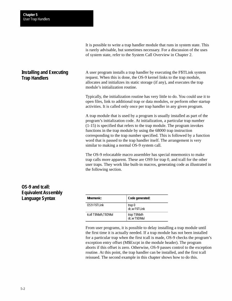
User Trap HandlersChapter 5
5-2
It is possible to write a trap handler module that runs in system state. Thisis rarely advisable, but sometimes necessary. For a discussion of the usesof system state, refer to the System Call Overview in Chapter 2.
A user program installs a trap handler by executing the F$TLink systemrequest. When this is done, the OS-9 kernel links to the trap module,allocates and initializes its static storage (if any), and executes the trapmodule’s initialization routine.
Typically, the initialization routine has very little to do. You could use it toopen files, link to additional trap or data modules, or perform other startupactivities. It is called only once per trap handler in any given program.
A trap module that is used by a program is usually installed as part of theprogram’s initialization code. At initialization, a particular trap number(1-15) is specified that refers to the trap module. The program invokesfunctions in the trap module by using the 68000 trap instructioncorresponding to the trap number specified. This is followed by a functionword that is passed to the trap handler itself. The arrangement is verysimilar to making a normal OS-9 system call.
The OS-9 relocatable macro assembler has special mnemonics to maketrap calls more apparent. These are OS9 for trap 0, and tcall for the otheruser traps. They work like built-in macros, generating code as illustrated inthe following section.
Mnemonic: Code generated:
OS9 F$TLink trap 0dc.w F$TLink
tcall T$Math,T$DMul trap T$Mathdc.w T$DMul
From user programs, it is possible to delay installing a trap module untilthe first time it is actually needed. If a trap module has not been installedfor a particular trap when the first tcall is made, OS-9 checks the program’sexception entry offset (M$Excpt in the module header). The programaborts if this offset is zero. Otherwise, OS-9 passes control to the exceptionroutine. At this point, the trap handler can be installed, and the first tcallreissued. The second example in this chapter shows how to do this.
Installing and ExecutingTrap Handlers
OS-9 and tcall:Equivalent AssemblyLanguage Syntax
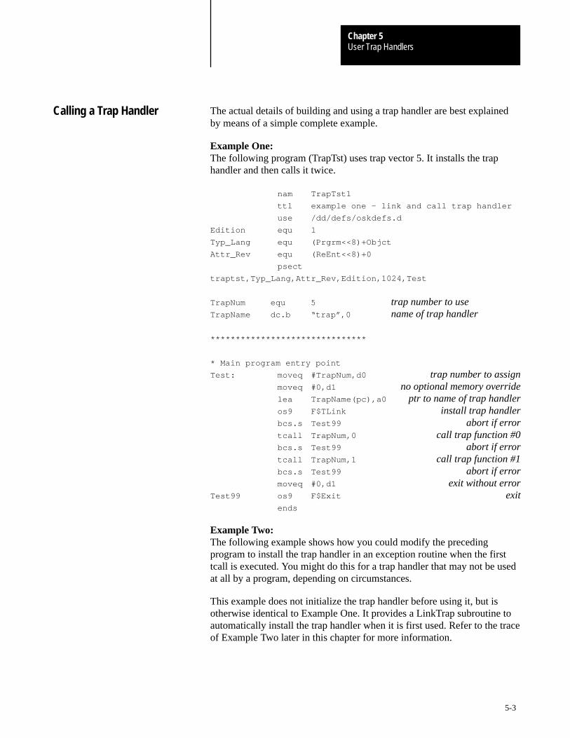
User Trap HandlersChapter 5
5-3
The actual details of building and using a trap handler are best explainedby means of a simple complete example.
Example One:The following program (TrapTst) uses trap vector 5. It installs the traphandler and then calls it twice.
nam TrapTst1
ttl example one – link and call trap handler
use /dd/defs/oskdefs.d
Edition equ 1
Typ_Lang equ (Prgrm<<8)+Objct
Attr_Rev equ (ReEnt<<8)+0
psect
traptst,Typ_Lang,Attr_Rev,Edition,1024,Test
TrapNum equ 5 trap number to useTrapName dc.b “trap”,0 name of trap handler
*******************************
* Main program entry point
Test: moveq #TrapNum,d0 trap number to assignmoveq #0,d1 no optional memory overridelea TrapName(pc),a0 ptr to name of trap handleros9 F$TLink install trap handlerbcs.s Test99 abort if errortcall TrapNum,0 call trap function #0bcs.s Test99 abort if errortcall TrapNum,1 call trap function #1bcs.s Test99 abort if errormoveq #0,d1 exit without error
Test99 os9 F$Exit exitends
Example Two:The following example shows how you could modify the precedingprogram to install the trap handler in an exception routine when the firsttcall is executed. You might do this for a trap handler that may not be usedat all by a program, depending on circumstances.
This example does not initialize the trap handler before using it, but isotherwise identical to Example One. It provides a LinkTrap subroutine toautomatically install the trap handler when it is first used. Refer to the traceof Example Two later in this chapter for more information.
Calling a Trap Handler
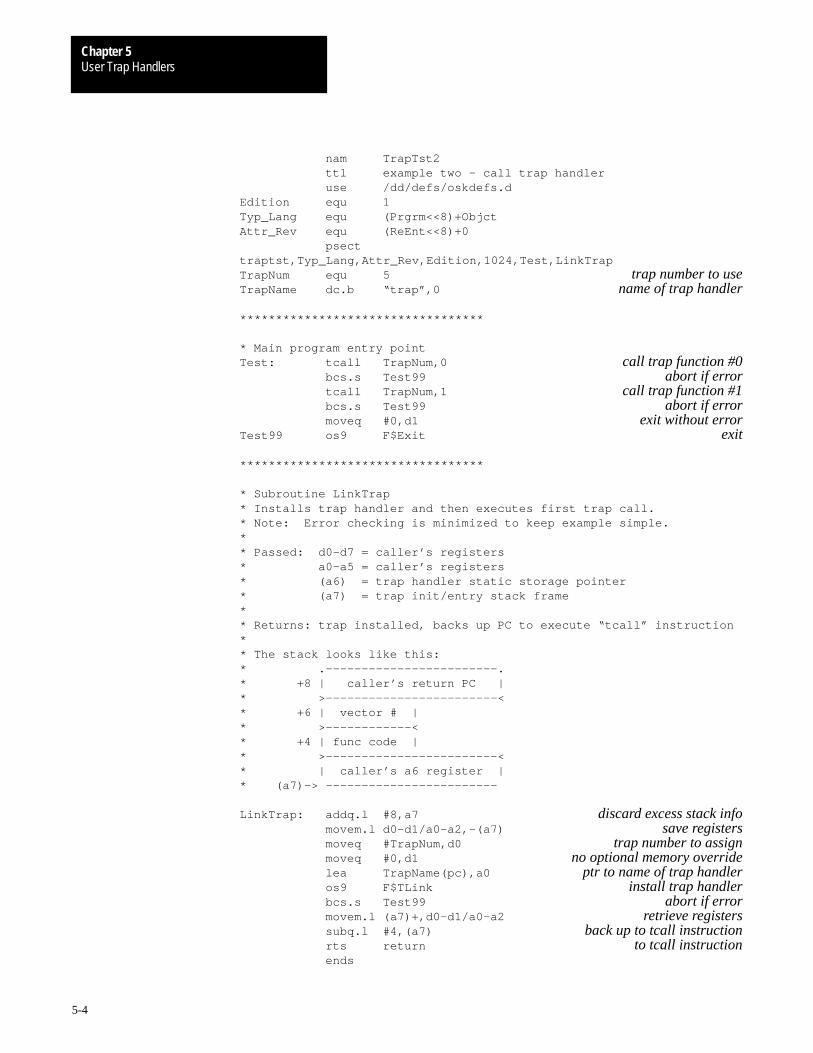
User Trap HandlersChapter 5
5-4
nam TrapTst2 ttl example two – call trap handler use /dd/defs/oskdefs.dEdition equ 1Typ_Lang equ (Prgrm<<8)+ObjctAttr_Rev equ (ReEnt<<8)+0 psecttraptst,Typ_Lang,Attr_Rev,Edition,1024,Test,LinkTrapTrapNum equ 5 trap number to useTrapName dc.b “trap”,0 name of trap handler
**********************************
* Main program entry pointTest: tcall TrapNum,0 call trap function #0 bcs.s Test99 abort if error tcall TrapNum,1 call trap function #1 bcs.s Test99 abort if error moveq #0,d1 exit without errorTest99 os9 F$Exit exit
**********************************
* Subroutine LinkTrap* Installs trap handler and then executes first trap call.* Note: Error checking is minimized to keep example simple.** Passed: d0–d7 = caller’s registers* a0–a5 = caller’s registers* (a6) = trap handler static storage pointer* (a7) = trap init/entry stack frame** Returns: trap installed, backs up PC to execute “tcall” instruction** The stack looks like this:* .––––––––––––––––––––––––.* +8 | caller’s return PC |* >––––––––––––––––––––––––<* +6 | vector # |* >––––––––––––<* +4 | func code |* >––––––––––––––––––––––––<* | caller’s a6 register |* (a7)–> ––––––––––––––––––––––––
LinkTrap: addq.l #8,a7 discard excess stack info movem.l d0–d1/a0–a2,–(a7) save registers moveq #TrapNum,d0 trap number to assign moveq #0,d1 no optional memory override lea TrapName(pc),a0 ptr to name of trap handler os9 F$TLink install trap handler bcs.s Test99 abort if error movem.l (a7)+,d0–d1/a0–a2 retrieve registers subq.l #4,(a7) back up to tcall instruction rts return to tcall instruction ends
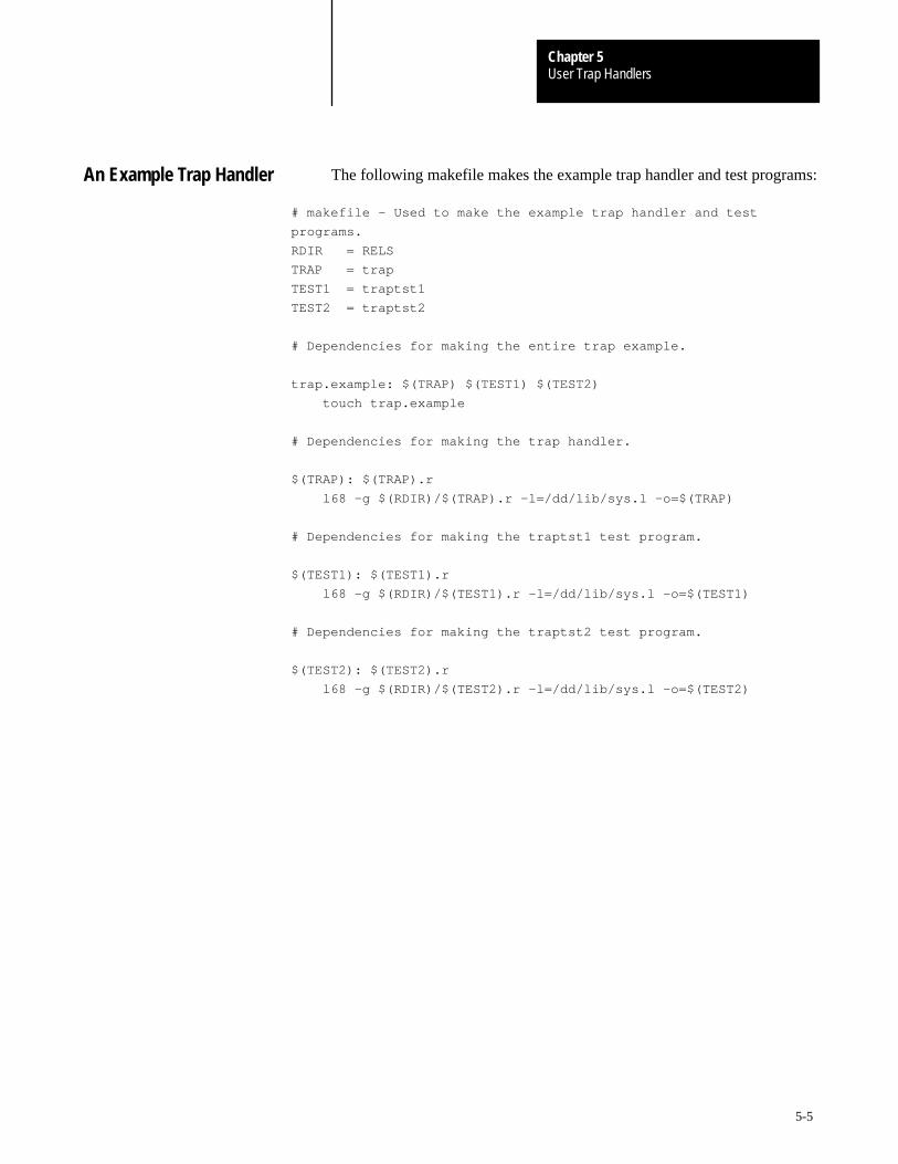
User Trap HandlersChapter 5
5-5
The following makefile makes the example trap handler and test programs:
# makefile – Used to make the example trap handler and test
programs.
RDIR = RELS
TRAP = trap
TEST1 = traptst1
TEST2 = traptst2
# Dependencies for making the entire trap example.
trap.example: $(TRAP) $(TEST1) $(TEST2)
touch trap.example
# Dependencies for making the trap handler.
$(TRAP): $(TRAP).r
l68 –g $(RDIR)/$(TRAP).r –l=/dd/lib/sys.l –o=$(TRAP)
# Dependencies for making the traptst1 test program.
$(TEST1): $(TEST1).r
l68 –g $(RDIR)/$(TEST1).r –l=/dd/lib/sys.l –o=$(TEST1)
# Dependencies for making the traptst2 test program.
$(TEST2): $(TEST2).r
l68 –g $(RDIR)/$(TEST2).r –l=/dd/lib/sys.l –o=$(TEST2)
An Example Trap Handler
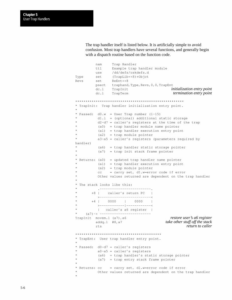
User Trap HandlersChapter 5
5-6
The trap handler itself is listed below. It is artificially simple to avoidconfusion. Most trap handlers have several functions, and generally beginwith a dispatch routine based on the function code.
nam Trap Handler ttl Example trap handler module use /dd/defs/oskdefs.dType set (TrapLib<<8)+ObjctRevs set ReEnt<<8 psect traphand,Type,Revs,0,0,TrapEnt dc.l TrapInit initialization entry point dc.l TrapTerm termination entry point
****************************************************** TrapInit: Trap handler initialization entry point.** Passed: d0.w = User Trap number (1–15)* d1.l = (optional) additional static storage* d2–d7 = caller’s registers at the time of the trap* (a0) = trap handler module name pointer* (a1) = trap handler execution entry point* (a2) = trap module pointer* a3–a5 = caller’s registers (parameters required byhandler)* (a6) = trap handler static storage pointer* (a7) = trap init stack frame pointer** Returns: (a0) = updated trap handler name pointer* (a1) = trap handler execution entry point* (a2) = trap module pointer* cc = carry set, d1.w=error code if error* Other values returned are dependent on the trap handler** The stack looks like this:* .–––––––––––––––––––––––––.* +8 | caller’s return PC |* >–––––––––––––––––––––––––<* +4 | 0000 | 0000 |* >––––––––––––|––––––––––––<* | caller’s a6 register |* (a7)–> –––––––––––––––––––––––––TrapInit movem.l (a7),a6 restore user’s a6 register addq.l #8,a7 take other stuff off the stack rts return to caller
******************************************* TrapEnt: User trap handler entry point.** Passed: d0–d7 = caller’s registers* a0–a5 = caller’s registers* (a6) = trap handler’s static storage pointer* (a7) = trap entry stack frame pointer** Returns: cc = carry set, d1.w=error code if error* Other values returned are dependent on the trap handler*
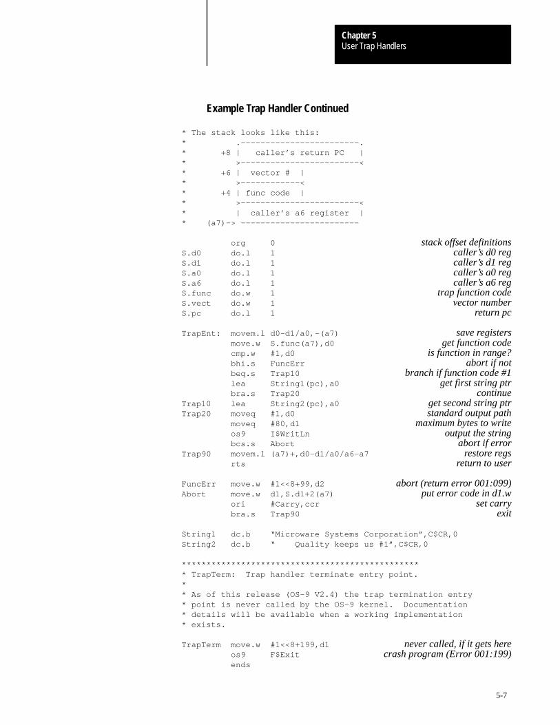
User Trap HandlersChapter 5
5-7
Example Trap Handler Continued
* The stack looks like this:* .––––––––––––––––––––––––.* +8 | caller’s return PC |* >––––––––––––––––––––––––<* +6 | vector # |* >––––––––––––<* +4 | func code |* >––––––––––––––––––––––––<* | caller’s a6 register |* (a7)–> ––––––––––––––––––––––––
org 0 stack offset definitionsS.d0 do.l 1 caller’s d0 regS.d1 do.l 1 caller’s d1 regS.a0 do.l 1 caller’s a0 regS.a6 do.l 1 caller’s a6 regS.func do.w 1 trap function codeS.vect do.w 1 vector numberS.pc do.l 1 return pc
TrapEnt: movem.l d0–d1/a0,–(a7) save registers move.w S.func(a7),d0 get function code cmp.w #1,d0 is function in range? bhi.s FuncErr abort if not beq.s Trap10 branch if function code #1 lea String1(pc),a0 get first string ptr bra.s Trap20 continueTrap10 lea String2(pc),a0 get second string ptrTrap20 moveq #1,d0 standard output path moveq #80,d1 maximum bytes to write os9 I$WritLn output the string bcs.s Abort abort if errorTrap90 movem.l (a7)+,d0–d1/a0/a6–a7 restore regs rts return to user
FuncErr move.w #1<<8+99,d2 abort (return error 001:099)Abort move.w d1,S.d1+2(a7) put error code in d1.w ori #Carry,ccr set carry bra.s Trap90 exit
String1 dc.b “Microware Systems Corporation”,C$CR,0String2 dc.b “ Quality keeps us #1”,C$CR,0
************************************************* TrapTerm: Trap handler terminate entry point.** As of this release (OS–9 V2.4) the trap termination entry* point is never called by the OS–9 kernel. Documentation* details will be available when a working implementation* exists.
TrapTerm move.w #1<<8+199,d1 never called, if it gets here os9 F$Exit crash program (Error 001:199) ends

User Trap HandlersChapter 5
5-8
It is extremely educational to watch the OS-9 user debugger trace throughthe execution of Example Two (using the example trap handler). User traphandlers look like subroutines to the debugger, so it is possible to tracethrough them. The output should appear something like this:
(beginning of second example program)Test >4E450000 trap #5,0
Important: Because the trap handler has not been linked as in ExampleOne, control jumps to the subroutine LinkTrap:
LinkTrap >508F addq.l #8,a7LinkTrap+0x2 >48E7C0E0 movem.l d0–d1/a0–a2,–(a7)LinkTrap+0x6 >7005 moveq.l #5,d0LinkTrap+0x8 >7200 moveq.l #0,d1LinkTrap+0xA >41FAFFDC lea.l bname+0xA(pc),a0LinkTrap+0xE >4E400021 os9 F$TLink
Important: Control switches to the subroutine TrapInit and then returns toLinkTrap:
trap:btext+0x50 >4CD74000 movem.l (a7),a6trap:btext+0x54 >508F addq.l #8,a7trap:btext+0x56 >4E75 rtsLinkTrap+0x12 >65E8 bcs.b Test+0xELinkTrap+0x14 >4CDF0703 movem.l (a7)+,d0–d1/a0–a2LinkTrap+0x18 >5997 subq.l #4,(a7)LinkTrap+0x1A >4E75 rts
Trace of Example Two Usingthe Example Trap Handler

User Trap HandlersChapter 5
5-9
Important: Control now returns to the main program to re-execute thetcall instruction.
Test >4E450000 trap #5,0trap:TrapEnt >48E7C080 movem.l d0–d1/a0,–(a7)trap:TrapEnt+0x4 >302F0010 move.w 16(a7),d0trap:TrapEnt+0x8 >B07C0001 cmp.w #1,d0trap:TrapEnt+0xC >621C bhi.b trap:TrapEnt+0x2Atrap:TrapEnt+0xE >6706 beq.b trap:TrapEnt+0x16trap:TrapEnt+0x10 >41FA0026 lea.l trap:TrapEnt+0x38(pc),a0trap:TrapEnt+0x14 >6004 bra.b trap:TrapEnt+0x1Atrap:TrapEnt+0x1A >7001 moveq.l #1,d0trap:TrapEnt+0x1C >7250 moveq.l #80,d1trap:TrapEnt+0x1E >4E40008C os9 I$WritLnMicroware Systems Corporationtrap:TrapEnt+0x22 >650A bcs.b trap:TrapEnt+0x2Etrap:TrapEnt+0x24 >4CDFC103 movem.l (a7)+,d0–d1/a0/a6–a7trap:TrapEnt+0x28 >4E75 rtsTest+0x4 >6508 bcs.b Test+0xETest+0x6 >4E450001 trap #5,0x1
trap:TrapEnt >48E7C080 movem.l d0–d1/a0,–(a7)trap:TrapEnt+0x4 >302F0010 move.w 16(a7),d0trap:TrapEnt+0x8 >B07C0001 cmp.w #1,d0trap:TrapEnt+0xC >621C bhi.b trap:TrapEnt+0x2Atrap:TrapEnt+0xE >6706 beq.b trap:TrapEnt+0x16–>trap:TrapEnt+0x16 >41FA003F lea.l trap:TrapEnt+0x57(pc),a0trap:TrapEnt+0x1A >7001 moveq.l #1,d0trap:TrapEnt+0x1C >7250 moveq.l #80,d1trap:TrapEnt+0x1E >4E40008C os9 I$WritLn Quality keeps us #1trap:TrapEnt+0x22 >650A bcs.b trap:TrapEnt+0x2Etrap:TrapEnt+0x24 >4CDFC103 movem.l (a7)+,d0–d1/a0/a6–a7trap:TrapEnt+0x28 >4E75 rtsTest+0xA >6502 bcs.b Test+0xETest+0xC >7200 moveq.l #0,d1Test+0xE >4E400006 os9 F$Exit

Chapter
6
6-1
The Math Module
OS-9 contains a standard function library math module which providescommon subroutines for extended mathematical and I/O conversionfunctions. OS-9 C, Basic09, and Fortran compilers also use this module.
OS-9 math modules provide the following functions:
basic floating point math extended integer math type conversion transcendental and extended mathematical functions
Normally, the math module uses software routines located in a library fileto provide the extended functions. User programs can call the librarydirectly, using the 68000 trap instruction. You can also use these libraryfiles for non-OS-9 target systems. The following are library files that canbe embedded in your applications:
Library File Use on:
Math.l Systems without a math co-processor.
Math881.I Systems with a math co-processor.
Systems that do not use a math co-processor can use the Math.l library file.In systems that do have a math co-processer, you can replace thesoftware-based files with files that use arithmetic processing hardware,without altering the application software. For example, use the Math881file for the 68881/882 FPCP.
If you do not want the math module functions embedded within yourapplication program, you can install the appropriate module as a user traproutine, and call it using the 68000 trap instruction.
Module name: File name: Trap# Use on:
Math Math 15 Systems without a math co-processor.
Math Math881 15 Systems with a math co-processor.
The Standard FunctionLibrary Module

The Math ModuleChapter 6
6-2
You can use the OS-9 Load command to pre-load the standard functionlibrary module in memory for quick access when needed. You can make itpart of the system’s startup file. Including the trap handlers in theOS9Boot file is not recommended. The following description of standardfunction module linkage and calling methods is intended for assemblylanguage programmers. Programs generated by the OS-9 compilersautomatically perform all required functions without any special action onthe part of the user.
Prior to calling the standard function modules, an assembly languageprogram should use the OS-9 F$TLink system call. The TLink parametersshould be the trap number and module name (refer to the table on theprevious page). This installs and links the user’s process to the desiredmodule(s). Calls to individual routines are made using the trap instruction.For example, a call to the FAdd function could look like this:
trap #T$Math Trap number of module
dc.w T$FAdd Code of FAdd function
For simplicity, a macro is included in the assembler for this purpose. Thefollowing line is equivalent to the above example:
tcall T$Math,T$FAdd Trap number and code for FAdd
In non-OS-9 target environments, you may also call these routines directlyusing bsr instructions, and including the appropriate library in the code(math.l). For example:
bsr _T$FAdd Floating point addition
Many functions set the MPU status register N, Z, V, and C bits so the trapor bsr may be immediately followed by a conditional branch instruction forcomparisons and error checking. When an error occurs, the system-wideconvention is followed, where the C condition code bit is set and registerd1 returns the specific error code.
In some cases a trapv instruction executes at the end of a function. Thiscauses a trapv exception if the V (overflow) condition code is set.
Some functions support two integer types:
unsigned 32-bit unsigned integers
long 32-bit signed integers
Calling Standard FunctionModule Routines
Data Formats
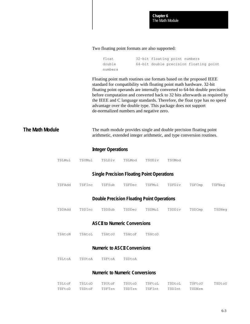
The Math ModuleChapter 6
6-3
Two floating point formats are also supported:
float 32-bit floating point numbers
double 64-bit double precision floating point
numbers
Floating point math routines use formats based on the proposed IEEEstandard for compatibility with floating point math hardware. 32-bitfloating point operands are internally converted to 64-bit double precisionbefore computation and converted back to 32 bits afterwards as required bythe IEEE and C language standards. Therefore, the float type has no speedadvantage over the double type. This package does not supportde-normalized numbers and negative zero.
The math module provides single and double precision floating pointarithmetic, extended integer arithmetic, and type conversion routines.
Integer Operations
T$LMul T$UMul T$LDiv T$LMod T$UDiv T$UMod
Single Precision Floating Point Operations
T$FAdd T$FInc T$FSub T$FDec T$FMul T$FDiv T$FCmp T$FNeg
Double Precision Floating Point Operations
T$DAdd T$DInc T$DSub T$DDec T$DMul T$DDiv T$DCmp T$DNeg
ASCII to Numeric Conversions
T$AtoN T$AtoL T$AtoU T$AtoF T$AtoD
Numeric to ASCII Conversions
T$LtoA T$UtoA T$FtoA T$DtoA
Numeric to Numeric Conversions
T$LtoF T$LtoD T$UtoF T$UtoD T$FtoL T$DtoL T$FtoU T$DtoU
T$FtoD T$DtoF T$FTrn T$DTrn T$FInt T$DInt T$DNrm
The Math Module
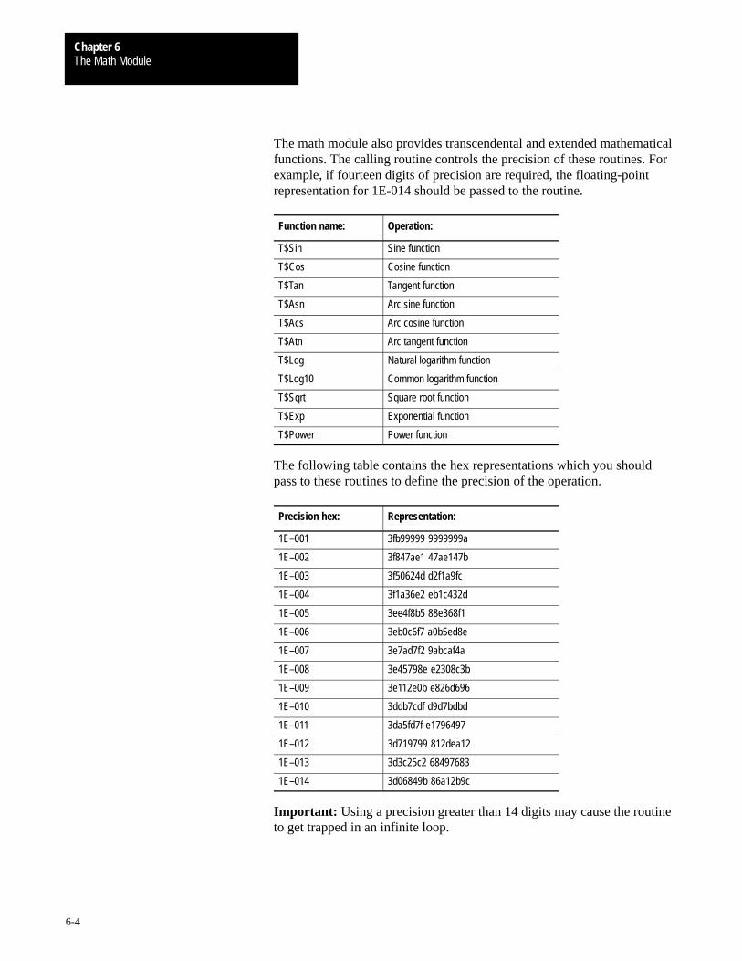
The Math ModuleChapter 6
6-4
The math module also provides transcendental and extended mathematicalfunctions. The calling routine controls the precision of these routines. Forexample, if fourteen digits of precision are required, the floating-pointrepresentation for 1E-014 should be passed to the routine.
Function name: Operation:
T$Sin Sine function
T$Cos Cosine function
T$Tan Tangent function
T$Asn Arc sine function
T$Acs Arc cosine function
T$Atn Arc tangent function
T$Log Natural logarithm function
T$Log10 Common logarithm function
T$Sqrt Square root function
T$Exp Exponential function
T$Power Power function
The following table contains the hex representations which you shouldpass to these routines to define the precision of the operation.
Precision hex: Representation:
1E–001 3fb99999 9999999a
1E–002 3f847ae1 47ae147b
1E–003 3f50624d d2f1a9fc
1E–004 3f1a36e2 eb1c432d
1E–005 3ee4f8b5 88e368f1
1E–006 3eb0c6f7 a0b5ed8e
1E–007 3e7ad7f2 9abcaf4a
1E–008 3e45798e e2308c3b
1E–009 3e112e0b e826d696
1E–010 3ddb7cdf d9d7bdbd
1E–011 3da5fd7f e1796497
1E–012 3d719799 812dea12
1E–013 3d3c25c2 68497683
1E–014 3d06849b 86a12b9c
Important: Using a precision greater than 14 digits may cause the routineto get trapped in an infinite loop.

The Math ModuleChapter 6
6-5
Arc Cosine Function
ASM Call
TCALL T$Math,T$Acs
Input
d0:d1 = x
d2:d3 = Precision
Output
d0:d1 = ArcCos(x) (in radians)
Condition Codes
C Set on error
Possible Errors
E$IllArg
Function
T$Acs returns the arc cosine() in radians. If the operand passed is illegal, anerror is returned.
T$Acs

The Math ModuleChapter 6
6-6
Arcsine Function
ASM Call
TCALL T$Math,T$Asn
Input
d0:d1 = x
d2:d3 = Precision
Output
d0:d1 = ArcSin(x) (in radians)
Condition Codes
C Set on error
Possible Errors
E$IllArg
Function
T$Asn returns the arcsine() in radians. If the operand passed is illegal, anerror is returned.
T$Asn
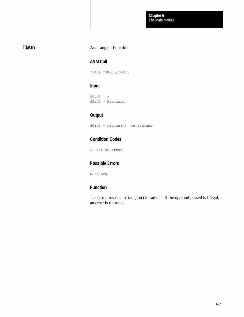
The Math ModuleChapter 6
6-7
Arc Tangent Function
ASM Call
TCALL T$Math,T$Atn
Input
d0:d1 = x
d2:d3 = Precision
Output
d0:d1 = ArcTan(x) (in radians)
Condition Codes
C Set on error
Possible Errors
E$IllArg
Function
T$Atn returns the arc tangent() in radians. If the operand passed is illegal,an error is returned.
T$Atn
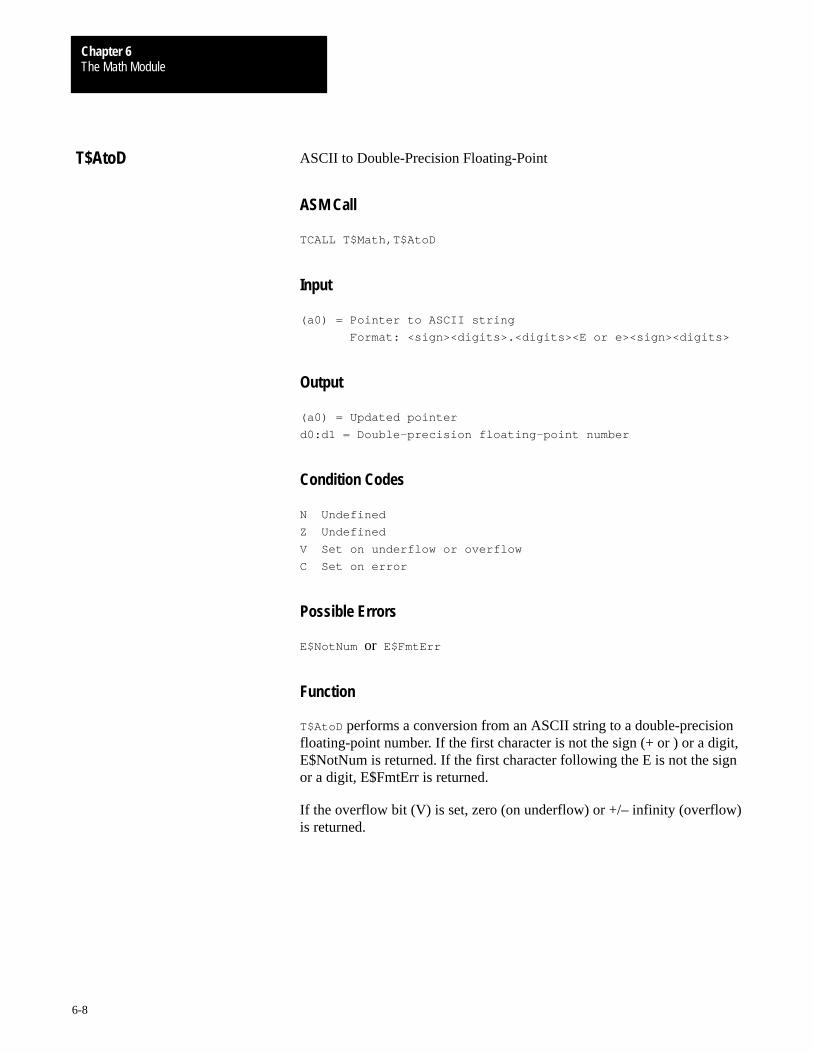
The Math ModuleChapter 6
6-8
ASCII to Double-Precision Floating-Point
ASM Call
TCALL T$Math,T$AtoD
Input
(a0) = Pointer to ASCII string
Format: <sign><digits>.<digits><E or e><sign><digits>
Output
(a0) = Updated pointer
d0:d1 = Double-precision floating-point number
Condition Codes
N Undefined
Z Undefined
V Set on underflow or overflow
C Set on error
Possible Errors
E$NotNum or E$FmtErr
Function
T$AtoD performs a conversion from an ASCII string to a double-precisionfloating-point number. If the first character is not the sign (+ or ) or a digit,E$NotNum is returned. If the first character following the E is not the signor a digit, E$FmtErr is returned.
If the overflow bit (V) is set, zero (on underflow) or +/– infinity (overflow)is returned.
T$AtoD

The Math ModuleChapter 6
6-9
ASCII to Single-Precision Floating-Point
ASM Call
TCALL T$Math,T$AtoF
Input
(a0) = Pointer to ASCII string
Format: <sign><digits>.<digits><E or e><sign><digits>
Output
(a0) = Updated pointer
d0:d1 = Double-precision floating-point number
Condition Codes
N Undefined
Z Undefined
V Set on underflow or overflow
C Set on error
Possible Errors
E$NotNum or E$FmtErr
Function
T$AtoF performs a conversion from an ASCII string to a single-precisionfloating-point number. If the first character is not the sign (+ or –) or adigit, E$NotNum is returned. If the first character following the E is notthe sign or a digit, E$FmtErr is returned.
If the overflow bit (V) is set, zero (on underflow) or +/– infinity (overflow)is returned.
T$AtoF

The Math ModuleChapter 6
6-10
ASCII to Long Conversion
ASM Call
TCALL T$Math,T$AtoL
Input
(a0) = Pointer to ASCII string (format: <sign><digits> )
Output
(a0) = Updated pointer
d0.l = Signed long
Condition Codes
N Undefined
Z Undefined
V Set on overflow
C Set on error
Possible Errors
E$NotNum
Function
T$AtoL performs a conversion from an ASCII string to a signed longinteger. If the first character is not a sign (+ or –) or a digit, an erroris returned.
T$AtoL
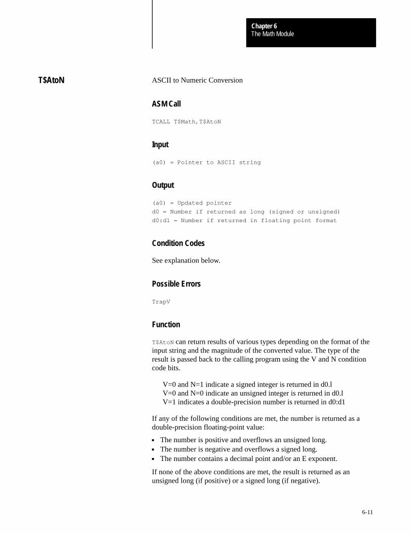
The Math ModuleChapter 6
6-11
ASCII to Numeric Conversion
ASM Call
TCALL T$Math,T$AtoN
Input
(a0) = Pointer to ASCII string
Output
(a0) = Updated pointer
d0 = Number if returned as long (signed or unsigned)
d0:d1 = Number if returned in floating point format
Condition Codes
See explanation below.
Possible Errors
TrapV
Function
T$AtoN can return results of various types depending on the format of theinput string and the magnitude of the converted value. The type of theresult is passed back to the calling program using the V and N conditioncode bits.
V=0 and N=1 indicate a signed integer is returned in d0.lV=0 and N=0 indicate an unsigned integer is returned in d0.lV=1 indicates a double-precision number is returned in d0:d1
If any of the following conditions are met, the number is returned as adouble-precision floating-point value:
The number is positive and overflows an unsigned long. The number is negative and overflows a signed long. The number contains a decimal point and/or an E exponent.
If none of the above conditions are met, the result is returned as anunsigned long (if positive) or a signed long (if negative).
T$AtoN

The Math ModuleChapter 6
6-12
ASCII to Unsigned Conversion
ASM Call
TCALL T$Math,T$AtoU
Input
(a0) = Pointer to ASCII string (format: <digits >)
Output
(a0) = Updated pointer
d0.l = Unsigned long
Condition Codes
N Undefined
Z Undefined
V Set on overflow
C Set on error
Possible Errors
E$NotNum
Function
T$AtoU performs a conversion from an ASCII string to an unsigned longinteger. If the first character is not a digit, an error is returned.
T$AtoU

The Math ModuleChapter 6
6-13
Cosine Function
ASM Call
TCALL T$Math,T$Cos
Input
d0:d1 = x (in radians)
d2:d3 = Precision
Output
d0:d1 = Cos(x)
Condition Codes
C Always clear
Possible Errors
None
Function
T$Cos returns the cosine() of an angle. The angle must be specified inradians. No errors are possible, and all condition codes are undefined.
T$Cos

The Math ModuleChapter 6
6-14
Double Precision Addition
ASM Call
TCALL T$Math,T$DAdd
Input
d0:d1 = Addend
d2:d3 = Augend
Output
d0:d1 = Result ( d0:d1 + d2:d3 )
Condition Codes
N Set if result is negative
Z Set if result is zero
V Set on underflow or overflow
C Always cleared
Possible Errors
TrapV
Function
T$DAdd adds two double-precision floating point numbers. Overflow andunderflow are indicated by setting the V bit. In either case, a trapvexception is generated. If an underflow caused the exception, zero isreturned. If it was an overflow, infinity (with the proper sign) is returned.
T$DAdd

The Math ModuleChapter 6
6-15
Double Precision Compare
ASM Call
TCALL T$Math,T$DCmp
Input
d0:d1 = First operand
d2:d3 = Second operand
Output
d0.l through d3.l remain unchanged
Condition Codes
N Set if second operand is larger than the first
Z Set if operands are equal
V Always cleared
C Always cleared
Possible Errors
None
Function
Two double-precision floating point numbers are compared by T$DCmp.The operands passed to this function are not destroyed.
T$DCmp

The Math ModuleChapter 6
6-16
Double Precision Decrement
ASM Call
TCALL T$Math,T$DDec
Input
d0:d1 = Operand
Output
d0:d1 = Result ( d0:d1 – 1.0 )
Condition Codes
N Set if result is negative
Z Set if result is zero
V Set on underflow
C Always cleared
Possible Errors
TrapV
Function
This function subtracts 1.0 from the double-precision floating pointoperand. Underflow is indicated by setting the V bit. If an underflowoccurs, a trapv exception is generated and zero is returned.
T$DDec
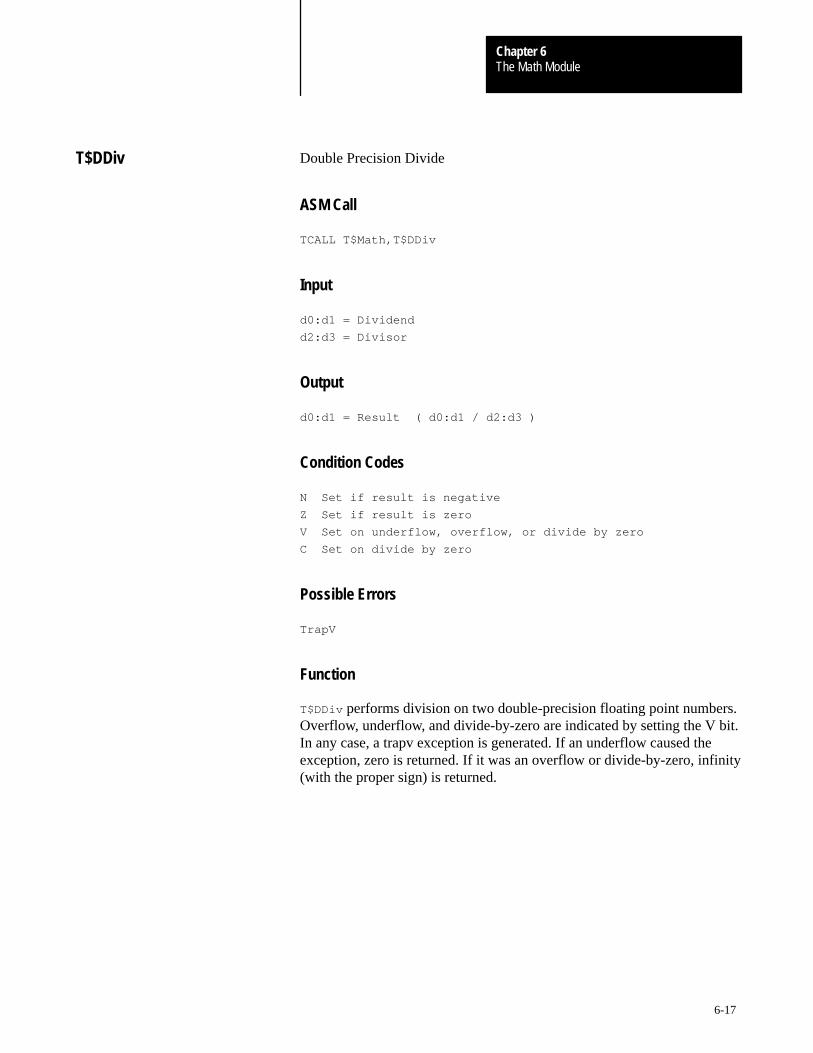
The Math ModuleChapter 6
6-17
Double Precision Divide
ASM Call
TCALL T$Math,T$DDiv
Input
d0:d1 = Dividend
d2:d3 = Divisor
Output
d0:d1 = Result ( d0:d1 / d2:d3 )
Condition Codes
N Set if result is negative
Z Set if result is zero
V Set on underflow, overflow, or divide by zero
C Set on divide by zero
Possible Errors
TrapV
Function
T$DDiv performs division on two double-precision floating point numbers.Overflow, underflow, and divide-by-zero are indicated by setting the V bit.In any case, a trapv exception is generated. If an underflow caused theexception, zero is returned. If it was an overflow or divide-by-zero, infinity(with the proper sign) is returned.
T$DDiv

The Math ModuleChapter 6
6-18
Double Precision Increment
ASM Call
TCALL T$Math,T$DInc
Input
d0:d1 = Operand
Output
d0:d1 = Result ( d0:d1 + 1.0 )
Condition Codes
N Set if result is negative
Z Set if result is zero
V Set on overflow
C Always cleared
Possible Errors
TrapV
Function
T$DInc adds 1.0 to the double-precision floating point operand. Overflowis indicated by setting the V bit. If an overflow occurs, a trapv exception isgenerated and infinity (with the proper sign) is returned.
T$DInc
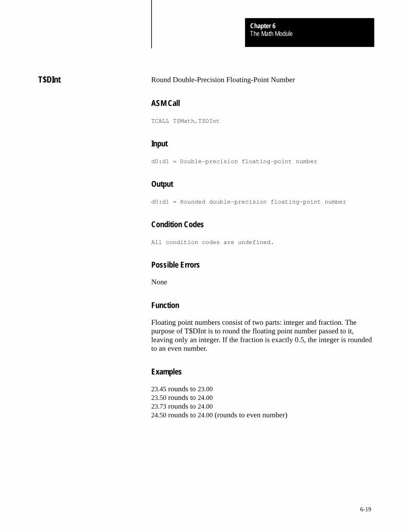
The Math ModuleChapter 6
6-19
Round Double-Precision Floating-Point Number
ASM Call
TCALL T$Math,T$DInt
Input
d0:d1 = Double-precision floating-point number
Output
d0:d1 = Rounded double-precision floating-point number
Condition Codes
All condition codes are undefined.
Possible Errors
None
Function
Floating point numbers consist of two parts: integer and fraction. Thepurpose of T$DInt is to round the floating point number passed to it,leaving only an integer. If the fraction is exactly 0.5, the integer is roundedto an even number.
Examples
23.45 rounds to 23.0023.50 rounds to 24.0023.73 rounds to 24.0024.50 rounds to 24.00 (rounds to even number)
T$DInt

The Math ModuleChapter 6
6-20
Double Precision Multiplication
ASM Call
TCALL T$Math,T$DMul
Input
d0:d1 = Multiplicand
d2:d3 = Multiplier
Output
d0:d1 = Result ( d0:d1 * d2:d3 )
Condition Codes
N Set if result is negative
Z Set if result is zero
V Set on underflow or overflow
C Always cleared
Possible Errors
TrapV
Function
T$DMul multiplies two double-precision floating point numbers. Overflowand underflow are indicated by setting the V bit. In either case, a trapvexception is generated. If an underflow caused the exception, zero isreturned. If it was an overflow, infinity (with the proper sign) is returned.
T$DMul
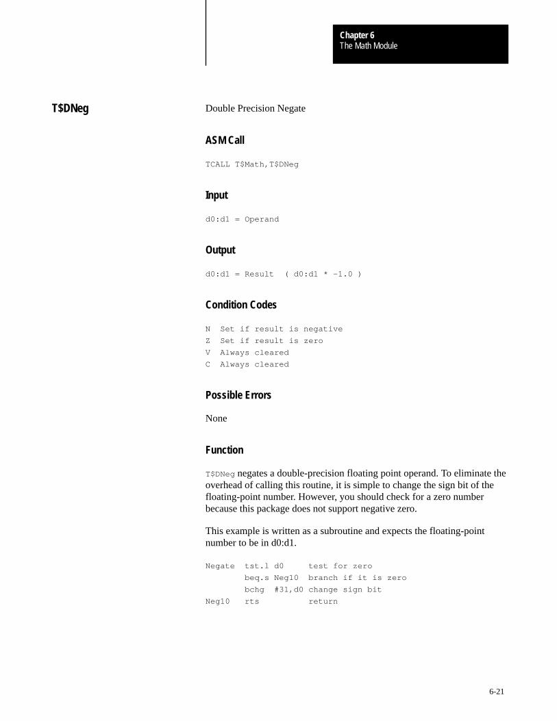
The Math ModuleChapter 6
6-21
Double Precision Negate
ASM Call
TCALL T$Math,T$DNeg
Input
d0:d1 = Operand
Output
d0:d1 = Result ( d0:d1 * –1.0 )
Condition Codes
N Set if result is negative
Z Set if result is zero
V Always cleared
C Always cleared
Possible Errors
None
Function
T$DNeg negates a double-precision floating point operand. To eliminate theoverhead of calling this routine, it is simple to change the sign bit of thefloating-point number. However, you should check for a zero numberbecause this package does not support negative zero.
This example is written as a subroutine and expects the floating-pointnumber to be in d0:d1.
Negate tst.l d0 test for zero
beq.s Neg10 branch if it is zero
bchg #31,d0 change sign bit
Neg10 rts return
T$DNeg
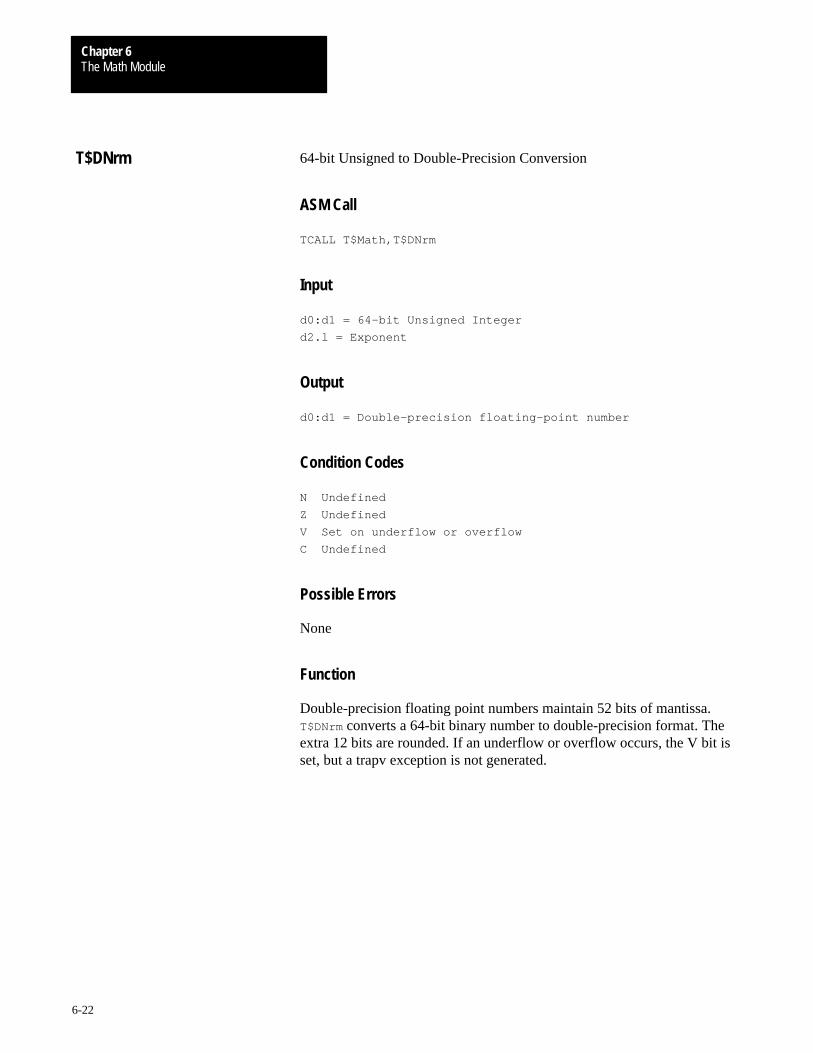
The Math ModuleChapter 6
6-22
64-bit Unsigned to Double-Precision Conversion
ASM Call
TCALL T$Math,T$DNrm
Input
d0:d1 = 64-bit Unsigned Integer
d2.l = Exponent
Output
d0:d1 = Double-precision floating-point number
Condition Codes
N Undefined
Z Undefined
V Set on underflow or overflow
C Undefined
Possible Errors
None
Function
Double-precision floating point numbers maintain 52 bits of mantissa.T$DNrm converts a 64-bit binary number to double-precision format. Theextra 12 bits are rounded. If an underflow or overflow occurs, the V bit isset, but a trapv exception is not generated.
T$DNrm

The Math ModuleChapter 6
6-23
Double-Precision Subtraction
ASM Call
TCALL T$Math,T$DSub
Input
d0:d1 = Minuend
d2:d3 = Subtrahend
Output
d0:d1 = Result ( d0:d1 – d2:d3 )
Condition Codes
N Set if result is negative
Z Set if result is zero
V Set on underflow or overflow
C Always cleared
Possible Errors
TrapV
Function
T$DSub performs subtraction on two double-precision floating pointnumbers. Overflow and underflow are indicated by setting the V bit. Ineither case, a trapv exception is generated. If an underflow caused theexception, zero is returned. If it was an overflow, infinity (with the propersign) is returned.
T$DSub
The Math ModuleChapter 6
6-24
Double-Precision Floating-Point to ASCII
ASM Call
TCALL T$Math,T$DtoA
Input
d0:d1 = Double-precision floating-point number
d2.l = Low-Word: digits desired in result
High-Word: digits desired after decimal-point
(a0) = Pointer to conversion buffer
Output
(a0) = ASCII digit string
d0.l = Two’s complement exponent
Condition Codes
N Set if the number is negative
Z Undefined
V Undefined
C Undefined
Possible Errors
None
Function
The double-precision float passed to T$DtoA is converted to an ASCIIstring. The conversion terminates as soon as the number of digits requestedare converted, or when the specified digit after the decimal point isreached; whichever comes first. A null is appended to the end of the string.Therefore, the buffer should be one byte larger than the expected numberof digits.
The converted string only contains the mantissa digits. The N bit indicatesthe sign of the number, and the exponent returns in register d0.
T$DtoA

The Math ModuleChapter 6
6-25
Double to Single Floating-Point Conversion
ASM Call
TCALL T$Math,T$DtoF
Input
d0:d1 = Double-precision floating-point number
Output
d0.l = Single-precision floating-point number
Condition Codes
N Undefined
Z Undefined
V Set on underflow or overflow
C Undefined
Possible Errors
TrapV
Function
T$DtoF converts floating-point numbers in double-precision format tosingle-precision format. No errors are possible and all condition codes areundefined. If an overflow or underflow occurs, the V bit is set and a trapvexception is generated.
T$DtoF
The Math ModuleChapter 6
6-26
Double-Precision to Signed Long Integer
ASM Call
TCALL T$Math,T$DtoL
Input
d0:d1 = Double-precision floating-point number
Output
d0.l = Signed Long Integer
Condition Codes
N Undefined
Z Undefined
V Set on overflow
C Undefined
Possible Errors
TrapV
Function
The integer portion of the floating point number is converted to a signedlong integer. The fraction is truncated. If an overflow occurs, the V bit isset and a trapv exception is generated.
T$DtoL
The Math ModuleChapter 6
6-27
Double-Precision to Unsigned Long Integer
ASM Call
TCALL T$Math,T$DtoU
Input
d0:d1 = Double-precision floating-point number
Output
d0.l = Unsigned Long Integer
Condition Codes
N Undefined
Z Undefined
V Set on overflow
C Undefined
Possible Errors
TrapV
Function
The integer portion of the floating point number converts to an unsignedlong integer. The fraction is truncated. If an overflow occurs, the V bit isset and a trapv exception is generated.
T$DtoU

The Math ModuleChapter 6
6-28
Truncate Double-Precision Floating-Point Number
ASM Call
TCALL T$Math,T$DTrn
Input
d0:d1 = Double-precision floating-point number
Output
d0:d1 = Normalized integer portion of the floating point
number
d2:d3 = Normalized fractional portion of the floating point
number
Condition Codes
All condition codes are undefined.
Possible Errors
None
Function
Floating point numbers consist of two parts: integer and fraction. Thepurpose of T$DTrn is to separate the two parts. For example, if the numberpassed is 283.75, this function returns 283.00 in d0:d1 and 0.75 in d2:d3.
T$DTrn

The Math ModuleChapter 6
6-29
Exponential Function
ASM Call
TCALL T$Math,T$Exp
Input
d0:d1 = x
d2:d3 = Precision
Output
d0:d1 = Exp(x)
Condition Codes
C Always clear
Possible Errors
None
Function
T$Exp performs the exponential function on the argument passed. That is,it raises e to the x power (where e = 2.718282 and x is theargument passed).
T$Exp
The Math ModuleChapter 6
6-30
Single Precision Addition
ASM Call
TCALL T$Math,T$FAdd
Input
d0.l = Addend
d0.l = Augend
Output
d0.l = Result ( d0 + d1 )
Condition Codes
N Set if result is negative
Z Set if result is zero
V Set on underflow or overflow
C Always cleared
Possible Errors
TrapV
Function
T$FAdd adds two single-precision floating point numbers. Overflow andunderflow are indicated by setting the V bit. In either case, a trapvexception is generated. If an underflow caused the exception, zero isreturned. If it was an overflow, infinity (with the proper sign) is returned.
T$FAdd

The Math ModuleChapter 6
6-31
Single Precision Compare
ASM Call
TCALL T$Math,T$FCmp
Input
d0.l = First operand
d1.l = Second operand
Output
d0.l and d1.l remain unchanged
Condition Codes
N Set if second operand is larger than the first
Z Set if operands are equal
V Always cleared
C Always cleared
Possible Errors
None
Function
Two single-precision floating point numbers are compared by T$FCmp.The operands passed to T$FCmp are not destroyed.
T$FCmp
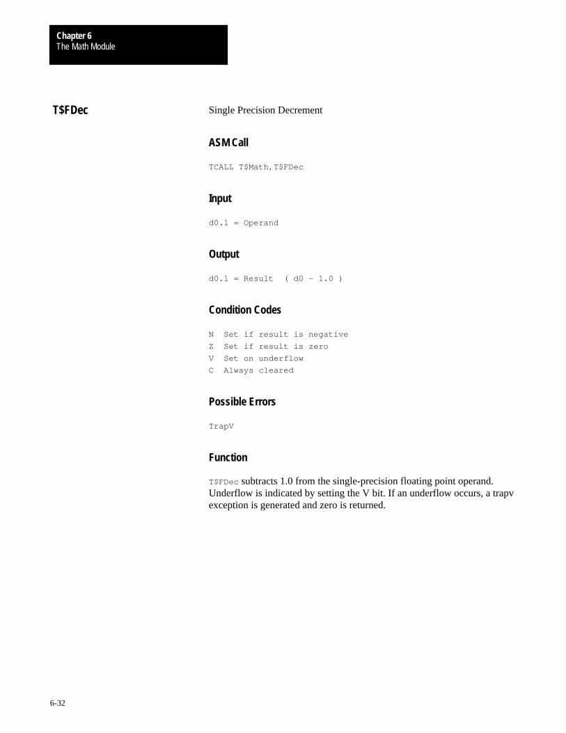
The Math ModuleChapter 6
6-32
Single Precision Decrement
ASM Call
TCALL T$Math,T$FDec
Input
d0.l = Operand
Output
d0.l = Result ( d0 – 1.0 )
Condition Codes
N Set if result is negative
Z Set if result is zero
V Set on underflow
C Always cleared
Possible Errors
TrapV
Function
T$FDec subtracts 1.0 from the single-precision floating point operand.Underflow is indicated by setting the V bit. If an underflow occurs, a trapvexception is generated and zero is returned.
T$FDec

The Math ModuleChapter 6
6-33
Single Precision Divide
ASM Call
TCALL T$Math,T$FDiv
Input
d0.l = Dividend
d1.l = Divisor
Output
d0.l = Result ( d0 / d1 )
Condition Codes
N Set if result is negative
Z Set if result is zero
V Set on underflow, overflow or divide by zero
C Set on divide by zero
Possible Errors
TrapV
Function
T$FDiv performs division on two single-precision floating point numbers.Overflow, underflow, and divide-by-zero are indicated by setting the V bit.In any case, a trapv exception is generated. If an underflow caused theexception, zero is returned. If it was an overflow or divide-by-zero, infinity(with the proper sign) is returned.
T$FDiv

The Math ModuleChapter 6
6-34
Single Precision Increment
ASM Call
TCALL T$Math,T$FInc
Input
d0.l = Operand
Output
d0.l = Result ( d0 + 1.0 )
Condition Codes
N Set if result is negative
Z Set if result is zero
V Set on overflow
C Always cleared
Possible Errors
TrapV
Function
T$FInc adds 1.0 to the single-precision floating point operand. Overflow isindicated by setting the V bit. If an overflow occurs, a trapv exception isgenerated and infinity (with the proper sign) is returned.
T$FInc

The Math ModuleChapter 6
6-35
Round Single-Precision Floating-Point Number
ASM Call
TCALL T$Math,T$FInt
Input
d0.l = Single-precision floating-point number
Output
d0.l = Rounded single-precision floating-point number
Condition Codes
All condition codes are undefined.
Possible Errors
None
Function
Floating point numbers consist of two parts: integer and fraction. Thepurpose of T$FInt is to round the floating point number passed to it,leaving only an integer. If the fraction is exactly 0.5, the integer is roundedto an even number.
Examples
23.45 rounds to 23.0023.50 rounds to 24.0023.73 rounds to 24.0024.50 rounds to 24.00 (rounds to even number)
T$FInt

The Math ModuleChapter 6
6-36
Single Precision Multiplication
ASM Call
TCALL T$Math,T$FMul
Input
d0.l = Multiplicand
d1.l = Multiplier
Output
d0.l = Result ( d0 * d1 )
Condition Codes
N Set if result is negative
Z Set if result is zero
V Set on underflow or overflow
C Always cleared
Possible Errors
TrapV
Function
T$FMul multiplies two single-precision floating point numbers. Overflowand underflow are indicated by setting the V bit. In either case, a trapvexception is generated. If an underflow caused the exception, zero isreturned. If it was an overflow, infinity (with the proper sign) is returned.
T$FMul

The Math ModuleChapter 6
6-37
Single Precision Negate
ASM Call
TCALL T$Math,T$FNeg
Input
d0.l = Operand
Output
d0.l = Result ( d0 * –1.0 )
Condition Codes
N Set if result is negative
Z Set if result is zero
V Always cleared
C Always cleared
Possible Errors
None
Function
T$FNeg negates a single-precision floating point operand. To eliminate theoverhead of calling this routine, it is simple to change the sign bit of thefloating-point number. Be sure to check for a zero number, because thispackage does not support negative zero.
This example is written as a subroutine and expects the floating-pointnumber to be in d0.
Negate tst.l d0 test for zero
beq.s Neg10 branch if it is zero
bchg #31,d0 change sign bit
Neg10 rts return
T$FNeg

The Math ModuleChapter 6
6-38
Single Precision Subtraction
ASM Call
TCALL T$Math,T$FSub
Input
d0.l = Minuend
d1.l = Subtrahend
Output
d0.l = Result ( d0 – d1 )
Condition Codes
N Set if result is negative
Z Set if result is zero
V Set on underflow or overflow
C Always cleared
Possible Errors
TrapV
Function
T$FSub performs subtraction on two single-precision floating pointnumbers. Overflow and underflow are indicated by setting the V bit. Ineither case, a trapv exception is generated. If an underflow caused theexception, zero is returned. If it was an overflow, infinity (with the propersign) is returned.
T$FSub
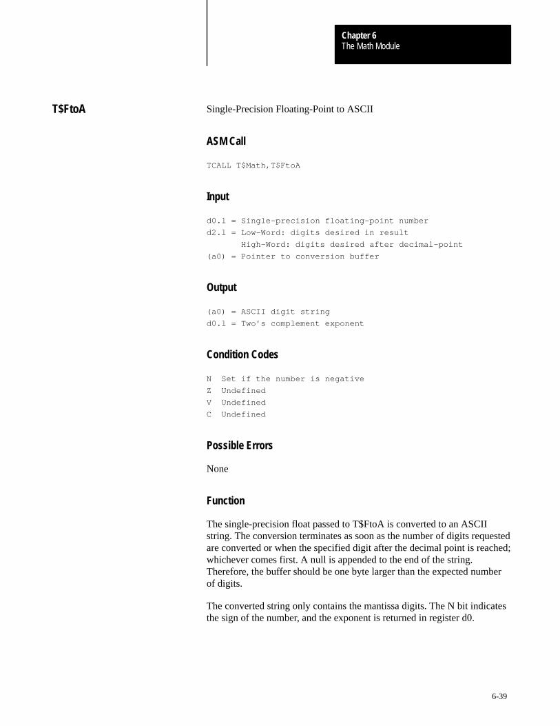
The Math ModuleChapter 6
6-39
Single-Precision Floating-Point to ASCII
ASM Call
TCALL T$Math,T$FtoA
Input
d0.l = Single-precision floating-point number
d2.l = Low-Word: digits desired in result
High-Word: digits desired after decimal-point
(a0) = Pointer to conversion buffer
Output
(a0) = ASCII digit string
d0.l = Two’s complement exponent
Condition Codes
N Set if the number is negative
Z Undefined
V Undefined
C Undefined
Possible Errors
None
Function
The single-precision float passed to T$FtoA is converted to an ASCIIstring. The conversion terminates as soon as the number of digits requestedare converted or when the specified digit after the decimal point is reached;whichever comes first. A null is appended to the end of the string.Therefore, the buffer should be one byte larger than the expected numberof digits.
The converted string only contains the mantissa digits. The N bit indicatesthe sign of the number, and the exponent is returned in register d0.
T$FtoA
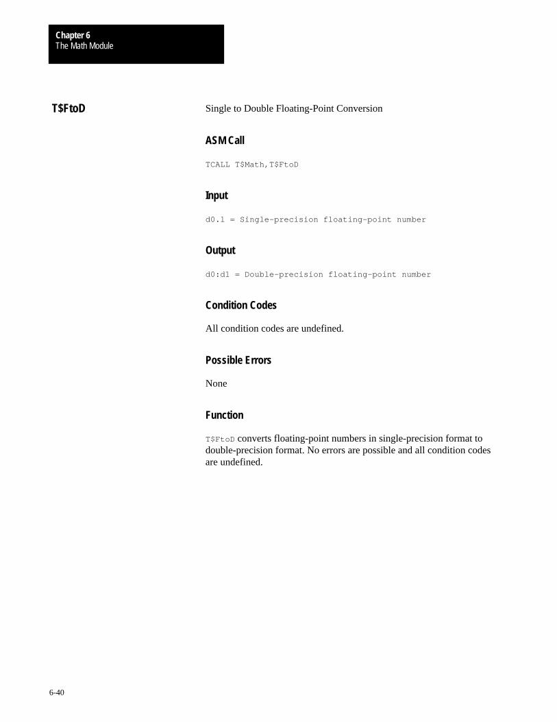
The Math ModuleChapter 6
6-40
Single to Double Floating-Point Conversion
ASM Call
TCALL T$Math,T$FtoD
Input
d0.l = Single-precision floating-point number
Output
d0:d1 = Double-precision floating-point number
Condition Codes
All condition codes are undefined.
Possible Errors
None
Function
T$FtoD converts floating-point numbers in single-precision format todouble-precision format. No errors are possible and all condition codesare undefined.
T$FtoD

The Math ModuleChapter 6
6-41
Single-Precision to Signed Long Integer
ASM Call
TCALL T$Math,T$FtoL
Input
d0.l = Single-precision floating-point number
Output
d0.l = Signed Long Integer
Condition Codes
N Undefined
Z Undefined
V Set on overflow
C Undefined
Possible Errors
TrapV
Function
T$FtoL converts the integer portion of the floating point number to asigned long integer. The fraction is truncated. If an overflow occurs, the Vbit is set and a trapv exception is generated.
T$FtoL
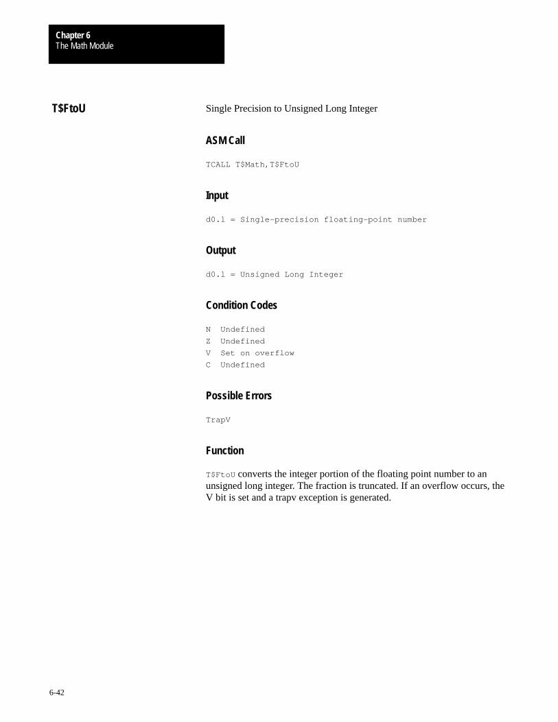
The Math ModuleChapter 6
6-42
Single Precision to Unsigned Long Integer
ASM Call
TCALL T$Math,T$FtoU
Input
d0.l = Single-precision floating-point number
Output
d0.l = Unsigned Long Integer
Condition Codes
N Undefined
Z Undefined
V Set on overflow
C Undefined
Possible Errors
TrapV
Function
T$FtoU converts the integer portion of the floating point number to anunsigned long integer. The fraction is truncated. If an overflow occurs, theV bit is set and a trapv exception is generated.
T$FtoU

The Math ModuleChapter 6
6-43
Truncate Single-Precision Floating-Point Number
ASM Call
TCALL T$Math,T$FTrn
Input
d0.l = Single-precision floating-point number
Output
d0.l = Truncated single-precision floating-point number
Condition Codes
All condition codes are undefined.
Possible Errors
None
Function
Floating point numbers consist of two parts: integer and fraction. Thepurpose of T$FTrn is to truncate the fractional part. For example, if thenumber passed is 283.75, this function returns 283.00.
T$FTrn

The Math ModuleChapter 6
6-44
Long (Signed) Divide
ASM Call
TCALL T$Math,T$LDiv
Input
d0.l = Dividend
d1.l = Divisor
Output
d0.l = Result ( d0 / d1 )
Condition Codes
N Set if result is negative
Z Set if result is zero
V Set on divide by zero
C Always cleared
Possible Errors
None
Function
T$LDiv performs 32-bit integer division. A division by zero error isindicated by setting the overflow bit. If a division by zero is attempted,infinity (with the proper sign) is returned.
Positive Infinity = $7FFFFFFFNegative Infinity = $80000000
T$LDiv

The Math ModuleChapter 6
6-45
Long (Signed) Modulus
ASM Call
TCALL T$Math,T$LMod
Input
d0.l = Dividend
d1.l = Divisor
Output
d0.l = Result ( Mod(d0/d1) )
Condition Codes
N Set if result is negative
Z Set if result is zero
V Set on divide by zero
C Always cleared
Possible Errors
None
Function
T$LMod returns the remainder (modulo) of the integer division. If anoverflow occurs, the V bit is set and zero is returned.
T$LMod

The Math ModuleChapter 6
6-46
Long (Signed) Multiply
ASM Call
TCALL T$Math,T$LMul
Input
d0.l = Multiplicand
d1.l = Multiplier
Output
d0.l = Result ( d0 * d1 )
Condition Codes
N Set if result is negative
Z Set if result is zero
V Set on overflow
C Always cleared
Possible Errors
None
Function
T$LMul performs a 32-bit signed integer multiplication. If an overflowoccurs, the V bit is set and the lower 32 bits of the result is returned. If anoverflow occurs, the sign of the result is still correct.
T$LMul
The Math ModuleChapter 6
6-47
Natural Logarithm Function
ASM Call
TCALL T$Math,T$Log
Input
d0:d1 = x
d2:d3 = Precision
Output
d0:d1 = Log(x)
Condition Codes
C Set on error
Possible Errors
E$IllArg
Function
T$Log returns the natural logarithm of the argument passed. If an illegalargument is passed, an error is returned.
T$Log

The Math ModuleChapter 6
6-48
Common Logarithm Function
ASM Call
TCALL T$Math,T$Log10
Input
d0:d1 = x
d2:d3 = Precision
Output
d0:d1 = Log10(x)
Condition Codes
C Set on error
Possible Errors
E$IllArg
Function
T$Log10 returns the common logarithm of the argument passed. If anillegal argument is passed, an error is returned.
T$Log10

The Math ModuleChapter 6
6-49
Signed Integer to ASCII Conversion
ASM Call
TCALL T$Math,T$LtoA
Input
do.1 = Signed long interger
(a0) = Pointer to conversion buffer
Output
(a0) = ASCII digit string
Condition Codes
N Set if the number is negative
Z Undefined
V Undefined
C Undefined
Possible Errors
None
Function
The signed long passed to T$LtoA is converted to an ASCII string of ten(10) digits. If the number is smaller than ten digits, it is right justified andpadded with leading zeros. A null is appended to the end of the stringmaking the minimum size of the buffer eleven (11) characters.
Important: The N bit indicates the sign and is not included in theASCII string.
T$LtoA

The Math ModuleChapter 6
6-50
Signed Long to Double-Precision Floating-Point
ASM Call
TCALL T$Math,T$LtoD
Input
d0.l = Signed long integer
Output
d0:d1 = Double-precision floating-point number
Condition Codes
All condition codes are undefined.
Possible Errors
None
Function
T$LtoD converts the signed integer to a double-precision float. No errorsare possible and all condition codes are undefined.
T$LtoD
The Math ModuleChapter 6
6-51
Signed Long to Single-Precision Floating-Point
ASM Call
TCALL T$Math,T$LtoF
Input
d0.l = Signed long integer
Output
d0.l = Single-precision floating-point number
Condition Codes
All condition codes are undefined.
Possible Errors
None
Function
T$LtoF converts the signed integer to a single-precision float. No errors arepossible and all condition codes are undefined.
T$LtoF

The Math ModuleChapter 6
6-52
Power Function
ASM Call
TCALL T$Math,T$Power
Input
d0:d1 = x
d2:d3 = y
d4:d5 = Precision
Output
d0:d1 = x^y
Condition Codes
C Set on error
Possible Errors
E$IllArg
Function
T$Power performs the power function on the arguments passed. That is, itraises x to the y power. If an illegal argument is passed, an erroris returned.
T$Power

The Math ModuleChapter 6
6-53
Tangent Function
ASM Call
TCALL T$Math,T$Sin
Input
d0:d1 = x (in radians)
d2:d3 = Precision
Output
d0:d1 = Sin(x)
Condition Codes
C Always clear
Possible Errors
None
Function
T$Sin returns the sine() of an angle. The angle must be specified inradians. No errors are possible, and all condition codes are undefined.
T$Sin
The Math ModuleChapter 6
6-54
Square Root Function
ASM Call
TCALL T$Math,T$Sqrt
Input
d0:d1 = x
d2:d3 = Precision
Output
d0:d1 = Sqrt(x)
Condition Codes
C Set on error
Possible Errors
E$IllArg
Function
T$Sqrt returns the square root of the argument passed. If an illegalargument is passed an error is returned.
T$Sqrt

The Math ModuleChapter 6
6-55
Tangent Function
ASM Call
TCALL T$Math,T$Tan
Input
d0:d1 = x (in radians)
d2:d3 = Precision
Output
d0:d1 = Tan(x)
Condition Codes
C Always clear
Possible Errors
None
Function
T$Tan returns the tangent() of an angle. The angle must be specified inradians. No errors are possible, and all condition codes are undefined.
T$Tan
The Math ModuleChapter 6
6-56
Unsigned Divide
ASM Call
TCALL T$Math,T$UDiv
Input
d0.l = Dividend
d1.l = Divisor
Output
d0.l = Result ( d0 / d1 )
Condition Codes
N Undefined
Z Set if result is zero
V Set on divide by zero
C Always cleared
Possible Errors
None
Function
T$UDiv performs 32-bit unsigned integer division. The overflow bit is setwhen a division by zero error occurs. If a division by zero is attempted,infinity ($FFFFFFFF) is returned.
T$UDiv
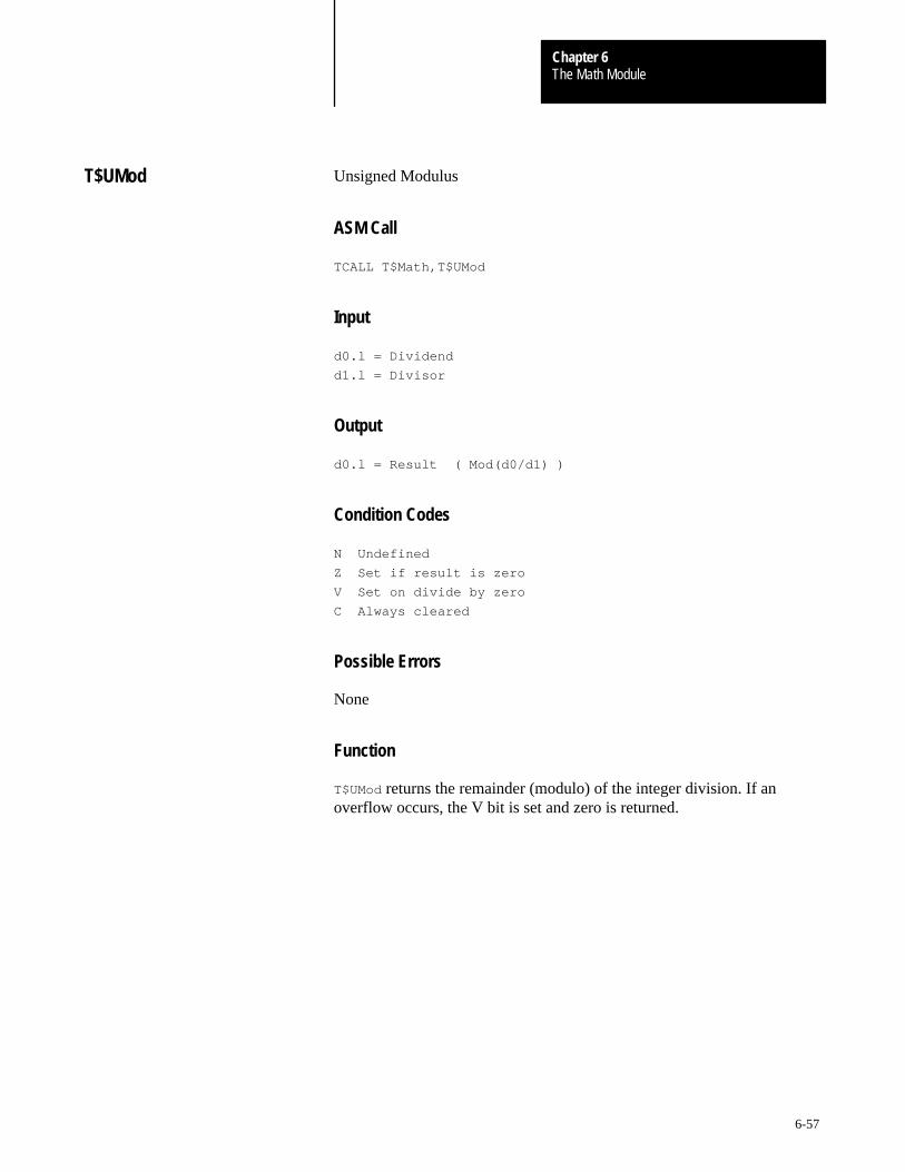
The Math ModuleChapter 6
6-57
Unsigned Modulus
ASM Call
TCALL T$Math,T$UMod
Input
d0.l = Dividend
d1.l = Divisor
Output
d0.l = Result ( Mod(d0/d1) )
Condition Codes
N Undefined
Z Set if result is zero
V Set on divide by zero
C Always cleared
Possible Errors
None
Function
T$UMod returns the remainder (modulo) of the integer division. If anoverflow occurs, the V bit is set and zero is returned.
T$UMod

The Math ModuleChapter 6
6-58
Unsigned Multiply
ASM Call
TCALL T$Math,T$UMul
Input
d0.l = Multiplicand
d1.l = Multiplier
Output
d0.l = Result ( d0 * d1 )
Condition Codes
N Undefined
Z Set if result is zero
V Set on overflow
C Always cleared
Possible Errors
None
Function
T$UMul performs a 32-bit unsigned integer multiplication. If an overflowoccurs, the V bit is set and the lower 32 bits of the result is returned.
T$UMul
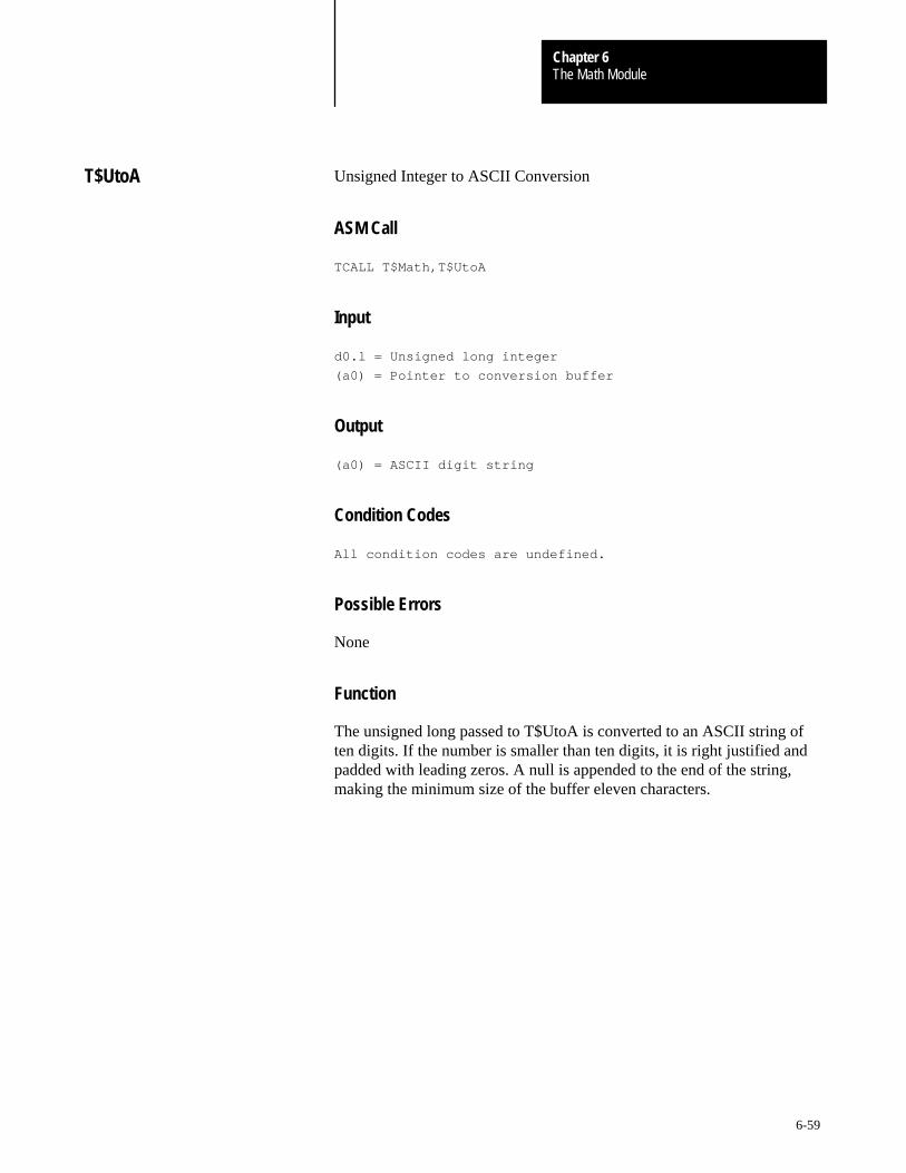
The Math ModuleChapter 6
6-59
Unsigned Integer to ASCII Conversion
ASM Call
TCALL T$Math,T$UtoA
Input
d0.l = Unsigned long integer
(a0) = Pointer to conversion buffer
Output
(a0) = ASCII digit string
Condition Codes
All condition codes are undefined.
Possible Errors
None
Function
The unsigned long passed to T$UtoA is converted to an ASCII string often digits. If the number is smaller than ten digits, it is right justified andpadded with leading zeros. A null is appended to the end of the string,making the minimum size of the buffer eleven characters.
T$UtoA

The Math ModuleChapter 6
6-60
Unsigned Long to Double-Precision Floating-Point
ASM Call
TCALL T$Math,T$UtoD
Input
d0.l = Unsigned long integer
Output
d0:d1 = Double-precision floating-point number
Condition Codes
All condition codes are undefined.
Possible Errors
None
Function
T$UtoD converts the unsigned integer to a double-precision float. No errorsare possible and all condition codes are undefined.
T$UtoD

The Math ModuleChapter 6
6-61
Unsigned Long to Single-Precision Floating-Point
ASM Call
TCALL T$Math,T$UtoF
Input
d0.l = Unsigned long integer
Output
d0.l = Single-precision floating-point number
Condition Codes
All condition codes are undefined.
Possible Errors
None
Function
T$UtoF converts the unsigned integer to a single-precision float. No errorsare possible and all condition codes are undefined.
T$UtoF

Chapter
7
7-1
OS-9 File System
RBF supports a tree-structured file system. The physical disk organizationis designed for efficient use of disk space, resistance to accidental damage,and fast file access. The system also has the advantage ofrelative simplicity.
Basic Disk Organization
RBF supports logical sector sizes in integral binary multiples from 256 to32768 bytes. If you use a disk system that cannot directly support thelogical sector size (for example, 256 byte logical sectors on a 512-bytephysical sector disk), the driver module must divide or combine sectors asrequired to simulate the required logical size.
Many disks are physically addressed by track number, surface number, andsector number. To eliminate hardware dependencies, OS-9 uses a logicalsector number (LSN) to identify each sector without regard to track andsurface numbering.
It is the responsibility of the disk driver module or the disk controller tomap logical sector numbers to track/surface/sector addresses. OS-9’s filesystem uses LSNs from 0 to (n–1), where “n” is the total number of sectorson the drive.
Important: All sector addresses discussed in this section refer to LSNs.
The format utility initializes the file system on blank or recycled media bycreating the track/surface/sector structure. format also tests the media forbad sectors and automatically excludes them from the file system.
Every OS-9 disk has the same basic structure. An identification sector islocated in logical sector zero (LSN 0). It contains a description of thephysical and logical format of the storage volume (disk media). A diskallocation map usually begins in logical sector one (LSN 1). Thisindicates which disk sectors are free for use in new or expanded files. Aroot directory of the volume begins immediately after the disk allocationmap.
Disk File Organization

OS-9 File SystemChapter 7
7-2
Identification Sector
LSN zero always contains the identification sector (see Figure 7.1). Itdescribes the physical format of the disk, the size of the allocation map,and the location of the root directory. It also contains the volume name,date and time of creation, etc. If the disk is a bootable system disk it alsohas the starting LSN and size of the OS9Boot file.
Figure 7.1Identification Sector Description
Addr Size Name Description $00 3 DD_TOT Total number of sectors on media
$03 1 DD_TKS Track size in sectors
$04 2 DD_MAP Number of bytes in allocation map
$06 2 DD_BIT Number of sectors/bit (cluster size)
$08 3 DD_DIR LSN of root directory file descriptor
$0B 2 DD_OWN Owner ID
$0D 1 DD_ATT Attributes
$0E 2 DD_DSK Disk ID
$10 1 DD_FMT Disk Format; density/sides
Bit 0:0 = single side
1 = double side
Bit 1:0 = single density (FM)
1 = double density (MFM)
Bit 2:1 = double track (96 TPI/135 TPI)
Bit 3:1 = quad track density (192 TPI)
Bit 4:1 = octal track density (384 TPI)
$11 2 DD_SPT Sectors/track (two byte value DD_TKS)
$13 2 DD_RES Reserved for future use
$15 3 DD_BT System bootstrap LSN
$18 2 DD_BSZ Size of system bootstrap
$1A 5 DD_DAT Creation date
$1F 32 DD_NAM Volume name
$3F 32 DD_OPT Path descriptor options
$5F 1 Reserved
$60 4 DD_SYNC Media integrity code
$64 4 DD_MapLSN Bitmap starting sector number (0=LSN 1)
$68 2 DD_LSNSize Media logical sector size (0=256)
$6A 2 DD_VersID Sector 0 Version ID
OS-9 File SystemChapter 7
7-3
Allocation Map
The allocation map shows which sectors are allocated to files and whichare free for future use. DD_MapLSN specifies the allocation map startaddress, which is usually 1. If this field is 0, assume an address of 1. Thesize of the map varies according to how many bits are needed. Each bit inthe allocation map represents a cluster on the disk. If a bit is set, the clusteris considered to be in use, defective, or non-existent. DD_MAP (seeFigure 7.1) specifies the actual number of bytes used in the map.
Important: The DD_Bit variable specifies the number of sectors percluster. The number of sectors per cluster is always an integral powerof two.
The format utility sets the size of the allocation map depending on the sizeand number of sectors per cluster. You can select the number of sectors percluster on the command line when invoking the format utility.
Root Directory
The root directory file is the parent directory of all other files anddirectories on the disk. It is the directory accessed using the physicaldevice name (such as /d1). Usually, it immediately follows the allocationmap. The location of the root directory file descriptor is specified inDD_DIR (see Figure 7.1).
Basic File Structure
OS-9 uses a multiple-contiguous-segment type of file structure. Segmentsare physically contiguous sectors that store the file’s data. If all the datacannot be stored in a single segment, additional segments are allocated tothe file. This may occur if a file is expanded after creation, or if a sufficientnumber of contiguous free sectors is not available.
The OS-9 segmentation method was designed to keep a file’s data sectorsin as close physical proximity as possible to minimize disk headmovement. Frequently, files (especially small files) have only one segment.This results in the fastest possible access time. Therefore, it is goodpractice to initialize the size of a file to the maximum expected size duringor immediately after its creation. This allows OS-9 to optimize itsstorage allocation.
OS-9 File SystemChapter 7
7-4
All files have a sector called a file descriptor sector, or FD. FD contains alist of the data segments with their starting LSNs and sizes. This is alsowhere information such as file attributes, owner, and time of lastmodification is stored. Only the system uses this sector; it is not directlyaccessible by the user. The table in Figure 7.2 describes the contents of afile descriptor.
Important: Offset refers to the location of a field, relative to the startingaddress of the file descriptor. Offsets are resolved in assembly code byusing the names shown here and linking the module with the relocatablelibrary: sys.l or usr.l.
Figure 7.2File Descriptor Content Description
Offset Size Name Description
$00 1 FD_ATT File Attributes: D S PE PW PR E W R
$01 2 FD_OWN Owner’s User ID
$03 5 FD_DAT Date Last Modified: Y M D H M
$08 1 FD_LNK Link Count
$09 4 FD_SIZ File Size (number of bytes)
$0D 3 FD_CREAT Date Created: Y M D
$10 240 FD_SEG Segment List: see below
The attribute byte (FD_ATT) contains the file permission bits. Bit 7 is setto indicate a directory file, bit 6 indicates a non-sharable file, bit 5indicates public execute, bit 4 indicates public write, etc.
The date last modified (FD_DAT) changes when a file is opened in writeor update mode. This is useful for making date-dependant backups.
The segment list (FD_SEG) consists of a series of five-byte entries,continuing until the end of the logical sector. For 256-byte sectors, thisresults in 48 entries. These entries have the size and address of each blockof storage used by the file in logical order. Each entry has a three-bytelogical sector number that specifies the beginning of the block and atwo-byte block size (in sectors). Unused segments must be zero.
The RBF file manager maintains the file pointer, logical end-of-file, etc.,used by application software and converts them to the logical disk sectornumber using the data in the segment list.
You do not have to be concerned with physical sectors. OS-9 provides fastrandom access to data stored anywhere in the file. All the informationrequired to map the logical file pointer to a physical sector number ispackaged in the file descriptor sector. This makes OS-9’s record-lockingfunctions very efficient.
OS-9 File SystemChapter 7
7-5
Segment Allocation
Each device descriptor module has a value called a segment allocationsize. It specifies the minimum number of sectors to allocate to a newsegment. The goal is to avoid a large number of tiny segments when a fileis expanded. If your system uses a small number of large files, this fieldshould be set to a relatively high value, and vice versa.
When a file is created, it has no data segments allocated to it. Writeoperations past the current end-of-file (the first write is always past theend-of-file) cause allocation of additional sectors to the file. Subsequentexpansions of the file are also generally made in minimumallocation increments.
Important: An attempt is made to expand the last segment beforeattempting to add a new segment.
If not all of the allocated sectors are used when the file is closed, thesegment is truncated and any unused sectors are de-allocated in the bitmap.This strategy does not work very well for random-access data bases thatexpand frequently by only a few records. The segment list is rapidly filledwith small segments. A provision has been added to prevent this frombeing a problem.
If a file (opened in write or update mode) is closed when it is not atend-of-file, the last segment of the file is not truncated. To be effective, allprograms that deal with the file in write or update mode must ensure thatthey do not close the file while at end-of-file, or the file will lose anyexcess space it may have. The easiest way to ensure this is to do a seek(0)before closing the file. This method was chosen because random accessfiles are frequently somewhere other than end-of-file, and sequential filesare almost always at end-of-file when closed.
Directory File Format
Directory files have the same physical structure as other files with oneexception: RBF must impose a convention for the logical contents of adirectory file.
A directory file consists of an integral number of 32-byte entries. The endof the directory is indicated by the normal end-of-file. Each entry consistsof a field for the file name and a field for the file’s file descriptor address.
The file name field (DIR_NM) is 28 bytes long (bytes 0-27) and has thesign bit of the last character of the file name set. The first byte is set tozero, indicating a deleted or unused entry. The file descriptor address field(DIR_FD) is three bytes long (bytes 29-31) and is the LSN of the file’s FDsector. Byte 28 is not used and must be zero.
OS-9 File SystemChapter 7
7-6
When a directory file is created, two entries are automatically created: thedot (.) and double dot (..) directory entries. These specify the directory andits parent directory, respectively.
You can open an entire disk as one logical file. This allows access of anybyte(s) or sector(s) by physical address without regard to the normal filesystem. This feature is provided for diagnostic and utility programs thatmust be able to read and write to ordinarily non-accessible disk sectors.
A device is opened for physical I/O by appending the at (@) character tothe device name. For example, you can open the device /d2 for rawphysical I/O under the pathlist /d2@.
Standard open, close, read, write, and seek system calls are used forphysical I/O. A seek system call positions the file pointer to the actual diskphysical address of any byte. To read a specific sector, perform a seek tothe address computed by multiplying the LSN by the logical sector size ofthe media. You can find the logical sector size in the PD_SctSiz field of thepath descriptor (if 0, assume a value of 256 bytes). For example, on1024-byte logical media, to read sector 3, perform a seek to address 3072(1024 * 3), followed by a read system call requesting 1024 bytes.
If the number of sectors per track of the disk is known or read from theidentification sector, any track/sector address can be readily converted to abyte address for physical I/O.
ATTENTION: Use extreme care with the special “@” file inupdate mode. To keep system overhead low, record lockingroutines only check for conflicts on paths opened for the samefile. The “@” file is considered different from any other file,and therefore only conforms to record lockouts with other usersof the “@” file.
ATTENTION: Improper physical I/O operations can corruptthe file system. Take great care when writing to a raw device.Physical I/O calls also bypass the file security system. For thisreason, only super-users are allowed to open the raw device forwrite permit. Non-super-users are only permitted to read theidentification sector (LSN 0) and the allocation bitmap.Attempts to read past this return an end-of-file error.
Raw Physical I/O on RBFDevices

OS-9 File SystemChapter 7
7-7
Record locking is a general term that refers to preserving the integrity offiles that more than one user or process can access. OS-9 record locking isdesigned to be as invisible as possible to application programs.
Most programs may be written without special concern for multi-useractivity.
Simply stated, record locking involves:
recognizing when a process is trying to read a record that anotherprocess may be modifying
deferring the read request until the record is safe
This is referred to as conflict detection and prevention. RBF record lockingalso handles non-sharable files and deadlock detection.
Record Locking and Unlocking
Conflict detection must determine when a record is in the process of beingupdated. RBF provides true record locking on a byte basis. A typicalrecord update sequence is:
OS9 I$Read program reads record RECORD IS LOCKED . . program updates record . OS9 I$Seek reposition to recordOS9 I$Write record is rewritten RECORD IS RELEASED
When a file is opened in update mode, ANY read causes the record to belocked out because RBF does not know in advance if the record will beupdated. The record remains locked until the next read, write, or closeoccurs. Reading files that are opened in read or execute modes does notcause record locking to occur because records cannot be updated in thesetwo modes.
A subtle but nasty problem exists for programs that interrogate a data baseand occasionally update its data. When a user looks up a particular record,the record could be locked out indefinitely if the program neglects torelease it. The problem is characteristic of record locking systems; you canavoid it by careful programming.
Important: Only one portion of a file may be locked out at one time. If anapplication requires more than one record to be locked out, multiple pathsto the same file may be opened with each path having its own recordlocked out. RBF notices that the same process owns both paths and keepsthem from locking each other out. Alternatively, the entire file may belocked out, the records updated, and the file released.
Record Locking
OS-9 File SystemChapter 7
7-8
Non-sharable Files
You may use file locking when an entire file is considered unsafe for useby more than one user. On rare occasions, you need to create anon-sharable file. A non-sharable file can never be accessed by more thanone process at a time. Make a file non-sharable by setting the single user(S) bit in the file’s attribute byte. You can set the bit when you create thefile, or later using the attr utility.
If the single-user bit is set, only one process may open the file at a time. Ifanother process attempts to open the file, error (#253) is returned.
More commonly, a file needs to be non-sharable only during the executionof a specific program. Accomplish this by opening the file with thesingle-user bit set in the access mode parameter.
For example, if a file is opened as a non-sharable file, when it is beingsorted it is treated as though it had a single-user attribute. If the file wasalready opened by another process, an error (#253) is returned.
A necessary quirk of non-sharable files is that they may be duplicatedusing the I$Dup system call, or inherited. A non-sharable file couldtherefore actually become accessible to more than one process at a time.Non-sharable only means that the file may be opened once. It is usually avery bad idea to have two processes actively using any disk file throughthe same (inherited) path.
End of File Lock
An EOF lock occurs when the user reads or writes data at the end of file.The user keeps the end of file locked until a read or write is performed thatis not at the end of the file. EOF lock is the only time that a write callautomatically causes lock out of any part of the file. This avoids problemsthat could occur when two users try to simultaneously extend a file.
An extremely useful side effect occurs when a program creates a file forsequential output. As soon as the file is created, EOF lock is gained, and noother process is able to pass the writer in processing the file.
For example, if you redirect an assembly listing to a disk file, a spoolerutility can open and begin listing the file before the assembler has writteneven the first line of output. Record locking always keeps the spooler onestep behind the assembler, making the listing come out as desired.
OS-9 File SystemChapter 7
7-9
Deadlock Detection
A deadlock can occur when two processes attempt to gain control of thesame two disk areas simultaneously. If each process gets one area (lockingout the other process), both processes are stuck permanently, waiting for asegment that can never become free. This situation is a general problemthat is not restricted to any particular record locking method oroperating system.
If this occurs, a deadlock error (#254) is returned to the process that causedit to be detected. It is easy to create programs that, when executedconcurrently, generate lots of deadlock errors. The easiest way to avoidthem is to access records of shared files in the same sequences in allprocesses that may be run simultaneously. For example, always read theindex file before the data file, never the other way around.
When a deadlock error does occur, it is not sufficient for a program tosimply re-try the operation in error. If all processes used this strategy, nonewould ever succeed. At least one process must release its control over arequested segment for any to proceed.
Operation: Description:
Open/Create The most important guideline to follow when opening files is: Do not open a filefor update if you only intend to read. Files open for read only do not causerecords to be locked out, and they generally help the system to run faster. Ifshared files are routinely opened for update on a multi-user system, users canbecome hopelessly record-locked for extended periods of time.
Use the special “@” file in update mode with extreme care. To keep systemoverhead low, record locking routines only check for conflicts on paths openedfor the same file. The “@” file is considered different from any other file, andtherefore only conforms to record lockouts with other users of the “@” file.
Read/ReadLine Read and ReadLine cause lock out of records only if the file is open in updatemode. The locked out area includes all bytes starting with the current file pointerand extending for the number of bytes requested.
For example, if you make a ReadLine call for 256 bytes, exactly 256 bytes arelocked out, regardless of how many bytes are actually read before a carriagereturn is encountered. EOF lock occurs if the bytes requested include thecurrent end-of-file.
A record remains locked until any of the following occur:• Another read is performed• A write is performed• The file is closed• A record lock SetStat is issued
Releasing a record does not normally release EOF lock. Any read or write ofzero bytes releases any record lock, EOF lock, or File lock.
Write/WriteLine Write calls always release any record that is locked out. In addition, a write ofzero bytes releases EOF lock and File lock. Writing usually does not lock outany portion of the file unless it occurs at end of file when it will gain EOF lock.
Seek Seek does not effect record locking.
SetStatus There are two SetStat codes to deal with record locking: SS_Lock locks orreleases part of a file. SS_Ticks sets the length of time a program will wait for alocked record. See the I$SetStat entry in OS-9 System Calls (chapter 2) for adescription of the codes.
Record Locking Details forI/O Functions

OS-9 File SystemChapter 7
7-10
Each file has a group/user ID that identifies the file’s owner. These arecopied from the current process descriptor when the file is created.Usually, a file’s owner ID is not changed.
An attribute byte is also specified when a file is created. The file’s attributebyte tells RBF in which modes the file may be accessed. Together with thefile’s owner ID, the attribute byte provides (some) file security.
The attribute byte has two sets of bits to indicate whether a file may beopened for read, write, or execute by the owner or the public. In thiscontext, the file’s owner is any user with the same group ID as the file’screator. Public means any user with a different group ID.
Whenever a file is opened, access permissions are checked on alldirectories specified in the pathlist, as well as the file itself. If you do nothave permission to read a directory, you may not read any files inthat directory.
Any super-user (a user with group ID of zero) may access any file in thesystem. Files owned by the super-user cannot be accessed by users of anyother group unless specific access permissions are set. Files containingmodules owned by the super-user must also be owned by the super-user. Ifnot, the modules contained within the file are not loaded.
ATTENTION: The system manager should exercise cautionwhen assigning group/user IDs. The RBF File Descriptor storesthe group/user ID in a two byte field (FD_OWN). Thegroup/user ID that resides in the password file is permitted twobytes for the group ID and two bytes for the user ID. RBF onlyreads the low order byte of both the group and user ID.Consequently, a user with the ID of 256.512 is mistaken for thesuper user by RBF.
File Security
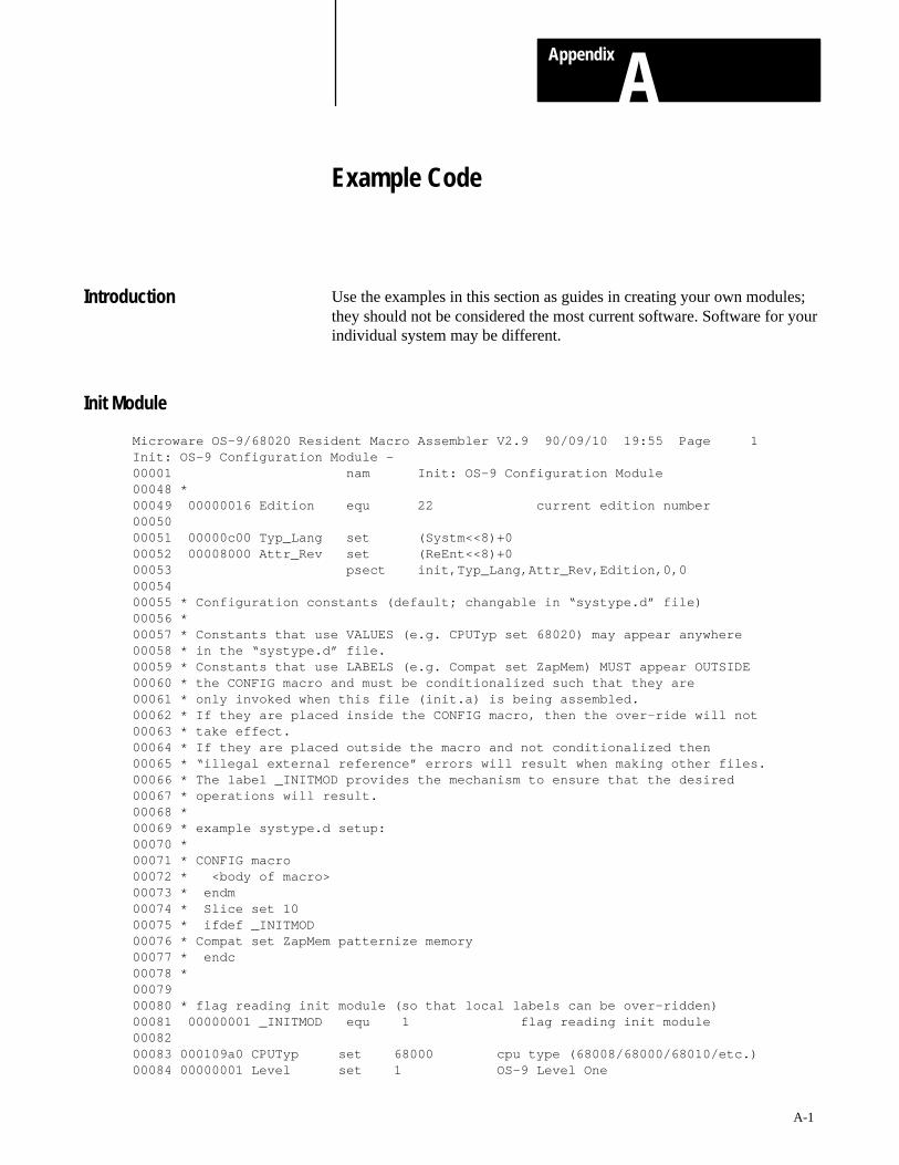
Appendix
A
A-1
Example Code
Use the examples in this section as guides in creating your own modules;they should not be considered the most current software. Software for yourindividual system may be different.
Microware OS–9/68020 Resident Macro Assembler V2.9 90/09/10 19:55 Page 1Init: OS–9 Configuration Module – 00001 nam Init: OS–9 Configuration Module 00048 *00049 00000016 Edition equ 22 current edition number00050 00051 00000c00 Typ_Lang set (Systm<<8)+0 00052 00008000 Attr_Rev set (ReEnt<<8)+0 00053 psect init,Typ_Lang,Attr_Rev,Edition,0,0 00054 00055 * Configuration constants (default; changable in “systype.d” file)00056 *00057 * Constants that use VALUES (e.g. CPUTyp set 68020) may appear anywhere00058 * in the “systype.d” file.00059 * Constants that use LABELS (e.g. Compat set ZapMem) MUST appear OUTSIDE00060 * the CONFIG macro and must be conditionalized such that they are00061 * only invoked when this file (init.a) is being assembled.00062 * If they are placed inside the CONFIG macro, then the over–ride will not00063 * take effect.00064 * If they are placed outside the macro and not conditionalized then00065 * “illegal external reference” errors will result when making other files.00066 * The label _INITMOD provides the mechanism to ensure that the desired00067 * operations will result.00068 *00069 * example systype.d setup:00070 *00071 * CONFIG macro00072 * <body of macro>00073 * endm00074 * Slice set 1000075 * ifdef _INITMOD00076 * Compat set ZapMem patternize memory00077 * endc00078 *00079 00080 * flag reading init module (so that local labels can be over–ridden)00081 00000001 _INITMOD equ 1 flag reading init module00082 00083 000109a0 CPUTyp set 68000 cpu type (68008/68000/68010/etc.)00084 00000001 Level set 1 OS–9 Level One
Introduction
Init Module
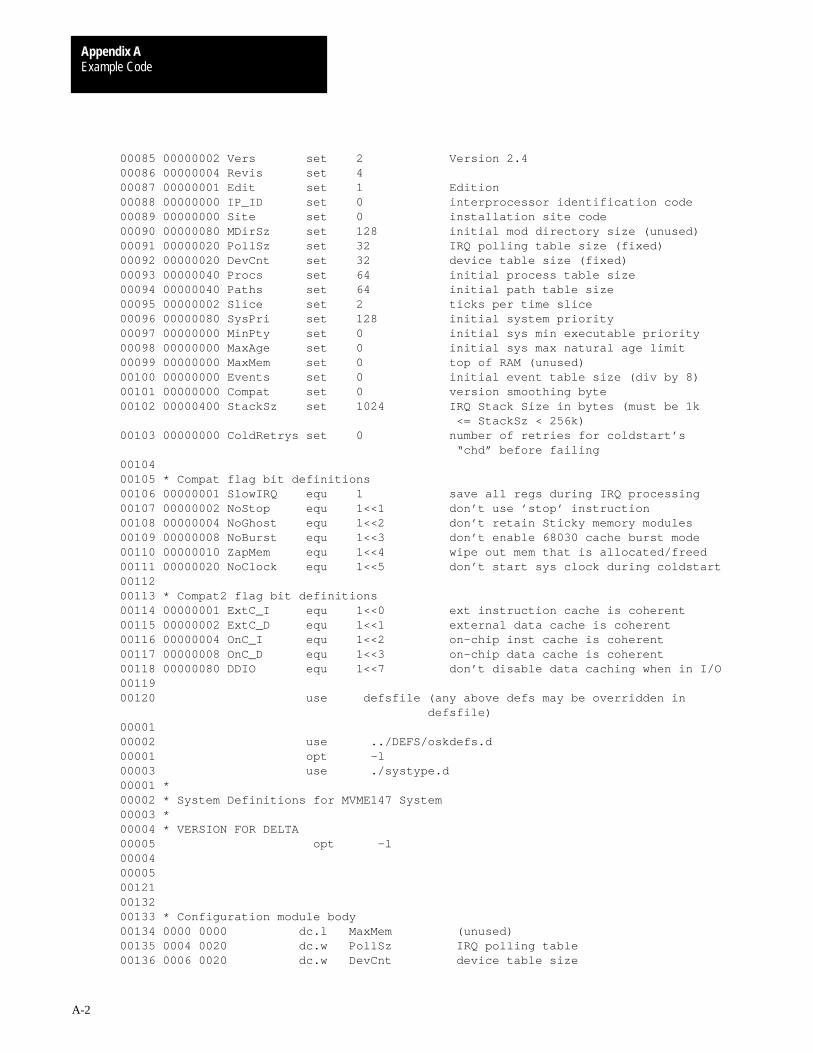
Example CodeAppendix A
A-2
00085 00000002 Vers set 2 Version 2.400086 00000004 Revis set 4 00087 00000001 Edit set 1 Edition00088 00000000 IP_ID set 0 interprocessor identification code00089 00000000 Site set 0 installation site code00090 00000080 MDirSz set 128 initial mod directory size (unused)00091 00000020 PollSz set 32 IRQ polling table size (fixed)00092 00000020 DevCnt set 32 device table size (fixed)00093 00000040 Procs set 64 initial process table size 00094 00000040 Paths set 64 initial path table size 00095 00000002 Slice set 2 ticks per time slice00096 00000080 SysPri set 128 initial system priority00097 00000000 MinPty set 0 initial sys min executable priority00098 00000000 MaxAge set 0 initial sys max natural age limit00099 00000000 MaxMem set 0 top of RAM (unused)00100 00000000 Events set 0 initial event table size (div by 8)00101 00000000 Compat set 0 version smoothing byte00102 00000400 StackSz set 1024 IRQ Stack Size in bytes (must be 1k <= StackSz < 256k)00103 00000000 ColdRetrys set 0 number of retries for coldstart’s “chd” before failing00104 00105 * Compat flag bit definitions00106 00000001 SlowIRQ equ 1 save all regs during IRQ processing00107 00000002 NoStop equ 1<<1 don’t use ’stop’ instruction00108 00000004 NoGhost equ 1<<2 don’t retain Sticky memory modules00109 00000008 NoBurst equ 1<<3 don’t enable 68030 cache burst mode00110 00000010 ZapMem equ 1<<4 wipe out mem that is allocated/freed00111 00000020 NoClock equ 1<<5 don’t start sys clock during coldstart00112 00113 * Compat2 flag bit definitions00114 00000001 ExtC_I equ 1<<0 ext instruction cache is coherent00115 00000002 ExtC_D equ 1<<1 external data cache is coherent00116 00000004 OnC_I equ 1<<2 on–chip inst cache is coherent00117 00000008 OnC_D equ 1<<3 on–chip data cache is coherent00118 00000080 DDIO equ 1<<7 don’t disable data caching when in I/O00119 00120 use defsfile (any above defs may be overridden in defsfile) 00001 00002 use ../DEFS/oskdefs.d 00001 opt –l 00003 use ./systype.d 00001 *00002 * System Definitions for MVME147 System00003 *00004 * VERSION FOR DELTA00005 opt –l 00004 00005 00121 00132 00133 * Configuration module body00134 0000 0000 dc.l MaxMem (unused)00135 0004 0020 dc.w PollSz IRQ polling table 00136 0006 0020 dc.w DevCnt device table size
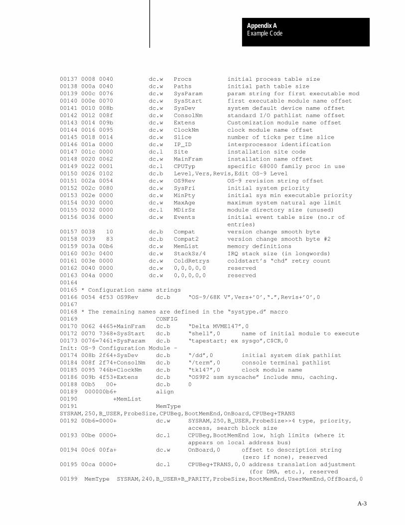
Example CodeAppendix A
A-3
00137 0008 0040 dc.w Procs initial process table size00138 000a 0040 dc.w Paths initial path table size00139 000c 0076 dc.w SysParam param string for first executable mod00140 000e 0070 dc.w SysStart first executable module name offset00141 0010 008b dc.w SysDev system default device name offset00142 0012 008f dc.w ConsolNm standard I/O pathlist name offset00143 0014 009b dc.w Extens Customization module name offset00144 0016 0095 dc.w ClockNm clock module name offset00145 0018 0014 dc.w Slice number of ticks per time slice00146 001a 0000 dc.w IP_ID interprocessor identification00147 001c 0000 dc.l Site installation site code00148 0020 0062 dc.w MainFram installation name offset00149 0022 0001 dc.l CPUTyp specific 68000 family proc in use00150 0026 0102 dc.b Level,Vers,Revis,Edit OS–9 Level00151 002a 0054 dc.w OS9Rev OS–9 revision string offset00152 002c 0080 dc.w SysPri initial system priority00153 002e 0000 dc.w MinPty initial sys min executable priority00154 0030 0000 dc.w MaxAge maximum system natural age limit00155 0032 0000 dc.l MDirSz module directory size (unused)00156 0036 0000 dc.w Events initial event table size (no.r of entries)00157 0038 10 dc.b Compat version change smooth byte00158 0039 83 dc.b Compat2 version change smooth byte #200159 003a 00b6 dc.w MemList memory definitions00160 003c 0400 dc.w StackSz/4 IRQ stack size (in longwords)00161 003e 0000 dc.w ColdRetrys coldstart’s “chd” retry count00162 0040 0000 dc.w 0,0,0,0,0 reserved00163 004a 0000 dc.w 0,0,0,0,0 reserved00164 00165 * Configuration name strings00166 0054 4f53 OS9Rev dc.b “OS–9/68K V”,Vers+’0’,“.”,Revis+’0’,0 00167 00168 * The remaining names are defined in the “systype.d” macro00169 CONFIG 00170 0062 4465+MainFram dc.b “Delta MVME147”,0 00172 0070 7368+SysStart dc.b “shell”,0 name of initial module to execute00173 0076=7461+SysParam dc.b “tapestart; ex sysgo”,C$CR,0 Init: OS–9 Configuration Module – 00174 008b 2f64+SysDev dc.b “/dd”,0 initial system disk pathlist00184 008f 2f74+ConsolNm dc.b “/term”,0 console terminal pathlist00185 0095 746b+ClockNm dc.b “tk147”,0 clock module name00186 009b 4f53+Extens dc.b “OS9P2 ssm syscache” include mmu, caching.00188 00b5 00+ dc.b 0 00189 000000b6+ align 00190 +MemList 00191 MemTypeSYSRAM,250,B_USER,ProbeSize,CPUBeg,BootMemEnd,OnBoard,CPUBeg+TRANS 00192 00b6=0000+ dc.w SYSRAM,250,B_USER,ProbeSize>>4 type, priority, access, search block size00193 00be 0000+ dc.l CPUBeg,BootMemEnd low, high limits (where it appears on local address bus)00194 00c6 00fa+ dc.w OnBoard,0 offset to description string (zero if none), reserved00195 00ca 0000+ dc.l CPUBeg+TRANS,0,0 address translation adjustment (for DMA, etc.), reserved00199 MemType SYSRAM,240,B_USER+B_PARITY,ProbeSize,BootMemEnd,UserMemEnd,OffBoard,0

Example CodeAppendix A
A-4
00200 00d6=0000+ dc.w SYSRAM,240,B_USER+B_PARITY,ProbeSize>>4 type, priority, access, search block size00201 00de 0040+ dc.l BootMemEnd,UserMemEnd low, high limits (where it appears on local address bus)00202 00e6 0107+ dc.w OffBoard,0 offset to description string (zero if none), reserved00203 00ea 0000+ dc.l 0,0,0 address translation adjustment (for DMA, etc.), reserved00207 00f6 0000+ dc.l 0 terminate list00208 00fa 6f6e+OnBoard dc.b “on–board ram”,0 00209 0107 766d+OffBoard dc.b “vme bus ram”,0 00210 00214 00218 00219 * define default caching modes (CPUTyp and system specific)00220 * NOTE: the following rules should be applied in determining00221 * the “coherency” of a cache and setting up the Compat200222 * cache function flags:00223 *00224 * – if the cache does not exits, then it is always coherent.00225 * – the on–chip cache coherency is not changable, except00226 * for the 68040. If a 68040 system is used with00227 * bus–snooping disabled, then that fact should be registered00228 * by the user defining the label NoSnoop040 in their local00229 * “systype.d” file.00230 * – the coherency of external caches is indicated by the00231 * SnoopExt definition. If the external caches are00232 * coherent or non–existant, then the label SnoopExt00233 * should be defined in “systype.d”.00234 * – the kernel will disable data caching when calling a file00235 * manager, unless the “NoDataDis” label is defined.00236 * Disabling data caching is required for systems that have00237 * drivers that use dma and don’t perform any explicit data00238 * cache flushing. If your system does NOT use dma drivers,00239 * or the drivers care for the cache, then the NoDataDis00240 * label should be defined in “systype.d”.00241 *00243 00246 * external caches are coherent or absent00247 00000003 ExtCache equ ExtC_I!ExtC_D 00252 00261 00000003 Compat2 set ExtCache 68030 on–chip caches are NOT snoopy00270 00271 * add “don’t disable data cache when in I/O” to Compat200273 00000083 Compat2 set Compat2!DDIO 00275 00277 00278 00000114 ends Errors: 00000Memory used: 45kElapsed time: 6 second(s)
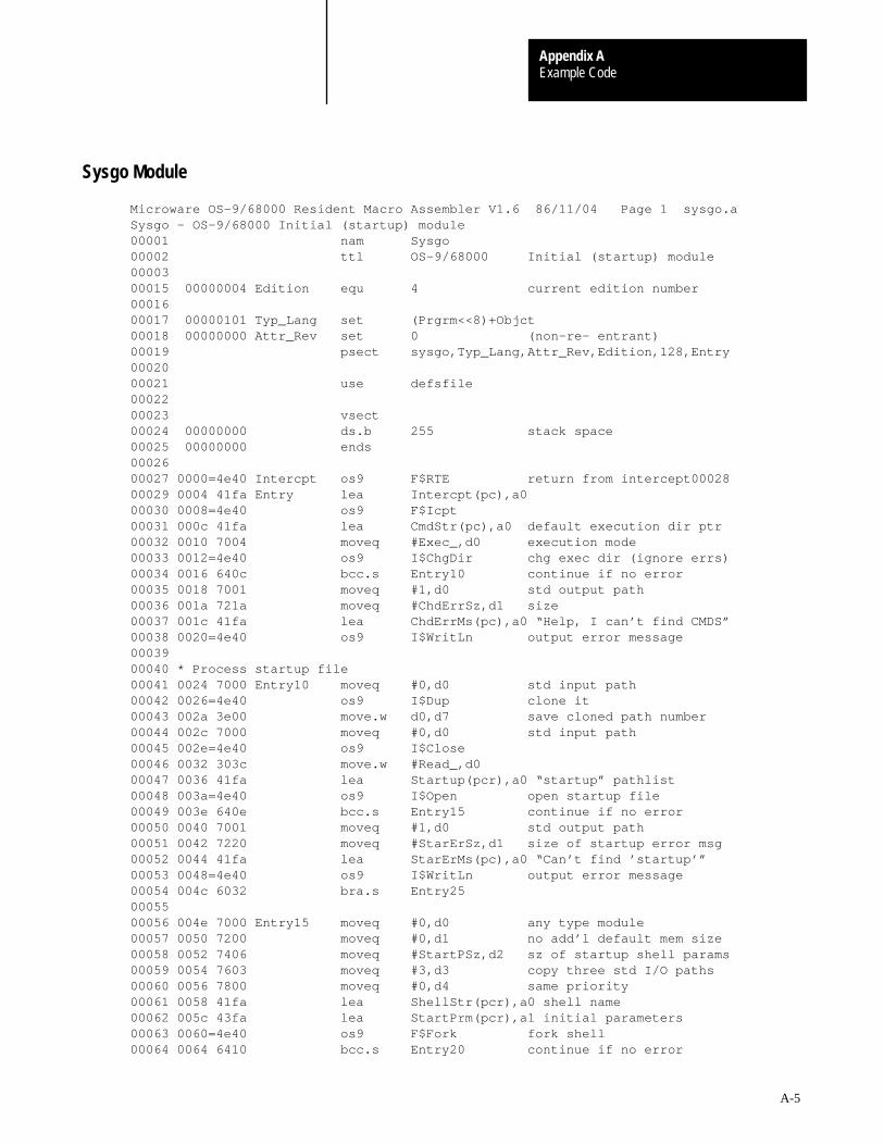
Example CodeAppendix A
A-5
Microware OS–9/68000 Resident Macro Assembler V1.6 86/11/04 Page 1 sysgo.aSysgo – OS–9/68000 Initial (startup) module00001 nam Sysgo 00002 ttl OS–9/68000 Initial (startup) module0000300015 00000004 Edition equ 4 current edition number00016 00017 00000101 Typ_Lang set (Prgrm<<8)+Objct 00018 00000000 Attr_Rev set 0 (non–re– entrant)00019 psect sysgo,Typ_Lang,Attr_Rev,Edition,128,Entry 00020 00021 use defsfile 00022 00023 vsect 00024 00000000 ds.b 255 stack space00025 00000000 ends 00026 00027 0000=4e40 Intercpt os9 F$RTE return from intercept00028 00029 0004 41fa Entry lea Intercpt(pc),a0 00030 0008=4e40 os9 F$Icpt 00031 000c 41fa lea CmdStr(pc),a0 default execution dir ptr00032 0010 7004 moveq #Exec_,d0 execution mode00033 0012=4e40 os9 I$ChgDir chg exec dir (ignore errs)00034 0016 640c bcc.s Entry10 continue if no error00035 0018 7001 moveq #1,d0 std output path00036 001a 721a moveq #ChdErrSz,d1 size00037 001c 41fa lea ChdErrMs(pc),a0 “Help, I can’t find CMDS”00038 0020=4e40 os9 I$WritLn output error message00039 00040 * Process startup file00041 0024 7000 Entry10 moveq #0,d0 std input path00042 0026=4e40 os9 I$Dup clone it00043 002a 3e00 move.w d0,d7 save cloned path number00044 002c 7000 moveq #0,d0 std input path00045 002e=4e40 os9 I$Close 00046 0032 303c move.w #Read_,d0 00047 0036 41fa lea Startup(pcr),a0 “startup” pathlist00048 003a=4e40 os9 I$Open open startup file00049 003e 640e bcc.s Entry15 continue if no error00050 0040 7001 moveq #1,d0 std output path00051 0042 7220 moveq #StarErSz,d1 size of startup error msg00052 0044 41fa lea StarErMs(pc),a0 “Can’t find ’startup’”00053 0048=4e40 os9 I$WritLn output error message00054 004c 6032 bra.s Entry25 00055 00056 004e 7000 Entry15 moveq #0,d0 any type module00057 0050 7200 moveq #0,d1 no add’l default mem size00058 0052 7406 moveq #StartPSz,d2 sz of startup shell params00059 0054 7603 moveq #3,d3 copy three std I/O paths00060 0056 7800 moveq #0,d4 same priority00061 0058 41fa lea ShellStr(pcr),a0 shell name00062 005c 43fa lea StartPrm(pcr),a1 initial parameters00063 0060=4e40 os9 F$Fork fork shell00064 0064 6410 bcc.s Entry20 continue if no error
Sysgo Module

Example CodeAppendix A
A-6
00065 0066 7001 moveq #1,d0 std output path00066 0068 7219 moveq #FrkErrSz,d1 size00067 006a 41fa lea FrkErrMs(pc),a0 “oh no, can’t fork Shell”00068 006e=4e40 os9 I$WritLn output error message00069 0072=4e40 os9 F$SysDbg crash system00070 00071 0076=4e40 Entry20 os9 F$Wait wait for death,ignore error00072 007a 7000 moveq #0,d0 std input path00073 007c=4e40 os9 I$Close close redirected “startup”00074 0080 3007 Entry25 move.w d7,d0 00075 0082=4e40 os9 I$Dup restore original std input00076 0086 3007 move.w d7,d0 00077 0088=4e40 os9 I$Close remove cloned path00078 00079 008c 7000 Loop moveq #0,d0 any type module00080 008e 7200 moveq #0,d1 default memory size00081 0090 7401 moveq #1,d2 one parameter byte (CR)00082 0092 7603 moveq #3,d3 copy std I/O paths00083 0094 7800 moveq #0,d4 same priority00084 0096 41fa lea ShellStr(pcr),a0 shell name00085 009a 43fa lea CRChar(pcr),a1 null paramter string00086 009e=4e40 os9 F$Fork fork shell00087 00a2 650a bcs.s ForkErr abort if error00088 00a4=4e40 os9 F$Wait wait for it to die00089 00a8 6504 bcs.s ForkErr 00090 00aa 4a41 tst.w d1 zero status?00091 00ac 67de beq.s Loop loop if so00092 00ae=4e40 ForkErr os9 F$PErr print error message00093 00b2 60d8 bra.s Loop 00094 00095 00b4 7368 ShellStr dc.b “shell”,0 00096 00ba=5379 FrkErrMs dc.b “Sysgo can’t fork ’shell’”,C$CR 00097 00000019 FrkErrSz equ *–FrkErrMs 00098 00099 00d3 434d CmdStr dc.b “CMDS”,0 00100 00d8=5379 ChdErrMs dc.b “Sysgo can’t chx to ’CMDS’”,C$CR 00101 0000001a ChdErrSz equ *–ChdErrMs 00102 00103 00f2 7374 Startup dc.b “startup”,0 00104 00fa=5379 StarErMs dc.b “Sysgo can’t open ’startup’ file”,C$CR 00105 00000020 StarErSz equ *–StarErMs 00106 00107 011a 2d6e StartPrm dc.b “–npxt” 00108 011f= 00 CRChar dc.b C$CR 00109 00000006 StartPSz equ *–StartPrm 00110 00000120 ends 00111 Errors: 00000Memory used: 31kElapsed time: 21 second(s)
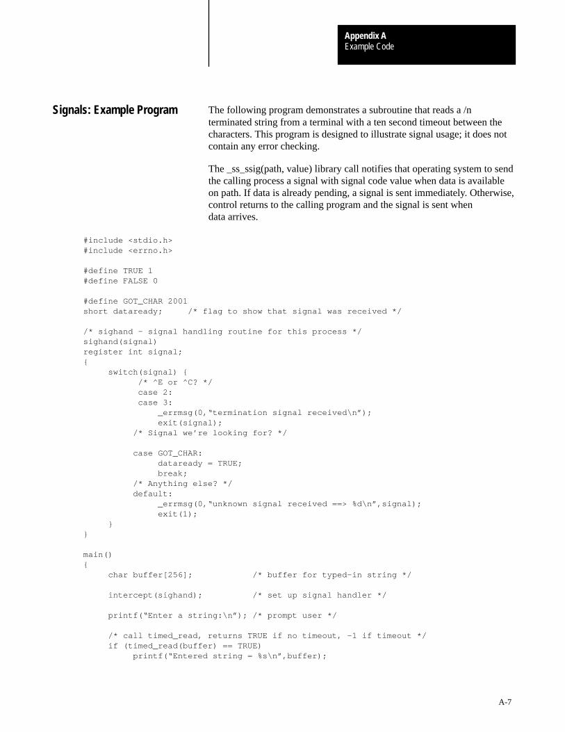
Example CodeAppendix A
A-7
The following program demonstrates a subroutine that reads a /nterminated string from a terminal with a ten second timeout between thecharacters. This program is designed to illustrate signal usage; it does notcontain any error checking.
The _ss_ssig(path, value) library call notifies that operating system to sendthe calling process a signal with signal code value when data is availableon path. If data is already pending, a signal is sent immediately. Otherwise,control returns to the calling program and the signal is sent whendata arrives.
#include <stdio.h> #include <errno.h>
#define TRUE 1 #define FALSE 0
#define GOT_CHAR 2001 short dataready; /* flag to show that signal was received */
/* sighand – signal handling routine for this process */ sighand(signal) register int signal; { switch(signal) { /* ^E or ^C? */ case 2: case 3: _errmsg(0,“termination signal received\n”); exit(signal); /* Signal we’re looking for? */
case GOT_CHAR: dataready = TRUE; break; /* Anything else? */ default: _errmsg(0,“unknown signal received ==> %d\n”,signal); exit(1); } }
main() { char buffer[256]; /* buffer for typed–in string */
intercept(sighand); /* set up signal handler */
printf(“Enter a string:\n”); /* prompt user */
/* call timed_read, returns TRUE if no timeout, –1 if timeout */ if (timed_read(buffer) == TRUE) printf(“Entered string = %s\n”,buffer);
Signals: Example Program

Example CodeAppendix A
A-8
else printf(“\nType faster next time!\n”); } int timed_read(buffer) register char *buffer; { char c = ’\0’; /* 1 character buffer for read */ short timeout = FALSE; /* flag to note timeout occurred on read */ int pos = 0; /* position holder in buffer */
/* loop until <return> entered or timeout occurs */ while ( (c != ’\n’) && (timeout == FALSE) ) { sigmask(1); /* mask signals for signal setup */ _ss_ssig(0,GOT_CHAR); /* set up to have signal sent */ sleep(10); /* sleep for 10 seconds or until signal */
/* NOTE: we had to mask signals before doing _ss_ssig() so we did not get the signal between the time we _ss_ssig()’ed and went to sleep. */
/* Now we’re awake, determine what happened */ if (!dataready) timeout = TRUE; else { read(0,&c,1); /* read the ready byte */ buffer[pos] = c; /* put it in the buffer */ pos++; /* move our position holder */ dataready = FALSE; /* mark data as read */ } }
/* loop has terminated, figure out why */ if (timeout) return –1; /* there was a timeout so return –1 */ else { buffer[pos] = ’\0’; /* null terminate the string */ return TRUE; } } #asm * C binding for sigmask(value) sigmask: move.l d1,–(sp) save d1 on the stack move.l d0,d1 get the passed parameter in the right place clr.l d0 make d0 = 0 os9 F$SigMask make the system call to mask signals bcc.s ret if no error... move.l #–1,d0 return –1 to user move.l d1,errno(a6) fill errno with error number ret move.l (sp)+,d1 restore d1 from the stack rts return to user #endasm
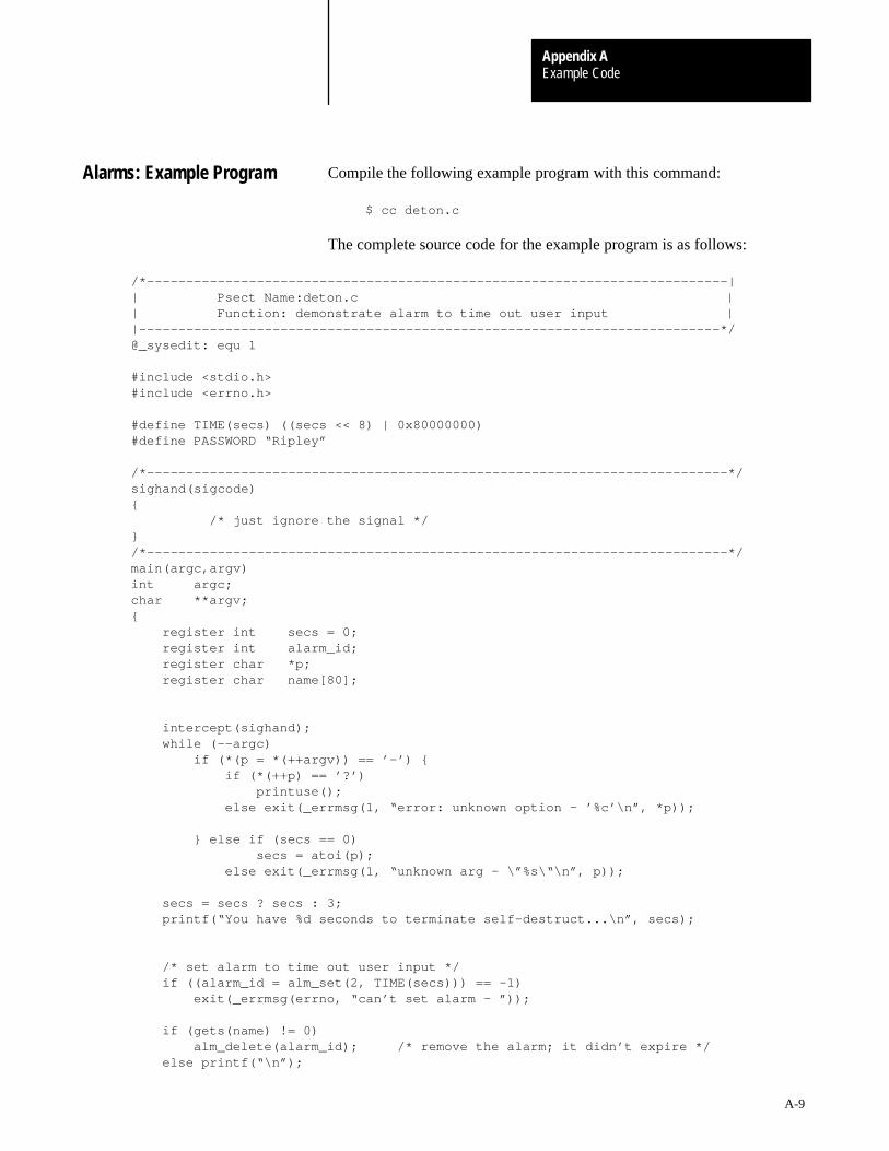
Example CodeAppendix A
A-9
Compile the following example program with this command:
$ cc deton.c
The complete source code for the example program is as follows:
/*––––––––––––––––––––––––––––––––––––––––––––––––––––––––––––––––––––––––––|| Psect Name:deton.c || Function: demonstrate alarm to time out user input ||––––––––––––––––––––––––––––––––––––––––––––––––––––––––––––––––––––––––––*/@_sysedit: equ 1
#include <stdio.h>#include <errno.h>
#define TIME(secs) ((secs << 8) | 0x80000000)#define PASSWORD “Ripley”
/*––––––––––––––––––––––––––––––––––––––––––––––––––––––––––––––––––––––––––*/sighand(sigcode){ /* just ignore the signal */}/*––––––––––––––––––––––––––––––––––––––––––––––––––––––––––––––––––––––––––*/main(argc,argv)int argc;char **argv;{ register int secs = 0; register int alarm_id; register char *p; register char name[80];
intercept(sighand); while (––argc) if (*(p = *(++argv)) == ’–’) { if (*(++p) == ’?’) printuse(); else exit(_errmsg(1, “error: unknown option – ’%c’\n”, *p));
} else if (secs == 0) secs = atoi(p); else exit(_errmsg(1, “unknown arg – \”%s\“\n”, p));
secs = secs ? secs : 3; printf(“You have %d seconds to terminate self–destruct...\n”, secs);
/* set alarm to time out user input */ if ((alarm_id = alm_set(2, TIME(secs))) == –1) exit(_errmsg(errno, “can’t set alarm – ”)); if (gets(name) != 0) alm_delete(alarm_id); /* remove the alarm; it didn’t expire */ else printf(“\n”);
Alarms: Example Program
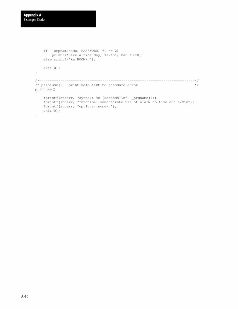
Example CodeAppendix A
A-10
if (_cmpnam(name, PASSWORD, 6) == 0) printf(“Have a nice day, %s.\n”, PASSWORD); else printf(“ka BOOM\n”);
exit(0);}
/*––––––––––––––––––––––––––––––––––––––––––––––––––––––––––––––––––––––––––*//* printuse() – print help text to standard error */printuse(){ fprintf(stderr, “syntax: %s [seconds]\n”, _prgname()); fprintf(stderr, “function: demonstrate use of alarm to time out I/O\n”); fprintf(stderr, “options: none\n”); exit(0);}
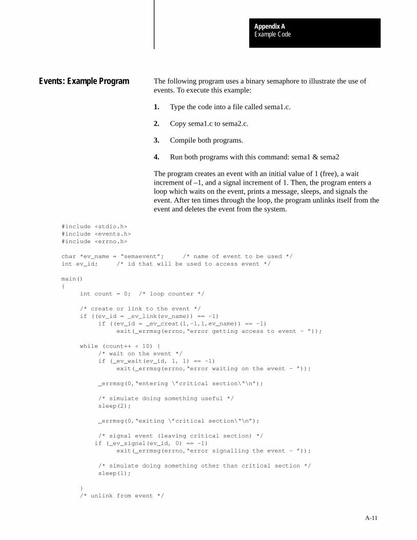
Example CodeAppendix A
A-11
The following program uses a binary semaphore to illustrate the use ofevents. To execute this example:
1. Type the code into a file called sema1.c.
2. Copy sema1.c to sema2.c.
3. Compile both programs.
4. Run both programs with this command: sema1 & sema2
The program creates an event with an initial value of 1 (free), a waitincrement of –1, and a signal increment of 1. Then, the program enters aloop which waits on the event, prints a message, sleeps, and signals theevent. After ten times through the loop, the program unlinks itself from theevent and deletes the event from the system.
#include <stdio.h> #include <events.h> #include <errno.h>
char *ev_name = “semaevent”; /* name of event to be used */ int ev_id; /* id that will be used to access event */
main() { int count = 0; /* loop counter */
/* create or link to the event */ if ((ev_id = _ev_link(ev_name)) == –1) if ((ev_id = _ev_creat(1,–1,1,ev_name)) == –1) exit(_errmsg(errno,“error getting access to event – ”));
while (count++ < 10) { /* wait on the event */ if (_ev_wait(ev_id, 1, 1) == –1) exit(_errmsg(errno,“error waiting on the event – ”));
_errmsg(0,“entering \”critical section\“\n”);
/* simulate doing something useful */ sleep(2);
_errmsg(0,“exiting \”critical section\“\n”);
/* signal event (leaving critical section) */ if (_ev_signal(ev_id, 0) == –1) exit(_errmsg(errno,“error signalling the event – ”));
/* simulate doing something other than critical section */ sleep(1);
} /* unlink from event */
Events: Example Program
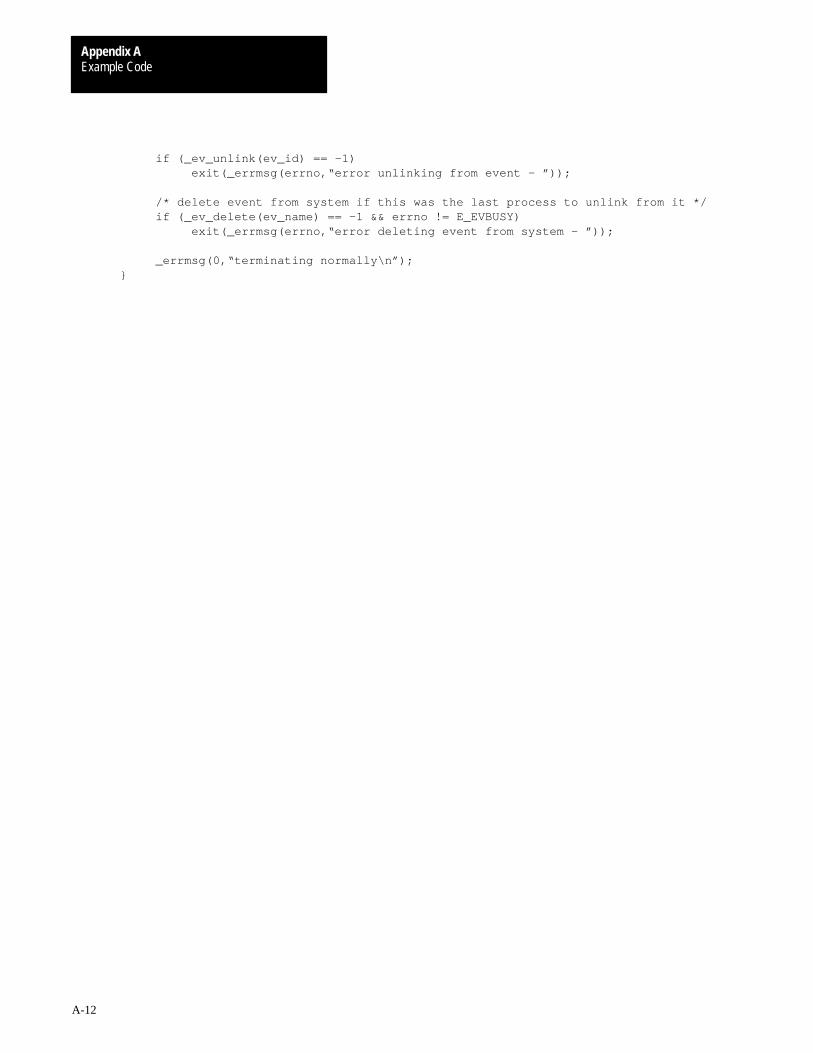
Example CodeAppendix A
A-12
if (_ev_unlink(ev_id) == –1) exit(_errmsg(errno,“error unlinking from event – ”));
/* delete event from system if this was the last process to unlink from it */ if (_ev_delete(ev_name) == –1 && errno != E_EVBUSY) exit(_errmsg(errno,“error deleting event from system – ”));
_errmsg(0,“terminating normally\n”); }
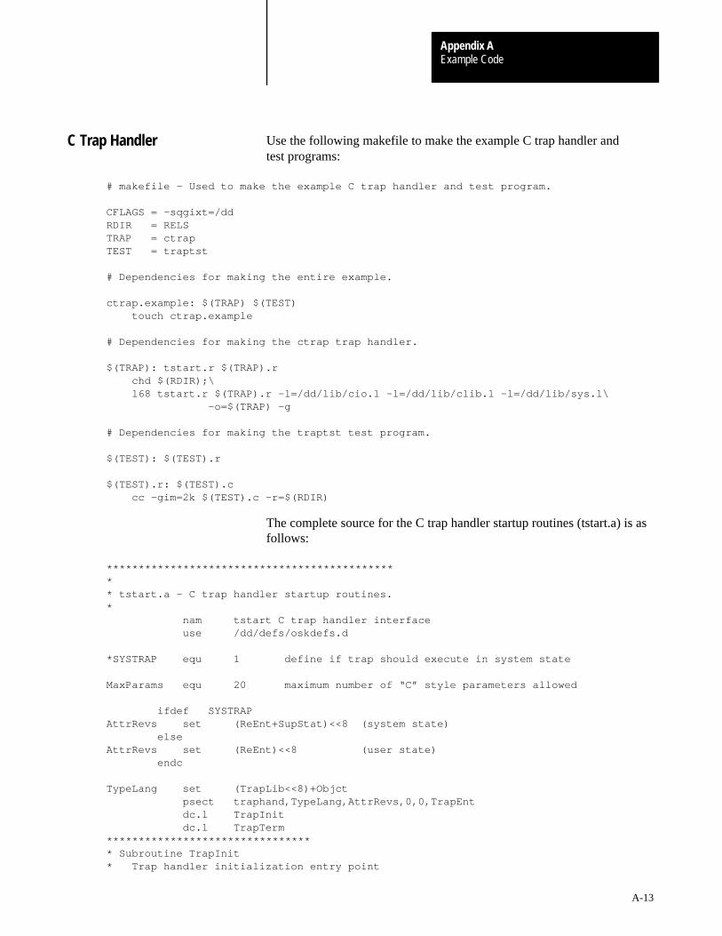
Example CodeAppendix A
A-13
Use the following makefile to make the example C trap handler andtest programs:
# makefile – Used to make the example C trap handler and test program.
CFLAGS = –sqgixt=/ddRDIR = RELSTRAP = ctrapTEST = traptst
# Dependencies for making the entire example.
ctrap.example: $(TRAP) $(TEST) touch ctrap.example
# Dependencies for making the ctrap trap handler.
$(TRAP): tstart.r $(TRAP).r chd $(RDIR);\ l68 tstart.r $(TRAP).r –l=/dd/lib/cio.l –l=/dd/lib/clib.l –l=/dd/lib/sys.l\ –o=$(TRAP) –g
# Dependencies for making the traptst test program.
$(TEST): $(TEST).r
$(TEST).r: $(TEST).c cc –gim=2k $(TEST).c –r=$(RDIR)
The complete source for the C trap handler startup routines (tstart.a) is asfollows:
********************************************** * tstart.a – C trap handler startup routines.* nam tstart C trap handler interface use /dd/defs/oskdefs.d
*SYSTRAP equ 1 define if trap should execute in system state
MaxParams equ 20 maximum number of “C” style parameters allowed
ifdef SYSTRAPAttrRevs set (ReEnt+SupStat)<<8 (system state) elseAttrRevs set (ReEnt)<<8 (user state) endc
TypeLang set (TrapLib<<8)+Objct psect traphand,TypeLang,AttrRevs,0,0,TrapEnt dc.l TrapInit dc.l TrapTerm********************************* Subroutine TrapInit* Trap handler initialization entry point
C Trap Handler
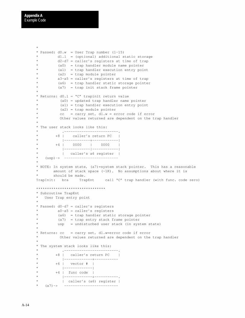
Example CodeAppendix A
A-14
** Passed: d0.w = User Trap number (1–15)* d1.l = (optional) additional static storage* d2–d7 = caller’s registers at time of trap* (a0) = trap handler module name pointer* (a1) = trap handler execution entry point* (a2) = trap module pointer* a3–a5 = caller’s registers at time of trap* (a6) = trap handler static storage pointer* (a7) = trap init stack frame pointer** Returns: d0.l = “C” trapinit return value* (a0) = updated trap handler name pointer* (a1) = trap handler execution entry point* (a2) = trap module pointer* cc = carry set, d1.w = error code if error* Other values returned are dependent on the trap handler** The user stack looks like this:* .–––––––––––––––––––––––––.* +8 | caller’s return PC |* |––––––––––––+––––––––––––|* +4 | 0000 | 0000 |* |––––––––––––|––––––––––––|* | caller’s a6 register |* (usp)–> –––––––––––––––––––––––––** NOTE: In system state, (a7)=system stack pointer. This has a reasonable* amount of stack space (~1K). No assumptions about where it is * should be made.TrapInit: bra TrapEnt call “C” trap handler (with func. code zero)
********************************* Subroutine TrapEnt* User Trap entry point** Passed: d0–d7 = caller’s registers* a0–a5 = caller’s registers* (a6) = trap handler static storage pointer* (a7) = trap entry stack frame pointer* usp = undisturbed user stack (in system state)** Returns: cc = carry set, d1.w=error code if error* Other values returned are dependent on the trap handler** The system stack looks like this:* .–––––––––––––––––––––––––.* +8 | caller’s return PC |* |–––––––––––––+–––––––––––* +6 | vector # |* |–––––––––––––|* +4 | func code |* |–––––––––––––+–––––––––––.* | caller’s (a6) register |* (a7)–> –––––––––––––––––––––––––

Example CodeAppendix A
A-15
org 0 stack offset definitionsS_CParams do.l MaxParamsS_a0 do.l 1 caller’s a0 regS_a1 do.l 1caller’s a1 regS_a6 do.l 1 caller’s a6 regS_func do.w 1 trap function codeS_vect do.w 1 user trap exception offsetS_cleanup equ .S_pc do.l 1 return pc
TrapEnt: movem.l a0–a1,–(a7) save regs lea –MaxParams*4(a7),a7 allocate parameter space lea S_CParams(a7),a1 ptr to C parameter area ifdef SYSTRAP move usp,a0 caller’s parameters are on user stack ptr adda.l #12,a0 above two rts pc’s else lea S_pc+16(a7),a0 caller’s remaining C parameters ptr endc
moveq #MaxParams–1,d1 number of (potential) parametersTrap10 move.l (a0)+,(a1)+ copy caller’s params from user stack dbra d1,Trap10 moveq #0,d0 sweep reg move.w S_func(a7),d0 1st param = func move.l S_a6(a7),d1 2nd param = caller’s (a6) bsr ctrap execute C traphandler Trap90 movea.l S_a6(a7),a6 restore caller’s a6 lea S_cleanup(a7),a7 discard scratch rts return to user program
********************************* Subroutine TrapTerm* Terminate trap handler servicing.** As of this release (OS–9 V2.3) the trap termination entry point* is never called by the OS–9 kernel. Documentation details will* be available when a working implementation exists.
TrapTerm: move.w #1<<8+199,d1 never called; so if it gets here... OS9 F$Exit crash program (Error 001:199)
ends
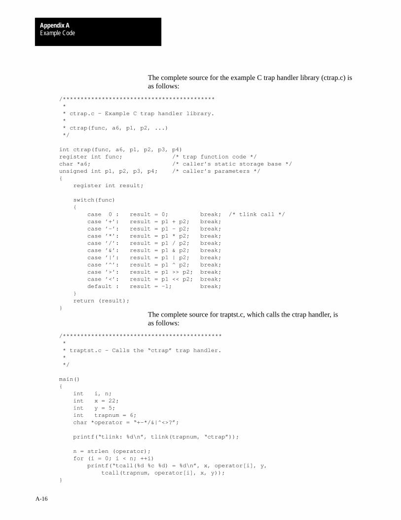
Example CodeAppendix A
A-16
The complete source for the example C trap handler library (ctrap.c) isas follows:
/******************************************* * * ctrap.c – Example C trap handler library. * * ctrap(func, a6, p1, p2, ...) */ int ctrap(func, a6, p1, p2, p3, p4)register int func; /* trap function code */char *a6; /* caller’s static storage base */unsigned int p1, p2, p3, p4; /* caller’s parameters */{ register int result;
switch(func) { case 0 : result = 0; break; /* tlink call */ case ’+’: result = p1 + p2; break; case ’–’: result = p1 – p2; break; case ’*’: result = p1 * p2; break; case ’/’: result = p1 / p2; break; case ’&’: result = p1 & p2; break; case ’|’: result = p1 | p2; break; case ’^’: result = p1 ^ p2; break; case ’>’: result = p1 >> p2; break; case ’<’: result = p1 << p2; break; default : result = –1; break; } return (result);}
The complete source for traptst.c, which calls the ctrap handler, isas follows:
/********************************************* * * traptst.c – Calls the “ctrap” trap handler. * */
main(){ int i, n; int x = 22; int y = 5; int trapnum = 6; char *operator = “+–*/&|^<>?”;
printf(“tlink: %d\n”, tlink(trapnum, “ctrap”));
n = strlen (operator); for (i = 0; i < n; ++i) printf(“tcall(%d %c %d) = %d\n”, x, operator[i], y, tcall(trapnum, operator[i], x, y));}
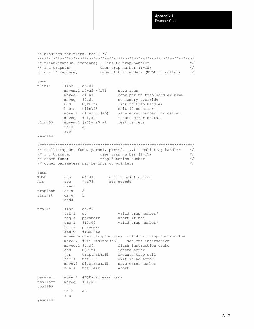
Example CodeAppendix A
A-17
/* bindings for tlink, tcall *//********************************************************************//* tlink(trapnum, trapname) – link to trap handler *//* int trapnum; user trap number (1–15) *//* char *trapname; name of trap module (NULL to unlink) */
#asmtlink: link a5,#0 movem.l a0–a2,–(a7) save regs movea.l d1,a0 copy ptr to trap handler name moveq #0,d1 no memory override OS9 F$TLink link to trap handler bcc.s tlink99 exit if no error move.l d1,errno(a6) save error number for caller moveq #–1,d0 return error statustlink99 movem.l (a7)+,a0–a2 restore regs unlk a5 rts#endasm
/********************************************************************//* tcall(trapnum, func, param1, param2, ...) – call trap handler *//* int trapnum; user trap number (1–15) *//* short func; trap function number *//* other parameters may be ints or pointers */
#asmTRAP equ $4e40 user trap(0) opcodeRTS equ $4e75 rts opcode vsecttrapinst ds.w 2rtsinst ds.w 1 ends
tcall: link a5,#0 tst.l d0 valid trap number? beq.s paramerr abort if not cmp.l #15,d0 valid trap number? bhi.s paramerr add.w #TRAP,d0 movem.w d0–d1,trapinst(a6) build usr trap instruction move.w #RTS,rtsinst(a6) set rts instruction moveq.l #0,d0 flush instruction cache os9 F$CCtl ignore error jsr trapinst(a6) execute trap call bcc.s tcall99 exit if no error move.l d1,errno(a6) save error number bra.s tcallerr abort
paramerr move.l #E$Param,errno(a6)tcallerr moveq #–1,d0tcall99 unlk a5 rts#endasm

Example CodeAppendix A
A-18
Microware OS–9/68020 Resident Macro Assembler V2.9 90/12/07 15:29 Page 1 ../io/d0.aD0 Device Descriptor – Device Descriptor for Floppy disk controller00001 nam D0 Device Descriptor 00002 use defsfile 00001 00002 use ../DEFS/oskdefs.d 00001 opt –l 00003 use ./systype.d 00001 * System Definitions for MVME147 System00002 *00003 opt –l 00004 00005 00003 use ../io/rbfdesc.a 00001 00002 ttl Device Descriptor for Floppy disk controller 00003 00045 0000000e Edition equ 14 current edition number00046 00047 * PD_DNS values00048 00000000 Single equ 0 FM encoded media00049 00000001 Double equ 1 MFM encoded media/double–track density00050 00000002 Quad equ 1<<1 Quad track density00051 00000004 Octal equ 1<<2 Octal track density00052 00053 * PD_TYP values00054 * Note: For pre–V2.4 Five/Eight defines the disk size, rotational00055 * speed and data transfer rate. From V2.4 the physical size00056 * is defined in bits 4 – 1, and PD_Rate defines the rotational00057 * speed and data transfer rate.00058 00059 * floppy disk definitions00060 00000000 Five equ 0<<0 drive is 5 1/4”00061 00000001 Eight equ 1<<0 drive is 8”00062 00000000 SizeOld equ 0<<1 size/speed defined by bit 0 value (pre–V2.4)00063 00000002 Size8 equ 1<<1 physical size is 8”00064 00000004 Size5 equ 2<<1 physical size is 5 1/4”00065 00000006 Size3 equ 3<<1 physical size is 3 1/2”00066 00067 * hard disk definitions00068 00000040 HRemov equ 1<<6 hard disk is removable00069 00000080 Hard equ 1<<7 hard disk media00070 00071 * PD_Rate values00072 * Note: V2.4 drivers should derive the disk data transfer rate and00073 * rotational speed from this field if PD_TYP, bits 4 – 1 are00074 * non–zero. If not, then PD_TYP, bit 0 infers these.00075 00000000 rpm300 equ 0 rotational speed is 300 rpm00076 00000001 rpm360 equ 1 rotational speed is 360 rpm00077 00000002 rpm600 equ 2 rotational speed is 600 rpm00078 00000000 xfr125K equ 0<<4 transfer rate is 125K bits/sec
RBF Device Descriptor

Example CodeAppendix A
A-19
00079 00000010 xfr250K equ 1<<4 transfer rate is 250K bits/sec
00080 00000020 xrf300K equ 2<<4 transfer rate is 300K bits/sec00081 00000030 xfr500K equ 3<<4 transfer rate is 500K bits/sec00082 00000040 xfr1M equ 4<<4 transfer rate is 1M bits/sec00083 00000050 xfr2M equ 5<<4 transfer rate is 2M bits/sec00084 00000060 xfr5M equ 6<<4 transfer rate is 5M bits/sec00085 00086 * PD_VFY values00087 00000001 ON equ 1 “no–verify” ON00088 00000000 OFF equ 0 “no–verify” OFF (i.e. verify is ON!)00089 00090 * macro parameter #6 definitions (drive type)00091 00092 00000001 d877 equ 1 single density 8”00093 00000004 dd877 equ 4 double density 8”00094 00000002 d540 equ 2 single density 5 1/4” 40 trk00095 00000005 dd540 equ 5 double density 5 1/4” 40 trk00096 00000003 d580 equ 3 single density 5 1/4” 80 trk00097 00000006 dd580 equ 6 double density 5 1/4” 80 trk00098 00000007 ramdisk equ 7 volatile ram disk00099 00000008 nvramdisk equ 8 non–volatile ram disk00100 00000009 uv580 equ 9 universal 5 1/4” 80 track00101 0000000a autosize equ 10 autosize device (SS_DSize tellsmedia size)00102 0000000b dd380 equ 11 double density 3 1/2”, 80 trk00103 0000000c uv380 equ 12 universal 3 1/2” 80 track00104 0000000d hd580 equ 13 double density 5 1/4” 80 track ’8” image’00105 0000000e ed380 equ 14 double density 3 1/2” 80 track, 4M byte unformatted00106 0000000f hd577 equ 15 double density 5 1/4” 77 track ’8” image’00107 00000010 uv577 equ 16 universal 5 1/4” ’8” image’00108 00000011 uv877 equ 17 universal 8”00109 00110 00000003 Density set BitDns+(TrkDns<<1) 00111 00000024 DiskType set DiskKind+(DnsTrk0<<5) 00112 00113 00000f00 TypeLang set (Devic<<8)+0 00114 00008000 Attr_Rev set (ReEnt<<8)+0 00115 00116 psect RBFDesc,TypeLang,Attr_Rev,Edition,0,0 00117 00118 0000 fffe dc.l Port port address00119 0004 45 dc.b Vector auto–vector trap assignment00120 0005 04 dc.b IRQLevel IRQ hardware interrupt level00121 0006 05 dc.b Priority irq polling priority00122 0007 a7 dc.b Mode device mode capabilities00123 0008 0048 dc.w FileMgr file manager name offset00124 000a 004c dc.w DevDrv device driver name offset00125 000c 0053 dc.w DevCon (reserved)00126 000e 0000 dc.w 0,0,0,0 reserved00127 0016 0030 dc.w OptLen 00128
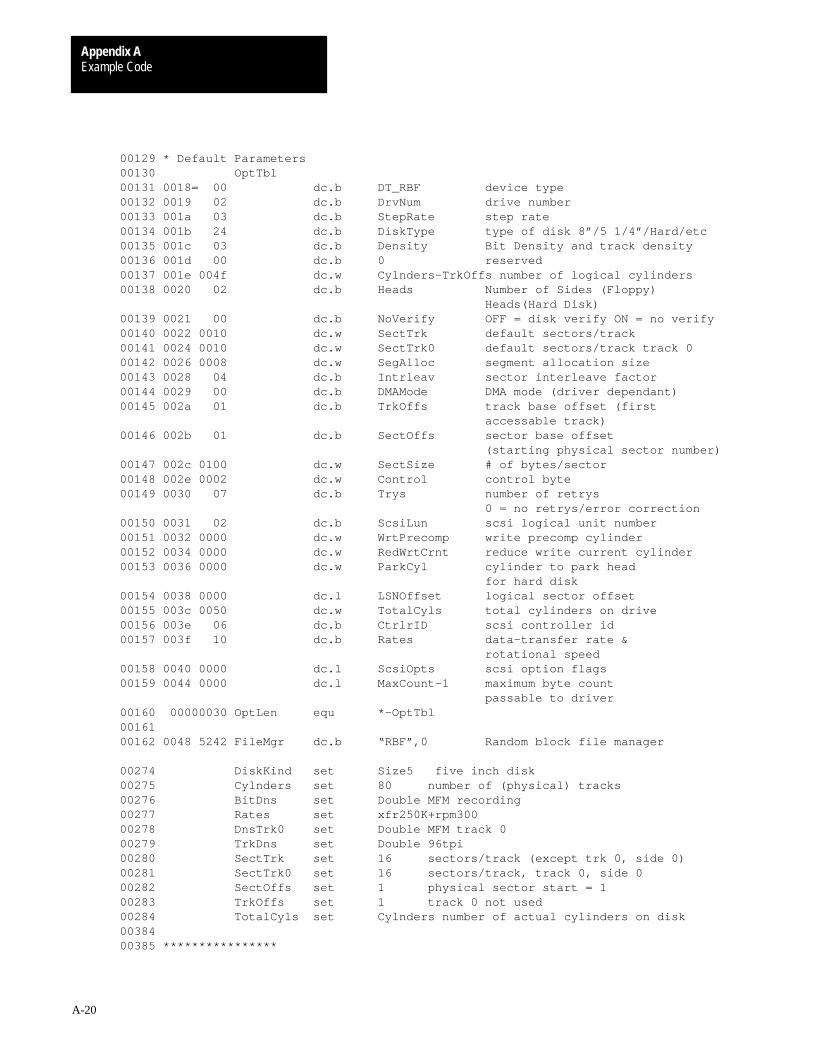
Example CodeAppendix A
A-20
00129 * Default Parameters00130 OptTbl 00131 0018= 00 dc.b DT_RBF device type00132 0019 02 dc.b DrvNum drive number00133 001a 03 dc.b StepRate step rate00134 001b 24 dc.b DiskType type of disk 8”/5 1/4”/Hard/etc00135 001c 03 dc.b Density Bit Density and track density00136 001d 00 dc.b 0 reserved00137 001e 004f dc.w Cylnders–TrkOffs number of logical cylinders00138 0020 02 dc.b Heads Number of Sides (Floppy) Heads(Hard Disk)00139 0021 00 dc.b NoVerify OFF = disk verify ON = no verify00140 0022 0010 dc.w SectTrk default sectors/track00141 0024 0010 dc.w SectTrk0 default sectors/track track 000142 0026 0008 dc.w SegAlloc segment allocation size00143 0028 04 dc.b Intrleav sector interleave factor00144 0029 00 dc.b DMAMode DMA mode (driver dependant)00145 002a 01 dc.b TrkOffs track base offset (first accessable track)00146 002b 01 dc.b SectOffs sector base offset (starting physical sector number)00147 002c 0100 dc.w SectSize # of bytes/sector00148 002e 0002 dc.w Control control byte00149 0030 07 dc.b Trys number of retrys 0 = no retrys/error correction00150 0031 02 dc.b ScsiLun scsi logical unit number00151 0032 0000 dc.w WrtPrecomp write precomp cylinder00152 0034 0000 dc.w RedWrtCrnt reduce write current cylinder00153 0036 0000 dc.w ParkCyl cylinder to park head for hard disk00154 0038 0000 dc.l LSNOffset logical sector offset00155 003c 0050 dc.w TotalCyls total cylinders on drive00156 003e 06 dc.b CtrlrID scsi controller id00157 003f 10 dc.b Rates data–transfer rate & rotational speed00158 0040 0000 dc.l ScsiOpts scsi option flags00159 0044 0000 dc.l MaxCount–1 maximum byte count passable to driver00160 00000030 OptLen equ *–OptTbl 00161 00162 0048 5242 FileMgr dc.b “RBF”,0 Random block file manager
00274 DiskKind set Size5 five inch disk 00275 Cylnders set 80 number of (physical) tracks 00276 BitDns set Double MFM recording 00277 Rates set xfr250K+rpm300 00278 DnsTrk0 set Double MFM track 0 00279 TrkDns set Double 96tpi 00280 SectTrk set 16 sectors/track (except trk 0, side 0) 00281 SectTrk0 set 16 sectors/track, track 0, side 0 00282 SectOffs set 1 physical sector start = 1 00283 TrkOffs set 1 track 0 not used 00284 TotalCyls set Cylnders number of actual cylinders on disk 00384 00385 ****************
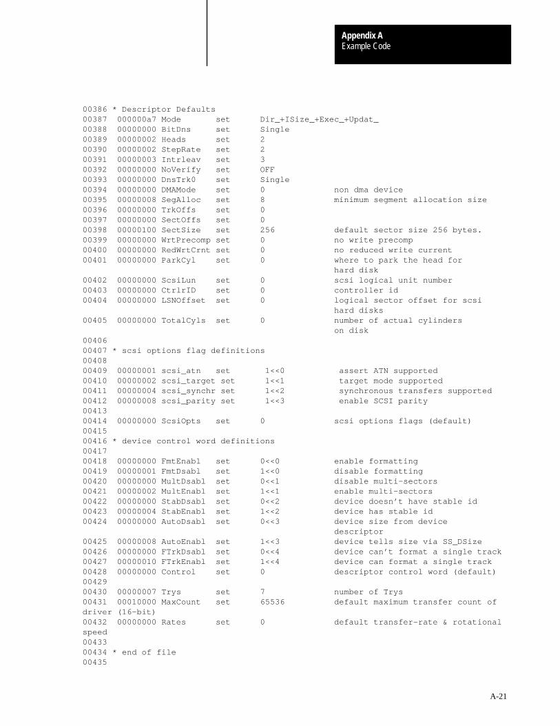
Example CodeAppendix A
A-21
00386 * Descriptor Defaults00387 000000a7 Mode set Dir_+ISize_+Exec_+Updat_ 00388 00000000 BitDns set Single 00389 00000002 Heads set 2 00390 00000002 StepRate set 2 00391 00000003 Intrleav set 3 00392 00000000 NoVerify set OFF 00393 00000000 DnsTrk0 set Single 00394 00000000 DMAMode set 0 non dma device00395 00000008 SegAlloc set 8 minimum segment allocation size00396 00000000 TrkOffs set 0 00397 00000000 SectOffs set 0 00398 00000100 SectSize set 256 default sector size 256 bytes.00399 00000000 WrtPrecomp set 0 no write precomp00400 00000000 RedWrtCrnt set 0 no reduced write current00401 00000000 ParkCyl set 0 where to park the head for hard disk00402 00000000 ScsiLun set 0 scsi logical unit number00403 00000000 CtrlrID set 0 controller id00404 00000000 LSNOffset set 0 logical sector offset for scsi hard disks00405 00000000 TotalCyls set 0 number of actual cylinders on disk00406 00407 * scsi options flag definitions00408 00409 00000001 scsi_atn set 1<<0 assert ATN supported00410 00000002 scsi_target set 1<<1 target mode supported00411 00000004 scsi_synchr set 1<<2 synchronous transfers supported00412 00000008 scsi_parity set 1<<3 enable SCSI parity00413 00414 00000000 ScsiOpts set 0 scsi options flags (default)00415 00416 * device control word definitions00417 00418 00000000 FmtEnabl set 0<<0 enable formatting00419 00000001 FmtDsabl set 1<<0 disable formatting00420 00000000 MultDsabl set 0<<1 disable multi–sectors00421 00000002 MultEnabl set 1<<1 enable multi–sectors00422 00000000 StabDsabl set 0<<2 device doesn’t have stable id00423 00000004 StabEnabl set 1<<2 device has stable id00424 00000000 AutoDsabl set 0<<3 device size from device descriptor00425 00000008 AutoEnabl set 1<<3 device tells size via SS_DSize00426 00000000 FTrkDsabl set 0<<4 device can’t format a single track00427 00000010 FTrkEnabl set 1<<4 device can format a single track00428 00000000 Control set 0 descriptor control word (default)00429 00430 00000007 Trys set 7 number of Trys00431 00010000 MaxCount set 65536 default maximum transfer count ofdriver (16–bit)00432 00000000 Rates set 0 default transfer–rate & rotationalspeed00433 00434 * end of file00435
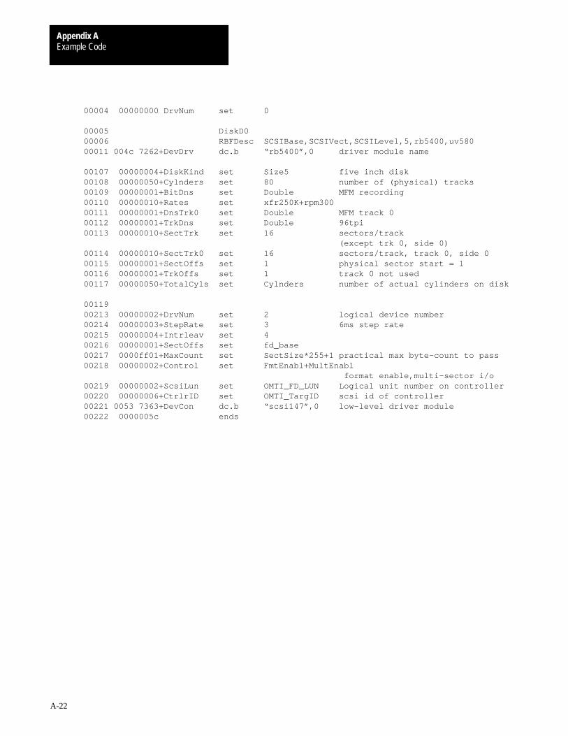
Example CodeAppendix A
A-22
00004 00000000 DrvNum set 0
00005 DiskD0 00006 RBFDesc SCSIBase,SCSIVect,SCSILevel,5,rb5400,uv580 00011 004c 7262+DevDrv dc.b “rb5400”,0 driver module name
00107 00000004+DiskKind set Size5 five inch disk00108 00000050+Cylnders set 80 number of (physical) tracks00109 00000001+BitDns set Double MFM recording00110 00000010+Rates set xfr250K+rpm300 00111 00000001+DnsTrk0 set Double MFM track 000112 00000001+TrkDns set Double 96tpi00113 00000010+SectTrk set 16 sectors/track (except trk 0, side 0)00114 00000010+SectTrk0 set 16 sectors/track, track 0, side 000115 00000001+SectOffs set 1 physical sector start = 100116 00000001+TrkOffs set 1 track 0 not used00117 00000050+TotalCyls set Cylnders number of actual cylinders on disk
00119 00213 00000002+DrvNum set 2 logical device number00214 00000003+StepRate set 3 6ms step rate00215 00000004+Intrleav set 4 00216 00000001+SectOffs set fd_base 00217 0000ff01+MaxCount set SectSize*255+1 practical max byte–count to pass00218 00000002+Control set FmtEnabl+MultEnabl format enable,multi–sector i/o00219 00000002+ScsiLun set OMTI_FD_LUN Logical unit number on controller00220 00000006+CtrlrID set OMTI_TargID scsi id of controller00221 0053 7363+DevCon dc.b “scsi147”,0 low–level driver module00222 0000005c ends
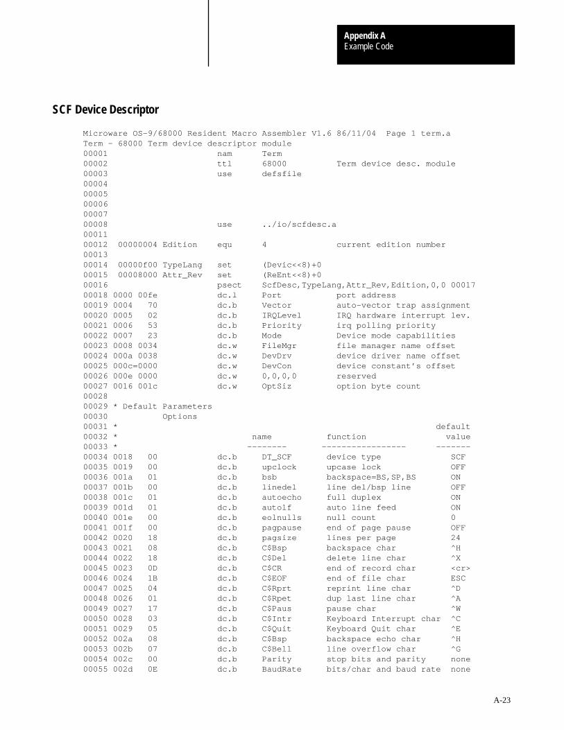
Example CodeAppendix A
A-23
Microware OS–9/68000 Resident Macro Assembler V1.6 86/11/04 Page 1 term.aTerm – 68000 Term device descriptor module00001 nam Term 00002 ttl 68000 Term device desc. module00003 use defsfile 00004 000050000600007 00008 use ../io/scfdesc.a 00011 00012 00000004 Edition equ 4 current edition number00013 00014 00000f00 TypeLang set (Devic<<8)+0 00015 00008000 Attr_Rev set (ReEnt<<8)+0 00016 psect ScfDesc,TypeLang,Attr_Rev,Edition,0,0 00017 00018 0000 00fe dc.l Port port address00019 0004 70 dc.b Vector auto–vector trap assignment00020 0005 02 dc.b IRQLevel IRQ hardware interrupt lev.00021 0006 53 dc.b Priority irq polling priority00022 0007 23 dc.b Mode Device mode capabilities00023 0008 0034 dc.w FileMgr file manager name offset00024 000a 0038 dc.w DevDrv device driver name offset00025 000c=0000 dc.w DevCon device constant’s offset00026 000e 0000 dc.w 0,0,0,0 reserved00027 0016 001c dc.w OptSiz option byte count00028 00029 * Default Parameters00030 Options 00031 * default00032 * name function value00033 * –––––––– ––––––––––––––––– –––––––00034 0018 00 dc.b DT_SCF device type SCF00035 0019 00 dc.b upclock upcase lock OFF00036 001a 01 dc.b bsb backspace=BS,SP,BS ON00037 001b 00 dc.b linedel line del/bsp line OFF00038 001c 01 dc.b autoecho full duplex ON00039 001d 01 dc.b autolf auto line feed ON00040 001e 00 dc.b eolnulls null count 000041 001f 00 dc.b pagpause end of page pause OFF00042 0020 18 dc.b pagsize lines per page 2400043 0021 08 dc.b C$Bsp backspace char ^H00044 0022 18 dc.b C$Del delete line char ^X00045 0023 0D dc.b C$CR end of record char <cr>00046 0024 1B dc.b C$EOF end of file char ESC00047 0025 04 dc.b C$Rprt reprint line char ^D00048 0026 01 dc.b C$Rpet dup last line char ^A00049 0027 17 dc.b C$Paus pause char ^W00050 0028 03 dc.b C$Intr Keyboard Interrupt char ^C00051 0029 05 dc.b C$Quit Keyboard Quit char ^E00052 002a 08 dc.b C$Bsp backspace echo char ^H00053 002b 07 dc.b C$Bell line overflow char ^G00054 002c 00 dc.b Parity stop bits and parity none00055 002d 0E dc.b BaudRate bits/char and baud rate none
SCF Device Descriptor
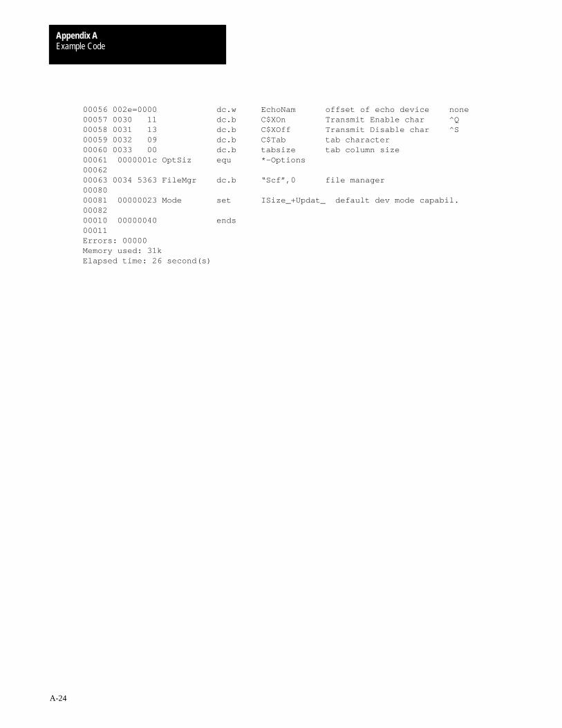
Example CodeAppendix A
A-24
00056 002e=0000 dc.w EchoNam offset of echo device none00057 0030 11 dc.b C$XOn Transmit Enable char ^Q00058 0031 13 dc.b C$XOff Transmit Disable char ^S00059 0032 09 dc.b C$Tab tab character00060 0033 00 dc.b tabsize tab column size 00061 0000001c OptSiz equ *–Options 00062 00063 0034 5363 FileMgr dc.b “Scf”,0 file manager00080 00081 00000023 Mode set ISize_+Updat_ default dev mode capabil.00082 00010 00000040 ends 00011 Errors: 00000Memory used: 31kElapsed time: 26 second(s)
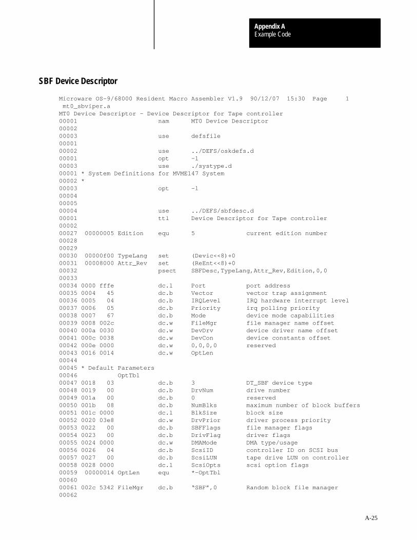
Example CodeAppendix A
A-25
Microware OS–9/68000 Resident Macro Assembler V1.9 90/12/07 15:30 Page 1 mt0_sbviper.aMT0 Device Descriptor – Device Descriptor for Tape controller00001 nam MT0 Device Descriptor 00002 00003 use defsfile 00001 00002 use ../DEFS/oskdefs.d 00001 opt –l 00003 use ./systype.d 00001 * System Definitions for MVME147 System00002 *00003 opt –l 00004 00005 00004 use ../DEFS/sbfdesc.d 00001 ttl Device Descriptor for Tape controller 00002 00027 00000005 Edition equ 5 current edition number00028 00029 00030 00000f00 TypeLang set (Devic<<8)+0 00031 00008000 Attr_Rev set (ReEnt<<8)+0 00032 psect SBFDesc,TypeLang,Attr_Rev,Edition,0,0 00033 00034 0000 fffe dc.l Port port address00035 0004 45 dc.b Vector vector trap assignment00036 0005 04 dc.b IRQLevel IRQ hardware interrupt level00037 0006 05 dc.b Priority irq polling priority00038 0007 67 dc.b Mode device mode capabilities00039 0008 002c dc.w FileMgr file manager name offset00040 000a 0030 dc.w DevDrv device driver name offset00041 000c 0038 dc.w DevCon device constants offset00042 000e 0000 dc.w 0,0,0,0 reserved00043 0016 0014 dc.w OptLen 00044 00045 * Default Parameters00046 OptTbl 00047 0018 03 dc.b 3 DT_SBF device type00048 0019 00 dc.b DrvNum drive number00049 001a 00 dc.b 0 reserved00050 001b 08 dc.b NumBlks maximum number of block buffers00051 001c 0000 dc.l BlkSize block size00052 0020 03e8 dc.w DrvPrior driver process priority00053 0022 00 dc.b SBFFlags file manager flags00054 0023 00 dc.b DrivFlag driver flags00055 0024 0000 dc.w DMAMode DMA type/usage00056 0026 04 dc.b ScsiID controller ID on SCSI bus00057 0027 00 dc.b ScsiLUN tape drive LUN on controller00058 0028 0000 dc.l ScsiOpts scsi option flags00059 00000014 OptLen equ *–OptTbl 00060 00061 002c 5342 FileMgr dc.b “SBF”,0 Random block file manager00062
SBF Device Descriptor
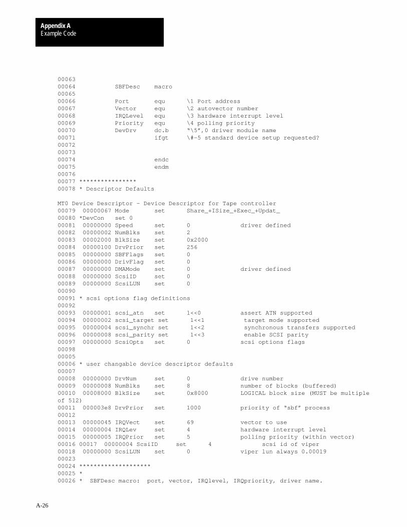
Example CodeAppendix A
A-26
00063 00064 SBFDesc macro 00065 00066 Port equ \1 Port address 00067 Vector equ \2 autovector number 00068 IRQLevel equ \3 hardware interrupt level 00069 Priority equ \4 polling priority 00070 DevDrv dc.b “\5”,0 driver module name 00071 ifgt \#–5 standard device setup requested? 00072 00073 00074 endc 00075 endm 00076 00077 ****************00078 * Descriptor Defaults
MT0 Device Descriptor – Device Descriptor for Tape controller00079 00000067 Mode set Share_+ISize_+Exec_+Updat_ 00080 *DevCon set 000081 00000000 Speed set 0 driver defined00082 00000002 NumBlks set 2 00083 00002000 BlkSize set 0x2000 00084 00000100 DrvPrior set 256 00085 00000000 SBFFlags set 0 00086 00000000 DrivFlag set 0 00087 00000000 DMAMode set 0 driver defined00088 00000000 ScsiID set 0 00089 00000000 ScsiLUN set 0 00090 00091 * scsi options flag definitions00092 00093 00000001 scsi_atn set 1<<0 assert ATN supported00094 00000002 scsi_target set 1<<1 target mode supported00095 00000004 scsi_synchr set 1<<2 synchronous transfers supported00096 00000008 scsi_parity set 1<<3 enable SCSI parity00097 00000000 ScsiOpts set 0 scsi options flags00098 00005 00006 * user changable device descriptor defaults00007 00008 00000000 DrvNum set 0 drive number00009 00000008 NumBlks set 8 number of blocks (buffered)00010 00008000 BlkSize set 0x8000 LOGICAL block size (MUST be multipleof 512)00011 000003e8 DrvPrior set 1000 priority of “sbf” process00012 00013 00000045 IRQVect set 69 vector to use00014 00000004 IRQLev set 4 hardware interrupt level00015 00000005 IRQPrior set 5 polling priority (within vector)00016 00017 00000004 ScsiID set 4 scsi id of viper00018 00000000 ScsiLUN set 0 viper lun always 0.00019 00023 00024 ********************00025 *00026 * SBFDesc macro: port, vector, IRQlevel, IRQpriority, driver name.
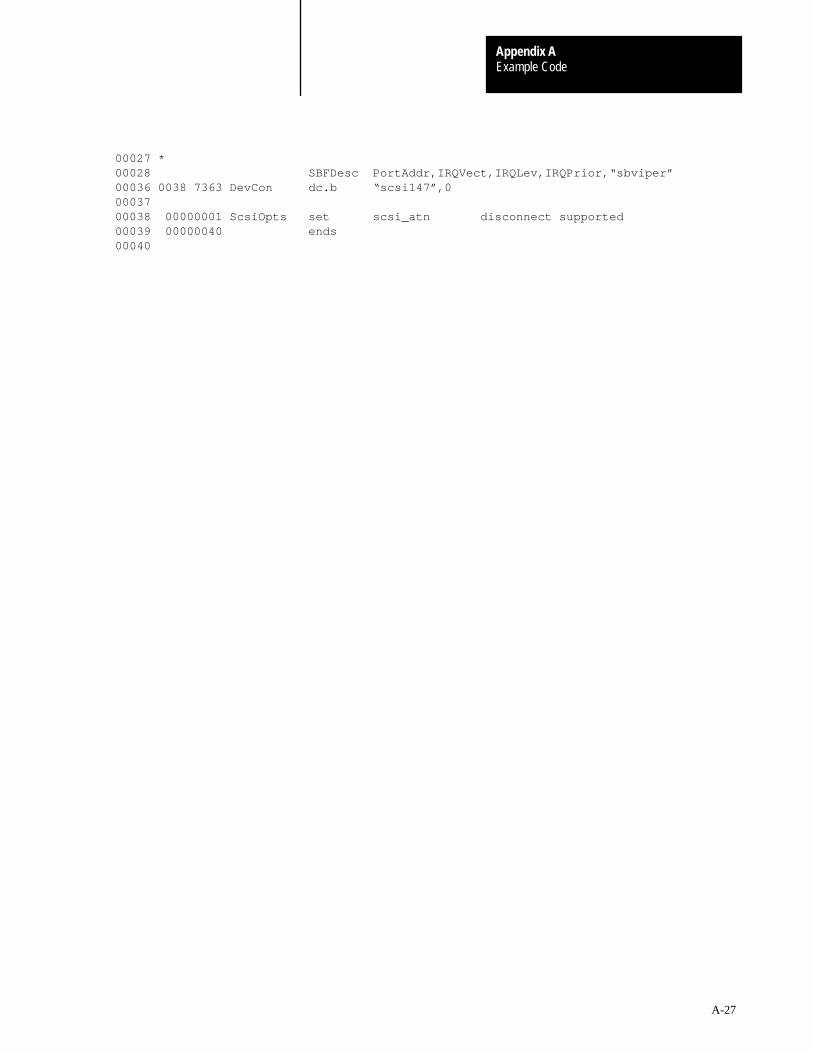
Example CodeAppendix A
A-27
00027 *00028 SBFDesc PortAddr,IRQVect,IRQLev,IRQPrior,“sbviper” 00036 0038 7363 DevCon dc.b “scsi147”,0 00037 00038 00000001 ScsiOpts set scsi_atn disconnect supported00039 00000040 ends 00040

Appendix
B
B-1
Path Descriptors and Device Descriptors
This appendix includes the device descriptor initialization table definitionsand path descriptor option tables for RBF, SCF, SBF, and PIPEMAN typedevices. Refer to Appendix A for RBF, SCF, and SBF exampledevice descriptors.
This section describes the definitions of the initialization table contained indevice descriptor modules for RBF-type devices. The table immediatelyfollows the standard device descriptor module header fields (see Chapter 3for full descriptions). Figure B.1 shows a graphic representation of thetable. The size of the table is defined in the M$Opt field.
Name: Description:
PD_DTP Device typeThis field is set to one for RBF devices. (0=SCF, 1=RBF, 2=PIPE, 3=SBF,4=NET)
PD_DRV Drive numberUse this field to associate a one-byte logical integer with each drive that adriver/controller handles. Number each controller’s drives 0 to n–1 (n isthe maximum number of drives the controller can handle and is set intoV_NDRV by the driver’s INIT routine). This number defines which drivetable the driver and RBF access for this device. RBF uses this number toset up the drive table pointer (PD_DTB). Prior to initializing PD_DTB, RBFverifies that PD_DRV is valid for the driver by checking for a value lessthan V_NDRV in the driver’s static storage. If not valid, RBF aborts thepath open and returns an error. On simple hardware, this logical drivenumber is often the same as the physical drive number.
PD_STP Step rateThis field contains a code that sets the drive’s head-stepping rate. Toreduce access time, set the step rate to the fastest value of which thedrive is capable. For floppy disks, the following codes are commonly used:
Step Code 5” Disks 8” Disks
0 30ms 15ms 1 20ms 10ms 2 12ms 6ms 3 6ms 3ms
For hard disks, the value in this field is usually driver dependent.
Introduction
RBF Device DescriptorModules
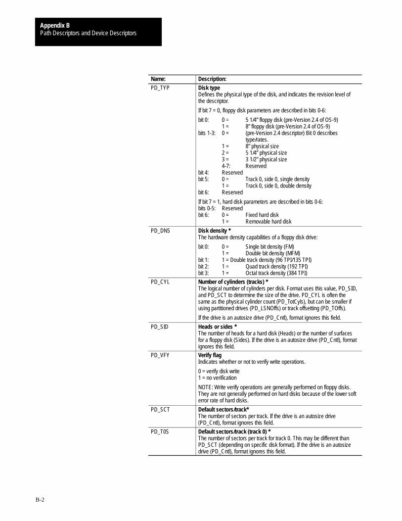
Path Descriptors and Device DescriptorsAppendix B
B-2
Name: Description:
PD_TYP Disk typeDefines the physical type of the disk, and indicates the revision level ofthe descriptor.
If bit 7 = 0, floppy disk parameters are described in bits 0-6:
bit 0: 0 = 5 1/4” floppy disk (pre-Version 2.4 of OS-9) 1 = 8” floppy disk (pre-Version 2.4 of OS-9)bits 1-3: 0 = (pre-Version 2.4 descriptor) Bit 0 describes
type/rates.1 = 8” physical size2 = 5 1/4” physical size3 = 3 1/2” physical size4-7: Reserved
bit 4: Reservedbit 5: 0 = Track 0, side 0, single density
1 = Track 0, side 0, double densitybit 6: Reserved
If bit 7 = 1, hard disk parameters are described in bits 0-6:bits 0-5: Reservedbit 6: 0 = Fixed hard disk
1 = Removable hard disk
PD_DNS Disk density *The hardware density capabilities of a floppy disk drive:
bit 0: 0 = Single bit density (FM) 1 = Double bit density (MFM)bit 1: 1 = Double track density (96 TPI/135 TPI)bit 2: 1 = Quad track density (192 TPI)bit 3: 1 = Octal track density (384 TPI)
PD_CYL Number of cylinders (tracks) * The logical number of cylinders per disk. Format uses this value, PD_SID,and PD_SCT to determine the size of the drive. PD_CYL is often thesame as the physical cylinder count (PD_TotCyls), but can be smaller ifusing partitioned drives (PD_LSNOffs) or track offsetting (PD_TOffs).
If the drive is an autosize drive (PD_Cntl), format ignores this field.
PD_SID Heads or sides *The number of heads for a hard disk (Heads) or the number of surfacesfor a floppy disk (Sides). If the drive is an autosize drive (PD_Cntl), formatignores this field.
PD_VFY Verify flagIndicates whether or not to verify write operations.
0 = verify disk write 1 = no verification
NOTE: Write verify operations are generally performed on floppy disks.They are not generally performed on hard disks because of the lower softerror rate of hard disks.
PD_SCT Default sectors/track* The number of sectors per track. If the drive is an autosize drive(PD_Cntl), format ignores this field.
PD_T0S Default sectors/track (track 0) *The number of sectors per track for track 0. This may be different thanPD_SCT (depending on specific disk format). If the drive is an autosizedrive (PD_Cntl), format ignores this field.

Path Descriptors and Device DescriptorsAppendix B
B-3
Name: Description:
PD_SAS Segment allocation sizeThe default minimum number of sectors to be allocated when a file isexpanded. Typically, this is set to the number of sectors on the mediatrack (for example, 8 for floppy disks, 32 for hard disks), but can beadjusted to suit the requirements of the system.
PD_ILV Sector interleave factor *The sequential arrangement of sectors on a disk (for example, 1, 2, 3... or1, 3, 5...). For example, if the interleave factor is 2, the sectors arearranged by 2’s (1, 3, 5...) starting at the base sector (see PD_SOffs).
NOTE: Optimized interleaving can drastically improve I/O throughput.
NOTE: PD_ILV is typically only used when the media is formatted, asformat uses this field to determine the default interleave. However, whenthe media format occurs (I$SetStat, SS_WTrk call), the desired interleaveis passed in the parameters of the call.
PD_TFM DMA (Direct Memory Access) transfer modeThe mode of transfer for DMA access, if the driver is capable of handlingdifferent DMA modes. Use of this field is driver dependent.
PD_TOffs Track base offset *The offset to the first accessible physical track number. Track 0 is notalways used as the base track because it is often a different density.
PD_SOffs Sector base offset *The offset to the first accessible physical sector number on a track. Sector0 is not always the base sector.
PD_SSize Sector sizeIndicates the physical sector size in bytes. The default sector size is 256.Depending upon whether the driver supports non-256 byte logical sectorsizes (that is, a variable sector size driver), the field is used as follows:• Variable sector size driver
If the driver supports variable logical sector sizes, RBF inspects thisvalue during a path open (specifically, after the driver returns “no error”on the SS_VarSect GetStat call) and uses this value as the logicalsector size of the media. This value is then copied into PD_SctSiz ofthe path descriptor options section, so that application programs canknow the logical sector size of the media, if required. RBF supportslogical sector sizes from 256 bytes to 32,768 bytes, in integral binarymultiples (256, 512, 1024, etc.).
During the SS_VarSect call, the driver can validate or update this field(or the media itself) according to the driver’s conventions. Thesetypically are:
• If the driver can dynamically determine the media’s sector size, andPD_SSize is passed in as 0, the driver updates this field according tothe current media setting.
• If the driver can dynamically set the media’s sector size, and PD_SSizeis passed in as a non-zero value, the driver sets the media to the valuein PD_SSize (this is typical when re-formatting the media).
• If the driver cannot dynamically determine or set the media sector size,it usually validates PD_SSize against the supported sector sizes, andreturns an error (E$SectSiz) if PD_SSize contains an invalid value.
• Non-variable sector size driverIf the driver does not support variable logical sector sizes (that is,logical sector size is fixed at 256 bytes), RBF ignores PD_SSize. In thiscase, PD_SSize can be used to support deblocking drivers that supportvarious physical sector sizes.
NOTE: A non-variable sector sized driver is defined as a driver whichreturns the E$UnkSvc error for GetStat (SS_VarSect).

Path Descriptors and Device DescriptorsAppendix B
B-4
Name: Description:
PD_Cntl Device control wordIndicates options that reflect the capabilities of the device. You may setthese options, as follows:
bit 0: 0 = Format enable 1 = Format inhibitbit 1: 0 = Single-Sector I/O 1 = Multi-Sector I/O capablebit 2: 0 = Device has non-stable ID 1 = Device has stable IDbit 3: 0 = Device size determined from descriptor values 1 = Device size obtained by SS_DSize GetStat callbit 4: 0 = Device cannot format a single track 1 = Device can format a single trackbits 5-15: Reserved
PD_Trys Number of triesIndicates whether a driver should try to access the disk again beforereturning an error. Depending upon the driver in use, this field may beimplemented as a flag or a retry counter:
Value Flag Counter 0 retry ON default number of retries1 retry OFF no retriesother retry ON specified number of retries
Drivers that work with controllers that have error correcting functions (forexample, E.C.C. on hard disks) should treat this field as a flag so they canset the controller’s error correction/retry functions accordingly.
When formatting media, especially hard disks, the format-enableddescriptor should set this field to one (retry OFF) to ensure that marginalmedia sections are marked out of the media free space.
PD_LUN Logical unit number of SCSI driveUsed in the SCSI command block to identify the logical unit on the SCSIcontroller. To eliminate allocation of unused drive tables in the driver staticstorage, this number may be different from PD_DRV. PD_DRV indicatesthe logical number of the drive to the driver, that is, the drive table to use.PD_LUN is the physical drive number on the controller.
PD_WPC First cylinder to use write precompensationThe cylinder to begin write precompensation.
PD_RWR First cylinder to use reduced write currentThe cylinder to begin reduced write current.
PD_Park Cylinder used to park headThe cylinder at which to park the hard disk’s head when the drive is shutdown. Parking is usually done on hard disks when they are shipped ormoved and is implemented by the SS_SQD SetStat to the driver.
PD_LSNOffs Logical sector offsetThe offset to use when accessing a partitioned drive. The driver adds thisvalue to the logical block address passed by RBF prior to determining thephysical block address on the media. Typically, using PD_LSNOffs ismutually exclusive to using PD_TOffs.
PD_TotCyls Total cylinders on deviceThe actual number of physical cylinders on a drive. It is used by the driverto correctly initialize the controller/drive. PD_TotCyls is typically used forphysical initialization of a drive that is partitioned or has PD_TOffs set to anon-zero value. In this case, PD_CYL denotes the logical number ofcylinders of the drive. If PD_TotCyls is zero, the driver should determinethe physical cylinder count by using the sum of PD_CYL and PD_TOffs.
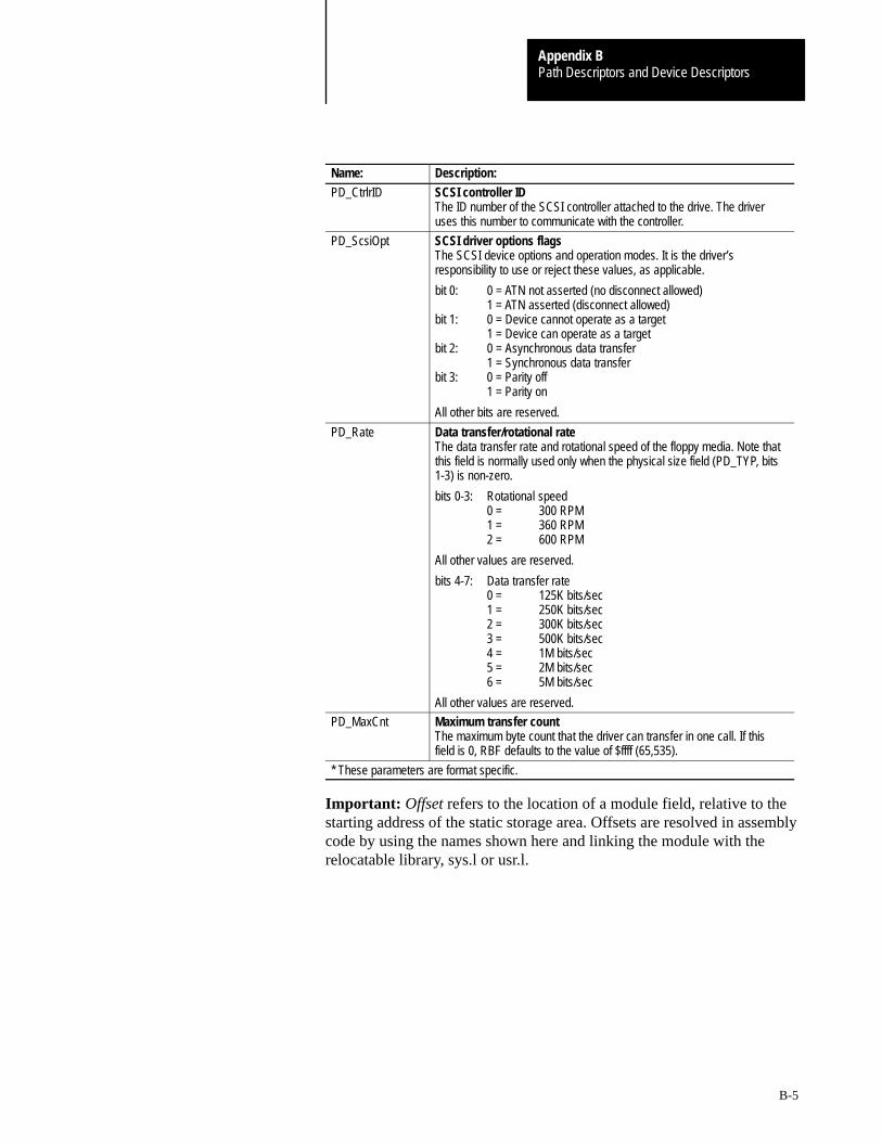
Path Descriptors and Device DescriptorsAppendix B
B-5
Name: Description:
PD_CtrlrID SCSI controller IDThe ID number of the SCSI controller attached to the drive. The driveruses this number to communicate with the controller.
PD_ScsiOpt SCSI driver options flagsThe SCSI device options and operation modes. It is the driver’sresponsibility to use or reject these values, as applicable.
bit 0: 0 = ATN not asserted (no disconnect allowed)1 = ATN asserted (disconnect allowed)
bit 1: 0 = Device cannot operate as a target1 = Device can operate as a target
bit 2: 0 = Asynchronous data transfer1 = Synchronous data transfer
bit 3: 0 = Parity off1 = Parity on
All other bits are reserved.
PD_Rate Data transfer/rotational rateThe data transfer rate and rotational speed of the floppy media. Note thatthis field is normally used only when the physical size field (PD_TYP, bits1-3) is non-zero.
bits 0-3: Rotational speed0 = 300 RPM1 = 360 RPM2 = 600 RPM
All other values are reserved.
bits 4-7: Data transfer rate0 = 125K bits/sec1 = 250K bits/sec2 = 300K bits/sec3 = 500K bits/sec4 = 1M bits/sec5 = 2M bits/sec6 = 5M bits/sec
All other values are reserved.
PD_MaxCnt Maximum transfer countThe maximum byte count that the driver can transfer in one call. If thisfield is 0, RBF defaults to the value of $ffff (65,535).
* These parameters are format specific.
Important: Offset refers to the location of a module field, relative to thestarting address of the static storage area. Offsets are resolved in assemblycode by using the names shown here and linking the module with therelocatable library, sys.l or usr.l.
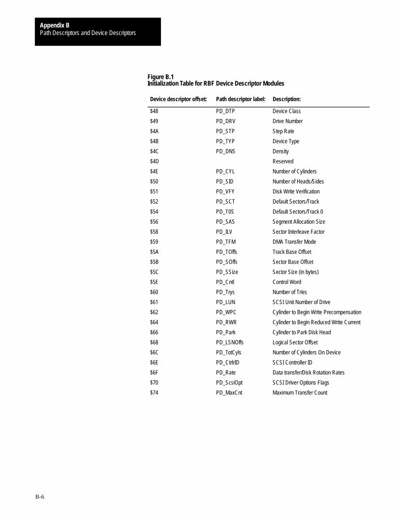
Path Descriptors and Device DescriptorsAppendix B
B-6
Figure B.1Initialization Table for RBF Device Descriptor Modules
Device descriptor offset: Path descriptor label: Description:
$48 PD_DTP Device Class
$49 PD_DRV Drive Number
$4A PD_STP Step Rate
$4B PD_TYP Device Type
$4C PD_DNS Density
$4D Reserved
$4E PD_CYL Number of Cylinders
$50 PD_SID Number of Heads/Sides
$51 PD_VFY Disk Write Verification
$52 PD_SCT Default Sectors/Track
$54 PD_T0S Default Sectors/Track 0
$56 PD_SAS Segment Allocation Size
$58 PD_ILV Sector Interleave Factor
$59 PD_TFM DMA Transfer Mode
$5A PD_TOffs Track Base Offset
$5B PD_SOffs Sector Base Offset
$5C PD_SSize Sector Size (in bytes)
$5E PD_Cntl Control Word
$60 PD_Trys Number of Tries
$61 PD_LUN SCSI Unit Number of Drive
$62 PD_WPC Cylinder to Begin Write Precompensation
$64 PD_RWR Cylinder to Begin Reduced Write Current
$66 PD_Park Cylinder to Park Disk Head
$68 PD_LSNOffs Logical Sector Offset
$6C PD_TotCyls Number of Cylinders On Device
$6E PD_CtrlrID SCSI Controller ID
$6F PD_Rate Data transfer/Disk Rotation Rates
$70 PD_ScsiOpt SCSI Driver Options Flags
$74 PD_MaxCnt Maximum Transfer Count

Path Descriptors and Device DescriptorsAppendix B
B-7
The first 26 fields of the path options section (PD_OPT) of the RBF pathdescriptor are copied directly from the device descriptor standardinitialization table. All of the values in this table may be examined usingI$GetStt by applications using the SS_Opt code. Some of the values maybe changed using I$SetStt; some are protected by the file manager toprevent inappropriate changes. You can update the following fields usingGetStat and SetStat system calls:
PD_STP PD_TYP PD_DNSPD_CYL PD_SID PD_VFYPD_SCT PD_TOS PD_SAS
All other fields are read-only. The RBF path descriptor option table isshown on the following page.
Refer to the previous section on RBF device descriptors for descriptions ofthe first 26 fields. The last five fields contain information providedby RBF:
Name: Description:
PD_ATT File attributes (D S PE PW PR E W R)The file’s attributes are defined as follows:
bit 0: Set if owner read.bit 1: Set if owner write.bit 2: Set if owner execute.bit 3: Set if public read.bit 4: Set if public write.bit 5: Set if public execute.bit 6: Set if only one user at a time can open the file.bit 7: Set if directory file.
PD_FD File descriptor The LSN (Logical Sector Number) of the file’s file descriptor is writtenhere.
PD_DFD Directory file descriptor The LSN of the file’s directory file descriptor is written here.
PD_DCP File’s directory entry pointerThe current position of the file’s entry in its directory.
PD_DVT Device table pointer (copy)The address of the device table entry associated with the path.
PD_SctSiz Logical sector sizeThe logical sector size of the device associated with the path. If this is 0,assume a size of 256 bytes.
PD_NAME File name
Important: In the following chart, offset refers to the location of a pathdescriptor field relative to the starting address of the path descriptor. Pathdescriptor offsets are resolved in assembly code by using the names shownhere and linking with the relocatable library: sys.l or usr.l.
RBF Definitions of the PathDescriptor

Path Descriptors and Device DescriptorsAppendix B
B-8
Figure B.2Option Table for RBF Path Descriptor
Offset: Name: Description:
$80 PD_DTP Device Class
$81 PD_DRV Drive Number
$82 PD_STP Step Rate
$83 PD_TYP Device Type
$84 PD_DNS Density
$85 Reserved
$86 PD_CYL Number of Cylinders
$88 PD_SID Number of Heads/Sides
$89 PD_VFY Disk Write Verification
$8A PD_SCT Default Sectors/Track
$8C PD_TOS Default Sectors/Track 0
$8E PD_SAS Segment Allocation Size
$90 PD_ILV Sector Interleave Factor
$91 PD_TFM DMA Transfer Mode
$92 PD_TOffs Track Base Offset
$93 PD_SOffs Sector Base Offset
$94 PD_SSize Sector Size (in bytes)
$96 PD_Cntl Control Word
$98 PD_Trys Number of Tries
$99 PD_LUN SCSI Unit Number of Drive
$9A PD_WPC Cylinder to Begin Write Precompensation
$9C PD_RWR Cylinder to Begin Reduced Write Current
$9E PD_Park Cylinder to Park Disk Head
$A0 PD_LSNOffs Logical Sector Offset
$A4 PD_TotCyls Number of Cylinders On Device
$A6 PD_CtrlrID SCSI Controller ID
$A7 PD_Rate Data Transfer/Rotational Rates
$A8 PD_ScsiOpt SCSI Driver Option Flag
$AC PD_MaxCnt Maximum Transfer Count
$B0 Reserved
$B5 PD_ATT File Attributes
$B6 PD_FD File Descriptor
$BA PD_DFD Directory File Descriptor
$BE PD_DCP File’s Directory Entry Pointer
$C2 PD_DVT Device Table Pointer (copy)
$C6 Reserved
$C8 PD_SctSiz Logical Sector Size
$CC Reserved
$E0 PD_NAME File Name

Path Descriptors and Device DescriptorsAppendix B
B-9
Device descriptor modules for SCF-type devices contain the deviceaddress and an initialization table which defines initial values for the I/Oediting features, as listed below. The initialization table immediatelyfollows the standard device descriptor module header fields (see Chapter 3for full descriptions). The size of the table is defined in the M$Opt field.The initialization table is graphically shown in Figure B.3 and thefollowing table.
Important: You can change or disable most of these special editingfunctions by changing the corresponding control character in the pathdescriptor. You can do this with the I$SetStt service request or the tmodeutility. A permanent solution may be to change the corresponding controlcharacter value in the device descriptor module. You can easily change thedevice descriptors with the xmode utility.
Name: Description:
PD_DTP Device typeSet to zero for SCF devices. (0=SCF, 1=RBF, 2=PIPE, 3=SBF, 4=NET)
PD_UPC Letter caseIf PD_UPC is not equal to zero, input or output characters in the range“a..z” are made “A..Z”.
PD_BSO Destructive backspaceIf PD_BSO is zero when a backspace character is input, SCF echoesPD_BSE (backspace echo character). If PD_BSO is non-zero, SCFechoes PD_BSE, space, PD_BSE.
PD_DLO DeleteIf PD_DLO is zero, SCF deletes by backspace-erasing over the line. IfPD_DLO is not zero, SCF deletes by echoing a carriage return/line-feed.
PD_EKO EchoIf PD_EKO is not zero, all input bytes are echoed, except undefinedcontrol characters, which are printed as periods. If PD_EKO is zero, inputcharacters are not echoed.
PD_ALF Automatic line feedIf PD_ALF is not zero, line-feeds automatically follow carriage returns.
PD_NUL End of line null countIndicates the number of NULL padding bytes to send after a carriagereturn/line-feed character.
PD_PAU End of page pauseIf PD_PAU is not zero, an auto page pause occurs upon reaching a fullscreen of output. See PD_PAG for setting page length.
PD_PAG Page lengthContains the number of lines per screen (or page).
PD_BSP Backspace “input” characterIndicates the input character recognized as backspace. See PD_BSE andPD_BSO.
PD_DEL Delete line characterIndicates the input character recognized as the delete line function. SeePD_DLO.
SCF Device DescriptorModules

Path Descriptors and Device DescriptorsAppendix B
B-10
Name: Description:
PD_EOR End of record characterDefines the last character on each line entered (I$Read, I$ReadLn). Anoutput line is terminated (I$Writln) when this character is sent. NormallyPD_EOR should be set to $0D.
WARNING: If PD_EOR is set to zero, SCF’s I$ReadLn will neverterminate, unless an EOF or error occurs.
PD_EOF End of file characterThis field defines the end-of-file character. SCF returns an end-of-file erroron I$Read or I$ReadLn if this is the first (and only) character input.
PD_RPR Reprint line characterIf this character is input, SCF (I$ReadLn) reprints the current input line. Acarriage return is also inserted in the input buffer for PD_DUP (see below)to make correcting typing errors more convenient.
PD_DUP Duplicate last line characterIf this character is input, SCF (I$ReadLn) duplicates whatever is in theinput buffer through the first PD_EOR character. Normally, this is theprevious line typed.
PD_PSC Pause characterIf this character is typed during output, output is suspended before thenext end-of-line. This also deletes any “type ahead” input for I$ReadLn.
PD_INT Keyboard interrupt characterIf this character is input, SCF sends a keyboard interrupt signal to the lastuser of this path. It terminates the current I/O request (if any) with an erroridentical to the keyboard interrupt signal code. PD_INT is normally set to acontrol-C character.
PD_QUT Keyboard abort characterIf this character is input, SCF sends a keyboard abort signal to the lastuser of this path. It terminates the current I/O request (if any) with an errorcode identical to the keyboard abort signal code. PD_QUT is normally setto a control-E character.
PD_BSE Backspace “output” character (echo character)This field indicates the backspace character to echo when PD_BSP isinput. See PD_BSP and PD_BSO.
PD_OVF Line overflow characterIf I$ReadLn has satisfied its input byte count, SCF ignores any furtherinput characters until an end-of-record character (PD_EOR) is received. Itechoes the PD_OVF character for each byte ignored. PD_OVF is usuallyset to the terminal’s bell character.
PD_PAR Parity code, number of stop bits and bits/character Bits zero and one indicate the parity as follows:
0 = no parity 1 = odd parity 3 = even parity
Bits two and three indicate the number of bits per character as follows:
0 = 8 bits/character1 = 7 bits/character 2 = 6 bits/character 3 = 5 bits/character
Bits four and five indicate the number of stop bits as follows:
0 = 1 stop bit 1 = 1 1/2 stop bits 2 = 2 stop bits
Bits six and seven are reserved.
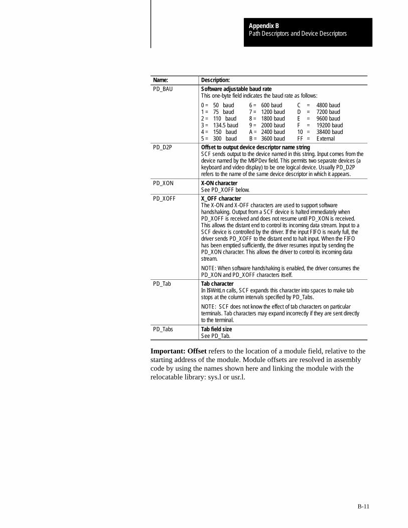
Path Descriptors and Device DescriptorsAppendix B
B-11
Name: Description:
PD_BAU Software adjustable baud rateThis one-byte field indicates the baud rate as follows:
0 = 50 baud 6 = 600 baud C = 4800 baud 1 = 75 baud 7 = 1200 baud D = 7200 baud 2 = 110 baud 8 = 1800 baud E = 9600 baud 3 = 134.5 baud 9 = 2000 baud F = 19200 baud 4 = 150 baud A = 2400 baud 10 = 38400 baud5 = 300 baud B = 3600 baud FF = External
PD_D2P Offset to output device descriptor name stringSCF sends output to the device named in this string. Input comes from thedevice named by the M$PDev field. This permits two separate devices (akeyboard and video display) to be one logical device. Usually PD_D2Prefers to the name of the same device descriptor in which it appears.
PD_XON X-ON characterSee PD_XOFF below.
PD_XOFF X_OFF characterThe X-ON and X-OFF characters are used to support softwarehandshaking. Output from a SCF device is halted immediately whenPD_XOFF is received and does not resume until PD_XON is received.This allows the distant end to control its incoming data stream. Input to aSCF device is controlled by the driver. If the input FIFO is nearly full, thedriver sends PD_XOFF to the distant end to halt input. When the FIFOhas been emptied sufficiently, the driver resumes input by sending thePD_XON character. This allows the driver to control its incoming datastream.
NOTE: When software handshaking is enabled, the driver consumes thePD_XON and PD_XOFF characters itself.
PD_Tab Tab characterIn I$WritLn calls, SCF expands this character into spaces to make tabstops at the column intervals specified by PD_Tabs.
NOTE: SCF does not know the effect of tab characters on particularterminals. Tab characters may expand incorrectly if they are sent directlyto the terminal.
PD_Tabs Tab field sizeSee PD_Tab.
Important: Offset refers to the location of a module field, relative to thestarting address of the module. Module offsets are resolved in assemblycode by using the names shown here and linking the module with therelocatable library: sys.l or usr.l.

Path Descriptors and Device DescriptorsAppendix B
B-12
Figure B.3Device Descriptor Initialization Table
Device descriptor offset: Path descriptor label: Description:
$48 PD_DTP Device Type
$49 PD_UPC Upper Case Lock
$4A PD_BSO Backspace Option
$4B PD_DLO Delete Line Character
$4C PD_EKO Echo
$4D PD_ALF Automatic Line Feed
$4E PD_NUL End Of Line Null Count
$4F PD_PAU End Of Page Pause
$50 PD_PAG Page Length
$51 PD_BSP Backspace Input Character
$52 PD_DEL Delete Line Character
$53 PD_EOR End Of Record Character
$54 PD_EOF End Of File Character
$55 PD_RPR Reprint Line Character
$56 PD_DUP Duplicate Line Character
$57 PD_PSC Pause Character
$58 PD_INT Keyboard Interrupt Character
$59 PD_QUT Keyboard Abort Character
$5A PD_BSE Backspace Output
$5B PD_OVF Line Overflow Character (bell)
$5C PD_PAR Parity Code, # of Stop Bits, and # ofBits/Character
$5D PD_BAU Adjustable Baud Rate
$5E PD_D2P Offset To Output Device Name
$60 PD_XON X-ON Character
$61 PD_XOFF X-OFF Character
$62 PD_TAB Tab Character
$63 PD_TABS Tab Column Width
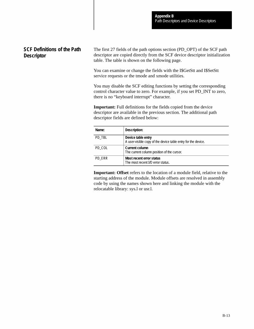
Path Descriptors and Device DescriptorsAppendix B
B-13
The first 27 fields of the path options section (PD_OPT) of the SCF pathdescriptor are copied directly from the SCF device descriptor initializationtable. The table is shown on the following page.
You can examine or change the fields with the I$GetStt and I$SetSttservice requests or the tmode and xmode utilities.
You may disable the SCF editing functions by setting the correspondingcontrol character value to zero. For example, if you set PD_INT to zero,there is no “keyboard interrupt” character.
Important: Full definitions for the fields copied from the devicedescriptor are available in the previous section. The additional pathdescriptor fields are defined below:
Name: Description:
PD_TBL Device table entryA user-visible copy of the device table entry for the device.
PD_COL Current columnThe current column position of the cursor.
PD_ERR Most recent error statusThe most recent I/O error status.
Important: Offset refers to the location of a module field, relative to thestarting address of the module. Module offsets are resolved in assemblycode by using the names shown here and linking the module with therelocatable library: sys.l or usr.l.
SCF Definitions of the PathDescriptor
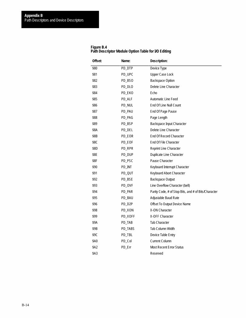
Path Descriptors and Device DescriptorsAppendix B
B-14
Figure B.4Path Descriptor Module Option Table for I/O Editing
Offset: Name: Description:
$80 PD_DTP Device Type
$81 PD_UPC Upper Case Lock
$82 PD_BSO Backspace Option
$83 PD_DLO Delete Line Character
$84 PD_EKO Echo
$85 PD_ALF Automatic Line Feed
$86 PD_NUL End Of Line Null Count
$87 PD_PAU End Of Page Pause
$88 PD_PAG Page Length
$89 PD_BSP Backspace Input Character
$8A PD_DEL Delete Line Character
$8B PD_EOR End Of Record Character
$8C PD_EOF End Of File Character
$8D PD_RPR Reprint Line Character
$8E PD_DUP Duplicate Line Character
$8F PD_PSC Pause Character
$90 PD_INT Keyboard Interrupt Character
$91 PD_QUT Keyboard Abort Character
$92 PD_BSE Backspace Output
$93 PD_OVF Line Overflow Character (bell)
$94 PD_PAR Parity Code, # of Stop Bits, and # of Bits/Character
$95 PD_BAU Adjustable Baud Rate
$96 PD_D2P Offset To Output Device Name
$98 PD_XON X-ON Character
$99 PD_XOFF X-OFF Character
$9A PD_TAB Tab Character
$9B PD_TABS Tab Column Width
$9C PD_TBL Device Table Entry
$A0 PD_Col Current Column
$A2 PD_Err Most Recent Error Status
$A3 Reserved
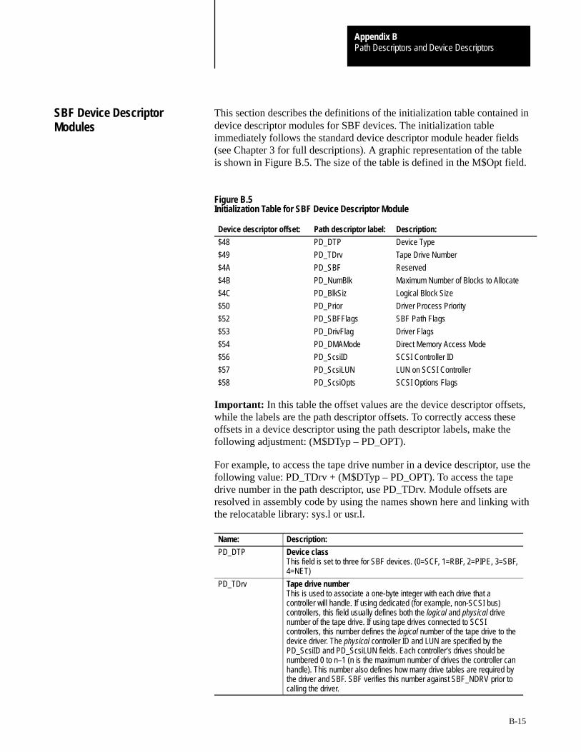
Path Descriptors and Device DescriptorsAppendix B
B-15
This section describes the definitions of the initialization table contained indevice descriptor modules for SBF devices. The initialization tableimmediately follows the standard device descriptor module header fields(see Chapter 3 for full descriptions). A graphic representation of the tableis shown in Figure B.5. The size of the table is defined in the M$Opt field.
Figure B.5Initialization Table for SBF Device Descriptor Module
Device descriptor offset: Path descriptor label: Description:
$48 PD_DTP Device Type
$49 PD_TDrv Tape Drive Number
$4A PD_SBF Reserved
$4B PD_NumBlk Maximum Number of Blocks to Allocate
$4C PD_BlkSiz Logical Block Size
$50 PD_Prior Driver Process Priority
$52 PD_SBFFlags SBF Path Flags
$53 PD_DrivFlag Driver Flags
$54 PD_DMAMode Direct Memory Access Mode
$56 PD_ScsiID SCSI Controller ID
$57 PD_ScsiLUN LUN on SCSI Controller
$58 PD_ScsiOpts SCSI Options Flags
Important: In this table the offset values are the device descriptor offsets,while the labels are the path descriptor offsets. To correctly access theseoffsets in a device descriptor using the path descriptor labels, make thefollowing adjustment: (M$DTyp – PD_OPT).
For example, to access the tape drive number in a device descriptor, use thefollowing value: PD_TDrv + (M$DTyp – PD_OPT). To access the tapedrive number in the path descriptor, use PD_TDrv. Module offsets areresolved in assembly code by using the names shown here and linking withthe relocatable library: sys.l or usr.l.
Name: Description:
PD_DTP Device classThis field is set to three for SBF devices. (0=SCF, 1=RBF, 2=PIPE, 3=SBF,4=NET)
PD_TDrv Tape drive numberThis is used to associate a one-byte integer with each drive that acontroller will handle. If using dedicated (for example, non-SCSI bus)controllers, this field usually defines both the logical and physical drivenumber of the tape drive. If using tape drives connected to SCSIcontrollers, this number defines the logical number of the tape drive to thedevice driver. The physical controller ID and LUN are specified by thePD_ScsiID and PD_ScsiLUN fields. Each controller’s drives should benumbered 0 to n–1 (n is the maximum number of drives the controller canhandle). This number also defines how many drive tables are required bythe driver and SBF. SBF verifies this number against SBF_NDRV prior tocalling the driver.
SBF Device DescriptorModules

Path Descriptors and Device DescriptorsAppendix B
B-16
Name: Description:
PD_NumBlk Number of buffers/blocks used for bufferingSpecifies the maximum number of buffers to be allocated by SBF for useby the auxiliary process in buffered I/O. If this field is set to 0, unbufferedI/O is specified.
PD_BlkSiz Logical block size used for I/OSpecifies the size of the buffer to be allocated by SBF. This buffer size isused when allocating multiple buffers used in buffered I/O. Unless thedriver manages partial physical blocks, this size should be an integermultiple of the physical tape block size.
PD_Prior Driver process priorityThe priority at which SBF’s auxiliary process will run. This value is usedduring initialization. Changing this value after initialization has no effect.
PD_SBFFlags SBF path flagsSpecifies the actions that SBF takes when the path is closed. You canupdate this field using GetStat/SetStat (SS_Opt). SBF supports thefollowing flag definitions:
bit 0: (f_rest_b) 0 = No rewind on close.1 = Rewind on close.
bit 1: (f_offl_b) 0 = Do not put drive off-line on close.1 = Put drive off-line on close.
bit 2: (f_eras_b) 0 = Do not erase to end-of-tape on close.1 = Erase to end-of-tape on close.
PD_DrivFlag Driver flagsThis field is available for use by the device driver.
NOTE: References to these flags are often made using the PD_Flagsoffset (defined in sys.l and usr.l). This reference is equivalent toPD_SBFFlags. References to PD_DrivFlag should use a value ofPD_Flags + 1.
PD_DMAMode Direct memory access modeThis field is hardware specific. If available, you can use this word tospecify the DMA Mode of the driver.
PD_ScsiID SCSI controller IDThis is the ID number of the SCSI controller attached to the device. Thedriver uses this number when communicating with the controller.
PD_ScsiLUN Logical unit number of SCSI deviceThis number is the value to use in the SCSI command block to identify thelogical unit on the SCSI controller. This number may be different fromPD_TDrv to eliminate allocation of unused drive table storage. PD_TDrvindicates the logical number of the drive to the driver and SBF (drive tableto use). PD_ScsiLUN is the physical drive number on the controller.
PD_ScsiOpts SCSI driver options flagsThis field allows SCSI device options and operation modes to bespecified. It is the driver’s responsibility to use or reject these if applicable:
bit 0: 0 = ATN not asserted (no disconnects allowed).1 = ATN asserted (disconnects allowed).
bit 1: 0 = Device cannot operate as a target.1 = Device can operate as a target.
bit 2: 0 = asynchronous data transfers.1 = synchronous data transfers.
bit 3: 0 = parity off.1 = parity on.
All other bits are reserved.

Path Descriptors and Device DescriptorsAppendix B
B-17
The reserved section (PD_OPT) of the path descriptor used by SBF iscopied directly from the initialization table of the device descriptor. Thefollowing table is provided to show the offsets used in the path descriptor.For a full explanation of the path descriptor fields, refer to theprevious pages.
Offset: Name: Description:
$80 PD_DTP Device Type
$81 PD_TDrv Tape Drive Number
$82 PD_SBF Reserved
$83 PD_NumBlk Maximum Number of Blocks to Allocate
$84 PD_BlkSiz Logical Block Size
$88 PD_Prior Driver Process Priority
$8A PD_SBFFlags* SBF Path Flags
$8B PD_DrivFlag* Driver Flags
$8C PD_DMAMode Direct Memory Access Mode
$8E PD_ScsiID SCSI Controller ID
$8F PD_ScsiLUN LUN on SCSI controller
$90 PD_ScsiOpts SCSI Options Flags
* References to these flags are often made using the PD_Flags offset (defined in sys.l and usr.l).This reference is equivalent to PD_SBFFlags. References to PD_DrivFlag should use a value ofPD_Flags + 1.
Important: Offset refers to the location of a path descriptor field relativeto the starting address of the path descriptor. Path descriptor offsets areresolved in assembly code by using the names shown here and linking themodule with the relocatable library: sys.l or usr.l.
SBF Definitions of the PathDescriptor
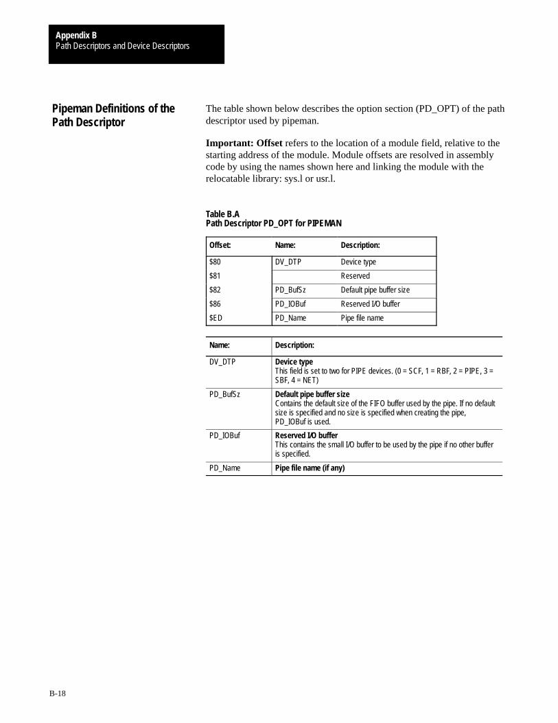
Path Descriptors and Device DescriptorsAppendix B
B-18
The table shown below describes the option section (PD_OPT) of the pathdescriptor used by pipeman.
Important: Offset refers to the location of a module field, relative to thestarting address of the module. Module offsets are resolved in assemblycode by using the names shown here and linking the module with therelocatable library: sys.l or usr.l.
Table B.APath Descriptor PD_OPT for PIPEMAN
Offset: Name: Description:
$80 DV_DTP Device type
$81 Reserved
$82 PD_BufSz Default pipe buffer size
$86 PD_IOBuf Reserved I/O buffer
$ED PD_Name Pipe file name
Name: Description:
DV_DTP Device typeThis field is set to two for PIPE devices. (0 = SCF, 1 = RBF, 2 = PIPE, 3 =SBF, 4 = NET)
PD_BufSz Default pipe buffer sizeContains the default size of the FIFO buffer used by the pipe. If no defaultsize is specified and no size is specified when creating the pipe,PD_IOBuf is used.
PD_IOBuf Reserved I/O bufferThis contains the small I/O buffer to be used by the pipe if no other bufferis specified.
PD_Name Pipe file name (if any)
Pipeman Definitions of thePath Descriptor
Appendix
C
C-1
OS-9 System Calls
You use system calls to communicate between the OS-9 operating systemand assembly language level programs. There are three general categoriesof system calls:
user-state I/O system-state
All system calls have a mnemonic name for easy reference. User andsystem state functions start with F$. I/O related functions begin with I$.The mnemonic names are defined in the relocatable library file usr.l orsys.l. You should link these files with your programs.
The OS-9 I/O system calls are simpler to use than in many other operatingsystems. This is because the calling program does not have to allocate andset up file control blocks, sector buffers, etc. Instead, OS-9 returns a pathnumber word when a file/device is opened. You can use this path numberin subsequent I/O requests to identify the file/device until the path isclosed. OS-9 internally allocates and maintains its own data structures, you never have to deal with them.
System state system calls are privileged and can only execute while OS-9 is in system state (when it is processing another service request,executing a file manager, device driver, etc.). System state functions areincluded in this manual primarily for the benefit of those programmerswho are writing device drivers and other system-level applications. For a full description of system state and its uses, refer to Chapter 2 of the OS-9 Technical Overview.
System calls are performed by loading the MPU registers with theappropriate parameters and executing a Trap #0 instruction, immediatelyfollowed by a constant word (the request code). Function results (if any)are returned in the MPU registers after OS-9 has processed the servicerequest. All system calls use a standard convention for reporting errors; if an error occurred, the carry bit of the condition code register is set and register d1.w contains an appropriate error code, permitting a BCS or BCC instruction immediately following the system call to branch on error/no error.
OS-9 System CallDescriptions
OS-9 System CallsAppendix C
C-2
Here is an example system call for the Close service request:
MOVE.W Pathnum (a6),d0
TRAP #0
DC.W I$Close
BCS.S Error
Using the assembler’s OS9 directive simplifies the call:
MOVE.W Pathnum (a6),d0
OS9 I$Close
BCS.S Error
Some system calls generate errors themselves; these are listed asPOSSIBLE ERRORS. If the returned error code does not match any of thegiven possible errors, then it was probably returned by another system callmade by the main call.
The SEE ALSO listing for each service request shows related servicerequests and/or chapters that may yield more information aboutthe request.
In the system call descriptions which follow, registers not explicitlyspecified as input or output parameters are not altered. Strings passed asparameters are normally terminated by a null byte.
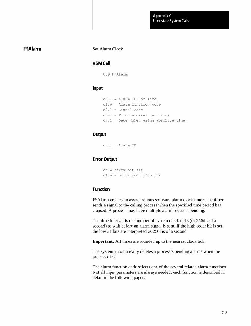
User-state System CallsAppendix C
C-3
Set Alarm Clock
ASM Call
OS9 F$Alarm
Input
d0.l = Alarm ID (or zero)
d1.w = Alarm function code
d2.l = Signal code
d3.l = Time interval (or time)
d4.l = Date (when using absolute time)
Output
d0.l = Alarm ID
Error Output
cc = carry bit set
d1.w = error code if error
Function
F$Alarm creates an asynchronous software alarm clock timer. The timersends a signal to the calling process when the specified time period haselapsed. A process may have multiple alarm requests pending.
The time interval is the number of system clock ticks (or 256ths of asecond) to wait before an alarm signal is sent. If the high order bit is set,the low 31 bits are interpreted as 256ths of a second.
Important: All times are rounded up to the nearest clock tick.
The system automatically deletes a process’s pending alarms when theprocess dies.
The alarm function code selects one of the several related alarm functions.Not all input parameters are always needed; each function is described indetail in the following pages.
F$Alarm
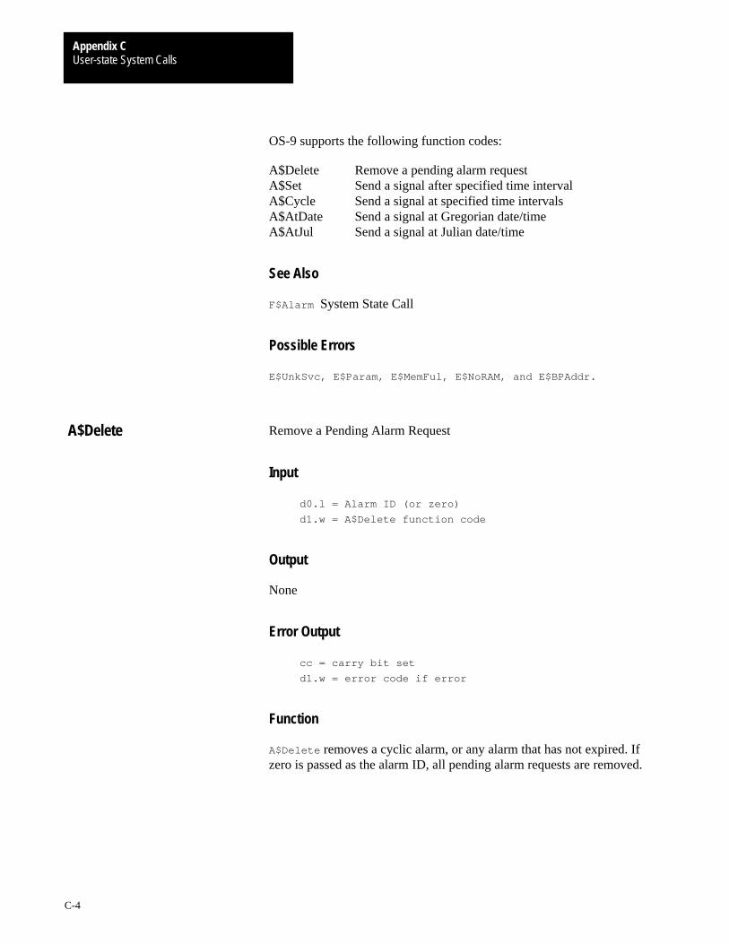
User-state System CallsAppendix C
C-4
OS-9 supports the following function codes:
A$Delete Remove a pending alarm requestA$Set Send a signal after specified time intervalA$Cycle Send a signal at specified time intervalsA$AtDate Send a signal at Gregorian date/timeA$AtJul Send a signal at Julian date/time
See Also
F$Alarm System State Call
Possible Errors
E$UnkSvc, E$Param, E$MemFul, E$NoRAM, and E$BPAddr.
Remove a Pending Alarm Request
Input
d0.l = Alarm ID (or zero)
d1.w = A$Delete function code
Output
None
Error Output
cc = carry bit set
d1.w = error code if error
Function
A$Delete removes a cyclic alarm, or any alarm that has not expired. Ifzero is passed as the alarm ID, all pending alarm requests are removed.
A$Delete

User-state System CallsAppendix C
C-5
Send a Signal After a Specified Time Interval
Input
d0.l = Reserved, must be zero
d1.w = A$Set function code
d2.w = Signal code
d3.l = Time Interval
Output
d0.l = Alarm ID
Error Output
cc = carry bit set
d1.w = error code if error
Function
A$Set sends one signal after the specified time interval has elapsed. Thetime interval may be specified in system clock ticks, or 256ths of a second.
A$Set

User-state System CallsAppendix C
C-6
Send a Signal Every N Ticks/Seconds
Input
d0.l = reserved, must be zero
d1.w = A$Cycle function code
d2.l = signal code
d3.l = time interval (N)
Output
d0.l = Alarm ID
Error Output
cc = carry bit set
d1.w = error code if error
Function
A$Cycle is similar to the A$Set function, except that the alarm is reset afterit is sent, to provide a recurring periodic signal.
A$Cycle
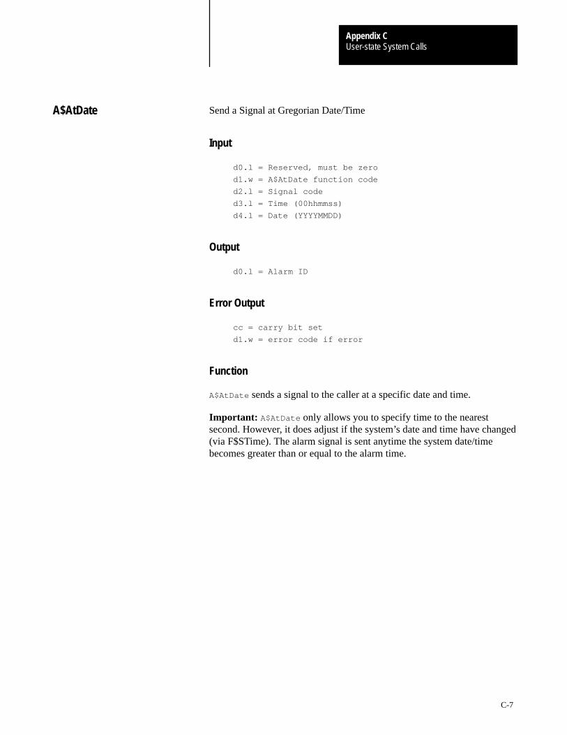
User-state System CallsAppendix C
C-7
Send a Signal at Gregorian Date/Time
Input
d0.l = Reserved, must be zero
d1.w = A$AtDate function code
d2.l = Signal code
d3.l = Time (00hhmmss)
d4.l = Date (YYYYMMDD)
Output
d0.l = Alarm ID
Error Output
cc = carry bit set
d1.w = error code if error
Function
A$AtDate sends a signal to the caller at a specific date and time.
Important: A$AtDate only allows you to specify time to the nearestsecond. However, it does adjust if the system’s date and time have changed(via F$STime). The alarm signal is sent anytime the system date/timebecomes greater than or equal to the alarm time.
A$AtDate

User-state System CallsAppendix C
C-8
Send a Signal at Julian Date/Time
Input
d0.l = Reserved, must be zero
d1.w = A$AtDate or A$AtJul function code
d2.l = Signal code
d3.l = Time (seconds after midnight)
d4.l = Date (Julian day number)
Output
d0.l = Alarm ID
Error Output
cc = carry bit set
d1.w = error code if error
Function
A$AtJul sends a signal to the caller at a specific Julian date and time.
Important: A$AtJul only allows you to specify time to the nearest second.However, it does adjust if the system’s date and time have changed (viaF$STime). The alarm signal is sent anytime the system date/time becomesgreater than or equal to the alarm time.
A$AtJul
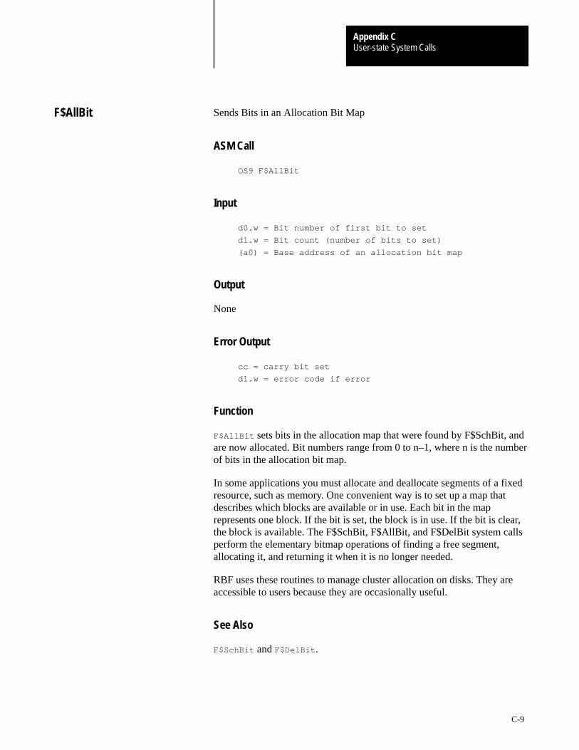
User-state System CallsAppendix C
C-9
Sends Bits in an Allocation Bit Map
ASM Call
OS9 F$AllBit
Input
d0.w = Bit number of first bit to set
d1.w = Bit count (number of bits to set)
(a0) = Base address of an allocation bit map
Output
None
Error Output
cc = carry bit set
d1.w = error code if error
Function
F$AllBit sets bits in the allocation map that were found by F$SchBit, andare now allocated. Bit numbers range from 0 to n–1, where n is the numberof bits in the allocation bit map.
In some applications you must allocate and deallocate segments of a fixedresource, such as memory. One convenient way is to set up a map thatdescribes which blocks are available or in use. Each bit in the maprepresents one block. If the bit is set, the block is in use. If the bit is clear,the block is available. The F$SchBit, F$AllBit, and F$DelBit system callsperform the elementary bitmap operations of finding a free segment,allocating it, and returning it when it is no longer needed.
RBF uses these routines to manage cluster allocation on disks. They areaccessible to users because they are occasionally useful.
See Also
F$SchBit and F$DelBit .
F$AllBit
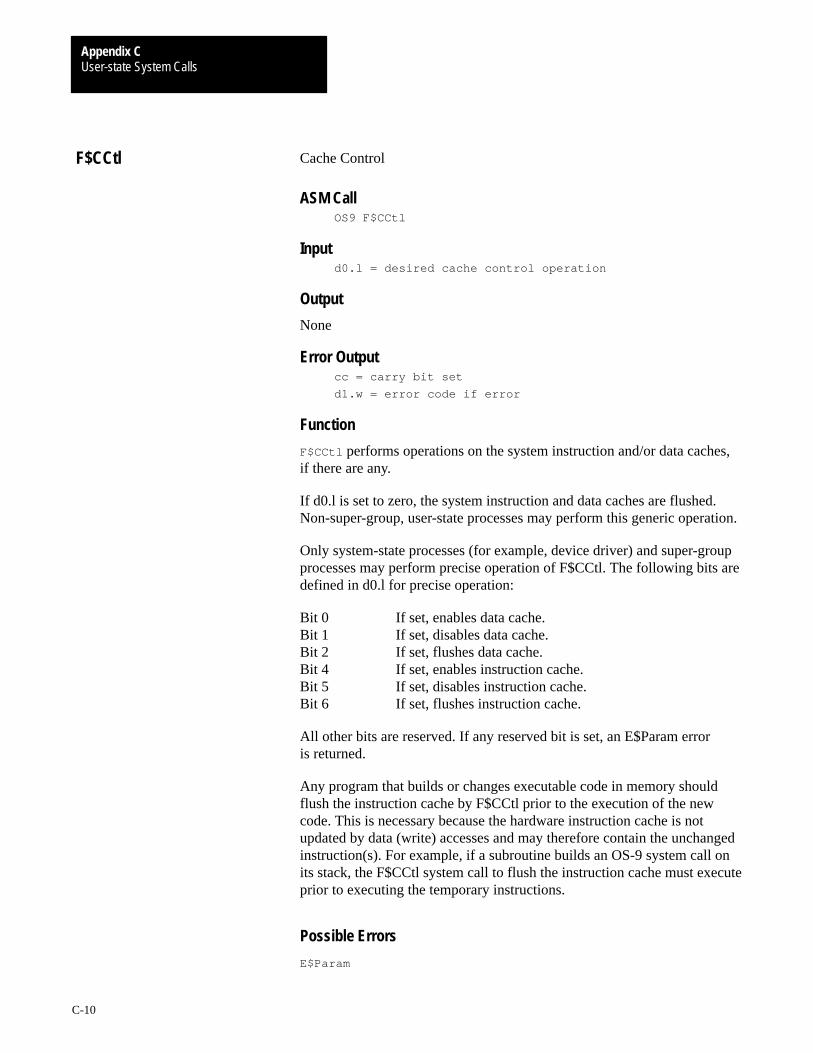
User-state System CallsAppendix C
C-10
Cache Control
ASM CallOS9 F$CCtl
Inputd0.l = desired cache control operation
Output
None
Error Outputcc = carry bit set
d1.w = error code if error
Function
F$CCtl performs operations on the system instruction and/or data caches,if there are any.
If d0.l is set to zero, the system instruction and data caches are flushed.Non-super-group, user-state processes may perform this generic operation.
Only system-state processes (for example, device driver) and super-groupprocesses may perform precise operation of F$CCtl. The following bits aredefined in d0.l for precise operation:
Bit 0 If set, enables data cache.Bit 1 If set, disables data cache.Bit 2 If set, flushes data cache.Bit 4 If set, enables instruction cache.Bit 5 If set, disables instruction cache.Bit 6 If set, flushes instruction cache.
All other bits are reserved. If any reserved bit is set, an E$Param erroris returned.
Any program that builds or changes executable code in memory shouldflush the instruction cache by F$CCtl prior to the execution of the newcode. This is necessary because the hardware instruction cache is notupdated by data (write) accesses and may therefore contain the unchangedinstruction(s). For example, if a subroutine builds an OS-9 system call onits stack, the F$CCtl system call to flush the instruction cache must executeprior to executing the temporary instructions.
Possible Errors
E$Param
F$CCtl
User-state System CallsAppendix C
C-11
Load and Execute New Primary Module
ASM Call
OS9 F$Chain
Input
d0.w = desired module type/language (must be
program/object or 0=any)
d1.l = additional memory size
d2.l = parameter size
d3.w = number of I/O paths to copy
d4.w = priority
(a0) = module name ptr
(a1) = parameter ptr
Output
None: F$Chain does not return to the calling process.
Error Output
cc = carry bit set
d1.w = error code if error
Function
F$Chain executes an entirely new program, but without the overhead ofcreating a new process. It is similar to a Fork command followed by anEXIT. F$Chain effectively resets the calling process’s program and datamemory areas and begins execution of a new primary module. Open pathsare not closed or otherwise affected.
Chain executes as follows:
1. The process’s old primary module is unlinked.
2. The system parses the name string of the new process’s primarymodule (the program that will be executed). Next, the system moduledirectory is searched to see if a module of the same name andtype/language is already in memory. If so, the module is linked. Ifnot, the name string is used as the pathlist of a file which is to beloaded into memory. The first module in this file is linked.
3. The data memory area is reconfigured to the specified size in the newprimary module’s header.
4. Intercepts and any pending signals are erased.
F$Chain
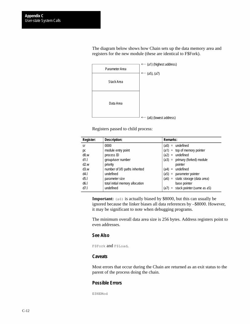
User-state System CallsAppendix C
C-12
The diagram below shows how Chain sets up the data memory area andregisters for the new module (these are identical to F$Fork).
Data Area
(a1) (highest address)
(a5), (a7)
(a6) (lowest address)
Parameter Area
Stack Area
Registers passed to child process:
Register: Description: Remarks:
sr 0000 (a0) = undefinedpc module entry point (a1) = top of memory pointerd0.w process ID (a2) = undefinedd1.l group/user number (a3) = primary (forked) moduled2.w priority pointerd3.w number of I/O paths inherited (a4) = undefinedd4.l undefined (a5) = parameter pointerd5.l parameter size (a6) = static storage (data area)d6.l total initial memory allocation base pointerd7.l undefined (a7) = stack pointer (same as a5)
Important: (a6) is actually biased by $8000, but this can usually beignored because the linker biases all data references by –$8000. However,it may be significant to note when debugging programs.
The minimum overall data area size is 256 bytes. Address registers point toeven addresses.
See Also
F$Fork and F$Load .
Caveats
Most errors that occur during the Chain are returned as an exit status to theparent of the process doing the chain.
Possible Errors
E$NEMod

User-state System CallsAppendix C
C-13
Compare Two Names
ASM Call
OS9 F$CmpNam
Input
d1.w = Length of pattern string
(a0) = Pointer to pattern string
(a1) = Pointer to target string
Output
cc = Carry bit clear if the strings match
Error Output
cc = carry bit set
d1.w = error code if error
Function
F$CmpNam compares a target name to a source pattern to determine if theyare equal. Upper and lower case are considered to match. Two wild cardcharacters are recognized in the pattern string:
question mark (?) matches any single character asterisk (*) matches any string
The target name must be terminated by a null byte.
Possible Errors
E$Differ The names do not match.E$StkOvf The pattern is too complex.
F$CmpNam

User-state System CallsAppendix C
C-14
Copy External Memory
ASM Call
OS9 F$CpyMem
Input
d0.w = process ID of external memory’s owner
d1.l = number of bytes to copy
(a0) = address of memory in external process to copy
(a1) = caller’s destination buffer pointer
Output
None
Error Output
cc = carry bit set
d1.w = error code if error
Function
F$CpyMem copies external memory into your buffer for inspection. You canuse F$CpyMem to copy portions of the system’s address space. This isespecially helpful in examining modules. You can view any memory in thesystem with F$CpyMem.
See Also
F$Move
F$CpyMem
User-state System CallsAppendix C
C-15
Generate CRC
ASM CallOS9 F$CRC
Inputd0.l = Data byte count
d1.l = CRC accumulator
(a0) = Pointer to data
Outputd1.l = Updated CRC accumulator
Error Outputcc = carry bit set
d1.w = error code if error
Function
F$CRC generates or checks the CRC (cyclic redundancy check) values ofsections of memory. Compilers, assemblers, or other module generatorsuse F$CRC to generate a valid module CRC.
If the CRC of a new module is to be generated, the CRC is accumulatedover the entire module, excluding the CRC itself. The accumulated CRC iscomplemented and then stored in the correct position in the module.
You can calculate the CRC starting at the source address over a specifiednumber of bytes. It is not necessary to cover an entire module in one call,since the CRC may be accumulated over several calls. The CRCaccumulator must be initialized to $FFFFFFFF before the first F$CRC callfor any particular module.
An easier method of checking an existing module’s CRC is to perform thecalculation on the entire module, including the module CRC. The CRCaccumulator contains the CRC constant bytes if the module CRC is correct.The CRC constant is defined in sys.l and usr.l as CRCCon. Its valueis $00800FE3.
See AlsoOS-9 Technical Overview, Chapter 1, section on CRC.
CaveatsThe CRC value is three bytes long, in a four-byte field. To generate a validmodule CRC, the caller must include the byte preceding the CRC in thecheck. This byte must be initialized to zero. For convenience, if a datapointer of zero is passed, the CRC is updated with one zero data byte.F$CRC always returns $FF in the most significant byte of d1, so d1.l may bedirectly stored (after complement) in the last four bytes of a module as thecorrect CRC.
F$CRC
User-state System CallsAppendix C
C-16
Create Data Module
ASM Call
OS9 F$DatMod
Input
d0.l = size of data required (not including header or
CRC)
d1.w = desired attr/revision
d2.w = desired access permission
d3.w = desired type/language (optional)
d4.l = memory color type (optional)
(a0) = module name string ptr
Output
d0.w = module type/language
d1.w = module attr/revision
(a0) = updated name string ptr
(a1) = module data ptr (’execution’ entry)
(a2) = module header ptr
Error Output
cc = carry bit set
d1.w = error code if error
Function
F$DatMod creates a data module with the specified attribute/revision andclears the data portion of the module. The module is initially created with avalid CRC, and entered into the system module directory. Severalprocesses can communicate with each other using a shared data module.
Be careful not to modify the data module’s header or name string to avoidthe possibility of the module becoming unknown to the system.
F$DatMod
User-state System CallsAppendix C
C-17
Caveats
The module created contains at least d0.l usable data bytes, but may besomewhat larger. The module itself will be larger by at least the size of themodule header and CRC, and rounded up to the nearest system memoryallocation boundary.
See Also
F$SetCRC and F$Move.
Possible Errors
E$Differ The names do not match.E$StkOvf The pattern is too complex.
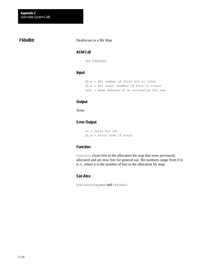
User-state System CallsAppendix C
C-18
Deallocate in a Bit Map
ASM Call
OS9 F$DelBit
Input
d0.w = Bit number of first bit to clear
d1.w = Bit count (number of bits to clear)
(a0) = Base address of an allocation bit map
Output
None
Error Output
cc = carry bit set
d1.w = error code if error
Function
F$DelBit clears bits in the allocation bit map that were previouslyallocated and are now free for general use. Bit numbers range from 0 ton–1, where n is the number of bits in the allocation bit map.
See Also
F$AllBitF$CpyMem and F$SchBit .
F$DelBit

User-state System CallsAppendix C
C-19
Execute Debugged Program
ASM Call
OS9 F$DExec
Input
d0.w = process ID of child to execute
d1.l = number of instructions to execute (0 =
continuous)
d2.w = number of breakpoints in list
(a0) = breakpoint list
register buffer contains child register image
Output
d0.l = total number of instructions executed so far
d1.l = remaining count not executed
d2.w = exception occurred, if non–zero; exception offset
d3.w = classification word (addr or bus trap only)
d4.l = access address (addr or bus trap only)
d5.w = instruction register (addr or bus trap only)
register buffer updated
Error Output
cc = carry bit set
d1.w = error code if error
Function
F$DExec controls the execution of a suspended child process that has beencreated by the F$DFork call. The process performing F$DExec issuspended and its debugged child process is executed instead. Once thespecified number of instructions are executed, a breakpoint is reached or anunexpected exception occurs, execution terminates, and control returns tothe parent process. Thus, the parent and the child processes are neveractive at the same time.
F$DExec traces every instruction of the child process. It checks for thetermination conditions after each instruction. Breakpoints are simply listsof addresses to check and work with ROMed object programs.Consequently, the child process being debugged runs at a slow speed.
F$DExec

User-state System CallsAppendix C
C-20
If a –1 (hex $FFFFFFFF) is passed in d1.l, F$DExec replaces theinstruction at each breakpoint address with an illegal opcode. It thenexecutes the child process at full speed (with the trace bit clear) until abreakpoint is reached or the program terminates. This can save anenormous amount of time, but it is impossible for F$DExec to count thenumber of executed instructions.
Any OS-9 system calls made by the suspended program are executed atfull speed and are considered one logical instruction. The same is true ofsystem-state trap handlers. You cannot debug system-state processes.
The system uses the register buffer passed in the F$DFork call to save andrestore the child’s registers. Changing the contents of the register bufferalters the child process’s registers.
If the child process terminates for any reason, the carry bit is set andreturned. Tracing may continue as long as the child process does notperform a F$Exit (even after encountering any normally fatal error). AF$DExit call must be made to return the debugged process’sresources (memory).
See Also
F$DFork and F$DExit .
Caveats
Tracing is allowed through user-state trap handlers, intercept routines, andthe F$Chain system call. This is not a problem, but may seem strangeat times.
Possible Errors
E$IPrcID and E$PrcAbt .

User-state System CallsAppendix C
C-21
Exit Debugged Program
ASM Call
OS9 F$DExit
Input
d0.w = process ID of child to terminate
Output
cc = carry bit set
d1.w = error code if error
Error Output
None
Function
F$DExit terminates a suspended child process that was created with theF$DFork system call. To permit post-mortem examination, normaltermination by the child process does not release any of its resources.
See Also
F$Exit , F$DFork , and F$DExec.
Possible Errors
E$IPrcID
F$DExit
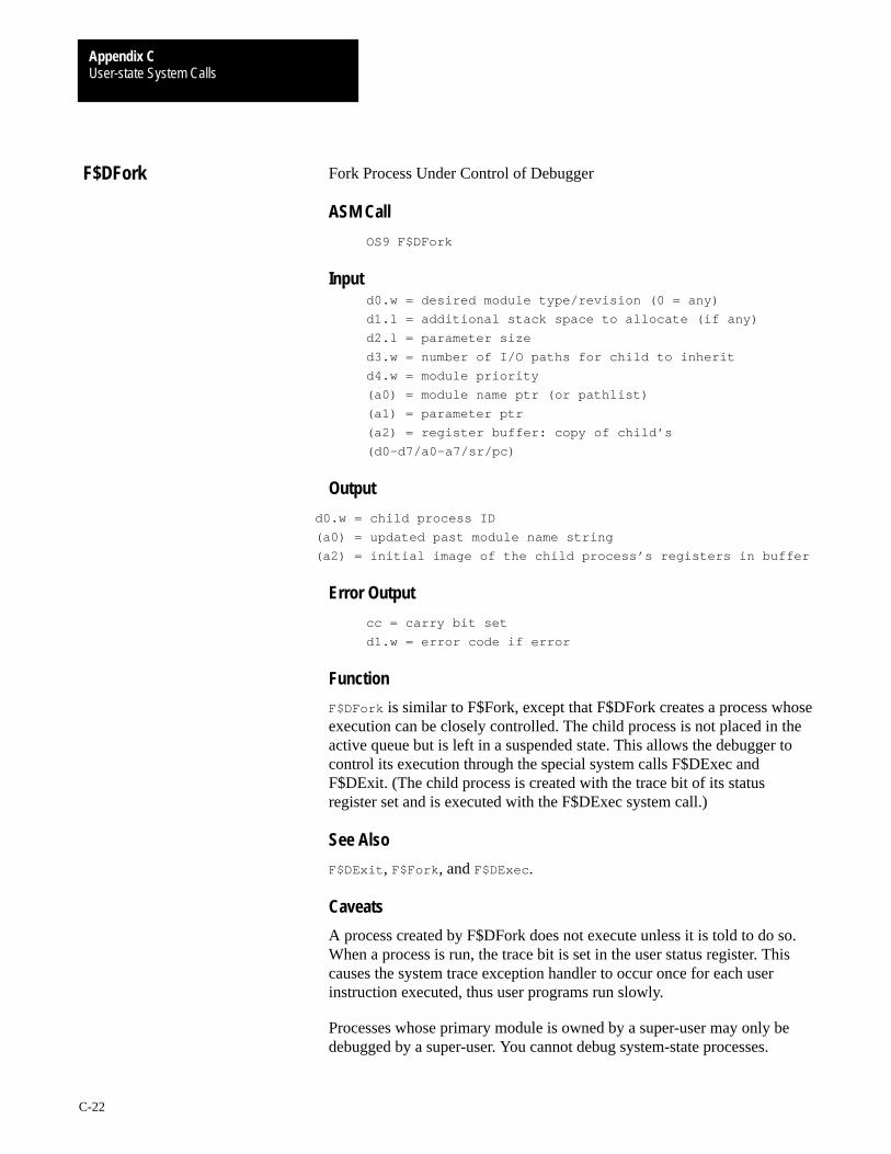
User-state System CallsAppendix C
C-22
Fork Process Under Control of Debugger
ASM Call
OS9 F$DFork
Inputd0.w = desired module type/revision (0 = any)
d1.l = additional stack space to allocate (if any)
d2.l = parameter size
d3.w = number of I/O paths for child to inherit
d4.w = module priority
(a0) = module name ptr (or pathlist)
(a1) = parameter ptr
(a2) = register buffer: copy of child’s
(d0–d7/a0–a7/sr/pc)
Output
d0.w = child process ID
(a0) = updated past module name string
(a2) = initial image of the child process’s registers in buffer
Error Output
cc = carry bit set
d1.w = error code if error
Function
F$DFork is similar to F$Fork, except that F$DFork creates a process whoseexecution can be closely controlled. The child process is not placed in theactive queue but is left in a suspended state. This allows the debugger tocontrol its execution through the special system calls F$DExec andF$DExit. (The child process is created with the trace bit of its statusregister set and is executed with the F$DExec system call.)
See Also
F$DExit , F$Fork , and F$DExec.
Caveats
A process created by F$DFork does not execute unless it is told to do so.When a process is run, the trace bit is set in the user status register. Thiscauses the system trace exception handler to occur once for each userinstruction executed, thus user programs run slowly.
Processes whose primary module is owned by a super-user may only bedebugged by a super-user. You cannot debug system-state processes.
F$DFork

User-state System CallsAppendix C
C-23
Create, Manipulate, and Delete Events
ASM Call
OS9 F$Event
Input
d1.w = Event function code
All others are dependent on function code
Output
Dependent on function code
Error Output
Dependent on function code
Function
Events are multiple-value semaphores that synchronize concurrentprocesses which share resources such as files, data modules, and CPUtime. F$Event provides facilities to create and delete events, to permitprocesses to link/unlink events and obtain event information, to suspendoperation until an event occurs, and for various means of signaling.
An OS-9 event is a 32-byte system global variable maintained by thesystem. The following fields are included in each event:
Field: Description:
Event ID This number and the event’s array position are used to create a unique ID.
Event name This name must be unique and cannot exceed 12 characters.
Event value This four-byte integer value has a range of two billion.
Wait increment This value is added to the event value when a process waits for the event.It is set when the event is created and does not change.
Signal increment This value is added to the event value when the event is signaled. Thisvalue is set when the event is created and does not change.
Link Count This is the event use count.
Next event This is a pointer to the next process in the event queue. An event queue iscircular and includes all processes waiting for the event. Each time theevent is signaled, this queue is searched.
Previous event This is a pointer to the previous process in the event queue.
F$Event

User-state System CallsAppendix C
C-24
The following function codes are supported:
Ev$Link Link to existing event by nameEv$UnLnk Unlink eventEv$Creat Create new eventEv$Delet Delete existing eventEv$Wait Wait for event to occurEv$WaitR Wait for relative to occurEv$Read Read event value without waitingEv$Info Return event informationEv$Pulse Signal an event occurrenceEv$Signl Signal an event occurrenceEv$Set Set event variable and signal an event occurrenceEv$SetR Set relative event variable; signal an event occurrence
Possible Errors
Dependent on function code
See Also
OS-9 Technical Overview Chapter 4, the section on Events.

User-state System CallsAppendix C
C-25
Link to Existing Event by Name
Input
(a0) = event name string pointer (max 11 chars)
d1.w = 0 (Ev$Link function code)
Output
d0.l = event ID number
(a0) = updated past event name
Error Output
cc = carry bit set
d1.w = error code if error
Function
Ev$Link determines the ID number of an existing event. Once an event islinked, all subsequent references are made using the event ID returned.This permits the system to access events quickly, while protecting againstprograms using invalid or deleted events. The event use count isincremented when an Ev$Link is performed. To keep the use countsynchronized properly, perform an Ev$UnLnk when the event will nolonger be used.
Possible Errors
E$BNam Name is syntactically incorrect or longer than 11 chars.E$EvNF Event not found in the event table.
Ev$Link

User-state System CallsAppendix C
C-26
Unlink Event
Input
d0.l = event ID number
d1.w = 1 (Ev$UnLnk function code)
Output
None
Error Output
cc = carry bit set
d1.w = error code if error
Function
Ev$Unlnk informs the system that a process will no longer use an event.The event use count is decremented and the event is deleted when thecount reaches zero. OS-9 uses this only for error checking.
Possible Errors
E$EvntID ID specified is not a valid active event.
Ev$UnLnk
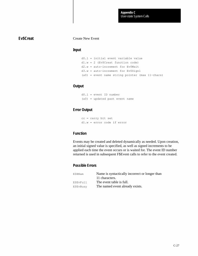
User-state System CallsAppendix C
C-27
Create New Event
Input
d0.l = initial event variable value
d1.w = 2 (Ev$Creat function code)
d2.w = auto–increment for Ev$Wait
d3.w = auto–increment for Ev$Signl
(a0) = event name string pointer (max 11–chars)
Output
d0.l = event ID number
(a0) = updated past event name
Error Output
cc = carry bit set
d1.w = error code if error
Function
Events may be created and deleted dynamically as needed. Upon creation,an initial signed value is specified, as well as signed increments to beapplied each time the event occurs or is waited for. The event ID numberreturned is used in subsequent F$Event calls to refer to the event created.
Possible Errors
E$BNam Name is syntactically incorrect or longer than11 characters.
E$EvFull The event table is full.E$EvBusy The named event already exists.
Ev$Creat
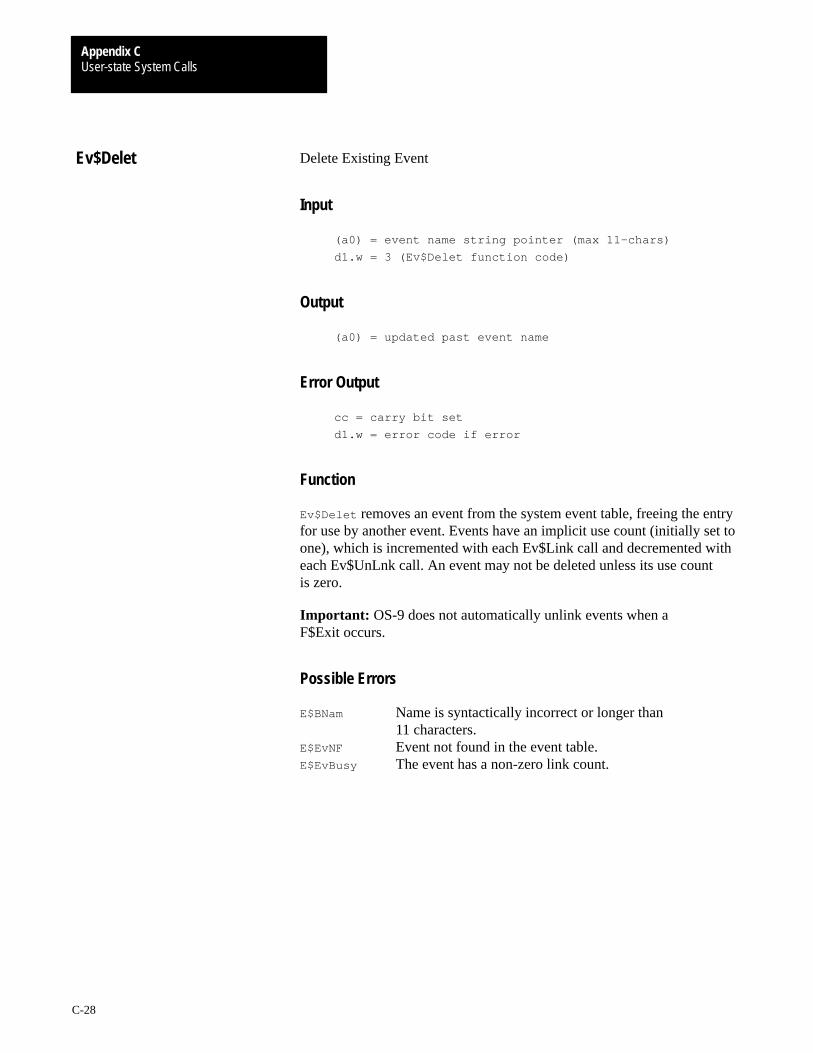
User-state System CallsAppendix C
C-28
Delete Existing Event
Input
(a0) = event name string pointer (max 11–chars)
d1.w = 3 (Ev$Delet function code)
Output
(a0) = updated past event name
Error Output
cc = carry bit set
d1.w = error code if error
Function
Ev$Delet removes an event from the system event table, freeing the entryfor use by another event. Events have an implicit use count (initially set toone), which is incremented with each Ev$Link call and decremented witheach Ev$UnLnk call. An event may not be deleted unless its use countis zero.
Important: OS-9 does not automatically unlink events when aF$Exit occurs.
Possible Errors
E$BNam Name is syntactically incorrect or longer than11 characters.
E$EvNF Event not found in the event table.E$EvBusy The event has a non-zero link count.
Ev$Delet
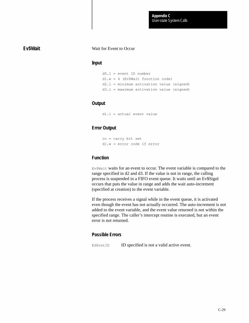
User-state System CallsAppendix C
C-29
Wait for Event to Occur
Input
d0.l = event ID number
d1.w = 4 (Ev$Wait function code)
d2.l = minimum activation value (signed)
d3.l = maximum activation value (signed)
Output
d1.l = actual event value
Error Output
cc = carry bit set
d1.w = error code if error
Function
Ev$Wait waits for an event to occur. The event variable is compared to therange specified in d2 and d3. If the value is not in range, the callingprocess is suspended in a FIFO event queue. It waits until an Ev$Signloccurs that puts the value in range and adds the wait auto-increment(specified at creation) to the event variable.
If the process receives a signal while in the event queue, it is activatedeven though the event has not actually occurred. The auto-increment is notadded to the event variable, and the event value returned is not within thespecified range. The caller’s intercept routine is executed, but an eventerror is not returned.
Possible Errors
E$EvntID ID specified is not a valid active event.
Ev$Wait
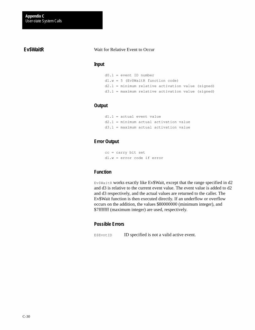
User-state System CallsAppendix C
C-30
Wait for Relative Event to Occur
Input
d0.l = event ID number
d1.w = 5 (Ev$WaitR function code)
d2.l = minimum relative activation value (signed)
d3.l = maximum relative activation value (signed)
Output
d1.l = actual event value
d2.l = minimum actual activation value
d3.l = maximum actual activation value
Error Output
cc = carry bit set
d1.w = error code if error
Function
Ev$WaitR works exactly like Ev$Wait, except that the range specified in d2and d3 is relative to the current event value. The event value is added to d2and d3 respectively, and the actual values are returned to the caller. TheEv$Wait function is then executed directly. If an underflow or overflowoccurs on the addition, the values $80000000 (minimum integer), and$7fffffff (maximum integer) are used, respectively.
Possible Errors
E$EvntID ID specified is not a valid active event.
Ev$WaitR
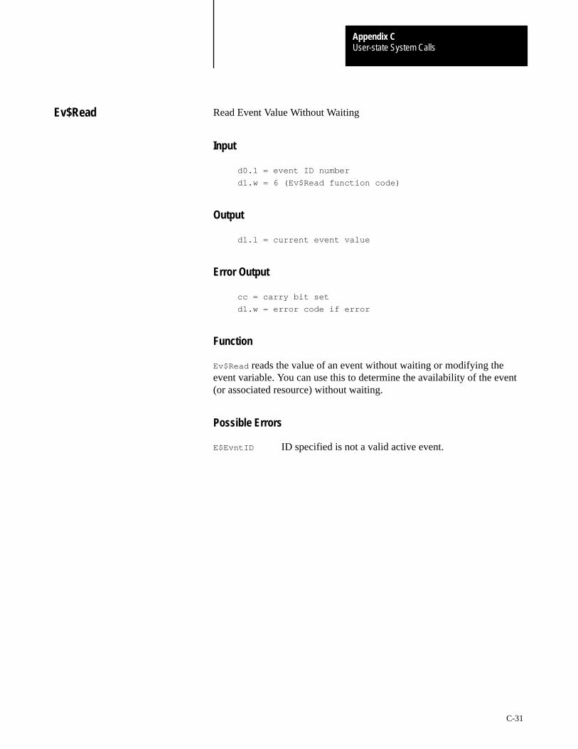
User-state System CallsAppendix C
C-31
Read Event Value Without Waiting
Input
d0.l = event ID number
d1.w = 6 (Ev$Read function code)
Output
d1.l = current event value
Error Output
cc = carry bit set
d1.w = error code if error
Function
Ev$Read reads the value of an event without waiting or modifying theevent variable. You can use this to determine the availability of the event(or associated resource) without waiting.
Possible Errors
E$EvntID ID specified is not a valid active event.
Ev$Read

User-state System CallsAppendix C
C-32
Return Event Information
Input
d0.l = event index (ID number) to begin search
d1.w = 7 (Ev$Info function code)
(a0) = ptr to buffer for event information
Output
d0.l = event index found
(a0) = data returned in buffer
Error Output
cc = carry bit set
d1.w = error code if error
Function
Ev$Info returns a copy of the 32-byte event table entry associated with anevent. Unlike other F$Event functions, Ev$Info only uses the low word ofd0. This index is the system event number, ranging from zero to themaximum number of system events minus one. The event informationblock for the first active event with an index greater than or equal to thisindex is returned in the caller’s buffer. If none exists, an error is returned.Ev$Info is provided for utilities needing to determine the status of allactive events.
Possible Errors
E$EvntID The index is above all active events.
Ev$Info

User-state System CallsAppendix C
C-33
Signal an Event Occurrence
Input
d0.l = event ID number
d1.w = MS bit set to activate all processes in range
LS bits = 9 (Ev$Pulse function code)
d2.l = event pulse value
Output
None
Error Output
cc = carry bit set
d1.w = error code if error
Function
Ev$Pulse signals an event occurrence, but differs from Ev$Signl. Theevent variable is set to the value passed in d2, and the signalauto-increment is not applied. Then, the Ev$Signl search routine isexecuted and the original event value is restored.
Possible Errors
E$EvntID The ID specified is not a valid active event.
Ev$Pulse
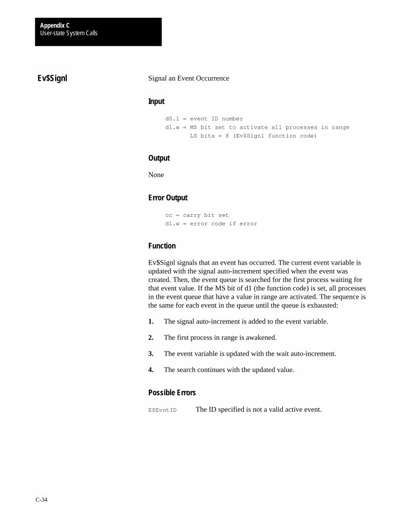
User-state System CallsAppendix C
C-34
Signal an Event Occurrence
Input
d0.l = event ID number
d1.w = MS bit set to activate all processes in range
LS bits = 8 (Ev$Signl function code)
Output
None
Error Output
cc = carry bit set
d1.w = error code if error
Function
Ev$Signl signals that an event has occurred. The current event variable isupdated with the signal auto-increment specified when the event wascreated. Then, the event queue is searched for the first process waiting forthat event value. If the MS bit of d1 (the function code) is set, all processesin the event queue that have a value in range are activated. The sequence isthe same for each event in the queue until the queue is exhausted:
1. The signal auto-increment is added to the event variable.
2. The first process in range is awakened.
3. The event variable is updated with the wait auto-increment.
4. The search continues with the updated value.
Possible Errors
E$EvntID The ID specified is not a valid active event.
Ev$Signl
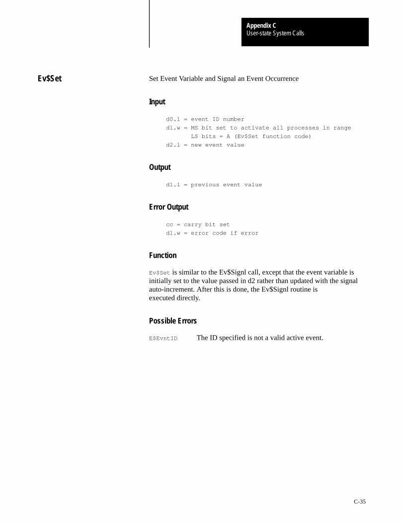
User-state System CallsAppendix C
C-35
Set Event Variable and Signal an Event Occurrence
Input
d0.l = event ID number
d1.w = MS bit set to activate all processes in range
LS bits = A (Ev$Set function code)
d2.l = new event value
Output
d1.l = previous event value
Error Output
cc = carry bit set
d1.w = error code if error
Function
Ev$Set is similar to the Ev$Signl call, except that the event variable isinitially set to the value passed in d2 rather than updated with the signalauto-increment. After this is done, the Ev$Signl routine isexecuted directly.
Possible Errors
E$EvntID The ID specified is not a valid active event.
Ev$Set
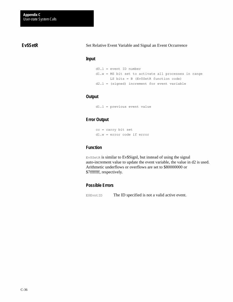
User-state System CallsAppendix C
C-36
Set Relative Event Variable and Signal an Event Occurrence
Input
d0.l = event ID number
d1.w = MS bit set to activate all processes in range
LS bits = B (Ev$SetR function code)
d2.l = (signed) increment for event variable
Output
d1.l = previous event value
Error Output
cc = carry bit set
d1.w = error code if error
Function
Ev$SetR is similar to Ev$Signl, but instead of using the signalauto-increment value to update the event variable, the value in d2 is used.Arithmetic underflows or overflows are set to $80000000 or$7fffffff, respectively.
Possible Errors
E$EvntID The ID specified is not a valid active event.
Ev$SetR

User-state System CallsAppendix C
C-37
Terminate the Calling Process
ASM Call
OS9 F$Exit
Input
d1.w = Status code to be returned to parent process
Output
Process is terminated
Error Output
cc = carry bit set
d1.w = error code if error
Function
F$Exit is the means by which a process can terminate itself. Its datamemory area is de-allocated and its primary module is unlinked. All openpaths are automatically closed.
The death of the process can be detected by the parent executing a F$Waitcall. This returns (to the parent) the status word passed by the child in itsExit call. The shell assumes that the status word is an OS-9 error code thatthe terminating process wishes to pass back to its parent process. Thestatus word could also be a user-defined status value.
Processes called directly by the shell should only return an OS-9 error codeor zero if no error occurred.
Important: The parent MUST do a F$Wait before the process descriptoris returned.
A F$Exit call functions as follows:
1. Close all paths.
2. Return memory to system.
3. Unlink primary module and user trap handlers.
F$Exit
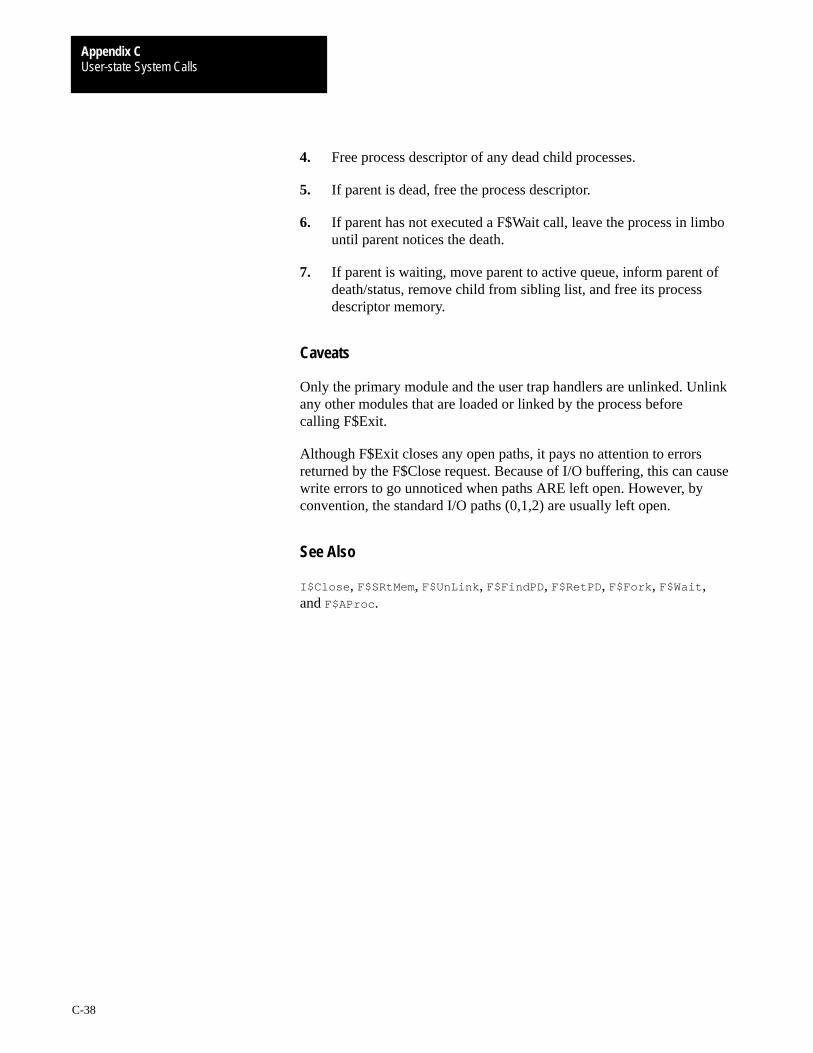
User-state System CallsAppendix C
C-38
4. Free process descriptor of any dead child processes.
5. If parent is dead, free the process descriptor.
6. If parent has not executed a F$Wait call, leave the process in limbountil parent notices the death.
7. If parent is waiting, move parent to active queue, inform parent ofdeath/status, remove child from sibling list, and free its processdescriptor memory.
Caveats
Only the primary module and the user trap handlers are unlinked. Unlinkany other modules that are loaded or linked by the process beforecalling F$Exit.
Although F$Exit closes any open paths, it pays no attention to errorsreturned by the F$Close request. Because of I/O buffering, this can causewrite errors to go unnoticed when paths ARE left open. However, byconvention, the standard I/O paths (0,1,2) are usually left open.
See Also
I$Close , F$SRtMem, F$UnLink , F$FindPD , F$RetPD, F$Fork , F$Wait ,and F$AProc .
User-state System CallsAppendix C
C-39
Create a New Process
ASM Call
OS9 F$Fork
Input
d0.w = desired module type/revision (usually
program/object 0=any)
d1.l = additional memory size
d2.l = parameter size
d3.w = number of I/O paths to copy
d4.w = priority
(a0) = module name pointer
(a1) = parameter pointer
Output
d0.w = child process ID
(a0) = updated beyond module name
Error Output
cc = carry bit set
d1.w = error code if error
Function
F$Fork creates a new process which becomes a child of the caller. It setsup the new process’s memory, MPU registers, and standard I/O paths.
The system parses the name string of the new process’s primary module(the program that will initially be executed). Next, the system moduledirectory is searched to see if the program is already in memory. If so, themodule is linked and executed. If not, the name string is used as thepathlist of the file which is to be loaded into memory. The first module inthis file is linked and executed. To be loaded, the module must be programobject code and have the appropriate read and/or execute permissions setfor the user.
The primary module’s module header is used to determine the process’sinitial data area size. OS-9 then attempts to allocate RAM equal to therequired data storage size plus any additional size specified in d1, plus thesize of any parameter passed. The RAM area must be contiguous.
F$Fork
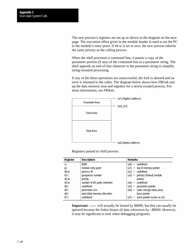
User-state System CallsAppendix C
C-40
The new process’s registers are set up as shown in the diagram on the nextpage. The execution offset given in the module header is used to set the PCto the module’s entry point. If d4.w is set to zero, the new process inheritsthe same priority as the calling process.
When the shell processes a command line, it passes a copy of theparameter portion (if any) of the command line as a parameter string. Theshell appends an end-of-line character to the parameter string to simplifystring-oriented processing.
If any of the these operations are unsuccessful, the fork is aborted and anerror is returned to the caller. The diagram below shows how F$Fork setsup the data memory area and registers for a newly-created process. Formore information, see F$Wait.
Data Area
(a1) (highest address)
(a5), (a7)
(a6) (lowest address)
Parameter Area
Stack Area
Registers passed to child process:
Register: Description: Remarks:
sr 0000 (a0) = undefinedpc module entry point (a1) = top of memory pointerd0.w process ID (a2) = undefinedd1.l group/user number (a3) = primary (forked) moduled2.w priority pointerd3.w number of I/O paths inherited (a4) = undefinedd4.l undefined (a5) = parameter pointerd5.l parameter size (a6) = static storage (data area)d6.l total initial memory allocation base pointerd7.l undefined (a7) = stack pointer (same as a5)
Important: (a6) will actually be biased by $8000, but this can usually beignored because the linker biases all data references by –$8000. However,it may be significant to note when debugging programs.
User-state System CallsAppendix C
C-41
Caveats
Both the child and parent process execute concurrently. If the parentexecutes a F$Wait call immediately after the fork, it waits until the childdies before it resumes execution. A child process descriptor is returnedonly when the parent does a F$Wait call.
Modules owned by a super-user execute in system state if the system-statebit in the module’s attributes is set. This is rarely necessary, quitedangerous, and not recommended for beginners.
See Also
F$Wait , F$Exit , and F$Chain .
Possible Errors
E$IPrcID
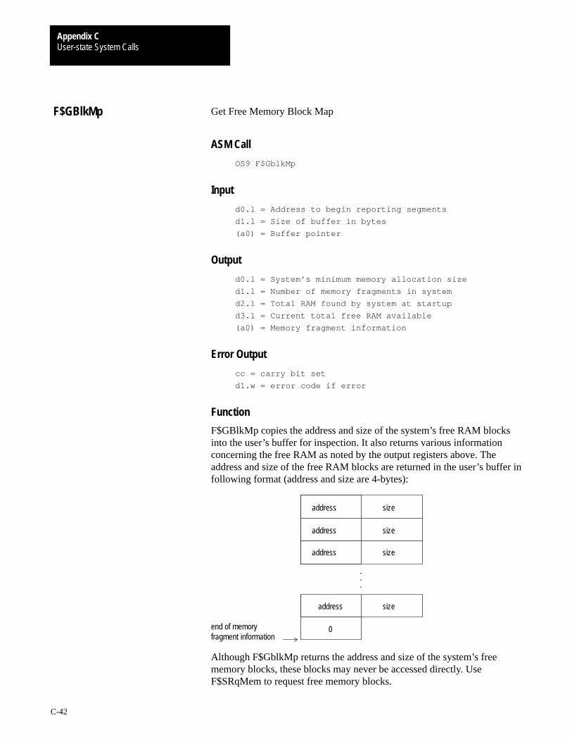
User-state System CallsAppendix C
C-42
Get Free Memory Block Map
ASM Call
OS9 F$GblkMp
Input
d0.l = Address to begin reporting segments
d1.l = Size of buffer in bytes
(a0) = Buffer pointer
Output
d0.l = System’s minimum memory allocation size
d1.l = Number of memory fragments in system
d2.l = Total RAM found by system at startup
d3.l = Current total free RAM available
(a0) = Memory fragment information
Error Output
cc = carry bit set
d1.w = error code if error
Function
F$GBlkMp copies the address and size of the system’s free RAM blocksinto the user’s buffer for inspection. It also returns various informationconcerning the free RAM as noted by the output registers above. Theaddress and size of the free RAM blocks are returned in the user’s buffer infollowing format (address and size are 4-bytes):
end of memoryfragment information
address
address
address
address
size
size
size
size
0
.
.
.
Although F$GblkMp returns the address and size of the system’s freememory blocks, these blocks may never be accessed directly. UseF$SRqMem to request free memory blocks.
F$GBlkMp

User-state System CallsAppendix C
C-43
See Also
F$SRqMem and F$Mem.
Caveats
F$GBlkMp provides a status report concerning free system memory formfree and similar utilities. The address and size of free RAM changes withsystem use. Although F$GblkMp returns the address and size of thesystem’s free memory blocks, these blocks may never be accessed directly.Use F$SRqMem to request free memory blocks.
User-state System CallsAppendix C
C-44
Get Copy of Module Directory
ASM Call
OS9 F$GModDr
Input
d1.l = Maximum number of bytes to copy
(a0) = Buffer pointer
Output
d1.l = Actual number of bytes copied
Error Output
cc = Carry bit set
d1.w = Appropriate error code
Function
F$GModDr copies the system’s module directory into the user’s buffer forinspection. mdir uses F$GModDr to look at the module directory. Althoughthe module directory contains pointers to each module in the system, themodules should never be accessed directly. Rather, use a F$CpyMem callto copy portions of the system’s address space for inspection. On somesystems, directly accessing the modules may cause address or bustrap errors.
See Also
F$Move and F$CpyMem.
Caveats
This system call is provided primarily for use by mdir and similar utilities.The format and contents of the module directory may change on differentreleases of OS-9. For this reason, it is often preferable to use the output ofmdir to determine the names of modules in memory.
F$GModDr

User-state System CallsAppendix C
C-45
Get Copy of Process Descriptor Block Table
ASM Call
OS9 F$GPrDBT
Input
d1.l = maximum number of bytes to copy
(a0) = Buffer pointer
Output
d1.l = Actual number of bytes copied
Error Output
cc = Carry bit set
d1.w = Appropriate error code
Function
F$GPrDBT copies the process descriptor block table into the caller’s bufferfor inspection. The procs utility uses F$GPrDBT to quickly determinewhich processes are active in the system. Although F$GPrDBT returnspointers to the process descriptors of all processes, NEVER access theprocess descriptors directly. Instead, use the F$GPrDsc system call if youneed to inspect particular process descriptors.
The system call, F$AllPd, describes the format of the process descriptorblock table.
See Also
F$GPrDsc and F$AllPd .
F$GPrDBT
User-state System CallsAppendix C
C-46
Get Copy of the Process Descriptor
ASM Call
OS9 F$GPrDsc
Input
d0.w = Requested process ID
d1.w = Number of bytes to copy
(a0) = Process descriptor buffer pointer
Output
None
Error Output
cc = Carry bit set
d1.w = Appropriate error code
Function
F$GPrDsc copies a process descriptor into the caller’s buffer for inspection.There is no way to change data in a process descriptor. The procs utilityuses F$GPrDsc to gain information about an existing process.
See Also
F$GPrDBT
Caveats
The format and contents of a process descriptor may change with differentreleases of OS-9.
Possible Errors
E$PrcID
F$GPrDsc
User-state System CallsAppendix C
C-47
Get Gregorian Date
ASM Call
OS9 F$Gregor
Input
d0.l = time (seconds since midnight)
d1.l = Julian date
Output
d0.l = time (00hhmmss)
d1.l = date (yyyymmdd)
Error Output
cc = Carry bit set
d1.w = Appropriate error code
Function
F$Gregor converts Julian dates to Gregorian dates. Gregorian dates areconsidered the normal calendar dates.
The Julian date is similar to the Julian date used by astronomers. It is basedon the number of days that have elapsed since January 1, 4713 B.C. Eachastronomical Julian day changes at noon. OS-9 differs slightly from theastronomical standard by changing Julian dates at midnight. It is relativelyeasy to adjust for this, when necessary.
Caveats
The normal (Gregorian) calendar was revised to correct errors due to leapyear at different dates throughout the world. The algorithm used by OS-9makes this adjustment on October 15, 1582. Be careful when you areworking with old dates, because the same day may be recorded as adifferent date by different sources.
Important: F$Gregor is the inverse function of F$Julian.
See Also
F$Julian and F$Time .
F$Gregor

User-state System CallsAppendix C
C-48
Get Process ID / User ID
ASM Call
OS9 F$ID
Input
None
Output
d0.w = Current process ID
d1.l = Current process group/user number
d2.w = Current process priority
Error Output
cc = Carry bit set
d1.w = Appropriate error code
Function
F$ID returns the caller’s process ID number, group and user ID, andcurrent process priority (all word values). The process ID is assigned byOS9 and is unique to the process. The user ID is defined in the systempassword file, and is used for system and file security. Several processescan have the same user ID.
F$ID
User-state System CallsAppendix C
C-49
Set Up a Signal Intercept Trap
ASM Call
OS9 F$Icpt
Input(a0) = Address of the intercept routine
(a6) = Address to be passed to the intercept routine
Output
Signals sent to the process will cause the intercept
routine to be called instead of the process being
killed.
Error Output
None
Function
F$Icpt tells OS-9 to install a signal intercept routine: (a0) contains theaddress of the signal handler routine, and (a6) usually contains the addressof the program’s data area.
After the F$Icpt call has been made, whenever the process receives asignal, its intercept routine executes. A signal aborts a process which hasnot used the F$Icpt service request and its termination status (registerd1.w) is the signal code. Many interactive programs set up an interceptroutine to handle keyboard abort and keyboard interrupt signals.
The intercept routine is entered asynchronously because a signal may besent at any time (similar to an interrupt) and is passed the following:
d1.w = Signal code
(a6) = Address of intercept routine data area
The intercept routine should be short and fast, such as setting a flag in theprocess’s data area. Avoid complicated system calls (such as I/O). After theintercept routine is complete, it may return to normal process execution byexecuting the F$RTE system call.
See Also
F$RTE and F$Send.
Caveats
Each time the intercept routine is called, 70 bytes are used on theuser’s stack.
F$Icpt
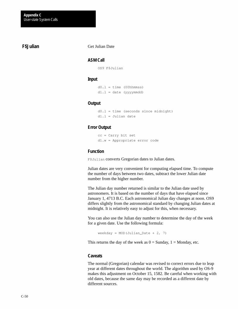
User-state System CallsAppendix C
C-50
Get Julian Date
ASM Call
OS9 F$Julian
Input
d0.l = time (00hhmmss)
d1.l = date (yyyymmdd)
Output
d0.l = time (seconds since midnight)
d1.l = Julian date
Error Output
cc = Carry bit set
d1.w = Appropriate error code
Function
F$Julian converts Gregorian dates to Julian dates.
Julian dates are very convenient for computing elapsed time. To computethe number of days between two dates, subtract the lower Julian datenumber from the higher number.
The Julian day number returned is similar to the Julian date used byastronomers. It is based on the number of days that have elapsed sinceJanuary 1, 4713 B.C. Each astronomical Julian day changes at noon. OS9differs slightly from the astronomical standard by changing Julian dates atmidnight. It is relatively easy to adjust for this, when necessary.
You can also use the Julian day number to determine the day of the weekfor a given date. Use the following formula:
weekday = MOD(Julian_Date + 2, 7)
This returns the day of the week as 0 = Sunday, 1 = Monday, etc.
Caveats
The normal (Gregorian) calendar was revised to correct errors due to leapyear at different dates throughout the world. The algorithm used by OS-9makes this adjustment on October 15, 1582. Be careful when working withold dates, because the same day may be recorded as a different date bydifferent sources.
F$Julian

User-state System CallsAppendix C
C-51
Link to Memory Module
ASM Call
OS9 F$Link
Input
d0.w = Desired module type/language byte (0 = any)
(a0) = Module name string pointer
Output
d0.w = Actual module type/language
d1.w = Module attributes/revision level
(a0) = Updated past the module name
(a1) = Module execution entry point
(a2) = Module pointer
Error Output
cc = Carry bit set
d1.w = Appropriate error code
Function
F$Link causes OS-9 to search the module directory for a module having aname, language, and type as given in the parameters. If found, the addressof the module’s header is returned in (a2). The absolute address of themodule’s execution entry point is returned in (a1). As a convenience, youcan obtain this and other information from the module header. Themodule’s link count is incremented to keep track of how many processesare using the module. If the module requested is not re-entrant, only oneprocess may link to it at a time.
If the module’s access word does not give the process read permission, thelink call fails. Link also fails to find modules whose header has beendestroyed (altered or corrupted) in memory.
See Also
F$Load , F$UnLink , and F$UnLoad .
Possible Errors
E$MNF, E$BNam, and E$ModBsy.
F$Link

User-state System CallsAppendix C
C-52
Load Module(s) From a File
ASM Call
OS9 F$Load
Input
d0.b = Access mode
d1.l = Memory “color” type to load (optional)
(a0) = Pathname string pointer
Output
d0.w = Actual module type/language
d1.w = Attributes/revision level
(a0) = Updated beyond path name
(a1) = Module execution entry pointer (of first module
loaded)
(a2) = Module pointer
Error Output
cc = Carry bit set
d1.w = Appropriate error code
Function
F$Load opens a file specified by the pathlist. It reads one or more memorymodules from the file into memory until it reaches an error or end of file.Then, it closes the file. Modules are usually loaded into the highestphysical memory available.
An error can indicate an actual I/O error, a module with a bad parity orCRC, or that the system memory is full.
All modules that are loaded are added to the system module directory, andthe first module read is linked. The parameters returned are the same asthose returned by a link call, and apply only to the first module loaded.
To be loaded, the file must contain a module or modules that have a propermodule header and CRC. The access mode may be specified as eitherExec_ or Read_, causing the file to load from the current execution or datadirectory, respectively.
F$Load

User-state System CallsAppendix C
C-53
If any of the modules loaded belong to the super-user, the file must also beowned by the super-user. This prevents normal users from executingprivileged service requests.
The input register which specifies memory color type (d1.l) is onlyreferenced if the most significant bit of d0.b is set.
Caveats
F$Load does not work on SCF devices.
Possible Errors
E$MemFul and E$BMID.

User-state System CallsAppendix C
C-54
Resize Data Memory Area
ASM Call
OS9 F$Mem
Input
d0.l = Desired new memory size in bytes
Output
d0.l = Actual size of new memory area in bytes
(a1) = Pointer to new end of data segment (+1)
Error Output
cc = Carry bit set
d1.w = Appropriate error code
Function
F$Mem contracts or expands the process’s data memory area. The new sizerequested is rounded up to an even memory allocation block (16 bytes inversion 2.0). Additional memory is allocated contiguously upward(towards higher addresses), or de-allocated downward from the old highestaddress. If d0 equals zero, the call is considered an information request andthe current upper bound and size is returned.
This request can never return all of a process’s memory, or causedeallocation of memory at its current stack pointer.
The request may return an error upon an expansion request even thoughadequate free memory exists, because the data area must always becontiguous. Memory requests by other processes may fragment memoryinto smaller, scattered blocks that are not adjacent to the caller’s presentdata area.
Possible Errors
E$DelSP, E$MemFul, and E$NoRAM.
F$Mem

User-state System CallsAppendix C
C-55
Print Error Message
ASM Call
OS9 F$PErr
Input
d0.w = Error message path number (0=none)
d1.w = Error number
Output
None
Error Output
None
Function
F$PErr is the system’s error reporting facility. It writes an error message tothe standard error path. Most OS-9 systems will print ERROR #mmm.nnn.Error numbers 000:000 to 063:255 are reserved for the operating system.
If an error path number is specified, the path is searched for a textdescription of the error encountered. The error message path contains anASCII file of error messages. Each line may be up to 80 characters long. Ifthe error number matches the first seven characters in a line (that is,000:215), the rest of the line is printed along with the error number.
Error messages may be continued on several lines by beginning eachcontinuation line with a space. An example error file might contain lineslike this:
000:214 (E$FNA) File not accessible.
An attempt to open a file failed. The file was found, but is inaccessible toyou in the requested mode. Check the file’s owner ID and access attributes.
000:215 (E$BPNam) Bad pathlist specified.
The pathlist specified is syntactically incorrect.
000:216 (E$PNNF) File not found.
F$PErr
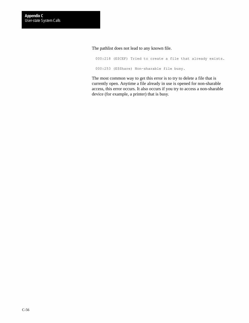
User-state System CallsAppendix C
C-56
The pathlist does not lead to any known file.
000:218 (E$CEF) Tried to create a file that already exists.
000:253 (E$Share) Non–sharable file busy.
The most common way to get this error is to try to delete a file that iscurrently open. Anytime a file already in use is opened for non-sharableaccess, this error occurs. It also occurs if you try to access a non-sharabledevice (for example, a printer) that is busy.
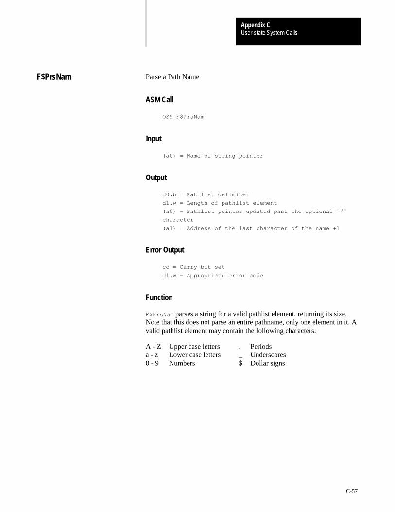
User-state System CallsAppendix C
C-57
Parse a Path Name
ASM Call
OS9 F$PrsNam
Input
(a0) = Name of string pointer
Output
d0.b = Pathlist delimiter
d1.w = Length of pathlist element
(a0) = Pathlist pointer updated past the optional “/”
character
(a1) = Address of the last character of the name +1
Error Output
cc = Carry bit set
d1.w = Appropriate error code
Function
F$PrsNam parses a string for a valid pathlist element, returning its size.Note that this does not parse an entire pathname, only one element in it. Avalid pathlist element may contain the following characters:
A - Z Upper case letters . Periodsa - z Lower case letters _ Underscores0 - 9 Numbers $ Dollar signs
F$PrsNam

User-state System CallsAppendix C
C-58
Any other character terminates the name and is returned as thepathlist delimiter.
Important: F$PrsNam processes only one name, so several calls may beneeded to process a pathlist that has more than one name. F$PrsNam
terminates a name on recognizing a delimiter character. Pathlists areusually terminated with a null byte.
AFTER F$PrsNam CALL:
/
(a0)
00ELIF/0D
BEFORE F$PrsNam CALL:
/
(a0)
(a1) d0.b = ”/”d1.w = 2
00ELIF/0D
See Also
F$CmpNam
Possible Errors
E$BNam
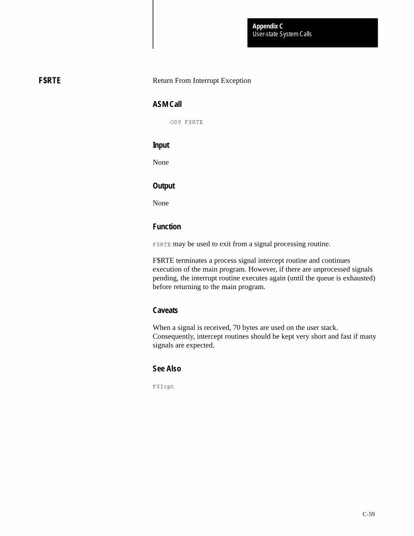
User-state System CallsAppendix C
C-59
Return From Interrupt Exception
ASM Call
OS9 F$RTE
Input
None
Output
None
Function
F$RTE may be used to exit from a signal processing routine.
F$RTE terminates a process signal intercept routine and continuesexecution of the main program. However, if there are unprocessed signalspending, the interrupt routine executes again (until the queue is exhausted)before returning to the main program.
Caveats
When a signal is received, 70 bytes are used on the user stack.Consequently, intercept routines should be kept very short and fast if manysignals are expected.
See Also
F$Icpt
F$RTE

User-state System CallsAppendix C
C-60
Search Bit Map For a Free Area
ASM Call
OS9 F$SchBit
Input
d0.w = Beginning bit number to search
d1.w = Number of bits needed
(a0) = Bit map pointer
(a1) = End of bit map (+1) pointer
Output
d0.w = Beginning bit number found
d1.w = Number of bits found
Error Output
cc = Carry bit set
d1.w = Appropriate error code
Function
F$SchBit searches the specified allocation bit map for a free block (clearedbits) of the required length, starting at the beginning bit number (d0.w).F$SchBit returns the offset of the first block found of the specified length.
If no block of the specified size exists, it returns with the carry set,beginning bit number, and size of the largest block found.
See Also
F$AllBit and F$DelBit .
F$SchBit
User-state System CallsAppendix C
C-61
Send a Signal to Another Process
ASM Call
OS9 F$Send
Input
d0.w = Intended receiver’s process ID number (0 = all)
d1.w = Signal code to send
Output
None
Error Output
cc = Carry bit set
d1.w = Appropriate error code
Function
F$Send sends a signal to a specific process. The signal code is a wordvalue. A process may send the same signal to multiple processes of thesame Group/User ID by passing 0 as the receiver’s process ID number. Forexample, the OS-9 Shell command, kill 0, will unconditionally abort allprocesses with the same group/user ID (except the Shell itself). This is ahandy but dangerous tool to get rid of unwanted background tasks.
If you attempt to send a signal to a process that has an unprocessed,previous signal pending, the signal is placed in a FIFO queue of signals forthe individual process. If the process is in the signal intercept routine whenit receives a signal, the new signal is processed when F$RTE executes.
If the destination process for the signal is sleeping or waiting, it isactivated so that it may process the signal. The signal processing interceptroutine is executed, if it exists (see F$Icpt), otherwise the signal aborts thedestination process, and the signal code becomes the exit status(see F$Wait).
An exception is the wakeup signal. It activates a sleeping process but doesnot cause examination of the signal intercept routine and will not abort aprocess that has not made an F$Icpt call.
Some of the signal codes have meanings defined by convention:
F$Send
User-state System CallsAppendix C
C-62
S$Kill = 0 = System abort (unconditional)
S$Wake = 1 = Wake up process
S$Abort = 2 = Keyboard abort
S$Intrpt = 3 = Keyboard interrupt
S$HangUp = 4 = Modem Hangup
5–31 = Reserved for Microware; deadly to I/O
32–255 = Reserved for Microware
256–65535 = User defined
The S$Kill signal may only be sent to processes with the same group ID asthe sender. Super users may kill any process.
Caveat
The I/O system uses the S$Wake signal extensively. It is not reliable ifused by user-state programs.
Signal values less than 32 (S$Deadly) usually cause the current I/Ooperation to terminate with an error status equal to the signal value.
See Also
F$Wait , F$Icpt , and F$Sleep .
Possible Errors
E$IPrcID and E$USigP.
User-state System CallsAppendix C
C-63
Generate Valid CRC in Module
ASM Call
OS9 F$SetCRC
Input
(a0) = module pointer
Output
None
Error Output
cc = Carry bit set
d1.w = Appropriate error code
Function
F$SetCRC updates the header parity and CRC of a module in memory. Themodule may be an existing module known to the system, or simply animage of a module that will subsequently be written to a file. The modulemust have correct size and sync bytes; other parts of the module arenot checked.
See Also
F$CRC
Caveats
The module image must start on an even address or an addresserror occurs.
OS-9 does not permit any modification to the header of a module known tothe system. Modifying the header makes the module inaccessible toother processes.
Possible Errors
E$BMID
F$SetCRC

User-state System CallsAppendix C
C-64
Set/Examine OS-9 System Global Variables
ASM Call
OS9 F$SetSys
Input
d0.w = offset of system global variable to set/examine
d1.l = size of variable in least significant word (1, 2 or 4 bytes).
The most significant bit, if set, indicates an examination
request. Otherwise, the variable is changed to the value in
register d2.
d2.l = new value (if change request)
Output
d2.l = original value of system global variable
Error Output
cc = Carry set
d1.w = Appropriate error code
Function
F$SetSys changes or examines a system global variable. These variableshave a D_ prefix in the system library sys.l. Consult the DEFS files for adescription of the system global variables.
See Also
F$SPrior and the DEFS Files section in the OS-9 Technical I/O Manual
F$SetSys
User-state System CallsAppendix C
C-65
Caveats
Only a super-user can change system variables. Any system variable maybe examined, but only a few may be altered. The only useful variables thatmay be changed are D_MinPty and D_MaxAge. Consult Chapter 2(section on process scheduling) of the OS-9 Technical Overview for anexplanation of what these variables control.
The system global variables are OS-9’s data area. It is highly likely thatthey will change from one release to another. You will probably have torelink programs using this system call to run them on future versionsof OS9.
ATTENTION: The super-user must be extremely careful whenchanging system global variables.

User-state System CallsAppendix C
C-66
Masks/Unmasks Signals During Critical Code
ASM Call
OS9 F$SigMask
Input
d0.l = reserved, must be zero
d1.l = process signal level
0 = clear
1 = set/increment
–1 = decrement
Output
None
Error Output
cc = carry bit set
d1.w = error code if error
Function
F$SigMask enables or disables signals from reaching the calling process. Ifa signal is sent to a process whose mask is disabled, the signal is queueduntil the process mask becomes enabled. The process’s signal interceptroutine is executed with signals inherently masked.
Two exceptions to this rule are the S$Kill and S$Wake signals. S$Kill
terminates the receiving process, regardless of the state of its mask. S$Wake
ensures that the process is active, but does not queue.
When a process makes a F$Sleep or F$Wait system call, its signal mask isautomatically cleared. If a signal is already queued, these calls returnimmediately (to the intercept routine).
Important: Signals are analogous to hardware interrupts. They should bemasked sparingly, and intercept routines should be as short and fastas possible.
F$Sigmask

User-state System CallsAppendix C
C-67
Put Calling Process to Sleep
ASM Call
OS9 F$Sleep
Input
d0.l = Ticks/seconds (length of time to sleep)
Output
d0.l = Remaining number of ticks if awakened prematurely
Error Output
cc = Carry bit set
d1.w = Appropriate error code
Function
F$Sleep deactivates the calling process until the number of ticks requestedhave elapsed. Sleep(0) sleeps indefinitely. Sleep(1) gives up a time slicebut does not necessarily sleep for one tick. You cannot use F$Sleep to timemore accurately than + or – 1 tick, because it is not known when theF$Sleep request was made during the current tick.
A sleep of one tick is effectively a “give up current time slice” request; theprocess is immediately inserted into the active process queue and resumesexecution when it reaches the front of the queue.
A sleep of two or more (n) ticks causes the process to be inserted into theactive process queue after (n – 1) ticks occur and resumes execution whenit reaches the front of the queue. The process is activated before the fulltime interval if a signal (in particular S$Wake) is received. Sleepingindefinitely is a good way to wait for a signal or interrupt without wastingCPU time.
The duration of a tick is system dependent, but is usually .01 seconds. Ifthe high order bit of d0.l is set, the low 31 bits are converted from 256thsof a second into ticks before sleeping to allow program delays to beindependent of the system’s clock rate.
F$Sleep
User-state System CallsAppendix C
C-68
See Also
F$Send and F$Wait .
Caveats
The system clock must be running to perform a timed sleep. The systemclock is not required to perform an indefinite sleep or to give up atime-slice.
Possible Errors
E$NoClk
User-state System CallsAppendix C
C-69
Set Process Priority
ASM Call
OS9 F$SPrior
Input
d0.w = Process ID number
d1.w = Desired process priority: 65535 = highest
0 = lowest
Output
None
Error Output
cc = Carry bit set
d1.w = Appropriate error code
Function
F$SPrior changes the process priority to the new value specified. Aprocess can only change another process’s priority if it has the same userID. The one exception to this rule is a super user (group ID zero), whichmay alter any process’s priority.
There are two system global variables that affect task-switching. D_MinPty
is the minimum priority that a task must have for OS-9 to age or execute it.D_MaxAge is the cutoff aging point. D_MinPty and D_MaxAge are initiallyset in the Init module.
See Also
F$SetSys and the section on process scheduling in Chapter 2 of the OS-9Technical Overview.
Caveats
A very small change in relative priorities has a large effect. For example, iftwo processes have priorities 100 and 200, the process with the higherpriority runs 100 times before the low priority process runs at all. In actualpractice, the difference may not be this extreme because programs spend alot of time waiting for I/O devices.
Possible Errors
E$IPrcID
F$SPrior

User-state System CallsAppendix C
C-70
System Request for Colored Memory
ASM Call
OS9 F$SRqCMem
Input
d0.l = Byte count of requested memory
d1.l = Memory type code (0 = any)
Output
d0.l = Byte count of memory granted
(a2) = Pointer to memory block allocated
Error Output
cc = Carry bit set
d1.w = Appropriate error code
Function
F$SRqCMem allocates a block of a specific type of memory. If a non-zerotype is requested, the search is restricted to memory areas of that type. Thearea with the highest priority is searched first.
When the type code is zero, the search is based only on priority. Thisallows you to configure a system so that fast on-board memory is allocatedbefore slow off-board memory. Areas with a priority of zero are excludedfrom the search.
If more than one memory area has the same priority, the area with thelargest total free space is searched first. This allows memory areas to bebalanced (that is, contain approximately equal amounts of free space).
Memory types or “color codes” are system dependent and may bearbitrarily assigned by the system administrator. Values below 256 arereserved for Microware use.
The number of bytes requested are rounded up to a system definedblocksize, which is currently 16 bytes. The memory always begins on aneven boundary.
F$SRqCMem

User-state System CallsAppendix C
C-71
If –1 is passed in d0.l, the largest block of free memory of the specifiedtype is allocated to the calling process.
F$SRqMem is equivalent to a F$SRqCMem request with a color of zero.
See Also
F$SRqMem, F$SRtMem, and F$Mem; Init module memory definitions andColored Memory discussion in Chapter 2 of the OS-9 Technical Overview.
Possible Errors
E$MemFul, E$NoRAM, and E$Damage.
User-state System CallsAppendix C
C-72
System Memory Request
ASM Call
OS9 F$SRqMem
Input
d0.l = Byte count of requested memory
Output
d0.l = Byte count of memory granted
(a2) = Pointer to memory block allocated
Error Output
cc = Carry bit set
d1.w = Appropriate error code
Function
F$SRqMem allocates a block of memory from the top of available RAM.The number of bytes requested is rounded up to a system defined blocksize(currently 16 bytes). This system call is useful for allocating I/O buffersand any other semi-permanent memory. The memory always begins on aneven boundary.
If –1 is passed in d0.l, the largest block of free memory is allocated to thecalling process.
The maximum number of blocks any process may have allocated is 32.This includes the primary module’s static storage area.
Important: This is a limit on the number of segments allocated, not theamount of memory.
See Also
F$SRtMem and F$Mem.
Caveats
The byte count of memory allocated (as well as the pointer to the blockallocated) must be saved if the memory is ever to be returned tothe system.
Possible Errors
E$MemFul and E$NoRAM.
F$SrqMem
User-state System CallsAppendix C
C-73
Return System Memory
ASM Call
OS9 F$SRtMem
Input
d0.l = Byte count of memory being returned
(a2) = Address of memory block being returned
Output
None
Error Output
cc = Carry bit set
d1.w = Appropriate error code
Function
F$SRtMem de-allocates memory after it is no longer needed. The number ofbytes returned is rounded up to a system defined blocksize before thememory is returned. Rounding occurs identically to that doneby F$SRqMem.
In user state, the system keeps track of memory allocated to a process andall blocks not returned are automatically de-allocated by the system when aprocess terminates. In system state, the process must explicitly returnits memory.
See Also
F$SRqMem and F$Mem.
Possible Errors
E$BPAddr
F$SRtMem
User-state System CallsAppendix C
C-74
Suspend Process
ASM Call
OS9 F$SSpd
Input
d0.w = process ID to suspend
Output
None
Error Output
cc = Carry bit set
d1.w = Appropriate error code
Function
F$SSpd is currently not implemented.
See Also
F$SetPri and F$SetSys .
Caveats
You can suspend a process by setting its priority below the system’sminimum executable priority level (D_SysMin).
F$SSpd

User-state System CallsAppendix C
C-75
Set System Date and Time
ASM Call
OS9 F$STime
Input
d0.l = current time (00hhmmss)
d1.l = current date (yyyymmdd)
Output
Time/date is set
Error Output
cc = Carry bit set
d1.w = Appropriate error code
Function
F$STime sets the current system date/time and starts the system real-timeclock to produce time-slice interrupts. F$STime is accomplished by puttingthe date/time packet in the system direct storage area, and then linking theclock module. The clock initialization routine is called if the linkis successful.
It is the function of the clock module to:
Set up any hardware dependent functions to produce system tickinterrupts (including moving new date/time into hardware, if needed).
Install a service routine to clear the interrupt when a tick occurs.
The OS-9 kernel keeps track of the current date and time in software tomake clock modules small and simple. Certain utilities and functions inOS-9 expect the clock to be running with an accurate date and time. Forthis reason, always run F$STime when the system is started. This is usuallydone in the system startup file.
See Also
F$Link and F$Time .
Caveats
The date and time are not checked for validity. On systems with abattery-backed clock, it is usually only necessary to supply the year to theF$STime call. The actual date and time are read from the real-time clock.
F$STime

User-state System CallsAppendix C
C-76
Set Error Trap Handler
ASM Call
OS9 F$STrap
Input
(a0) = Stack to use if exception occurs
(or zero to use the current stack)
(a1) = Pointer to service request initialization table
Output
None
Error Output
cc = Carry bit set
d1.w = Appropriate error code
Function
F$STrap enters process local Error Trap routine(s) into the processdescriptor dispatch table. If an entry for a particular routine already exists,it is replaced.
The following exception errors may be caught by user programs:
Bus error
Address error
Illegal instruction
Zero Divide
CHK instruction
TRAPV instruction
Privilege violation
Line 1010 emulator
Line 1111 emulator
F$STrap

User-state System CallsAppendix C
C-77
User programs can also catch the following exception errors on systemswith a floating point coprocessor (68020 or 68030 with 68881/882;or 68040):
Branch or set on unordered condition
Inexact result
Divide by zero
Underflow
Operand Error
Overflow
NAN signaled
If a user routine is not provided and one of these exceptions occur, theprogram is aborted. An example initialization table might look like:
ExcpTbl dc.w T_TRAPV,OvfError–*–4
dc.w T_CHK,CHKError–*–4
dc.w –1 End of Table
When an exception routine is executed, it is passed the following:
d7.w = Exception vector offset
(a0) = Program counter when exception occurred
(same as R$PC(a5))
(a1) = Stack pointer when exception occurred (R$a7(a5))
(a5) = User’s register stack image when exception occurred
(a6) = user’s primary global data pointer
To return to normal program execution after handling the error, theexception must restore all registers (from the register image at (a5)), andjump to the return program counter. For some kinds of exceptions(especially bus and address errors) this may not be appropriate. It is theuser program’s responsibility to determine whether and where tocontinue execution.
It is possible to disable an error exception handler. This is done by callingF$STrap with an initialization table that specifies zero as the offset to theroutine(s) that are to be removed. For example, the following tableremoves user routines for the trapv and chk error exceptions:
Table dc.w T_TRAPV, 0
dc.w T_CHK, 0
dc.w –1
Caveats
Beware of exceptions in exception handling routines. They are usuallynot re-entrant.

User-state System CallsAppendix C
C-78
Set User ID Number
ASM Call
OS9 F$SUser
Input
d1.l = Desired group/user ID number
Output
None
Error Output
cc = Carry bit set
d1.w = Appropriate error code
Function
F$SUser alters the current user ID to the specified ID. The followingrestrictions govern the use of F$SUser:
User number 0.0 may change their ID to anything without restriction.
A primary module owned by user 0.0 may change its ID to anythingwithout restriction.
Any primary module may change its user ID to match themodule’s owner.
All other attempts to change user ID number return an E$Permit error.
F$SUser

User-state System CallsAppendix C
C-79
Call System Debugger
ASM Call
OS9 F$SysDbg
Input
None
Output
None
Error Output
cc = Carry set
d1.w = Appropriate error code
Function
F$SysDbg invokes the system level debugger, if one exists, to allowsystem-state routines, such as device drivers, to be debugged. The systemlevel debugger runs in system state and effectively stops timesharingwhenever it is active. It should never be used when there are other users onthe system. This call can be made only by a user with a group.user IDof 0.0.
Caveats
You must enable the system debugger before installing breakpoints orattempting to trace instructions. If no system debugger is available, thesystem is reset. The system debugger takes over some of the exceptionvectors directly, in particular the Trace exception. This makes it impossibleto use the user debugger when the system debugger is enabled.
F$SysDbg

User-state System CallsAppendix C
C-80
Get System Date and Time
ASM Call
OS9 F$Time
Input
d0.w = Format 0 = Gregorian
1 = Julian
2 = Gregorian with ticks
3 = Julian with ticks
Output
d0.l = Current time
d1.l = Current date
d2.w = day of week (0 = Sunday to 6 = Saturday)
d3.l = tick rate/current tick (if requested)
Error Output
cc = Carry bit set
d1.w = Appropriate error code
Function
F$Time returns the current system date and time. In the (normal) Gregorianformat, time is expressed as 00hhmmss, and date as yyyymmdd. The Julianformat expresses time as seconds since midnight, and date as the Julian daynumber. You can use this to determine the elapsed time of an event. If ticksare requested, the clock tick rate in ticks per second is returned in the mostsignificant word of d3. The least significant word contains the current tick.
F$Time
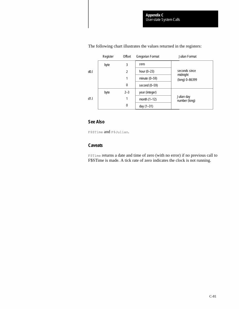
User-state System CallsAppendix C
C-81
The following chart illustrates the values returned in the registers:
Register
d0.l
(long) 0–86399
day (1–31)
Julian daymonth (1–12)d1.l
year (integer)byte
second (0–59)
minute (0–59)
seconds sincehour (0–23)
zero byte
Julian FormatGregorian Format
2–3
1
0
0
1
2
3
midnight
number (long)
Offset
See Also
F$STime and F$Julian .
Caveats
F$Time returns a date and time of zero (with no error) if no previous call toF$STime is made. A tick rate of zero indicates the clock is not running.
User-state System CallsAppendix C
C-82
Install User Trap Handler Module
ASM Call
OS9 F$TLink
Input
d0.w = User Trap Number (1–15)
d1.l = Optional memory override
(a0) = Module name pointer
If (a0)=0 or [(a0)]=0, trap handler is unlinked.
Other parameters may be required for specific
trap handlers.
Output
(a0) = Updated past module name
(a1) = Trap library execution entry point
(a2) = Trap module pointer
Other values may be returned by specific trap handlers
Error Output
cc = Carry bit set
d1.w = Appropriate error code
Function
You can use user traps as a convenient way to link into a standard set oflibrary routines at execution time. This provides the advantage of keepinguser programs small, and automatically updating programs that use thelibrary code if it is changed (without having to re-compile or re-link theprogram itself). Most Microware utilities use one or more trap libraries.
F$TLink attempts to link, or load, the named module, installing a pointerto it in the user’s process descriptor for subsequent use in trap calls. If atrap module already exists for the specified trap code, an error is returned.OS9 allocates and initializes static storage for the trap handler, if necessary.You can remove traps by passing a null pointer.
A user program calls a trap routine using the following assemblylanguage directive:
tcall N,Function
F$TLink
User-state System CallsAppendix C
C-83
This is the equivalent to:
trap #N
dc.w Function
“N” can be 1 to 15 (specifying which user trap vector to use). The functioncode is not used by OS-9, except that it is passed to the trap handler, andthe program counter is skipped past it.
F$TLink allows the program to delay installation of the handler until a trapis actually used in the program. If a user program executes a user trap callbefore the corresponding F$TLink call has been made, the system executesthe user’s default trap exception entry point (specified in the moduleheader) if one exists.
See Also
Chapter 5 on User Trap Handlers.
Caveat
System-state processes should not attempt to use trap handlers.

User-state System CallsAppendix C
C-84
Translate Memory Address
ASM Call
OS9 F$Trans
Input
d0.l = size of block to translate
d1.l = mode: 0 – local CPU address to external bus addr
1 – external bus address to local CPU addr
(a0) = address of block
Output
d0.l = size of block translated
(a0) = translated address of block
Error Output
cc = Carry bit set
d1.w = Appropriate error code
Function
On systems with dual-ported memory, a memory location may appear atdifferent addresses depending upon whether it is accessed via the “local”CPU bus or the system’s external bus. You can use the F$Trans request totranslate an address to or from its external bus address.
F$Trans is used when the external bus address must be passed to hardwaredevices, such as DMA-type controllers. Using the local CPU bus address isfaster and reduces the traffic on the external bus. Generally, you shouldonly use the system’s external bus address if it is not possible to use thelocal CPU bus address.
If the specified source block is non-linear with respect to its destinationmapping, F$Trans returns the maximum number of bytes accessible at thetranslated address. In this case, subsequent calls to F$Trans must be madeuntil the entire block has been successfully translated. This is rare, sinceOS-9’s memory management routines do not allocate non-linear blocks.
See Also
OS-9 Technical Overview, Chapter 2, sections on Init module memorydefinitions and Colored Memory.
Possible Errors
E$UnkSvc , E$Param, and E$IBA .
F$Trans
User-state System CallsAppendix C
C-85
User Accounting
ASM Call
OS9 F$UAcct
Input
d0.w = Function code (F$Fork, F$Chain, F$Exit)
(a0) = Process descriptor pointer
Output
None
Error Output
cc = carry bit set
d1.w = error code if error
Function
F$UAcct is a user-defined system call which may be installed by an OS9P2module. It is called in system state at the beginning and end of everyprocess, in other words, whenever F$Fork, F$Chain, or F$Exit is executed.
The kernel’s fork and chain routines make an F$UAcct request just beforea new process is inserted in the active queue. Since the new process isready to execute, its user number, priority, primary module, parameters,etc. are known to F$UAcct. This provides a variety of opportunities for aF$UAcct routine. For example:
A system administrator could keep track of every program run and whoran what program.
F$UAcct could automatically lower the priority of particular programs.
F$UAcct could keep a log of everything a specific user does.
Important: If F$UAcct returns an error during F$Fork, the new processterminates with the error code in d1.w.
OS-9’s process termination routine makes a F$UAcct request just before aprocess’s resources are returned to the system. The process descriptorcontains information about how much CPU time was consumed, how
F$UAcct
User-state System CallsAppendix C
C-86
many bytes were read or written, how many system calls were made, etc.Once again, F$UAcct could be used to record or react to this information.The system ignores any F$UAcct error returned at the end of a process.
Important: The values in all registers except d0 and d1 must be preserved.
See Also
F$SSvc; OS-9 Technical Overview, Chapter 2 (section on installingsystem-state routines).
Possible Errors
E$UnkSvc and E$Param.
User-state System CallsAppendix C
C-87
Unlink Module by Address
ASM Call
OS9 F$UnLink
Input
(a2) = Address of the module header
Output
None
Error Output
cc = Carry bit set
d1.w = Appropriate error code
Function
F$UnLink tells OS-9 that the module is no longer needed by the callingprocess. The module’s link count is decremented. When the link countequals zero, the module is removed from the module directory and itsmemory is de-allocated. When several modules are loaded together as agroup, modules are only removed when the link count of all modules in thegroup have zero link counts.
Device driver modules in use and certain system modules cannotbe unlinked.
See Also
F$UnLoad
Caveats
Repetitive UnLink calls to the same module artificially lower its linkcount, regardless of the number of current users. If the link count becomeszero while the module is being used, it is removed from the moduledirectory and its memory de-allocated. This causes severe problems forwhoever is currently using the module, and may crash the system.
F$UnLink
User-state System CallsAppendix C
C-88
Unlink Module by Name
ASM Call
OS9 F$UnLoad
Input
d0.w = Module type/language
(a0) = Module name pointer
Output
(a0) = Updated past module name
Error Output
cc = Carry bit set
d1.w = Appropriate error code
Function
F$UnLoad locates the module in the module directory, decrements its linkcount, and removes it from the directory if the count reaches zero. Notethat this call differs from F$UnLink in that the pointer to the module nameis supplied rather than the address of the module header.
See Also
F$UnLink
Caveat
Repetitive UnLoad calls to the same module artificially lower its linkcount, regardless of how many users are currently using it. If the link countbecomes zero while the module is being used, it is removed from themodule directory and its memory de-allocated. This causes severeproblems for whoever is currently using the module, and may crashthe system.
F$UnLoad
User-state System CallsAppendix C
C-89
Wait For Child Process to Terminate
ASM Call
OS9 F$Wait
Input
None
Output
d0.w = Terminating child process’s ID
d1.w = Child process’s exit status code
Error Output
cc = Carry bit set
d1.w = Appropriate error code
Function
F$Wait causes the calling process to deactivate until a child processterminates by executing a F$Exit system call, or otherwise is terminated.The child’s ID number and exit status are returned to the parent. If thechild process died due to a signal, the exit status word (register d1) is thesignal code.
If the caller has several child processes, the caller is activated when thefirst one dies, so one Wait system call is required to detect termination ofeach child.
If a child process died before the Wait call, the caller is reactivatedimmediately. Wait returns an error only if the caller has no child processes.
See Also
F$Exit , F$Send, and F$Fork .
Caveats
The process descriptors for child processes are not returned to free memoryuntil their parent process does a F$Wait system call or terminates.
If a signal is received by a process waiting for children to terminate, it isactivated. In this case, d0.w contains zero, since no child processhas terminated.
Possible Errors
E$NoChld
F$Wait

User-state System CallsAppendix C
C-90
I/O System CallsAppendix C
C-91
Attach a New Device to the System
ASM Call
OS9 I$Attach
Input
d0.b = Access mode (Read_, Write_, Updat_)
(a0) = Device name pointer
Output
(a2) = Address of the device table entry
Error Output
cc = Carry bit set
d1.w = Appropriate error code
Function
I$Attach causes an I/O device to become known to the system. You use itto attach a new device to the system, or to verify that it is already attached.
The device’s name string is used to search the system module directory tosee if a device descriptor module with the same name is in memory (this isthe name by which the device is known). The descriptor module containsthe name of the device’s file manager, device driver, and otherrelated information.
If the descriptor is found and the device is not already attached, OS-9 linksto its file manager and device driver. It then places their addresses in a newdevice table entry. Any permanent storage needed by the device driver isallocated, and the driver’s initialization routine is called to initialize thehardware. If the device has already been attached, it is not re-initialized.
The access mode parameter may be used to verify that subsequent readand/or write operations are permitted. An Attach system call is notrequired to perform routine I/O. It does not reserve the device in question;I$Attach simply prepares it for subsequent use by any process.
The kernel attaches all devices at open, and detaches them at close.
I$Attach
I/O System CallsAppendix C
C-92
Important: Attach and Detach for devices are similar to Link and Unlinkfor modules; they are usually used together. However, system performancecan improve slightly if all devices are attached at startup. This incrementseach device’s use count and prevents the device from being re-initializedevery time it is opened. This also has the advantage of allocating the staticstorage for devices all at once, which minimizes memory fragmentation. Ifthis is done, the device driver termination routine is never executed.
See Also
I$Detach
Possible Errors
E$DevOvf , E$BMode, E$DevBsy, and E$MemFul.
I/O System CallsAppendix C
C-93
Change Working Directory
ASM Call
OS9 I$ChgDir
Input
d0.b = Access mode (read/write/exec)
(a0) = Address of the pathlist
Output
(a0) = Updated past pathname
Error Output
cc = Carry bit set
d1.w = Appropriate error code
Function
ChgDir changes a process’s working directory to another directory filespecified by the pathlist. Depending on the access mode given, either theexecution or the data directory (or both) may change. The file specifiedmust be a directory file, and the caller must have access permission for thespecified mode.
ACCESS MODES: 1 = Read2 = Write3 = Update (read and write)4 = Execute
If the access mode is read, write, or update, the current data directorychanges. If the access mode is execute, the current execution directorychanges. Both can change simultaneously.
Important: The shell CHD directive uses UPDATE mode, which meansyou must have both read and write permission to change directories fromthe shell. This is a recommended practice.
Possible Errors
E$BPNam and E$BMode.
I$ChgDir
I/O System CallsAppendix C
C-94
Close a Path to a File/Device
ASM Call
OS9 I$Close
Input
d0.w = Path number
Output
None
Error Output
cc = Carry bit set
d1.w = Appropriate error code
Function
I$Close terminates the I/O path specified by the path. The path number isno longer valid for any OS-9 calls unless it becomes active again throughan Open, Create, or Dup system call. When pathlists to non-sharabledevices are closed, the devices become available to other requestingprocesses. If this is the last use of the path (that is, it has not been inheritedor duplicated by I$Dup), all OS-9 internally managed buffers anddescriptors are deallocated.
Important: The OS-9 F$Exit service request automatically closes anyopen paths. By convention, standard I/O paths are not closed unless it isnecessary to change the files/devices they correspond to.
See Also
I$Detach
Caveats
I$Close does an implied I$Detach call. If this causes the device use countto become zero, the device termination routine is executed.
Possible Errors
E$BPNum
I$Close

I/O System CallsAppendix C
C-95
Create a Path to New File
ASM Call
OS9 I$Create
Input
d0.b = Access mode (S, I, E, W, R)
d1.w = File attributes (access permission)
d2.l = Initial allocation size (optional)
(a0) = Pathname pointer
Output
d0.w = Path number
(a0) = Updated past the pathlist
Error Output
cc = Carry bit set
d1.w = Appropriate error code
Function
I$Create creates a new file. On multi-file devices, the new file name isentered in the directory structure, and Create is synonymous with Open.
The access mode parameter passed in register d0.b must have the write bitset if any data is to be written to the file. The file is given the attributespassed in the register d1.w. The individual bits are defined as follows:
Mode bits (d0.w) Attribute bits (d1.w)
0 = read 0 = owner read permit
1 = write 1 = owner write permit
2 = execute 2 = owner execute permit
5 = initial file size 3 = public read permit
6 = single user 4 = public write permit
5 = public execute permit
6 = non-sharable file
I$Create
I/O System CallsAppendix C
C-96
If the execute bit (bit 2) of the access mode byte is set, directory searchingbegins with the working execution directory instead of the workingdata directory.
The path number returned by OS-9 identifies the file in subsequent I/Oservice requests until the file is closed.
WRITE automatically allocates file space for the file. The SETSTAT call(SS_Size) explicitly allocates file space. If the size bit (bit 5) is set, aninitial file size estimate may be passed in d2.l.
An error occurs if the pathlist specifies a file name that already exists. Youcannot use I$Create to make directory files (see I$MakDir).
Create causes an implicit I$Attach call. If the device has not previouslybeen attached, the device’s initialization routine is executed.
See Also
I$Attach , I$Open , I$Close , and I$MakDir .
Caveats
The caller is made the owner of the file. To maintain compatibility withOS9/6809 disk formats, there is only space for two bytes of owner ID. TheLS byte of the user’s group and the LS byte of the user’s ID are used as theowner ID. All user’s with the same group ID may access the file asthe owner.
If an initial file size is specified with I$Create, the exact amount specifiedmay not be allocated. You must execute a SS_Size SetStat after creatingthe file to ensure that sufficient space was allocated.
Possible Errors
E$PthFul and E$BPNam.
I/O System CallsAppendix C
C-97
Delete a File
ASM Call
OS9 I$Delete
Input
d0.b = Access mode (read/write/exec)
(a0) = Pathname pointer
Output
(a0) = Updated past pathlist
Error Output
cc = Carry bit set
d1.w = Appropriate error code
Function
I$Delete deletes the file specified by the pathlist. The caller must havenon-sharable write access to the file (the file may not already be open) oran error results. An attempt to delete a non-multifile device results inan error.
The access mode is used to specify the data or execution directory (but notboth) in the absence of a full pathlist. If the access mode is read, write, orupdate, the current data directory is assumed. If the execute bit is set, thecurrent execution directory is assumed. Note that if a full pathlist isspecified, that is, a pathlist beginning with a slash (/), the access modeis ignored.
See Also
I$Detach , I$Attach , I$Create , and I$Open .
Possible Errors
E$BPNam
I$Delete
I/O System CallsAppendix C
C-98
Remove a Device From the System
ASM Call
OS9 I$Detach
Input
(a2) = Address of the device table entry
Output
None
Error Output
cc = Carry bit set
d1.w = Appropriate error code
Function
I$Detach removes a device from the system device table, if not in use byany other process. If this is the last use of the device, the device driver’stermination routine is called, and any permanent storage assigned to thedriver is de-allocated. The device driver and file manager modulesassociated with the device are unlinked and may be lost if not in use byanother process. It is crucial for the termination routine to remove thedevice from the IRQ system.
You must use the I$Detach service request to un-attach devices that wereattached with the I$Attach service request. Both of these are used mainlyby the kernel and are of limited use to the typical user. SCF also usesAttach/Detach to set up its second (echo) device.
Most devices are attached at startup and remain attached. Seldom useddevices can be attached to the system and used for a while, then detachedto free system resources when no longer needed.
See Also
I$Attach and I$Close .
Caveats
If an invalid address is passed in (a2), the system may crash or undergosevere damage.
I$Detach

I/O System CallsAppendix C
C-99
Duplicate a Path
ASM Call
OS9 I$Dup
Input
d0.w = Path number of path to duplicate
Output
d0.w = New number for the same path
Error Output
cc = Carry bit set
d1.w = Appropriate error code
Function
Given the number of an existing path, I$Dup returns a synonymous pathnumber for the same file or device. I$Dup always uses the lowest availablepath number. For example, if you do I$Close on path #0, then do I$Dup onpath #4, path #0 is returned as the new path number. In this way, thestandard I/O paths may be manipulated to contain any desired paths.
The shell uses this service request when it redirects I/O. Service requestsusing either the old or new path numbers operate on the same fileor device.
Caveats
This only increments the use count of a path descriptor and returns asynonymous path number. The path descriptor is NOT copied. It is usuallynot a good idea for more than one process to be doing I/O on the same pathconcurrently. On RBF files, unpredictable results may occur.
Possible Errors
E$PthFul and E$BPNum.
I$Dup
I/O System CallsAppendix C
C-100
Get File/Device Status
ASM Call
OS9 I$GetStt
Input
d0.w = Path number
d1.w = Function code
Others = dependent on function code
Output
Dependent on function code
Error Output
cc = Carry bit set
d1.w = Appropriate error code
Function
This is a wild card call used to handle individual device parameters that arenot uniform on all devices, or are highly hardware dependent. The exactoperation of this call depends on the device driver and file managerassociated with the path.
A typical use is to determine a terminal’s parameters (echo on/off, deletecharacter, etc.). It is commonly used in conjunction with the SetStt call,which sets the device operating parameters.
The mnemonics for the status codes are found in the relocatable librarysys.l or usr.l. Codes 0-127 are reserved for Microware use. The remainingcodes and their parameter passing conventions are user definable (see theOS-9 Technical Overview section on device drivers in Chapter 3).Presently defined function codes are listed below.
Possible Errors
E$BPNum
I$GetStt

I/O System CallsAppendix C
C-101
Return Device Name (ALL)
Input
d0.w = Path number
d1.w = #SS_DevNm function code
(a0) = Address of 32 byte area for device name
Output
Device name in 32 byte storage area, null terminated
Test for End of File (RBF, SCF, PIPE)
Input
d0.w = Path number
d1.w = #SS_EOF function code
Output
d1.l = 0 If not EOF, (SCF never returns EOF)
Error Output
cc = Carry bit set
d1.w = Appropriate error code (E$EOF, if end of file)
SS_DevNum
SS_EOF
I/O System CallsAppendix C
C-102
Return File Descriptor (CDFM)
Input
d0.w = Path number
d1.w = #SS_CDFD function code
d2.w = Number of bytes to copy
(a0) = Pointer to buffer area for file
descriptor
Output
None
Error Output
cc = Carry bit set
d1.w = Appropriate error code
Function
SS_CDFD reads the file descriptor describing the path number. The filedescriptor may be read for information purposes only, as there are no userchangeable parameters.
Read File Descriptor Sector (RBF, PIPE)
Input
d0.w = Path number
d1.w = #SS_FD function code
d2.w = Number of bytes to copy(<=logical sector size of
media)
(a0) = Address of buffer area for FD
Output
File descriptor copied into buffer
Function
Use SS_FD to inspect the file descriptor information (for example,FD_OWN and FD_DAT) and the file segment list.
SS_CDFD
SS_FD

I/O System CallsAppendix C
C-103
Get Specified File Descriptor Sector (RBF)
Input
d0.w = Path number
d1.w = #SS_FDInf function code
d2.w = Number of bytes to copy (<=256)
d3.l = FD sector address
(a0) = Address of buffer area for FD
Output
File descriptor copied into buffer
Important: If SS_FDInf is called in user state, the caller must be asuper-group user. If it is called in system state, the caller does not have tobe a super-group user.
Return Amount of Free Space on Device (NRF, NVRAM file mgr.)
Input
d0.l = Path number
d1.w = #SS_Free function code
Output
d0.l = Size of free space on device, in bytes
SS_FDInf
SS_Free

I/O System CallsAppendix C
C-104
Read PD_OPT: The Path Descriptor Option Section. (All)
Input
d0.w = Path number
d1.w = #SS_Opt function code
(a0) = Address to put a 128 byte status packet
Output
Status packet copied to buffer
Error Output
cc = Carry bit set
d1.w = Appropriate error code
Function
SS_Opt reads the option section of the path descriptor and copies it into the128 byte area pointed to by (a0). It is typically used to determine thecurrent settings for echo, auto line feed, etc. For a complete description ofthe status packet, refer to Chapter 3 of the OS-9 Technical Overview, thesection on file manager path descriptors.
Get Current File Position (RBF, PIPE)
Input
d0.w = Path number
d1.w = #SS_Pos function code
Output
d2.1 = Current file position
Error Output
cc = Carry bit set
d1.w = Appropriate error code
SS_Opt
SS_Pos
I/O System CallsAppendix C
C-105
Test for Data Ready (RBF, SCF, PIPE)
Input
d0.w = Path number
d1.w = #SS_Ready function code
Output
d1.l = Number of input characters available on SCF or pipe
devices.
RBF devices always return carry clear, d1.l=1
Error Output
cc = Carry bit set
d1.w = Appropriate error code (E$NotRdy if no data is
available)
Return Current File Size (RBF, PIPE)
Input
d0.w = Path number
d1.w = #SS_Size function code
Output
d2.l = Current file size
Error Output
cc = Carry bit set
d1.w = Appropriate error code
SS_Ready
SS_Size

I/O System CallsAppendix C
C-106
Query Support for Variable Logical Sector Sizes (RBF)
Input
d0.w = path number
d1.w – #SS_VarSect function code
Output
None
Function
SS_VarSect is an internal call between RBF and a driver. If the driver doesnot return an error, the logical sector size of the media is specified inPD_SSize. If the driver returns an error, and the error is E$UnkSvc, RBFsets the path’s logical sector size to 256 bytes and ignores PD_SSize. If anyother error is returned, the path open is aborted and the error is returned tothe caller.
SS_VarSect

I/O System CallsAppendix C
C-107
Make a New Directory
ASM Call
OS9 I$MakDir
Input
d0.b = Access mode (see below)
d1.w = Access permissions
d2.l = Initial Allocation Size (Optional)
(a0) = Pathname pointer
Output
(a0) = Updated past pathname
Error Output
cc = Carry bit set
d1.w = Appropriate error code
Function
I$MakDir is the only way to create a new directory file. It creates andinitializes a new directory as specified by the pathlist. The new directoryfile contains no entries, except for an entry for itself (specified by a dot (.))and its parent directory (specified by double dot (..)). Makdir fails onnon-multi-file devices. If the execution bit is set, OS-9 begins searching forthe file in the working execution directory (unless the pathlist begins witha slash).
The caller is made the owner of the directory. MakDir does not return apath number because directory files are not opened by this request (useI$Open to do so). The new directory automatically has its directory bit setin the access permission attributes. The remaining attributes are specifiedby the bytes passed in register d1.w which have individual bits defined aslisted below (if the bit is set, access is permitted):
Mode bits (d0.w) Attribute bits (d1.w)
0 = read 0 = owner read permit1 = write 1 = owner write permit2 = execute 2 = owner execute permit5 = initial directory size 3 = public read permit7 = directory 4 = public write permit
5 = public execute permit6 = non-sharable file7 = directory
Possible Errors
E$BPNam and E$CEF.
I$MakDir

I/O System CallsAppendix C
C-108
Open a Path to a File or Device
ASM Call
OS9 I$Open
Input
d0.b = Access mode (D S E W R)
(a0) = Pathname pointer
Output
d0.w = Path number
(a0) = Updated past pathname
Error Output
cc = Carry bit set
d1.w = Appropriate error code
Function
I$Open opens a path to an existing file or device as specified by thepathlist. A path number is returned which is used in subsequent servicerequests to identify the path. If the file does not exist, an error is returned.
The access mode parameter specifies which subsequent read and/or writeoperations are permitted as follows (if the bit is set, access is permitted):
Mode Bits0 = read1 = write2 = execute6 = open file for non sharable use7 = open directory file
I$Open
I/O System CallsAppendix C
C-109
Important: A non-directory file may be opened with no bits set. Thisallows you to examine the attributes, size, etc. with the GetStt system call,but does not permit any actual I/O on the path.
For RBF devices, use read mode instead of update if the file is not going tobe modified. This inhibits record locking, and can dramatically improvesystem performance if more than one user is accessing the file. The accessmode must conform to the access permissions associated with the file ordevice (see I$Create).
If the execution bit mode is set, OS-9 begins searching for the file in theworking execution directory (unless the pathlist begins with a slash).
If the single user bit is set, the file is opened for non-sharable access evenif the file is sharable.
Files can be opened by several processes (users) simultaneously. Deviceshave an attribute that specifies whether or not they are sharable on anindividual basis.
Open always uses the lowest path number available for the process.
See Also
I$Attach , I$Create and I$Close .
Caveats
Directory files may be opened only if the Directory bit (bit 7) is set in theaccess mode.
Possible Errors
E$PthFul , E$BPNam, E$Bmode, E$FNA, E$PNNF, and E$Share .

I/O System CallsAppendix C
C-110
Read Data From a File or Device
ASM Call
OS9 I$Read
Input
d0.w = Path number
d1.l = Maximum number of bytes to read
(a0) = Address of input buffer
Output
d1.l = Number of bytes actually read
Error Output
cc = Carry bit set
d1.w = Appropriate error code
Function
I$Read reads a specified number of bytes from the specified path number.The path must previously have been opened in read or update mode. Thedata is returned exactly as read from the file/device, without additionalprocessing or editing such as backspace, line delete, etc. If there is notenough data in the file to satisfy the read request, fewer bytes are read thanrequested, but an end of file error is not returned.
After all data in a file has been read, the next I$Read service requestreturns an end of file error.
See Also
I$ReadLn
I$Read

I/O System CallsAppendix C
C-111
Caveats
The keyboard X-ON/X-OFF characters may be filtered out of the inputdata on SCF-type devices unless the corresponding entries in the pathdescriptor are set to zero. You may wish to modify the device descriptor sothat these values in the path descriptor are initialized to zero when the pathis opened. SCF devices usually terminate the read when a carriage returnis reached.
For RBF devices, if the file is open for update, the record read is lockedout. See the Record Locking section in the RBF chapter of the OS-9Technical I/O Manual.
The number of bytes requested is read unless:
the end-of-file is reached an end-of-record occurs (SCF only) an error condition occurs
Possible Errors
E$BPNum, E$Read, E$BMode, and E$EOF.
I/O System CallsAppendix C
C-112
Read a Text Line With Editing
ASM Call
OS9 I$ReadLn
Input
d0.w = Path number
d1.l = Maximum number of bytes to read
(a0) = Address of input buffer
Output
d1.l = Actual number of bytes read
Error Output
cc = Carry bit set
d1.w = Appropriate error code
Function
ReadLn is similar to Read except it reads data from the input file or deviceuntil an end-of-line character is encountered. ReadLn also causes lineediting to occur on SCF-type devices. Line editing refers to backspace, linedelete, echo, automatic line feed, etc. Some devices (SCF) may limit thenumber of bytes that may be read with one call.
SCF requires that the last byte entered be an end-of-record character(normally carriage return). If more data is entered than the maximumspecified, it is not accepted and a PD_OVF character (normally bell) isechoed. For example, a ReadLn of exactly one byte accepts only a carriagereturn to return without error and beeps when other keys are pressed.
After all data in a file has been read, the next I$ReadLn service requestreturns an end of file error.
See Also
I$Read
Possible Errors
E$BPNum, E$Read, and E$BMode.
I$ReadLn
I/O System CallsAppendix C
C-113
Reposition the Logical File Pointer
ASM Call
OS9 I$Seek
Input
d0.w = Path number
d1.l = New position
Output
None
Error Output
cc = Carry bit set
d1.w = Appropriate error code
Function
I$Seek repositions the path’s file pointer which is the 32-bit address of thenext byte in the file to be read or written. I$Seek usually does not initiateany physical positioning of the media.
You can perform a Seek to any value even if the file is not large enough.Subsequent writes automatically expand the file to the required size (ifpossible), but reads return an end-of-file condition.
Important: A Seek to address zero is the same as a rewind operation.
Seeks to non-random access devices are usually ignored and returnwithout error.
Caveats
On RBF devices, seeking to a new disk sector causes the internal sectorbuffer to be rewritten to disk if it has been modified. Seek does not changethe state of record locks. Beware of seeking to a negative position. RBFtakes negatives as large positive numbers.
Possible Errors
E$BPNum
I$Seek

I/O System CallsAppendix C
C-114
Set File/Device Status
ASM Call
OS9 I$SetStt
Input
d0.w = Path number
d1.w = Function code
Others = Function code dependent
Output
Function code dependent
Error Output
cc = Carry bit set
d1.w = Appropriate error code
Function
This is a “wild card” system call used to handle individual deviceparameters that are not uniform on all devices or are highly hardwaredependent. The exact operation of this call depends on the device driverand file manager associated with the path.
A typical use is to set a terminal’s parameters for backspace character,delete character, echo on/off, null padding, paging, etc. It is commonlyused in conjunction with the GetStt service request which reads thedevice’s operating parameters.
The mnemonics for the status codes are found in the relocatable librarysys.l or usr.l. Codes 0-127 are reserved for Microware use. The remainingcodes and their parameter passing conventions are user definable (see theOS-9 Technical Overview section on device drivers in Chapter 3).Presently defined function codes are listed below.
Possible Errors
E$BPNum
I$SetStt

I/O System CallsAppendix C
C-115
Set the File Attributes (RBF, PIPE)
Input
d0.w = Path number
d1.w = #SS_Attr function code
d2.w = New attributes
Output
None
Function
SSAttr changes a file’s attributes to the new value, if possible. It is notpermitted to set the dir bit of a non-directory file, or to clear the dir bit of anon-empty directory.
Notifies Driver That a Path Has Been Closed (SCF, RBF, SBF)
Input
d0.w = path number
d1.w = SS_Close function code
Output
None
Function
SS_Close is an internal call for drivers.
SS_Attr
SS_Close

I/O System CallsAppendix C
C-116
Sends Signal When Data Carrier Detect Line Goes False (SCF)
Input
d0.w = path number
d1.w = SS_DCOff function code
d2.w = Signal code to be sent
Output
None
Function
When a modem has finished receiving data from a carrier, the Data CarrierDetect line goes false. SS_DCOff sends a signal code when this happens.SS_DCOn sends a signal when the line goes true.
Sends Signal When Data Carrier Detect Line Goes True (SCF)
Input
d0.w = path number
d1.w = SS_DCOn function code
d2.w = Signal code to be sent
Output
None
Function
When a modem receives a carrier, the Data Carrier Detect line goes true.SS_DCOn sends a signal code when this happens. SS_DCOff sends a signalwhen the line goes false.
SS_DCOff
SS_DCon
I/O System CallsAppendix C
C-117
Disables RTS Line (SCF)
Input
d0.w = path number
d1.w = SS_DsRTS function code
Output
None
Function
SS_DsRTS tells the driver to negate the RTS hardware handshake line.
Enables RTS Line (SCF)
Input
d0.w = path number
d1.w = SS_EnRTS function code
Output
None
Function
SS_EnRTS tells the driver to negate the RTS hardware handshake line.
SS_DsRTS
SS_EnRTS
I/O System CallsAppendix C
C-118
Erase Tape (SBF)
Input
d0.w = path number
d1.w = SS_Feed function code
d2.l = # of blocks to erase
Output
None
Function
SS_Feed erases a portion of the tape. The amount of tape erased dependson the capabilities of the hardware used. SBF attempts to use thefollowing: If –1 is passed in d2, SBF erases until the end-of-tape isreached. If d2 receives a positive parameter, SBF erases the amount of tapeequivalent to that number of blocks. This depends on both the hardwareused and the driver.
Write File Description Sector (RBF)
Input
d0.w = Path Number
d1.w = #SS_FD function code
(a0) = Address of FD sector image
Output
None
Function
SS_FD changes FD sector data. The path must be open for write.
Important: You can only change FD_OWN, FD_DAT, and FD_Creat.These are the only fields written back to disk. Only the super user canchange the file’s owner ID.
SS_FD should normally be used with GetStat (SS_FD) to read the FDbefore attempting to change FD sector data.
SS_Feed
SS_FD
I/O System CallsAppendix C
C-119
Lock Out a Record (RBF)
Input
d0.w = Path Number
d1.w = #SS_Lock function code
d2.l = Lockout size
Output
None
Function
SS_Lock locks out a section of the file from the current file pointer positionup to the specified number of bytes.
If 0 bytes are requested, all locks are removed (Record Lock, EOF Lock,and File Lock).
If $FFFFFFFF bytes are requested, then the entire file is locked outregardless of where the file pointer is. This is a special type of file lock thatremains in effect until released by SS_Lock(0), a read or write of zerobytes, or the file is closed.
There is no way to gain file lock using only read or write system calls.
Notifies Driver That a Path Has Been Opened
Input
d0.w = path number
d1.w = SS_Open function code
Output
None
Function
SS_Open is an internal call for drivers.
SS_Lock
SS_Open
I/O System CallsAppendix C
C-120
Write Option Selection of Path Descriptor (ALL)
Input
d0.w = Path number
d1.w = #SS_Opt function code
(a0) = Address of a 128 byte status packet
Output
None
Function
SS_Opt writes the option section of the path descriptor from the 128 bytestatus packet pointed to by (a0). It is typically used to set the deviceoperating parameters (echo, auto line feed, etc.). This call is handled by thefile managers, and only copies values that are appropriate to be changed byuser programs.
Release Device (SCF, PIPE)
Input
d0.w = path number
d1.w = SS_Relea function code
Output
None
Function
SS_Relea releases the device from any SS_SSig, SS_DCOn, orSS_DCOff requests made by the calling process on this path.
SS_Opt
SS_Relea
I/O System CallsAppendix C
C-121
Restore Head to Track Zero (RBF, SBF)
Input
d0.w = Path number
d1.w = #SS_Reset function code
Output
None
Function
For RBF, this directs the disk head to track zero. It is used for formattingand for error recovery. For SBF, this rewinds the tape.
Skip Tape Marks (SBF)
Input
d0.w = path number
d1.w = SS_RFM function code
d2.l = # of tape marks
Output
None
Function
SS_RFM skips the number of tape marks specified in d2. If d2 is negative,the tape is rewound the specified number of marks.
SS_Reset
SS_RFM
I/O System CallsAppendix C
C-122
Set File Size (RBF, PIPE)
Input
d0.w = Path number
d1.w = #SS_Size function code
d2.l = Desired file size
Output
None
Function
SS_Size sets the file’s size.
For pipe files, you can use SS_Size to reset the pipe path (d2.1=0),provided the pipe has no active readers or writers. Any other value in d2.1is ignored.
Skip Blocks (SBF)
Input
d0.w = path number
d1.w = SS_Skip function code
d2.l = # of blocks to skip
Output
None
Function
SS_Skip skips the number of blocks specified in d2. If the number isnegative, the tape is rewound the specified number of blocks.
SS_Size
SS_Skip

I/O System CallsAppendix C
C-123
Send Signal on Data Ready (SCF, PIPE)
Input
d0.w = Path number
d1.w = SS_SSig function code
d2.w = User defined signal code
Output
None
Function
SS_SSig sets up a signal to send to a process when an interactive device orpipe has data ready. SS_SSig must be reset each time the signal is sent. Thedevice or pipe is considered busy and returns an error if any read requestarrives before the signal is sent. Write requests to the device are allowed inthis state.
Wait Specified Number of Ticks for Record Release (RBF)
Input
d0.w = path number
d1.w = #SS_Ticks function code
d2.l = Delay interval
Output
None
Function
Normally, if a read or write request is issued for a part of a file that islocked out by another user, RBF sleeps indefinitely until the conflictis removed.
You can use SS_Ticks to return an error (E$Lock) to the user program ifthe conflict still exists after the specified number of ticks have elapsed.
The delay interval is used directly as a parameter to RBF’s conflict sleeprequest. The value zero (RBF’s default) causes a sleep forever until therecord is released. A value of one means that if the record is not releasedimmediately, an error is returned. If the high order bit is set, the lower 31bits are converted from 256th of a second into ticks before sleeping. Thisallows programmed delays to be independent of the system clock rate.
SS_SSig
SS_Ticks
I/O System CallsAppendix C
C-124
Write Tape Marks (SBF)
Input
d0.w = path number d1.w = SS_WFM function code d2.l = # of tape marks
Output
None
Function
SS_WFM writes the number of tape marks specified in d2.
Write (Format) Track (RBF)
Input
d0.w = Path numberd1.w = #SS_WTrk function code (a0) = Address of track buffer For hard disks and “autosize” media, this table contains 1 logical sector of data (pattern $E5). For floppy disks, this table contains the track’s physical data.(a1) = Address of interleave table This table contains byte entries of LSN’s ordered to match the requested interleave offset. NOTE: This is a “logical” table and does not reflect the PD_SOffs base sector number.d2 = Track number d3.w = Side/density The low order byte has 3 bits which can be set: Bit 0 = SIDE (0=side zero;1=side one) Bit 1 = DENSITY (0=single;1=double) Bit 2 = TRACK DENSITY (0=single;1=double) The high order byte contains the side number. d4 = Interleave value
Output
None
Function
SS_Wtrk causes a format track operation (used with most floppy disks) tooccur. For hard or floppy disks with a “format entire disk” command, thisformats the entire media only when side 0 of the first accessable trackis specified.
SS_WFM
SS_WTrk

I/O System CallsAppendix C
C-125
Write Data to a File or Device
ASM Call
OS9 I$Write
Input
d0.w = Path number
d1.l = Number of bytes to write
(a0) = Address of buffer
Output
d1.l = Number of bytes actually written
Error Output
cc = Carry bit set
d1.w = Appropriate error code
Function
I$Write outputs bytes to a file or device associated with the path numberspecified. The path must have been opened or created in the write orupdate access modes.
Data is written to the file or device without processing or editing. If data iswritten past the present end-of-file, the file is automatically expanded.
See Also
I$Open , I$Create , and I$WritLn .
Caveats
On RBF devices, any record that was locked is released.
Possible Errors
E$BPNum, E$BMode, and E$Write .
I$Write

I/O System CallsAppendix C
C-126
Write a Line of Text With Editing
ASM Call
OS9 I$WritLn
Input
d0.w = Path number
d1.l = Maximum number of bytes to write
(a0) = Address of buffer
Output
d1.l = Actual number of bytes written
Error Output
cc = Carry bit set
d1.w = Appropriate error code
Function
I$WriteLn is similar to Write except it writes data until a carriage returncharacter or (d1) bytes are encountered. Line editing is also activated forcharacter-oriented devices such as terminals, printers, etc. The line editingrefers to auto line feed, null padding at end-of-line, etc.
The number of bytes actually written (returned in d1.l) does not reflect anyadditional bytes that may have been added by file managers or devicedrivers for device control. For example, if SCF appends a line feed andnulls after carriage return characters, these extra bytes are not counted.
See Also
I$Open , I$Create , and I$Write ; OS-9 Technical I/O Manual chapter onSCF Drivers (line editing).
Caveats
On RBF devices, any record that was locked is released.
Possible Errors
E$BPNum, E$BMode, and E$Write .
I$WritLn
System-state System CallsAppendix C
C-127
Set Alarm Clock
ASM Call
OS9 F$Alarm
Input
d0.l = Alarm ID (or zero)
d1.w = Function code
d2.l = Reserved, must be zero
d3.l = Time interval (or time)
d4.l = Date (when using absolute time)
(a0) = Register image
Output
d0.l = Alarm ID
Error Output
cc = Carry bit set
d1.w = Appropriate error code
Function
When called from system state, F$Alarm causes the execution of asystem-state subroutine at a specified time. It is provided for suchfunctions as turning off a disk drive motor if the disk is not accessed for aperiod of time.
The register image pointed to by register (a0) contains an image of theregisters to be passed to the alarm subroutine. The subroutine entry pointmust be placed in R$pc(a0). The register image is copied by the F$Alarmrequest into another buffer area and may re-used immediately forother purposes.
The alarm ID returned may be used to delete an alarm request.
The time interval is the number of system clock ticks (or 256ths of asecond) to wait before the alarm subroutine is executed. If the high orderbit is set, the low 31 bits are interpreted as 256ths of a second.
Important: All times are rounded up to the nearest clock tick.
F$Alarm
System-state System CallsAppendix C
C-128
The system automatically deletes a process’s pending alarms when theprocess dies.
The alarm function code is used to select one of the related alarmfunctions. Not all input parameters are always needed; each function isdescribed in the following pages.
The following function codes are supported:
Function code: Description:
A$Delete Remove a pending alarm request
A$Set Execute a subroutine after a specified time interval
A$Cycle Execute a subroutine at specified time intervals
A$AtDate Execute a subroutine at a Gregorian date/time
A$AtJul Execute a subroutine at Julian date/time
System-state alarm subroutines must conform to thefollowing conventions:
Input:
d0–d7 = caller’s registers (R$d0–R$d7(a5))
(a0)–(a3) = caller’s registers (R$a0–R$a3(a5))
(a4) = system process descriptor pointer*
(a5) = ptr to register image
(a6) = system global storage pointer
Output:
cc = carry set
d1.w = error code if error
Important: * The user number in the system process descriptor will havebeen temporarily changed to the user number of original F$Alarm request.The registers d0-d7 and (a0)-(a3) do not have to be preserved.
System-state System CallsAppendix C
C-129
Caveats
System-state alarms are executed by the system process at priority 65535.They may never perform any function that can result in any kind ofqueuing, such as F$Sleep, F$Wait, F$Load, F$Event (Ev$Wait), F$IOQu,or F$Fork. When such functions are required, the caller must provide aseparate process to perform the function, rather than an alarm.
ATTENTION: If an alarm execution routine suffers any kindof bus trap, address trap, or other hardware-related error, thesystem will crash.
See Also
F$Alarm User-State System Call
Possible Errors
E$UnkSvc , E$Param, E$MemFul, E$NoRAM, and E$BPAddr.
Remove a Pending Alarm Request
Input
d0.l = Alarm ID (or zero)
d1.w = A$Delete function code
Output
None
Function
A$Delete removes a cyclic alarm or any alarm that has not expired. If zerois passed as the alarm ID, all pending alarm requests for the current processare removed.
A$Delete
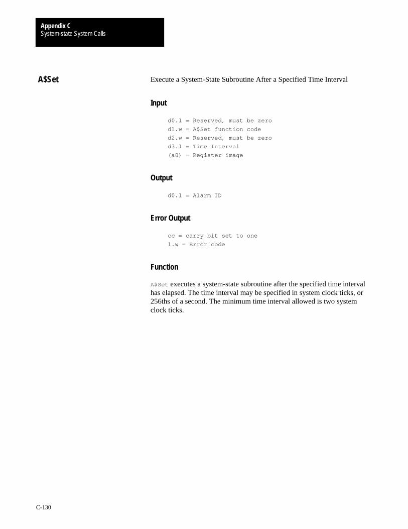
System-state System CallsAppendix C
C-130
Execute a System-State Subroutine After a Specified Time Interval
Input
d0.l = Reserved, must be zero
d1.w = A$Set function code
d2.w = Reserved, must be zero
d3.l = Time Interval
(a0) = Register image
Output
d0.l = Alarm ID
Error Output
cc = carry bit set to one
1.w = Error code
Function
A$Set executes a system-state subroutine after the specified time intervalhas elapsed. The time interval may be specified in system clock ticks, or256ths of a second. The minimum time interval allowed is two systemclock ticks.
A$Set

System-state System CallsAppendix C
C-131
Execute a System-State Subroutine Every
Input
d0.l = reserved, must be zero
d1.w = A$Cycle function code
d2.l = signal code
d3.l = time interval
Output
d0.l = alarm ID
Error Output
cc = carry bit set
d1.w = appropriate error code
Function
The cycle function is similar to the set function, except that the alarm isreset after it is sent. This causes periodic execution of asystem-state subroutine.
Caveat
Keep cyclic system-state alarms as fast as possible and schedule them withas long a cycle as possible to avoid consuming a large portion of availableCPU time.
A$Cycle

System-state System CallsAppendix C
C-132
Execute a System-State Subroutine at Gregorian Date/Time
Input
d0.l = Reserved, must be zero
d1.w = A$AtDate function code
d2.l = Reserved, must be zero
d3.l = Time (00hhmmss)
d4.l = Date (YYYYMMDD)
(a0) = Register image
Output
d0.l = alarm ID
Error Output
cc = carry bit set
d1.w = appropriate error code
Function
A$AtDate executes a system-state subroutine at a specific date and time.
Important: A$AtDate only allows you to specify time to the nearestsecond. However, it does adjust if the system’s date and time have changed(via F$STime). The alarm subroutine executes anytime the systemdate/time becomes greater than or equal to the alarm time.
A$AtDate
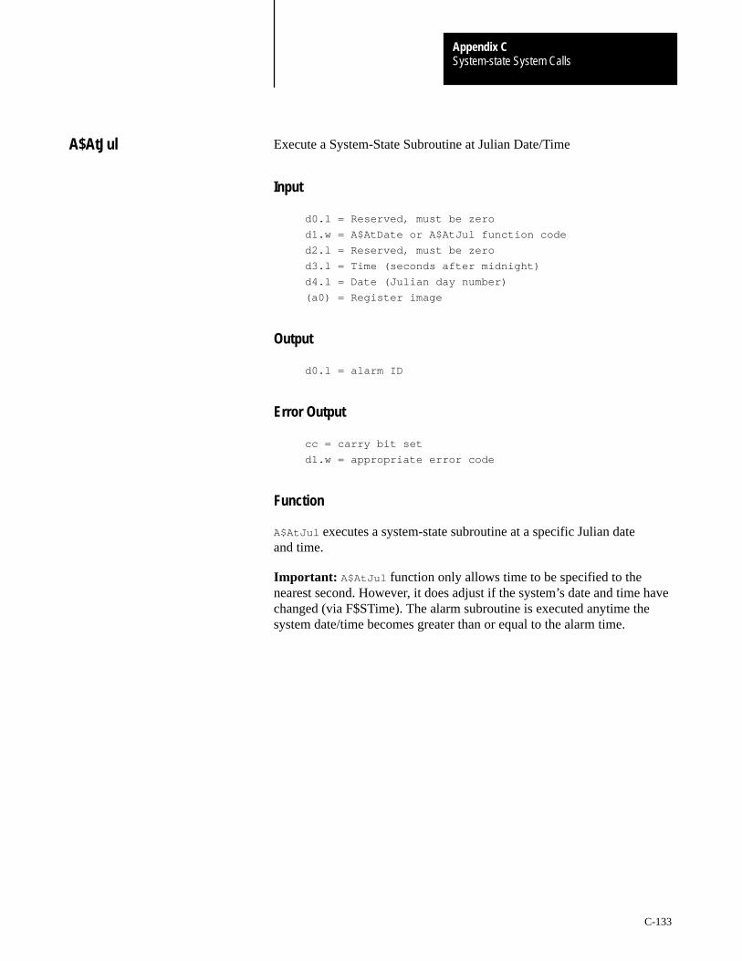
System-state System CallsAppendix C
C-133
Execute a System-State Subroutine at Julian Date/Time
Input
d0.l = Reserved, must be zero
d1.w = A$AtDate or A$AtJul function code
d2.l = Reserved, must be zero
d3.l = Time (seconds after midnight)
d4.l = Date (Julian day number)
(a0) = Register image
Output
d0.l = alarm ID
Error Output
cc = carry bit set
d1.w = appropriate error code
Function
A$AtJul executes a system-state subroutine at a specific Julian dateand time.
Important: A$AtJul function only allows time to be specified to thenearest second. However, it does adjust if the system’s date and time havechanged (via F$STime). The alarm subroutine is executed anytime thesystem date/time becomes greater than or equal to the alarm time.
A$AtJul

System-state System CallsAppendix C
C-134
Allocate Process/Path Descriptor
ASM Call
OS9 F$AllPD
Input
(a0) = process/path table pointer
Output
d0.w = process/path number
(a1) = pointer to process/path descriptor
Error Output
cc = Carry bit set
d1.w = error code if error
Function
F$AllPD allocates fixed-length blocks of system memory. It allocates andinitializes (to zeros) a block of storage and returns its address.
It can be used with F$FindPD and F$RetPD to perform simple memorymanagement. The system uses these routines to keep track of memoryblocks used for process and path descriptors. They can be used generallyfor similar purposes by creating a map table for the data allocations. Thetable must be initialized as follows:
Block Number Offset
$00000000 = unallocated
(address of block two)
(address of block one)
Blocksize
Max block (N)
(N)
(2)
(1)
(0)
(a0)
4*N
8
4
2
0
.
.
.
.
.
.
See Also
F$FindPD and F$RetPD.
Important: This is a privileged System-State service request.
F$AllPD
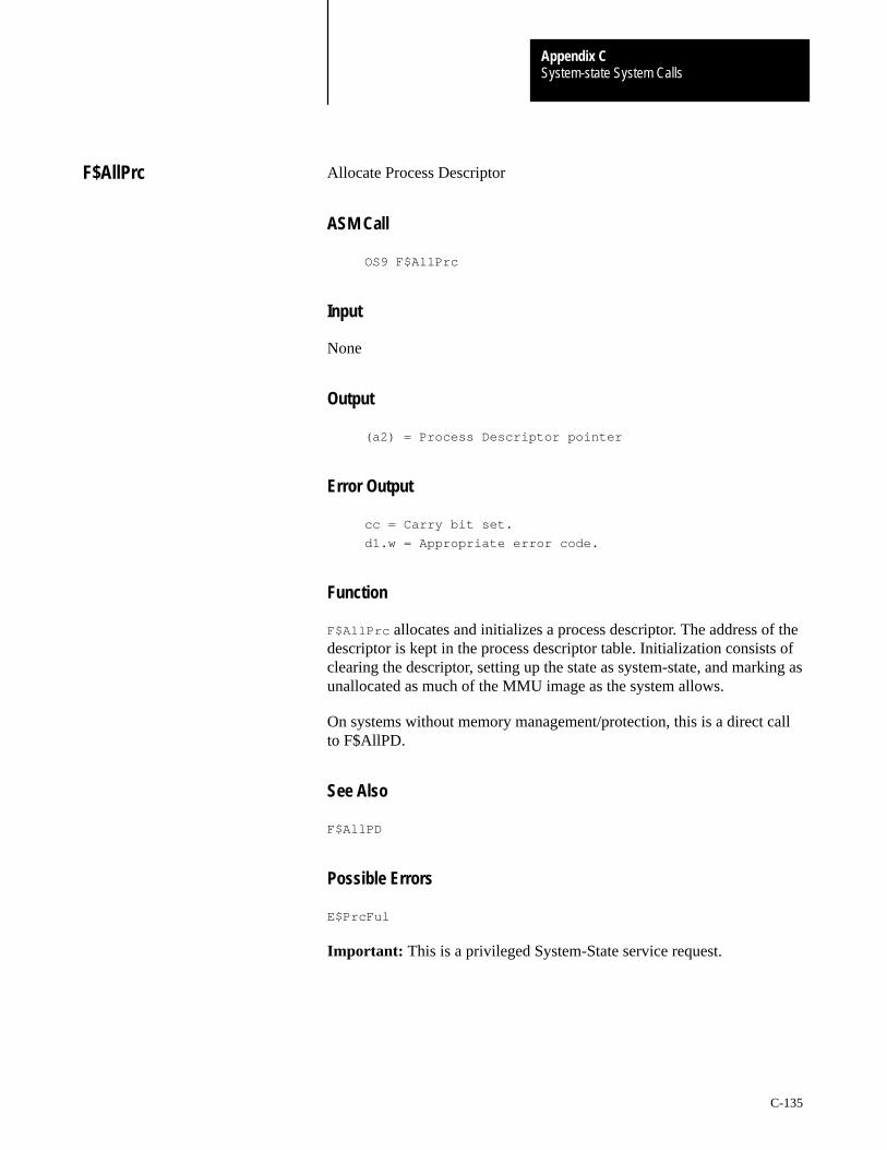
System-state System CallsAppendix C
C-135
Allocate Process Descriptor
ASM Call
OS9 F$AllPrc
Input
None
Output
(a2) = Process Descriptor pointer
Error Output
cc = Carry bit set.
d1.w = Appropriate error code.
Function
F$AllPrc allocates and initializes a process descriptor. The address of thedescriptor is kept in the process descriptor table. Initialization consists ofclearing the descriptor, setting up the state as system-state, and marking asunallocated as much of the MMU image as the system allows.
On systems without memory management/protection, this is a direct callto F$AllPD.
See Also
F$AllPD
Possible Errors
E$PrcFul
Important: This is a privileged System-State service request.
F$AllPrc
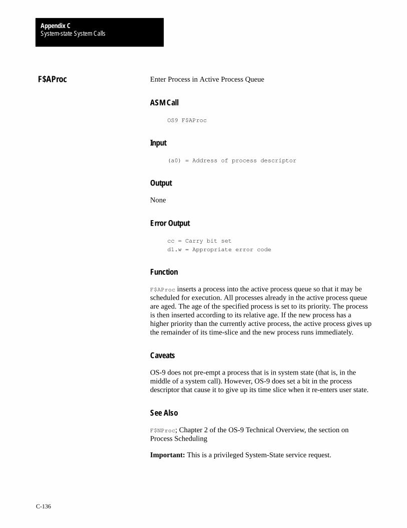
System-state System CallsAppendix C
C-136
Enter Process in Active Process Queue
ASM Call
OS9 F$AProc
Input
(a0) = Address of process descriptor
Output
None
Error Output
cc = Carry bit set
d1.w = Appropriate error code
Function
F$AProc inserts a process into the active process queue so that it may bescheduled for execution. All processes already in the active process queueare aged. The age of the specified process is set to its priority. The processis then inserted according to its relative age. If the new process has ahigher priority than the currently active process, the active process gives upthe remainder of its time-slice and the new process runs immediately.
Caveats
OS-9 does not pre-empt a process that is in system state (that is, in themiddle of a system call). However, OS-9 does set a bit in the processdescriptor that cause it to give up its time slice when it re-enters user state.
See Also
F$NProc ; Chapter 2 of the OS-9 Technical Overview, the section onProcess Scheduling
Important: This is a privileged System-State service request.
F$AProc

System-state System CallsAppendix C
C-137
De-Allocate Process Descriptor Service Request
ASM Call
OS9 F$DelPrc
Input
d0.w = process ID to de–allocate
Output
None
Error Output
cc = carry set
d1.w = appropriate error code
Function
F$DelPrc de-allocates a process descriptor previously allocated byF$AllPD. It is the caller’s responsibility to ensure that any systemresources used by the process are returned prior to calling F$DelPrc.
Currently, the F$DelPrc request is simply a convenient interface to theF$RetPD service request. It is preferred to F$RetPD to ensurecompatibility with future releases of the operating system that may need toperform process specific de-allocations.
See Also
F$AllPrc , F$AllPD , F$FindPD , and F$RetPD.
Possible Errors
E$BNam and E$KwnMod.
Important: This is a privileged System-State service request.
F$DelPrc
System-state System CallsAppendix C
C-138
Find Process/Path Descriptor
ASM Call
OS9 F$FindPD
Input
d0.w = process/path number
(a0) = process/path table pointer
Output
(a1) = pointer to process/path descriptor
Error Output
cc = Carry bit set
d1.w = error code if error
Function
F$FindPD converts a process or path number to the absolute address of itsdescriptor data structure. You can use it for simple memory management offixed length blocks. See F$AllPD for a description of the datastructure used.
See Also
F$AllPd and F$RetPd .
Important: This is a privileged System-State service request.
F$FindPD

System-state System CallsAppendix C
C-139
Enter I/O Queue
ASM Call
OS9 F$IOQu
Input
d0.w = Process Number
Output
None
Error Output
cc = Carry bit set
d1.w = Appropriate error code
Function
F$IOQu links the calling process into the I/O queue of the specified processand performs an untimed sleep. It is assumed that routines associated withthe specified process send a wakeup signal to the calling process. IOQu isused primarily and extensively by the I/O system.
For example, if a process needs to do I/O on a particular device that is busyservicing another request, the calling process performs an F$IOQu call tothe process in control of the device. When the first process returns from thefile manager, the kernel automatically wakes up the IOQu-ed process.
See Also
F$FindPd , F$Send, and F$Sleep .
Important: This is a privileged System-State service request.
F$IOQu
System-state System CallsAppendix C
C-140
Add or Remove Device From IRQ Table
ASM Call
OS9 F$IRQ
Input
d0.b = vector number
25–31 for autovectors
57–63 for 68070 on–chip autovectors
64–255 for vectored IRQs
d1.b = priority (0 = polled first, 255 = last)
(a0) = IRQ service routine entry point (0 = delete)
(a2) = device static storage
(a3) = port address
Output
None
Error Output
cc = Carry bit set
d1.w = Appropriate error code
Function
F$IRQ installs an IRQ service routine into the system polling table. If (a0)equals zero, the call deletes the IRQ service routine, and only (d0/a0/a2)are used.
The port is sorted by priority onto a list of devices for the specified vector.If the priority is zero, only this device is allowed to use the vector.Otherwise, any vector may support multiple devices. OS-9 does not pollthe I/O port prior to calling the interrupt service routine and makes no useof (a3). Device drivers are required to determine if their device caused theinterrupt. Service routines conform to the following register conventions:
Input:
(a2) = global static pointer
(a3) = port address
(a6) = system global data pointer (D_’s)
(a7) = system stack (in active proc’s descriptor)
F$IRQ
System-state System CallsAppendix C
C-141
Output:
None
Error Output:
Carry bit set if the device did not cause the
interrupt.
ATTENTION: Interrupt service routines may destroy thefollowing registers: d0, d1, a0, a2, a3, and/or a6. You mustpreserve all other registers used.
See Also
The OS-9 Technical I/O Manual contains more information on RBF andSCF device drivers.
Caveat
You may not put zero priority multiple auto-vectored devices on thepolling list.
Possible Errors
E$POLL is returned if the polling table is full.
Important: This is a privileged System-State service request.
System-state System CallsAppendix C
C-142
Move Data (Low Bound First)
ASM Call
OS9 F$Move
Input
d2.1 = Byte count to copy
(a0) = Source pointer
(a2) = Destination pointer
Output
None
Error Output
cc = Carry bit set
d1.w = Appropriate error code
Function
F$Move is a fast “block-move” subroutine capable of copying data bytesfrom one address space to another (usually from system to user orvice versa).
The data movement subroutine is optimized to make use of long moveswhenever possible. If the source and destination buffers overlap, anappropriate move (left to right or right to left) is used to avoid loss of datadue to incorrect propagation.
Important: This is a privileged System-State service request.
F$Move

System-state System CallsAppendix C
C-143
Start Next Process
ASM Call
OS9 F$NProc
Input
None
Output
Control does not return to caller.
Error Output
cc = Carry bit set
d1.w = Appropriate error code
Function
F$NProc takes the next process out of the Active Process Queue andinitiates its execution. If there is no process in the queue, OS-9 waits for aninterrupt, and then checks the active process queue again.
Caveats
The process calling NProc should already be in one of the system’s processqueues. If it is not, the calling process becomes unknown to the systemeven though the process descriptor still exists and is printed out by aprocs command.
See Also
F$AProc
Important: This is a privileged System-State service request.
F$NProc
System-state System CallsAppendix C
C-144
System Catastrophic Occurrence
ASM Call
OS9 F$Panic
Input
d0.l = panic code
Output
None. F$Panic generally does not return.
Error Output
cc = Carry bit set
d1.w = Appropriate error code
Function
The OS-9 kernel makes a F$Panic request when it detects a disastrous, butnot necessarily fatal, system condition. Ordinarily, F$Panic is undefinedand the system dies.
The system administrator may install a service routine for F$Panic as partof an OS9P2 startup module. The function of such a routine might be tofork a warmstart Sysgo process or to cause the system to re-boot.
Two panic codes are defined:
K$Idle The system has no processes to execute.K$PFail Power failure has been detected.
F$Panic is called only when the kernel believes there are no processesremaining to be executed. Although it is likely the system is dead at thispoint, it may not be. Interrupt service routines or system-state alarms couldcause the system to become active.
Important: The OS-9 kernel does not detect power failure. However,some machines are equipped with hardware capable of detecting powerfailure. For these machines, an OS9P2 routine could be installed to callF$Panic when power failure occurs.
See Also
F$SSvc; Chapter 2 of the OS-9 Technical Overview, the section oninstalling system-state routines.
F$Panic
System-state System CallsAppendix C
C-145
Return Process/Path Descriptor
ASM Call
OS9 F$RetPD
Input
d0.w = process/path number
(a0) = process/path table pointer
Output
None
Error Output
cc = Carry bit set
d1.w = Appropriate error code
Function
F$RetPD de-allocates a process or path descriptor. It can be used inconjunction with F$AllPD and F$FindPD to perform simple memorymanagement of other fixed length objects.
See Also
F$AllPD and F$FindPD .
Important: This is a privileged System-State service request.
F$RetPD
System-state System CallsAppendix C
C-146
Service Request Table Initialization
ASM Call
OS9 F$SSvc
Input
(a1) = pointer to service request initialization table
(a3) = user defined
Output
None
Error Output
cc = Carry bit set
d1.w = Appropriate error code
Function
F$SSvc adds or replaces function requests in OS-9’s user and privilegedsystem service request tables.
(a3) is intended to point to global static storage. This allows a global datapointer to be associated with each installed system call. Whenever thesystem call is invoked, the data pointer is automatically passed. Whatever(a3) points to is passed to the system call; (a3) may point to anything.
An example initialization table might look like this:
SvcTbl
dc.w F$Service OS–9 service request code
dc.w Routine–*–2 offset of routine to process request
:
dc.w F$Service+SysTrap redefine system level request
dc.w SysRoutn–*–4 offset of routine to handle system request
:
dc.w –1 end of table
Valid service request codes range from (0-255).
If the sign bit of the function code word is set, only the system table isupdated. Otherwise, both the system and user tables are updated.
F$SSvc
System-state System CallsAppendix C
C-147
You can only call privileged system service requests from routinesexecuting in System (supervisor) state. The example above shows how aservice call that must behave differently in system state than it does in userstate is installed.
System service routines are executed in supervisor state, and are notsubject to time-sliced task-switching. They are written to conform toregister conventions shown in the following table:
Input:
d0–d4 = user’s values
(a0)–(a2) = user’s values
(a4) = current process descriptor pointer
(a5) = user’s registers image pointer
(a6) = system global data pointer
Output:
cc = carry set
d1.w = error code if error
The service request routine should process its request and return fromsubroutine with a RTS instruction. Any of the registers d0-d7 and (a0)-(a6)may be destroyed by the routine, although for convenience, (a4)-(a6) aregenerally left intact.
The user’s register stack frame pointed to by (a5) is defined in the librarysys.l and follows the natural hardware stacking order. If the carry bit isreturned set, the service dispatcher sets R$cc and R$d1.w in the user’sregister stack. Any other values to be returned to the user must be changedin their stack by the service routine.
Important: This is a privileged System-State service request.
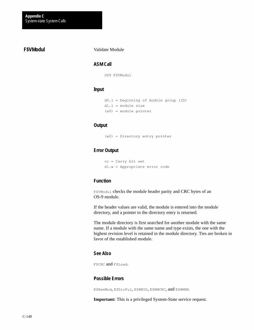
System-state System CallsAppendix C
C-148
Validate Module
ASM Call
OS9 F$VModul
Input
d0.l = beginning of module group (ID)
d1.l = module size
(a0) = module pointer
Output
(a2) = Directory entry pointer
Error Output
cc = Carry bit set
d1.w = Appropriate error code
Function
F$VModul checks the module header parity and CRC bytes of anOS-9 module.
If the header values are valid, the module is entered into the moduledirectory, and a pointer to the directory entry is returned.
The module directory is first searched for another module with the samename. If a module with the same name and type exists, the one with thehighest revision level is retained in the module directory. Ties are broken infavor of the established module.
See Also
F$CRC and F$Load .
Possible Errors
E$KwnMod, E$DirFul , E$BMID, E$BMCRC, and E$BMHP.
Important: This is a privileged System-State service request.
F$VModul

With offices in major cities worldwide
WORLDHEADQUARTERSAllen-Bradley1201 South Second StreetMilwaukee, WI 53204 USATel: (414) 382-2000Telex: 43 11 016FAX: (414) 382-4444
EUROPE/MIDDLEEAST/AFRICAHEADQUARTERSAllen-Bradley Europa B.V.Amsterdamseweg 151422 AC UithoornThe NetherlandsTel: (31) 2975/60611Telex: (844) 18042FAX: (31) 2975/60222
ASIA/PACIFICHEADQUARTERSAllen-Bradley (Hong Kong)LimitedRoom 1006, Block B, SeaView Estate28 Watson RoadHong KongTel: (852) 887-4788Telex: (780) 64347FAX: (852) 510-9436
CANADAHEADQUARTERSAllen-Bradley CanadaLimited135 Dundas StreetCambridge, Ontario N1R5X1CanadaTel: (519) 623-1810FAX: (519) 623-8930
LATIN AMERICAHEADQUARTERSAllen-Bradley1201 South Second StreetMilwaukee, WI 53204 USATel: (414) 382-2000Telex: 43 11 016FAX: (414) 382-2400
As a subsidiary of Rockwell International, one of the world’s largest technologycompanies — Allen-Bradley meets today’s challenges of industrial automation with over85 years of practical plant-floor experience. More than 13,000 employees throughout theworld design, manufacture and apply a wide range of control and automation productsand supporting services to help our customers continuously improve quality, productivityand time to market. These products and services not only control individual machines butintegrate the manufacturing process, while providing access to vital plant floor data thatcan be used to support decision-making throughout the enterprise.
Publication 1771-6.5.107 January 1993 PN 955113-20Printed in USA