Embed Size (px)
Citation preview

www.plymovent.com
EN User manual
OS-3 AUTOMATIC SYSTEM CONTROL
EN Control Box

00000116183/300421/D OS-3 1
TABLE OF CONTENTS
TABLE OF CONTENTS ......................................................................................................1
General Precautions ........................................................................................................2
Preface .........................................................................................................................4
1 Introduction ..................................................................................................................4
1.1 IdentificationofTheProduct ............................................................................................41.2 General Description ........................................................................................................41.3 Product Combinations .....................................................................................................41.4 TechnicalSpecifications ...................................................................................................41.5 Ambient Conditions ........................................................................................................41.6 TransportofTheUnit ......................................................................................................4
2 Product Description ........................................................................................................5
2.1 Operation ......................................................................................................................5
3 Safety...........................................................................................................................5
4 Installation ....................................................................................................................6
4.1 Unpacking .....................................................................................................................64.2 Electric Connection .........................................................................................................64.3 PrimaryWiringProcedure ................................................................................................64.4 PrimaryWiringProcedures(ControlWiring) .......................................................................74.5 TransformerWiringProcedure ..........................................................................................74.6 PressureSwitchProcedure ...............................................................................................84.7 TemperatureSwitchProcedure .........................................................................................84.8 Wireless Control System Procedure ...................................................................................8
5 Maintenance ..................................................................................................................9
6 Troubleshooting .............................................................................................................9
7 Spare Parts ...................................................................................................................9
8 Electricaldiagram ...........................................................................................................9
9 Disposal ........................................................................................................................9

00000116183/300421/D OS-3 2
GENERAL PRECAUTIONS
ATTENTIONAllowonlyqualifiedpersonnelfamiliarwithadjustablefrequencyACdrives,andassociatedmachinerytoplanorimplementtheinstallation,start-upandsubsequentmaintenanceofthesystem.Failuretocomplycanresultinpersonalinjuryand/orequipmentdamage.
ATTENTIONToavoidanelectricshockhazard,verifythatthevoltageonthebuscapacitorshasdischargedbeforeperforminganyworkontheelectricalcontrols,switchesand/ordrivesifapplicable.
ATTENTIONIncorrectly applied or installed electrical controls, switchesand/ordrivescanresultincomponentdamageorareductioninproductlife.Wiringorapplicationerrors,suchas,undersizingthemotor,incorrect or inadequate AC supply, or excessive ambienttemperaturescanresultinmalfunctionofthesystem.
ATTENTIONTheelectricalcontrols,switchesand/ordrivesmaycontainESD(ElectrostaticDischarge)sensitivepartsand assemblies. Static control precautions may be requiredwheninstalling,testing,servicingorrepairingthisassembly.Componentdamagecanresult if ESD control procedures are not followed.
IMPORTANT USER INFORMATIONReadthisdocumentinentiretybeforeyouinstall,configure,operate,ormaintainthisproduct.Usersarerequiredtofamiliarizethemselveswithinstallationandwiringinstructionsinaddition to requirements of all applicable codes, laws and standards.
Activitiesincludinginstallation,adjustments,puttingintoservice,use, assembly, disassembly, and maintenance are required to be carriedoutbysuitablytrainedpersonnelinaccordancewithapplicable code of practice.
Ifthisequipmentisusedinamannernotspecifiedbythemanufacturer,theprotectionprovidedbytheequipmentmaybeimpaired.
In no event will Plymovent be responsible or liable for indirect or consequentialdamagesresultingfromtheuseorapplicationofthisequipment.
Theexamplesanddiagramsinthismanualareincludedsolelyforillustrativepurposes.Becauseofthemanyvariablesandrequirementsassociatedwithanyparticulateinstallation,Plymovent cannot assume responsibility or liability for actual use basedontheexamplesanddiagrams.
NopatentliabilityisassumedbyPlymoventwithrespecttouseofinformation,circuits,equipment,orsoftwarethatmaybedescribedinthismanual.Throughoutthismanual,whennecessary,notesmaybeusedtomakeyouawareofsafetyconsiderations.
Theoperationofexhaustextractionsystemscanbeaffectedbyvariousfactorsincludingbutnotlimitedtoproperdesignofthe
system,operatingprocedures,serviceandmaintenance.Fumeexhaustexposurelevelsshouldbecheckeduponinstallationandperiodicallythereaftertoensurethattheyfallwithinapplicableregulationsandexposurelimitvalues.
Plymoventsystemsaremadecodecompliant,pleaseensurethesystemisproperlydesigned,operated,servicedandmaintained.
WARNING!Identifiesinformationaboutpracticesorcircumstancesthatcancauseanexplosioninahazardousenvironment,whichmayleadtopersonalinjury,death,propertydamage,oreconomicloss.
ATTENTIONIdentifiesinformationaboutpracticesorcircumstancesthatcanleadtopersonalinjuryordeath,propertydamage,oreconomicloss.Attentionshelpyouidentifyahazard,avoidahazard,andrecognizetheconsequent.
IMPORTANTIdentifiesinformationthatiscriticalforsuccessfulapplicationandunderstandingoftheproduct.
SHOCK HAZARDLabelsmaybeonoutsideorinsideoftheequipment,forexamplecontrolbox,toalertpeoplethatdangerousvoltagemaybepresent.
ARC FLASH HAZARDLabelsmaybeonoutsideorinsideoftheequipment,for example control box, to alert people to potential ArcFlash.ArcFlashwillcausesevereinjuryordeath.WearproperPersonalProtectionEquipment(PPE).FollowALLregulatoryrequirementsforsafeworkpracticesandforPersonalProtectiveEquipment(PPE).
BE SURE THAT ALL INSTALLATION, OPERATION, MAINTENANCE AND REPAIR PROCEDURES ARE PERFORMED ONLY BY QUALIFIED INDIVIDUALS.

00000116183/300421/D OS-3 3
EN - ORIGINAL INSTRUCTIONAllrightsreserved.Theinformationgiveninthisdocumenthasbeencollectedforthegeneralconvenienceofourclients.Ithasbeenbasedongeneraldatapertainingtoconstructionmaterialpropertiesandworkingmethodsknowntousatthetimeofissueofthedocumentandisthereforesubjectatanytimetochangeoramendment,andtherighttochangeoramendisherebyexpresslyreserved.Changesmaybemadewithorwithoutnotification,itistheusersresponsibilitytoensuretheyhaveattainedthemostrecentcopyofthisdocumentfortheirfiles.Theinstructionsinthispublicationonlyserveasaguidelineforinstallation,use,maintenanceandrepairoftheproductmentionedonthecoverpageofthisdocument.Thispublicationistobeusedforthestandardmodeloftheproductofthetypegivenonthecoverpage.Thusthemanufacturercannotbeheldresponsibleforanydamageresultingfromtheapplicationofthispublicationtotheversionactuallydeliveredtoyou.Thispublicationhasbeenwrittenwithgreatcare.However,themanufacturercannotbeheldresponsible,eitherforanyerrorsoccurringinthispublicationorfortheirconsequences.

00000116183/300421/D OS-3 4
PREFACE
Using this manualThismanualisintendedtobeusedasaworkofreferenceforprofessional,welltrainedandauthorizeduserstobeabletosafelyinstall,use,maintainandrepairtheproductmentionedonthecoverofthisdocument.Thisusermanualshouldalwaysbekeptwiththeproduct,aswellasaduplicatecopybekeptbythefiredepartmentorcityservicedepartmentafterinstallation.
Pictograms and symbolsThefollowingpictogramsandsymbolsareusedinthismanual:
ATTENTIONAremarkwithadditionalinformationfortheuser.Aremarkbringspossibleproblemstotheuser’sattention.CAUTION!Procedures,ifnotcarriedoutwiththenecessarycaution,coulddamagetheproduct,theworkshoportheenvironment.WARNING!Procedureswhich,ifnotcarriedoutwiththenecessarycaution,maydamagetheproductand/orcauseseriouspersonalinjury.CAUTION!Riskofelectricshock.
WARNING!Firehazard!Importantwarningtopreventfire.
Text IndicatorsListingsindicatedby“-”(hyphen)concernenumerations.Listingsindicatedby“•”(bulletpoint)describestepstoperform.
Service and Technical SupportForinformationaboutspecificadjustments,maintenanceorrepairjobswhicharenotdealtwithinthismanual,pleasecontactthesupplieroftheproduct.Theywillalwaysbewillingtohelpyou.Makesureyouhavethefollowingspecificationsathand: - product name - serial number
Youcanfindthisdataontheidentificationplate.
1 INTRODUCTION
1.1 Identification of The Product
Theidentificationplatecontains,amongotherthings,thefollowingdata: - product name - serial number - supplyvoltageandfrequency - power consumption
1.2 General Description
TheOS-3controlboxisanenergysavingcontrolunitdesignedtobeusedforcontrollingexhaustfansinvehicleexhaustsystems,withorwithoutaparticlefiltrationsystem.Togetherwithapressureswitchandoptionaltemperatureswitch,thisenergysavingcontrollermakesafullyautomaticsystemforthe
controlofthevehicleexhaustfan.Thecontrollercanbesetforbothmanualorautomaticcontrolofthefan.Dependingontheconfigurationofasystem,severaloptionsforswitchesandremotestartfunctionsareavailable.Thetwomostcommontypesofswitchesthataretypicallyusedareapressureswitchtodetectpressuredifferencesinthesystemwhenavehicleisconnected,and,anoptionaltemperatureswitchtodetecttemperaturelevelsinthesystemalsocreatedwhenavehicleisconnected.
TheOS-3alsoincludesanalarmoutput,whichcanbeusedforstatusoutputtoanonsitecontrolsystem(byothers).Abuilt-indelayofffunctionwillensurethatthefancontinuestorunforsometimeafterthevehiclehasbeendisconnected,thisensuresallofthetoxicgasesintheductsystemwillbeexhaustedoutoftheductingbeforethefanstops.Thedelayofftimecaneasilybeadjustedbetween3minutes-60minutes.
1.3 Product Combinations
TheOS-3controlboxisdesignedinconjunctionwithPlymoventvehicleexhaustextractionsystemcomponentsincludingPlymoventfansandSTR,VSRandSBTrailsystemsspecificallyforemergencyresponseandfirevehicleapplications.
1.4 Technical Specifications
LxWxH 15.75”x6”x11.75”(400mmx152mmx298mm)
MountingHoleDiameter .4”(10mm)diameterholes
MountingHoleLocation 14.15”x10.15”(359mmx258mm)oncenters
Weight 25lbs(11.34kg)
BoxRating NEMA 12
CompliantWith CE,NFPA,cUL*
DelayOffTimerRange 3minutes-60minutes
*Formostup-to-dateULinformation,includingonPlymovent,pleasevisittheonlinecertificationsdirectoryatwww.ul.com.
Refertotheavailableproductdatasheetfordetailedproductspecifications.
1.5 Ambient Conditions
Operatingtemperature: - min. - nom. - max.
- 41°F(5°C) - 68°F(20°C) - 104°F(40°C)
Max.relativehumidity 80%Storageconditions - 41-104°F(5-40°C)
- relativehumiditymax.80%Suitable for outdoor use no
1.6 Transport of The Unit
TheOS-3controlboxisdeliveredasself-containedexhaustsystemcontrollercompletewithfunctionsformanualrun,andautomaticstartwithdelayoffandstop.
Themanufacturercannotbeheldliableforanydamagetotheunitduetoshippingormishandling.Alwayshandletheunitandtheaccompanyingoptionsand/oraccessories,ifany,withcare.

00000116183/300421/D OS-3 5
2 PRODUCT DESCRIPTION
2.1 Operation
Thecontrollercanbesetforbothmanualorautomaticcontrolofthefan.Dependingonsystem,differentswitchesforstartingthesystemcanbeused.Mainlytwotypesofswitcheswillbeused;pressureswitchtodetectpressuredifferenceinsystemsandtemperatureswitchestodetecttemperaturelevelinthesystem.
TheOS-3controlboxalsoincludesavisiblealarmdevice,whichcanbeusedforstatusoftheairflowintheexhaustsystem.Abuiltin“afterrunningtime”functionwillsecurethattoxicgasesintheductsystemwillbeexhaustedoutoftheductingbeforethefanstops.Theafterrunningtimecaneasilybeadjustedbetween3minutes-60minutes.
Whenthecontrolunitissetinto“automatic”position,theexhaustfanisstartedbyasignalfromanexternallymountedpressure,or/andtemperatureswitch.Normallythesystemisactivatedbythepressureswitchandkeptrunningbytheoptionaltemperatureswitch.
2.1.1 Pressure switch
Thepressureswitchreactstoanincreaseinpressurewithinthehose(positivepressure)whichoccursinthesystemwhenavehicleisstarteduporattachedwhileitisrunning.Thepressureswitchisadjustabletoaccomodatevariousenginesizes.Adjustmentstothisswitchshouldonlybeperformedbyauthorizedservicetechnician.
2.1.2 Optional: Temperature switch
Theoptionaltemperatureswitchdetectswhenthetemperatureinthesystemhasreachedbetween90°Fto130°F(32°Cto54°C)(tobedeterminedandadjustedbyanauthorizedservicetechnicianonly).
Thistemperatureriseoccurswhenarunningvehicleisattachedtothesystem,andwillensurethesystemstaysrunningwhilethevehicleisinoperation.
2.1.3 Automatic Mode
Thismodeofoperationallowsforeverydayusewhenexitingthefirestationforemergencycalls.Whentheengineisstarted,thepressureswitchcloses,thiscompletesthecircuittothecontrolboxcausingthefantoturnon.Whentheengineturnsoffortheapparatusleavesthefirestation,thepressureand/ortemperatureinthesystemdecreasesandthecontrolboxenteresintoadelayoffmode.Oncethetimerhascompletedits(adjustable)timedelay,thefanstopsafterthepresetruntimeisup.
2.1.4 Manual Mode
WhenthecontrolboxissettotheManualRunMode,theexhaustfanwillruncontinuously.Thisshouldbeutilizedforstationaryrunningofthevehiclesinthefirestationformaintenancechecks.WhileintheManualRunModeandrunningavehicleatHIGHIDLE,operationshouldbelimitedto1500RPMfor5minutes.ToexitManualRunMode,presstheSTOPbutton.ThesystemwillshutdownandautomaticallyreturntoAUTOSTARTandbereadyforthenextemergencycall.For2007ornewerdieselvehicleswithDPF(DieselParticulateFilter)unitsshouldneverbeallowedto“regenerate”whileconnectedtotheexhaustsystem.Vehicleswhichhaverecentlyundergone“regeneration”shouldnotbeconnectedtothesystemuntilnormalexhaustgasoperatingtemperatureshavereturned.
2.1.5 Stop Mode
Whenpressingthestopbutton,thefanwillstopimmediately,andafterashortperiodoftime(2-3seconds),thecontrolboxwillautomaticallymovebackintoautomaticmode.Thisisabuilt-insafetyfunctionwhichwillreducetheriskofhavingexhaustgasleakageinthesystemduetooperatorerror.
2.1.6 Alarm Mode
Thealarmdevicewilldetecthighpressurelossacrosstheoptionalfilterunit.WhentheFanOnLEDindicatorlightisflashing,thepressureacrossthefilterhasexceededtheacceptablerange,thefiltershouldbereplacedassoonaspossible to maintain proper system operation.
3 SAFETY
GeneralThemanufacturerdoesnotacceptanyliabilityfordamagetotheproductorpersonalinjurycausedbyignoringthesafetyinstructionsinthismanual,orbynegligenceduringinstallation,use,maintenance,andrepairoftheproductmentionedonthecoverofthisdocumentandanycorrespondingaccessories.Specificworkingconditionsorusedaccessoriesmayrequireadditional safety instructions. Immediately contact your supplier ifyoudetectapotentialdangerwhenusingtheproduct.
The user of the product is always fully responsible for observing the local safety instructions and regulations.
User Manual - Everyoneworkingonorwiththeproductmustbefamiliarwiththecontentsofthismanualandmuststrictlyobservetheinstructionstherein.Themanagementshouldinstructthepersonnelinaccordancewiththemanualandobserveallinstructionsanddirectionsgiven.
- Neverchangetheorderofthestepstoperform. - Thisusermanualshouldalwaysbekeptwiththeproduct,aswellasaduplicatecopybekeptbythefiredepartmentorcityservice department after installation.
- Theexamplesanddiagramsinthismanualareincludedsolelyforillustrativepurposes.Becauseofthemanyvariablesandrequirementsassociatedwithanyparticularinstallation,Plymovent cannot assume responsibility or liability for actual usebasedontheexamplesanddiagrams.
- NopatentliabilityisassumedbyPlymoventwithrespecttouseofinformation,circuits,orequipmentdescribedinthismanual.
- Reproductionofthecontentsofthismanual,inwholeorinpart,withoutpriorwrittenpermissionofPlymoventisprohibited.
Pictograms and Instructions On The Product (if present) - Thepictograms,warningandinstructionsattachedtotheproductarepartofthesafetyfeatures.Theymustnotbecoveredorremovedandmustbepresentandlegibleduringtheentirelifeoftheproduct.
- Ifpictogram,instructionsorlabelsontheproductbecomedamaged,missingorillegibleimmediatelydiscontinueuseoftheunitandreplaceorrepairdamagedorillegiblepictogram,warningsandinstructions.
- Contactyourlocalauthorizedservicetechnicianforsupport.
UsersTheuseofthisproductisexclusivelyreservedtoauthorized,trainedandqualifiedusers.Temporarypersonnelandpersonnel

00000116183/300421/D OS-3 6
intrainingcanonlyusetheproductundersupervisionandresponsibilityofskilledtechnicians.
Intended Use1
TheproducthasbeendesignedasacontrolboxtooperateaPlymoventexhaustextractionfan.Usingtheproductforotherpurposesisconsideredcontrarytoitsintendeduse.Themanufactureracceptsnoliabilityforanydamagesorinjuryresultingfromsuchuse.Theproducthasbeenbuiltinaccordancewithstate-of-the-artstandardsandrecognizedsafetyregulations.Onlyusethisproductwheninaccordancewithitsintendeduseandtheinstructionsexplainedintheusermanual.
Technical SpecificationsThespecificationsgiveninthismanualmustnotbealteredfromtheinformationgivenherewithin.Thisinformationissubjecttochangeatanytimewithorwithoutnotice.
ModificationsModificationof(partsof)theproductisnotallowed,exceptthebottomplate,whichisallowedtobeusedasentrancepointforexternalcabling.
Installation - Theinstallationofthisproductisexclusivelyreservedtoauthorized,well-trainedandqualifiedelectrician.
- All installations must meet any and all applicable local laws, regulations,standardsandrequirements.
- Itistheresponsibilityoftheinstallingpartytoensurethatallcodesaremetduringtheinstallationofthiscontrolsystem.Anyinspectionsrequiredarethesoleresponsibilityoftheinstallingparty.
- Inspecttheproductandcheckitfordamage. - Verifythefunctioningofthesafetyfeatures. - Neverinstalltheproductinfrontofentrancesandexitswhichmustbeusedforemergencyservices.
- Makesurethattheworkshop,inthevicinityoftheproduct,containssufficientapprovedfireextinguishers.
- Itisrecommendedthatthecontrolboxbemountedatapproximately6feet(1.8m)abovefinishedfloorleveltofacilitate operator use and service if necessary.
Use - Checktheworkingenvironment.Donotallowunauthorizedpersonstoentertheworkingenvironment.
- Protecttheproductagainstwaterandhumidity. - Stayalertandkeepyourattentiontoyourwork.Donotusetheproductwhenyouareundertheinfluenceofdrugs,alcoholor medicine.
- Makesuretheroomisalwayssufficientlyventilated; thisappliesespeciallytoconfinedspaces.
Service, maintenance and repairs
WARNING!Maintenanceshouldonlybeperformedbyauthorized,qualifiedandtrainedpersons(skilled)usingappropriateworkpractices.WARNING!Electrocution hazardDisconnectmainsbeforeservicing.Failuretodosocouldresultinseriouspersonalinjuryordeath.
1 “Intendeduse”asexplainedinEN-ISO12100istheuseforwhichthetechnicalproductissuitedasspecifiedbythemanufacturer,inclusiveofmanufacturersdirectionsinthesalesbrochure.Incaseofdoubt,itistheusewhichcanbededucedfromtheconstruction,themodelandthefunctionofthetechnicalproductwhichisconsiderednormaluse.Operatingthemachinewithinthelimitsofitsintendedusealsoinvolvesobservingtheinstructionsintheusermanual.
4 INSTALLATION
WARNING!Donotattemptinstallationofthisunitunlessyouarefamiliarwiththenecessarytools,equipment,utilityconnectionsandpotentialhazards.Installationshouldbeperformedonlybyaqualifiedservice provider. Failure to do so could result in reducedperformanceoftheunit,seriouspersonalinjuryordeath.WARNING!Fire hazardNeverinstallthecontrolboxinareaswithflammablegases.ATTENTIONTheOS-3 controlboxisdeliveredwithoutcablesforexternalfieldwiring.Allinterconnectcables/wiresizeusedshallbesuppliedbyothersandcomplywithUL,NECandallothernationalandlocalstandardscodes.TheglandsusedforinsertingthecableintotheOS-3 controlboxshouldbeplacedinthebottomofthecasing.ThecableshouldfittightlyintheglandtopreventanymoistureenteringtheinsideoftheOS-3 control box.
4.1 Unpacking
Checkthattheproductiscomplete.Thepackageshouldcontain: - OS-3 control box - doorkey
4.2 Electric connection
ConnecttheOS-3inaccordancewiththeseparatelysuppliedelectricaldiagram.
CAUTION!Electric connection to be executed in accordance withlocalrequirements.EnsurecompliancewiththeEMCregulatoryarrangements.WARNING!Makesurethemachineissuitableforconnectiontothelocalmains.Informationabouttheconnectionvoltageandfrequencycanbefoundontheidentificationplate.ATTENTIONThethermalrelayshouldbesetaccordingtotheoverloadmentionedontheidentificationplateonthemotor.
4.3 Primary Wiring Procedure
4.3.1 Terminal Block 1
Islocatedinthelowerleft-handcorneroftheOS-3controlboxandconsistsofincomingpowerelectricalterminalblocksL1,L2,L3.Itisimportanttonoteonsinglephaseboxes,L3willnotbeinstalled.OutgoingpowertothefanmotorviatheoverloadoutputlocationsT1,T2,T3onsinglephasecontrolboxestheT3terminalwillbeoccupiedbyawirelooping“backthrough”thecontactor,thisisnecessaryforproperoperationandshouldnotbealtered.Groundshouldbelandedonterminalstriponthegreenandyellowterminalblock,lowvoltagecontrolwiring

00000116183/300421/D OS-3 7
terminalblocks(0,24Vand1through8)andelectricaloverloadusesforprotectionforbothprimary(F1,F2)andsecondary(F3).
NOTE: Primarylinevoltagemustnotbegreaterorlessthan8%ofratedvoltagelistedonvoltagetap.Forexample,Tap120volt(110–130voltagerangeisacceptable)forexcessivelylowlinevoltage,abuckboosttransformermayberequired.(Suppliedbyothers).
4.3.2 Primary Voltage Wiring
OntherightsideoftheterminalblockisthefirstterminalblockmarkedGND(greenground),hereyouwillconnectyourgroundwire(properlysizedperNEC).InthesecondterminalblockmarkedL1,youwillconnectyourfirstpowerwire.InthethirdterminalblockmarkedL2,youwillconnectyoursecondpowerwire.Forthefourthterminalblock(whenapplicable),markedL3,youwillconnectyourthirdpowerwire.
NOTE: Thelinesupplyvoltagefromyourbuilding,whichwillsupplyyourmotor,shallbeconnecteddirectlytoL1,L2forsinglephaseandL1,L2,andL3for3-phase.Re-checkthatratedvoltagecorrespondswithsupplyvoltagetoavoiddamagetoelectricalcomponentsorcontrolwiring.
Table2Aonpage13andTable2Bonpage14showthefancomponentsizingcharts.
Pleaserefertolocalcodesandrequirements,thesewilltakeprecedenceoverthesupplierwiringchartatthebackofthismanual.
4.3.3 Field Power Wiring of Control Box, Safety Disconnect and Fan Motor
TheprimarywiringoftheelectricalsystemmustberatedforthemaximumampsandHPratingofthefanmotorloadaswellasthewiringvoltagedrop,whichiscalculatedforthedistance,youarerunning.SeePlymoventWiringChartinthebackofthismanualasaguideforwiring.ItiscriticaltoalwaysfollowlocalcoderequirementsforselectingwireininstanceswheretheydifferfromPlymoventpublishedrecommendations.
NOTE: Fieldwiring,powersupplypanelandelectricalsafetydisconnectareprovidedbyothers.Plymoventassumesnoliability for any electrical installation and all national and local codesandstandardsshouldbefollowed.
4.4 Primary Wiring Procedures (Control Wiring)
4.4.1 Control Voltage Wiring
Theterminalblocks0,24Vand1through8areusedforlowvoltagecontrolwiringofoptionalwirelesscontrolsystem,remotemountedpressureswitchforstartingfunctions,cleanfilterindicatorandtemperatureswitch.AnoptionalremotealarmrelayconnectionisavailableforconnectiontoBuildingAutomationSystems(BAS).
4.4.2 Pressure Switch / Temperature Switch (engine start/stop)
Thepressureswitchandoptionaltemperatureswitch,whichissoldseparately,willbewiredtoterminalblock1and2.Ifmorethanonepressure/temperatureswitchisutilizedinasystemtheymustbewiredinparalleltoachieveproperoperation.
NOTE: Controlwiressupplyingterminalblock1and2mustbeaminimumof16AWG/1.29mm²,smallerwiresizingwillresultinimproper system operation.
Amomentarymanualpushbuttonstartswitchcanalsobeplacedinparallelinthiscircuitforremotestartingofthesystem.
4.4.3 Remote Alarm (optional)
Terminals 3, 4, and 5 are a relay dry contact connection for a BuildingAutomationSystem(BAS).Terminalblock3providesthecommonconnection,terminal4providesanormallyclosedcontact connection and terminal 5 provides a normally open contact connection.
NOTE: Relay output is a dry contact potential free and will requireadditionalcontrolequipmentdependingonitsuse.
4.4.4 Pressure Switch (filter alarm)
Anexhaustventilationparticulatefilter(suchasthePlymoventMultiSmokeFilter)maybeprovidedwithanadjustablepressureindicatorswitch,whichmonitorsthefiltersusefullife.Terminals6and7(potentialfree)areutilizedtoconnectandoperatethepressureindicatorswitch.Whenthefilterbecomesdirty,thepressureswitchwillsendasignaltothecontrolboxandin-turnwillflashtheFanOnLEDindicatorlight,locatedonthefaceoftheOS-3controlpanel,whenthefanmotorisrunning.Indicatingafilterchangeisrequired.
4.5 Transformer Wiring Procedure
4.5.1 Multi-tap Control Transformer
DesignedbyPlymoventtoallowthefieldelectriciantheabilitytoselecttheprimaryvoltageofhischoice.Thisvoltageselectionrangesfrom120voltthrough600voltVAC.Thetransformerhasbeendesignedtooperateinboth50and60Hzenvironments.
NOTE: Primarylinevoltagemustnotbegreaterorlessthan8%ofratedvoltagelistedonvoltagetap.Forexample,Tap120volt(110–130voltagevariantacceptable)forlowlinevoltage,abuckboosttransformermayberequired.(Suppliedbyothers).
4.5.2 Primary Voltage Connection
Onthetoprightsideoftransformeryouwillfindaterminalblockwith8pointsofconnection.Commonblackwireisconnectedtothetopterminalblock(blacktoyellowwire)andwillalwaysremaininthispositionregardlessofthevoltageadjustmentthatyouwillbemaking.Thevoltageadjustinggraywireispresetforthevoltageordered.Youmayberequiredtorepositionthevoltageadjustingwiretothelinesupplyvoltagepresentatyourinstallation/facility.Forexample,adjustingto120voltlinevoltage,movethevoltageadjustingwiretowiretapsecondfromthetopofterminalblock(blacktowhite).Viewyellowlabelforcorrectwiretapcolorforeachavailablevoltage.
NOTE: Improperwiringwillresultindamageofotherelectricalcomponents.Re-checkthatratedvoltagecorrespondswithsupplyvoltagetoavoiddamagetoelectricalcomponents.
Always ensure power is off and all required procedures for facility(suchaslockouttagout)areproperlyfollowedbeforemakinganyadjustmentstothecontrolsystem.
WARNING!Procedureswhich,ifnotcarriedoutwiththenecessarycaution,maydamagetheproductand/orcauseseriouspersonalinjury.
00000116183/300421/D OS-3 8
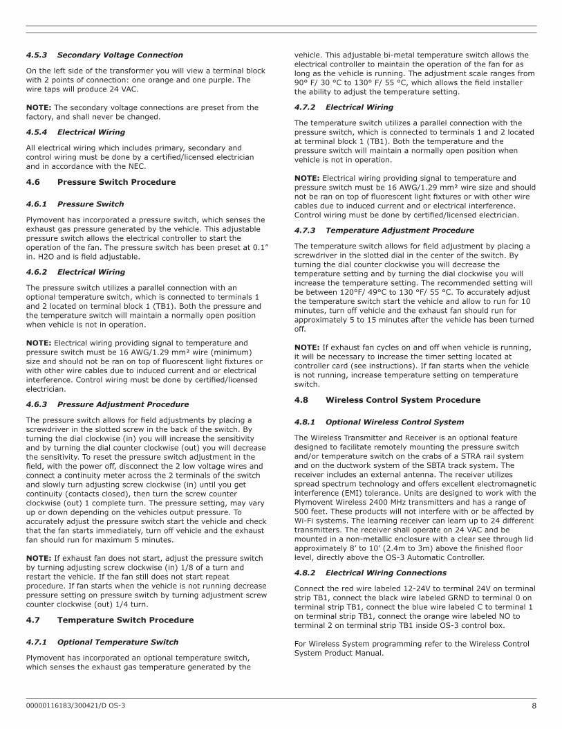
4.5.3 Secondary Voltage Connection
Ontheleftsideofthetransformeryouwillviewaterminalblockwith2pointsofconnection:oneorangeandonepurple.Thewire taps will produce 24 VAC.
NOTE: Thesecondaryvoltageconnectionsarepresetfromthefactory,andshallneverbechanged.
4.5.4 Electrical Wiring
Allelectricalwiringwhichincludesprimary,secondaryandcontrolwiringmustbedonebyacertified/licensedelectricianandinaccordancewiththeNEC.
4.6 Pressure Switch Procedure
4.6.1 Pressure Switch
Plymoventhasincorporatedapressureswitch,whichsensestheexhaustgaspressuregeneratedbythevehicle.Thisadjustablepressureswitchallowstheelectricalcontrollertostarttheoperationofthefan.Thepressureswitchhasbeenpresetat0.1”in.H2Oandisfieldadjustable.
4.6.2 Electrical Wiring
Thepressureswitchutilizesaparallelconnectionwithanoptionaltemperatureswitch,whichisconnectedtoterminals1and2locatedonterminalblock1(TB1).Boththepressureandthetemperatureswitchwillmaintainanormallyopenpositionwhenvehicleisnotinoperation.
NOTE: Electricalwiringprovidingsignaltotemperatureandpressureswitchmustbe16AWG/1.29mm²wire(minimum)sizeandshouldnotberanontopoffluorescentlightfixturesorwithotherwirecablesduetoinducedcurrentandorelectricalinterference.Controlwiringmustbedonebycertified/licensedelectrician.
4.6.3 Pressure Adjustment Procedure
Thepressureswitchallowsforfieldadjustmentsbyplacingascrewdriverintheslottedscrewinthebackoftheswitch.Byturningthedialclockwise(in)youwillincreasethesensitivityandbyturningthedialcounterclockwise(out)youwilldecreasethesensitivity.Toresetthepressureswitchadjustmentinthefield,withthepoweroff,disconnectthe2lowvoltagewiresandconnectacontinuitymeteracrossthe2terminalsoftheswitchandslowlyturnadjustingscrewclockwise(in)untilyougetcontinuity(contactsclosed),thenturnthescrewcounterclockwise(out)1completeturn.Thepressuresetting,mayvaryupordowndependingonthevehiclesoutputpressure.Toaccuratelyadjustthepressureswitchstartthevehicleandcheckthatthefanstartsimmediately,turnoffvehicleandtheexhaustfanshouldrunformaximum5minutes.
NOTE: Ifexhaustfandoesnotstart,adjustthepressureswitchbyturningadjustingscrewclockwise(in)1/8ofaturnandrestartthevehicle.Ifthefanstilldoesnotstartrepeatprocedure.Iffanstartswhenthevehicleisnotrunningdecreasepressuresettingonpressureswitchbyturningadjustmentscrewcounterclockwise(out)1/4turn.
4.7 Temperature Switch Procedure
4.7.1 Optional Temperature Switch
Plymoventhasincorporatedanoptionaltemperatureswitch,whichsensestheexhaustgastemperaturegeneratedbythe
vehicle.Thisadjustablebi-metaltemperatureswitchallowstheelectricalcontrollertomaintaintheoperationofthefanforaslongasthevehicleisrunning.Theadjustmentscalerangesfrom90°F/30°Cto130°F/55°C,whichallowsthefieldinstallertheabilitytoadjustthetemperaturesetting.
4.7.2 Electrical Wiring
Thetemperatureswitchutilizesaparallelconnectionwiththepressureswitch,whichisconnectedtoterminals1and2locatedatterminalblock1(TB1).Boththetemperatureandthepressureswitchwillmaintainanormallyopenpositionwhenvehicleisnotinoperation.
NOTE: Electricalwiringprovidingsignaltotemperatureandpressureswitchmustbe16AWG/1.29mm²wiresizeandshouldnotberanontopoffluorescentlightfixturesorwithotherwirecables due to induced current and or electrical interference. Controlwiringmustbedonebycertified/licensedelectrician.
4.7.3 Temperature Adjustment Procedure
Thetemperatureswitchallowsforfieldadjustmentbyplacingascrewdriverintheslotteddialinthecenteroftheswitch.Byturningthedialcounterclockwiseyouwilldecreasethetemperaturesettingandbyturningthedialclockwiseyouwillincreasethetemperaturesetting.Therecommendedsettingwillbebetween120°F/49°Cto130°F/55°C.Toaccuratelyadjustthetemperatureswitchstartthevehicleandallowtorunfor10minutes,turnoffvehicleandtheexhaustfanshouldrunforapproximately5to15minutesafterthevehiclehasbeenturnedoff.
NOTE:Ifexhaustfancyclesonandoffwhenvehicleisrunning,itwillbenecessarytoincreasethetimersettinglocatedatcontrollercard(seeinstructions).Iffanstartswhenthevehicleisnotrunning,increasetemperaturesettingontemperatureswitch.
4.8 Wireless Control System Procedure
4.8.1 Optional Wireless Control System
TheWirelessTransmitterandReceiverisanoptionalfeaturedesignedtofacilitateremotelymountingthepressureswitchand/ortemperatureswitchonthecrabsofaSTRArailsystemandontheductworksystemoftheSBTAtracksystem.Thereceiverincludesanexternalantenna.Thereceiverutilizesspreadspectrumtechnologyandoffersexcellentelectromagneticinterference(EMI)tolerance.UnitsaredesignedtoworkwiththePlymoventWireless2400MHztransmittersandhasarangeof500feet.TheseproductswillnotinterferewithorbeaffectedbyWi-Fisystems.Thelearningreceivercanlearnupto24differenttransmitters.Thereceivershalloperateon24VACandbemountedinanon-metallicenclosurewithaclearseethroughlidapproximately8’to10’(2.4mto3m)abovethefinishedfloorlevel,directlyabovetheOS-3AutomaticController.
4.8.2 Electrical Wiring Connections
Connecttheredwirelabeled12-24Vtoterminal24VonterminalstripTB1,connecttheblackwirelabeledGRNDtoterminal0onterminalstripTB1,connectthebluewirelabeledCtoterminal1onterminalstripTB1,connecttheorangewirelabeledNOtoterminal2onterminalstripTB1insideOS-3controlbox.
ForWirelessSystemprogrammingrefertotheWirelessControlSystem Product Manual.

00000116183/300421/D OS-3 9
5 MAINTENANCE
TheOS-3requiresnospecificmaintenance.
6 TROUBLESHOOTING
IftheOS-3 does not function correctly, please contact your local authorizeddealer/technician.
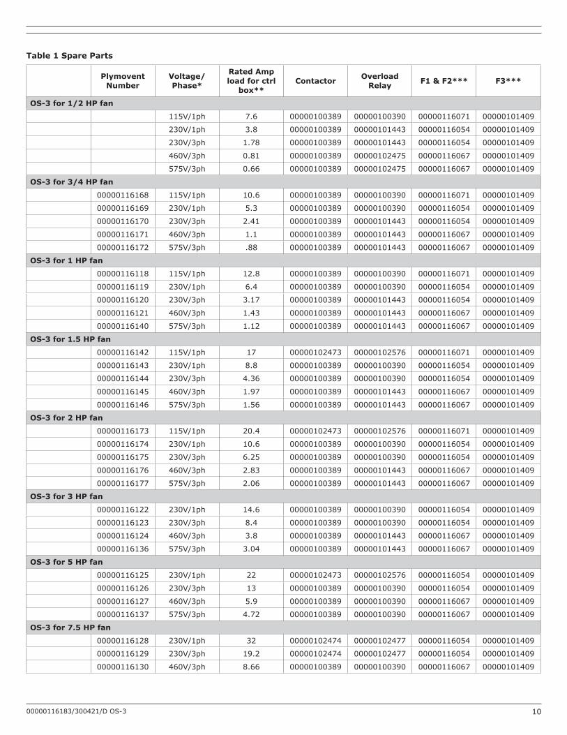
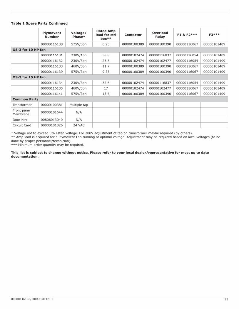
7 SPARE PARTS
PleaserefertoTable1onpage10toviewthesparepartsavailablefortheOS-3.
Fig.7.1 Exploded view
• A-F3• B-Transformer• C-F1/F2• D-Contactor• E-OverloadRelay• F-AdjustingHoleforTimer• G-CircuitBoard• H-Membrane
8 ELECTRICAL DIAGRAM
PleaserefertoFigures8.1-8.4(below)andFigure1onpage12 to viewtheelectricaldiagramsfortheOS-3.
Table2Aonpage13andTable2Bonpage14showtheFanComponentSizingChartsforthreeandonephase.
Fig.8.1 SwitchDetail
Fig.8.2 Terminal Detail
Fig.8.3 System Detail
9 DISPOSAL
Afterlifeoftheproduct,disposeitofinaccordancewithstateorlocalregulations.
00000116183/300421/D OS-3 10
Table 1 Spare Parts
Plymovent Number
Voltage/Phase*
Rated Amp load for ctrl
box**Contactor Overload
Relay F1 & F2*** F3***
OS-3 for 1/2 HP fan
115V/1ph 7.6 00000100389 00000100390 00000116071 00000101409
230V/1ph 3.8 00000100389 00000101443 00000116054 00000101409
230V/3ph 1.78 00000100389 00000101443 00000116054 00000101409
460V/3ph 0.81 00000100389 00000102475 00000116067 00000101409
575V/3ph 0.66 00000100389 00000102475 00000116067 00000101409
OS-3 for 3/4 HP fan
00000116168 115V/1ph 10.6 00000100389 00000100390 00000116071 00000101409
00000116169 230V/1ph 5.3 00000100389 00000100390 00000116054 00000101409
00000116170 230V/3ph 2.41 00000100389 00000101443 00000116054 00000101409
00000116171 460V/3ph 1.1 00000100389 00000101443 00000116067 00000101409
00000116172 575V/3ph .88 00000100389 00000101443 00000116067 00000101409
OS-3 for 1 HP fan
00000116118 115V/1ph 12.8 00000100389 00000100390 00000116071 00000101409
00000116119 230V/1ph 6.4 00000100389 00000100390 00000116054 00000101409
00000116120 230V/3ph 3.17 00000100389 00000101443 00000116054 00000101409
00000116121 460V/3ph 1.43 00000100389 00000101443 00000116067 00000101409
00000116140 575V/3ph 1.12 00000100389 00000101443 00000116067 00000101409
OS-3 for 1.5 HP fan
00000116142 115V/1ph 17 00000102473 00000102576 00000116071 00000101409
00000116143 230V/1ph 8.8 00000100389 00000100390 00000116054 00000101409
00000116144 230V/3ph 4.36 00000100389 00000100390 00000116054 00000101409
00000116145 460V/3ph 1.97 00000100389 00000101443 00000116067 00000101409
00000116146 575V/3ph 1.56 00000100389 00000101443 00000116067 00000101409
OS-3 for 2 HP fan
00000116173 115V/1ph 20.4 00000102473 00000102576 00000116071 00000101409
00000116174 230V/1ph 10.6 00000100389 00000100390 00000116054 00000101409
00000116175 230V/3ph 6.25 00000100389 00000100390 00000116054 00000101409
00000116176 460V/3ph 2.83 00000100389 00000101443 00000116067 00000101409
00000116177 575V/3ph 2.06 00000100389 00000101443 00000116067 00000101409
OS-3 for 3 HP fan
00000116122 230V/1ph 14.6 00000100389 00000100390 00000116054 00000101409
00000116123 230V/3ph 8.4 00000100389 00000100390 00000116054 00000101409
00000116124 460V/3ph 3.8 00000100389 00000101443 00000116067 00000101409
00000116136 575V/3ph 3.04 00000100389 00000101443 00000116067 00000101409
OS-3 for 5 HP fan
00000116125 230V/1ph 22 00000102473 00000102576 00000116054 00000101409
00000116126 230V/3ph 13 00000100389 00000100390 00000116054 00000101409
00000116127 460V/3ph 5.9 00000100389 00000100390 00000116067 00000101409
00000116137 575V/3ph 4.72 00000100389 00000100390 00000116067 00000101409
OS-3 for 7.5 HP fan
00000116128 230V/1ph 32 00000102474 00000102477 00000116054 00000101409
00000116129 230V/3ph 19.2 00000102474 00000102477 00000116054 00000101409
00000116130 460V/3ph 8.66 00000100389 00000100390 00000116067 00000101409
00000116183/300421/D OS-3 11
Plymovent Number
Voltage/Phase*
Rated Amp load for ctrl
box**Contactor Overload
Relay F1 & F2*** F3***
00000116138 575V/3ph 6.93 00000100389 00000100390 00000116067 00000101409
OS-3 for 10 HP fan
00000116131 230V/1ph 38.8 00000102474 00000116837 00000116054 00000101409
00000116132 230V/3ph 25.8 00000102474 00000102477 00000116054 00000101409
00000116133 460V/3ph 11.7 00000100389 00000100390 00000116067 00000101409
00000116139 575V/3ph 9.35 00000100389 00000100390 00000116067 00000101409
OS-3 for 15 HP fan
00000116134 230V/3ph 37.6 00000102474 00000116837 00000116054 00000101409
00000116135 460V/3ph 17 00000102474 00000102477 00000116067 00000101409
00000116141 575V/3ph 13.6 00000100389 00000100390 00000116067 00000101409
Common Parts
Transformer 00000100381 Multiple tap
Front panel Membrane 00000101644 N/A
Door Key 00806013040 N/A
Circuit Card 00000101326 24 VAC
*Voltagenottoexceed8%listedvoltage.For208Vadjustmentoftapontransformermayberequired(byothers).**AmploadisacquiredforaPlymoventFanrunningatoptimalvoltage.Adjustmentmayberequiredbasedonlocalvoltages(tobedonebyproperpersonnel/technician).***Minimumorderquantitymayberequired.
This list is subject to change without notice. Please refer to your local dealer/representative for most up to date documentation.
Table 1 Spare Parts Continued

00000116183/300421/D OS-3 12
Figure 1 Wiring Chart

00000116183/300421/D OS-3 13
Table 2A / Three Phase: Fan Component Sizing Chart
Plymovent Product No.
HPRating Voltage NEC Table 430.250Amps
WireSizeTHHNAWG
LengthofWireinFeet(Meters)StarttoFinish*
Circuit BreakerSize
From To*
FUA-1300-1-AM
1/2
208 2.4 14 0 478(145.6) 15A
FUA-1300-2-AM 230 2.2 14 0 576(175.5) 15A
460 1.1 14 0 2,306(702.8) 15A
575 .9 14 0 3,524(1,074) 15A
FUA-1800-1-AM
3/4
208 3.5 14 0 327(99.6) 15A
FUA-1800-2-AM 230 3.2 14 0 396(120.7) 15A
460 1.6 14 0 1,585(483.1) 15A
575 1.3 14 0 2,439(743.4) 15A
FUA-2100-1-AM
1
208 4.6 14 0 249(75.8) 15A
FUA-2100-2-AM 230 4.2 14 0 302(92) 15A
460 2.1 14 0 1,208(368.1) 15A
575 1.7 14 0 1,865(568.4) 15A
FUA-2700-1-AM
1.5
208 6.6 14 0 173(52.7) 15A
FUA-3000-1-AM 230 6 14 0 211(64.3) 15A
FUA-2700-2-AM 460 3 14 0 845(257.5) 15A
FUA-3000-2-AM 575 2.4 14 0 1,321(402.6) 15A
TEV-359-60 2
208 7.5 14 0 152(46.3) 15A
230 6.8 14 0 186(56.6) 15A
460 3.4 14 0 746(227.3) 15A
575 2.7 14 0 1,174(357.8) 15A
TEV-3110-60
3
208 10.6 14 0 108(32.9) 15A
FUA-4700-1-AM 230 9.6 14 0 132(40.2) 15A
FUA-4700-2-AM 460 4.8 14 0 528(160.9) 15A
575 3.9 14 0 813(247.8) 15A
TEV-559-60 5
208 16.7 10 0 173(52.7) 30A
230 15.2 12 0 132(40.2) 20A
460 7.6 14 0 333(101.4) 15A
575 6.1 14 0 519(158.1) 15A
TEV-585-60 7.5
208 24.2 8 0 191(58.2) 40A
230 22 10 0 146(44.5) 30A
460 11 14 0 230(70.1) 15A
575 9 14 0 352(107.2) 15A
TEV-745-60 10
208 30.8 8 0 150(45.7) 40A
230 28 8 0 182(55.4) 40A
460 14 12 0 287(87.4) 20A
575 11 14 0 288(87.7) 15A
TEV-768-60 15
208 46.2 6 0 158(48.1) 60A
230 42 6 0 193(58.8) 50A
460 21 10 0 305(92.9) 30A
575 17 10 0 472(143.8) 30A*Ifwirelengthislongerthandistancelisted,upsizetonextlargerAWGNote:Guidelinesaresubjecttochangewithoutnotice.Datasuppliedfromourprimarymotorsupplier.Pleaseconfirmattimeoforder.Plymoventassumesnoliabilityforanyelectricalinstallation,alllocal,city,andthe2014NationalElectricCodemustbefollowed.Thischartisaminimumstandardandtobeusedasaguidelineonly.Basedona3%voltagedropforbranchcircuits.

00000116183/300421/D OS-3 14
Table 2B / Single Phase: Fan Component Sizing Chart
Plymovent Product No.
HPRating Voltage NEC Table 430.248Amps
WireSizeTHHNAWG
LengthofWireinFeet(Meters)StarttoFinish*
Circuit BreakerSize
From To*
FUA-1301-AM 1/2
115 9.8 12 0 88(26.8) 20A
208 5.4 14 0 184(56) 15A
230 4.9 14 0 224(68.2) 15A
FUA-1801-AM 3/4
115 13.8 10 0 100(30.4) 30A
208 7.6 14 0 130(39.6) 15A
230 6.9 14 0 159(48.4) 15A
FUA-2101-AM 1
115 16 10 0 86(26.2) 30A
208 8.8 12 0 179(54.5) 20A
230 8 12 0 217(66.1) 20A
FUA-2701-AM
1.5
115 20 10 0 70(21.3) 30A
FUA-3001-AM 208 11 12 0 143(43.5) 20A
230 10 12 0 174(53) 20A
TEV-359-60 2
115 24 8 0 92(28) 40A
208 13.2 12 0 119(36.2) 20A
230 12 12 0 145(44.1) 20A
FUA-4701-AM
3
208 18.7 10 0 134(40.8) 30A
TEV-3110-60 230 17 10 0 163(49.6) 30A
460 ** 14 0 325(99) 15A
TEV-559-60 5
208 30.8 8 0 130(39.6) 40A
230 28 8 0 158(48.1) 40A
460 ** 14 0 209(63.7) 15A
TEV-585-60 7.5
208 44 6 0 144(43.8) 50A
230 40 6 0 175(53.3) 50A
460 ** 10 0 347(105.7) 30A
TEV-745-60 10
208 55 4 0 184(56) 60A
230 50 6 0 140(42.6) 60A
460 ** 10 0 286(87.1) 30A*Ifwirelengthislongerthandistancelisted,upsizetonextlargerAWG**2014NECTable430.248doesnotlist460voltsinglephasemotorsNote:Guidelinesaresubjecttochangewithoutnotice.Datasuppliedfromourprimarymotorsupplier.Pleaseconfirmattimeoforder.Plymoventassumesnoliabilityforanyelectricalinstallation,alllocal,city,andthe2014NationalElectricCodemustbefollowed.Thischartisaminimumstandardandtobeusedasaguidelineonly.Basedona3%voltagedropforbranchcircuits.

www.plymovent.com
00000116183/300421/DOS-3