Embed Size (px)
Citation preview

Operating instructionsORTOMAT-MTCType: O3G


1 42 3
7
5 6
8
9 10
11

Fig. 1
24
21 2322
Report
Server
Smartphone
Telecommunications antenna
ORTOMAT-MTC
PC
www.IDW.worldHYDROPORT
Tablet
Fig. 2

5
Contents
Dear customer,
Before using the ORTOMAT-MTC, hereinafter referred to as the measurement device, please read these operating instructions for information on commissioning, safety, intended use as well as cleaning and maintenance.
The figures referred to in these opera-ting instructions are the figures on the fold-out pages and inside pages of the cover.
Keep these operating instructions for future reference and pass them on to subsequent users of the measure-ment device.
General informationCopyright
This document is protected by copyright. Any duplication, reprint, even in extracts, or reproduction of the figures, even if modified, shall be permitted only with the prior written approval of the manufacturer.
Limitation of liability
All technical information, data and notes in these operating instructions regarding commissioning, operation and maintenance are the most recent at the time of going to print.
The manufacturer assumes no liability for damage caused as a result of failing to follow the operating instruc-tions, improper use, incorrect repairs, unauthorised changes or the use of non-approved replacement parts, accessories and tools.
Information on disposal
The packaging materials used are recyclable. Dispose of packa-
ging materials no longer required in accordance with local regulations.
General information . . . . . . . . . . . 5
Intended use . . . . . . . . . . . . . . . . . 7
Safety . . . . . . . . . . . . . . . . . . . . . . 7
Components/scope of delivery . . 9
Function description . . . . . . . . . 10
Preparations . . . . . . . . . . . . . . . . 11
Use . . . . . . . . . . . . . . . . . . . . . . . 15
Cleaning . . . . . . . . . . . . . . . . . . . 16
Maintenance . . . . . . . . . . . . . . . . 16
Storage . . . . . . . . . . . . . . . . . . . . 17
Customer service . . . . . . . . . . . . 17
Technical specifications . . . . . . 18
Index . . . . . . . . . . . . . . . . . . . . . . 20

6
Within the European Union, this product must not be disposed of with normal household waste.
Dispose of the measurement device in accordance with local regulations.
The batteries must not be disposed of with household waste. Dispose of the batteries in ac-cordance with local regulations
for the disposal of rechargeable batte-ries/used batteries or special waste.
INFORMATION
You can take the measurement de-vice to your nearest service point for correct, environmentally-responsible disposal.
Warnings
The following warnings are used in these operating instructions:
WARNING
A warning of this danger level indicates a potentially hazardous situation .
If the hazardous situation is not avoided, this may result in death or serious injury.
► Follow the instructions in this warning to avoid causing perso-nal injury.
CAUTION
A warning of this danger level indicates possible material dama-ge .
If the situation is not avoided, it could result in material damage.
► Follow the instructions in this warning to avoid causing materi-al damage.
INFORMATION
An information box provides additio-nal information to enable easier use and handling of the measurement device.

7
Intended useThe measurement device is intended exclusively for the acoustic detection of leaks in pressurised water pipes.
Any other use or use beyond that which is specified does not constitute intended use.
Foreseeable misuse, improper use
Any use for a purpose other than that mentioned above is considered to be improper use.
The operator alone bears the risk as-sociated with improper use or misuse.
Misuse is considered to take place, for example, when
– The information in these operating instructions is not followed.
– Batteries are not inserted with the correct polarity, or impermissible batteries are used.
Claims of any kind due to damage caused by improper use are exclu-ded.
The operator alone shall bear the risk.
INFORMATION
Ensure that accident prevention regulations and the Ordinance on Industrial Safety and Health are complied with if the device is used for commercial purposes.
SafetyObserve the following basic safety measures to avoid the risk of fire, injury and material damage.
Basic safety information
– Do not use the measurement device in a potentially explosive atmosphere.
– Have repairs to the measurement device or to the accessories car-ried out exclusively by an authori-sed specialist workshop or by the factory service centre.
– Repairs to the measurement device during the warranty period must be made by a service centre authorised by the manufacturer, otherwise the warranty claim shall be invalid.
– Defective components must be exchanged only for original repla-cement parts. Only by using these parts can it be guaranteed that the safety requirements are met.

8
– Store the measurement device and the accessories in a dry, clean and temperature-controlled locati-on out of the reach of children.
– The connections and the battery cover on the measurement device must always be correctly sealed and protected if they are exposed to moisture or dirt.
– Wear personal protective equip-ment in accordance with local guidelines and conditions, in parti-cular when used on busy roads.
Safety information for batteries
WARNING
If batteries are used incorrectly, there is a risk of fire, explosion and injury .
Proceed in accordance with the following safety information in order to avoid injuring yourself or others:
► Batteries must not be opened, thrown into a fire, immersed in any liquids or short-circuited.
► Battery fluid can leak from da-maged batteries. If the batteries have leaked, do not let skin, eyes or mucous membranes come into contact with the bat-tery fluid. If contact with battery fluid is made, rinse the affected areas immediately with plenty of clean water and seek medical attention straight away.
► If batteries are damaged or used incorrectly, vapours can be emit-ted. Ventilate the area with fresh air and seek medical attention if you feel unwell. The vapours could irritate the respiratory system.

9
CAUTION
Possible material damage if bat-teries are used incorrectly .
Proceed in accordance with the fol-lowing information to avoid material damage:
► Use only the battery type appro-ved by the manufacturer.
► Remove leaking batteries imme-diately from the measurement device.
► Ensure that the battery connec-tor is connected correctly.
INFORMATION
Remove the batteries from the measurement device if the mea-surement device is not used for an extended period.
The batteries must not be dispo-sed of with household waste. For more information on disposal, see the section entitled „Information on disposal“.
Components/scope of deli-veryDevice overview
1 Rating plate
2 Magnetic adapter
3Installation position for magnetic adapter
4 IR glass with LED
5 Connector socket for antenna
6 Connector socket for vibraphone
7 Battery compartment cover
8 Battery
9 Position label with position number
10Magnetic sensor for the magnetic control function
11 Electronics, encapsulated
Scope of delivery
21 ORTOMAT-MTC data logger, complete with integrated battery
22 Magnetic adapter
23 Antenna
24 PE vibraphone with connecting cable (cable with integrated FM antenna)
25 Operating instructions
Rating plate
The rating plate (1) specifies the follo-wing information:
– Type of measurement device
– Serial number
– Manufacturer data
Label
The position number of the measu-rement device, which increases in the system, is shown on the position label.

10
Transport inspection
The measurement device is supplied as standard with the components specified in the section entitled „Sco-pe of delivery“.
INFORMATION
Check that the delivery is complete and free from visible damage. Con-tact your dealer/supplier immedia-tely if your delivery is incomplete or damaged.
Function descriptionHow it works
The ORTOMAT-MTC is an acoustic measurement device for detecting leaks in pressurised water pipes. A vibraphone picks up noises from the water pipes under inspection (24 hours). Correlation technology can be used to accurately detect the leak site between two measurement devices. The measurement results are automatically sent to the server at the set times. The evaluated data is available online in HYDROPORT at all times. Here, noise level results and correlatable audio files are available to the user.
The loudest noises reveal the location of the leak.
Power is supplied to the measure-ment device by batteries.
Measuring principle
The measurement device records the noises which are produced at the measuring point for 24 hours, with the times in which little water is consu-med being checked in particular (main measurement). The measurement device records the leak noises in the pipeline network using the highly sen-sitive vibraphone. Correlatable audio files are also recorded in addition to the noise levels in order to precisely detect leak sites.

11
Data transfer (see fig . 2)
Data is transferred from the measure-ment device to the web server com-pletely automatically. Newly detected leak sites can be reported immedia-tely. To transfer the data, the measu-rement device accesses the existing broadband mobile networks, and no radio repeaters or wireless networks need to be set up. Likewise, the mea-surement devices no longer have to be removed for reprogramming and for firmware updates. Instead, they can be converted or updated cent-rally by the server using over-the-air programming (OTA/FOTA). Potential reprogramming of the measurement device via OAT must be performed by an expert.
PreparationsSelecting the measuring points
INFORMATION
The measuring points must have a large quantity of pipe material to monitor (T-piece/crosspiece).
Do not use any dead-end branch pipes if possible.
Maintain a distance from measure-ment device to measurement device of approximately 200 m for metallic pipelines and approximately 100 m for plastic pipelines.
The acoustic measurement on the water pipe can be taken at various measuring points:
�Gate valve (access cover)
�Hydrant
�Shaft with direct access to the pipe
�Service supply
The vibraphone (24) (noise sensor) should have an optimum mechanical connection to the pipeline.
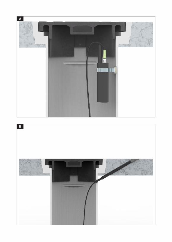
Antenna installation
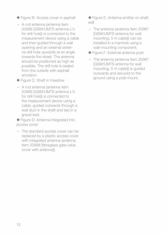
Depending on the selected measuring location, different types of antenna and different installation types can or must be used:
�Figure A: Access cover
– The rod antenna supplied (antenna item 20982 [GSM/UMTS antenna, dipole 1/4 flex, SMAm]) is connec-ted to the measurement device itself.
12
�Figure B: Access cover in asphalt
– A rod antenna (antenna item 20999 [GSM/UMTS antenna λ½ for drill hole]) is connected to the measurement device using a cable and then guided through a wall opening and an external anten-na drill hole upwards at an angle towards the street. The antenna should be positioned as high as possible. The drill hole is sealed from the outside with asphalt emulsion.
�Figure C: Shaft in meadow
– A rod antenna (antenna item 20999 [GSM/UMTS antenna λ½ for drill hole]) is connected to the measurement device using a cable, guided outwards through a wall duct in the shaft and laid in a gravel bed.
�Figure D: Antenna integrated into access cover
– The standard access cover can be replaced by a plastic access cover with integrated antenna (antenna item 20998 [fibreglass gate valve cover with antenna]).
�Figure E: Antenna emitter on shaft wall
– The antenna (antenna item 20987 [GSM/UMTS antenna for wall mounting, 5 m cable]) can be installed in a manhole using a wall-mounting component.
�Figure F: External antenna post
– The antenna (antenna item 20987 [GSM/UMTS antenna for wall mounting, 5 m cable]) is guided outwards and secured to the ground using a pole mount.
13
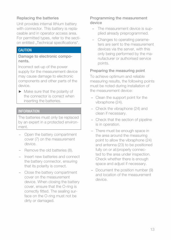
Replacing the batteries
Unit provides internal lithium battery with connector. This battery is repla-ceable and in operator access area. For permitted types, refer to the secti-on entitled „Technical specifications“.
CAUTION
Damage to electronic compo-nents .
Incorrect set-up of the power supply for the measurement device may cause damage to electronic components and other parts of the device.
► Make sure that the polarity of the connector is correct when inserting the batteries.
INFORMATION
The batteries must only be replaced by an expert in a protected environ-ment.
– Open the battery compartment cover (7) on the measurement device.
– Remove the old batteries (8).
– Insert new batteries and connect the battery connector, ensuring that its polarity is correct.
– Close the battery compartment cover on the measurement device. When closing the battery cover, ensure that the O-ring is correctly fitted. The sealing sur-face on the O-ring must not be dirty or damaged.
Programming the measurement device
– The measurement device is sup-plied already preprogrammed.
– Changes to operating parame-ters are sent to the measurement devices via the server, with this only being performed by the ma-nufacturer or authorised service points.
Preparing the measuring point
To achieve optimum and reliable measuring results, the following points must be noted during installation of the measurement device:
– Clean the support point for the vibraphone (24).
– Check the vibraphone (24) and clean if necessary.
– Check that the section of pipeline is in operation.
– There must be enough space in the area around the measuring point to allow the vibraphone (24) and antenna (23) to be positioned fully on or at/properly connec-ted to the area under inspection. Check whether there is enough space and adjust if necessary.
– Document the position number (9) and location of the measurement device.

14
Preparing the measurement device for use
– Check the antenna installation, see the section entitled „Antenna installation“.
– Check the support point for the vibraphone (24).
– Connect the vibraphone to the connection (6) on the measure-ment device.
– Connect the antenna (23) to the connection (5) on the measure-ment device.
– Always activate the measurement device once using a magnet be-fore installing it in a shaft (see the section entitled „Magnetic control function“). This deactivates a transport cutout if one is fitted. A test function is additionally initiated.
– Check that the battery cover is securely fitted.
– Fit the magnetic adapter (22) to the installation position (3) of the measurement device.
INFORMATION
When used in a deep shaft, the measurement device must be in-stalled as high as possible, near the cover. It may be necessary to guide the vibraphone to the support point via an extension cable.
Prevent the measurement device from falling into the shaft.
If a vibraphone cable longer than 45 cm is used, an FM adapter cable (30 cm) must be connected bet-ween the measurement device and vibraphone cable.
– The FM antenna integrated into the vibraphone cable (24) should always be positioned as high as possible in the shaft. The connec-tor sockets (5 and 6) should face upwards towards the shaft opening.
INFORMATION
At the measuring point, define the FM radio channel with the best reception for the location. All measurement devices in the same system must use the same FM radio channel.
The FM radio channel can be adjusted after installation via OTA programming.
15
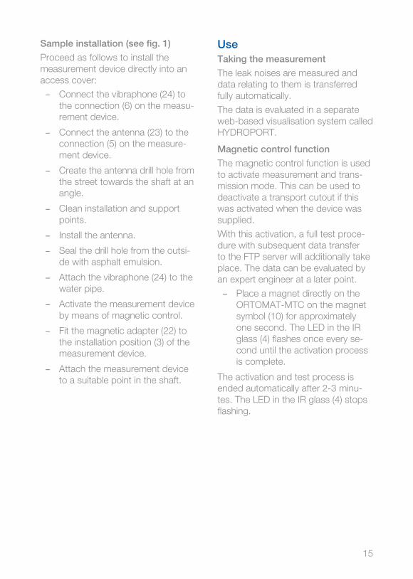
UseTaking the measurement
The leak noises are measured and data relating to them is transferred fully automatically.
The data is evaluated in a separate web-based visualisation system called HYDROPORT.
Magnetic control function
The magnetic control function is used to activate measurement and trans-mission mode. This can be used to deactivate a transport cutout if this was activated when the device was supplied.
With this activation, a full test proce-dure with subsequent data transfer to the FTP server will additionally take place. The data can be evaluated by an expert engineer at a later point.
– Place a magnet directly on the ORTOMAT-MTC on the magnet symbol (10) for approximately one second. The LED in the IR glass (4) flashes once every se-cond until the activation process is complete.
The activation and test process is ended automatically after 2-3 minu-tes. The LED in the IR glass (4) stops flashing.
Sample installation (see fig . 1)
Proceed as follows to install the measurement device directly into an access cover:
– Connect the vibraphone (24) to the connection (6) on the measu-rement device.
– Connect the antenna (23) to the connection (5) on the measure-ment device.
– Create the antenna drill hole from the street towards the shaft at an angle.
– Clean installation and support points.
– Install the antenna.
– Seal the drill hole from the outsi-de with asphalt emulsion.
– Attach the vibraphone (24) to the water pipe.
– Activate the measurement device by means of magnetic control.
– Fit the magnetic adapter (22) to the installation position (3) of the measurement device.
– Attach the measurement device to a suitable point in the shaft.

16
CleaningCAUTION
Damage due to improper clea-ning .
Improper cleaning can cause dama-ge to the measurement device.
► When immersing the measure-ment device in water, the battery compartment cover (7), the connector socket for the vibra-phone (6) and the connector socket for the antenna (5) must always be protected and correc-tly sealed.
► Only use cleaning agents which are compatible with plastic.
After each use
– Clean the measurement device and the accessories used (mag-netic adapter) with a damp cloth.
MaintenanceVisual checks during each use:
– Check the measurement device and the accessories used for any signs of external damage.
– Clean the measurement device as described in the section entitled „Cleaning“.
Device servicing
It is recommended that you have your device serviced by the Customer Service department at least every four years.
Device servicing comprises the follo-wing tasks:
– System inspection and inventory.
– Cleaning the device and re-label-ling if required.
– Replacing the internal batteries.
– Firmware update for the measure-ment device.
– Checking that data transfer is working properly.
– Reprogramming the operating parameters.
– Sensor test, functional check and replacement of wear parts, if required.

17
StorageIf you do not need the measurement device for an extended period, clean it as described in the section entitled „Cleaning“. Store the measurement device and all accessories in a dry, clean and frost-free location.
INFORMATION
Remove the batteries from the measurement device if the mea-surement device is not used for an extended period.
The batteries must not be dispo-sed of with household waste. For more information on disposal, see the section entitled „Information on disposal“.
Customer serviceShould you have any questions for the Customer Service department, please contact:
vonRoll hydro (suisse) agRüeggisingerstr. 2CH-6020 EmmenbrückeSwitzerland
or your sales outlet/dealer.
18
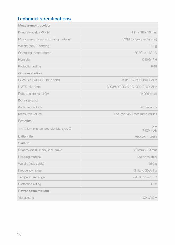
Technical specificationsMeasurement device:
Dimensions (L x W x H) 131 x 38 x 36 mm
Measurement device housing material POM (polyoxymethylene)
Weight (incl. 1 battery) 178 g
Operating temperatures -20 °C to +60 °C
Humidity 0-99% RH
Protection rating IP68
Communication:
GSM/GPRS/EDGE, four-band 850/900/1800/1900 MHz
UMTS, six-band 800/850/900/1700/1900/2100 MHz
Data transfer rate IrDA 19,200 baud
Data storage:
Audio recordings 28 seconds
Measured values The last 2450 measured values
Batteries:
1 x lithium-manganese dioxide, type C3 V
7400 mAh
Battery life Approx. 4 years
Sensor:
Dimensions (H x dia.) incl. cable 90 mm x 40 mm
Housing material Stainless steel
Weight (incl. cable) 630 g
Frequency range 3 Hz to 3000 Hz
Temperature range -20 °C to +70 °C
Protection rating IP68
Power consumption:
Vibraphone 100 µA/5 V
19
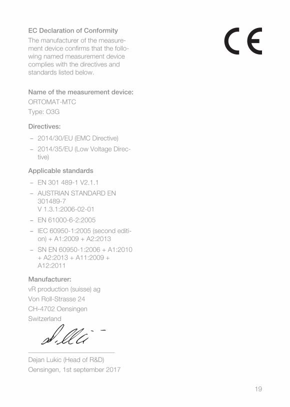
EC Declaration of Conformity
The manufacturer of the measure-ment device confirms that the follo-wing named measurement device complies with the directives and standards listed below.
Name of the measurement device:
ORTOMAT-MTC
Type: O3G
Directives:
– 2014/30/EU (EMC Directive)
– 2014/35/EU (Low Voltage Direc-tive)
Applicable standards
– EN 301 489-1 V2.1.1
– AUSTRIAN STANDARD EN 301489-7 V 1.3.1:2006-02-01
– EN 61000-6-2:2005
– IEC 60950-1:2005 (second editi-on) + A1:2009 + A2:2013
– SN EN 60950-1:2006 + A1:2010 + A2:2013 + A11:2009 + A12:2011
Manufacturer:
vR production (suisse) ag
Von Roll-Strasse 24
CH-4702 Oensingen
Switzerland
__________________________
Dejan Lukic (Head of R&D)
Oensingen, 1st september 2017

20
Index
BIntended use ................................. 7
EEC Declaration of Conformity ....... 19
GDevice overview ............................. 9
KCustomer service ........................ 17
LScope of delivery ........................... 9
MMagnetic control function ............ 15
RCleaning ...................................... 16
SSafety ............................................ 7
WMaintenance ..................................16
A
B

C
D

F
E

vonRoll hydro (suisse) ag | Rüeggisingerstr. 2 | 6020 Emmenbrücke | Switzerland Tel. +41 (0) 41 268 66 77 | Fax +41 (0) 41 268 66 [email protected] | www .vonroll-hydro .ch
A vonRoll infratec Group company