Embed Size (px)
Citation preview

ORTHOGRAPHICPROJECTION
C H A P T E R S I X
OBJECTIVES1. Recognize and sketch the symbol for third-angle projection.
2. List the six principal views of projection.
3. Sketch the top, front, and right-side views of an object withnormal, inclined, and oblique surfaces.
4. Understand which views show depth in a drawing showing top,front, and right-side views.
5. Know the meaning of normal, inclined, and oblique surfaces.
6. Compare using a 2D CAD program with sketching on a sheetof paper.
7. List the dimensions that transfer between top, front, andright-side views.
8. Transfer depth between the top and right-side views.
9. Label points where surfaces intersect.
10. Select a good arrangement of generated 2D drawing views to place from a 3D model.

UNDERSTANDING PROJECTIONSTo make and interpret drawings you need to know how to createprojections and understand the standard arrangement of views.
You also need to be familiar with the geometry of solid objects and be able to visualize a 3D object that is represented in a 2D sketch or drawing.

Views of ObjectsThe system of views is called multiview projection. Each view provides certain definite information. For example, a front view shows the true shape and size of surfaces that are parallel to the front of the object.

Multiview ProjectionThe system of views is called multiview projection. Each view provides certain definite information.
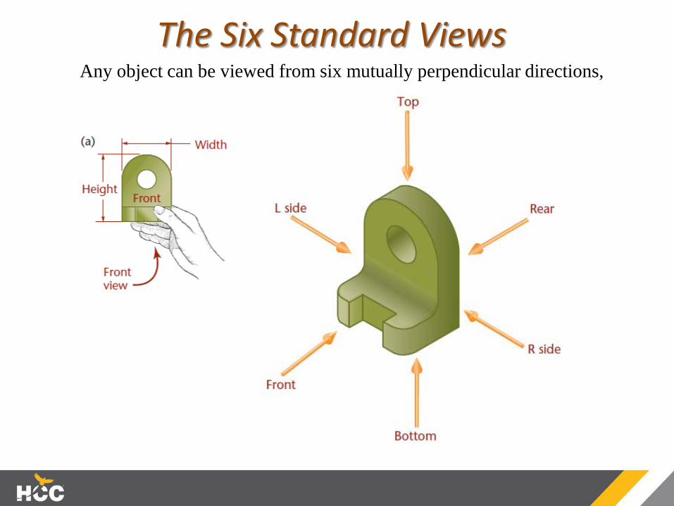
The Six Standard ViewsAny object can be viewed from six mutually perpendicular directions,
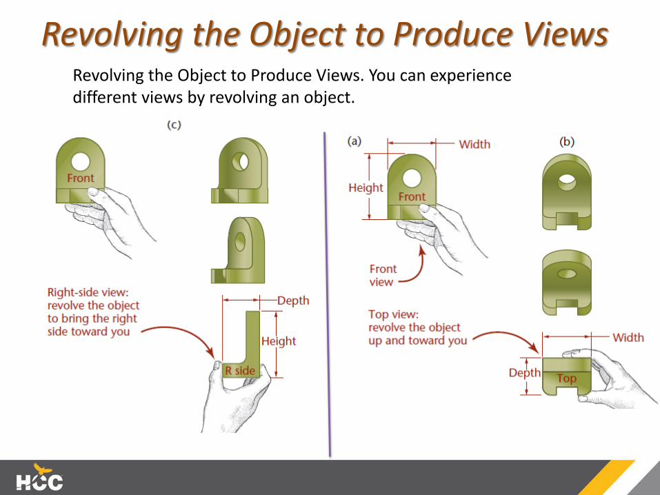
Revolving the Object to Produce ViewsRevolving the Object to Produce Views. You can experience different views by revolving an object.

Principal DimensionsThe three principal dimensions of an object are width, height, and depth.
The front view shows only the height and width of the object and not the depth. In fact, any principal view of a 3D object shows only two of the threeprincipal dimensions; the third is foundin an adjacent view. Height is shown inthe rear, left-side, front, and right-sideviews. Width is shown in the rear, top,front, and bottom views. Depth isshown in the left-side, top, right-side,and bottom views.

Projection Method
Projection of an Object
The outline on the plane of projection shows how the object appears to the observer. In orthographic projection, rays (or projectors) from all points on the edges or contours of the object extend parallel to each other and perpendicular to the plane of projection. The word orthographic means “at right angles.”

Horizontal and Profile Projection PlanesSpecific names are given to the planes of projection. The front view is projected to the frontal plane. The top view is projected to the horizontal plane. The side view is projected to the profile plane.

The Glass BoxOne way to understand the standard arrangement of views on the sheet of paper is to envision a glass box.
If planes of projection were placed parallel to each principal face of the object, they would form a box.

Unfolding the Glass Box
To organize the views of a 3D object on a flat sheet of paper, imagine the six planes of the glass box being unfolded to lie flat.
Note the six standard views (front, rear, top, bottom, right side, left side).

The Glass Box UnfoldedLines extend around the glass box from one view to another on the planes of projection. These are the projectors from a point in one view to the same point in another view.

The Orthographic ProjectionThe front, top, and right-side views of the object shown now without the folding lines.
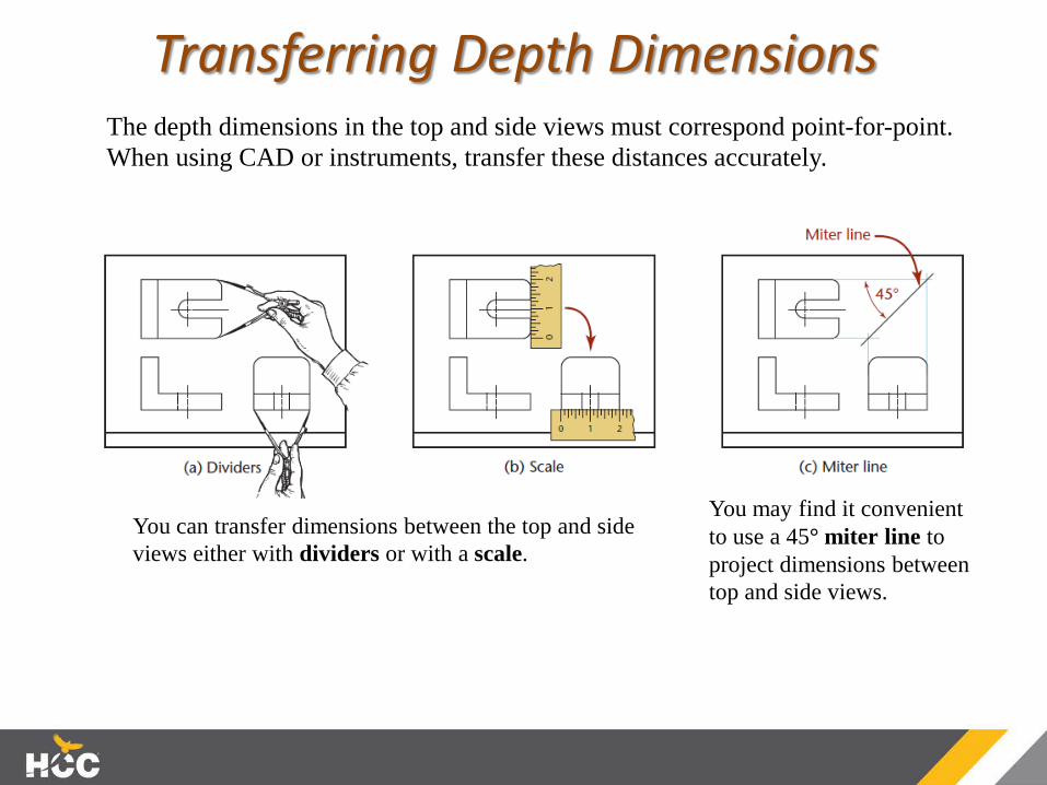
Transferring Depth Dimensions
You can transfer dimensions between the top and side views either with dividers or with a scale.
The depth dimensions in the top and side views must correspond point-for-point. When using CAD or instruments, transfer these distances accurately.
You may find it convenient to use a 45° miter line to project dimensions between top and side views.
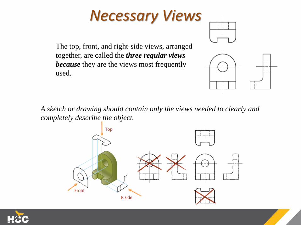
Necessary Views
The top, front, and right-side views, arranged together, are called the three regular views because they are the views most frequently used.
A sketch or drawing should contain only the views needed to clearly and completely describe the object.
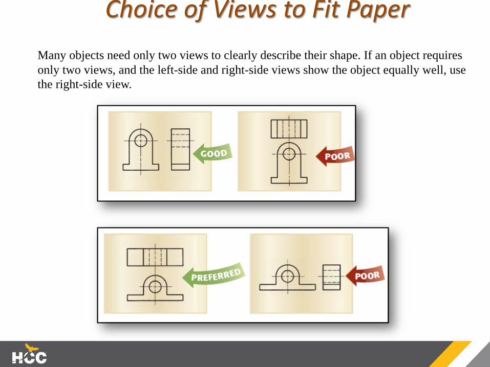
Choice of Views to Fit Paper Many objects need only two views to clearly describe their shape. If an object requires only two views, and the left-side and right-side views show the object equally well, use the right-side view.

One-ViewOften, a single view supplemented by a note or by lettered symbols isEnough.
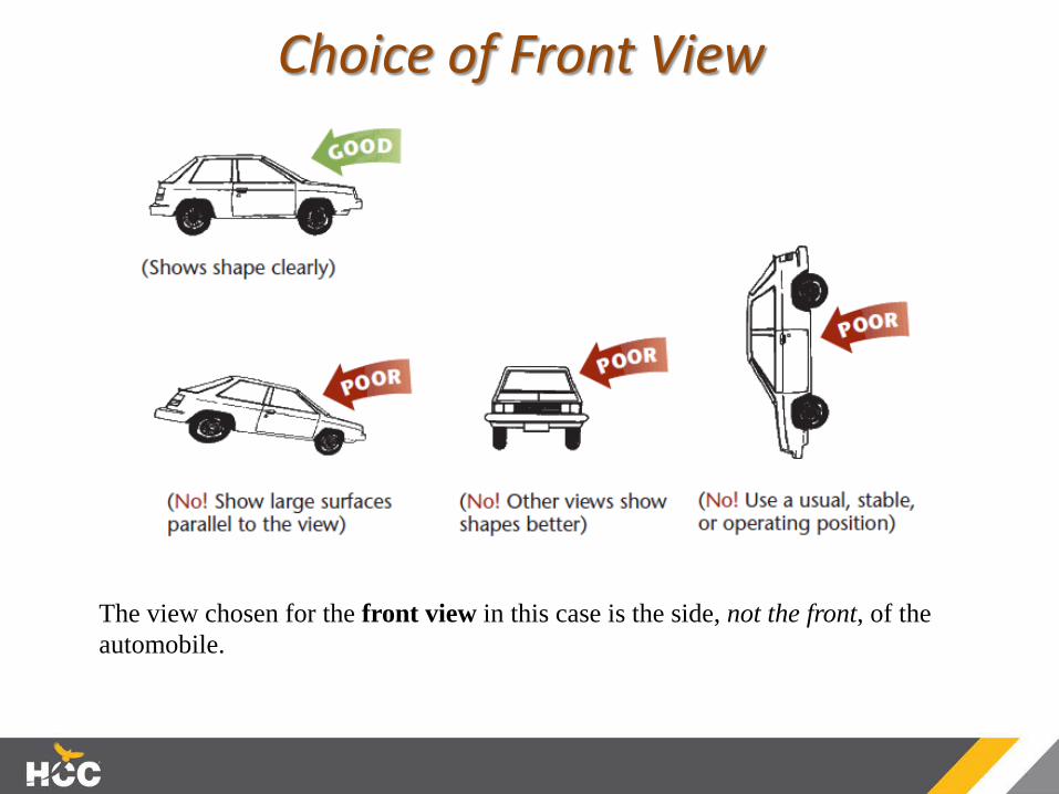
Choice of Front View
The view chosen for the front view in this case is the side, not the front, of the automobile.
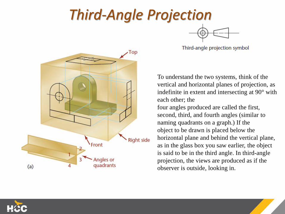
Third-Angle Projection
To understand the two systems, think of the vertical and horizontal planes of projection, as indefinite in extent and intersecting at 90° with each other; thefour angles produced are called the first, second, third, and fourth angles (similar to naming quadrants on a graph.) If theobject to be drawn is placed below the horizontal plane and behind the vertical plane, as in the glass box you saw earlier, the object is said to be in the third angle. In third-angle projection, the views are produced as if the observer is outside, looking in.
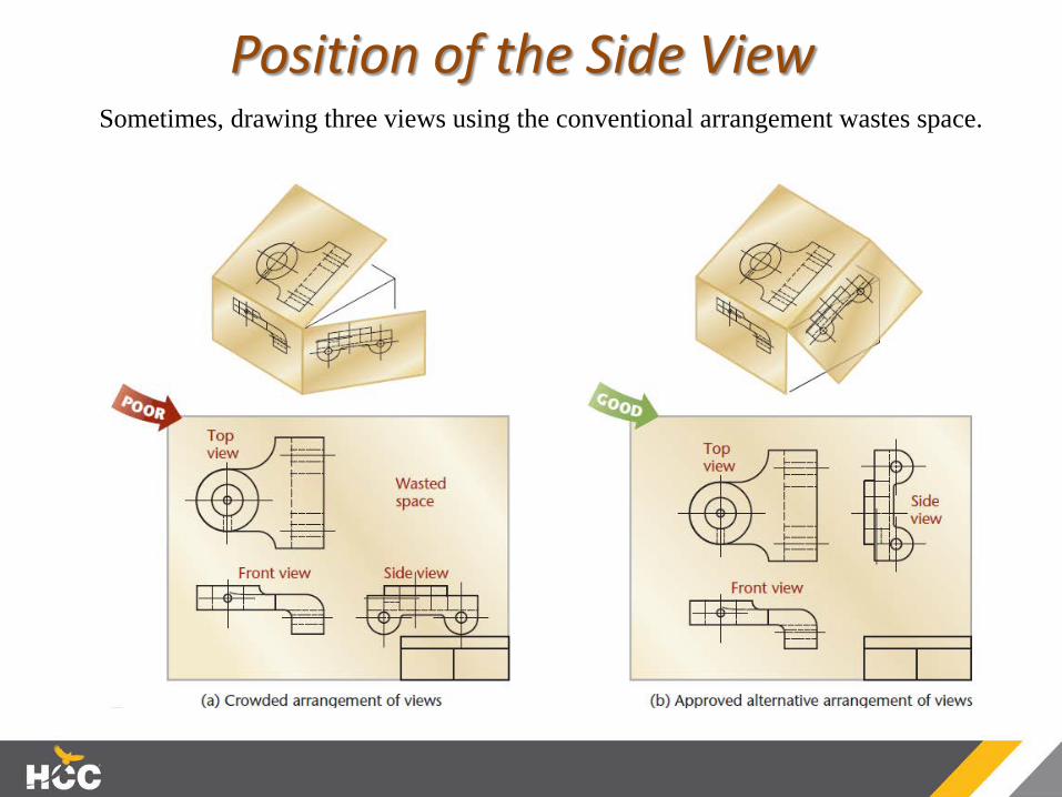
Position of the Side ViewSometimes, drawing three views using the conventional arrangement wastes space.

First-Angle ProjectionIf the object is placed above the horizontal plane and in front of the vertical plane, the object is in the first angle.
The biggest difference between third-angle projection and first-angle projection is how the planes of the glass box are unfolded.

Hidden LinesThick, dark lines represent features of the object that are directly visible. Dashed lines represent features that would be hidden behind other surfaces.
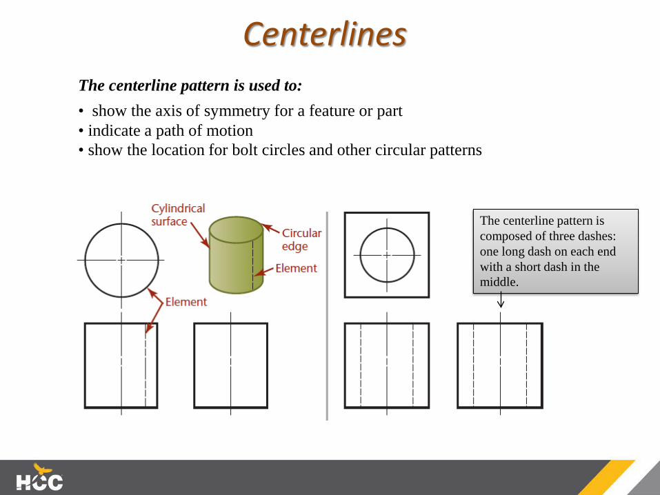
CenterlinesThe centerline pattern is used to:• show the axis of symmetry for a feature or part• indicate a path of motion• show the location for bolt circles and other circular patterns
The centerline pattern is composed of three dashes: one long dash on each end with a short dash in the middle.

PRECEDENCE OF LINESA visible line always takes precedence over and covers up a centerline or a hidden line when they coincide in a view (A and B).
A hidden line takes precedence over a centerline (C).

Centerlines continued…Centerlines (symbol: ) are used to indicate symmetrical axes of objects or features, bolt circles, and paths of motion.

DEVELOPING VIEWS FROM 3D MODELS
Orthographic Views and Shaded Pictorial View Generated from the Part Model (Courtesy of Dynojet Research, Inc.)

Placing the Views
Spacing Drawing Views
As you plan the views to be included, allow for plenty of white space on the drawing. Leave room for dimensions between the views, and separate the views from one another with white space. The space between drawing views does not have to be equal, yet the views should appear to be related. Do not space them too far apart. If there is not enough white space in your drawing, or if the views are too small to see the details clearly, consider using a larger sheet size

Isometric Views Including isometric views in detail drawings helps others easily interpret the drawing. Isometric views are often shown in the upper right-hand area of the drawing, as there is often room there. The isometric view does not have to be at the same scale as the other views.
The isometric view provides an easy visual reference for the part described in the orthographic views.
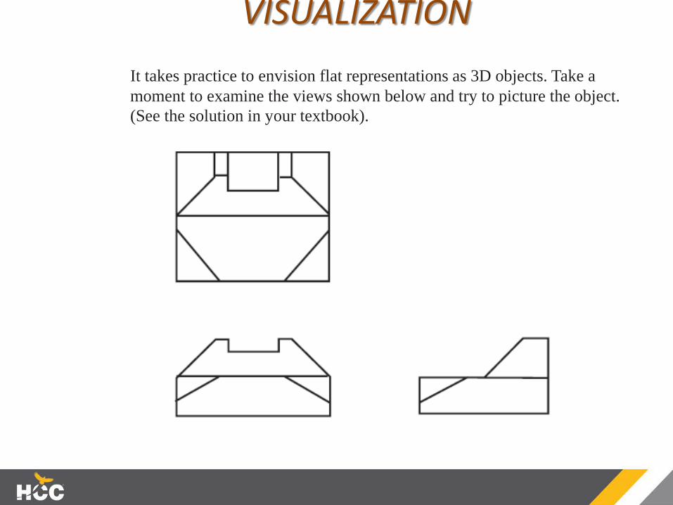
VISUALIZATION It takes practice to envision flat representations as 3D objects. Take a moment to examine the views shown below and try to picture the object. (See the solution in your textbook).

VIEWS OF SURFACESThere are terms used for describing a surface’s orientation to the plane of projection. The three orientations that a plane surface can have to the plane of projection are normal, inclined, and oblique.
Note how a plane surface that is perpendicular to a plane of projectionappears on edge as a straight line
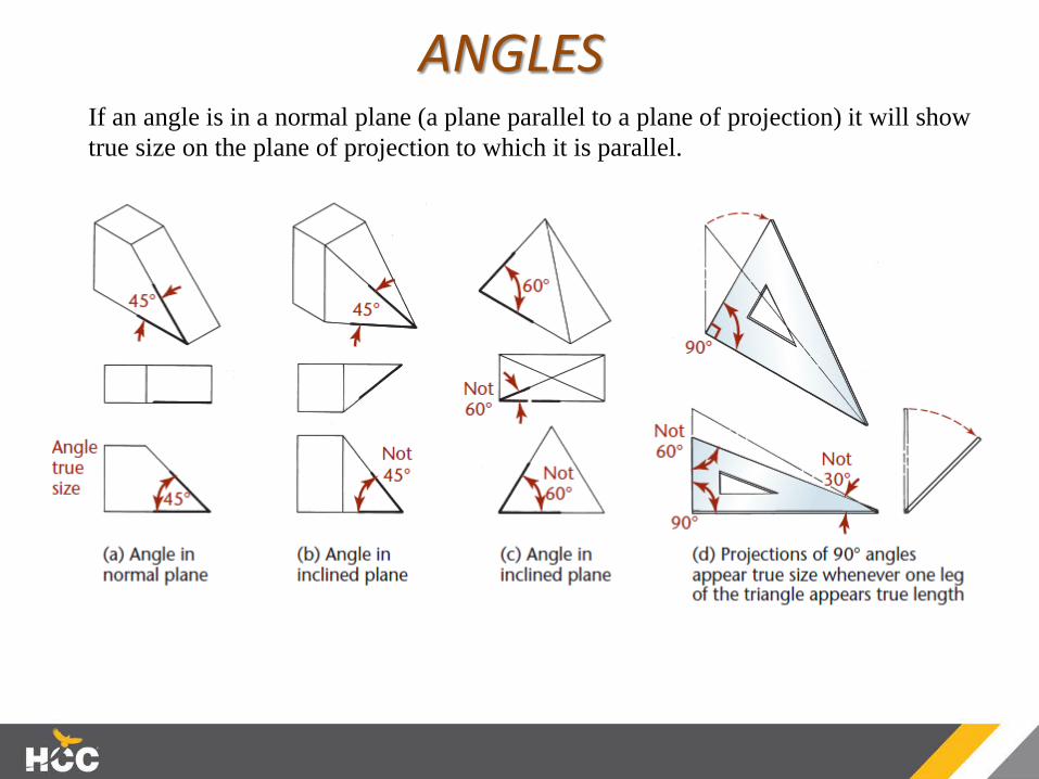
ANGLESIf an angle is in a normal plane (a plane parallel to a plane of projection) it will show true size on the plane of projection to which it is parallel.
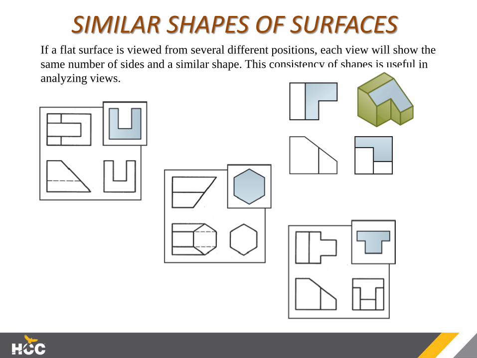
SIMILAR SHAPES OF SURFACESIf a flat surface is viewed from several different positions, each view will show the same number of sides and a similar shape. This consistency of shapes is useful in analyzing views.

INTERPRETING VIEWSOne method of interpreting sketches is to reverse the mental process used in projecting them.
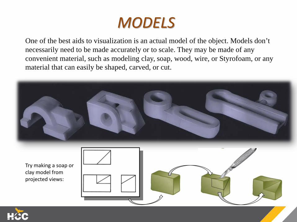
MODELSOne of the best aids to visualization is an actual model of the object. Models don’t necessarily need to be made accurately or to scale. They may be made of any convenient material, such as modeling clay, soap, wood, wire, or Styrofoam, or any material that can easily be shaped, carved, or cut.
Try making a soap or clay model from projected views: