Embed Size (px)
Citation preview

Orthographic Projection

Orthographic projection is a method of producing a number of
separate two-dimensional inter-related views, which are mutually at right angles to
each other. Using this projection, even the most complex shape can be fully described.
Orthographic projection is based on
two principal planes — one horizontal
(HP) and one vertical (VP) —
intersecting each other
Why Orthographic Projection is used in technical drawing
3-D projections are useful in that they provide an image that is similar to the image in
the designer’s mind’s eye. But 3-D projections are often weak in providing adequate
details of the object, and there is often some distortion of the object.
For instance, a circular hole becomes an ellipse in an isometric 3-D projection.
Orthographic projection are used to overcome the weaknesses of 3-D projections.
Orthographic projections are a collection of flat 2-D drawings of the different sides of
an object.

Orthographic projection is a parallel projection technique
in which the parallel lines of sight are perpendicular to the
projection plane 3-D projections are useful in that they provide an
image that is similar to the image in the designer’s
mind’s eye. But 3-D projections are often weak in
providing adequate details of the object, and there is
often some distortion of the object.
For instance, a circular hole becomes an ellipse in
an isometric 3-D projection. Orthographic
projection are used to overcome the weaknesses
of 3-D projections. Orthographic projections are a
collection of flat 2-D drawings of the different sides
of an object.
Orthographic view

Orthographic view depends on relative position of the object to
the line of sight. It uses multiple views of the object, from points of
view rotated about the object's center through increments of 90°.
The views may be
considered to be obtained
by rotating the object
about its center through
increments of 90°.
Orthographic view

It represents accurate shape and size. Advantage
Disadvantage Require practice in writing and reading.
Multiviews drawing (2-view drawing) Example
Orthographic View

Only two forms of orthographic
projections are used: first-angle
projection (‘European ISO-E’)
and third-angle projection
(‘American ISO-A’).
On engineering drawings, the
projection angle is
denoted by an international
symbol consisting of
a truncated cone, respectively
for first-angle
(FR) and third-angle (US):
(‘European ISO-E’) (‘American ISO-A’)
Orthographic View

STEP 1 : Orient the Object
NO !
Orient the object to the best position relative to a glass box. The
object should presents its features in actualsize and shape
in orthographic views.
GOOD
View Selection Steps
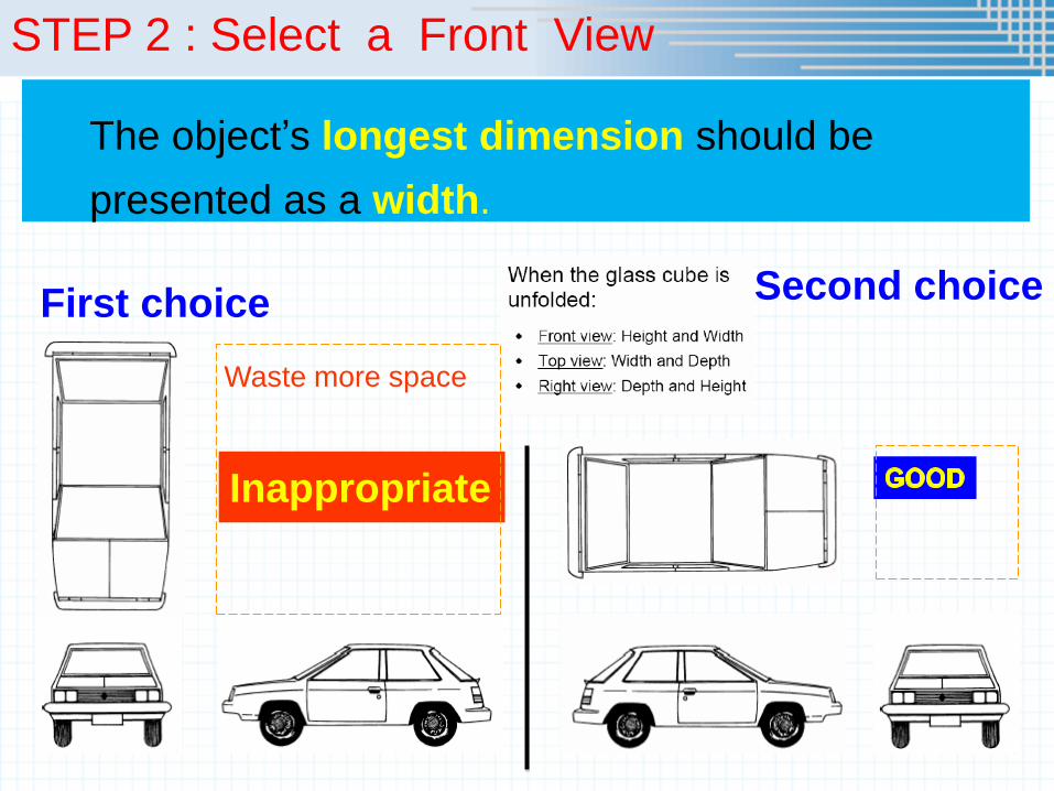
STEP 2 : Select a Front View
The object’s longest dimension should be
presented as a width.
Inappropriate
First choice Second choice
Waste more space

STEP 2 : Select a Front View
Choose the view that have the fewest number of
hidden lines.
GOOD Inappropriate

STEP 3 : Select an Adjacent View
GOOD
Inappropriate
Inappropriate
GOOD
Choose the view that have the fewest number of
hidden lines and minimum number of views that
can represent the major features of the object

Object Features
Edges are lines that represent the boundary
between two faces.
Corners Represent the intersection of two or
more edges.
Edge
Corner
Edge No edge
No corner No corner

Surfaces are areas that are bounded by edges
or limiting element.
Limiting
element
is a line that represents the last visible
part of the curve surface.
Surface Surface Surface
Limit Limit
Object Features

Standard Views of Primitive Solids

Fillets, Rounds & Chamfers

Edge Lines – Principal & Inclined
Principal lines appear vertical,
horizontal or as point views.
Inclined lines appear inclined in
one view.
2
Edge lines are lines that
represent the boundary
between two faces

Edge Lines – Oblique
Oblique line appears inclined in all views

Type of Planes
Principal
Oblique
Inclined Oblique
surface

Principal Planes Principle planes are parallel to principal orthographic
planes
Principal planes appear in true
size in one plane and as an
edge view in the other two
planes.

Inclined Planes
Inclined planes are perpendicular to two opposite
orthographic planes.

Oblique Planes
Oblique planes are neither parallel nor
perpendicular to any principal orthographic planes.
Oblique
surface

Top view


Standards are set of rules that govern how Technical
drawings are represented.
Drawing standards are used so that drawings convey
the same meaning to everyone who reads them.
Basic Line Types

Basic Line Types
Types of Lines Appearance Name according
to application
Continuous thick line Visible line
Continuous thin line Dimension line
Extension line
Leader line
Dash thick line Hidden line
Chain thin line Center line

Visible lines represent features that can be seen in the
current view
Meaning of Lines
Hidden lines represent features that can not be seen in
the current view
Center line represents symmetry, path of motion, centers
of circles, axis of axisymmetrical parts
Dimension and Extension lines indicate the sizes and
location of features on a drawing

Example : Line conventions in engineering drawing

LINE CONVENTION
Precedence of coincide lines.
Hidden line drawing.
Center line drawing.

PRECEDENCE OF LINE
Visible
line Order of
importance
Hidden
line
Center
line
Coincide
with
center
line

Using a dash line for
representing the hidden edge.
EXAMPLE : Already met convention practice
Front view
CONVENTION
PRACTICE

Hiden Line Practice
Hidden line should join a visible line, except it
extended from the visible line.
Correct
No !
Join
Leave
space

Correct No !
Hidden line should join a visible line, except it
extended from the visible line.
Leave
space Leave
space
Hiden Line Practice

Hidden line should intersect to form L and T
corners.
Correct
No !
L T
HIDDEN LINE PRACTICE
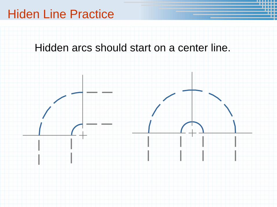
Hidden arcs should start on a center line.
Hiden Line Practice

Center Line Practice
In circular view, short dash should cross at the intersections of center
line.
For small hole, center line is presented as thin continuous line.
Center line should not extend between views.
Leave space
Leave space
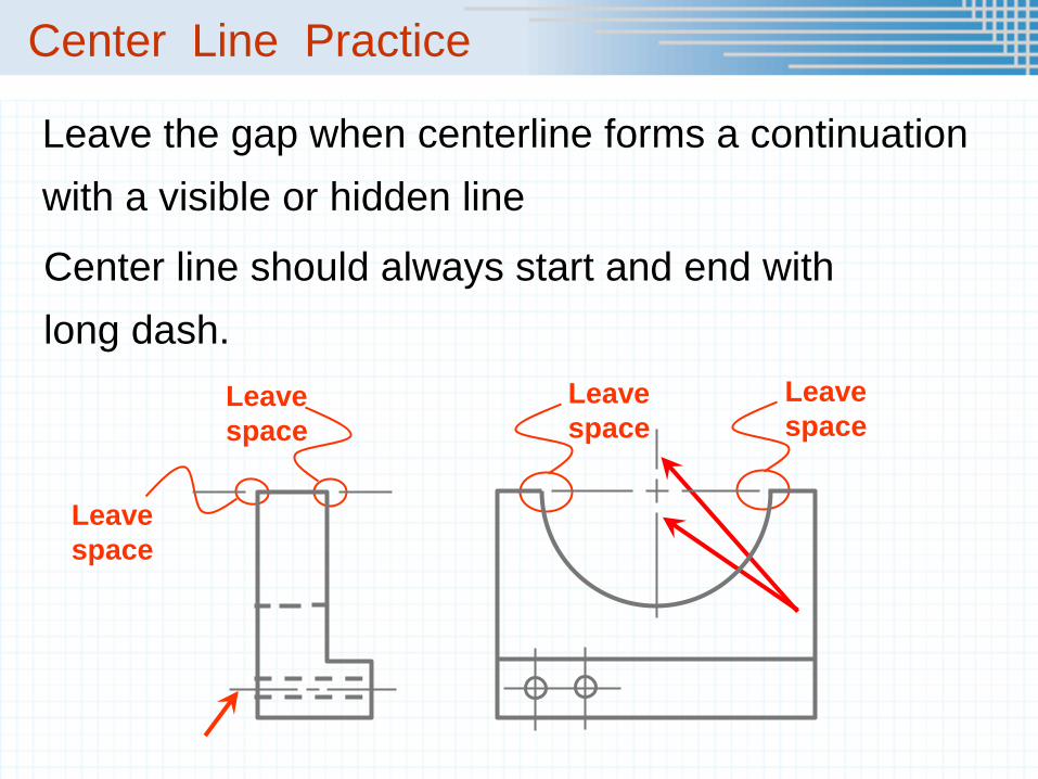
Leave the gap when centerline forms a continuation
with a visible or hidden line
Leave
space Leave
space Leave
space
Leave
space
Center line should always start and end with
long dash.
Center Line Practice

F
A
B C
F D E
G
A
B C
D
E F G
S
T
F

F
A
B
C
F
D
E
G
H I
A B
C
D
E
F
G
H I
S
T
F

F
A B
C
D
E A B
C
D E
S
T
F

F
A
H
S
T
F
A
B
C
D
B C D