Embed Size (px)
Citation preview
Engineering ManualVersion 4.0
1
Orkot® Marine BearingsEngineering Manual for Rudder and Water Lubricated Propeller Shaft Bearings
Contents
About this Manual . . . . . . . . . . . . . . . . . . . . . . . . . . . . . . . . . . . . . . . . . . . . . . . . .2
A Global Approach . . . . . . . . . . . . . . . . . . . . . . . . . . . . . . . . . . . . . . . . . . . . . . . .2
Orkot® Marine Bearings . . . . . . . . . . . . . . . . . . . . . . . . . . . . . . . . . . . . . . . . . . . . .2
Management Systems and Classification . . . . . . . . . . . . . . . . . . . . . . . . . . . . . . . .2
Material Properties . . . . . . . . . . . . . . . . . . . . . . . . . . . . . . . . . . . . . . . . . . . . . . . .3
Service and Support . . . . . . . . . . . . . . . . . . . . . . . . . . . . . . . . . . . . . . . . . . . . . . . .5
Web Site . . . . . . . . . . . . . . . . . . . . . . . . . . . . . . . . . . . . . . . . . . . . . . . . . . . . . . . . .5
World Wide Availability . . . . . . . . . . . . . . . . . . . . . . . . . . . . . . . . . . . . . . . . . . . . .5
Marine Stock Tube Sizes . . . . . . . . . . . . . . . . . . . . . . . . . . . . . . . . . . . . . . . . . . . .5
Standard Production Capacity Guidelines . . . . . . . . . . . . . . . . . . . . . . . . . . . . . . .6
Contact Details . . . . . . . . . . . . . . . . . . . . . . . . . . . . . . . . . . . . . . . . . . . . . . . . . . . .6
Rudder Bearings . . . . . . . . . . . . . . . . . . . . . . . . . . . . . . . . . . . . . . . . . . . . . . . . . .7
Bearing Design Pressure . . . . . . . . . . . . . . . . . . . . . . . . . . . . . . . . . . . . . . . . . . . .7
Material Selection . . . . . . . . . . . . . . . . . . . . . . . . . . . . . . . . . . . . . . . . . . . . . . . . .7
Lubrication . . . . . . . . . . . . . . . . . . . . . . . . . . . . . . . . . . . . . . . . . . . . . . . . . . . . . . .7
Housing and Shaft Requirements . . . . . . . . . . . . . . . . . . . . . . . . . . . . . . . . . . . . .7
Housing . . . . . . . . . . . . . . . . . . . . . . . . . . . . . . . . . . . . . . . . . . . . . . . . . . . . . . . . .7
Shaft . . . . . . . . . . . . . . . . . . . . . . . . . . . . . . . . . . . . . . . . . . . . . . . . . . . . . . . . . . .7
Design . . . . . . . . . . . . . . . . . . . . . . . . . . . . . . . . . . . . . . . . . . . . . . . . . . . . . . . . . .8
Wall Thickness . . . . . . . . . . . . . . . . . . . . . . . . . . . . . . . . . . . . . . . . . . . . . . . . . . . .8
Bearing Interference . . . . . . . . . . . . . . . . . . . . . . . . . . . . . . . . . . . . . . . . . . . . . . .8
Bearing Clearance . . . . . . . . . . . . . . . . . . . . . . . . . . . . . . . . . . . . . . . . . . . . . . . . .9
Machining Tolerance . . . . . . . . . . . . . . . . . . . . . . . . . . . . . . . . . . . . . . . . . . . . . . .9
Water Lubricated Stern Tube Bearings . . . . . . . . . . . . . . . . . . . . . . . . . . . . . . . .10
Bearing Design Pressure . . . . . . . . . . . . . . . . . . . . . . . . . . . . . . . . . . . . . . . . . . .10
Material Selection . . . . . . . . . . . . . . . . . . . . . . . . . . . . . . . . . . . . . . . . . . . . . . . .10
Shaft Requirements . . . . . . . . . . . . . . . . . . . . . . . . . . . . . . . . . . . . . . . . . . . . . . .10
Design . . . . . . . . . . . . . . . . . . . . . . . . . . . . . . . . . . . . . . . . . . . . . . . . . . . . . . . . .10
Multi Groove Bearing . . . . . . . . . . . . . . . . . . . . . . . . . . . . . . . . . . . . . . . . . . . . .10
Twin Groove Bearing . . . . . . . . . . . . . . . . . . . . . . . . . . . . . . . . . . . . . . . . . . . . . .10
Special Designs . . . . . . . . . . . . . . . . . . . . . . . . . . . . . . . . . . . . . . . . . . . . . . . . . . .10
Staves . . . . . . . . . . . . . . . . . . . . . . . . . . . . . . . . . . . . . . . . . . . . . . . . . . . . . . . . . .11
Water Flow Rate . . . . . . . . . . . . . . . . . . . . . . . . . . . . . . . . . . . . . . . . . . . . . . . . .11
Bearing Interference and Clearance . . . . . . . . . . . . . . . . . . . . . . . . . . . . . . . . . .12
Machining Tolerance . . . . . . . . . . . . . . . . . . . . . . . . . . . . . . . . . . . . . . . . . . . . . .13
Fitting Methods . . . . . . . . . . . . . . . . . . . . . . . . . . . . . . . . . . . . . . . . . . . . . . . . . .14
Bonding . . . . . . . . . . . . . . . . . . . . . . . . . . . . . . . . . . . . . . . . . . . . . . . . . . . . . . . .16
Machining Instructions . . . . . . . . . . . . . . . . . . . . . . . . . . . . . . . . . . . . . . . . . . . .17
Health and Safety Data . . . . . . . . . . . . . . . . . . . . . . . . . . . . . . . . . . . . . . . . . . . .19
Calculation Sheets . . . . . . . . . . . . . . . . . . . . . . . . . . . . . . . . . . . . . . . . . . . . . . . .23
2
Orkot® Marine BearingsEngineering Manual for Rudder and Water Lubricated Propeller Shaft Bearings
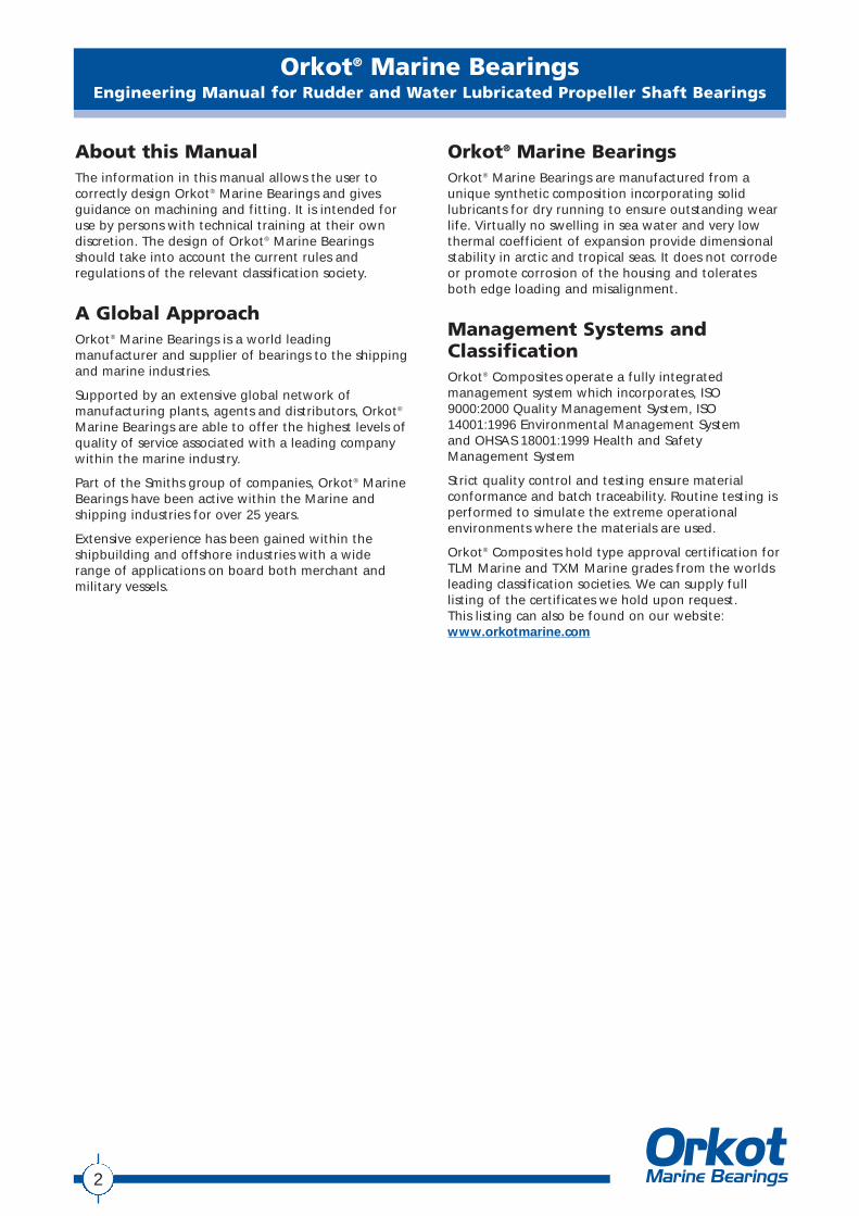
About this ManualThe information in this manual allows the user tocorrectly design Orkot® Marine Bearings and givesguidance on machining and fitting. It is intended foruse by persons with technical training at their owndiscretion. The design of Orkot® Marine Bearingsshould take into account the current rules andregulations of the relevant classification society.
A Global ApproachOrkot® Marine Bearings is a world leadingmanufacturer and supplier of bearings to the shippingand marine industries.
Supported by an extensive global network ofmanufacturing plants, agents and distributors, Orkot®
Marine Bearings are able to offer the highest levels ofquality of service associated with a leading companywithin the marine industry.
Part of the Smiths group of companies, Orkot® MarineBearings have been active within the Marine andshipping industries for over 25 years.
Extensive experience has been gained within theshipbuilding and offshore industries with a wide range of applications on board both merchant andmilitary vessels.
Orkot® Marine BearingsOrkot® Marine Bearings are manufactured from aunique synthetic composition incorporating solidlubricants for dry running to ensure outstanding wearlife. Virtually no swelling in sea water and very lowthermal coefficient of expansion provide dimensionalstability in arctic and tropical seas. It does not corrodeor promote corrosion of the housing and toleratesboth edge loading and misalignment.
Management Systems andClassificationOrkot® Composites operate a fully integratedmanagement system which incorporates, ISO9000:2000 Quality Management System, ISO14001:1996 Environmental Management System and OHSAS 18001:1999 Health and SafetyManagement System
Strict quality control and testing ensure materialconformance and batch traceability. Routine testing isperformed to simulate the extreme operationalenvironments where the materials are used.
Orkot® Composites hold type approval certification forTLM Marine and TXM Marine grades from the worldsleading classification societies. We can supply fulllisting of the certificates we hold upon request. This listing can also be found on our website:www.orkotmarine.com
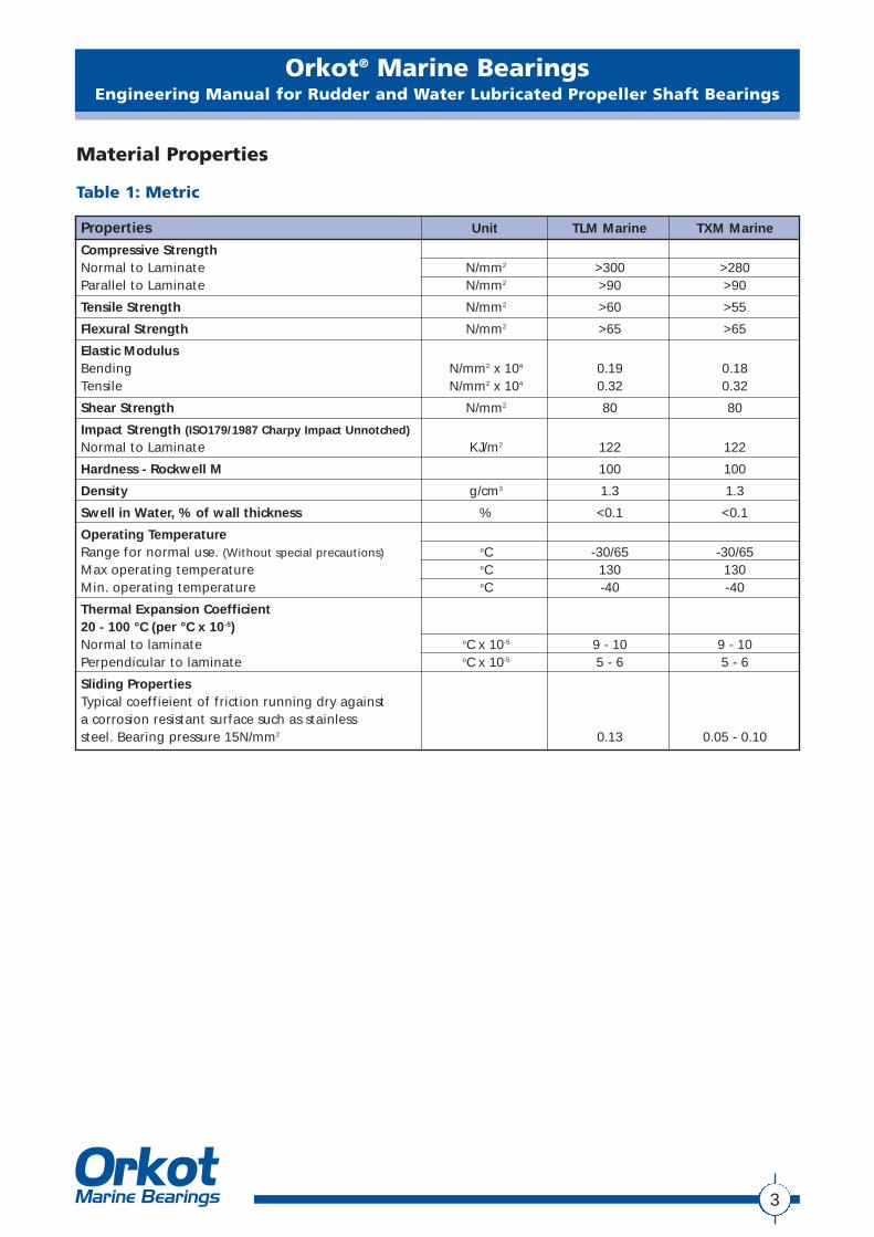
Properties Unit TLM Marine TXM Marine
Compressive StrengthNormal to Laminate N/mm2 >300 >280Parallel to Laminate N/mm2 >90 >90
Tensile Strength N/mm2 >60 >55
Flexural Strength N/mm2 >65 >65
Elastic ModulusBending N/mm2 x 104 0.19 0.18Tensile N/mm2 x 104 0.32 0.32
Shear Strength N/mm2 80 80
Impact Strength (ISO179/1987 Charpy Impact Unnotched)
Normal to Laminate KJ/m2 122 122
Hardness - Rockwell M 100 100
Density g/cm3 1.3 1.3
Swell in Water, % of wall thickness % <0.1 <0.1
Operating TemperatureRange for normal use. (Without special precautions) oC -30/65 -30/65Max operating temperature oC 130 130Min. operating temperature oC -40 -40
Thermal Expansion Coefficient20 - 100 °C (per °C x 10-5)Normal to laminate oC x 10-5 9 - 10 9 - 10Perpendicular to laminate oC x 10-5 5 - 6 5 - 6
Sliding PropertiesTypical coeffieient of friction running dry againsta corrosion resistant surface such as stainlesssteel. Bearing pressure 15N/mm2 0.13 0.05 - 0.10
3
Orkot® Marine BearingsEngineering Manual for Rudder and Water Lubricated Propeller Shaft Bearings
Material Properties
Table 1: Metric
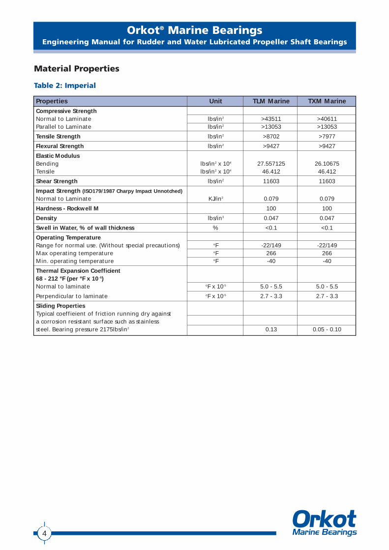
Properties Unit TLM Marine TXM Marine
Compressive StrengthNormal to Laminate lbs/in2 >43511 >40611Parallel to Laminate lbs/in2 >13053 >13053
Tensile Strength lbs/in2 >8702 >7977
Flexural Strength lbs/in2 >9427 >9427
Elastic ModulusBending lbs/in2 x 104 27.557125 26.10675Tensile lbs/in2 x 104 46.412 46.412
Shear Strength lbs/in2 11603 11603
Impact Strength (ISO179/1987 Charpy Impact Unnotched)
Normal to Laminate KJ/in2 0.079 0.079
Hardness - Rockwell M 100 100
Density lbs/in3 0.047 0.047
Swell in Water, % of wall thickness % <0.1 <0.1
Operating TemperatureRange for normal use. (Without special precautions) oF -22/149 -22/149Max operating temperature oF 266 266Min. operating temperature oF -40 -40
Thermal Expansion Coefficient68 - 212 °F (per °F x 10 -5)Normal to laminate oF x 10-5 5.0 - 5.5 5.0 - 5.5
Perpendicular to laminate oF x 10-5 2.7 - 3.3 2.7 - 3.3
Sliding PropertiesTypical coeffieient of friction running dry againsta corrosion resistant surface such as stainlesssteel. Bearing pressure 2175lbs/in2 0.13 0.05 - 0.10
4
Orkot® Marine BearingsEngineering Manual for Rudder and Water Lubricated Propeller Shaft Bearings
Material Properties
Table 2: Imperial
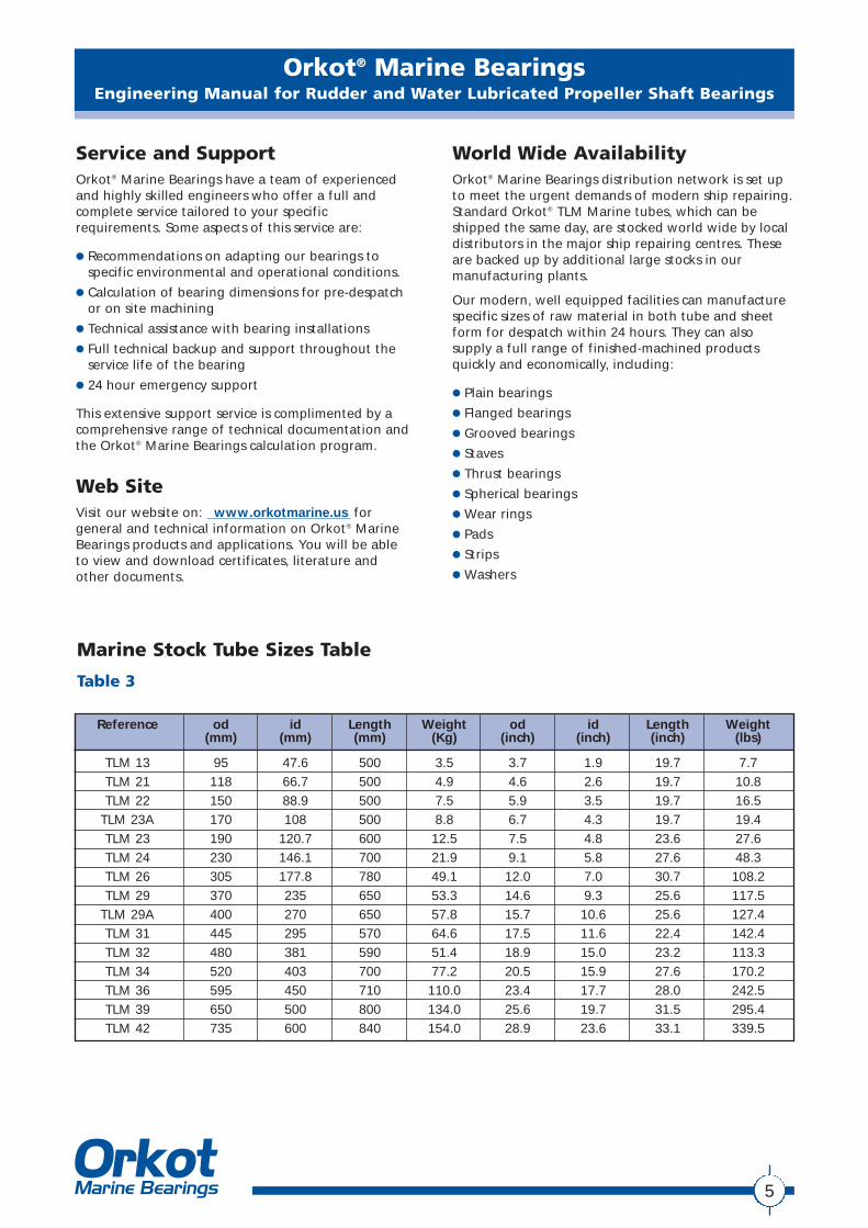
Reference od id Length Weight od id Length Weight(mm) (mm) (mm) (Kg) (inch) (inch) (inch) (lbs)
TLM 13 95 47.6 500 3.5 3.7 1.9 19.7 7.7TLM 21 118 66.7 500 4.9 4.6 2.6 19.7 10.8TLM 22 150 88.9 500 7.5 5.9 3.5 19.7 16.5
TLM 23A 170 108 500 8.8 6.7 4.3 19.7 19.4TLM 23 190 120.7 600 12.5 7.5 4.8 23.6 27.6TLM 24 230 146.1 700 21.9 9.1 5.8 27.6 48.3TLM 26 305 177.8 780 49.1 12.0 7.0 30.7 108.2TLM 29 370 235 650 53.3 14.6 9.3 25.6 117.5
TLM 29A 400 270 650 57.8 15.7 10.6 25.6 127.4TLM 31 445 295 570 64.6 17.5 11.6 22.4 142.4TLM 32 480 381 590 51.4 18.9 15.0 23.2 113.3TLM 34 520 403 700 77.2 20.5 15.9 27.6 170.2TLM 36 595 450 710 110.0 23.4 17.7 28.0 242.5TLM 39 650 500 800 134.0 25.6 19.7 31.5 295.4TLM 42 735 600 840 154.0 28.9 23.6 33.1 339.5
Service and SupportOrkot® Marine Bearings have a team of experiencedand highly skilled engineers who offer a full andcomplete service tailored to your specificrequirements. Some aspects of this service are:
● Recommendations on adapting our bearings tospecific environmental and operational conditions.
● Calculation of bearing dimensions for pre-despatchor on site machining
● Technical assistance with bearing installations
● Full technical backup and support throughout theservice life of the bearing
● 24 hour emergency support
This extensive support service is complimented by acomprehensive range of technical documentation andthe Orkot® Marine Bearings calculation program.
Web SiteVisit our website on: www.orkotmarine.us forgeneral and technical information on Orkot® MarineBearings products and applications. You will be able to view and download certificates, literature and other documents.
World Wide AvailabilityOrkot® Marine Bearings distribution network is set upto meet the urgent demands of modern ship repairing.Standard Orkot® TLM Marine tubes, which can beshipped the same day, are stocked world wide by localdistributors in the major ship repairing centres. Theseare backed up by additional large stocks in ourmanufacturing plants.
Our modern, well equipped facilities can manufacturespecific sizes of raw material in both tube and sheetform for despatch within 24 hours. They can alsosupply a full range of finished-machined productsquickly and economically, including:
● Plain bearings
● Flanged bearings
● Grooved bearings
● Staves
● Thrust bearings
● Spherical bearings
● Wear rings
● Pads
● Strips
● Washers
5
Orkot® Marine BearingsEngineering Manual for Rudder and Water Lubricated Propeller Shaft Bearings
Marine Stock Tube Sizes Table
Table 3
6
Orkot® Marine BearingsEngineering Manual for Rudder and Water Lubricated Propeller Shaft Bearings
Standard Production CapacityGuidelinesWith our current standard equipment and productionprocesses we are able to manufacture parts within the following guidelines. However we specialise inengineering solutions so please do not hesitate tocontact us if your requirements fall outside of these limits.
● Tube products up to 2500mm (98”) outside diameter and 1250mm (49”) long
● Sheets products up to 860mm (33”) wide and 3000mm (118”) long
● Rod products up to 200mm (8”) outside diameter and 500mm (19”) long
Contact DetailsPlease refer to our web site for the contact details of your local agent or distributor. Alternatively you can contact one of our manufacturing plants on the following:
Orkot® Marine Bearings, Rotherham, South Yorkshire, UK:
Phone: +44 1709 789828
Fax: +44 1709 789802
E-mail: [email protected]
24 hour emergency mobile phone: +44 1709 789840
Orkot® Marine Bearings, Eugene, Oregon, USA:
Phone: +1 541 688 5529
Fax: +1 541 688 2079
E-mail: [email protected]
24 hour emergency mobile phone +1 800 546 7568
Orkot® Marine BearingsEngineering Manual for Rudder and Water Lubricated Propeller Shaft Bearings
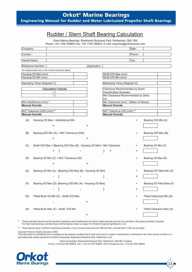
Rudder BearingsThis section provides general advice on rudder bearingdesign. It also provides the information required toallow the user to calculate the machining sizes of arudder bearing before and after fitting.
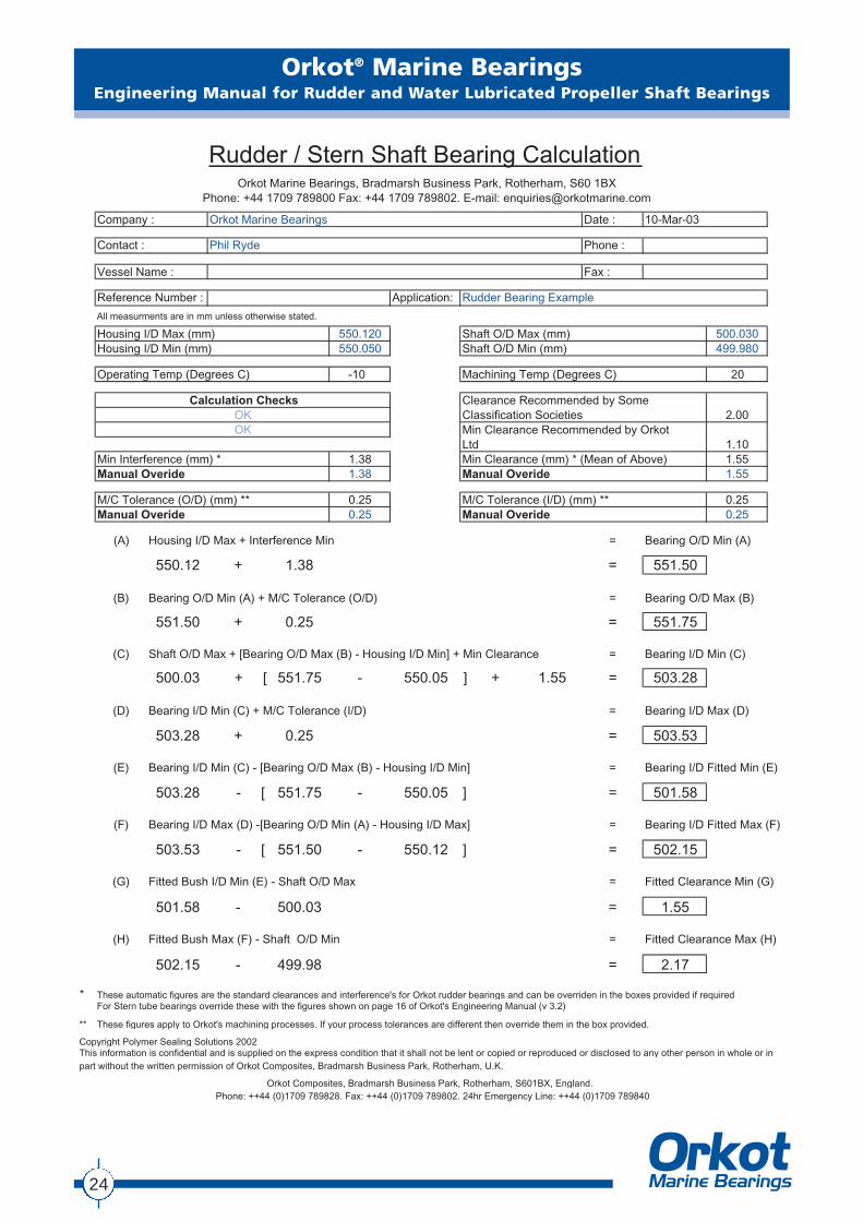
Page 24 shows a completed example of the Orkot®
Marine Bearings calculation for you to examine. Page 23 contains a blank for you to complete yourown calculation. Alternatively please feel free tocontact your local agent, distributor or manufacturingplant and we will be happy to advise you of themachining sizes.
A spreadsheet based calculation program is availableupon request.
Prior to carrying out any calculation, the followinginformation must be available:
● Minimum bearing operating temperature
● Approximate ambient temperature duringmachining
● Housing and shaft sizes with tolerances
Bearing Design Pressure
Orkot® TLM Marine has classification approval for up to15N/mm2 (2,176 lb/in2) in rudder bearing applications,while TXM Marine has approval for up to 10N/mm2
(1,450 lbs/in2). Clearly, this is linked to the applicationand the other components involved. When lookingonly at the properties of Orkot® Marine bearings muchhigher loads can be sustained. Orkot® Marine bearingsare in use in many other applications such as deckcranes, hatch cover slide pads, mooring systems andships stabilisers operating at bearing pressures rangingfrom 25 up to 100 N/mm2 (3,626 - 14,504 lb/in2).
Material Selection
Orkot® TLM Marine is the preferred material grade forrudder stock, pintle, neck and carrier bearings. Itincorporates solid lubricants which enable dry runningto ensure outstanding wear life for all rudder bushesoperating above or below the draft line. The materialwill operate without lubrication at pressures of 30N/mm2 (4,351 lb/in2) for short periods and has beentested at pressures of 14.5 N/mm2 (2,103 lb/in2) with avelocity of 1.3 m/min (4.3 ft/min) for 1.5 million cycleswith minimum lubrication.
Orkot® TXM Marine is a high performance materialwhich exhibits lower friction and wear properties thanour TLM Marine grade. It is approved to operatewithout lubrication in rudder bearing applications andhas been tested, with lubrication against stainless steelfor submarine steering gear at 57 N/mm2 (8,267 lb/in2)at 1 m/min (3.3 ft/min).
Lubrication
Water, grease or oil can provide bearing lubricationdepending on the application. No axial grooves arerequired with lubricated rudder bearings. Orkot® TLMMarine rudder bearings are capable of intermittentdry running against K-Monel®, Inconel® 625, Stellite®,duplex stainless and suitable corrosion resistantstainless steels.
7
Housing and Shaft Requirements
Housing
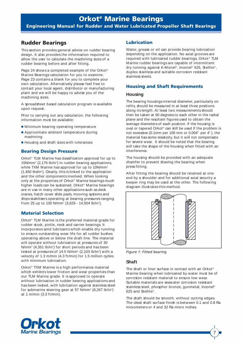
The bearing housings internal diameter, particularly onrefits, should be measured in at least three positionsalong its length. At least two measurements shouldthen be taken at 90 degrees to each other in the radialplane and the resultant figures used to obtain theaverage diameters of each position. If the housing isoval or tapered Orkot® can still be used if the problem isnot excessive (0.1mm per 100 mm or 0.004” per 4”), thematerial has some elasticity, but it will not compensatefor severe wear. It should be noted that the bearingwill take the shape of the housing when fitted with aninterference.
The housing should be provided with an adequatechamfer to prevent shaving the bearing when press fitting.
After fitting the bearing should be retained at oneend by a shoulder and for additional axial security akeeper ring may be used at the other. The followingdiagram illustrates this method.
Figure 1: Fitted bearing
Shaft
The shaft or liner surface in contact with an Orkot®
Marine bearing when lubricated by water must be ofcorrosion resistant material to ensure low wear.Suitable materials are seawater corrosion resistantstainless steel, phosphor bronze, gunmetal, Inconel®
625 and Stellite®.
The shaft should be smooth, without cutting edges.The ideal shaft surface finish is between 0.1 and 0.8 Ramicrometers or 4 and 32 Ra micro inches.
Orkot® Marine BearingsEngineering Manual for Rudder and Water Lubricated Propeller Shaft Bearings
Design
Wall Thickness
Normally in refits, the wall thickness of the bearing isfixed by the shaft and housing dimensions.
For new bearing designs the optimum wall thicknessshould be calculated as:
0.04 x shaft diameter plus 2 mm (0.08”).
Any bearing design with a wall thickness below thisvalue should always be checked by our engineeringdepartment to ensure it meets our minimumrequirements.
It should be noted that when an Orkot® Marinebearing of the optimum thickness is fitted into ahousing the interference is reflected as a reduction ofthe bearings internal diameter after fitting, i.e. thewall thickness before and after fitting will normallyremain constant. Bearings with thicker than optimumwalls may give less ”bore closure“.
Operating Value of "m"Temp Machining Temperature (°C)
(°C) 0 5 10 15 20 25 30
0 0.00131 0.00155 0.00178 0.00202 0.00225 0.00249 0.00273-10 0.00178 0.00202 0.00225 0.00249 0.00273 0.00296 0.00320-20 0.00229 0.00253 0.00277 0.00300 0.00324 0.00347 0.00371-30 0.00291 0.00311 0.00331 0.00351 0.00371 0.00391 0.00411
OperatingTemp Value
(°C) of "c"
0 -0.125-10 -0.125-20 -0.143-30 -0.158
Table 4 Table 5
Operating Value of "m"Temp Machining Temperature (°F)
(°F) 32 41 50 59 68 77 86
0 0.00131 0.00155 0.00178 0.00202 0.00225 0.00249 0.00273-10 0.00178 0.00202 0.00225 0.00249 0.00273 0.00296 0.00320-20 0.00229 0.00253 0.00277 0.00300 0.00324 0.00347 0.00371-30 0.00291 0.00311 0.00331 0.00351 0.00371 0.00391 0.00411
OperatingTemp Value
(°F) of "c"
32 -0.0049214 -0.00492-4 -0.00563
-22 -0.00622
Table 6 Table 7
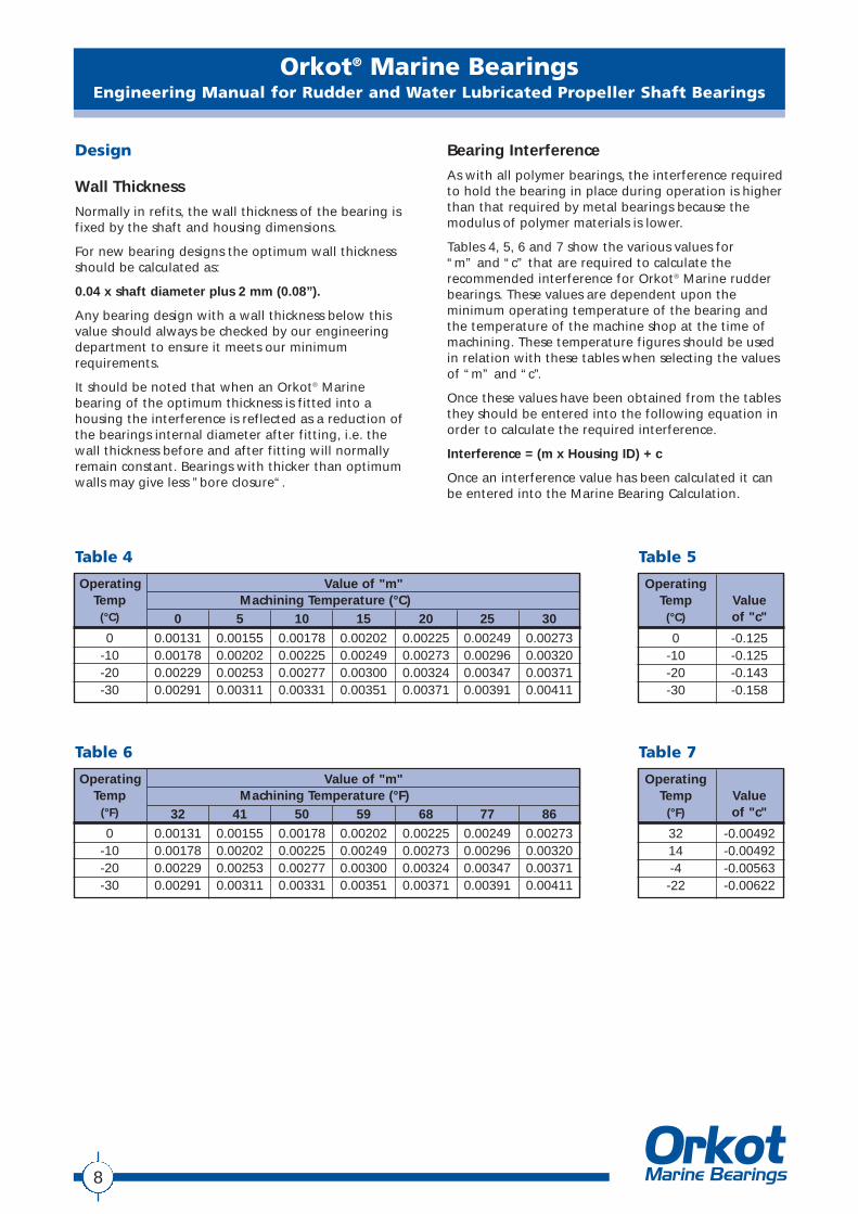
Bearing Interference
As with all polymer bearings, the interference requiredto hold the bearing in place during operation is higherthan that required by metal bearings because themodulus of polymer materials is lower.
Tables 4, 5, 6 and 7 show the various values for “m” and “c” that are required to calculate therecommended interference for Orkot® Marine rudderbearings. These values are dependent upon theminimum operating temperature of the bearing andthe temperature of the machine shop at the time ofmachining. These temperature figures should be usedin relation with these tables when selecting the valuesof “m” and “c”.
Once these values have been obtained from the tablesthey should be entered into the following equation inorder to calculate the required interference.
Interference = (m x Housing ID) + c
Once an interference value has been calculated it canbe entered into the Marine Bearing Calculation.
8
Orkot® Marine BearingsEngineering Manual for Rudder and Water Lubricated Propeller Shaft Bearings
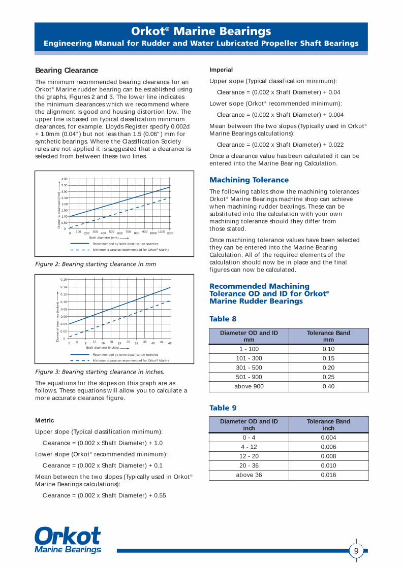
Bearing Clearance
The minimum recommended bearing clearance for anOrkot® Marine rudder bearing can be established usingthe graphs, Figures 2 and 3. The lower line indicatesthe minimum clearances which we recommend wherethe alignment is good and housing distortion low. Theupper line is based on typical classification minimumclearances, for example, Lloyds Register specify 0.002d+ 1.0mm (0.04") but not less than 1.5 (0.06") mm forsynthetic bearings. Where the Classification Societyrules are not applied it is suggested that a clearance isselected from between these two lines.
Figure 2: Bearing starting clearance in mm
Figure 3: Bearing starting clearance in inches.
The equations for the slopes on this graph are asfollows. These equations will allow you to calculate amore accurate clearance figure.
Metric
Upper slope (Typical classification minimum):
Clearance = (0.002 x Shaft Diameter) + 1.0
Lower slope (Orkot® recommended minimum):
Clearance = (0.002 x Shaft Diameter) + 0.1
Mean between the two slopes (Typically used in Orkot®
Marine Bearings calculations):
Clearance = (0.002 x Shaft Diameter) + 0.55
Imperial
Upper slope (Typical classification minimum):
Clearance = (0.002 x Shaft Diameter) + 0.04
Lower slope (Orkot® recommended minimum):
Clearance = (0.002 x Shaft Diameter) + 0.004
Mean between the two slopes (Typically used in Orkot®
Marine Bearings calculations):
Clearance = (0.002 x Shaft Diameter) + 0.022
Once a clearance value has been calculated it can beentered into the Marine Bearing Calculation.
Machining Tolerance
The following tables show the machining tolerancesOrkot® Marine Bearings machine shop can achievewhen machining rudder bearings. These can besubstituted into the calculation with your ownmachining tolerance should they differ from those stated.
Once machining tolerance values have been selectedthey can be entered into the Marine BearingCalculation. All of the required elements of thecalculation should now be in place and the finalfigures can now be calculated.
Recommended Machining Tolerance OD and ID for Orkot®
Marine Rudder Bearings
3.00
2.50
3.50
4.00
2.00
1.50
1.00
0.50
00 200 400 600 800100 300 500 700 900 1000 12001100
Recommended by some classification societies
Minimum clearance recommended for Orkot® Marine
Shaft diameter (mm)
Dia
met
ral c
lear
nac
e (m
m)
0.10
0.08
0.12
0.14
0.16
0.06
0.04
0.02
0
0 8 16 24 324 12 20 28 36 40 4844
Shaft diameter (inches)
Dia
met
ral c
lear
nac
e (i
nch
es)
Recommended by some classification societies
Minimum clearance recommended for Orkot® Marine
Diameter OD and IDmm
1 - 100
101 - 300
301 - 500
501 - 900
above 900
Tolerance Bandmm
0.10
0.15
0.20
0.25
0.40
Diameter OD and IDinch
0 - 4
4 - 12
12 - 20
20 - 36
above 36
Tolerance Bandinch
0.004
0.006
0.008
0.010
0.016
Table 8
Table 9
9
Water Lubricated Stern Tube BearingsThis section provides general advice on stern tubebearing design. It will also provide the informationrequired to allow the user to calculate a stern tubebearings dimensions before and after fitting.
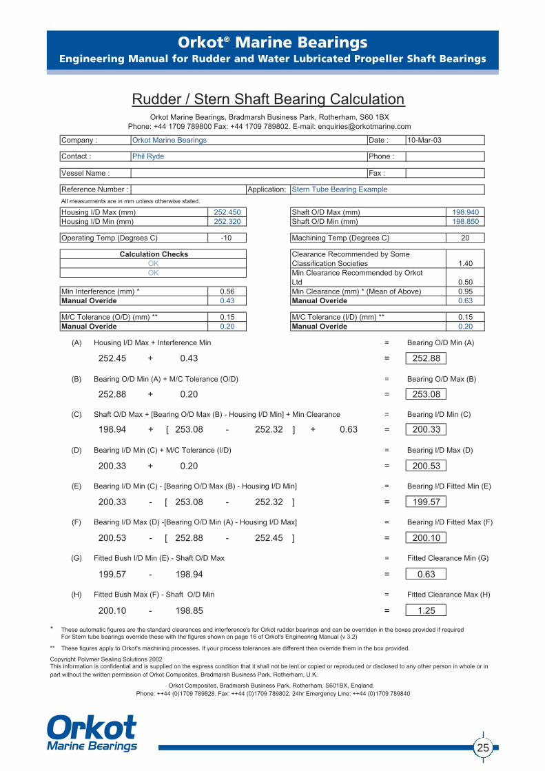
Page 25 shows a completed example of the Orkot®
Marine calculation for you to examine. Page 23contains a blank for you to complete your owncalculation. Alternatively please feel free to contactyour local agent, distributor or manufacturing plant and we will be happy to advise you of themachining sizes.
Prior to carrying out any calculation, the followinginformation must be available:
● Housing and shaft sizes with tolerances
Bearing Design Pressure
Water lubricated propeller shaft bearings need tooperate hydro-dynamically, i.e the shaft speed shouldbe sufficient to generate a water film to separate theshaft from the bearing. The design of these bearings isgoverned by the length to shaft diameter ratio whichcan vary from 4:1 to 2:1 depending on the bearingposition and upon approval from the classificationsocieties. Most classification societies apply a ratio of2:1 for Orkot® Marine grades. Full copies of thecertificates are available upon request or from ourweb site: www.orkotmarine.com
Material Selection
It should be noted that Orkot® materials are notsuitable for use in high speed grease or oil lubricatedstern shaft systems.
Orkot® TLM Marine is suitable for the majority ofwater lubricated stern tube systems.
Orkot® TXM Marine is especially suitable for low shaft velocities i.e. naval surface ship and submarinestern shafts.
Shaft Requirements
Orkot® Marine bearings can be used with mostrecognised shaft materials and is found to becompatible with gunmetal, phosphor bronze, Monel,Inconel® 625, 18/8 stainless steel.
If the bearing is subject to abrasive ingress,consideration should be given to the use of hardershaft liners or carbide coatings. Orkot® Marine tends toimprove the surface finish during running. As with allbearings subject to the ingress of abrasive particles,life can be reduced. For the stern tube bearings of avessel operating under such conditions a filtered watersupply is recommended.
A shaft surface finish of 0.8 micrometers or 32microinches Ra is required to reduce bedding in wear.
Design
A number of bearing designs can be manufacturedfrom Orkot® Marine grades for stern tube bearingapplications. The types in order of popularity are as follows:
Multi Groove Bearing
This conventional bearing design has equi-spaced axial grooves to allow water to circulate and cool thebearing and to enable debris to pass through withoutcausing damage to the shaft or bearing. This design is suitable for most vessels where shaft velocities arenot high.
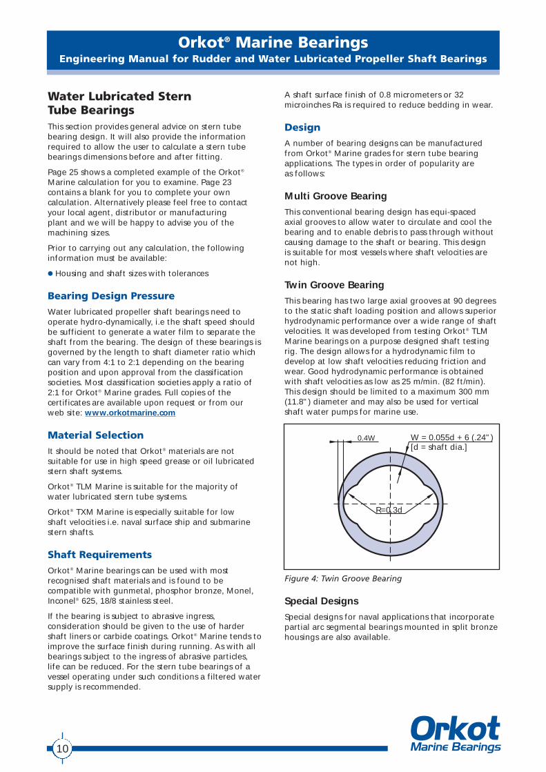
Twin Groove Bearing
This bearing has two large axial grooves at 90 degreesto the static shaft loading position and allows superiorhydrodynamic performance over a wide range of shaftvelocities. It was developed from testing Orkot® TLMMarine bearings on a purpose designed shaft testingrig. The design allows for a hydrodynamic film todevelop at low shaft velocities reducing friction andwear. Good hydrodynamic performance is obtainedwith shaft velocities as low as 25 m/min. (82 ft/min).This design should be limited to a maximum 300 mm(11.8") diameter and may also be used for verticalshaft water pumps for marine use.
Figure 4: Twin Groove Bearing
Special Designs
Special designs for naval applications that incorporatepartial arc segmental bearings mounted in split bronzehousings are also available.
Orkot® Marine BearingsEngineering Manual for Rudder and Water Lubricated Propeller Shaft Bearings
0.4W W = 0.055d + 6 (.24")[d = shaft dia.]
R=0.3d
10
Orkot® Marine BearingsEngineering Manual for Rudder and Water Lubricated Propeller Shaft Bearings
Staves
An alternative bearing design uses staves machinedfrom Orkot® TLM Marine sheet. It should be notedthat in refits the lignum vitae staves used in somevessels can be easily and more economically replacedwith Orkot® TLM Marine multi-groove bearings. Afterremoving the worn staves and keeper strips Orkot®
bushes can be machined to suit the bronze carrier inthe work shop or alternatively bored insitu.
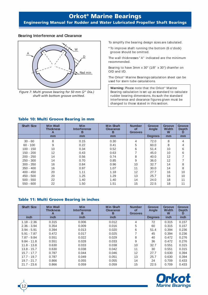
The length to a diameter ratio of an Orkot® Marinegrade stern tube bearing should be held to 2:1 ifpossible. Today the majority of classification societiesallow this as longer bearings increase the problem ofalignment. If classification rules require a longerbearings to be used it is suggested that the bearingclearance at the forward end for the additional length,above the 2:1 shaft to diameter ratio, should beincreased to provide a safety bearing. This can reducethe risk of misalignment and is illustrated in figure 6.
Water Flow Rate
A water flow rate of 0.18 litres per minute per mm ofshaft diameter is required or 1.21 US gallons per minper inch of shaft diameter.
Increased bearing diameter
The actual bearing should be positionedwhere the load is, hence at the propeller side
L=2D
D
Figure 6: Long bearing with increased clearance“safety bearing”
11
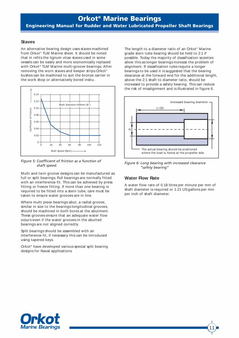
Figure 5: Coefficient of friction as a function of shaft speed.
Co
rffi
cien
t o
f fr
icti
on
Shaft Speed (Rpm)
Shaft diameter=200mm (8")
0.14
0.12
0.10
0.08
0.06
0.04
0.02
00 20 40 60 80 100 120
Multi and twin groove designs can be manufactured asfull or split bearings. Full bearings are normally fittedwith an interference fit. This can be achieved by pressfitting or freeze fitting. If more than one bearing isrequired to be fitted into a stern tube, care must betaken to ensure water grooves are in line.
Where multi piece bearings abut, a radial groove,similar in size to the bearings longitudinal grooves,should be machined in both bores at the abutment.These grooves ensure that an adequate water flowoccurs even if the water grooves in the abuttedbearings are not aligned correctly.
Split bearings should be assembled with aninterference fit, if necessary this can be introducedusing tapered keys.
Orkot® have developed various special split bearingdesigns for Naval applications.
Orkot® Marine BearingsEngineering Manual for Rudder and Water Lubricated Propeller Shaft Bearings
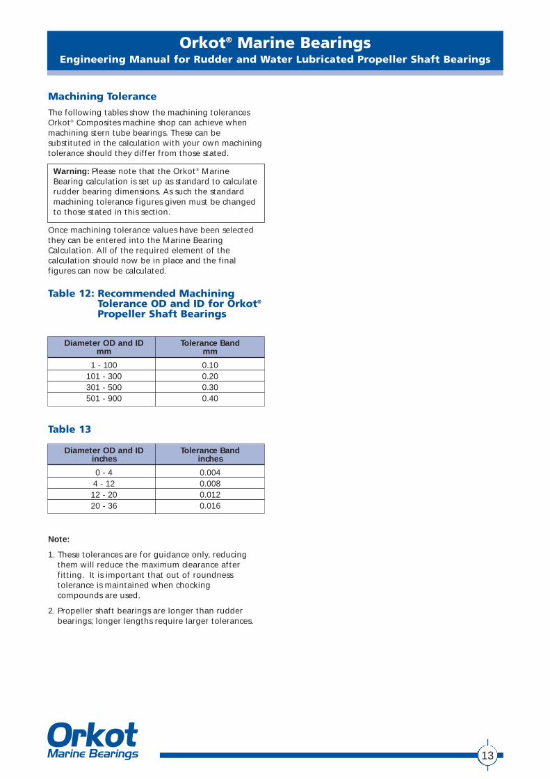
Table 10: Multi Groove Bearing in mm
Table 11: Multi Groove Bearing in inches
Shaft Size Min Wall Min Min Shaft Number Groove Groove GrooveThickness Interference Clearance of Angle Width Depth
A B B Grooves W Dmm mm mm Degrees mm mm
30 - 60 8 0.15 0.30 4 72.0 8 460 - 100 9 0.22 0.41 5 60.0 8 4100 - 150 10 0.34 0.52 6 51.4 10 6150 - 200 12 0.43 0.63 7 45.0 10 6200 - 250 14 0.56 0.74 8 40.0 12 7250 - 300 14 0.70 0.85 9 36.0 12 7300 - 350 16 0.84 0.96 10 32.7 14 8350 - 400 16 0.97 1.07 11 30.0 14 8400 - 450 20 1.11 1.18 12 27.7 16 10450 - 500 20 1.25 1.29 13 25.7 16 10500 - 550 22 1.40 1.40 14 24.0 18 11550 - 600 22 1.50 1.51 15 22.5 18 11
Shaft Size Min Wall Min Min Shaft Number Groove Groove GrooveThickness Interference Clearance of Angle Width Depth
A B B Grooves W Dinch inch inch inch Degrees inch inch
1.18 - 2.36 0.315 0.006 0.012 4 72 0.315 0.1572.36 - 3.94 0.354 0.009 0.016 5 60 0.315 0.1573.94 - 5.91 0.394 0.013 0.020 6 51.4 0.394 0.2365.91 - 7.87 0.472 0.017 0.025 7 45 0.394 0.2367.87 - 9.84 0.551 0.022 0.029 8 40 0.472 0.2769.84 - 11.8 0.551 0.028 0.033 9 36 0.472 0.27611.8 - 13.8 0.630 0.033 0.038 10 32.7 0.551 0.31513.8 - 15.7 0.630 0.038 0.042 11 30 0.551 0.31515.7 - 17.7 0.787 0.044 0.046 12 27.7 0.630 0.39417.7 - 19.7 0.787 0.049 0.051 13 25.7 0.630 0.39419.7 - 21.7 0.866 0.055 0.055 14 24 0.709 0.43321.7 - 23.6 0.866 0.059 0.059 15 22.5 0.709 0.433
Bearing Interference and Clearance
Figure 7: Multi groove bearing for 50 mm (2" Dia.)shaft with bottom groove omitted.
Rad min
D
WA
To simplify the bearing design sizes are tabulated.
*To improve shaft running the bottom (6 o'clock)groove should be omitted.
The wall thicknesses "A" indicated are the minimumrecommended.
Bearing to have 3mm x 30° (1/8" x 30°) chamfer onO/D and I/D.
The Orkot® Marine Bearings calculation sheet can beused for stern tube calculations.
Warning: Please note that the Orkot® MarineBearing calculation is set up as standard to calculaterudder bearing dimensions. As such the standardinterference and clearance figures given must bechanged to those stated in this section.
12
Orkot® Marine BearingsEngineering Manual for Rudder and Water Lubricated Propeller Shaft Bearings
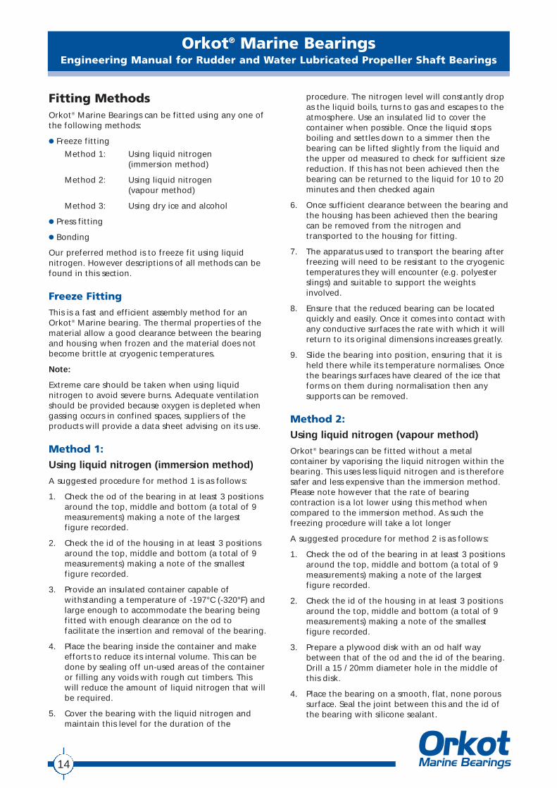
Machining Tolerance
The following tables show the machining tolerancesOrkot® Composites machine shop can achieve whenmachining stern tube bearings. These can besubstituted in the calculation with your own machiningtolerance should they differ from those stated.
Warning: Please note that the Orkot® MarineBearing calculation is set up as standard to calculaterudder bearing dimensions. As such the standardmachining tolerance figures given must be changedto those stated in this section.
Once machining tolerance values have been selectedthey can be entered into the Marine BearingCalculation. All of the required element of thecalculation should now be in place and the finalfigures can now be calculated.
Table 12: Recommended MachiningTolerance OD and ID for Orkot®
Propeller Shaft Bearings
Note:
1. These tolerances are for guidance only, reducingthem will reduce the maximum clearance afterfitting. It is important that out of roundnesstolerance is maintained when chocking compounds are used.
2. Propeller shaft bearings are longer than rudderbearings; longer lengths require larger tolerances.
Diameter OD and ID Tolerance Bandmm mm
1 - 100 0.10101 - 300 0.20301 - 500 0.30501 - 900 0.40
Diameter OD and ID Tolerance Bandinches inches
0 - 4 0.0044 - 12 0.00812 - 20 0.01220 - 36 0.016
Table 13
13
Fitting MethodsOrkot® Marine Bearings can be fitted using any one ofthe following methods:
● Freeze fitting
Method 1: Using liquid nitrogen (immersion method)
Method 2: Using liquid nitrogen (vapour method)
Method 3: Using dry ice and alcohol
● Press fitting
● Bonding
Our preferred method is to freeze fit using liquidnitrogen. However descriptions of all methods can befound in this section.
Freeze Fitting
This is a fast and efficient assembly method for anOrkot® Marine bearing. The thermal properties of thematerial allow a good clearance between the bearingand housing when frozen and the material does notbecome brittle at cryogenic temperatures.
Note:
Extreme care should be taken when using liquidnitrogen to avoid severe burns. Adequate ventilationshould be provided because oxygen is depleted whengassing occurs in confined spaces, suppliers of theproducts will provide a data sheet advising on its use.
Method 1:
Using liquid nitrogen (immersion method)
A suggested procedure for method 1 is as follows:
1. Check the od of the bearing in at least 3 positionsaround the top, middle and bottom (a total of 9measurements) making a note of the largest figure recorded.
2. Check the id of the housing in at least 3 positionsaround the top, middle and bottom (a total of 9measurements) making a note of the smallestfigure recorded.
3. Provide an insulated container capable ofwithstanding a temperature of -197°C (-320°F) andlarge enough to accommodate the bearing beingfitted with enough clearance on the od tofacilitate the insertion and removal of the bearing.
4. Place the bearing inside the container and makeefforts to reduce its internal volume. This can bedone by sealing off un-used areas of the containeror filling any voids with rough cut timbers. Thiswill reduce the amount of liquid nitrogen that willbe required.
5. Cover the bearing with the liquid nitrogen andmaintain this level for the duration of the
procedure. The nitrogen level will constantly dropas the liquid boils, turns to gas and escapes to theatmosphere. Use an insulated lid to cover thecontainer when possible. Once the liquid stopsboiling and settles down to a simmer then thebearing can be lifted slightly from the liquid andthe upper od measured to check for sufficient sizereduction. If this has not been achieved then thebearing can be returned to the liquid for 10 to 20minutes and then checked again
6. Once sufficient clearance between the bearing andthe housing has been achieved then the bearingcan be removed from the nitrogen andtransported to the housing for fitting.
7. The apparatus used to transport the bearing afterfreezing will need to be resistant to the cryogenictemperatures they will encounter (e.g. polyesterslings) and suitable to support the weightsinvolved.
8. Ensure that the reduced bearing can be locatedquickly and easily. Once it comes into contact withany conductive surfaces the rate with which it willreturn to its original dimensions increases greatly.
9. Slide the bearing into position, ensuring that it isheld there while its temperature normalises. Oncethe bearings surfaces have cleared of the ice thatforms on them during normalisation then anysupports can be removed.
Method 2:
Using liquid nitrogen (vapour method)
Orkot® bearings can be fitted without a metalcontainer by vaporising the liquid nitrogen within thebearing. This uses less liquid nitrogen and is thereforesafer and less expensive than the immersion method.Please note however that the rate of bearingcontraction is a lot lower using this method whencompared to the immersion method. As such thefreezing procedure will take a lot longer
A suggested procedure for method 2 is as follows:
1. Check the od of the bearing in at least 3 positionsaround the top, middle and bottom (a total of 9measurements) making a note of the largest figure recorded.
2. Check the id of the housing in at least 3 positionsaround the top, middle and bottom (a total of 9measurements) making a note of the smallestfigure recorded.
3. Prepare a plywood disk with an od half waybetween that of the od and the id of the bearing.Drill a 15 / 20mm diameter hole in the middle ofthis disk.
4. Place the bearing on a smooth, flat, none poroussurface. Seal the joint between this and the id ofthe bearing with silicone sealant.
Orkot® Marine BearingsEngineering Manual for Rudder and Water Lubricated Propeller Shaft Bearings
14
Orkot® Marine BearingsEngineering Manual for Rudder and Water Lubricated Propeller Shaft Bearings
5. Manufacture a simple lance from 10 mm (.40") orsimilar copper tube, drill approximately twenty 1mm (.40") diameter holes through both walls ofthe pipe and fit a bleed valve to the pipe to controlthe flow of liquid nitrogen. Ensure that you sealthe open end of the lancee.
6. Place the plywood disk on top of the bearing, and connect the lance to a pressurised liquidnitrogen tank.
7. Turn the valves to control the flow on nitrogenuntil vapour can be seen escaping, under pressurefrom the lance. If liquid starts to exit the lance thenthe flow should be reduced until it stops.
8. Place the lance though the hole in the centre ofthe disk and into the bearing. Wrap the bearing inan insulating blanket to reduce energy loss from itssurface.
9. During the procedure the nitrogen flow will need tobe monitored and adjusted from time to time.Measure the od at the top of the bearing periodically.
10. Once sufficient clearance between the bearing andthe housing has been achieved then the bearingcan be transported to the housing for fitting.
11. The apparatus used to transport the bearing afterfreezing will need to be resistant to the cryogenictemperatures they will encounter (e.g. polyesterslings) and suitable to support the weights involved.
12. Ensure that the reduced bearing can be locatedquickly and easily. Once it comes into contact withany conductive surfaces the rate with which it willreturn to its original dimensions increases greatly.
13. Slide the bearing into position, ensuring that it isheld there while its temperature normalises. Oncethe bearings surfaces have cleared of the ice thatforms on them during normalisation then anysupports can be removed.
Method 3:
Using dry ice and alcoholFreeze fitting using dry ice and alcohol will onlyprovide the required clearance when using very lightinterferences. As such it is rarely a viable method in itsown right and will often also require press fitting
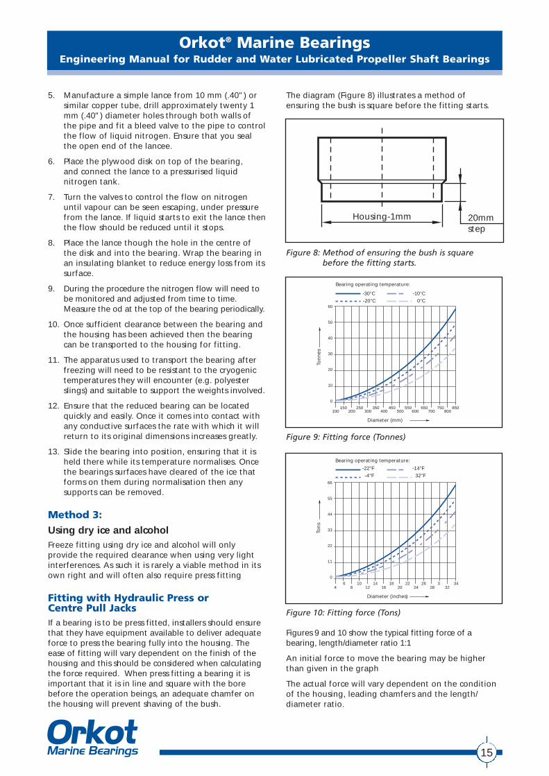
Fitting with Hydraulic Press or Centre Pull JacksIf a bearing is to be press fitted, installers should ensurethat they have equipment available to deliver adequateforce to press the bearing fully into the housing. Theease of fitting will vary dependent on the finish of thehousing and this should be considered when calculatingthe force required. When press fitting a bearing it isimportant that it is in line and square with the borebefore the operation beings, an adequate chamfer onthe housing will prevent shaving of the bush.
The diagram (Figure 8) illustrates a method ofensuring the bush is square before the fitting starts.
Figure 8: Method of ensuring the bush is squarebefore the fitting starts.
Housing-1mm 20mmstep
15
Ton
nes
Diameter (mm)
Bearing operating temperature:
-30°C -10°C-20°C 0°C
60
50
40
30
20
10
0
150 250 350 450 550 650 750 850100 200 300 400 500 600 700 800
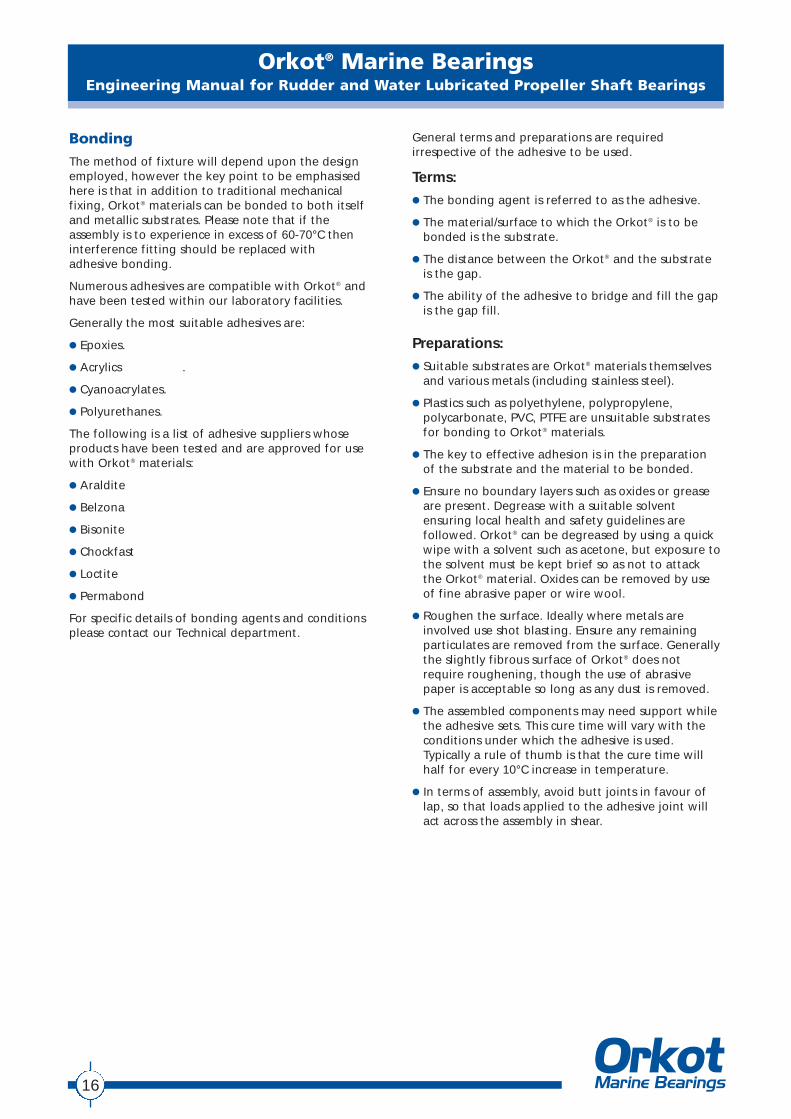
Figure 9: Fitting force (Tonnes)
Ton
s
Diameter (inches)
Bearing operating temperature:
-22°F -14°F-4°F 32°F
66
55
44
33
22
11
06 10 14 18 22 26 3 34
4 8 12 16 20 24 28 32
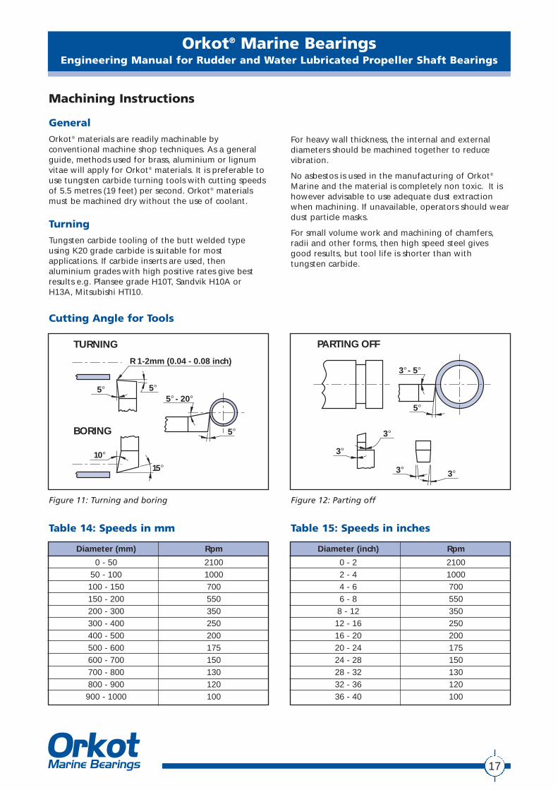
Figure 10: Fitting force (Tons)
Figures 9 and 10 show the typical fitting force of abearing, length/diameter ratio 1:1
An initial force to move the bearing may be higherthan given in the graph
The actual force will vary dependent on the conditionof the housing, leading chamfers and the length/diameter ratio.
Bonding
The method of fixture will depend upon the designemployed, however the key point to be emphasisedhere is that in addition to traditional mechanicalfixing, Orkot® materials can be bonded to both itselfand metallic substrates. Please note that if theassembly is to experience in excess of 60-70°C theninterference fitting should be replaced with adhesive bonding.
Numerous adhesives are compatible with Orkot® andhave been tested within our laboratory facilities.
Generally the most suitable adhesives are:
● Epoxies.
● Acrylics .
● Cyanoacrylates.
● Polyurethanes.
The following is a list of adhesive suppliers whoseproducts have been tested and are approved for usewith Orkot® materials:
● Araldite
● Belzona
● Bisonite
● Chockfast
● Loctite
● Permabond
For specific details of bonding agents and conditionsplease contact our Technical department.
General terms and preparations are requiredirrespective of the adhesive to be used.
Terms:● The bonding agent is referred to as the adhesive.
● The material/surface to which the Orkot® is to bebonded is the substrate.
● The distance between the Orkot® and the substrateis the gap.
● The ability of the adhesive to bridge and fill the gapis the gap fill.
Preparations:● Suitable substrates are Orkot® materials themselves
and various metals (including stainless steel).
● Plastics such as polyethylene, polypropylene,polycarbonate, PVC, PTFE are unsuitable substratesfor bonding to Orkot® materials.
● The key to effective adhesion is in the preparationof the substrate and the material to be bonded.
● Ensure no boundary layers such as oxides or greaseare present. Degrease with a suitable solventensuring local health and safety guidelines arefollowed. Orkot® can be degreased by using a quickwipe with a solvent such as acetone, but exposure tothe solvent must be kept brief so as not to attackthe Orkot® material. Oxides can be removed by useof fine abrasive paper or wire wool.
● Roughen the surface. Ideally where metals areinvolved use shot blasting. Ensure any remainingparticulates are removed from the surface. Generallythe slightly fibrous surface of Orkot® does notrequire roughening, though the use of abrasivepaper is acceptable so long as any dust is removed.
● The assembled components may need support whilethe adhesive sets. This cure time will vary with theconditions under which the adhesive is used.Typically a rule of thumb is that the cure time willhalf for every 10°C increase in temperature.
● In terms of assembly, avoid butt joints in favour oflap, so that loads applied to the adhesive joint willact across the assembly in shear.
Orkot® Marine BearingsEngineering Manual for Rudder and Water Lubricated Propeller Shaft Bearings
16
Orkot® Marine BearingsEngineering Manual for Rudder and Water Lubricated Propeller Shaft Bearings
17
Machining Instructions
General
Orkot® materials are readily machinable byconventional machine shop techniques. As a generalguide, methods used for brass, aluminium or lignumvitae will apply for Orkot® materials. It is preferable touse tungsten carbide turning tools with cutting speedsof 5.5 metres (19 feet) per second. Orkot® materialsmust be machined dry without the use of coolant.
Turning
Tungsten carbide tooling of the butt welded typeusing K20 grade carbide is suitable for mostapplications. If carbide inserts are used, thenaluminium grades with high positive rates give bestresults e.g. Plansee grade H10T, Sandvik H10A orH13A, Mitsubishi HTI10.
For heavy wall thickness, the internal and externaldiameters should be machined together to reducevibration.
No asbestos is used in the manufacturing of Orkot®
Marine and the material is completely non toxic. It ishowever advisable to use adequate dust extractionwhen machining. If unavailable, operators should weardust particle masks.
For small volume work and machining of chamfers,radii and other forms, then high speed steel givesgood results, but tool life is shorter than with tungsten carbide.
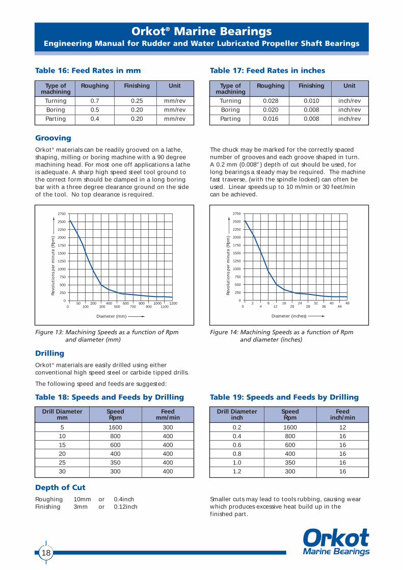
Cutting Angle for Tools
Figure 11: Turning and boring Figure 12: Parting off
5°
10°
15°
5°
5°
5° - 20°
R 1-2mm (0.04 - 0.08 inch)
TURNING
BORING
PARTING OFF
3° - 5°
5°
3°
3° 3°
3°
Diameter (mm) Rpm
0 - 50 210050 - 100 1000100 - 150 700150 - 200 550200 - 300 350300 - 400 250400 - 500 200500 - 600 175600 - 700 150700 - 800 130800 - 900 120900 - 1000 100
Diameter (inch) Rpm
0 - 2 21002 - 4 10004 - 6 7006 - 8 5508 - 12 350
12 - 16 25016 - 20 20020 - 24 17524 - 28 15028 - 32 13032 - 36 12036 - 40 100
Table 14: Speeds in mm Table 15: Speeds in inches
Orkot® Marine BearingsEngineering Manual for Rudder and Water Lubricated Propeller Shaft Bearings
18
Type of Roughing Finishing Unitmachining
Turning 0.7 0.25 mm/revBoring 0.5 0.20 mm/revParting 0.4 0.20 mm/rev
Type of Roughing Finishing Unitmachining
Turning 0.028 0.010 inch/revBoring 0.020 0.008 inch/revParting 0.016 0.008 inch/rev
Table 16: Feed Rates in mm Table 17: Feed Rates in inches
Grooving
Orkot® materials can be readily grooved on a lathe,shaping, milling or boring machine with a 90 degreemachining head. For most one off applications a latheis adequate. A sharp high speed steel tool ground tothe correct form should be clamped in a long boringbar with a three degree clearance ground on the sideof the tool. No top clearance is required.
The chuck may be marked for the correctly spacednumber of grooves and each groove shaped in turn. A 0.2 mm (0.008") depth of cut should be used, forlong bearings a steady may be required. The machinefast traverse, (with the spindle locked) can often beused. Linear speeds up to 10 m/min or 30 feet/min can be achieved.
Rev
olu
tio
ns
per
min
ute
(R
pm
)
Diameter (inches)
2750
2500
2250
2000
1750
1500
1250
1000
750
500
250
0
0 4 12 20 28 36 442 8 16 24 32 40 48
Rev
olu
tio
ns
per
min
ute
(R
pm
)
Diameter (mm)
2750
2500
2250
2000
1750
1500
1250
1000
750
500
250
0
0 100 300 500 700 900 110050 200 400 600 800 1000 1200
Figure 13: Machining Speeds as a function of Rpm and diameter (mm)
Figure 14: Machining Speeds as a function of Rpm and diameter (inches)
Drilling
Orkot® materials are easily drilled using eitherconventional high speed steel or carbide tipped drills.
The following speed and feeds are suggested:
Drill Diameter Speed Feedmm Rpm mm/min
5 1600 30010 800 40015 600 40020 400 40025 350 40030 300 400
Drill Diameter Speed Feedinch Rpm inch/min
0.2 1600 120.4 800 160.6 600 160.8 400 161.0 350 161.2 300 16
Table 18: Speeds and Feeds by Drilling Table 19: Speeds and Feeds by Drilling
Depth of Cut
Roughing 10mm or 0.4inchFinishing 3mm or 0.12inch
Smaller cuts may lead to tools rubbing, causing wearwhich produces excessive heat build up in the finished part.
Orkot® Marine BearingsEngineering Manual for Rudder and Water Lubricated Propeller Shaft Bearings
19
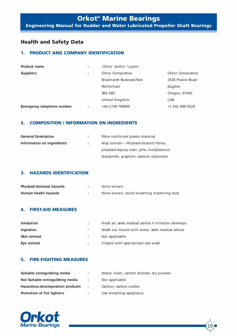
Health and Safety Data
1. PRODUCT AND COMPANY IDENTIFICATION
Product name : ‘Orkot’ and/or ‘Luytex’
Suppliers : Orkot Composites Orkot Composites
Bradmarsh Business Park 2535 Prairie Road
Rotherham Eugene
S60 1BX Oregon, 97402
United Kingdom USA
Emergency telephone number : +44 1709 789800 +1 541 688 5529
2. COMPOSITION / INFORMATION ON INGREDIENTS
General Description : Fibre reinforced plastic material
Information on ingredients : May contain – Polyester/aramid fibres,
polyester/epoxy resin, ptfe, molybdenum
disulphide, graphite, calcium carbonate
3. HAZARDS IDENTIFICATION
Physical/chemical hazards : None known
Human health hazards : None known, avoid breathing machining dust
4. FIRST-AID MEASURES
Inhalation : Fresh air, seek medical advice if irritation develops
Ingestion : Wash out mouth with water, seek medical advice
Skin contact : Not applicable
Eye contact : Irrigate with appropriate eye wash
5. FIRE-FIGHTING MEASURES
Suitable extinguishing media : Water, foam, carbon dioxide, dry powder
Not Suitable extinguishing media : Not applicable
Hazardous decomposition products : Carbon, carbon oxides
Protection of fire fighters : Use breathing apparatus
Orkot® Marine BearingsEngineering Manual for Rudder and Water Lubricated Propeller Shaft Bearings
20
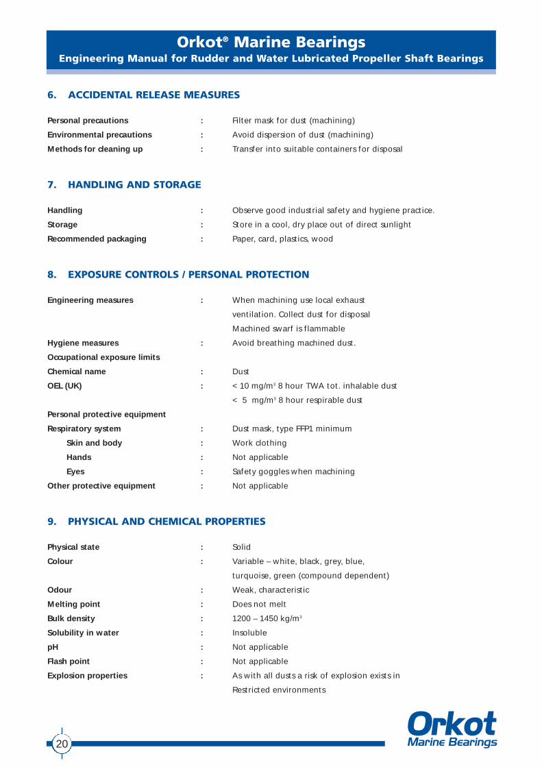
6. ACCIDENTAL RELEASE MEASURES
Personal precautions : Filter mask for dust (machining)
Environmental precautions : Avoid dispersion of dust (machining)
Methods for cleaning up : Transfer into suitable containers for disposal
7. HANDLING AND STORAGE
Handling : Observe good industrial safety and hygiene practice.
Storage : Store in a cool, dry place out of direct sunlight
Recommended packaging : Paper, card, plastics, wood
8. EXPOSURE CONTROLS / PERSONAL PROTECTION
Engineering measures : When machining use local exhaust
ventilation. Collect dust for disposal
Machined swarf is flammable
Hygiene measures : Avoid breathing machined dust.
Occupational exposure limits
Chemical name : Dust
OEL (UK) : < 10 mg/m3 8 hour TWA tot. inhalable dust
< 5 mg/m3 8 hour respirable dust
Personal protective equipment
Respiratory system : Dust mask, type FFP1 minimum
Skin and body : Work clothing
Hands : Not applicable
Eyes : Safety goggles when machining
Other protective equipment : Not applicable
9. PHYSICAL AND CHEMICAL PROPERTIES
Physical state : Solid
Colour : Variable – white, black, grey, blue,
turquoise, green (compound dependent)
Odour : Weak, characteristic
Melting point : Does not melt
Bulk density : 1200 – 1450 kg/m3
Solubility in water : Insoluble
pH : Not applicable
Flash point : Not applicable
Explosion properties : As with all dusts a risk of explosion exists in
Restricted environments
Orkot® Marine BearingsEngineering Manual for Rudder and Water Lubricated Propeller Shaft Bearings
21
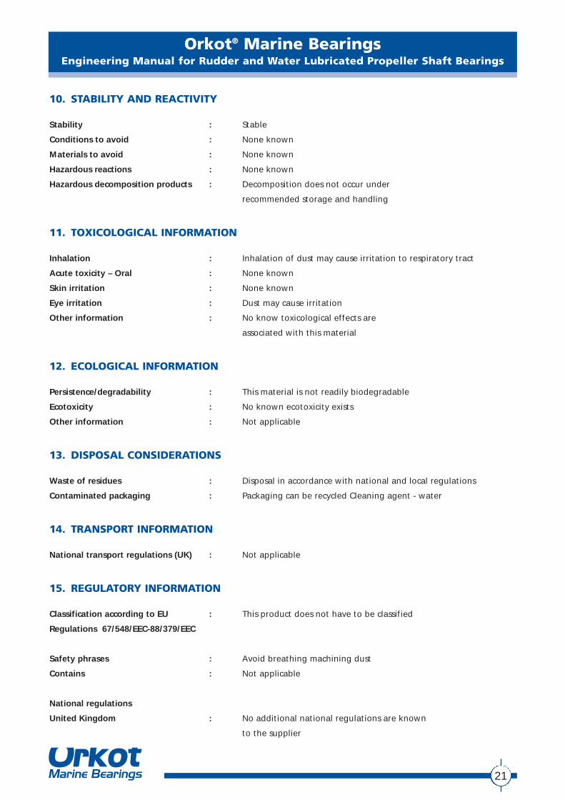
10. STABILITY AND REACTIVITY
Stability : Stable
Conditions to avoid : None known
Materials to avoid : None known
Hazardous reactions : None known
Hazardous decomposition products : Decomposition does not occur under
recommended storage and handling
11. TOXICOLOGICAL INFORMATION
Inhalation : Inhalation of dust may cause irritation to respiratory tract
Acute toxicity – Oral : None known
Skin irritation : None known
Eye irritation : Dust may cause irritation
Other information : No know toxicological effects are
associated with this material
12. ECOLOGICAL INFORMATION
Persistence/degradability : This material is not readily biodegradable
Ecotoxicity : No known ecotoxicity exists
Other information : Not applicable
13. DISPOSAL CONSIDERATIONS
Waste of residues : Disposal in accordance with national and local regulations
Contaminated packaging : Packaging can be recycled Cleaning agent - water
14. TRANSPORT INFORMATION
National transport regulations (UK) : Not applicable
15. REGULATORY INFORMATION
Classification according to EU : This product does not have to be classified
Regulations 67/548/EEC-88/379/EEC
Safety phrases : Avoid breathing machining dust
Contains : Not applicable
National regulations
United Kingdom : No additional national regulations are known
to the supplier
Orkot® Marine BearingsEngineering Manual for Rudder and Water Lubricated Propeller Shaft Bearings
22
16. OTHER INFORMATION
This safety data sheet is based on Orkot® Composites present knowledge and experience, and is intended to serveas a guide for safe handling of the product regarding to health and environmental aspects.
The information given in this data sheet was obtained from sources we believe are reliable. The information is,however, provided without any representation or warranty, expressed or implied, regarding its accuracy orcorrectness.
The conditions or methods of handling, storage, use and disposal of the product are beyond our control and maybe beyond our knowledge. For this, and other reasons, we do not assume responsibility and expressly disclaimliability for loss, damage or expense arising out of or in any way connected with the handling, storage, use ordisposal of the product.
Orkot® Marine BearingsEngineering Manual for Rudder and Water Lubricated Propeller Shaft Bearings
23
Rudder / Stern Shaft Bearing CalculationOrkot Marine Bearings, Bradmarsh Business Park, Rotherham, S60 1BX
Phone: +44 1709 789800 Fax: +44 1709 789802. E-mail: [email protected]
Company : Date :
Contact : Phone :
Vessel Name : Fax :
Reference Number : Application:
All measurments are in mm unless otherwise stated.
Housing I/D Max (mm) Shaft O/D Max (mm)Housing I/D Min (mm) Shaft O/D Min (mm)
Operating Temp (Degrees C) Machining Temp (Degrees C)
Calculation Checks Clearance Recommended by SomeOK Classification SocietiesOK Min Clearance Recommended by Orkot
LtdMin Interference (mm) * Min Clearance (mm) * (Mean of Above)Manual Overide Manual Overide
M/C Tolerance (O/D) (mm) ** M/C Tolerance (I/D) (mm) **Manual Overide Manual Overide
(A) Housing I/D Max + Interference Min = Bearing O/D Min (A)
+ =
(B) Bearing O/D Min (A) + M/C Tolerance (O/D) = Bearing O/D Max (B)
+ =
(C) Shaft O/D Max + [Bearing O/D Max (B) - Housing I/D Min] + Min Clearance = Bearing I/D Min (C)
+ [ - ] + =
(D) Bearing I/D Min (C) + M/C Tolerance (I/D) = Bearing I/D Max (D)
+ =
(E) Bearing I/D Min (C) - [Bearing O/D Max (B) - Housing I/D Min] = Bearing I/D Fitted Min (E)
- [ - ] =
(F) Bearing I/D Max (D) -[Bearing O/D Min (A) - Housing I/D Max] = Bearing I/D Fitted Max (F)
- [ - ] =
(G) Fitted Bush I/D Min (E) - Shaft O/D Max = Fitted Clearance Min (G)
- =
(H) Fitted Bush Max (F) - Shaft O/D Min = Fitted Clearance Max (H)
- =
* These automatic figures are the standard clearances and interference's for Orkot rudder bearings and can be overriden in the boxes provided if requiredFor Stern tube bearings override these with the figures shown on page 16 of Orkot's Engineering Manual (v 3.2)
** These figures apply to Orkot's machining processes. If your process tolerances are different then override them in the box provided.
Copyright Polymer Sealing Solutions 2002This information is confidential and is supplied on the express condition that it shall not be lent or copied or reproduced or disclosed to any other person in whole or inpart without the written permission of Orkot Composites, Bradmarsh Business Park, Rotherham, U.K.
Orkot Composites, Bradmarsh Business Park, Rotherham, S601BX, England. Phone: ++44 (0)1709 789828. Fax: ++44 (0)1709 789802. 24hr Emergency Line: ++44 (0)1709 789840
Orkot® Marine BearingsEngineering Manual for Rudder and Water Lubricated Propeller Shaft Bearings
24
Rudder / Stern Shaft Bearing CalculationOrkot Marine Bearings, Bradmarsh Business Park, Rotherham, S60 1BX
Phone: +44 1709 789800 Fax: +44 1709 789802. E-mail: [email protected]
Company : Orkot Marine Bearings Date : 10-Mar-03
Contact : Phil Ryde Phone :
Vessel Name : Fax :
Reference Number : Application: Rudder Bearing Example
All measurments are in mm unless otherwise stated.
Housing I/D Max (mm) 550.120 Shaft O/D Max (mm) 500.030Housing I/D Min (mm) 550.050 Shaft O/D Min (mm) 499.980
Operating Temp (Degrees C) -10 Machining Temp (Degrees C) 20
Calculation Checks Clearance Recommended by SomeOK Classification Societies 2.00OK Min Clearance Recommended by Orkot
Ltd 1.10Min Interference (mm) * 1.38 Min Clearance (mm) * (Mean of Above) 1.55Manual Overide 1.38 Manual Overide 1.55
M/C Tolerance (O/D) (mm) ** 0.25 M/C Tolerance (I/D) (mm) ** 0.25Manual Overide 0.25 Manual Overide 0.25
(A) Housing I/D Max + Interference Min = Bearing O/D Min (A)
550.12 + 1.38 = 551.50
(B) Bearing O/D Min (A) + M/C Tolerance (O/D) = Bearing O/D Max (B)
551.50 + 0.25 = 551.75
(C) Shaft O/D Max + [Bearing O/D Max (B) - Housing I/D Min] + Min Clearance = Bearing I/D Min (C)
500.03 + [ 551.75 - 550.05 ] + 1.55 = 503.28
(D) Bearing I/D Min (C) + M/C Tolerance (I/D) = Bearing I/D Max (D)
503.28 + 0.25 = 503.53
(E) Bearing I/D Min (C) - [Bearing O/D Max (B) - Housing I/D Min] = Bearing I/D Fitted Min (E)
503.28 - [ 551.75 - 550.05 ] = 501.58
(F) Bearing I/D Max (D) -[Bearing O/D Min (A) - Housing I/D Max] = Bearing I/D Fitted Max (F)
503.53 - [ 551.50 - 550.12 ] = 502.15
(G) Fitted Bush I/D Min (E) - Shaft O/D Max = Fitted Clearance Min (G)
501.58 - 500.03 = 1.55
(H) Fitted Bush Max (F) - Shaft O/D Min = Fitted Clearance Max (H)
502.15 - 499.98 = 2.17
* These automatic figures are the standard clearances and interference's for Orkot rudder bearings and can be overriden in the boxes provided if requiredFor Stern tube bearings override these with the figures shown on page 16 of Orkot's Engineering Manual (v 3.2)
** These figures apply to Orkot's machining processes. If your process tolerances are different then override them in the box provided.
Copyright Polymer Sealing Solutions 2002This information is confidential and is supplied on the express condition that it shall not be lent or copied or reproduced or disclosed to any other person in whole or inpart without the written permission of Orkot Composites, Bradmarsh Business Park, Rotherham, U.K.
Orkot Composites, Bradmarsh Business Park, Rotherham, S601BX, England. Phone: ++44 (0)1709 789828. Fax: ++44 (0)1709 789802. 24hr Emergency Line: ++44 (0)1709 789840
Orkot® Marine BearingsEngineering Manual for Rudder and Water Lubricated Propeller Shaft Bearings
25
Rudder / Stern Shaft Bearing CalculationOrkot Marine Bearings, Bradmarsh Business Park, Rotherham, S60 1BX
Phone: +44 1709 789800 Fax: +44 1709 789802. E-mail: [email protected]
Company : Orkot Marine Bearings Date : 10-Mar-03
Contact : Phil Ryde Phone :
Vessel Name : Fax :
Reference Number : Application: Stern Tube Bearing Example
All measurments are in mm unless otherwise stated.
Housing I/D Max (mm) 252.450 Shaft O/D Max (mm) 198.940Housing I/D Min (mm) 252.320 Shaft O/D Min (mm) 198.850
Operating Temp (Degrees C) -10 Machining Temp (Degrees C) 20
Calculation Checks Clearance Recommended by SomeOK Classification Societies 1.40OK Min Clearance Recommended by Orkot
Ltd 0.50Min Interference (mm) * 0.56 Min Clearance (mm) * (Mean of Above) 0.95Manual Overide 0.43 Manual Overide 0.63
M/C Tolerance (O/D) (mm) ** 0.15 M/C Tolerance (I/D) (mm) ** 0.15Manual Overide 0.20 Manual Overide 0.20
(A) Housing I/D Max + Interference Min = Bearing O/D Min (A)
252.45 + 0.43 = 252.88
(B) Bearing O/D Min (A) + M/C Tolerance (O/D) = Bearing O/D Max (B)
252.88 + 0.20 = 253.08
(C) Shaft O/D Max + [Bearing O/D Max (B) - Housing I/D Min] + Min Clearance = Bearing I/D Min (C)
198.94 + [ 253.08 - 252.32 ] + 0.63 = 200.33
(D) Bearing I/D Min (C) + M/C Tolerance (I/D) = Bearing I/D Max (D)
200.33 + 0.20 = 200.53
(E) Bearing I/D Min (C) - [Bearing O/D Max (B) - Housing I/D Min] = Bearing I/D Fitted Min (E)
200.33 - [ 253.08 - 252.32 ] = 199.57
(F) Bearing I/D Max (D) -[Bearing O/D Min (A) - Housing I/D Max] = Bearing I/D Fitted Max (F)
200.53 - [ 252.88 - 252.45 ] = 200.10
(G) Fitted Bush I/D Min (E) - Shaft O/D Max = Fitted Clearance Min (G)
199.57 - 198.94 = 0.63
(H) Fitted Bush Max (F) - Shaft O/D Min = Fitted Clearance Max (H)
200.10 - 198.85 = 1.25
* These automatic figures are the standard clearances and interference's for Orkot rudder bearings and can be overriden in the boxes provided if requiredFor Stern tube bearings override these with the figures shown on page 16 of Orkot's Engineering Manual (v 3.2)
** These figures apply to Orkot's machining processes. If your process tolerances are different then override them in the box provided.
Copyright Polymer Sealing Solutions 2002This information is confidential and is supplied on the express condition that it shall not be lent or copied or reproduced or disclosed to any other person in whole or inpart without the written permission of Orkot Composites, Bradmarsh Business Park, Rotherham, U.K.
Orkot Composites, Bradmarsh Business Park, Rotherham, S601BX, England. Phone: ++44 (0)1709 789828. Fax: ++44 (0)1709 789802. 24hr Emergency Line: ++44 (0)1709 789840
Orkot® Marine BearingsEngineering Manual for Rudder and Water Lubricated Propeller Shaft Bearings
26
This information in this manual is based on many years of experience in the manufacture and application of Orkot® Composites products.However, unknown parameters and conditions may restrict general statements during usage. It is vital that customers satisfy themselves as tothe suitability of individual products through adequate testing. For this reason, and due to the wide range of applications of our products,Smiths Group plc and Orkot® Composites can accept no liability as to the suitability or correctness of our general recommendations inindividual cases. For specific operating conditions please consult your Orkot® Composites Technical representative.
The application limits for pressure, temperature and speed given in this catalogue are maximum values determined in the laboratory. Duringpractical applications it should be remembered that due to the interaction of the operating parameters, the maximum values must be setcorrespondingly lower. For exceptional operating conditions, please contact us.
This edition supersedes all previous brochures.
© Smiths Group Plc / Orkot® Marine Bearings 2003. All rights reserved.This brochure, or any part thereof, may not be reproduced without our permission.
Non Smiths Group trade marks are referred to for technical advice only and do not express any preference to the use of these products. Thegenuine rights and liability of the owners of these trade marks are applicable.
Araldite® is a trade mark of Ciba-Geigy.Bisonite® is a trade mark of the Bolton Group.Belzona® is a trade mark of Belzona Molocular Ltd.Chockfast® is a trade mark of ITW Philadelphia Resins Corporation.Epocast® is a trade mark of Springer Marine+Industrial Services GmbHInconel® is a trade mark of INCO Alloys International, Inc.Loctite® is a trade mark of Loctite Corporation.Orkot® is a trade mark of Polymer Sealing Solutions Ltd.Permabond® a trade mark of Permabond Europe, a division of National Starch & Chemical.Stellite® is a trade mark of Deloro Stellite.

© Smiths Group Plc / Orkot Marine Bearings 2003. All rights reserved designed & produced by visualsource.co.uk
North & South AmericaOrkot Composites2535 Prairie RoadEugeneOregon, 97402USA
Tel: +1 (541) 688 5529Fax: +1 (541) 688 2079Email: [email protected] Hour Emergency Line: +1 (800) 546 7568
Europe, Africa, AsiaOrkot CompositesBradmarsh Business ParkRotherhamS60 1BX United Kingdom
Tel: +44 (0)1709 789 828Fax: +44 (0)1709 789 802Email: [email protected] Hour Emergency Line: +44 (0)1709 789 840
For further information visit: www.orkotmarine.us