Embed Size (px)
Citation preview
OrionLX
User Manual
May 6, 2014 Document Revision L © 2014 by NovaTech, LLC

OrionLX
ii
NovaTech, LLC 13555 West 107
th Street
Lenexa, KS 66215 Phone (913) 451-1880 www.novatechweb.com
[email protected] [email protected]
© Copyright 2009, 2014 by NovaTech, LLC
All Rights Reserved. All NovaTech trademarks are owned by NovaTech, LLC. All other trademarks are the property of their respective owners.
NCD may be installed on multiple computers as needed under the following conditions:
The computers must be owned by the end user or its subsidiary. The NCD installation must be used for an Orion-related project.
All files installed by NCD are protected by copyright and may not be shared with any third party. By installing NCD on a computer, you agree to these terms and conditions.
Disclaimer
This manual contains information that is correct to the best of NovaTech's knowledge. It is intended to be a guide and should be used as such. It should not be considered a sole source of technical instruction, replacing good technical judgment, since all possible situations cannot be anticipated. If there is any question as to the installation, configuration, or use of this product, contact NovaTech, LLC at (913) 451-1880. To ensure that the equipment described in this User's Manual, as well as all equipment connected to and used with it, operates in a satisfactory and safe manner, all applicable local and national codes that apply to installing and operating the equipment must be followed. Since these codes can vary geographically and can change with time, it is the user's responsibility to determine which codes and standards apply, and to comply with them.
Failure to follow the instructions provided in this manual, and/or failure to comply with applicable codes and safety standards can result in damage to this equipment, damage to connected devices, and/or serious injury to personnel.
All links to external websites have been verified as correct and appropriate at the time of the publication of this document. However, these links and websites, being outside of NovaTech LLC‟s control, are subject to change and may no longer be correct. In this case, please contact:
Authorized Representation – European Union
NovaTech Europe BVBA Kontichsesteenweg 71
2630 Aartselaar, Belgium Phone +32 (3) 458-0807
Fax +32 (3) 458-1817 General information: [email protected] Technical support: [email protected]
The CE version of this product is not available for purchase in Switzerland.
OrionLX
iii
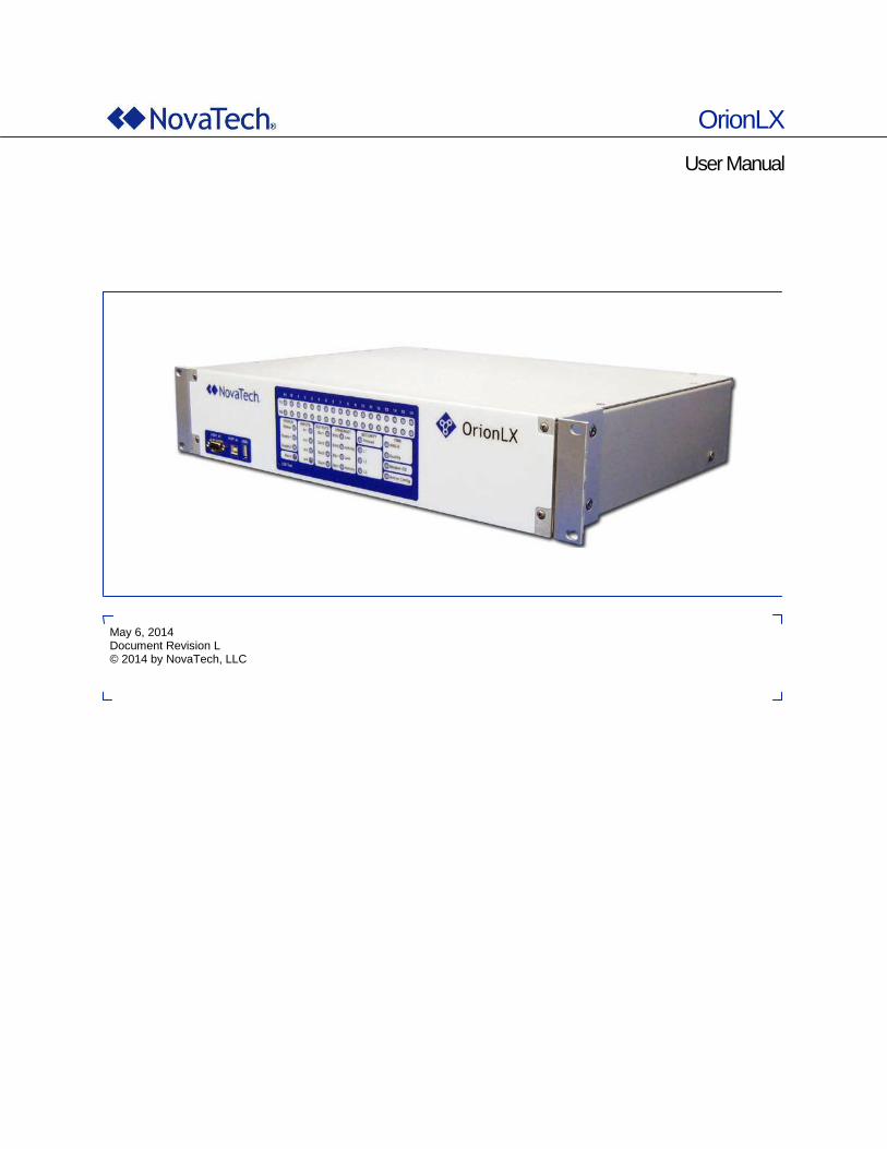
Styles and Symbols In this document, fonts, text styles and symbols are used to distinguish standard text from keyboard input, program text, GUI messages, and hyperlinks as follows. Warnings and safety notices are indicated with ANSI symbols.
Displayed text or symbol Description
This is normal text. Standard text
See OrionLX Setup Hyperlink to text in same document
www.novatechweb.com Hyperlink to website
[email protected] Clicking on this link starts email client on PC.
See OrionLX User Manual Document name
Minimum value Menu item or text displayed by software.
Name of the data point Text to be entered in input field or window.
Save GUI button to be clicked.
if frequency < 60.0 then Program code
<Enter>, <Ctrl>+<G>, <G> Key to be pressed
This yellow triangle indicates a warning that
must be observed by the users in order to
avoid possible equipment damage or
personal injury.
This yellow triangle indicates an electrical
hazard.
Electrostatic sensitive device requires proper
handling and grounding procedures to avoid
equipment damage.
DANGER indicates a hazardous situation
which, if not avoided, will result in death or
serious injury.
WARNING indicates a hazardous situation
which, if not avoided, could result in death or
serious injury.
CAUTION indicates a hazardous situation
which, if not avoided, may result in minor or
moderate injury.
Note that depending on the Windows® display settings on the computer running NCD, some of the screen shot details may appear differently than shown in this manual. The screen shots in this manual have been taken using the setting “Windows Classic” which is available on Windows XP®, Windows Vista® and Windows 7®.
OrionLX
iv
Table of Contents
A. Introduction ....................................................................................................................................... A-1
I. Introduction to OrionLX............................................................................................................. A-2
II. Overview of the OrionLX User Manual..................................................................................... A-3
III. Location of Documentation ...................................................................................................... A-4
IV. Setup of OrionLX ........................................................................................................................ A-5 1. Setup of OrionLX IP Address ............................................................................................. A-5 2. Setup using NCD ................................................................................................................. A-5 3. Setup using OrionLX Webpage .......................................................................................... A-6 4. Setup Worksheet ................................................................................................................. A-7 5. Change of Passwords ......................................................................................................... A-7
V. Operation of OrionLX ............................................................................................................... A-12
B. OrionLX Hardware ............................................................................................................................ B-1
I. Physical Specifications ............................................................................................................. B-2
II. OrionLX Options List ................................................................................................................. B-6 Part Number Example ................................................................................................................ B-8
III. OrionLX Front Panel .................................................................................................................. B-9 1. Diagnostic LED Description ............................................................................................... B-9 2. Port A1 Configuration and Diagnostic ............................................................................ B-12 3. Port A2 Configuration and Diagnostic ............................................................................ B-13 4. USB Ports ........................................................................................................................... B-14 5. LED Test ............................................................................................................................. B-14
IV. OrionLX Rear Panel ................................................................................................................. B-15 1. Power Connections ........................................................................................................... B-16 2. USB Ports ........................................................................................................................... B-17 3. Reset Button ...................................................................................................................... B-18 4. Port B .................................................................................................................................. B-18 5. Digital Inputs ...................................................................................................................... B-20
Wiring for Independent and Isolated Inputs ................................................................ B-21 Bussed Wiring for Common Wetting Voltage ............................................................. B-21
6. Digital Outputs ................................................................................................................... B-22 7. Ethernet Ports .................................................................................................................... B-23 8. Dial-up Modem Port ........................................................................................................... B-24 9. IRIG-B Port ......................................................................................................................... B-25 10. Ports 1-16 ........................................................................................................................... B-26
RS-232 Serial Card (Standard/Type –A and Isolated/Type –E Version) .................... B-27 Isolated RS-485/422 Serial Card (Type –B) .................................................................. B-30 ST Fiber Serial Card (Type –C) ..................................................................................... B-32 Isolated Bit Protocol Card (Type –D) ............................................................................ B-34 Isolated RS-485 Serial Card with IRIG-B (Type –G) .................................................... B-36 V-Pin HCS Fiber Serial Card (Type –H) ........................................................................ B-38
V. OrionLX Dimensioned Drawings ............................................................................................ B-39
VI. Mounting Instructions ............................................................................................................. B-40
VII. Fuse Replacement ................................................................................................................... B-41
OrionLX
v
1. Replacing Power Supply Surge Board Fuses ................................................................ B-41
C. NovaTech Configuration Director (NCD) ........................................................................................ C-1
I. Introduction to NovaTech Configuration Director (NCD) ....................................................... C-2 1. Purpose of NCD ................................................................................................................... C-2 2. System Requirements ......................................................................................................... C-3 3. Copyright Information ......................................................................................................... C-3 4. Outline of NCD Chapters .................................................................................................... C-3
II. Installation of NCD ..................................................................................................................... C-5
III. Running NCD .............................................................................................................................. C-8 1. Main Menu ............................................................................................................................ C-8 2. File Menu .............................................................................................................................. C-9 3. Edit Menu ............................................................................................................................ C-13
Updates Tab .................................................................................................................... C-14 General Tab ..................................................................................................................... C-14 Capture Tab .................................................................................................................... C-15
4. Configure Menu ................................................................................................................. C-17 Standard Software Features ......................................................................................... C-18 Operations in the Port Setup Windows ........................................................................ C-19 General ............................................................................................................................ C-20 Hardware Model Information ......................................................................................... C-21 Serial Ports ..................................................................................................................... C-22 Network ........................................................................................................................... C-24 NKI – Time Interface ....................................................................................................... C-26 Add Ons........................................................................................................................... C-29
Accumulator Freeze .............................................................................................. C-29 Alarm/Archive/Retentive ....................................................................................... C-29 Alias ........................................................................................................................ C-30 Data Logger ............................................................................................................ C-33 Orion LEDs ............................................................................................................. C-33 Points Blocking ...................................................................................................... C-34 Pseudo .................................................................................................................... C-34 Pusher ..................................................................................................................... C-34 System Logger ....................................................................................................... C-35 Text Module ............................................................................................................ C-35
Hardware I/O ................................................................................................................... C-35 Sensor ..................................................................................................................... C-36 SER .......................................................................................................................... C-43
Logic ................................................................................................................................ C-50 Math and Logic ....................................................................................................... C-50 Advanced Math and Logic .................................................................................... C-51 LogicPak ................................................................................................................. C-51 Distribution Automation (DA) ............................................................................... C-51 IEC 61131-3 ............................................................................................................. C-51
5. Communications Menu ..................................................................................................... C-52 Communication Window ............................................................................................... C-57
6. Window Menu..................................................................................................................... C-58 7. Help Menu ........................................................................................................................... C-59
Protocol Information ...................................................................................................... C-59 About ............................................................................................................................... C-60
D. OrionLX Webpage............................................................................................................................. D-1
I. Introduction ................................................................................................................................ D-2
OrionLX
vi
II. Home Tab .................................................................................................................................... D-6
III. DataValues Tab .......................................................................................................................... D-8 1. View Input Values ................................................................................................................ D-9
Toggle Options ............................................................................................................... D-10 2. Force Input Value .............................................................................................................. D-12 3. Viewing Output Values ...................................................................................................... D-14 4. Force Output Values ......................................................................................................... D-16
IV. Devices Tab .............................................................................................................................. D-18
V. Alarms Tab ................................................................................................................................ D-19
VI. Archive Tab ............................................................................................................................... D-21
VII. System Tab ............................................................................................................................... D-24
VIII. Logs Tab ................................................................................................................................... D-29
IX. Files Tab .................................................................................................................................... D-30 User Files .................................................................................................................................. D-30 Selecting the Active Configuration ........................................................................................ D-32 System Files ............................................................................................................................. D-33
X. Settings Tab .............................................................................................................................. D-34 1. Users ................................................................................................................................... D-36
Password Change .......................................................................................................... D-36 Account Management .................................................................................................... D-36
2. Authentication Rules ......................................................................................................... D-42 User Lockout Rules ........................................................................................................ D-42 Password Rules .............................................................................................................. D-43 Remote Root Login ........................................................................................................ D-44
3. Remote Accounts .............................................................................................................. D-45 Account Caching ............................................................................................................ D-48 Remote Accounts ........................................................................................................... D-49 Kerberos Authentication ............................................................................................... D-51
4. Firewall ............................................................................................................................... D-52 5. OpenVPN ............................................................................................................................ D-56 6. Key Management ............................................................................................................... D-59
Create Key ....................................................................................................................... D-61 7. System Log ........................................................................................................................ D-62 8. Networking ......................................................................................................................... D-64
Advanced Networking .................................................................................................... D-65 Common .......................................................................................................................... D-67 eth0, eth1, and eth2 ........................................................................................................ D-68
9. Modem ................................................................................................................................ D-69 Modem Initialization Strings.......................................................................................... D-72
10. System ................................................................................................................................ D-74 11. WebUI .................................................................................................................................. D-76
Login Message ............................................................................................................... D-77 Database ......................................................................................................................... D-77 Sessions .......................................................................................................................... D-77 HMI ................................................................................................................................... D-77 Web Files ......................................................................................................................... D-78 Link Bar ........................................................................................................................... D-79 Sections........................................................................................................................... D-81
12. Alarms ................................................................................................................................. D-83 Notifications .................................................................................................................... D-85 Colors .............................................................................................................................. D-85
OrionLX
vii
Alarm Archive ................................................................................................................. D-85 13. Database ............................................................................................................................. D-86 14. Tagging ............................................................................................................................... D-88 15. Cascading Slave ................................................................................................................ D-92 16. Services .............................................................................................................................. D-93 17. Scheduler ........................................................................................................................... D-94
Scheduling Tasks ........................................................................................................... D-95 Add CSV Task ................................................................................................................. D-98 Add FileMover Task ....................................................................................................... D-99
E. OrionLX MMI ...................................................................................................................................... E-1
I. Introduction ................................................................................................................................ E-2
II. Connecting to the Orion MMI .................................................................................................... E-3 1. OrionLX Port A ..................................................................................................................... E-3 2. Connecting to the OrionLX with NCD ................................................................................ E-3 3. Unlocking a User Account .................................................................................................. E-3
III. MMI Menus .................................................................................................................................. E-4 1. File Menu .............................................................................................................................. E-5
File Transfer (PC -> ORION) ............................................................................................ E-5 File Transfer (ORION -> PC) ............................................................................................ E-7 Make Config File Active ................................................................................................... E-8 Delete a File ...................................................................................................................... E-9 View a File ....................................................................................................................... E-10 Install downloaded packages ....................................................................................... E-11
2. Data Menu ........................................................................................................................... E-12 View Input Values ........................................................................................................... E-13 View Output Values ........................................................................................................ E-17 Override Input Values .................................................................................................... E-18 Clear Input Override ....................................................................................................... E-21 Send Output Values ....................................................................................................... E-22
3. View Communications ...................................................................................................... E-25 Master Port Troubleshooting ........................................................................................ E-28 Slave Port Troubleshooting .......................................................................................... E-29
4. Device Statistics ................................................................................................................ E-30 5. System Menu...................................................................................................................... E-31
Clock Configuration ....................................................................................................... E-32 View System Info ............................................................................................................ E-33 View Event Log ............................................................................................................... E-34 Clear Event Log .............................................................................................................. E-34 View Version Info ........................................................................................................... E-35 Passthrough Menu ......................................................................................................... E-36 Thread Info ...................................................................................................................... E-38 Restart ............................................................................................................................. E-40
6. Disconnect ......................................................................................................................... E-40 7. Session Timeouts .............................................................................................................. E-41 8. Network Menu .................................................................................................................... E-42
View/Change Network Configuration ........................................................................... E-43 Start/Stop Firewall .......................................................................................................... E-46
F. OrionLX Direct Video ....................................................................................................................... F-1
I. Introduction ................................................................................................................................. F-2
II. Connections ................................................................................................................................ F-4
III. OrionLX Video Port Setup .......................................................................................................... F-5
OrionLX
viii
IV. OrionLX Video Port Features ..................................................................................................... F-8 1. Operating Environment ........................................................................................................ F-8
Run Program ...................................................................................................................... F-9 Calibrate Touchscreen.................................................................................................... F-10 Calculator ......................................................................................................................... F-11 Text Editor ........................................................................................................................ F-11 Screenshot ....................................................................................................................... F-12 Terminal Emulator ........................................................................................................... F-13 File Manager .................................................................................................................... F-15 Document and Image Viewer ......................................................................................... F-15 Mixer ................................................................................................................................. F-16 Web Browser ................................................................................................................... F-18 Root Terminal .................................................................................................................. F-19 Network Analyzer ............................................................................................................ F-20 Desktop Settings ............................................................................................................. F-21 Toolbar Customization ................................................................................................... F-23
2. OrionLX Webpages ............................................................................................................ F-24 Setting Home Page in Midori Browser .......................................................................... F-25 Setting and Using Bookmarks ....................................................................................... F-27
G. Glossary ............................................................................................................................................ G-1
H. Additional Documentation ............................................................................................................... H-1
List of Figures
Figure A-1: Documentation in Windows XP ......................................................................................... A-4 Figure A-2: Documentation in Windows Vista and Windows 7 (classic view) ................................. A-4 Figure B-1: OrionLX Front Panel ........................................................................................................... B-9 Figure B-2: Port A1 Location ............................................................................................................... B-12 Figure B-3: Port A2 Location ............................................................................................................... B-13 Figure B-4: LED Test Button ................................................................................................................ B-14 Figure B-5: OrionLX Rear Panel .......................................................................................................... B-15 Figure B-6: OrionLX Power Connections ........................................................................................... B-16 Figure B-7: OrionLX Female and Male Power Connector Keyed for 12V dc ................................... B-16 Figure B-8: OrionLX Rear USB Ports .................................................................................................. B-17 Figure B-9: Reset Button ...................................................................................................................... B-18 Figure B-10: Port B ............................................................................................................................... B-18 Figure B-11: OrionLX Digital Input Connections ............................................................................... B-20 Figure B-12: Independent/Isolated Input Wiring ................................................................................ B-21 Figure B-13: Bussed Wiring for Common Wetting Voltage .............................................................. B-21 Figure B-14: OrionLX Digital Output Connections ............................................................................ B-22 Figure B-15: Output Wiring .................................................................................................................. B-22 Figure B-16: Dual Ethernet Ports ........................................................................................................ B-23 Figure B-17: Dual Ethernet/Fiber Port ................................................................................................. B-23 Figure B-18: Third Ethernet Port on Multimedia Board .................................................................... B-23 Figure B-19: OrionLX Modem Connection and Blank ....................................................................... B-24 Figure B-20: 1PPS and IRIG-B connections ....................................................................................... B-25 Figure B-21: Standard RS-232 Communication Card (Type –A) ...................................................... B-27 Figure B-22: Isolated RS-232 Communication Card (Type –E) ........................................................ B-27 Figure B-23: Standard RS-232 Mode (Default) ................................................................................... B-28
OrionLX
ix
Figure B-24: Isolated RS-485/422 Serial Card (Type –B) ................................................................... B-30 Figure B-25: ST Fiber Communication Card (–C) .............................................................................. B-32 Figure B-26: Isolated Bit Protocol Card (Type – D) ........................................................................... B-34 Figure B-27: Isolated Bit Protocol Card Front View .......................................................................... B-34 Figure B-28: Isolated RS-485 Communication Card with IRIG-B (-G) .............................................. B-36 Figure B-29: Termination Resistor Jumpers ...................................................................................... B-37 Figure B-30: V-Pin HCS Fiber Serial Card (Type –H) ......................................................................... B-38 Figure B-31: OrionLX Overall Dimensions and Panel Cutout .......................................................... B-39 Figure B-32: Mounted OrionLX ............................................................................................................ B-40 Figure B-33: Power Supply Board Fuses, Board Revisions B-D ..................................................... B-41 Figure B-34: Power Supply Board Fuse, Board Revision F and Newer .......................................... B-42 Figure C-1: Access to NCD and OrionLX Documentation in Windows
® XP...................................... C-4
Figure C-2: Access to NCD and OrionLX Documentation in Windows Vista® or Windows 7.0
® .... C-4
Figure C-3: NCD Installation .................................................................................................................. C-5 Figure C-4: Starting NCD Windows Vista
® or Windows 7.0
® .............................................................. C-5
Figure C-5: Starting NCD in Windows® XP ........................................................................................... C-6
Figure C-6: NCD Program Directory Structure..................................................................................... C-6 Figure C-7: NCD Data Directory Structure ............................................................................................ C-7 Figure C-8: NCD Main Menu ................................................................................................................... C-8 Figure C-9: File Menu .............................................................................................................................. C-9 Figure C-10: Selecting Configuration for Save, Save As, Close, Print .............................................. C-9 Figure C-11: Convert Operations ........................................................................................................ C-10 Figure C-12: Reorder Network Ports ................................................................................................... C-11 Figure C-13: Selection of Standard / Cascaded Configuration ........................................................ C-12 Figure C-14: NCD Prompt for Logic File ............................................................................................. C-12 Figure C-15: Edit Menu ......................................................................................................................... C-13 Figure C-16: User Settings – Updates Tab ......................................................................................... C-13 Figure C-17: User Settings – General Tab .......................................................................................... C-15 Figure C-18: User Settings – Capture Tab .......................................................................................... C-16 Figure C-19: Configure Menu ............................................................................................................... C-17 Figure C-20: Port Operations ............................................................................................................... C-19 Figure C-21: Choose port for protocol ................................................................................................ C-19 Figure C-22: General Settings.............................................................................................................. C-20 Figure C-23: OrionLX Hardware Configuration .................................................................................. C-21 Figure C-24: Port Selection .................................................................................................................. C-22 Figure C-25: Serial Protocol Selection Menu ..................................................................................... C-23 Figure C-26: Network Parameter and Port Configuration ................................................................. C-24 Figure C-27: Network Protocol Selection Menu ................................................................................. C-24 Figure C-28: NKI – Time Interface Setup ............................................................................................ C-26 Figure C-29: NKI – Port Setup .............................................................................................................. C-28 Figure C-30: Add On Options............................................................................................................... C-29 Figure C-31: Alias Assignment ............................................................................................................ C-30 Figure C-32: Using Reverse Point Name as Alias ............................................................................. C-32 Figure C-33: Example of Reverse Point Name Alias ......................................................................... C-33 Figure C-34: Orion LED Module ........................................................................................................... C-34 Figure C-35: Hardware I/O .................................................................................................................... C-35 Figure C-36: Sensor Setup - Port Tab ................................................................................................. C-36 Figure C-37: SER Setup - Devices ....................................................................................................... C-43 Figure C-38: SER Devices Drop-Down List ........................................................................................ C-44 Figure C-39: SER Setup – Port ............................................................................................................ C-44 Figure C-40: SER Setup – Inputs ......................................................................................................... C-45 Figure C-41: SER Setup – Outputs ...................................................................................................... C-47 Figure C-42: Logic Options .................................................................................................................. C-50 Figure C-43: NCD Communications .................................................................................................... C-52 Figure C-44: Manage Connections ...................................................................................................... C-53
OrionLX
x
Figure C-45: Saving/Loading Connection Files ................................................................................. C-54 Figure C-46: Connection Information ................................................................................................. C-55 Figure C-47: NCD Comm Window ....................................................................................................... C-57 Figure C-48: Window Menu .................................................................................................................. C-58 Figure C-49: Help Menu ........................................................................................................................ C-59 Figure C-50: Protocol Information ....................................................................................................... C-59 Figure C-51: NCD Version Information ............................................................................................... C-60 Figure D-1: Connect with OrionLX ........................................................................................................ D-2 Figure D-2: Internet Explorer Security Warning .................................................................................. D-2 Figure D-3: Firefox Security Warning ................................................................................................... D-3 Figure D-4: Confirm Firefox Certificate ................................................................................................. D-3 Figure D-5: OrionLX Login ..................................................................................................................... D-4 Figure D-6: OrionLX Homepage ............................................................................................................ D-4 Figure D-7: OrionLX Unlock Prompt ..................................................................................................... D-5 Figure D-8: OrionLX Home Tab ............................................................................................................. D-6 Figure D-9: DataValues – Main Page ..................................................................................................... D-8 Figure D-10: DataValues – View Input Values ...................................................................................... D-9 Figure D-11: DataValues – Toggle Options ........................................................................................ D-10 Figure D-12: DataValues – Force Input Value .................................................................................... D-12 Figure D-13: DataValues – Select Output Values .............................................................................. D-14 Figure D-14: DataValues – View Output Values ................................................................................. D-15 Figure D-15: DataValues – Force Output Value ................................................................................. D-16 Figure D-16: Devices Page ................................................................................................................... D-18 Figure D-17: Alarms Tab ....................................................................................................................... D-19 Figure D-18: Alarm Archive with Filter ................................................................................................ D-19 Figure D-19: Alarm Archive without Filter .......................................................................................... D-20 Figure D-20: Archive - 1000 Most Recent Records ............................................................................ D-21 Figure D-21: Archive with Custom Filter ............................................................................................ D-22 Figure D-22: Archive – View Trending ................................................................................................ D-23 Figure D-23: Archive – Trend for Multiple Data Points ..................................................................... D-23 Figure D-24: System Page .................................................................................................................... D-24 Figure D-25: System Page .................................................................................................................... D-25 Figure D-26: System Page .................................................................................................................... D-26 Figure D-27: System Page .................................................................................................................... D-27 Figure D-28: System Page .................................................................................................................... D-27 Figure D-29: Log Page .......................................................................................................................... D-29 Figure D-30: Files Page ........................................................................................................................ D-30 Figure D-31: Send Files to OrionLX .................................................................................................... D-31 Figure D-32: Select Active Configuration ........................................................................................... D-32 Figure D-33: Confirmation Prompt ...................................................................................................... D-32 Figure D-34: System Files .................................................................................................................... D-33 Figure D-35: Settings Page .................................................................................................................. D-34 Figure D-36: Change User Password .................................................................................................. D-36 Figure D-37: Settings/Users ................................................................................................................. D-37 Figure D-38: User Account Management ............................................................................................ D-39 Figure D-39: Authentication Rules – User Lockout Rules ................................................................ D-42 Figure D-40: Authentication Rules – Password Rules ...................................................................... D-43 Figure D-41: Authentication Rules – Remote Root Login ................................................................. D-44 Figure D-42: SSSD Package is Installed ............................................................................................. D-45 Figure D-43: Verification of Available File System Space ................................................................ D-45 Figure D-44: Remote Accounts ........................................................................................................... D-47 Figure D-45: Firewall Settings.............................................................................................................. D-52 Figure D-46: Firewall Filter Options .................................................................................................... D-53 Figure D-47: OpenVPN Settings .......................................................................................................... D-56 Figure D-48: Key Management Settings ............................................................................................. D-59
OrionLX
xi
Figure D-49: Default Key Values .......................................................................................................... D-60 Figure D-50: Create New Key ............................................................................................................... D-61 Figure D-51: System Log Setup ........................................................................................................... D-62 Figure D-52: Networking Settings ....................................................................................................... D-65 Figure D-53: Static Route Configuration ............................................................................................ D-66 Figure D-54: Internal Modem Settings ................................................................................................ D-69 Figure D-55: External Modem Settings ............................................................................................... D-70 Figure D-56: System Settings .............................................................................................................. D-74 Figure D-57: WebUI Setup .................................................................................................................... D-76 Figure D-58: Custom Login Message .................................................................................................. D-77 Figure D-59: Small Text in Header and Link Bar ................................................................................ D-78 Figure D-60: Large Text in Header and Link Bar ............................................................................... D-78 Figure D-61: Control Dialog with Tag Information ............................................................................. D-78 Figure D-62: Control Dialog without Tag Information ....................................................................... D-78 Figure D-63: Set Link to User-defined .svg File ................................................................................. D-79 Figure D-64: Link to User-defined .svg File ........................................................................................ D-79 Figure D-65: Link Bar Example ............................................................................................................ D-79 Figure D-66: Link Bar Setup ................................................................................................................. D-80 Figure D-67: Webpage Access Security and Display Options ......................................................... D-81 Figure D-68: Link Bar and Header Settings ........................................................................................ D-82 Figure D-69: Alarm Archive Settings .................................................................................................. D-84 Figure D-70: Database Settings ........................................................................................................... D-86 Figure D-71: Add Database User ......................................................................................................... D-87 Figure D-72: Tag List ............................................................................................................................ D-88 Figure D-73: Add New Tag ................................................................................................................... D-89 Figure D-74: Tagging Button in Graphics ........................................................................................... D-90 Figure D-75: Setting a Standard Tag ................................................................................................... D-91 Figure D-76: Setting a Custom Tag ..................................................................................................... D-91 Figure D-77: Cascading Slave ............................................................................................................. D-92 Figure D-78: Services Settings ............................................................................................................ D-93 Figure D-79: Scheduler – Task List ..................................................................................................... D-94 Figure D-80: Task Scheduling.............................................................................................................. D-95 Figure D-81: Task Example – Daily at 00:05 ....................................................................................... D-97 Figure D-82: Task Example – Every Three Hours .............................................................................. D-97 Figure D-83: Task List Example ........................................................................................................... D-97 Figure D-84: CSV Task Parameters ..................................................................................................... D-98 Figure D-85: FileMover Task Parameters ........................................................................................... D-99 Figure E-1: OrionLX MMI Main Menu .................................................................................................... E-4 Figure E-2: OrionLX File Menu .............................................................................................................. E-5 Figure E-3: File Transfer to OrionLX using NCD ................................................................................. E-6 Figure E-4: File Transfer to OrionLX using terminal software ........................................................... E-6 Figure E-5: File Transfer OrionLX to PC ............................................................................................... E-7 Figure E-6: File Transfer to PC using terminal software ..................................................................... E-8 Figure E-7: Configuration File Selection .............................................................................................. E-8 Figure E-8: Make Selected Configuration File Active .......................................................................... E-9 Figure E-9: Delete File from Flash Memory .......................................................................................... E-9 Figure E-10: Select File for Viewing .................................................................................................... E-10 Figure E-11: View File ........................................................................................................................... E-11 Figure E-12: Package Menu ................................................................................................................. E-11 Figure E-13: Data Menu ........................................................................................................................ E-12 Figure E-14: Select Port for Input Point Monitoring .......................................................................... E-13 Figure E-15: Input Point Monitoring .................................................................................................... E-14 Figure E-16: Data View Column Editor ............................................................................................... E-15 Figure E-17: Data View Sort Editor ...................................................................................................... E-16 Figure E-18: Select Port for Output Monitoring ................................................................................. E-17
OrionLX
xii
Figure E-19: Output Point Monitoring ................................................................................................. E-17 Figure E-20: Select Port for Forcing Input Values ............................................................................. E-18 Figure E-21: Select Input Point ............................................................................................................ E-19 Figure E-22: Force Input Point ............................................................................................................. E-19 Figure E-23: Enter Input Point Value ................................................................................................... E-20 Figure E-24: Remove Forced Input Value ........................................................................................... E-21 Figure E-25: Clear Input Override ........................................................................................................ E-21 Figure E-26: Select Port for Forcing Output Values .......................................................................... E-22 Figure E-27: Select Point for Forcing Output Value .......................................................................... E-23 Figure E-28: Forcing Output Value ...................................................................................................... E-23 Figure E-29: Entering Forced Output Value ....................................................................................... E-24 Figure E-30: Communications Menu ................................................................................................... E-25 Figure E-31: Viewing Communications .............................................................................................. E-26 Figure E-32: Communications Display Options................................................................................. E-27 Figure E-33: Device Statistics .............................................................................................................. E-30 Figure E-34: System Menu ................................................................................................................... E-31 Figure E-35: Clock Configuration ........................................................................................................ E-32 Figure E-36: System Information ......................................................................................................... E-33 Figure E-37: View Event Log ................................................................................................................ E-34 Figure E-38: Version Information ........................................................................................................ E-35 Figure E-39: Passthrough Menu .......................................................................................................... E-36 Figure E-40: Passthrough Window to Relay ...................................................................................... E-37 Figure E-41: Thread Info ....................................................................................................................... E-39 Figure E-42: Restart Menu.................................................................................................................... E-40 Figure E-43: Session Timeouts ........................................................................................................... E-41 Figure E-44: Network Menu .................................................................................................................. E-42 Figure E-45: View/Change Network Configuration ............................................................................ E-43 Figure E-46: Edit Common Parameters .............................................................................................. E-44 Figure E-47: Edit Port-Specific Parameters ........................................................................................ E-45 Figure E-48: Start/Stop Firewall ........................................................................................................... E-46 Figure F-1: OrionLX with Video, Keyboard, and Mouse ....................................................................... F-2 Figure F-2: Additional Ports on Multimedia Board ............................................................................... F-3 Figure F-3: Security-compliant Connectivity ........................................................................................ F-3 Figure F-4: Video Port Setup................................................................................................................... F-5 Figure F-5: Update Icon ........................................................................................................................... F-7 Figure F-6: Desktop Logout .................................................................................................................... F-7 Figure F-7: Applications Menu – Main Window .................................................................................... F-8 Figure F-8: Run Program ......................................................................................................................... F-9 Figure F-9: Calibrate Touchscreen ....................................................................................................... F-10 Figure F-10: Touchscreen Calibration Procedure .............................................................................. F-10 Figure F-11: Accessories ...................................................................................................................... F-11 Figure F-12: Screenshot ........................................................................................................................ F-12 Figure F-13: OrionLX Command Line Interface .................................................................................. F-13 Figure F-14: OrionLX MMI ..................................................................................................................... F-14 Figure F-15: Image Viewer ..................................................................................................................... F-15 Figure F-16: Mixer .................................................................................................................................. F-16 Figure F-17: Standard Mixer Settings .................................................................................................. F-16 Figure F-18: Customized Mixer Settings ............................................................................................. F-17 Figure F-19: Web Browser ..................................................................................................................... F-18 Figure F-20: Root Terminal for System Functions ............................................................................. F-19 Figure F-21: Enter Root Password ....................................................................................................... F-19 Figure F-22: Wireshark Network Analyzer ........................................................................................... F-20 Figure F-23: Accessing Desktop Settings ........................................................................................... F-21 Figure F-24: Desktop Settings .............................................................................................................. F-22 Figure F-25: Toolbar Customization .................................................................................................... F-23
OrionLX
xiii
Figure F-26: OrionLX Login Page ......................................................................................................... F-24 Figure F-27: OrionLX Webpages .......................................................................................................... F-24 Figure F-28: Start Web Browser ........................................................................................................... F-25 Figure F-29: Menubar – Preferences .................................................................................................... F-25 Figure F-30: Preferences for Midori ..................................................................................................... F-26 Figure F-31: Adding a Bookmark ......................................................................................................... F-27 Figure F-32: Customized Bookmark Tooltip ....................................................................................... F-27 Figure F-33: Default Bookmark Tooltip ................................................................................................ F-28
List of Tables Table A-1: Manual Overview .................................................................................................................. A-3 Table A-2: Feature Configuration Overview ....................................................................................... A-11 Table A-3: OrionLX – Webpage and MMI Overview .......................................................................... A-12 Table B-1: ST Multi-mode Fiber Tx/Rx Data ......................................................................................... B-4 Table B-2: OrionLX Front Panel Diagnostic LEDs ............................................................................. B-11 Table B-3: Port A1 Communication Parameters ................................................................................ B-12 Table B-4: Port A1 Pinout (DTE) .......................................................................................................... B-12 Table B-5: Port A2 USB Communications Parameters ..................................................................... B-13 Table B-6: OrionLX Male Connector Keying ...................................................................................... B-16 Table B-7: Port B Pinout (DTE) ............................................................................................................ B-19 Table B-8: Port B Communication Parameters .................................................................................. B-19 Table B-9: Digital Input Terminal Header ............................................................................................ B-20 Table B-10: Digital Input Turn On Voltages and Current Draw ........................................................ B-20 Table B-11: Digital Output Connections ............................................................................................. B-22 Table B-12: 1PPS Terminal Designators ............................................................................................. B-25 Table B-13: RS-232 Serial Card Pinout (Type –A and Type –E) ....................................................... B-28 Table B-14: IRIG-B Jumper Setting (Single Jumper) ......................................................................... B-29 Table B-15: IRIG-B Jumper Setting (Double Jumper) ....................................................................... B-29 Table B-16: +5V Jumper Setting .......................................................................................................... B-29 Table B-17: H1 Jumper (Type –A only) ............................................................................................... B-29 Table B-18: RS-485/22 Selection Jumpers ......................................................................................... B-30 Table B-19: Pinout for RS-485 Communication ................................................................................. B-31 Table B-20: Pinout for RS-422 Communication ................................................................................. B-31 Table B-21: Termination Resistor Jumper Settings .......................................................................... B-31 Table B-22: ST Fiber Transmit Power and Receiver Sensitivity ...................................................... B-32 Table B-23: ST Fiber Communication Mode Jumper ........................................................................ B-33 Table B-24: Isolated Bit Protocol Card Pinout ................................................................................... B-35 Table B-25: IRIG-B Jumper Setting ..................................................................................................... B-36 Table B-26: Termination Resistor Jumper Settings .......................................................................... B-37 Table B-27: RS-485 with IRIG-B Pinout ............................................................................................... B-37 Table B-28: JP1 Settings for Echo On/Off .......................................................................................... B-38 Table B-29: Surge Board Fuses ........................................................................................................... B-42 Table C-1: NCD Program Directory Structure ...................................................................................... C-7 Table C-2: NCD Data Directory Structure ............................................................................................. C-7 Table C-3: NCD Main Menu .................................................................................................................... C-8 Table C-4: NCD File Menu .................................................................................................................... C-11 Table C-5: Port Operations ................................................................................................................... C-19 Table C-6: General Settings ................................................................................................................. C-20
OrionLX
xiv
Table C-7: Orion Ports .......................................................................................................................... C-23 Table C-8: NKI – Time Interface Data Points ...................................................................................... C-27 Table C-9: NKI – Time Interface Parameters ...................................................................................... C-28 Table C-10: NKI – Port Setup ............................................................................................................... C-28 Table C-11: Alias File Format ............................................................................................................... C-31 Table C-12: Sensor Setup..................................................................................................................... C-42 Table C-13: SER Setup – Devices ........................................................................................................ C-44 Table C-14: SER Setup – Port .............................................................................................................. C-45 Table C-15: SER Setup – Inputs .......................................................................................................... C-46 Table C-16: SER Setup – Outputs ....................................................................................................... C-49 Table C-17: Manage Connections ....................................................................................................... C-54 Table C-18: Connection Information ................................................................................................... C-56 Table C-19: NCD Comm Window ......................................................................................................... C-57 Table D-1: OrionLX Homepage Menu Items ......................................................................................... D-5 Table D-2: OrionLX Home Tab ............................................................................................................... D-7 Table D-3: DataValue – Browsing Pages .............................................................................................. D-9 Table D-4: DataValues – Input Point Display Options ....................................................................... D-11 Table D-5: Data Values – Force Input Values ..................................................................................... D-13 Table D-6: Data Values – Force Output Values .................................................................................. D-17 Table D-7: System Page Information .................................................................................................. D-28 Table D-8: OrionLX Files Types ........................................................................................................... D-31 Table D-9: Settings Page ...................................................................................................................... D-35 Table D-10: User Account Management ............................................................................................. D-38 Table D-11: User Groups ...................................................................................................................... D-41 Table D-12: User Lockout Rules .......................................................................................................... D-42 Table D-13: Password Rules ................................................................................................................ D-44 Table D-14: Account Caching .............................................................................................................. D-48 Table D-15: Remote Accounts ............................................................................................................. D-50 Table D-16: Kerberos Authentication .................................................................................................. D-51 Table D-17: Firewall Source Settings .................................................................................................. D-54 Table D-18: Firewall Destination Settings .......................................................................................... D-54 Table D-19: Firewall Common Settings .............................................................................................. D-54 Table D-20: Firewall Action and Additional Settings ......................................................................... D-55 Table D-21: Common OpenVPN Settings ........................................................................................... D-57 Table D-22: OpenVPN Client Settings ................................................................................................. D-57 Table D-23: OpenVPN Server Settings ................................................................................................ D-58 Table D-24: Key Management Settings ............................................................................................... D-60 Table D-25: System Log Setup ............................................................................................................ D-63 Table D-26: Static Route Parameters .................................................................................................. D-66 Table D-27: Common Network Settings .............................................................................................. D-67 Table D-28: Network Settings for eth0 and eth1 ................................................................................ D-68 Table D-29: Modem Settings ................................................................................................................ D-72 Table D-30: Modem Initialization Commands..................................................................................... D-73 Table D-31: System Settings ................................................................................................................ D-75 Table D-32: HMI Setup Parameters ..................................................................................................... D-77 Table D-33: Section Parameters .......................................................................................................... D-82 Table D-34: Section Parameters .......................................................................................................... D-85 Table D-35: Database Settings ............................................................................................................ D-87 Table D-36: Standard Tags ................................................................................................................... D-88 Table D-37: Tag Fields .......................................................................................................................... D-90 Table D-38: Scheduler – Task List ....................................................................................................... D-94 Table D-39: Task Scheduling ............................................................................................................... D-96 Table D-40: CSV Task Parameters ...................................................................................................... D-98 Table D-41: FileMover Task Parameters ............................................................................................. D-99
OrionLX
xv
Table E-1: Serial/Ethernet Cables and Software .................................................................................. E-2 Table E-2: Port A Pinout ......................................................................................................................... E-3 Table E-3: OrionLX File Types ............................................................................................................... E-7 Table E-4: Data Point Information ....................................................................................................... E-15 Table E-5: Force Input Point Parameters ............................................................................................ E-20 Table E-6: Force Output Point Parameters ......................................................................................... E-24 Table E-7: Master Port Troubleshooting ............................................................................................. E-28 Table E-8: Slave Port Troubleshooting ............................................................................................... E-29 Table E-9: System Information ............................................................................................................ E-33 Table E-10: Common Parameters ........................................................................................................ E-44 Table E-11: Port-Specific Parameters ................................................................................................. E-45 Table F-1: OrionLX Port Labeling ........................................................................................................... F-4 Table F-2: Video Port Setup .................................................................................................................... F-6 Table G-1: Glossary ................................................................................................................................ G-2 Table H-1: NovaTech Documentation ................................................................................................... H-2 Table H-2: Third-Party Documentation ................................................................................................. H-2

OrionLX
A-1
A. Introduction
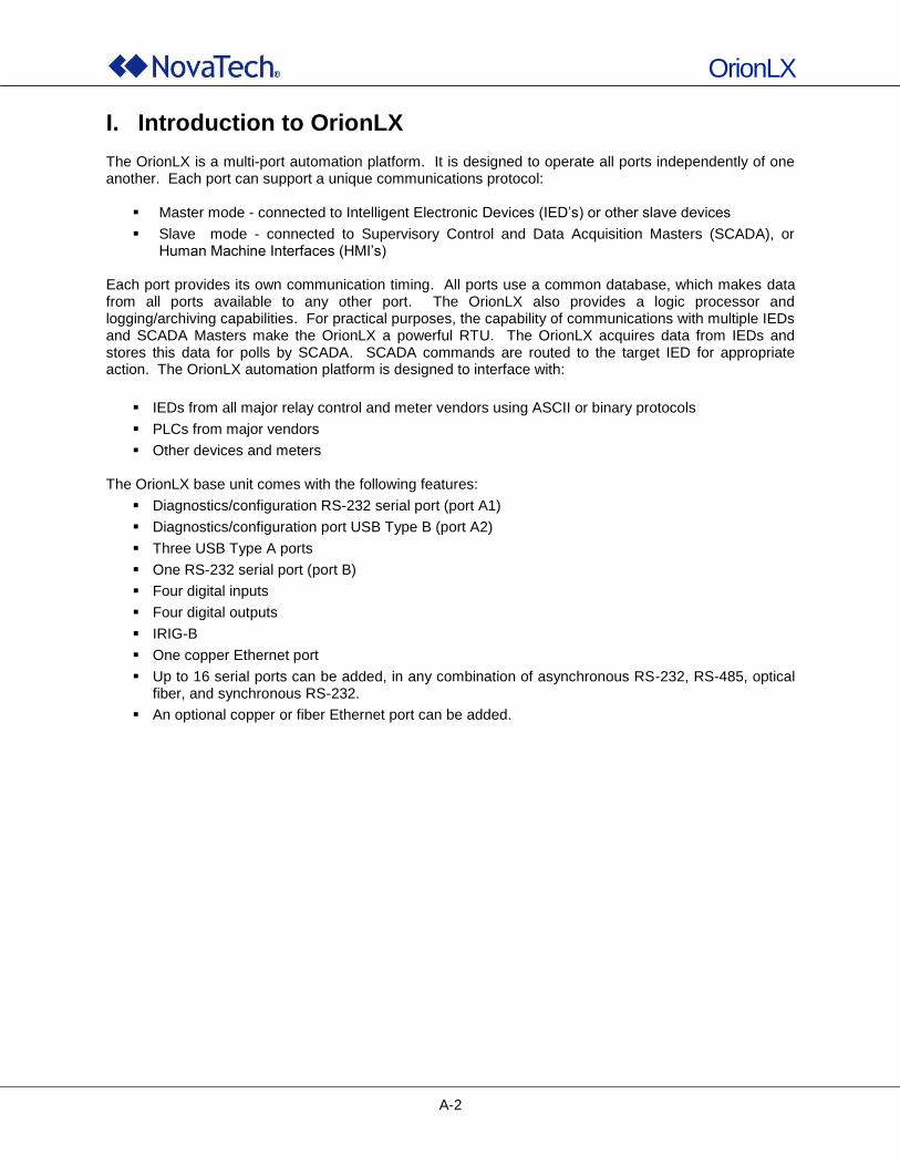
OrionLX
A-2
I. Introduction to OrionLX The OrionLX is a multi-port automation platform. It is designed to operate all ports independently of one another. Each port can support a unique communications protocol:
Master mode - connected to Intelligent Electronic Devices (IED‟s) or other slave devices
Slave mode - connected to Supervisory Control and Data Acquisition Masters (SCADA), or Human Machine Interfaces (HMI‟s)
Each port provides its own communication timing. All ports use a common database, which makes data from all ports available to any other port. The OrionLX also provides a logic processor and logging/archiving capabilities. For practical purposes, the capability of communications with multiple IEDs and SCADA Masters make the OrionLX a powerful RTU. The OrionLX acquires data from IEDs and stores this data for polls by SCADA. SCADA commands are routed to the target IED for appropriate action. The OrionLX automation platform is designed to interface with:
IEDs from all major relay control and meter vendors using ASCII or binary protocols
PLCs from major vendors
Other devices and meters The OrionLX base unit comes with the following features:
Diagnostics/configuration RS-232 serial port (port A1)
Diagnostics/configuration port USB Type B (port A2)
Three USB Type A ports
One RS-232 serial port (port B)
Four digital inputs
Four digital outputs
IRIG-B
One copper Ethernet port
Up to 16 serial ports can be added, in any combination of asynchronous RS-232, RS-485, optical fiber, and synchronous RS-232.
An optional copper or fiber Ethernet port can be added.
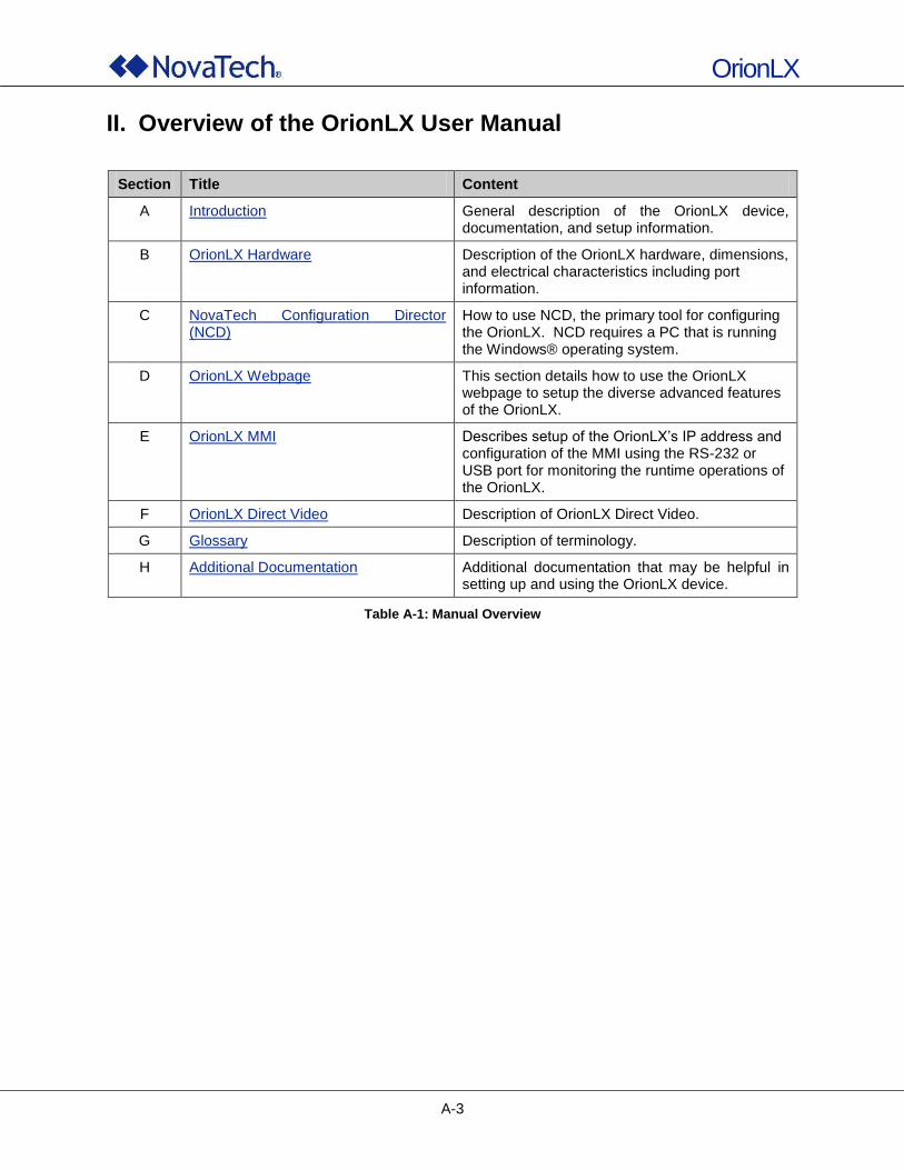
OrionLX
A-3
II. Overview of the OrionLX User Manual
Section Title Content
A Introduction General description of the OrionLX device, documentation, and setup information.
B OrionLX Hardware Description of the OrionLX hardware, dimensions, and electrical characteristics including port information.
C NovaTech Configuration Director (NCD)
How to use NCD, the primary tool for configuring the OrionLX. NCD requires a PC that is running the Windows® operating system.
D OrionLX Webpage This section details how to use the OrionLX webpage to setup the diverse advanced features of the OrionLX.
E OrionLX MMI Describes setup of the OrionLX‟s IP address and configuration of the MMI using the RS-232 or USB port for monitoring the runtime operations of the OrionLX.
F OrionLX Direct Video Description of OrionLX Direct Video.
G Glossary Description of terminology.
H Additional Documentation Additional documentation that may be helpful in setting up and using the OrionLX device.
Table A-1: Manual Overview
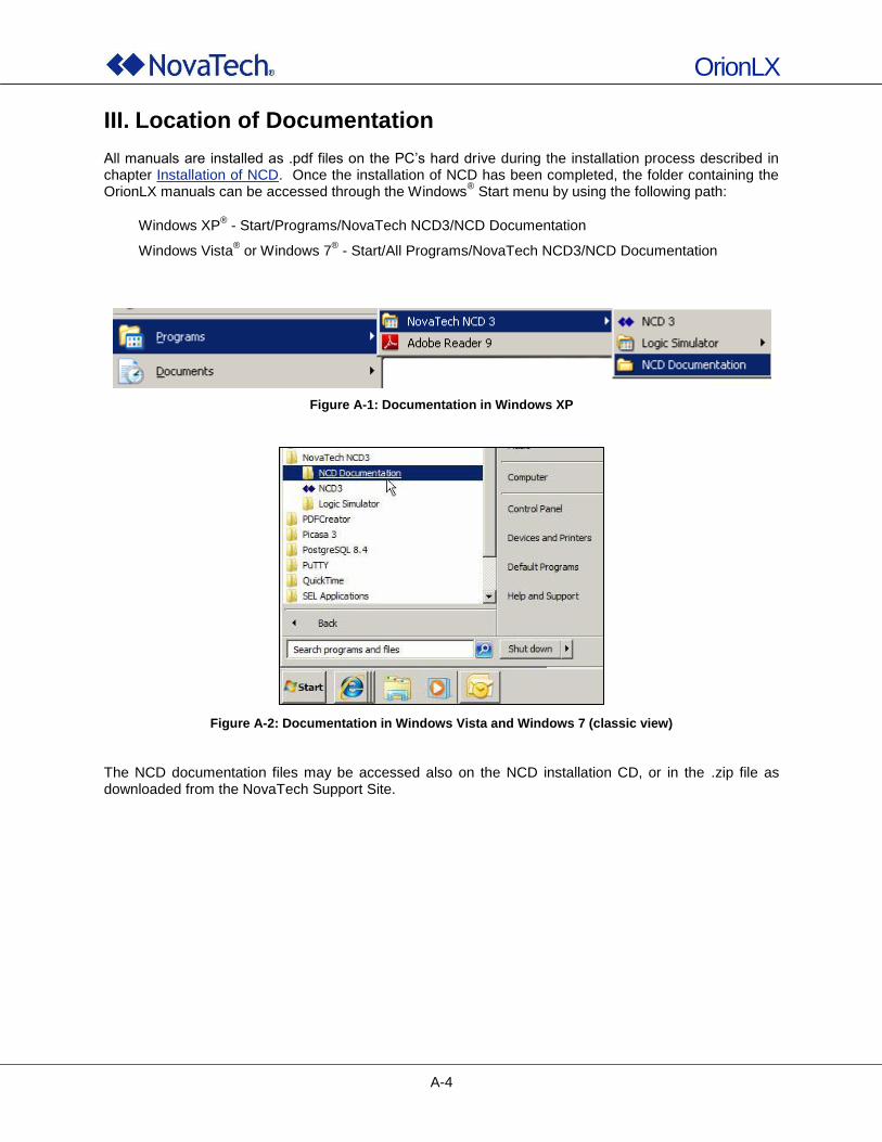
OrionLX
A-4
III. Location of Documentation All manuals are installed as .pdf files on the PC‟s hard drive during the installation process described in chapter Installation of NCD. Once the installation of NCD has been completed, the folder containing the OrionLX manuals can be accessed through the Windows
® Start menu by using the following path:
Windows XP® - Start/Programs/NovaTech NCD3/NCD Documentation
Windows Vista® or Windows 7
® - Start/All Programs/NovaTech NCD3/NCD Documentation
Figure A-1: Documentation in Windows XP
Figure A-2: Documentation in Windows Vista and Windows 7 (classic view)
The NCD documentation files may be accessed also on the NCD installation CD, or in the .zip file as downloaded from the NovaTech Support Site.
OrionLX
A-5
IV. Setup of OrionLX The OrionLX provides a number of hardware and software features that are basically set up in two stages using the NovaTech Configuration Director (NCD) and OrionLX Webpage. This chapter is intended to assist users in setting up the OrionLX most efficiently in terms of required OrionLX features and available engineering resources. The NCD Communications window, or any communication software such as Hyperterminal, can be used to connect to the OrionLX. A web browser is required to access the OrionLX Webpage. Once connected to the OrionLX, configuration files, download archives and logs, and new firmware can be transferred to/from the OrionLX. In addition, the firewall can be configured, data values forced, and communication on any of the communication ports can be logged. The following sections show each feature of the OrionLX and the respective tool used for the setup of each feature. This allows planning of the most efficient setup. Each entry in the table is a hyperlink to the respective section in this manual to provide easy navigation.
1. Setup of OrionLX IP Address As a factory setting, both Ethernet interfaces are configured to use DHCP to obtain IP addresses. In general, static IP addresses must be assigned to each of the OrionLX‟s Ethernet ports. First, connect to Port A1 (serial port) or A2 (USB port) of the OrionLX to set up Ethernet port 0 (ETH0). Setting up this connection to the OrionLX is described in chapter Communications Menu. Then set up the IP address for ETH0 as described in the Network Menu of the OrionLX's MMI. Once the IP address of ETH0 has been set to known address, the OrionLX webpage can be used to configure all remaining network settings as described in chapter Networking.
2. Setup using NCD The full configuration for an OrionLX can be created using NovaTech Configuration Director (NCD), even before the OrionLX is received on site. The following features are set up with NCD:
Selection of OrionLX hardware and port setup
General setup and debug features (forcing I/O)
Synchronous and asynchronous protocols using RS-232 ports and fiber ports, including device properties and I/O point lists
TCP protocols including setup of device properties and I/O lists
Data points for network time protocols/IRIG-B
System/Point Logger (standard software feature)
OrionLED (standard feature)
Sensor Master (standard feature)
Text Module
Orion Math and Logic/Advanced Orion Math and Logic
OrionLX
A-6
NCD sets up the programmable elements that pertain to the applications within the OrionLX, such as communication ports, software features, devices, points lists, logic, etc. If there are several departments involved in the OrionLX setup, the parameters of the programmable elements are typically determined by the engineering, substation, or communications department. The configuration created by the NCD is an ASCII text file, which describes the entire OrionLX configuration. Therefore, if a large number of OrionLX has to be configured, the configuration files can also be created by programming scripts, which use the point and device data already available in the customer engineering department. Once the configuration has been created, it can be loaded into an OrionLX using either the OrionLX‟s serial MMI port, or the Ethernet port. Note: Before connecting to the OrionLX for the first time using an Ethernet port, the OrionLX’s
IP address must first be set by connecting to the serial MMI port (see View/Change Network Configuration).
NCD can be mailed on a CD, or can be downloaded from the OrionLX Support website (http://www.novatech-llc.com/cgi-bin/login.pl) as soon as the customer account has been set up.
3. Setup using OrionLX Webpage The features set up with the OrionLX Webpage are operational features and security features that are typically set up by, or in cooperation with, an IT department.
Time Synchronization: IRIG-B, UTC/Local, Modulated/Unmodulated, NTP Time Source, Time Zone
User Management: Manage users, set rights, allowed services, allowed operations, clearances
Authentication: Lockout rules, password rules, LDAP setup, Remote Root Login
Networking: Set host name, DNS, DHCP, Gateway, IP, Subnet, Media
Firewall: Set input, output, and forwarding rules, start firewall
VPN: Start option, client/server, TCP/UDP, port, cipher, key, server IP address, clients
Key Management: Create and manage key, certificates
Services: Allow/Disallow Telnet, FTP, HTTP
OrionLX
A-7
4. Setup Worksheet The following worksheet in Table A-2 assists in configuring an OrionLX most efficiently. The Feature column describes the features offered by the OrionLX. For each feature, the respective configuration tool is described in columns Offline Configuration with NCD or Online Configuration with Webpage. Steps in columns Offline Configuration with NCD and Online Configuration with Webpage can be performed one after the other by the same engineers, or in parallel. For example, the Substation Department can use NCD to set up field devices and I/O lists, while the IT Department can set up the OrionLX‟s network settings using the OrionLX‟s webpage. Before the OrionLX‟s webpage can be accessed with a web browser, the OrionLX‟s IP address must be set up. This is done as described in chapter Network Menu of the OrionLX MMI. It requires a serial port, and the NovaTech serial cable included with OrionLX, or a USB port and USB cable. Drivers for the USB connection may be downloaded from the OrionLX support webpage. To use Alarm/Archive/Retentive the database must be enabled and reset from the webpage.
Once the Offline Configuration with NCD is completed, the .ncd file created by NCD must be transferred
to the OrionLX. This can be done using a serial connection or an Ethernet connection between the PC and the OrionLX.
5. Change of Passwords In the course of, or after completing the setup of the OrionLX, the default passwords must be changed in order to establish secure operations. This is explained in chapter Password Change.
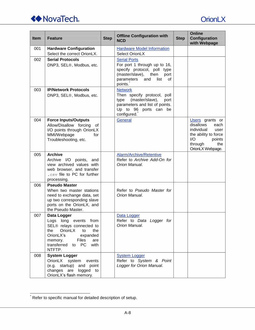
OrionLX
A-8
Item Feature Step Offline Configuration with NCD
Step Online Configuration with Webpage
001 Hardware Configuration
Select the correct OrionLX.
Hardware Model Information
Select OrionLX
002 Serial Protocols
DNP3, SEL, Modbus, etc.
Serial Ports
For port 1 through up to 16, specify protocol, poll type (master/slave), then port parameters and list of points.
*
003 IP/Network Protocols
DNP3, SEL, Modbus, etc.
Network
Then specify protocol, poll type (master/slave), port parameters and list of points. Up to 96 ports can be configured.
*
004 Force Inputs/Outputs
Allow/Disallow forcing of I/O points through OrionLX MMI/Webpage for Troubleshooting, etc.
General Users grants or disallows each individual user the ability to force I/O points through the OrionLX Webpage.
005 Archive
Archive I/O points, and view archived values with web browser, and transfer
.csv file to PC for further
processing.
Alarm/Archive/Retentive
Refer to Archive Add-On for
Orion Manual.
006 Pseudo Master
When two master stations need to exchange data, set up two corresponding slave ports on the OrionLX, and the Pseudo Master.
Refer to Pseudo Master for Orion Manual.
007 Data Logger
Logs long events from
SEL relays connected to the OrionLX to the OrionLX‟s expanded memory. Files are transferred to PC with NTFTP.
Data Logger
Refer to Data Logger for Orion Manual.
008 System Logger
OrionLX system events (e.g. startup) and point changes are logged to OrionLX‟s flash memory.
System Logger
Refer to System & Point Logger for Orion Manual.
* Refer to specific manual for detailed description of setup.
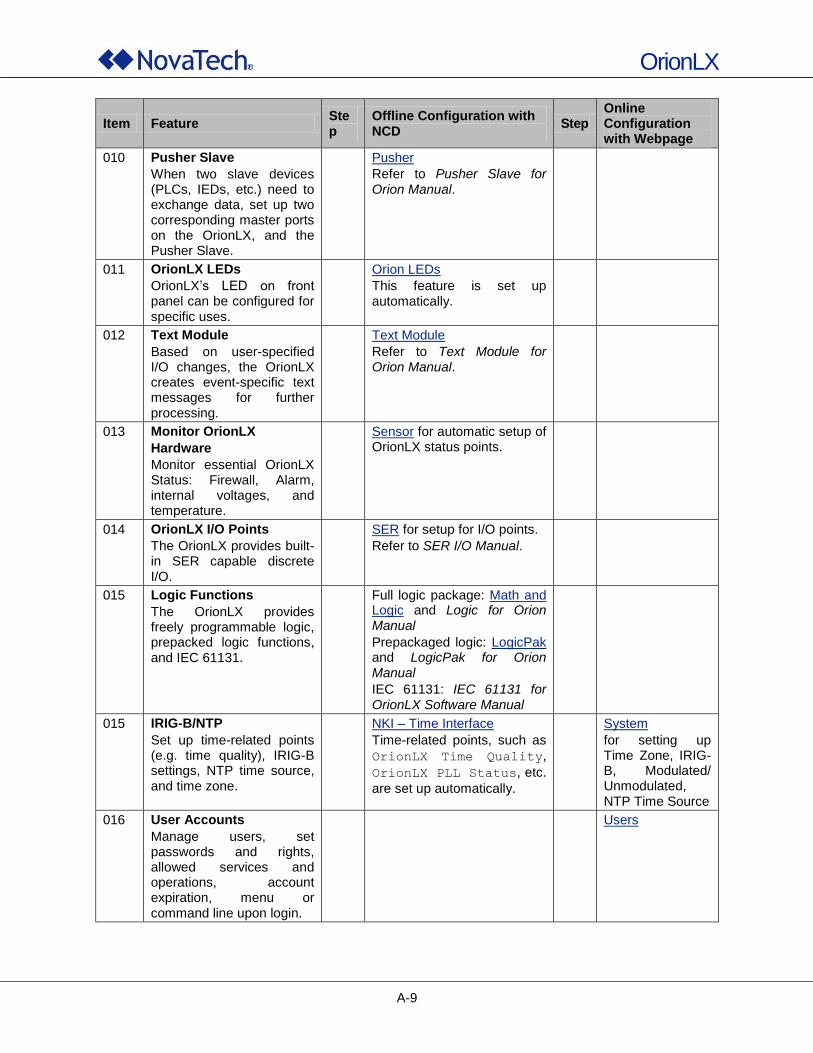
OrionLX
A-9
Item Feature Step
Offline Configuration with NCD
Step Online Configuration with Webpage
010 Pusher Slave
When two slave devices (PLCs, IEDs, etc.) need to exchange data, set up two corresponding master ports on the OrionLX, and the Pusher Slave.
Pusher
Refer to Pusher Slave for Orion Manual.
011 OrionLX LEDs
OrionLX‟s LED on front panel can be configured for specific uses.
Orion LEDs
This feature is set up automatically.
012 Text Module
Based on user-specified I/O changes, the OrionLX creates event-specific text messages for further processing.
Text Module
Refer to Text Module for Orion Manual.
013 Monitor OrionLX
Hardware
Monitor essential OrionLX Status: Firewall, Alarm, internal voltages, and temperature.
Sensor for automatic setup of OrionLX status points.
014 OrionLX I/O Points
The OrionLX provides built-in SER capable discrete I/O.
SER for setup for I/O points.
Refer to SER I/O Manual.
015 Logic Functions
The OrionLX provides freely programmable logic, prepacked logic functions, and IEC 61131.
Full logic package: Math and Logic and Logic for Orion Manual
Prepackaged logic: LogicPak and LogicPak for Orion Manual
IEC 61131: IEC 61131 for OrionLX Software Manual
015 IRIG-B/NTP
Set up time-related points (e.g. time quality), IRIG-B settings, NTP time source, and time zone.
NKI – Time Interface
Time-related points, such as
OrionLX Time Quality,
OrionLX PLL Status, etc.
are set up automatically.
System
for setting up Time Zone, IRIG-B, Modulated/ Unmodulated, NTP Time Source
016 User Accounts
Manage users, set passwords and rights, allowed services and operations, account expiration, menu or command line upon login.
Users
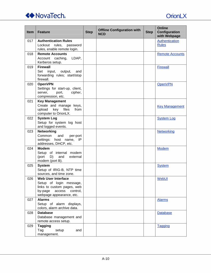
OrionLX
A-10
Item Feature Step Offline Configuration with NCD
Step Online Configuration with Webpage
017 Authentication Rules
Lockout rules, password rules, enable remote login.
Authentication Rules
018 Remote Accounts
Account caching, LDAP, Kerberos setup.
Remote Accounts
019 Firewall
Set input, output, and forwarding rules; start/stop firewall.
Firewall
020 OpenVPN
Settings for start-up, client, server, port, cipher, compression, etc.
OpenVPN
021 Key Management
Create and manage keys, upload key files from computer to OrionLX.
Key Management
022 System Log
Setup for system log host and logged events.
System Log
023 Networking
Common and per-port settings: host name, IP addresses, DHCP, etc.
Networking
024 Modem
Setup of internal modem (port D) and external modem (port B).
Modem
025 System
Setup of IRIG-B, NTP time sources, and time zone.
System
026 Web User Interface
Setup of login message, links to custom pages, web by-page access control, webpage appearance, etc.
WebUI
027 Alarms
Setup of alarm displays, colors, alarm archive data.
Alarms
028 Database
Database management and remote access setup.
Database
029 Tagging
Tag setup and management.
Tagging
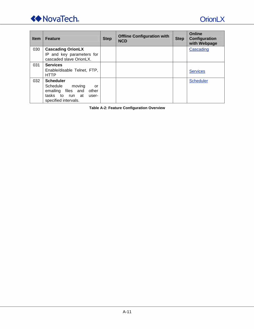
OrionLX
A-11
Item Feature Step Offline Configuration with NCD
Step Online Configuration with Webpage
030 Cascading OrionLX
IP and key parameters for cascaded slave OrionLX.
Cascading
031 Services
Enable/disable Telnet, FTP, HTTP
Services
032 Scheduler
Schedule moving or emailing files and other tasks to run at user-specified intervals.
Scheduler
Table A-2: Feature Configuration Overview
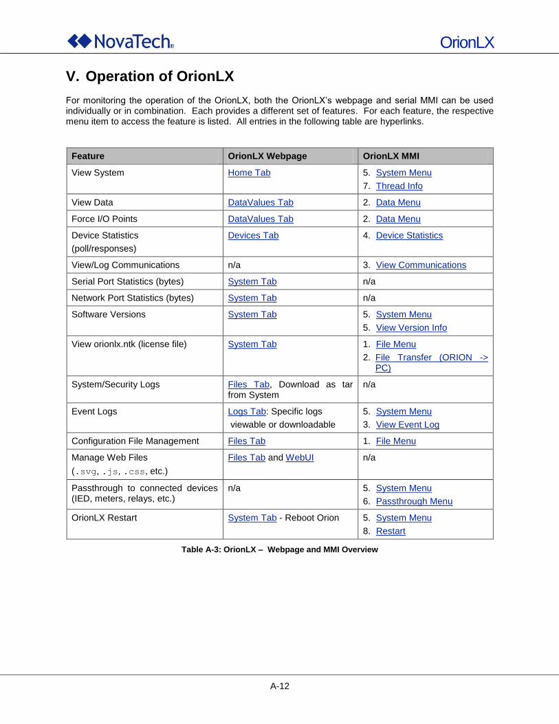
OrionLX
A-12
V. Operation of OrionLX For monitoring the operation of the OrionLX, both the OrionLX‟s webpage and serial MMI can be used individually or in combination. Each provides a different set of features. For each feature, the respective menu item to access the feature is listed. All entries in the following table are hyperlinks.
Feature OrionLX Webpage OrionLX MMI
View System Home Tab 5. System Menu
7. Thread Info
View Data DataValues Tab 2. Data Menu
Force I/O Points DataValues Tab 2. Data Menu
Device Statistics
(poll/responses)
Devices Tab 4. Device Statistics
View/Log Communications n/a 3. View Communications
Serial Port Statistics (bytes) System Tab n/a
Network Port Statistics (bytes) System Tab n/a
Software Versions System Tab 5. System Menu
5. View Version Info
View orionlx.ntk (license file) System Tab 1. File Menu
2. File Transfer (ORION -> PC)
System/Security Logs Files Tab, Download as tar from System
n/a
Event Logs Logs Tab: Specific logs
viewable or downloadable
5. System Menu
3. View Event Log
Configuration File Management Files Tab 1. File Menu
Manage Web Files
(.svg, .js, .css, etc.)
Files Tab and WebUI n/a
Passthrough to connected devices (IED, meters, relays, etc.)
n/a 5. System Menu
6. Passthrough Menu
OrionLX Restart System Tab - Reboot Orion 5. System Menu
8. Restart
Table A-3: OrionLX – Webpage and MMI Overview

OrionLX
B-1
B. OrionLX Hardware
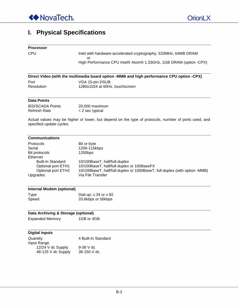
OrionLX
B-2
I. Physical Specifications
Processor
CPU Intel with hardware-accelerated cryptography, 533MHz, 64MB DRAM or High Performance CPU Intel® Atom® 1.33GHz, 1GB DRAM (option -CPX)
Direct Video (with the multimedia board option -MMB and high performance CPU option -CPX)
Port VGA 15-pin DSUB Resolution 1280x1024 at 60Hz, touchscreen
Data Points
IED/SCADA Points 20,000 maximum Refresh Rate < 2 sec typical Actual values may be higher or lower, but depend on the type of protocols, number of ports used, and specified update cycles.
Communications
Protocols Bit or byte Serial 1200-115kbps Bit protocols 1200bps Ethernet
Built-In Standard 10/100BaseT, half/full-duplex Optional port ETH1 10/100BaseT, half/full-duplex or 100BaseFX Optional port ETH2 10/100BaseT, half/full-duplex or 1000BaseT, full-duplex (with option -MMB)
Upgrades Via File Transfer
Internal Modem (optional)
Type Dial-up; v.34 or v.92 Speed 33.6kbps or 56kbps
Data Archiving & Storage (optional)
Expanded Memory 1GB or 4GB
Digital Inputs
Quantity 4 Built-In Standard Input Range
12/24 V dc Supply 9-36 V dc 48-125 V dc Supply 36-150 V dc
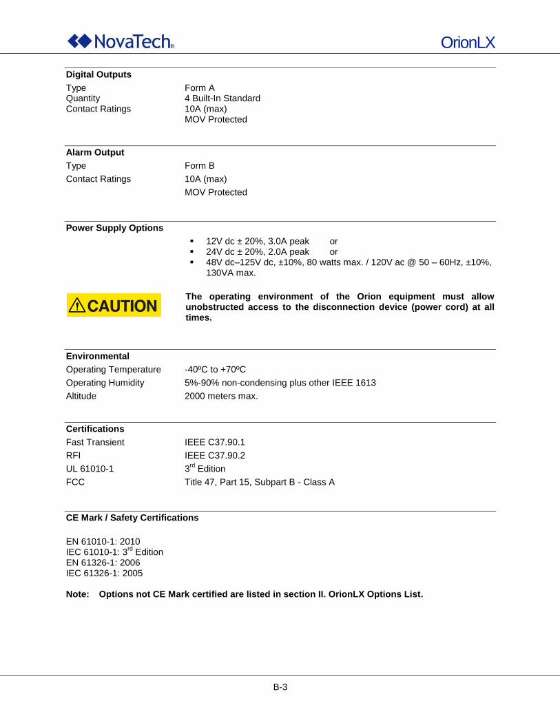
OrionLX
B-3
Digital Outputs
Type Form A Quantity 4 Built-In Standard Contact Ratings 10A (max)
MOV Protected
Alarm Output
Type Form B
Contact Ratings 10A (max)
MOV Protected
Power Supply Options
12V dc ± 20%, 3.0A peak or 24V dc ± 20%, 2.0A peak or 48V dc–125V dc, ±10%, 80 watts max. / 120V ac @ 50 – 60Hz, ±10%,
130VA max.
The operating environment of the Orion equipment must allow unobstructed access to the disconnection device (power cord) at all times.
Environmental
Operating Temperature -40ºC to +70ºC
Operating Humidity 5%-90% non-condensing plus other IEEE 1613
Altitude 2000 meters max.
Certifications
Fast Transient IEEE C37.90.1
RFI IEEE C37.90.2
UL 61010-1 3rd
Edition
FCC Title 47, Part 15, Subpart B - Class A
CE Mark / Safety Certifications
EN 61010-1: 2010 IEC 61010-1: 3
rd Edition
EN 61326-1: 2006 IEC 61326-1: 2005 Note: Options not CE Mark certified are listed in section II. OrionLX Options List.
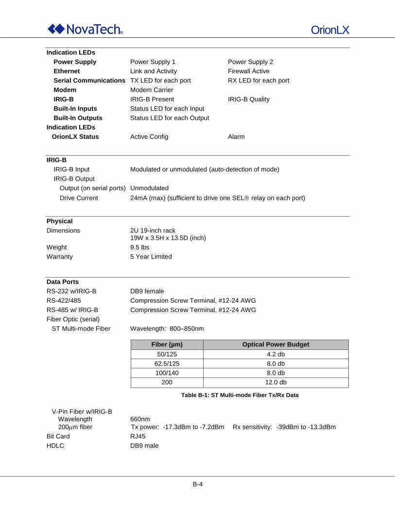
OrionLX
B-4
Indication LEDs
Power Supply Power Supply 1 Power Supply 2
Ethernet Link and Activity Firewall Active
Serial Communications TX LED for each port RX LED for each port
Modem Modem Carrier
IRIG-B IRIG-B Present IRIG-B Quality
Built-In Inputs Status LED for each Input
Built-In Outputs Status LED for each Output
Indication LEDs
OrionLX Status Active Config Alarm
IRIG-B
IRIG-B Input Modulated or unmodulated (auto-detection of mode)
IRIG-B Output
Output (on serial ports) Unmodulated
Drive Current 24mA (max) (sufficient to drive one SEL relay on each port)
Physical
Dimensions 2U 19-inch rack 19W x 3.5H x 13.5D (inch)
Weight 9.5 lbs
Warranty 5 Year Limited
Data Ports
RS-232 w/IRIG-B DB9 female
RS-422/485 Compression Screw Terminal, #12-24 AWG
RS-485 w/ IRIG-B Compression Screw Terminal, #12-24 AWG
Fiber Optic (serial)
ST Multi-mode Fiber Wavelength: 800–850nm
Fiber (µm) Optical Power Budget
50/125 4.2 db
62.5/125 8.0 db
100/140 8.0 db
200 12.0 db
Table B-1: ST Multi-mode Fiber Tx/Rx Data
V-Pin Fiber w/IRIG-B Wavelength 660nm
200m fiber Tx power: -17.3dBm to -7.2dBm Rx sensitivity: -39dBm to -13.3dBm
Bit Card RJ45
HDLC DB9 male
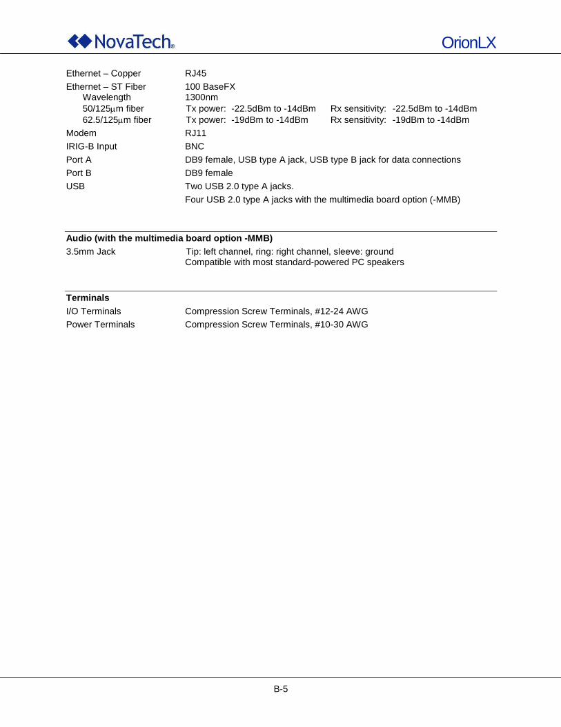
OrionLX
B-5
Ethernet – Copper RJ45
Ethernet – ST Fiber 100 BaseFX Wavelength 1300nm
50/125m fiber Tx power: -22.5dBm to -14dBm Rx sensitivity: -22.5dBm to -14dBm
62.5/125m fiber Tx power: -19dBm to -14dBm Rx sensitivity: -19dBm to -14dBm
Modem RJ11
IRIG-B Input BNC
Port A DB9 female, USB type A jack, USB type B jack for data connections
Port B DB9 female
USB Two USB 2.0 type A jacks.
Four USB 2.0 type A jacks with the multimedia board option (-MMB)
Audio (with the multimedia board option -MMB)
3.5mm Jack Tip: left channel, ring: right channel, sleeve: ground Compatible with most standard-powered PC speakers
Terminals
I/O Terminals Compression Screw Terminals, #12-24 AWG
Power Terminals Compression Screw Terminals, #10-30 AWG
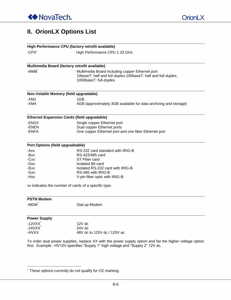
OrionLX
B-6
II. OrionLX Options List
High Performance CPU (factory retrofit available)
-CPX High Performance CPU 1.33 GHz
Multimedia Board (factory retrofit available)
-MMB* Multimedia Board including copper Ethernet port
10baseT: half and full duplex,100baseT: half and full duplex, 1000baseT: full-duplex
Non-Volatile Memory (field upgradable)
-XM1 1GB -XM4 4GB (approximately 3GB available for data archiving and storage)
Ethernet Expansion Cards (field upgradable)
-ENXX Single copper Ethernet port -ENEN Dual copper Ethernet ports -ENFA One copper Ethernet port and one fiber Ethernet port
Port Options (field upgradeable)
-Axx RS-232 card standard with IRIG-B -Bxx RS-422/485 card -Cxx ST Fiber card -Dxx Isolated Bit card -Exx Isolated RS-232 card with IRIG-B -Gxx RS-485 with IRIG-B -Hxx V-pin fiber optic with IRIG-B xx indicates the number of cards of a specific type.
PSTN Modem
-MDM* Dial-up Modem
Power Supply
-12VXX* 12V dc
-24VXX* 24V dc
-HVXX 48V dc to 125V dc / 120V ac To order dual power supplies, replace XX with the power supply option and list the higher voltage option first. Example: -HV12V specifies “Supply 1” high voltage and “Supply 2” 12V dc.
These options currently do not qualify for CE marking.
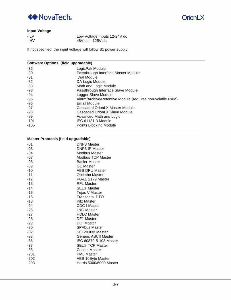
OrionLX
B-7
Input Voltage
-ILV Low Voltage Inputs 12-24V dc -IHV 48V dc – 125V dc If not specified, the input voltage will follow S1 power supply.
Software Options (field upgradable)
-35 LogicPak Module -80 Passthrough Interface Master Module -81 iDial Module -82 DA Logic Module -83 Math and Logic Module -93 Passthrough Interface Slave Module -94 Logger Slave Module -95 Alarm/Archive/Retentive Module (requires non-volatile RAM) -96 Email Module -97 Cascaded OrionLX Master Module -98 Cascaded OrionLX Slave Module -99 Advanced Math and Logic -101 IEC 61131-3 Module -105 Points Blocking Module
Master Protocols (field upgradable)
-01 DNP3 Master -03 DNP3 IP Master -04 Modbus Master -07 Modbus TCP Master -08 Basler Master -09 GE Master -10 ABB DPU Master -11 Optimho Master -12 PG&E 2179 Master -13 RFL Master
-14 SEL Master -15 Tejas V Master -16 Transdata DTO -18 Kitz Master -24 CDC-I Master -25 L&G Master -27 HDLC Master -28 DF1 Master -29 DQI Master -30 SPAbus Master
-32 SEL2030 Master -33 Generic ASCII Master -36 IEC 60870-5-103 Master
-37 SEL TCP Master -38 Conitel Master -201 PML Master -202 ABB 10Byte Master -203 Harris 5000/6000 Master
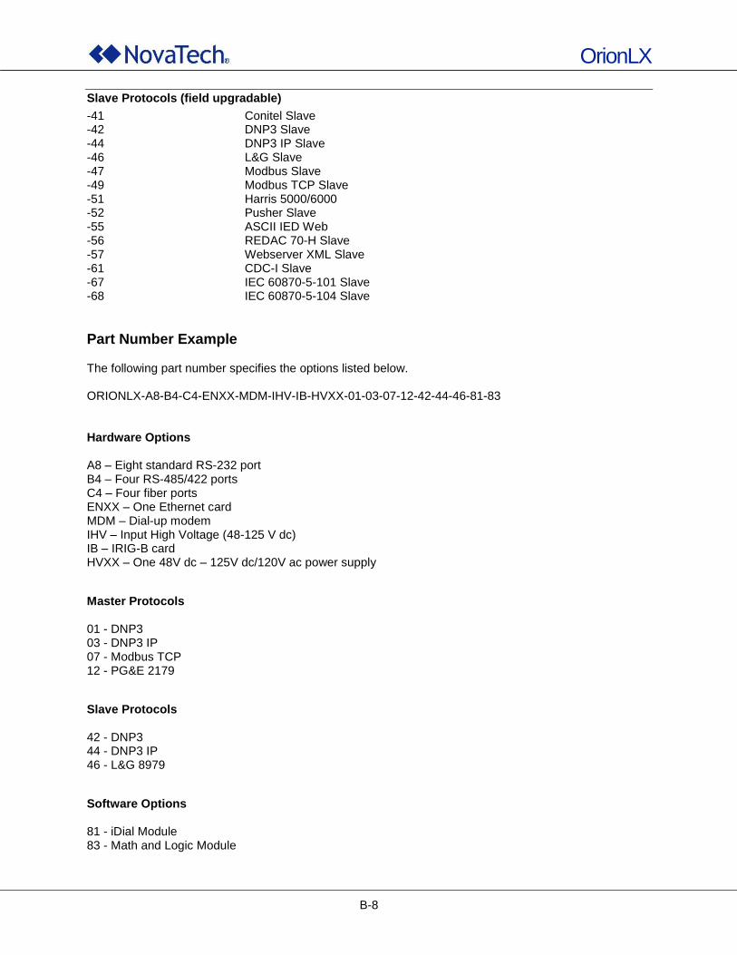
OrionLX
B-8
Slave Protocols (field upgradable)
-41 Conitel Slave -42 DNP3 Slave -44 DNP3 IP Slave -46 L&G Slave -47 Modbus Slave -49 Modbus TCP Slave -51 Harris 5000/6000 -52 Pusher Slave -55 ASCII IED Web -56 REDAC 70-H Slave -57 Webserver XML Slave -61 CDC-I Slave -67 IEC 60870-5-101 Slave -68 IEC 60870-5-104 Slave
Part Number Example The following part number specifies the options listed below. ORIONLX-A8-B4-C4-ENXX-MDM-IHV-IB-HVXX-01-03-07-12-42-44-46-81-83 Hardware Options A8 – Eight standard RS-232 port B4 – Four RS-485/422 ports C4 – Four fiber ports ENXX – One Ethernet card MDM – Dial-up modem IHV – Input High Voltage (48-125 V dc) IB – IRIG-B card HVXX – One 48V dc – 125V dc/120V ac power supply
Master Protocols 01 - DNP3 03 - DNP3 IP 07 - Modbus TCP 12 - PG&E 2179
Slave Protocols 42 - DNP3 44 - DNP3 IP 46 - L&G 8979
Software Options 81 - iDial Module 83 - Math and Logic Module
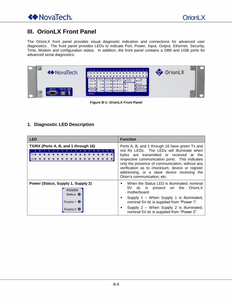
OrionLX
B-9
III. OrionLX Front Panel The OrionLX front panel provides visual diagnostic indication and connections for advanced user diagnostics. The front panel provides LEDs to indicate Port, Power, Input, Output, Ethernet, Security, Time, Modem and configuration status. In addition, the front panel contains a DB9 and USB ports for advanced serial diagnostics.
Figure B-1: OrionLX Front Panel
1. Diagnostic LED Description
LED Function
TX/RX (Ports A, B, and 1 through 16)
Ports A, B, and 1 through 16 have green Tx and red Rx LEDs. The LEDs will illuminate when bytes are transmitted or received at the respective communication ports. This indicates only the presence of communication, without any verification as to checksum, device or register addressing, or a slave device receiving the Orion‟s communication, etc.
Power (Status, Supply 1, Supply 2)
When the Status LED is illuminated, nominal 5V dc is present on the OrionLX motherboard.
Supply 1 – When Supply 1 is illuminated, nominal 5V dc is supplied from “Power 1”.
Supply 2 – When Supply 2 is illuminated, nominal 5V dc is supplied from “Power 2”.
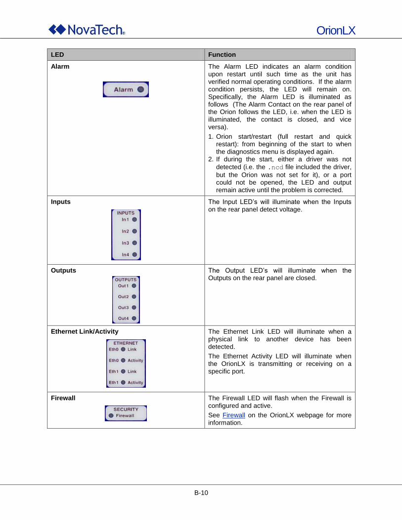
OrionLX
B-10
LED Function
Alarm
The Alarm LED indicates an alarm condition upon restart until such time as the unit has verified normal operating conditions. If the alarm condition persists, the LED will remain on. Specifically, the Alarm LED is illuminated as follows (The Alarm Contact on the rear panel of the Orion follows the LED, i.e. when the LED is illuminated, the contact is closed, and vice versa).
1. Orion start/restart (full restart and quick restart): from beginning of the start to when the diagnostics menu is displayed again.
2. If during the start, either a driver was not
detected (i.e. the .ncd file included the driver,
but the Orion was not set for it), or a port could not be opened, the LED and output remain active until the problem is corrected.
Inputs
The Input LED‟s will illuminate when the Inputs on the rear panel detect voltage.
Outputs
The Output LED‟s will illuminate when the Outputs on the rear panel are closed.
Ethernet Link/Activity
The Ethernet Link LED will illuminate when a physical link to another device has been detected.
The Ethernet Activity LED will illuminate when the OrionLX is transmitting or receiving on a specific port.
Firewall
The Firewall LED will flash when the Firewall is configured and active.
See Firewall on the OrionLX webpage for more information.
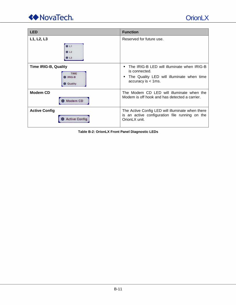
OrionLX
B-11
LED Function
L1, L2, L3
Reserved for future use.
Time IRIG-B, Quality
The IRIG-B LED will illuminate when IRIG-B is connected.
The Quality LED will illuminate when time accuracy is < 1ms.
Modem CD
The Modem CD LED will illuminate when the Modem is off hook and has detected a carrier.
Active Config
The Active Config LED will illuminate when there is an active configuration file running on the OrionLX unit.
Table B-2: OrionLX Front Panel Diagnostic LEDs
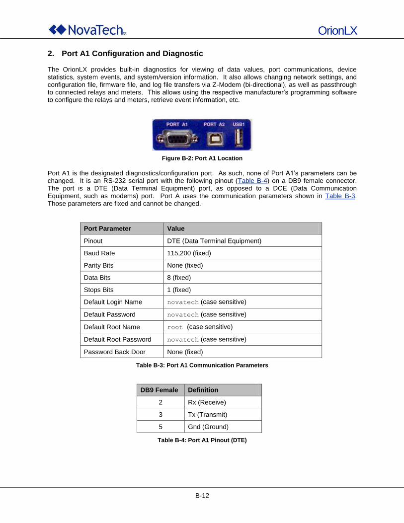
OrionLX
B-12
2. Port A1 Configuration and Diagnostic The OrionLX provides built-in diagnostics for viewing of data values, port communications, device statistics, system events, and system/version information. It also allows changing network settings, and configuration file, firmware file, and log file transfers via Z-Modem (bi-directional), as well as passthrough to connected relays and meters. This allows using the respective manufacturer‟s programming software to configure the relays and meters, retrieve event information, etc.
Figure B-2: Port A1 Location
Port A1 is the designated diagnostics/configuration port. As such, none of Port A1‟s parameters can be changed. It is an RS-232 serial port with the following pinout (Table B-4) on a DB9 female connector. The port is a DTE (Data Terminal Equipment) port, as opposed to a DCE (Data Communication Equipment, such as modems) port. Port A uses the communication parameters shown in Table B-3. Those parameters are fixed and cannot be changed.
Port Parameter Value
Pinout DTE (Data Terminal Equipment)
Baud Rate 115,200 (fixed)
Parity Bits None (fixed)
Data Bits 8 (fixed)
Stops Bits 1 (fixed)
Default Login Name novatech (case sensitive)
Default Password novatech (case sensitive)
Default Root Name root (case sensitive)
Default Root Password novatech (case sensitive)
Password Back Door None (fixed)
Table B-3: Port A1 Communication Parameters
DB9 Female Definition
2 Rx (Receive)
3 Tx (Transmit)
5 Gnd (Ground)
Table B-4: Port A1 Pinout (DTE)
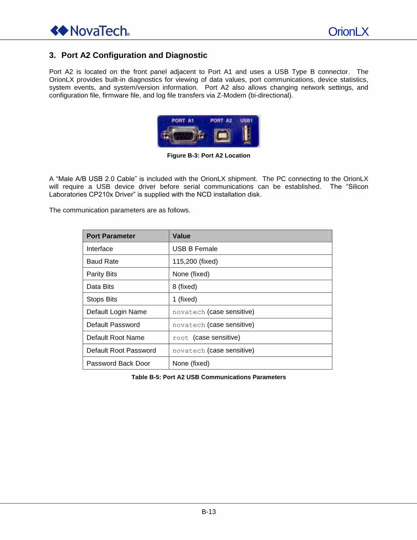
OrionLX
B-13
3. Port A2 Configuration and Diagnostic Port A2 is located on the front panel adjacent to Port A1 and uses a USB Type B connector. The OrionLX provides built-in diagnostics for viewing of data values, port communications, device statistics, system events, and system/version information. Port A2 also allows changing network settings, and configuration file, firmware file, and log file transfers via Z-Modem (bi-directional).
Figure B-3: Port A2 Location
A “Male A/B USB 2.0 Cable” is included with the OrionLX shipment. The PC connecting to the OrionLX will require a USB device driver before serial communications can be established. The “Silicon Laboratories CP210x Driver” is supplied with the NCD installation disk. The communication parameters are as follows.
Port Parameter Value
Interface USB B Female
Baud Rate 115,200 (fixed)
Parity Bits None (fixed)
Data Bits 8 (fixed)
Stops Bits 1 (fixed)
Default Login Name novatech (case sensitive)
Default Password novatech (case sensitive)
Default Root Name root (case sensitive)
Default Root Password novatech (case sensitive)
Password Back Door None (fixed)
Table B-5: Port A2 USB Communications Parameters
OrionLX
B-14
4. USB Ports The OrionLX is equipped with three USB A-type ports. USB1 is located adjacent to Port A1 on the front panel of the OrionLX (see Figure B-1), and uses a USB A-type connector. USB Ports 2 and 3 are located on the OrionLX Rear Panel (see Figure B-5), and use USB A-type connectors. These ports can be used for approved peripheral devices such as USB flash drives to transfer files. If the Multimedia Board option (-MMB) is installed (see Figure F-2), two additional USB ports are available for keyboard and mouse.
5. LED Test The OrionLX is equipped with an LED test button. When pressed, all LEDs will illuminate until the button is released. Once released, the LEDs will return to normal functionality. This button is recessed and requires a precision screwdriver or paper clip to press.
Figure B-4: LED Test Button
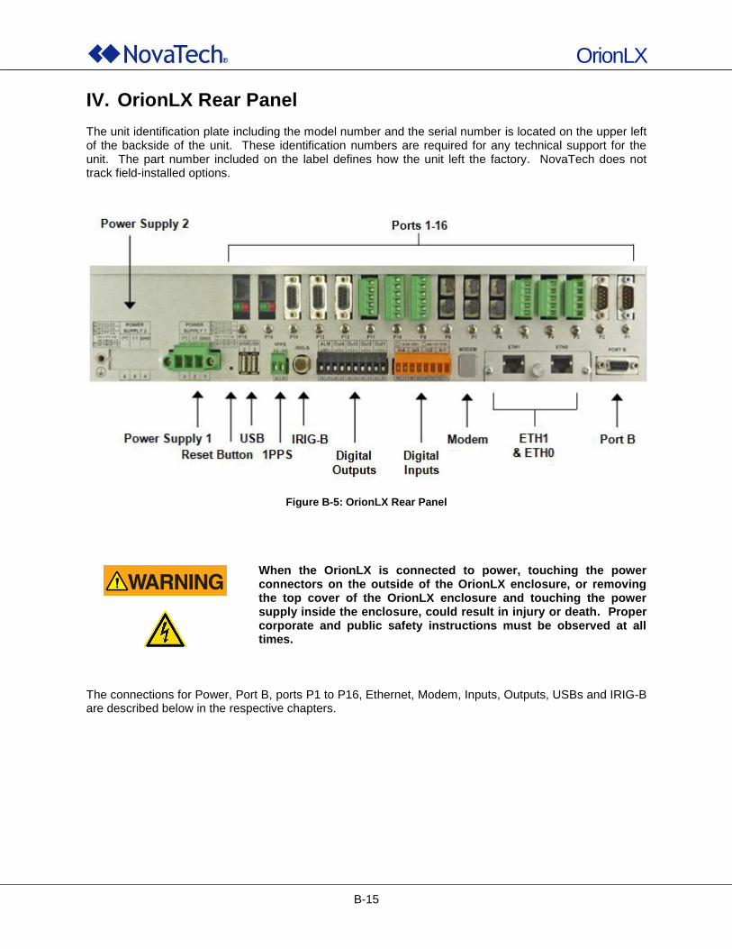
OrionLX
B-15
IV. OrionLX Rear Panel The unit identification plate including the model number and the serial number is located on the upper left of the backside of the unit. These identification numbers are required for any technical support for the unit. The part number included on the label defines how the unit left the factory. NovaTech does not track field-installed options.
Figure B-5: OrionLX Rear Panel
When the OrionLX is connected to power, touching the power connectors on the outside of the OrionLX enclosure, or removing the top cover of the OrionLX enclosure and touching the power supply inside the enclosure, could result in injury or death. Proper corporate and public safety instructions must be observed at all times.
The connections for Power, Port B, ports P1 to P16, Ethernet, Modem, Inputs, Outputs, USBs and IRIG-B are described below in the respective chapters.

OrionLX
B-16
1. Power Connections The OrionLX power input is located at the bottom left of the rear panel. The OrionLX offers several power supply options as well as an optional second power supply. For each of the power supplies, its voltage is indicated on the label above it as shown in the following figure.
Figure B-6: OrionLX Power Connections
#10-30 AWG wire is recommended, stripping the insulation between 1/4” to 3/8”. The GND lug is a #8 stainless steel screw that is connected to chassis, and must be connected to Earth Ground. A size #8 ring or spade lug connector is recommended. NovaTech recommends that all grounding be performed in accordance with ANSI/IEEE C57.13.3-1983. The OrionLX uses removable screw terminal compression fittings for user power connections. These connectors are keyed by voltage level so that a plug keyed for one voltage level cannot be plugged into a socket keyed for another voltage level. See example in Figure B-7.
Figure B-7: OrionLX Female and Male Power Connector Keyed for 12V dc
Supply Input Range Male Connector Key
48-125V dc / 125V ac 110
24V dc 010
12V dc 001
Table B-6: OrionLX Male Connector Keying
Key Key Slot
Key slot Key
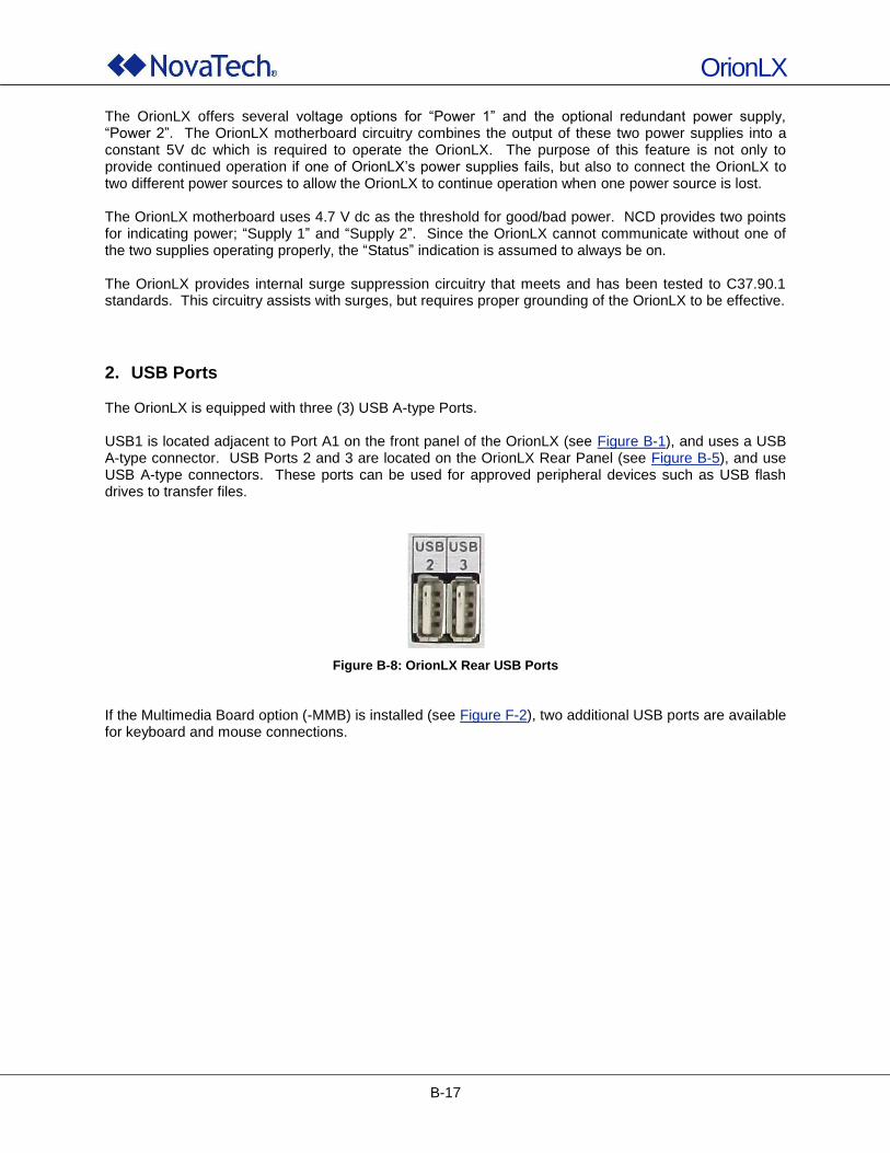
OrionLX
B-17
The OrionLX offers several voltage options for “Power 1” and the optional redundant power supply, “Power 2”. The OrionLX motherboard circuitry combines the output of these two power supplies into a constant 5V dc which is required to operate the OrionLX. The purpose of this feature is not only to provide continued operation if one of OrionLX‟s power supplies fails, but also to connect the OrionLX to two different power sources to allow the OrionLX to continue operation when one power source is lost. The OrionLX motherboard uses 4.7 V dc as the threshold for good/bad power. NCD provides two points for indicating power; “Supply 1” and “Supply 2”. Since the OrionLX cannot communicate without one of the two supplies operating properly, the “Status” indication is assumed to always be on. The OrionLX provides internal surge suppression circuitry that meets and has been tested to C37.90.1 standards. This circuitry assists with surges, but requires proper grounding of the OrionLX to be effective.
2. USB Ports The OrionLX is equipped with three (3) USB A-type Ports. USB1 is located adjacent to Port A1 on the front panel of the OrionLX (see Figure B-1), and uses a USB A-type connector. USB Ports 2 and 3 are located on the OrionLX Rear Panel (see Figure B-5), and use USB A-type connectors. These ports can be used for approved peripheral devices such as USB flash drives to transfer files.
Figure B-8: OrionLX Rear USB Ports
If the Multimedia Board option (-MMB) is installed (see Figure F-2), two additional USB ports are available for keyboard and mouse connections.
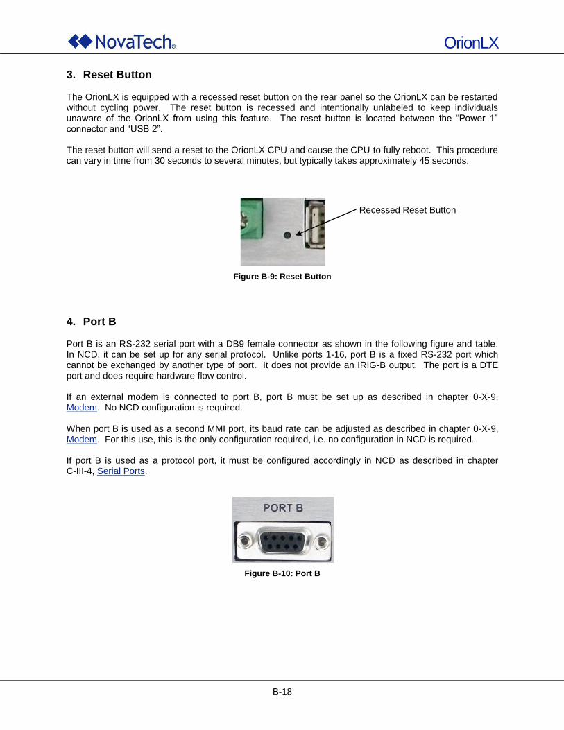
OrionLX
B-18
3. Reset Button The OrionLX is equipped with a recessed reset button on the rear panel so the OrionLX can be restarted without cycling power. The reset button is recessed and intentionally unlabeled to keep individuals unaware of the OrionLX from using this feature. The reset button is located between the “Power 1” connector and “USB 2”. The reset button will send a reset to the OrionLX CPU and cause the CPU to fully reboot. This procedure can vary in time from 30 seconds to several minutes, but typically takes approximately 45 seconds.
Figure B-9: Reset Button
4. Port B Port B is an RS-232 serial port with a DB9 female connector as shown in the following figure and table. In NCD, it can be set up for any serial protocol. Unlike ports 1-16, port B is a fixed RS-232 port which cannot be exchanged by another type of port. It does not provide an IRIG-B output. The port is a DTE port and does require hardware flow control. If an external modem is connected to port B, port B must be set up as described in chapter 0-X-9, Modem. No NCD configuration is required. When port B is used as a second MMI port, its baud rate can be adjusted as described in chapter 0-X-9, Modem. For this use, this is the only configuration required, i.e. no configuration in NCD is required. If port B is used as a protocol port, it must be configured accordingly in NCD as described in chapter C-III-4, Serial Ports.
Figure B-10: Port B
Recessed Reset Button
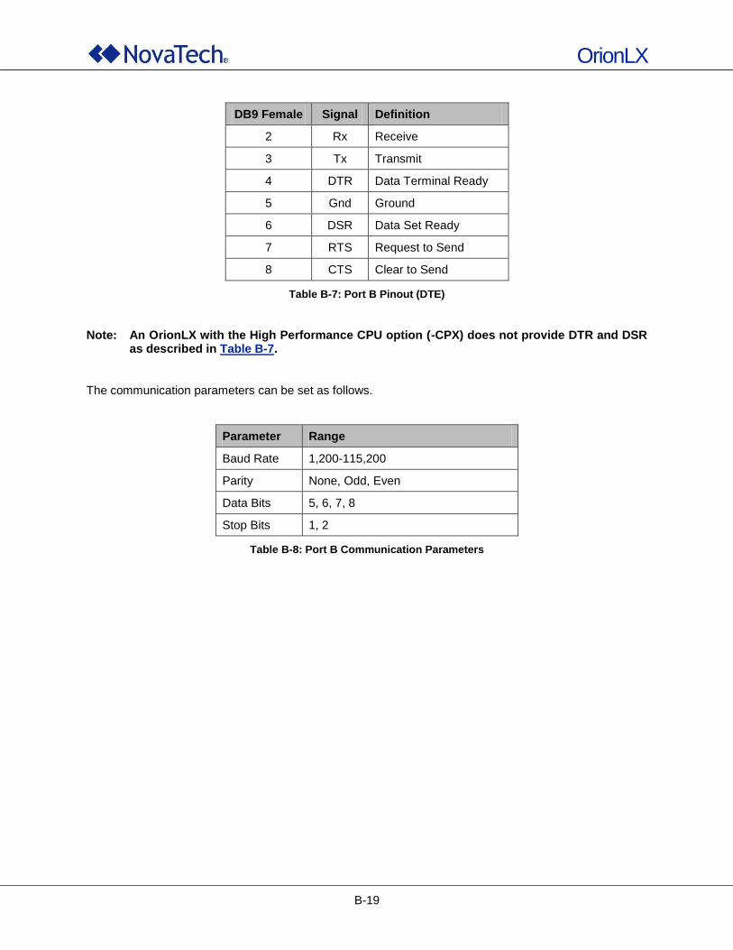
OrionLX
B-19
DB9 Female Signal Definition
2 Rx Receive
3 Tx Transmit
4 DTR Data Terminal Ready
5 Gnd Ground
6 DSR Data Set Ready
7 RTS Request to Send
8 CTS Clear to Send
Table B-7: Port B Pinout (DTE)
Note: An OrionLX with the High Performance CPU option (-CPX) does not provide DTR and DSR
as described in Table B-7. The communication parameters can be set as follows.
Parameter Range
Baud Rate 1,200-115,200
Parity None, Odd, Even
Data Bits 5, 6, 7, 8
Stop Bits 1, 2
Table B-8: Port B Communication Parameters

OrionLX
B-20
5. Digital Inputs The OrionLX has 4 digital inputs on the rear panel. These inputs use an orange compression screw terminal connector that accepts #12-24 gauge wire. The digital inputs are factory set to either 12-24 V dc or 48-125 V dc inputs as indicated by the checkbox positioned over the input connector. See Table B-10 for exact voltage ranges. The input circuitry provides 1000V channel-to-channel isolation. Inputs can be time stamped to 1ms when the OrionLX is receiving quality time synchronization.
Figure B-11: OrionLX Digital Input Connections
Function In4 + In4 - In3 + In3 - In2 + In2 - In1 + In1 -
Terminal 18 17 16 15 14 13 12 11
Table B-9: Digital Input Terminal Header
Input Range Turn-On Voltage Max. Current Drain
12/24V 9-36V 2.1 mA per input
48/125V 36-150V 2.1 mA per input
Table B-10: Digital Input Turn On Voltages and Current Draw
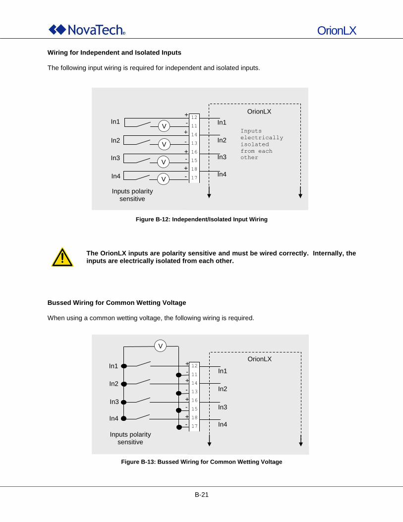
OrionLX
B-21
Wiring for Independent and Isolated Inputs The following input wiring is required for independent and isolated inputs.
Figure B-12: Independent/Isolated Input Wiring
The OrionLX inputs are polarity sensitive and must be wired correctly. Internally, the inputs are electrically isolated from each other.
Bussed Wiring for Common Wetting Voltage When using a common wetting voltage, the following wiring is required.
Figure B-13: Bussed Wiring for Common Wetting Voltage
Circuit Diagram – SER Model
Connections for independent inputs
12
11
14
13
16
15
18
17
In2
In3
In4
In1 V
V
V
V
In1
In2
In3
In4
Inputs
electrically
isolated
from each
other
Inputs polarity sensitive
+
+
+
+
-
-
-
-
OrionLX
12
11
14
13
16
15
18
17
In2
In3
In4
In1 In1
In2
In3
In4
V
Inputs polarity sensitive
+
+
+
+
-
-
-
-
OrionLX
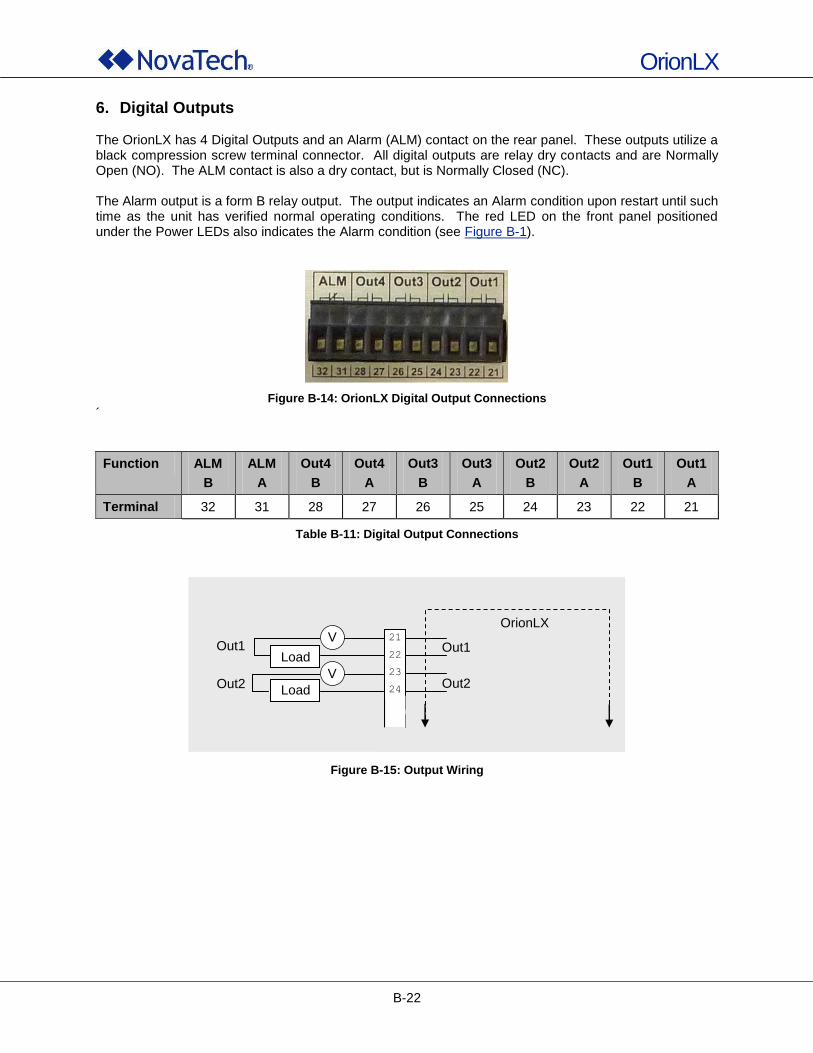
OrionLX
B-22
6. Digital Outputs The OrionLX has 4 Digital Outputs and an Alarm (ALM) contact on the rear panel. These outputs utilize a black compression screw terminal connector. All digital outputs are relay dry contacts and are Normally Open (NO). The ALM contact is also a dry contact, but is Normally Closed (NC). The Alarm output is a form B relay output. The output indicates an Alarm condition upon restart until such time as the unit has verified normal operating conditions. The red LED on the front panel positioned under the Power LEDs also indicates the Alarm condition (see Figure B-1).
Figure B-14: OrionLX Digital Output Connections
´
Function ALM
B
ALM
A
Out4
B
Out4
A
Out3
B
Out3
A
Out2
B
Out2
A
Out1
B
Out1
A
Terminal 32 31 28 27 26 25 24 23 22 21
Table B-11: Digital Output Connections
Figure B-15: Output Wiring
Circuit Diagram – SER Model
Connections for independent inputs
21
22
23
24 Out2
Out1
V
V
Out1 In1 Out2
OrionLX
Load
Load
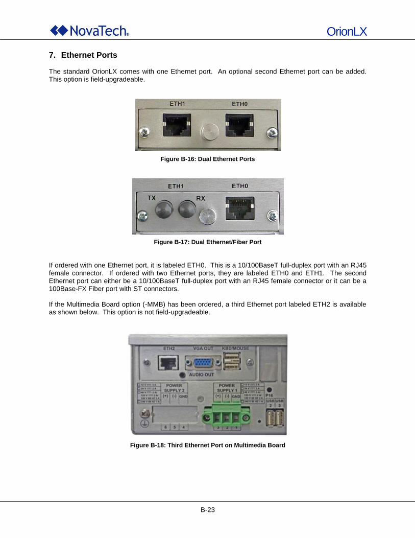
OrionLX
B-23
7. Ethernet Ports The standard OrionLX comes with one Ethernet port. An optional second Ethernet port can be added. This option is field-upgradeable.
Figure B-16: Dual Ethernet Ports
Figure B-17: Dual Ethernet/Fiber Port
If ordered with one Ethernet port, it is labeled ETH0. This is a 10/100BaseT full-duplex port with an RJ45 female connector. If ordered with two Ethernet ports, they are labeled ETH0 and ETH1. The second Ethernet port can either be a 10/100BaseT full-duplex port with an RJ45 female connector or it can be a 100Base-FX Fiber port with ST connectors. If the Multimedia Board option (-MMB) has been ordered, a third Ethernet port labeled ETH2 is available as shown below. This option is not field-upgradeable.
Figure B-18: Third Ethernet Port on Multimedia Board
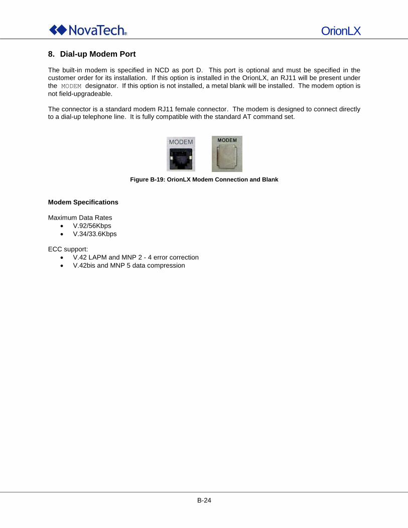
OrionLX
B-24
8. Dial-up Modem Port The built-in modem is specified in NCD as port D. This port is optional and must be specified in the customer order for its installation. If this option is installed in the OrionLX, an RJ11 will be present under
the MODEM designator. If this option is not installed, a metal blank will be installed. The modem option is
not field-upgradeable. The connector is a standard modem RJ11 female connector. The modem is designed to connect directly to a dial-up telephone line. It is fully compatible with the standard AT command set.
Figure B-19: OrionLX Modem Connection and Blank
Modem Specifications Maximum Data Rates
V.92/56Kbps
V.34/33.6Kbps
ECC support:
V.42 LAPM and MNP 2 - 4 error correction
V.42bis and MNP 5 data compression
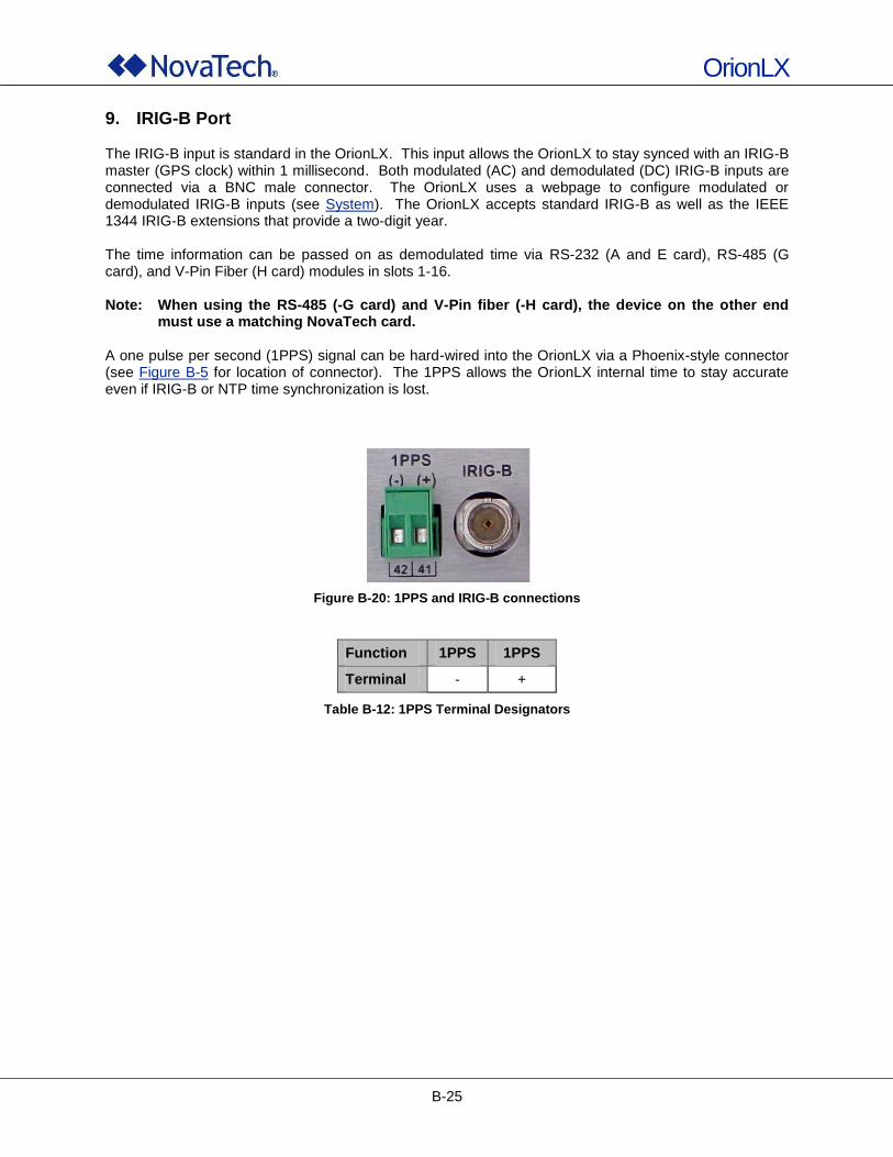
OrionLX
B-25
9. IRIG-B Port The IRIG-B input is standard in the OrionLX. This input allows the OrionLX to stay synced with an IRIG-B master (GPS clock) within 1 millisecond. Both modulated (AC) and demodulated (DC) IRIG-B inputs are connected via a BNC male connector. The OrionLX uses a webpage to configure modulated or demodulated IRIG-B inputs (see System). The OrionLX accepts standard IRIG-B as well as the IEEE 1344 IRIG-B extensions that provide a two-digit year. The time information can be passed on as demodulated time via RS-232 (A and E card), RS-485 (G card), and V-Pin Fiber (H card) modules in slots 1-16. Note: When using the RS-485 (-G card) and V-Pin fiber (-H card), the device on the other end
must use a matching NovaTech card. A one pulse per second (1PPS) signal can be hard-wired into the OrionLX via a Phoenix-style connector (see Figure B-5 for location of connector). The 1PPS allows the OrionLX internal time to stay accurate even if IRIG-B or NTP time synchronization is lost.
Figure B-20: 1PPS and IRIG-B connections
Function 1PPS 1PPS
Terminal - +
Table B-12: 1PPS Terminal Designators
OrionLX
B-26
10. Ports 1-16 Ports 1-16 are options ports that can consist of any combination of the following. Each module is followed by its part number. The part number is always post-fixed with nn, where nn is the number of modules of this type in the OrionLX, for a maximum of 16 modules. For example, –A11 –D02 –G03 indicates eleven standard RS-232 modules, two bit cards, and three RS-485 modules with IRIG-B.
RS-232 Serial Card (Standard/Type –A and Isolated/Type –E Version)
Isolated RS-485/422 Serial Card (Type –B)
ST Fiber Serial Card (Type –C)
Isolated Bit Protocol Card (Type –D)
Isolated RS-485 Serial Card with IRIG-B (Type –G)
V-Pin HCS Fiber Serial Card (Type –H)
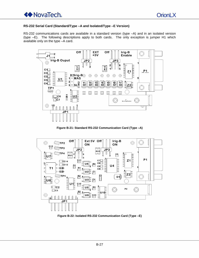
OrionLX
B-27
RS-232 Serial Card (Standard/Type –A and Isolated/Type –E Version) RS-232 communications cards are available in a standard version (type –A) and in an isolated version (type –E). The following descriptions apply to both cards. The only exception is jumper H1 which available only on the type –A card.
Figure B-21: Standard RS-232 Communication Card (Type –A)
Figure B-22: Isolated RS-232 Communication Card (Type –E)
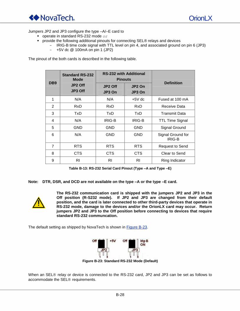
OrionLX
B-28
Jumpers JP2 and JP3 configure the type –A/–E card to
operate in standard RS-232 mode or
provide the following additional pinouts for connecting SEL® relays and devices IRIG-B time code signal with TTL level on pin 4, and associated ground on pin 6 (JP3) +5V dc @ 100mA on pin 1 (JP2)
The pinout of the both cards is described in the following table.
DB9
Standard RS-232 Mode
JP2 Off
JP3 Off
RS-232 with Additional
Pinouts Definition
JP2 Off
JP3 On
JP2 On
JP3 On
1 N/A N/A +5V dc Fused at 100 mA
2 RxD RxD RxD Receive Data
3 TxD TxD TxD Transmit Data
4 N/A IRIG-B IRIG-B TTL Time Signal
5 GND GND GND Signal Ground
6 N/A GND GND Signal Ground for IRIG-B
7 RTS RTS RTS Request to Send
8 CTS CTS CTS Clear to Send
9 RI RI RI Ring Indicator
Table B-13: RS-232 Serial Card Pinout (Type –A and Type –E)
Note: DTR, DSR, and DCD are not available on the type –A or the type –E card.
The RS-232 communication card is shipped with the jumpers JP2 and JP3 in the Off position (R-S232 mode). If JP2 and JP3 are changed from their default position, and the card is later connected to other third-party devices that operate in RS-232 mode, damage to the devices and/or the OrionLX card may occur. Return jumpers JP2 and JP3 to the Off position before connecting to devices that require standard RS-232 communcation.
The default setting as shipped by NovaTech is shown in Figure B-23.
Figure B-23: Standard RS-232 Mode (Default)
When an SEL relay or device is connected to the RS-232 card, JP2 and JP3 can be set as follows to
accommodate the SEL requirements.
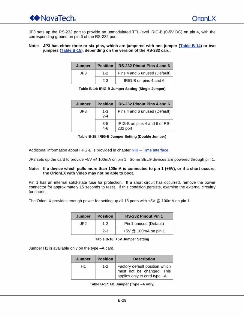
OrionLX
B-29
JP3 sets up the RS-232 port to provide an unmodulated TTL-level IRIG-B (0-5V DC) on pin 4, with the corresponding ground on pin 6 of the RS-232 port. Note: JP3 has either three or six pins, which are jumpered with one jumper (Table B-14) or two
jumpers (Table B-15), depending on the version of the RS-232 card.
Jumper Position RS-232 Pinout Pins 4 and 6
JP3 1-2 Pins 4 and 6 unused (Default)
2-3 IRIG-B on pins 4 and 6
Table B-14: IRIG-B Jumper Setting (Single Jumper)
Jumper Position RS-232 Pinout Pins 4 and 6
JP3 1-3
2-4
Pins 4 and 6 unused (Default)
3-5
4-6
IRIG-B on pins 4 and 6 of RS-
232 port
Table B-15: IRIG-B Jumper Setting (Double Jumper)
Additional information about IRIG-B is provided in chapter NKI – Time Interface. JP2 sets up the card to provide +5V @ 100mA on pin 1. Some SEL® devices are powered through pin 1. Note: If a device which pulls more than 100mA is connected to pin 1 (+5V), or if a short occurs,
the OrionLX with Video may not be able to boot. Pin 1 has an internal solid-state fuse for protection. If a short circuit has occurred, remove the power connector for approximately 15 seconds to reset. If this condition persists, examine the external circuitry for shorts. The OrionLX provides enough power for setting up all 16 ports with +5V @ 100mA on pin 1.
Jumper Position RS-232 Pinout Pin 1
JP2 1-2 Pin 1 unused (Default)
2-3 +5V @ 100mA on pin 1
Table B-16: +5V Jumper Setting
Jumper H1 is available only on the type –A card.
Jumper Position Description
H1 1-2 Factory default position which
must not be changed. This
applies only to card type –A.
Table B-17: H1 Jumper (Type –A only)
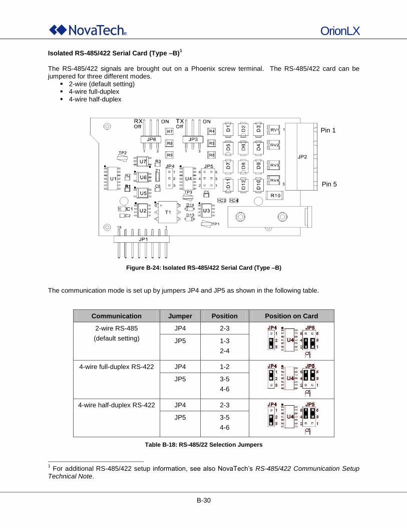
OrionLX
B-30
Isolated RS-485/422 Serial Card (Type –B)1
The RS-485/422 signals are brought out on a Phoenix screw terminal. The RS-485/422 card can be jumpered for three different modes.
2-wire (default setting) 4-wire full-duplex 4-wire half-duplex
Figure B-24: Isolated RS-485/422 Serial Card (Type –B)
The communication mode is set up by jumpers JP4 and JP5 as shown in the following table.
Communication Jumper Position Position on Card
2-wire RS-485
(default setting)
JP4 2-3
JP5 1-3
2-4
4-wire full-duplex RS-422 JP4 1-2
JP5 3-5
4-6
4-wire half-duplex RS-422 JP4 2-3
JP5 3-5
4-6
Table B-18: RS-485/22 Selection Jumpers
1 For additional RS-485/422 setup information, see also NovaTech‟s RS-485/422 Communication Setup
Technical Note.
Pin 5
Pin 1
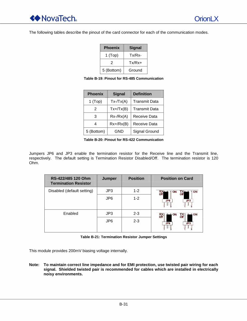
OrionLX
B-31
The following tables describe the pinout of the card connector for each of the communication modes.
Phoenix Signal
1 (Top) Tx/Rx-
2 Tx/Rx+
5 (Bottom) Ground
Table B-19: Pinout for RS-485 Communication
Phoenix Signal Definition
1 (Top) Tx-/Tx(A) Transmit Data
2 Tx+/Tx(B) Transmit Data
3 Rx-/Rx(A) Receive Data
4 Rx+/Rx(B) Receive Data
5 (Bottom) GND Signal Ground
Table B-20: Pinout for RS-422 Communication
Jumpers JP6 and JP3 enable the termination resistor for the Receive line and the Transmit line, respectively. The default setting is Termination Resistor Disabled/Off. The termination resistor is 120 Ohm.
RS-422/485 120 Ohm
Termination Resistor
Jumper Position Position on Card
Disabled (default setting) JP3 1-2
JP6 1-2
Enabled JP3 2-3
JP6 2-3
Table B-21: Termination Resistor Jumper Settings
This module provides 200mV biasing voltage internally. Note: To maintain correct line impedance and for EMI protection, use twisted pair wiring for each
signal. Shielded twisted pair is recommended for cables which are installed in electrically noisy environments.
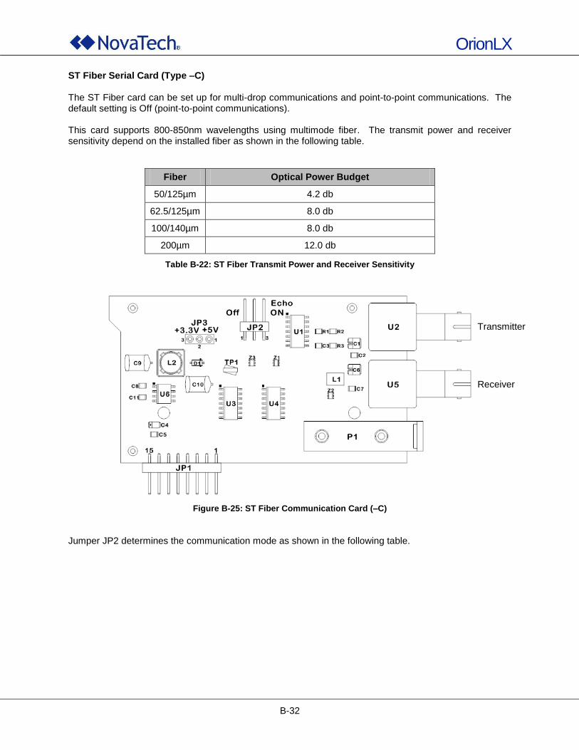
OrionLX
B-32
ST Fiber Serial Card (Type –C) The ST Fiber card can be set up for multi-drop communications and point-to-point communications. The default setting is Off (point-to-point communications). This card supports 800-850nm wavelengths using multimode fiber. The transmit power and receiver sensitivity depend on the installed fiber as shown in the following table.
Fiber Optical Power Budget
50/125µm 4.2 db
62.5/125µm 8.0 db
100/140µm 8.0 db
200µm 12.0 db
Table B-22: ST Fiber Transmit Power and Receiver Sensitivity
Figure B-25: ST Fiber Communication Card (–C)
Jumper JP2 determines the communication mode as shown in the following table.
Transmitter
Receiver
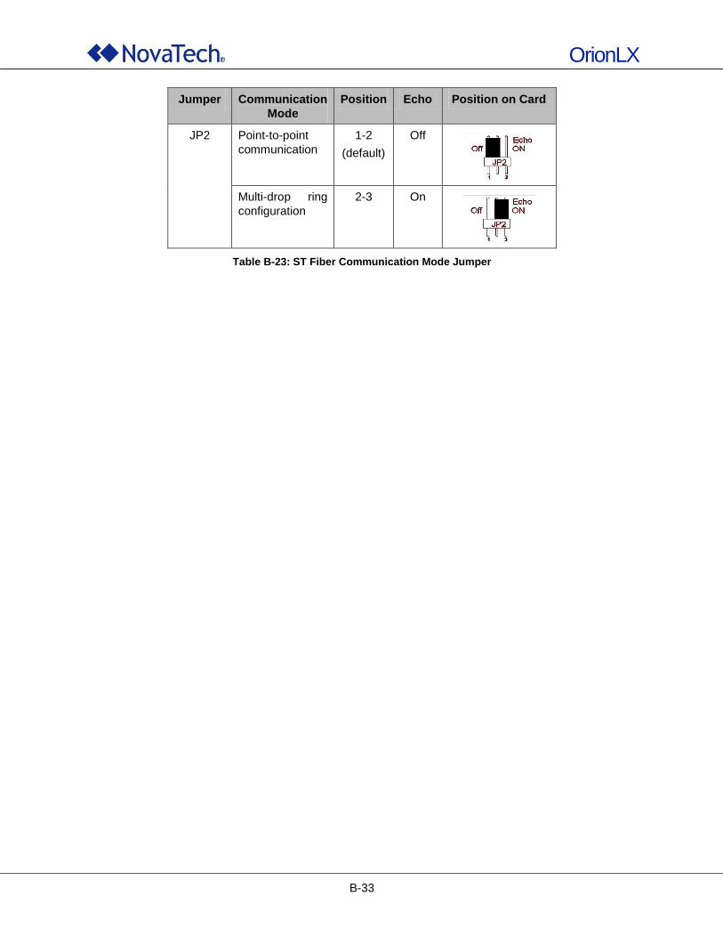
OrionLX
B-33
Jumper Communication
Mode
Position Echo Position on Card
JP2 Point-to-point
communication
1-2
(default)
Off
Multi-drop ring
configuration
2-3 On
Table B-23: ST Fiber Communication Mode Jumper
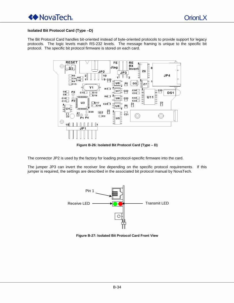
OrionLX
B-34
Isolated Bit Protocol Card (Type –D) The Bit Protocol Card handles bit-oriented instead of byte-oriented protocols to provide support for legacy protocols. The logic levels match RS-232 levels. The message framing is unique to the specific bit protocol. The specific bit protocol firmware is stored on each card.
Figure B-26: Isolated Bit Protocol Card (Type – D)
The connector JP2 is used by the factory for loading protocol-specific firmware into the card. The jumper JP3 can invert the receiver line depending on the specific protocol requirements. If this jumper is required, the settings are described in the associated bit protocol manual by NovaTech.
Figure B-27: Isolated Bit Protocol Card Front View
Pin 1
Receive LED Transmit LED
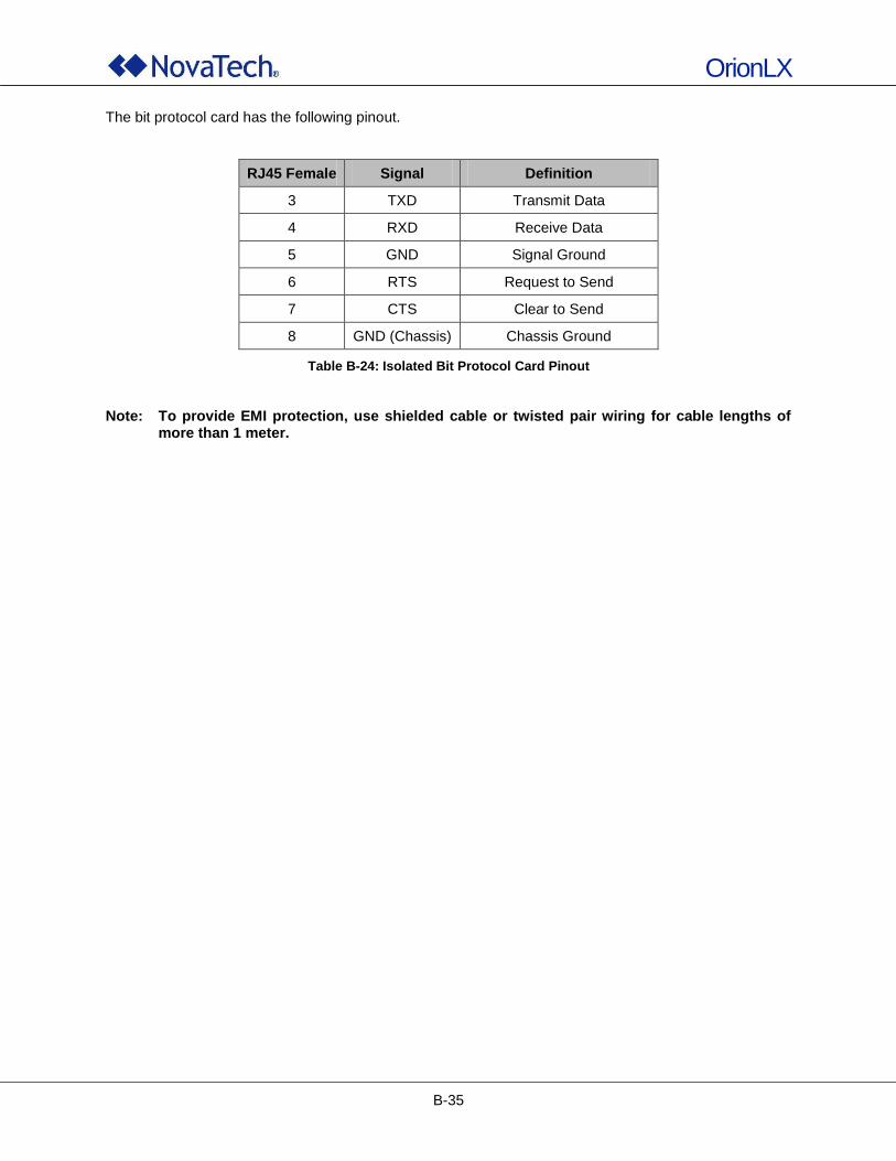
OrionLX
B-35
The bit protocol card has the following pinout.
RJ45 Female Signal Definition
3 TXD Transmit Data
4 RXD Receive Data
5 GND Signal Ground
6 RTS Request to Send
7 CTS Clear to Send
8 GND (Chassis) Chassis Ground
Table B-24: Isolated Bit Protocol Card Pinout
Note: To provide EMI protection, use shielded cable or twisted pair wiring for cable lengths of
more than 1 meter.
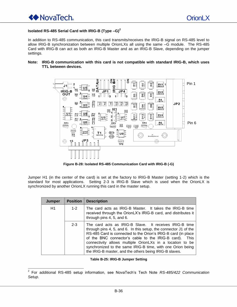
OrionLX
B-36
Isolated RS-485 Serial Card with IRIG-B (Type –G)2
In addition to RS-485 communication, this card transmits/receives the IRIG-B signal on RS-485 level to allow IRIG-B synchronization between multiple OrionLXs all using the same –G module. The RS-485 Card with IRIG-B can act as both an IRIG-B Master and as an IRIG-B Slave, depending on the jumper settings. Note: IRIG-B communication with this card is not compatible with standard IRIG-B, which uses
TTL between devices.
Figure B-28: Isolated RS-485 Communication Card with IRIG-B (-G)
Jumper H1 (in the center of the card) is set at the factory to IRIG-B Master (setting 1-2) which is the standard for most applications. Setting 2-3 is IRIG-B Slave which is used when the OrionLX is synchronized by another OrionLX running this card in the master setup.
Jumper Position Description
H1 1-2 The card acts as IRIG-B Master. It takes the IRIG-B time
received through the OrionLX‟s IRIG-B card, and distributes it
through pins 4, 5, and 6.
2-3 The card acts as IRIG-B Slave. It receives IRIG-B time through pins 4, 5, and 6. In this setup, the connector J1 of the RS-485 Card is connected to the Orion‟s IRIG-B card (in place of the BNC connector‟s cable to the IRIG-B card). This connectivity allows multiple OrionLXs in a location to be synchronized to the same IRIG-B time, with one Orion being the IRIG-B master, and the others being IRIG-B slaves.
Table B-25: IRIG-B Jumper Setting
2 For additional RS-485 setup information, see NovaTech‟s Tech Note RS-485/422 Communication
Setup.
Pin 1
Pin 6
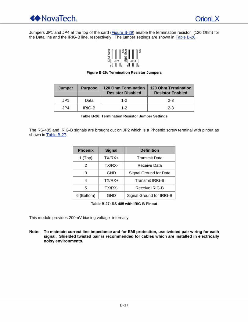
OrionLX
B-37
Jumpers JP1 and JP4 at the top of the card (Figure B-29) enable the termination resistor (120 Ohm) for the Data line and the IRIG-B line, respectively. The jumper settings are shown in Table B-26.
Figure B-29: Termination Resistor Jumpers
Jumper Purpose 120 Ohm Termination
Resistor Disabled
120 Ohm Termination
Resistor Enabled
JP1 Data 1-2 2-3
JP4 IRIG-B 1-2 2-3
Table B-26: Termination Resistor Jumper Settings
The RS-485 and IRIG-B signals are brought out on JP2 which is a Phoenix screw terminal with pinout as shown in Table B-27.
Phoenix Signal Definition
1 (Top) TX/RX+ Transmit Data
2 TX/RX- Receive Data
3 GND Signal Ground for Data
4 TX/RX+ Transmit IRIG-B
5 TX/RX- Receive IRIG-B
6 (Bottom) GND Signal Ground for IRIG-B
Table B-27: RS-485 with IRIG-B Pinout
This module provides 200mV biasing voltage internally. Note: To maintain correct line impedance and for EMI protection, use twisted pair wiring for each
signal. Shielded twisted pair is recommended for cables which are installed in electrically noisy environments.
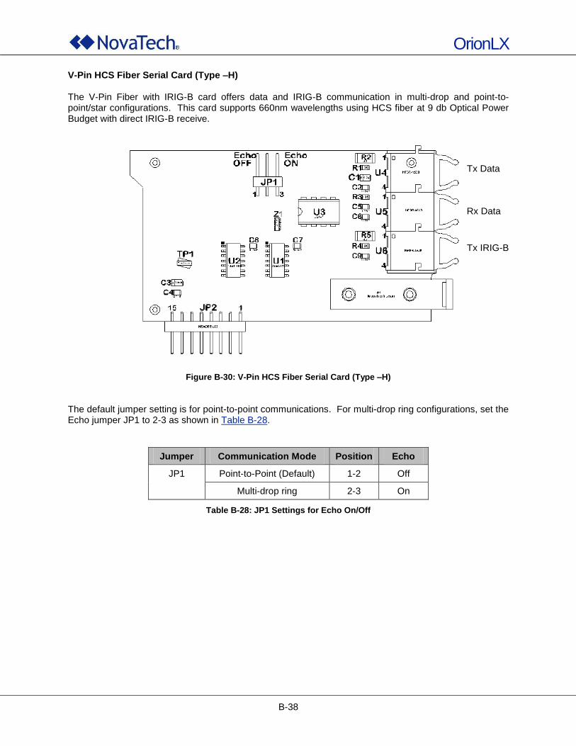
OrionLX
B-38
V-Pin HCS Fiber Serial Card (Type –H) The V-Pin Fiber with IRIG-B card offers data and IRIG-B communication in multi-drop and point-to-point/star configurations. This card supports 660nm wavelengths using HCS fiber at 9 db Optical Power Budget with direct IRIG-B receive.
Figure B-30: V-Pin HCS Fiber Serial Card (Type –H)
The default jumper setting is for point-to-point communications. For multi-drop ring configurations, set the Echo jumper JP1 to 2-3 as shown in Table B-28.
Jumper Communication Mode Position Echo
JP1 Point-to-Point (Default) 1-2 Off
Multi-drop ring 2-3 On
Table B-28: JP1 Settings for Echo On/Off
Tx Data
Rx Data
Tx IRIG-B
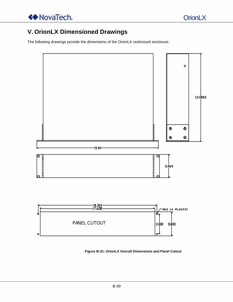
OrionLX
B-39
V. OrionLX Dimensioned Drawings The following drawings provide the dimensions of the OrionLX rackmount enclosure.
Figure B-31: OrionLX Overall Dimensions and Panel Cutout
PANEL CUTOUT
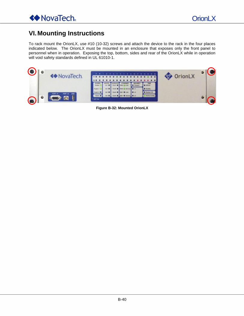
OrionLX
B-40
VI. Mounting Instructions To rack mount the OrionLX, use #10 (10-32) screws and attach the device to the rack in the four places indicated below. The OrionLX must be mounted in an enclosure that exposes only the front panel to personnel when in operation. Exposing the top, bottom, sides and rear of the OrionLX while in operation will void safety standards defined in UL 61010-1.
Figure B-32: Mounted OrionLX

OrionLX
B-41
VII. Fuse Replacement On the OrionLX, power supply fuses and surge board fuses can be replaced as follows.
Removing the top cover of the OrionLX exposes the technician to live voltage. Proper care must be taken by either removing the power to the OrionLX prior to removing the top cover, or by using proper equipment and tools to protect against electric shock. Failure to do so could result in equipment damage, injury, and/or death.
When removing the top cover of the OrionLX, observe precautions for handling electrostatic sensitive devices.
The power supply fuses are accessible by removing the top cover of the OrionLX.
1. Replacing Power Supply Surge Board Fuses The fuses of the power supply surge board (board number 750-106) depend on the input voltages of the OrionLX power supplies. The surge board is located inside the OrionLX enclosure at the power supply connectors (see Figure B-5 and Figure B-6) and shown in the following figures.
Figure B-33: Power Supply Board Fuses, Board Revisions B-D
Fusing is available starting at revision B of the power supply board (750-106). The 5x20mm fuses must be installed as shown in Figure B-33.
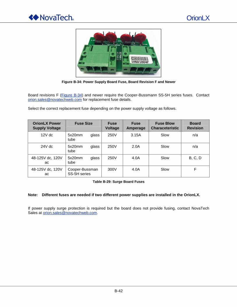
OrionLX
B-42
Figure B-34: Power Supply Board Fuse, Board Revision F and Newer
Board revisions F (Figure B-34) and newer require the Cooper-Bussmann SS-5H series fuses. Contact [email protected] for replacement fuse details. Select the correct replacement fuse depending on the power supply voltage as follows.
OrionLX Power
Supply Voltage
Fuse Size Fuse
Voltage
Fuse
Amperage
Fuse Blow
Characeteristic
Board
Revision
12V dc 5x20mm glass tube
250V 3.15A Slow n/a
24V dc 5x20mm glass tube
250V 2.0A Slow n/a
48-125V dc, 120V ac
5x20mm glass tube
250V 4.0A Slow B, C, D
48-125V dc, 120V ac
Cooper-Bussman SS-5H series
300V 4.0A Slow F
Table B-29: Surge Board Fuses
Note: Different fuses are needed if two different power supplies are installed in the OrionLX. If power supply surge protection is required but the board does not provide fusing, contact NovaTech Sales at [email protected].

OrionLX
C-1
C. NovaTech Configuration Director (NCD)

OrionLX
C-2
I. Introduction to NovaTech Configuration Director (NCD)
1. Purpose of NCD NCD is Windows
®-based configuration software with a practical and straightforward graphic user interface
(GUI) that does not require special programming or scripting. Communications are easily set up between the OrionLX and a protocol master, Human Machine Interface (HMI), Programmable Logic Controller (PLC), or an Intelligent Electronic Device (IED) such as a relay or a meter. For many slave devices (i.e. devices being polled by the OrionLX), default files are available that contain the device‟s standard input and output points with name, point address, and range. This further facilitates fast setup of the OrionLX. NCD is used to set up the following features of an OrionLX configuration. The setup of other features not listed here is described in section OrionLX Webpage.
Serial and IP Port Setup Input/Output Point Lists for each Master and Slave Port Allow Forcing of Input/Output Points for Commissioning and Troubleshooting Add On Features:
Alarm/Archive/Retentive Alias Data Logger Orion LEDs Points Blocking Pseudo Master Pusher Slave System Logger Text Module
Hardware Sensor SER Input/Output Points Logic or LogicPak
Once the Orion‟s configuration has been created off-line and saved to an .ncd file, the .ncd file must be transferred from the PC to the Orion in one of the following ways:
Serial connection between the PC running NCD and the OrionLX. Option File Transfer (PC -> ORION) of the Orion‟s MMI transfers the .ncd configuration file to the Orion.
Ethernet connection between the PC running NCD and the Orion. Before the first time a file is transferred using the OrionLX‟s web interface, the OrionLX‟s IP address must be set through the OrionLX‟s serial port
3 as described in Network Menu. Then the web browser can access the
OrionLX‟s webpage. After logging in on the webpage, the .ncd configuration file can be transferred to the OrionLX as described in User Files.
In addition to the configuration options, NCD provides a built-in terminal window for viewing of data values, port communications, device statistics, system events, and system/version information. It also allows firmware file and log file transfers via Z-Modem (bi-directional), as well as passthrough to connected relays and meters. This allows using the respective manufacturer‟s programming software to configure the relays and meters, retrieve event information, etc. Section OrionLX MMI provides a full explanation of these features.
3 For all Orion models, the MMI port is a female DTE port labeled Port A which is located on the front
panel. The fixed communication parameters are 115200 baud, no parity, 8 data bits, and 1 stop bit.
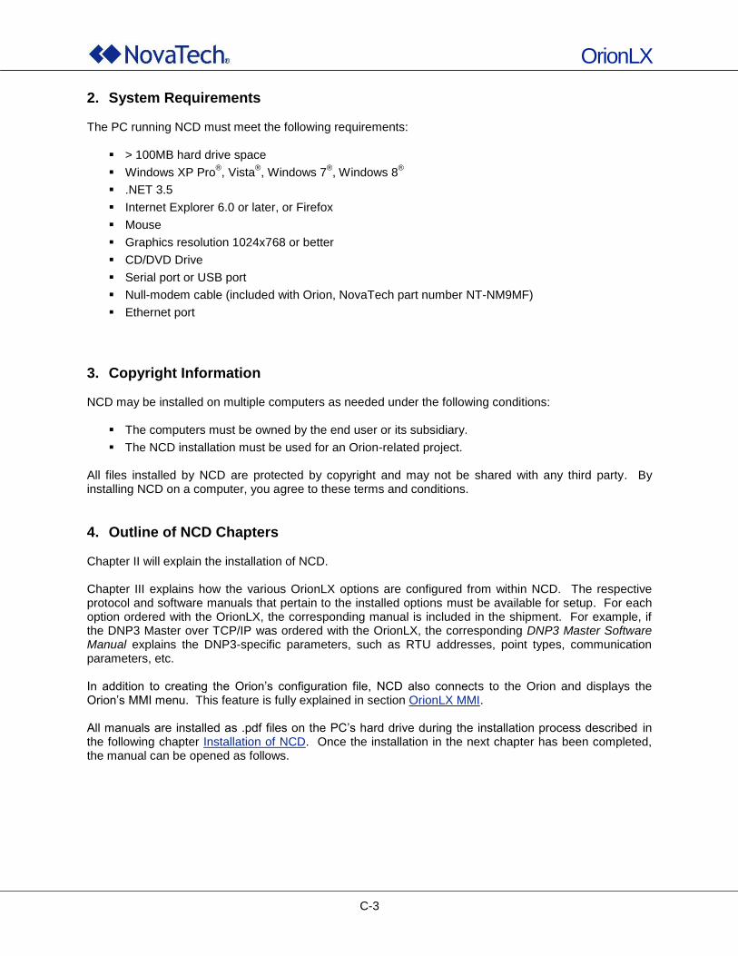
OrionLX
C-3
2. System Requirements The PC running NCD must meet the following requirements:
> 100MB hard drive space
Windows XP Pro®, Vista
®, Windows 7
®, Windows 8
®
.NET 3.5
Internet Explorer 6.0 or later, or Firefox
Mouse
Graphics resolution 1024x768 or better
CD/DVD Drive
Serial port or USB port
Null-modem cable (included with Orion, NovaTech part number NT-NM9MF)
Ethernet port
3. Copyright Information NCD may be installed on multiple computers as needed under the following conditions:
The computers must be owned by the end user or its subsidiary.
The NCD installation must be used for an Orion-related project. All files installed by NCD are protected by copyright and may not be shared with any third party. By installing NCD on a computer, you agree to these terms and conditions.
4. Outline of NCD Chapters Chapter II will explain the installation of NCD. Chapter III explains how the various OrionLX options are configured from within NCD. The respective protocol and software manuals that pertain to the installed options must be available for setup. For each option ordered with the OrionLX, the corresponding manual is included in the shipment. For example, if the DNP3 Master over TCP/IP was ordered with the OrionLX, the corresponding DNP3 Master Software Manual explains the DNP3-specific parameters, such as RTU addresses, point types, communication parameters, etc. In addition to creating the Orion‟s configuration file, NCD also connects to the Orion and displays the Orion‟s MMI menu. This feature is fully explained in section OrionLX MMI. All manuals are installed as .pdf files on the PC‟s hard drive during the installation process described in the following chapter Installation of NCD. Once the installation in the next chapter has been completed, the manual can be opened as follows.
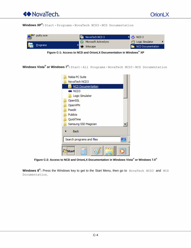
OrionLX
C-4
Windows XP®: Start - Programs - NovaTech NCD3 - NCD Documentation
Figure C-1: Access to NCD and OrionLX Documentation in Windows® XP
Windows Vista® or Windows 7
®: Start - All Programs - NovaTech NCD3 - NCD Documentation
Figure C-2: Access to NCD and OrionLX Documentation in Windows Vista® or Windows 7.0
®
Windows 8®: Press the Windows key to get to the Start Menu, then go to NovaTech NCD3 and NCD
Documentation.
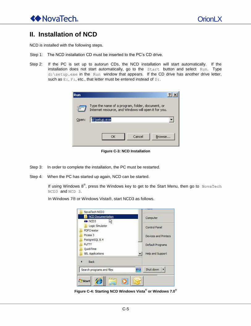
OrionLX
C-5
II. Installation of NCD NCD is installed with the following steps. Step 1: The NCD installation CD must be inserted to the PC‟s CD drive. Step 2: If the PC is set up to autorun CDs, the NCD installation will start automatically. If the
installation does not start automatically, go to the Start button and select Run. Type
d:\setup.exe in the Run window that appears. If the CD drive has another drive letter,
such as E:, F:, etc., that letter must be entered instead of D:.
Figure C-3: NCD Installation
Step 3: In order to complete the installation, the PC must be restarted. Step 4: When the PC has started up again, NCD can be started.
If using Windows 8®, press the Windows key to get to the Start Menu, then go to NovaTech
NCD3 and NCD 3.
In Windows 7® or Windows Vista®, start NCD3 as follows.
Figure C-4: Starting NCD Windows Vista® or Windows 7.0
®
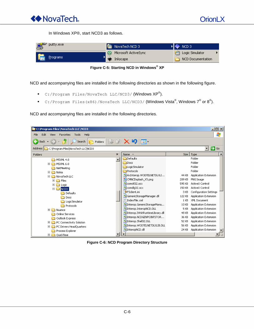
OrionLX
C-6
In Windows XP®, start NCD3 as follows.
Figure C-5: Starting NCD in Windows® XP
NCD and accompanying files are installed in the following directories as shown in the following figure.
C:/Program Files/NovaTech LLC/NCD3/ (Windows XP®).
C:/Program Files(x86)/NovaTech LLC/NCD3/ (Windows Vista®, Windows 7
® or 8
®).
NCD and accompanying files are installed in the following directories.
Figure C-6: NCD Program Directory Structure
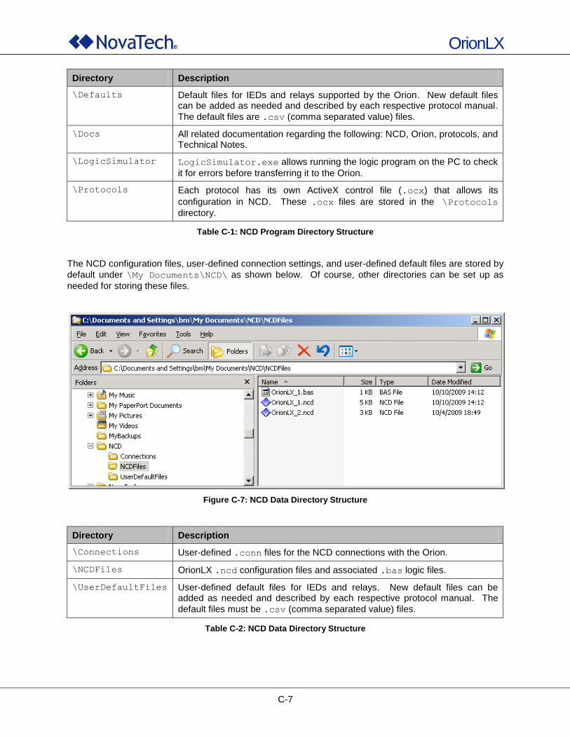
OrionLX
C-7
Directory Description
\Defaults Default files for IEDs and relays supported by the Orion. New default files can be added as needed and described by each respective protocol manual.
The default files are .csv (comma separated value) files.
\Docs All related documentation regarding the following: NCD, Orion, protocols, and Technical Notes.
\LogicSimulator LogicSimulator.exe allows running the logic program on the PC to check
it for errors before transferring it to the Orion.
\Protocols Each protocol has its own ActiveX control file (.ocx) that allows its
configuration in NCD. These .ocx files are stored in the \Protocols
directory.
Table C-1: NCD Program Directory Structure
The NCD configuration files, user-defined connection settings, and user-defined default files are stored by
default under \My Documents\NCD\ as shown below. Of course, other directories can be set up as
needed for storing these files.
Figure C-7: NCD Data Directory Structure
Directory Description
\Connections User-defined .conn files for the NCD connections with the Orion.
\NCDFiles OrionLX .ncd configuration files and associated .bas logic files.
\UserDefaultFiles User-defined default files for IEDs and relays. New default files can be added as needed and described by each respective protocol manual. The
default files must be .csv (comma separated value) files.
Table C-2: NCD Data Directory Structure
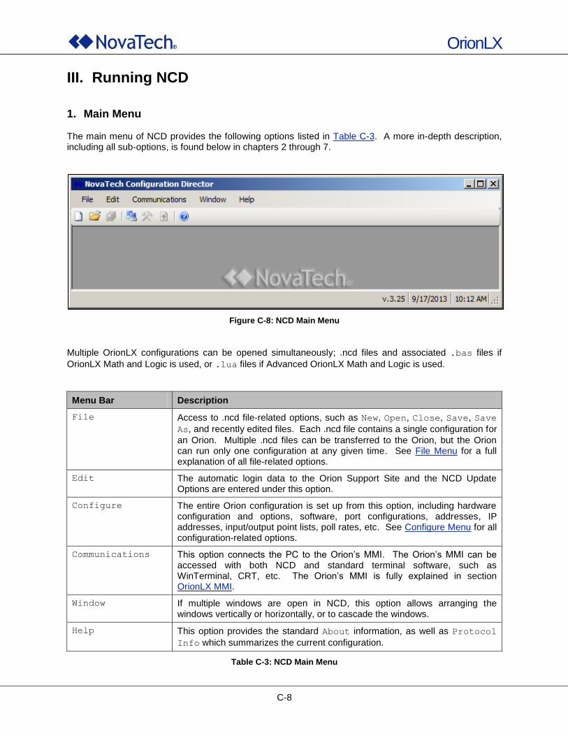
OrionLX
C-8
III. Running NCD
1. Main Menu The main menu of NCD provides the following options listed in Table C-3. A more in-depth description, including all sub-options, is found below in chapters 2 through 7.
Figure C-8: NCD Main Menu
Multiple OrionLX configurations can be opened simultaneously; .ncd files and associated .bas files if
OrionLX Math and Logic is used, or .lua files if Advanced OrionLX Math and Logic is used.
Menu Bar Description
File Access to .ncd file-related options, such as New, Open, Close, Save, Save
As, and recently edited files. Each .ncd file contains a single configuration for
an Orion. Multiple .ncd files can be transferred to the Orion, but the Orion can run only one configuration at any given time. See File Menu for a full explanation of all file-related options.
Edit The automatic login data to the Orion Support Site and the NCD Update Options are entered under this option.
Configure The entire Orion configuration is set up from this option, including hardware configuration and options, software, port configurations, addresses, IP addresses, input/output point lists, poll rates, etc. See Configure Menu for all configuration-related options.
Communications This option connects the PC to the Orion‟s MMI. The Orion‟s MMI can be accessed with both NCD and standard terminal software, such as WinTerminal, CRT, etc. The Orion‟s MMI is fully explained in section OrionLX MMI.
Window If multiple windows are open in NCD, this option allows arranging the windows vertically or horizontally, or to cascade the windows.
Help This option provides the standard About information, as well as Protocol
Info which summarizes the current configuration.
Table C-3: NCD Main Menu
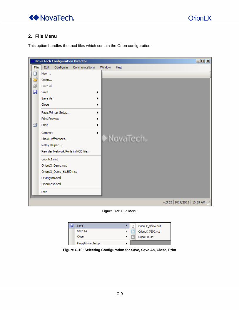
OrionLX
C-9
2. File Menu This option handles the .ncd files which contain the Orion configuration.
Figure C-9: File Menu
Figure C-10: Selecting Configuration for Save, Save As, Close, Print
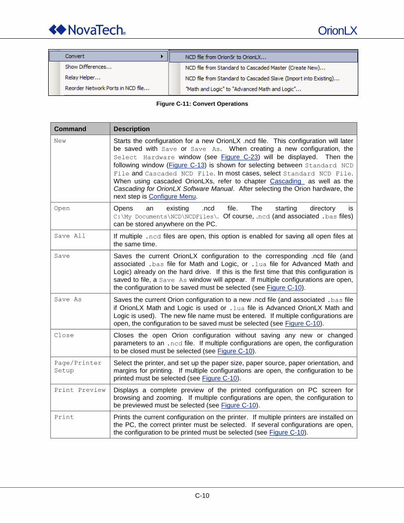
OrionLX
C-10
Figure C-11: Convert Operations
Command Description
New Starts the configuration for a new OrionLX .ncd file. This configuration will later
be saved with Save or Save As. When creating a new configuration, the
Select Hardware window (see Figure C-23) will be displayed. Then the
following window (Figure C-13) is shown for selecting between Standard NCD
File and Cascaded NCD File. In most cases, select Standard NCD File.
When using cascaded OrionLXs, refer to chapter Cascading as well as the Cascading for OrionLX Software Manual. After selecting the Orion hardware, the next step is Configure Menu.
Open Opens an existing .ncd file. The starting directory is
C:\My Documents\NCD\NCDFiles\. Of course, .ncd (and associated .bas files)
can be stored anywhere on the PC.
Save All If multiple .ncd files are open, this option is enabled for saving all open files at
the same time.
Save Saves the current OrionLX configuration to the corresponding .ncd file (and
associated .bas file for Math and Logic, or .lua file for Advanced Math and
Logic) already on the hard drive. If this is the first time that this configuration is
saved to file, a Save As window will appear. If multiple configurations are open,
the configuration to be saved must be selected (see Figure C-10).
Save As Saves the current Orion configuration to a new .ncd file (and associated .bas file
if OrionLX Math and Logic is used or .lua file is Advanced OrionLX Math and
Logic is used). The new file name must be entered. If multiple configurations are open, the configuration to be saved must be selected (see Figure C-10).
Close Closes the open Orion configuration without saving any new or changed
parameters to an .ncd file. If multiple configurations are open, the configuration
to be closed must be selected (see Figure C-10).
Page/Printer
Setup Select the printer, and set up the paper size, paper source, paper orientation, and margins for printing. If multiple configurations are open, the configuration to be printed must be selected (see Figure C-10).
Print Preview Displays a complete preview of the printed configuration on PC screen for browsing and zooming. If multiple configurations are open, the configuration to be previewed must be selected (see Figure C-10).
Print Prints the current configuration on the printer. If multiple printers are installed on the PC, the correct printer must be selected. If several configurations are open, the configuration to be printed must be selected (see Figure C-10).
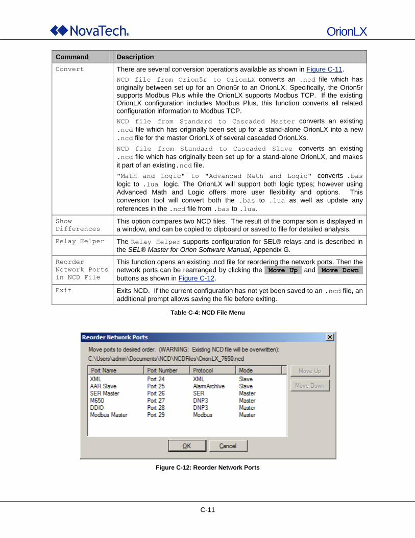
OrionLX
C-11
Command Description
Convert There are several conversion operations available as shown in Figure C-11.
NCD file from Orion5r to OrionLX converts an .ncd file which has
originally between set up for an Orion5r to an OrionLX. Specifically, the Orion5r supports Modbus Plus while the OrionLX supports Modbus TCP. If the existing OrionLX configuration includes Modbus Plus, this function converts all related configuration information to Modbus TCP.
NCD file from Standard to Cascaded Master converts an existing
.ncd file which has originally been set up for a stand-alone OrionLX into a new
.ncd file for the master OrionLX of several cascaded OrionLXs.
NCD file from Standard to Cascaded Slave converts an existing
.ncd file which has originally been set up for a stand-alone OrionLX, and makes
it part of an existing.ncd file.
"Math and Logic" to "Advanced Math and Logic" converts .bas
logic to .lua logic. The OrionLX will support both logic types; however using
Advanced Math and Logic offers more user flexibility and options. This
conversion tool will convert both the .bas to .lua as well as update any
references in the .ncd file from .bas to .lua.
Show
Differences This option compares two NCD files. The result of the comparison is displayed in a window, and can be copied to clipboard or saved to file for detailed analysis.
Relay Helper The Relay Helper supports configuration for SEL® relays and is described in
the SEL® Master for Orion Software Manual, Appendix G.
Reorder
Network Ports
in NCD File
This function opens an existing .ncd file for reordering the network ports. Then the network ports can be rearranged by clicking the Move Up and Move Down
buttons as shown in Figure C-12.
Exit Exits NCD. If the current configuration has not yet been saved to an .ncd file, an
additional prompt allows saving the file before exiting.
Table C-4: NCD File Menu
Figure C-12: Reorder Network Ports
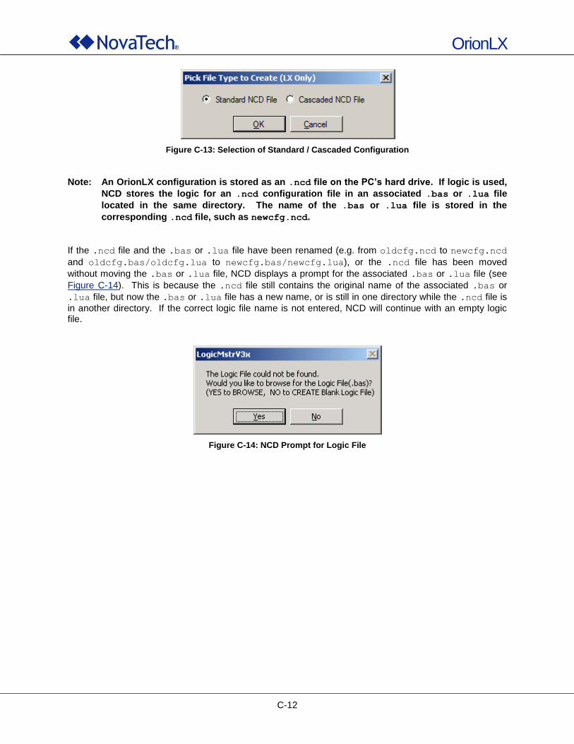
OrionLX
C-12
Figure C-13: Selection of Standard / Cascaded Configuration
Note: An OrionLX configuration is stored as an .ncd file on the PC’s hard drive. If logic is used,
NCD stores the logic for an .ncd configuration file in an associated .bas or .lua file
located in the same directory. The name of the .bas or .lua file is stored in the
corresponding .ncd file, such as newcfg.ncd.
If the .ncd file and the .bas or .lua file have been renamed (e.g. from oldcfg.ncd to newcfg.ncd
and oldcfg.bas/oldcfg.lua to newcfg.bas/newcfg.lua), or the .ncd file has been moved
without moving the .bas or .lua file, NCD displays a prompt for the associated .bas or .lua file (see
Figure C-14). This is because the .ncd file still contains the original name of the associated .bas or
.lua file, but now the .bas or .lua file has a new name, or is still in one directory while the .ncd file is
in another directory. If the correct logic file name is not entered, NCD will continue with an empty logic file.
Figure C-14: NCD Prompt for Logic File
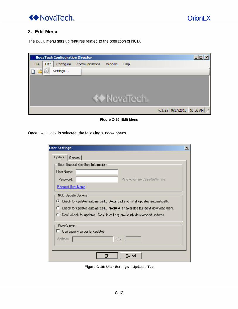
OrionLX
C-13
3. Edit Menu
The Edit menu sets up features related to the operation of NCD.
Figure C-15: Edit Menu
Once Settings is selected, the following window opens.
Figure C-16: User Settings – Updates Tab
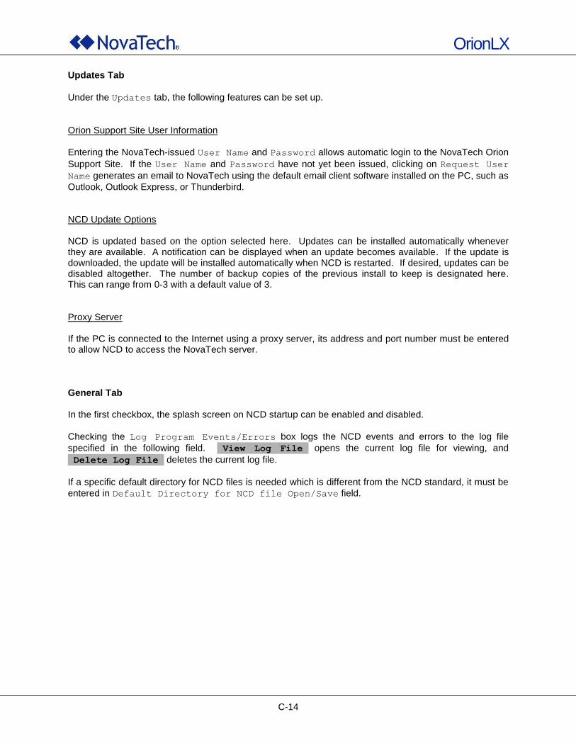
OrionLX
C-14
Updates Tab
Under the Updates tab, the following features can be set up.
Orion Support Site User Information
Entering the NovaTech-issued User Name and Password allows automatic login to the NovaTech Orion
Support Site. If the User Name and Password have not yet been issued, clicking on Request User
Name generates an email to NovaTech using the default email client software installed on the PC, such as
Outlook, Outlook Express, or Thunderbird. NCD Update Options NCD is updated based on the option selected here. Updates can be installed automatically whenever they are available. A notification can be displayed when an update becomes available. If the update is downloaded, the update will be installed automatically when NCD is restarted. If desired, updates can be disabled altogether. The number of backup copies of the previous install to keep is designated here. This can range from 0-3 with a default value of 3. Proxy Server If the PC is connected to the Internet using a proxy server, its address and port number must be entered to allow NCD to access the NovaTech server. General Tab In the first checkbox, the splash screen on NCD startup can be enabled and disabled.
Checking the Log Program Events/Errors box logs the NCD events and errors to the log file
specified in the following field. View Log File opens the current log file for viewing, and
Delete Log File deletes the current log file.
If a specific default directory for NCD files is needed which is different from the NCD standard, it must be
entered in Default Directory for NCD file Open/Save field.
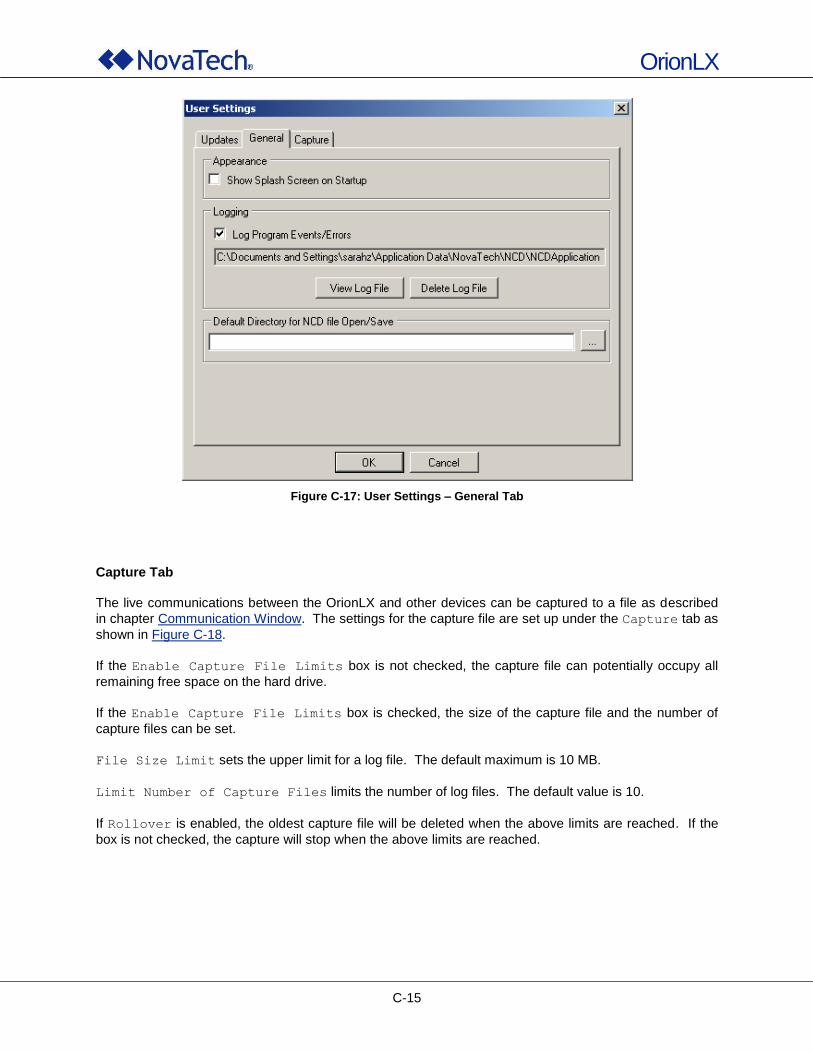
OrionLX
C-15
Figure C-17: User Settings – General Tab
Capture Tab The live communications between the OrionLX and other devices can be captured to a file as described
in chapter Communication Window. The settings for the capture file are set up under the Capture tab as
shown in Figure C-18.
If the Enable Capture File Limits box is not checked, the capture file can potentially occupy all
remaining free space on the hard drive.
If the Enable Capture File Limits box is checked, the size of the capture file and the number of
capture files can be set.
File Size Limit sets the upper limit for a log file. The default maximum is 10 MB.
Limit Number of Capture Files limits the number of log files. The default value is 10.
If Rollover is enabled, the oldest capture file will be deleted when the above limits are reached. If the
box is not checked, the capture will stop when the above limits are reached.
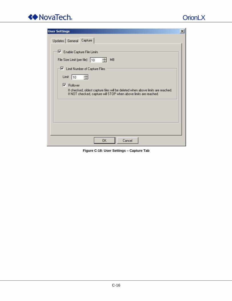
OrionLX
C-16
Figure C-18: User Settings – Capture Tab
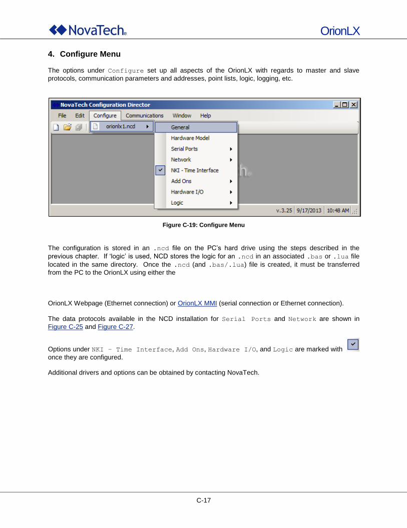
OrionLX
C-17
4. Configure Menu
The options under Configure set up all aspects of the OrionLX with regards to master and slave
protocols, communication parameters and addresses, point lists, logic, logging, etc.
Figure C-19: Configure Menu
The configuration is stored in an .ncd file on the PC‟s hard drive using the steps described in the
previous chapter. If „logic‟ is used, NCD stores the logic for an .ncd in an associated .bas or .lua file
located in the same directory. Once the .ncd (and .bas/.lua) file is created, it must be transferred
from the PC to the OrionLX using either the OrionLX Webpage (Ethernet connection) or OrionLX MMI (serial connection or Ethernet connection).
The data protocols available in the NCD installation for Serial Ports and Network are shown in
Figure C-25 and Figure C-27.
Options under NKI – Time Interface, Add Ons, Hardware I/O, and Logic are marked with
once they are configured. Additional drivers and options can be obtained by contacting NovaTech.
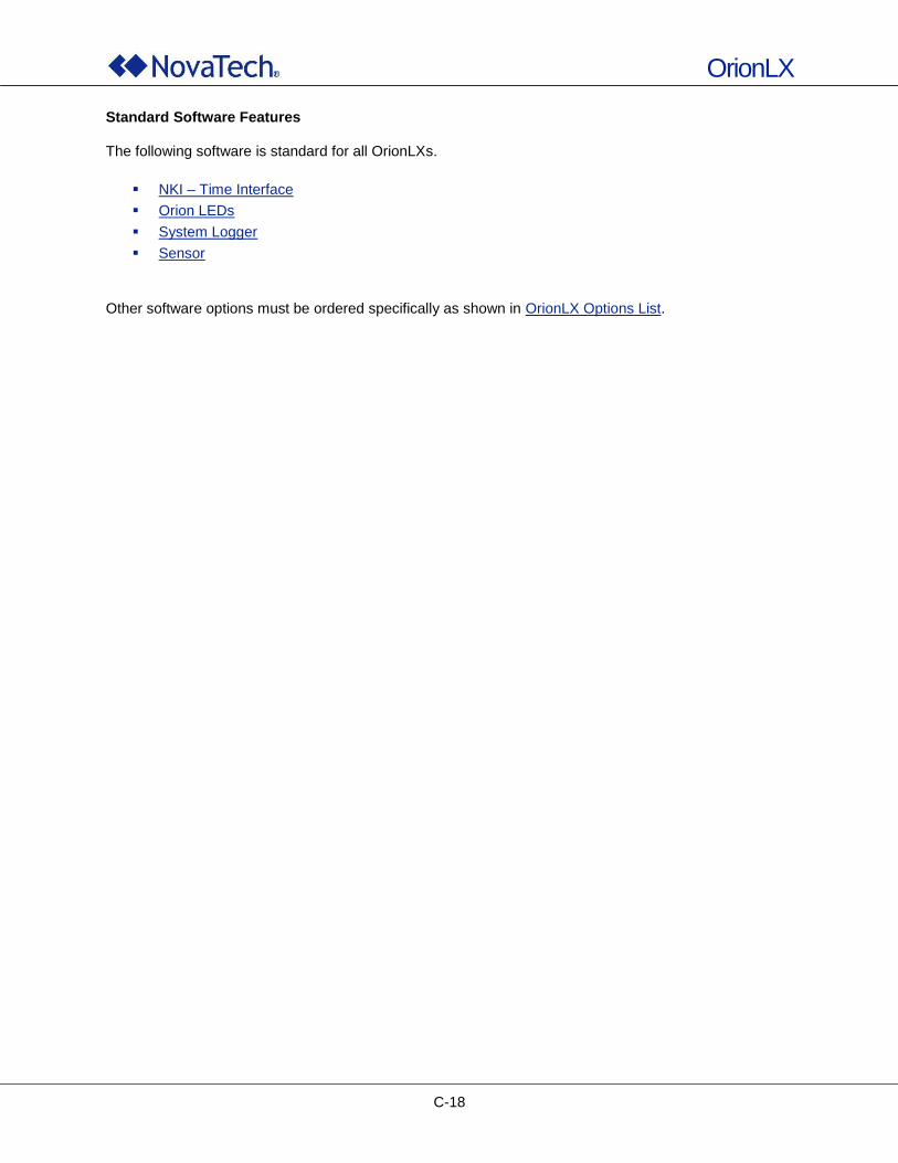
OrionLX
C-18
Standard Software Features The following software is standard for all OrionLXs.
NKI – Time Interface
Orion LEDs
System Logger
Sensor
Other software options must be ordered specifically as shown in OrionLX Options List.
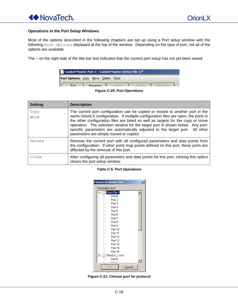
OrionLX
C-19
Operations in the Port Setup Windows Most of the options described in the following chapters are set up using a Port setup window with the
following Port Options displayed at the top of the window. Depending on the type of port, not all of the
options are available.
The * on the right side of the title bar text indicates that the current port setup has not yet been saved.
Figure C-20: Port Operations
Setting Description
Copy
Move
The current port configuration can be copied or moved to another port in the same OrionLX configuration. If multiple configuration files are open, the ports in the other configuration files are listed as well as targets for the copy or move operation. The selection window for the target port is shown below. Any port-specific parameters are automatically adjusted to the target port. All other parameters are simply moved or copied.
Delete Remove the current port with all configured parameters and data points from the configuration. If other ports map points defined on this port, these ports are affected by the removal of this port.
Close After configuring all parameters and data points for this port, clicking this option closes the port setup window.
Table C-5: Port Operations
Figure C-21: Choose port for protocol
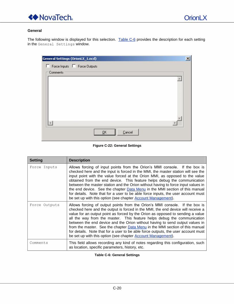
OrionLX
C-20
General
The following window is displayed for this selection. Table C-6 provides the description for each setting
in the General Settings window.
Figure C-22: General Settings
Setting Description
Force Inputs Allows forcing of input points from the Orion‟s MMI console. If the box is checked here and the input is forced in the MMI, the master station will see the input point with the value forced at the Orion MMI, as opposed to the value obtained from the end device. This feature helps debug the communication between the master station and the Orion without having to force input values in the end device. See the chapter Data Menu in the MMI section of this manual for details. Note that for a user to be able force inputs, the user account must be set up with this option (see chapter Account Management).
Force Outputs Allows forcing of output points from the Orion‟s MMI console. If the box is checked here and the output is forced in the MMI, the end device will receive a value for an output point as forced by the Orion as opposed to sending a value all the way from the master. This feature helps debug the communication between the end device and the Orion without having to send output values in from the master. See the chapter Data Menu in the MMI section of this manual for details. Note that for a user to be able force outputs, the user account must be set up with this option (see chapter Account Management).
Comments This field allows recording any kind of notes regarding this configuration, such as location, specific parameters, history, etc.
Table C-6: General Settings
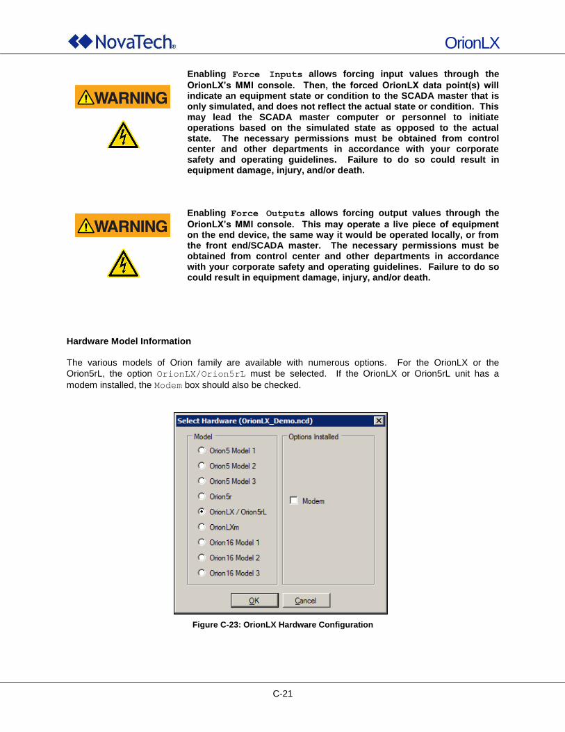
OrionLX
C-21
Enabling Force Inputs allows forcing input values through the
OrionLX’s MMI console. Then, the forced OrionLX data point(s) will indicate an equipment state or condition to the SCADA master that is only simulated, and does not reflect the actual state or condition. This may lead the SCADA master computer or personnel to initiate operations based on the simulated state as opposed to the actual state. The necessary permissions must be obtained from control center and other departments in accordance with your corporate safety and operating guidelines. Failure to do so could result in equipment damage, injury, and/or death.
Enabling Force Outputs allows forcing output values through the
OrionLX’s MMI console. This may operate a live piece of equipment on the end device, the same way it would be operated locally, or from the front end/SCADA master. The necessary permissions must be obtained from control center and other departments in accordance with your corporate safety and operating guidelines. Failure to do so could result in equipment damage, injury, and/or death.
Hardware Model Information The various models of Orion family are available with numerous options. For the OrionLX or the
Orion5rL, the option OrionLX/Orion5rL must be selected. If the OrionLX or Orion5rL unit has a
modem installed, the Modem box should also be checked.
Figure C-23: OrionLX Hardware Configuration
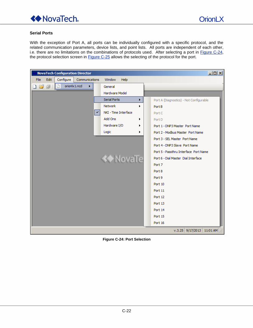
OrionLX
C-22
Serial Ports With the exception of Port A, all ports can be individually configured with a specific protocol, and the related communication parameters, device lists, and point lists. All ports are independent of each other, i.e. there are no limitations on the combinations of protocols used. After selecting a port in Figure C-24, the protocol selection screen in Figure C-25 allows the selecting of the protocol for the port.
Figure C-24: Port Selection
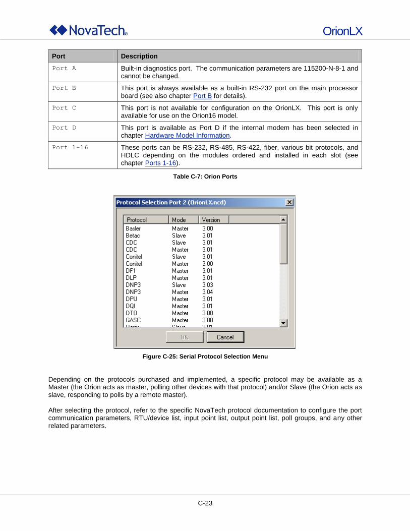
OrionLX
C-23
Port Description
Port A Built-in diagnostics port. The communication parameters are 115200-N-8-1 and cannot be changed.
Port B This port is always available as a built-in RS-232 port on the main processor board (see also chapter Port B for details).
Port C This port is not available for configuration on the OrionLX. This port is only available for use on the Orion16 model.
Port D This port is available as Port D if the internal modem has been selected in chapter Hardware Model Information.
Port 1-16 These ports can be RS-232, RS-485, RS-422, fiber, various bit protocols, and HDLC depending on the modules ordered and installed in each slot (see chapter Ports 1-16).
Table C-7: Orion Ports
Figure C-25: Serial Protocol Selection Menu
Depending on the protocols purchased and implemented, a specific protocol may be available as a Master (the Orion acts as master, polling other devices with that protocol) and/or Slave (the Orion acts as slave, responding to polls by a remote master). After selecting the protocol, refer to the specific NovaTech protocol documentation to configure the port communication parameters, RTU/device list, input point list, output point list, poll groups, and any other related parameters.
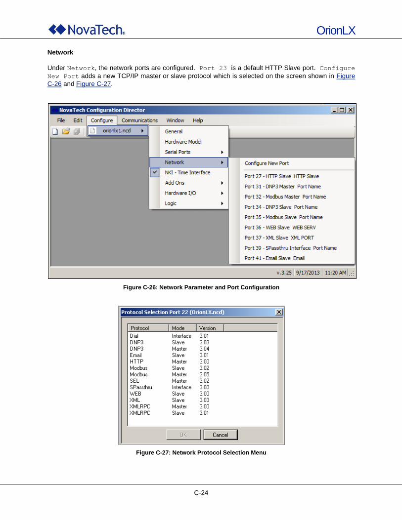
OrionLX
C-24
Network
Under Network, the network ports are configured. Port 23 is a default HTTP Slave port. Configure
New Port adds a new TCP/IP master or slave protocol which is selected on the screen shown in Figure
C-26 and Figure C-27.
Figure C-26: Network Parameter and Port Configuration
Figure C-27: Network Protocol Selection Menu

OrionLX
C-25
Depending on the network protocols purchased and installed, a specific protocol may be available as a Master (the OrionLX acts as master, polling other devices with that protocol) and/or Slave (the OrionLX acts as slave, responding to polls by a remote master). After selecting the protocol, refer to the specific NovaTech protocol documentation to configure the port communication parameters, RTU/device list, input point list, output point list, poll groups, and any other related parameters.
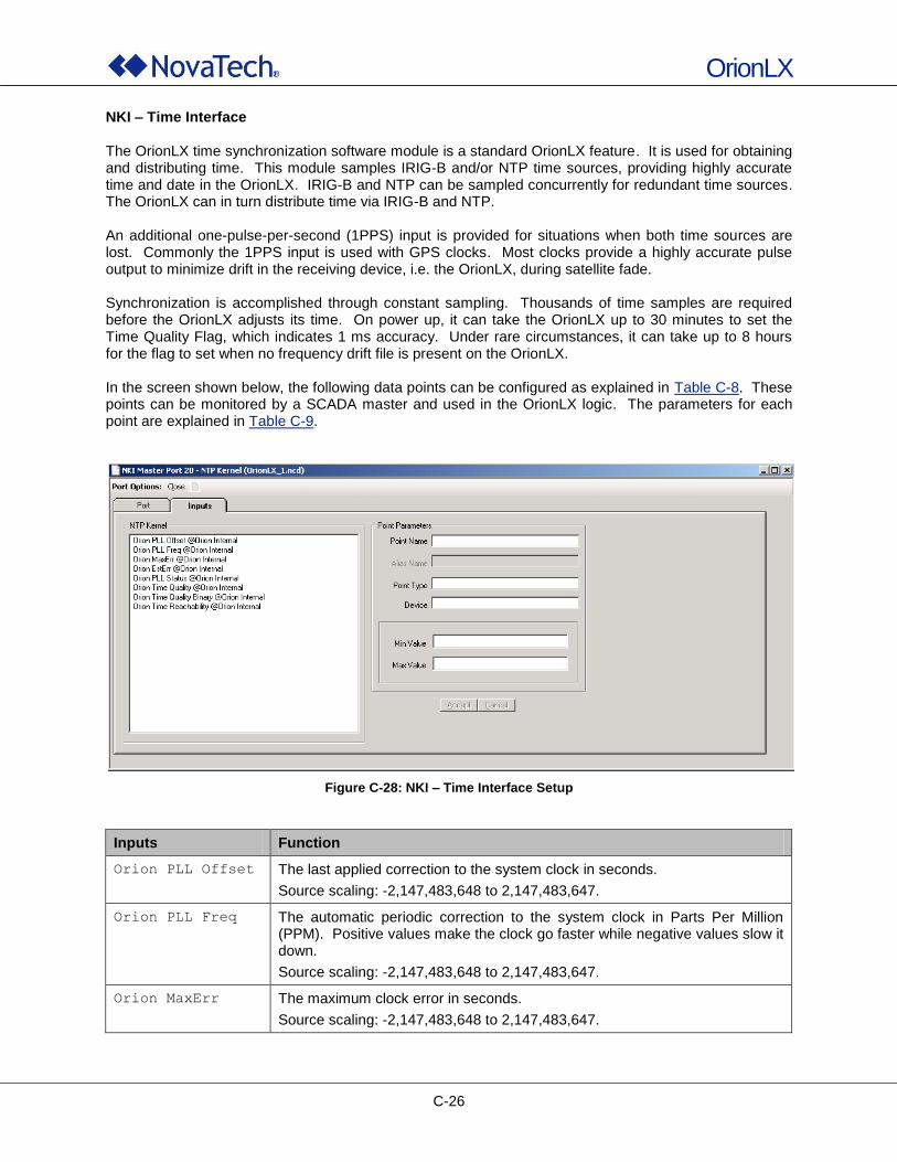
OrionLX
C-26
NKI – Time Interface The OrionLX time synchronization software module is a standard OrionLX feature. It is used for obtaining and distributing time. This module samples IRIG-B and/or NTP time sources, providing highly accurate time and date in the OrionLX. IRIG-B and NTP can be sampled concurrently for redundant time sources. The OrionLX can in turn distribute time via IRIG-B and NTP. An additional one-pulse-per-second (1PPS) input is provided for situations when both time sources are lost. Commonly the 1PPS input is used with GPS clocks. Most clocks provide a highly accurate pulse output to minimize drift in the receiving device, i.e. the OrionLX, during satellite fade. Synchronization is accomplished through constant sampling. Thousands of time samples are required before the OrionLX adjusts its time. On power up, it can take the OrionLX up to 30 minutes to set the Time Quality Flag, which indicates 1 ms accuracy. Under rare circumstances, it can take up to 8 hours for the flag to set when no frequency drift file is present on the OrionLX. In the screen shown below, the following data points can be configured as explained in Table C-8. These points can be monitored by a SCADA master and used in the OrionLX logic. The parameters for each point are explained in Table C-9.
Figure C-28: NKI – Time Interface Setup
Inputs Function
Orion PLL Offset The last applied correction to the system clock in seconds.
Source scaling: -2,147,483,648 to 2,147,483,647.
Orion PLL Freq The automatic periodic correction to the system clock in Parts Per Million (PPM). Positive values make the clock go faster while negative values slow it down.
Source scaling: -2,147,483,648 to 2,147,483,647.
Orion MaxErr The maximum clock error in seconds.
Source scaling: -2,147,483,648 to 2,147,483,647.
OrionLX
C-27
Inputs Function
Orion EstErr The estimated collective time source error in seconds. This value will vary from OrionLX to OrionLX.
Source scaling: -2,147,483,648 to 2,147,483,647.
Orion PLL Status The PLL Status is represented by a numerical range. If the PLL is enabled, synchronization is occurring (synchronization is a never-ending process when connected to a time source). Entering the following command displays the current status condition along with a brief description:
# ntpdc –c kern
Source scaling: -2,147,483,648 to 2,147,483,647.
Orion Time
Quality
The time quality of the OrionLX time daemon. This value is 0 when no time sources are reachable or if estimated error is greater than or equal to 0.03 seconds…32 if estimated error is less than 0.0005 seconds…31 if estimated error is less than 0.00075 seconds.
Source scaling: 0 to 32.
Orion Time
Quality Binary
Binary point indicating time accuracy. On indicates accuracy to +/- 500 µsec.
Source scaling: 0 to 1.
Orion Time
Reachability
This is an 8-bit register with the bits corresponding to the reachability of a configured source during the last 8 poll cycles. 0 indicates no sources were reached during the last 8 polls. 255 (decimal) indicates a source was reached during all of the last 8 polls. Bit 0 (LSB) corresponds to the most recent poll issued while bit 7 (MSB) represents the poll “8 polls ago”.
Source scaling: 0 to 255.
Table C-8: NKI – Time Interface Data Points
Parameter Description
Point Name The Point Name and the Device name are combined into the Tagname
which references the point within this port, as well as all other ports/protocols where that point might be used. Using self-explanatory names facilitates online monitoring of the OrionLX‟s operation. The maximum length is 50 characters. All printable characters are allowed except:
@ At Sign
, Comma
( Open Parenthesis
) Close Parenthesis
" Double Quote
Alias Name Displays the Alias Name (specified in the Alias module under Add Ons).
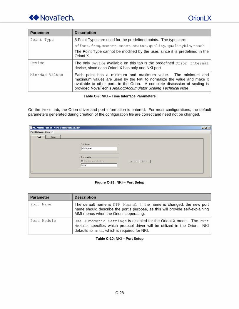
OrionLX
C-28
Parameter Description
Point Type 8 Point Types are used for the predefined points. The types are:
offset, freq, maxerr, ester, status, quality, qualitybin, reach
The Point Type cannot be modified by the user, since it is predefined in the OrionLX.
Device The only Device available on this tab is the predefined Orion Internal
device, since each OrionLX has only one NKI port.
Min/Max Values Each point has a minimum and maximum value. The minimum and maximum values are used by the NKI to normalize the value and make it available to other ports in the Orion. A complete discussion of scaling is provided NovaTech‟s Analog/Accumulator Scaling Technical Note.
Table C-9: NKI – Time Interface Parameters
On the Port tab, the Orion driver and port information is entered. For most configurations, the default
parameters generated during creation of the configuration file are correct and need not be changed.
Figure C-29: NKI – Port Setup
Parameter Description
Port Name The default name is NTP Kernel If the name is changed, the new port
name should describe the port‟s purpose, as this will provide self-explaining MMI menus when the Orion is operating.
Port Module Use Automatic Settings is disabled for the OrionLX model. The Port
Module specifies which protocol driver will be utilized in the Orion. NKI
defaults to mnki, which is required for NKI.
Table C-10: NKI – Port Setup
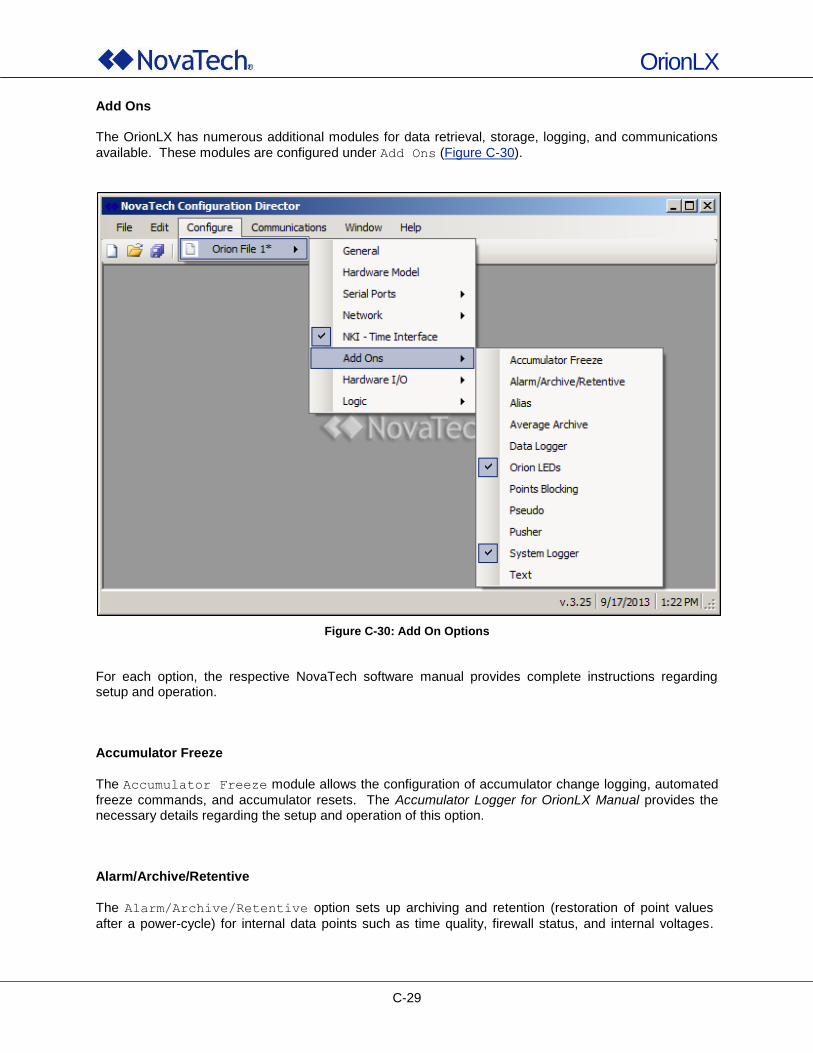
OrionLX
C-29
Add Ons The OrionLX has numerous additional modules for data retrieval, storage, logging, and communications
available. These modules are configured under Add Ons (Figure C-30).
Figure C-30: Add On Options
For each option, the respective NovaTech software manual provides complete instructions regarding setup and operation. Accumulator Freeze
The Accumulator Freeze module allows the configuration of accumulator change logging, automated
freeze commands, and accumulator resets. The Accumulator Logger for OrionLX Manual provides the necessary details regarding the setup and operation of this option. Alarm/Archive/Retentive
The Alarm/Archive/Retentive option sets up archiving and retention (restoration of point values
after a power-cycle) for internal data points such as time quality, firewall status, and internal voltages.
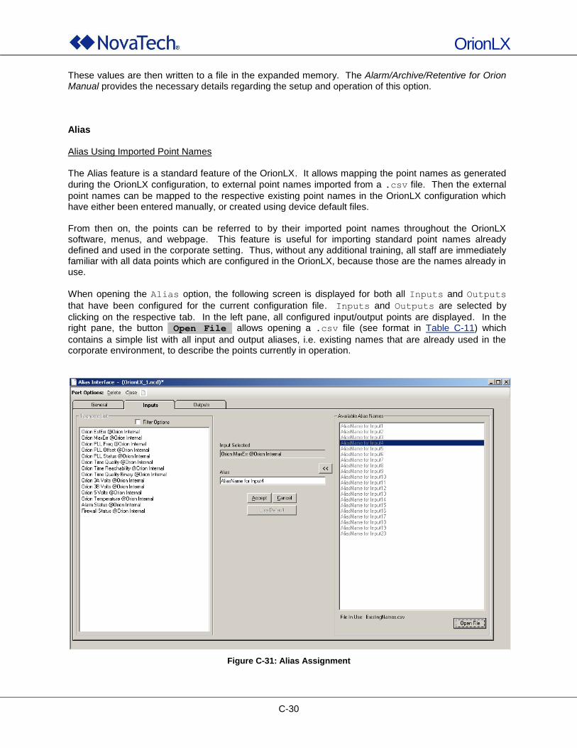
OrionLX
C-30
These values are then written to a file in the expanded memory. The Alarm/Archive/Retentive for Orion Manual provides the necessary details regarding the setup and operation of this option. Alias Alias Using Imported Point Names The Alias feature is a standard feature of the OrionLX. It allows mapping the point names as generated
during the OrionLX configuration, to external point names imported from a .csv file. Then the external
point names can be mapped to the respective existing point names in the OrionLX configuration which have either been entered manually, or created using device default files. From then on, the points can be referred to by their imported point names throughout the OrionLX software, menus, and webpage. This feature is useful for importing standard point names already defined and used in the corporate setting. Thus, without any additional training, all staff are immediately familiar with all data points which are configured in the OrionLX, because those are the names already in use.
When opening the Alias option, the following screen is displayed for both all Inputs and Outputs
that have been configured for the current configuration file. Inputs and Outputs are selected by
clicking on the respective tab. In the left pane, all configured input/output points are displayed. In the right pane, the button Open File allows opening a .csv file (see format in Table C-11) which
contains a simple list with all input and output aliases, i.e. existing names that are already used in the corporate environment, to describe the points currently in operation.
Figure C-31: Alias Assignment
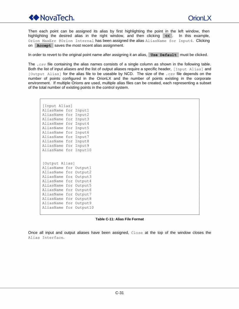
OrionLX
C-31
Then each point can be assigned its alias by first highlighting the point in the left window, then highlighting the desired alias in the right window, and then clicking << . In this example,
Orion MaxErr @Orion Internal has been assigned the alias AliasName for Input4. Clicking
on Accept saves the most recent alias assignment.
In order to revert to the original point name after assigning it an alias, Use Default must be clicked.
The .csv file containing the alias names consists of a single column as shown in the following table.
Both the list of input aliases and the list of output aliases require a specific header, [Input Alias] and
[Output Alias] for the alias file to be useable by NCD. The size of the .csv file depends on the
number of points configured in the OrionLX and the number of points existing in the corporate environment. If multiple Orions are used, multiple alias files can be created, each representing a subset of the total number of existing points in the control system.
[Input Alias]
AliasName for Input1
AliasName for Input2
AliasName for Input3
AliasName for Input4
AliasName for Input5
AliasName for Input6
AliasName for Input7
AliasName for Input8
AliasName for Input9
AliasName for Input10
[Output Alias]
AliasName for Output1
AliasName for Output2
AliasName for Output3
AliasName for Output4
AliasName for Output5
AliasName for Output6
AliasName for Output7
AliasName for Output8
AliasName for Output9
AliasName for Output10
Table C-11: Alias File Format
Once all input and output aliases have been assigned, Close at the top of the window closes the
Alias Interface.
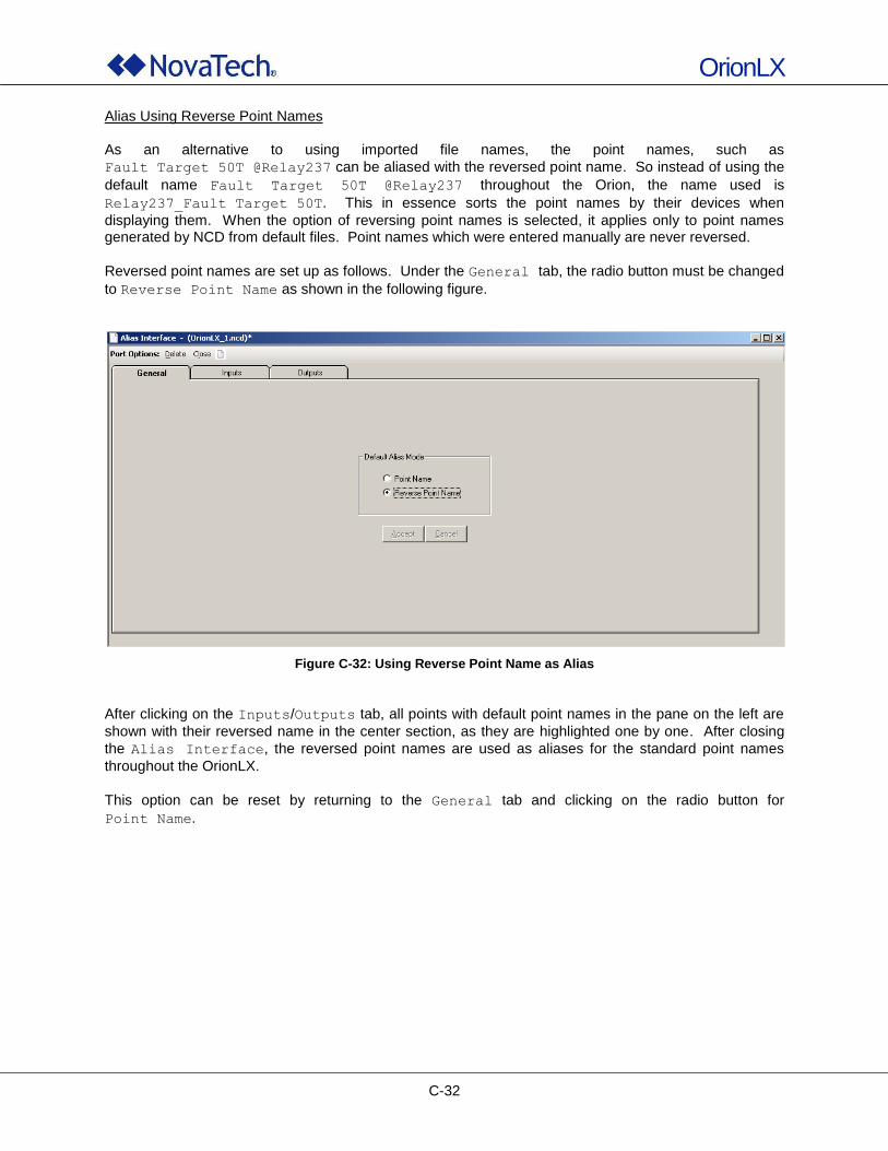
OrionLX
C-32
Alias Using Reverse Point Names As an alternative to using imported file names, the point names, such as
Fault Target 50T @Relay237 can be aliased with the reversed point name. So instead of using the
default name Fault Target 50T @Relay237 throughout the Orion, the name used is
Relay237_Fault Target 50T. This in essence sorts the point names by their devices when
displaying them. When the option of reversing point names is selected, it applies only to point names generated by NCD from default files. Point names which were entered manually are never reversed.
Reversed point names are set up as follows. Under the General tab, the radio button must be changed
to Reverse Point Name as shown in the following figure.
Figure C-32: Using Reverse Point Name as Alias
After clicking on the Inputs/Outputs tab, all points with default point names in the pane on the left are
shown with their reversed name in the center section, as they are highlighted one by one. After closing
the Alias Interface, the reversed point names are used as aliases for the standard point names
throughout the OrionLX.
This option can be reset by returning to the General tab and clicking on the radio button for
Point Name.
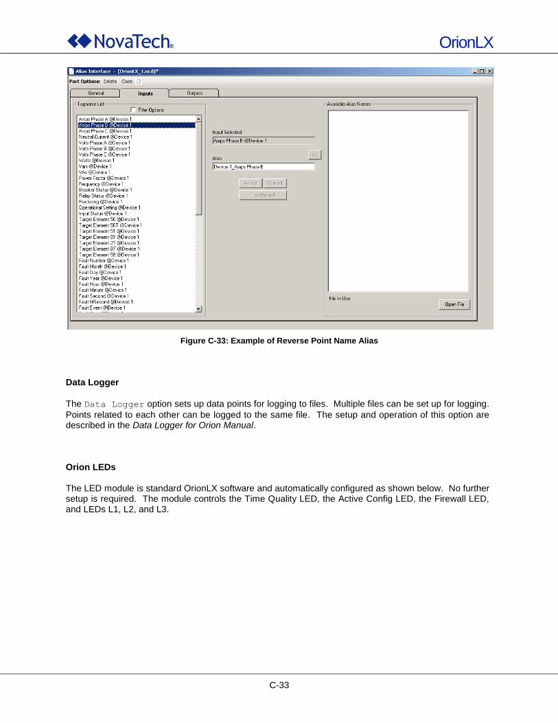
OrionLX
C-33
Figure C-33: Example of Reverse Point Name Alias
Data Logger
The Data Logger option sets up data points for logging to files. Multiple files can be set up for logging.
Points related to each other can be logged to the same file. The setup and operation of this option are described in the Data Logger for Orion Manual. Orion LEDs The LED module is standard OrionLX software and automatically configured as shown below. No further setup is required. The module controls the Time Quality LED, the Active Config LED, the Firewall LED, and LEDs L1, L2, and L3.
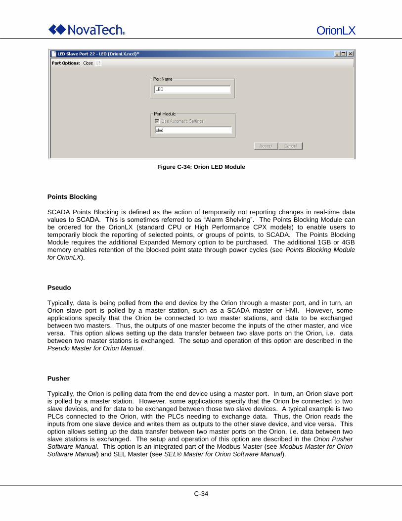
OrionLX
C-34
Figure C-34: Orion LED Module
Points Blocking SCADA Points Blocking is defined as the action of temporarily not reporting changes in real-time data values to SCADA. This is sometimes referred to as “Alarm Shelving”. The Points Blocking Module can be ordered for the OrionLX (standard CPU or High Performance CPX models) to enable users to temporarily block the reporting of selected points, or groups of points, to SCADA. The Points Blocking Module requires the additional Expanded Memory option to be purchased. The additional 1GB or 4GB memory enables retention of the blocked point state through power cycles (see Points Blocking Module for OrionLX). Pseudo Typically, data is being polled from the end device by the Orion through a master port, and in turn, an Orion slave port is polled by a master station, such as a SCADA master or HMI. However, some applications specify that the Orion be connected to two master stations, and data to be exchanged between two masters. Thus, the outputs of one master become the inputs of the other master, and vice versa. This option allows setting up the data transfer between two slave ports on the Orion, i.e. data between two master stations is exchanged. The setup and operation of this option are described in the Pseudo Master for Orion Manual. Pusher Typically, the Orion is polling data from the end device using a master port. In turn, an Orion slave port is polled by a master station. However, some applications specify that the Orion be connected to two slave devices, and for data to be exchanged between those two slave devices. A typical example is two PLCs connected to the Orion, with the PLCs needing to exchange data. Thus, the Orion reads the inputs from one slave device and writes them as outputs to the other slave device, and vice versa. This option allows setting up the data transfer between two master ports on the Orion, i.e. data between two slave stations is exchanged. The setup and operation of this option are described in the Orion Pusher Software Manual. This option is an integrated part of the Modbus Master (see Modbus Master for Orion Software Manual) and SEL Master (see SEL® Master for Orion Software Manual).
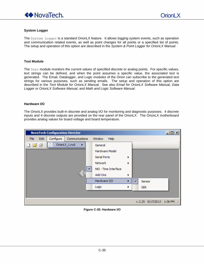
OrionLX
C-35
System Logger
The System Logger is a standard OrionLX feature. It allows logging system events, such as operation
and communication related events, as well as point changes for all points or a specified list of points. The setup and operation of this option are described in the System & Point Logger for OrionLX Manual. Text Module
The Text module monitors the current values of specified discrete or analog points. For specific values,
text strings can be defined, and when the point assumes a specific value, the associated text is generated. The Email, Datalogger, and Logic modules of the Orion can subscribe to the generated text strings for various purposes, such as sending emails. The setup and operation of this option are described in the Text Module for OrionLX Manual. See also Email for OrionLX Software Manual, Data Logger or OrionLX Software Manual, and Math and Logic Software Manual. Hardware I/O The OrionLX provides built-in discrete and analog I/O for monitoring and diagnostic purposes. 4 discrete inputs and 4 discrete outputs are provided on the rear panel of the OrionLX. The OrionLX motherboard provides analog values for board voltage and board temperature.
Figure C-35: Hardware I/O
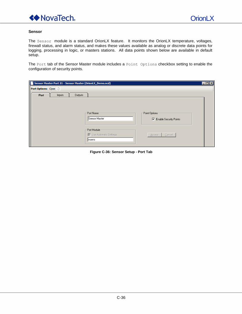
OrionLX
C-36
Sensor
The Sensor module is a standard OrionLX feature. It monitors the OrionLX temperature, voltages,
firewall status, and alarm status, and makes these values available as analog or discrete data points for logging, processing in logic, or masters stations. All data points shown below are available in default setup.
The Port tab of the Sensor Master module includes a Point Options checkbox setting to enable the
configuration of security points.
Figure C-36: Sensor Setup - Port Tab
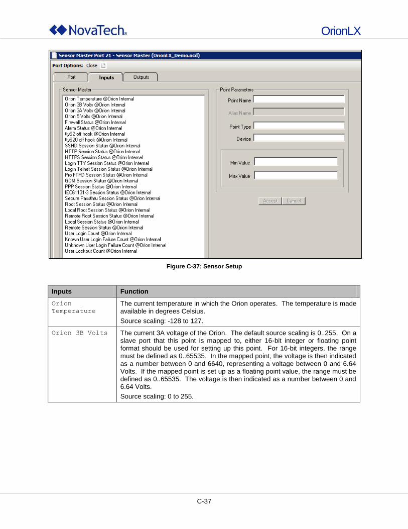
OrionLX
C-37
Figure C-37: Sensor Setup
Inputs Function
Orion
Temperature
The current temperature in which the Orion operates. The temperature is made available in degrees Celsius.
Source scaling: -128 to 127.
Orion 3B Volts The current 3A voltage of the Orion. The default source scaling is 0..255. On a slave port that this point is mapped to, either 16-bit integer or floating point format should be used for setting up this point. For 16-bit integers, the range must be defined as 0..65535. In the mapped point, the voltage is then indicated as a number between 0 and 6640, representing a voltage between 0 and 6.64 Volts. If the mapped point is set up as a floating point value, the range must be defined as 0..65535. The voltage is then indicated as a number between 0 and 6.64 Volts.
Source scaling: 0 to 255.
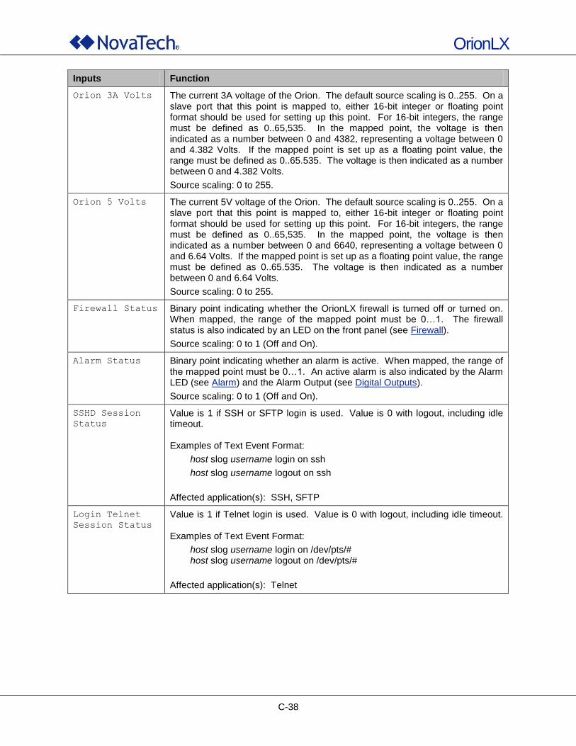
OrionLX
C-38
Inputs Function
Orion 3A Volts The current 3A voltage of the Orion. The default source scaling is 0..255. On a slave port that this point is mapped to, either 16-bit integer or floating point format should be used for setting up this point. For 16-bit integers, the range must be defined as 0..65,535. In the mapped point, the voltage is then indicated as a number between 0 and 4382, representing a voltage between 0 and 4.382 Volts. If the mapped point is set up as a floating point value, the range must be defined as 0..65.535. The voltage is then indicated as a number between 0 and 4.382 Volts.
Source scaling: 0 to 255.
Orion 5 Volts The current 5V voltage of the Orion. The default source scaling is 0..255. On a slave port that this point is mapped to, either 16-bit integer or floating point format should be used for setting up this point. For 16-bit integers, the range must be defined as 0..65,535. In the mapped point, the voltage is then indicated as a number between 0 and 6640, representing a voltage between 0 and 6.64 Volts. If the mapped point is set up as a floating point value, the range must be defined as 0..65.535. The voltage is then indicated as a number between 0 and 6.64 Volts.
Source scaling: 0 to 255.
Firewall Status Binary point indicating whether the OrionLX firewall is turned off or turned on. When mapped, the range of the mapped point must be 0…1. The firewall status is also indicated by an LED on the front panel (see Firewall).
Source scaling: 0 to 1 (Off and On).
Alarm Status Binary point indicating whether an alarm is active. When mapped, the range of the mapped point must be 0…1. An active alarm is also indicated by the Alarm LED (see Alarm) and the Alarm Output (see Digital Outputs).
Source scaling: 0 to 1 (Off and On).
SSHD Session
Status
Value is 1 if SSH or SFTP login is used. Value is 0 with logout, including idle timeout. Examples of Text Event Format:
host slog username login on ssh
host slog username logout on ssh
Affected application(s): SSH, SFTP
Login Telnet
Session Status
Value is 1 if Telnet login is used. Value is 0 with logout, including idle timeout. Examples of Text Event Format:
host slog username login on /dev/pts/# host slog username logout on /dev/pts/#
Affected application(s): Telnet
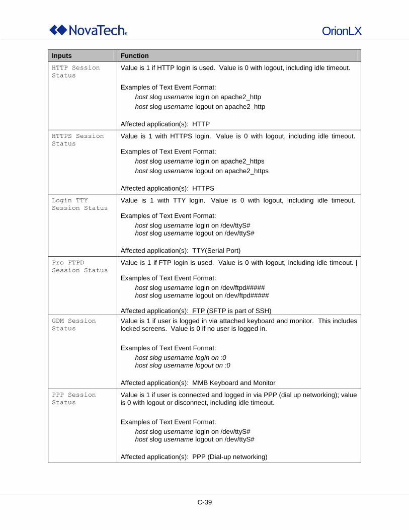
OrionLX
C-39
Inputs Function
HTTP Session
Status
Value is 1 if HTTP login is used. Value is 0 with logout, including idle timeout.
Examples of Text Event Format:
host slog username login on apache2_http
host slog username logout on apache2_http
Affected application(s): HTTP
HTTPS Session
Status
Value is 1 with HTTPS login. Value is 0 with logout, including idle timeout. Examples of Text Event Format:
host slog username login on apache2_https
host slog username logout on apache2_https
Affected application(s): HTTPS
Login TTY
Session Status
Value is 1 with TTY login. Value is 0 with logout, including idle timeout. Examples of Text Event Format:
host slog username login on /dev/ttyS# host slog username logout on /dev/ttyS#
Affected application(s): TTY(Serial Port)
Pro FTPD
Session Status
Value is 1 if FTP login is used. Value is 0 with logout, including idle timeout. | Examples of Text Event Format:
host slog username login on /dev/ftpd##### host slog username logout on /dev/ftpd#####
Affected application(s): FTP (SFTP is part of SSH)
GDM Session
Status
Value is 1 if user is logged in via attached keyboard and monitor. This includes locked screens. Value is 0 if no user is logged in.
Examples of Text Event Format:
host slog username login on :0 host slog username logout on :0
Affected application(s): MMB Keyboard and Monitor
PPP Session
Status
Value is 1 if user is connected and logged in via PPP (dial up networking); value is 0 with logout or disconnect, including idle timeout.
Examples of Text Event Format:
host slog username login on /dev/ttyS# host slog username logout on /dev/ttyS#
Affected application(s): PPP (Dial-up networking)
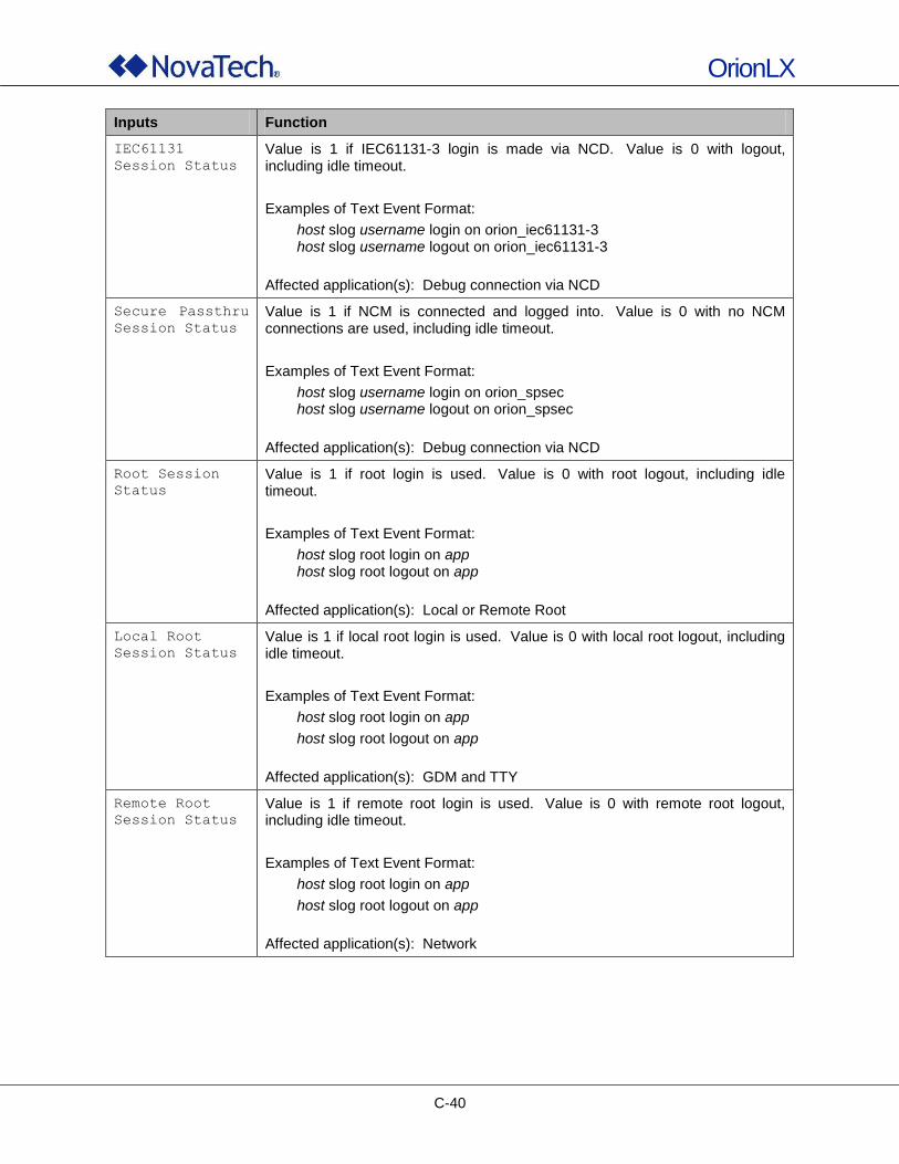
OrionLX
C-40
Inputs Function
IEC61131
Session Status
Value is 1 if IEC61131-3 login is made via NCD. Value is 0 with logout, including idle timeout.
Examples of Text Event Format:
host slog username login on orion_iec61131-3 host slog username logout on orion_iec61131-3
Affected application(s): Debug connection via NCD
Secure Passthru
Session Status
Value is 1 if NCM is connected and logged into. Value is 0 with no NCM connections are used, including idle timeout.
Examples of Text Event Format:
host slog username login on orion_spsec host slog username logout on orion_spsec
Affected application(s): Debug connection via NCD
Root Session
Status
Value is 1 if root login is used. Value is 0 with root logout, including idle timeout.
Examples of Text Event Format:
host slog root login on app host slog root logout on app
Affected application(s): Local or Remote Root
Local Root
Session Status
Value is 1 if local root login is used. Value is 0 with local root logout, including idle timeout.
Examples of Text Event Format:
host slog root login on app
host slog root logout on app
Affected application(s): GDM and TTY
Remote Root
Session Status
Value is 1 if remote root login is used. Value is 0 with remote root logout, including idle timeout.
Examples of Text Event Format:
host slog root login on app
host slog root logout on app
Affected application(s): Network
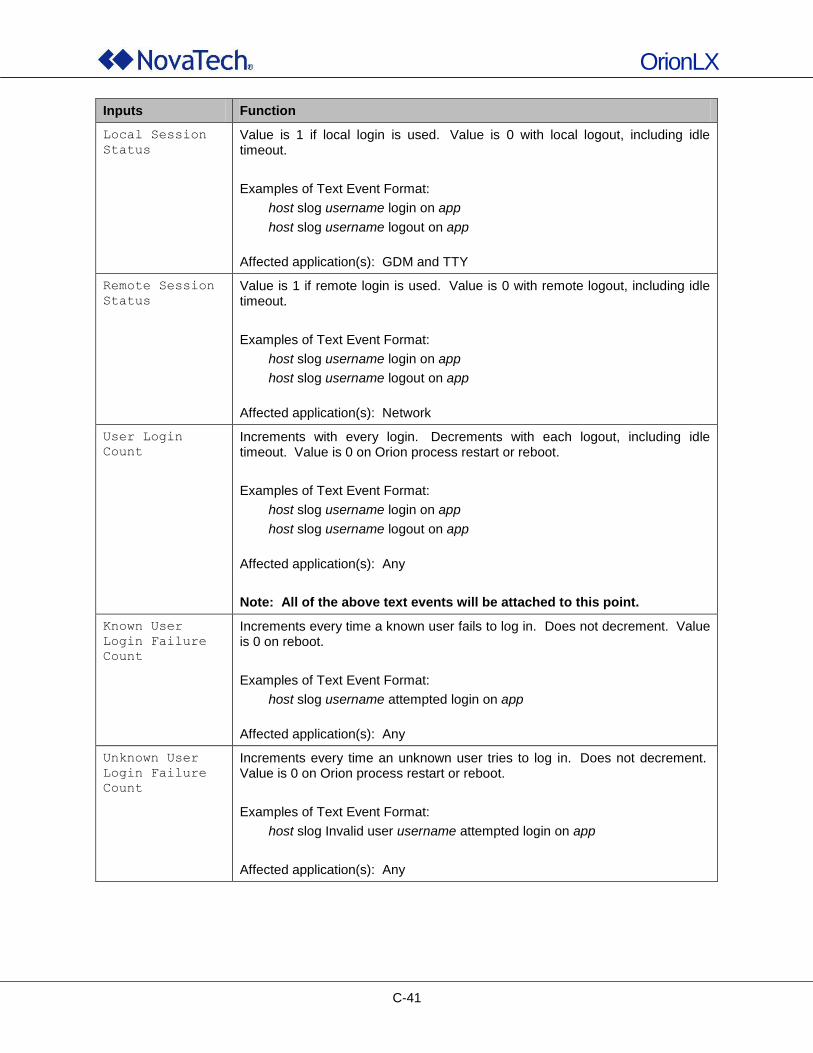
OrionLX
C-41
Inputs Function
Local Session
Status
Value is 1 if local login is used. Value is 0 with local logout, including idle timeout.
Examples of Text Event Format:
host slog username login on app
host slog username logout on app
Affected application(s): GDM and TTY
Remote Session
Status
Value is 1 if remote login is used. Value is 0 with remote logout, including idle timeout.
Examples of Text Event Format:
host slog username login on app
host slog username logout on app
Affected application(s): Network
User Login
Count
Increments with every login. Decrements with each logout, including idle timeout. Value is 0 on Orion process restart or reboot.
Examples of Text Event Format:
host slog username login on app
host slog username logout on app
Affected application(s): Any
Note: All of the above text events will be attached to this point.
Known User
Login Failure
Count
Increments every time a known user fails to log in. Does not decrement. Value is 0 on reboot.
Examples of Text Event Format:
host slog username attempted login on app
Affected application(s): Any
Unknown User
Login Failure
Count
Increments every time an unknown user tries to log in. Does not decrement. Value is 0 on Orion process restart or reboot.
Examples of Text Event Format:
host slog Invalid user username attempted login on app
Affected application(s): Any
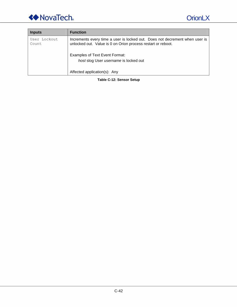
OrionLX
C-42
Inputs Function
User Lockout
Count
Increments every time a user is locked out. Does not decrement when user is unlocked out. Value is 0 on Orion process restart or reboot.
Examples of Text Event Format:
host slog User username is locked out
Affected application(s): Any
Table C-12: Sensor Setup
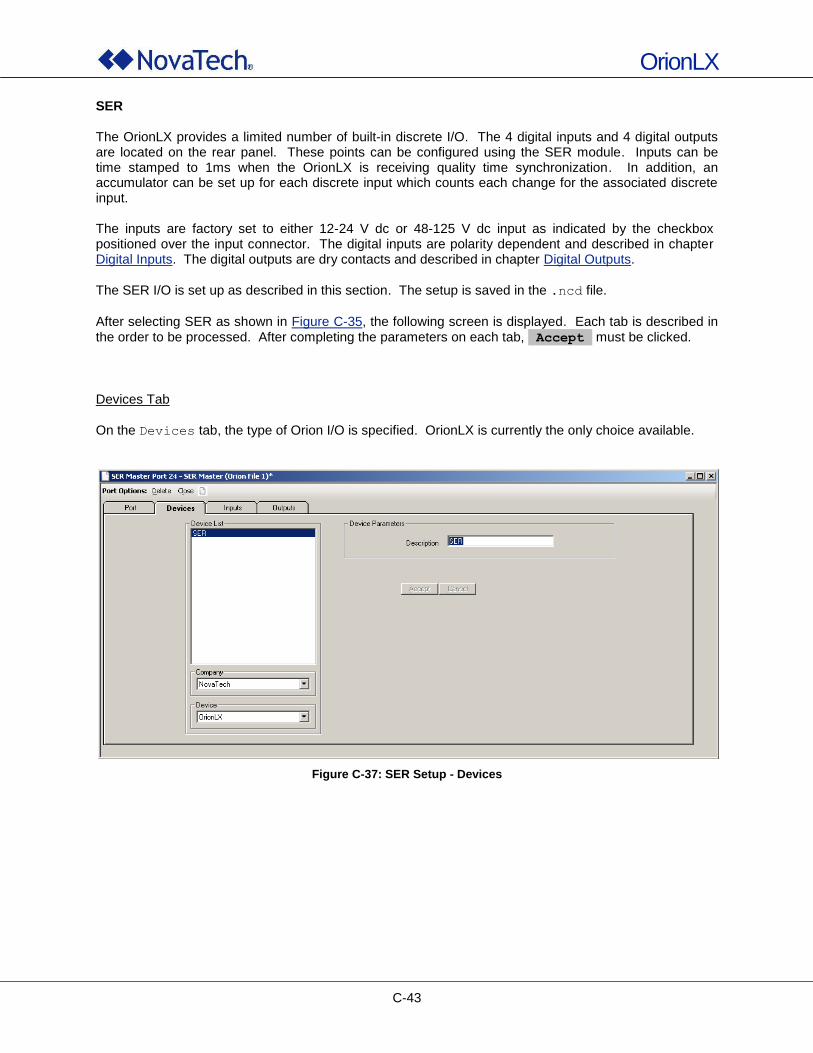
OrionLX
C-43
SER The OrionLX provides a limited number of built-in discrete I/O. The 4 digital inputs and 4 digital outputs are located on the rear panel. These points can be configured using the SER module. Inputs can be time stamped to 1ms when the OrionLX is receiving quality time synchronization. In addition, an accumulator can be set up for each discrete input which counts each change for the associated discrete input. The inputs are factory set to either 12-24 V dc or 48-125 V dc input as indicated by the checkbox positioned over the input connector. The digital inputs are polarity dependent and described in chapter Digital Inputs. The digital outputs are dry contacts and described in chapter Digital Outputs.
The SER I/O is set up as described in this section. The setup is saved in the .ncd file.
After selecting SER as shown in Figure C-35, the following screen is displayed. Each tab is described in the order to be processed. After completing the parameters on each tab, Accept must be clicked.
Devices Tab
On the Devices tab, the type of Orion I/O is specified. OrionLX is currently the only choice available.
Figure C-37: SER Setup - Devices
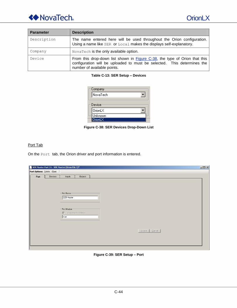
OrionLX
C-44
Parameter Description
Description The name entered here will be used throughout the Orion configuration.
Using a name like SER or Local makes the displays self-explanatory.
Company NovaTech is the only available option.
Device From this drop-down list shown in Figure C-38, the type of Orion that this configuration will be uploaded to must be selected. This determines the number of available points.
Table C-13: SER Setup – Devices
Figure C-38: SER Devices Drop-Down List
Port Tab
On the Port tab, the Orion driver and port information is entered.
Figure C-39: SER Setup – Port
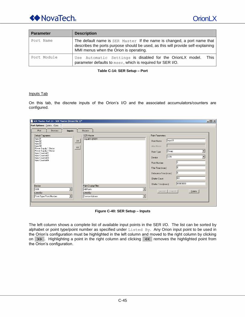
OrionLX
C-45
Parameter Description
Port Name The default name is SER Master If the name is changed, a port name that
describes the ports purpose should be used, as this will provide self-explaining MMI menus when the Orion is operating.
Port Module Use Automatic Settings is disabled for the OrionLX model. This
parameter defaults to mser, which is required for SER I/O.
Table C-14: SER Setup – Port
Inputs Tab On this tab, the discrete inputs of the Orion‟s I/O and the associated accumulators/counters are configured.
Figure C-40: SER Setup – Inputs
The left column shows a complete list of available input points in the SER I/O. The list can be sorted by
alphabet or point type/point number as specified under Listed By. Any Orion input point to be used in
the Orion‟s configuration must be highlighted in the left column and moved to the right column by clicking on >> . Highlighting a point in the right column and clicking << removes the highlighted point from
the Orion‟s configuration.
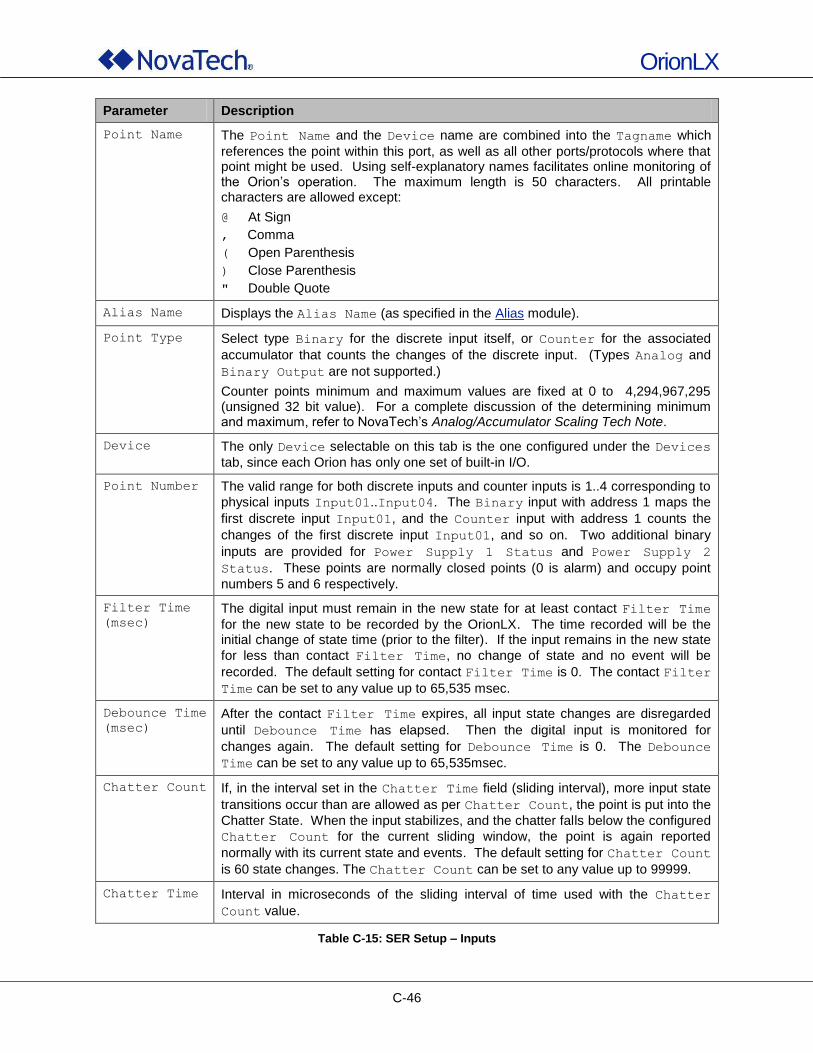
OrionLX
C-46
Parameter Description
Point Name The Point Name and the Device name are combined into the Tagname which
references the point within this port, as well as all other ports/protocols where that point might be used. Using self-explanatory names facilitates online monitoring of the Orion‟s operation. The maximum length is 50 characters. All printable characters are allowed except:
@ At Sign
, Comma
( Open Parenthesis
) Close Parenthesis
" Double Quote
Alias Name Displays the Alias Name (as specified in the Alias module).
Point Type Select type Binary for the discrete input itself, or Counter for the associated
accumulator that counts the changes of the discrete input. (Types Analog and
Binary Output are not supported.)
Counter points minimum and maximum values are fixed at 0 to 4,294,967,295 (unsigned 32 bit value). For a complete discussion of the determining minimum and maximum, refer to NovaTech‟s Analog/Accumulator Scaling Tech Note.
Device The only Device selectable on this tab is the one configured under the Devices
tab, since each Orion has only one set of built-in I/O.
Point Number The valid range for both discrete inputs and counter inputs is 1..4 corresponding to
physical inputs Input01..Input04. The Binary input with address 1 maps the
first discrete input Input01, and the Counter input with address 1 counts the
changes of the first discrete input Input01, and so on. Two additional binary
inputs are provided for Power Supply 1 Status and Power Supply 2
Status. These points are normally closed points (0 is alarm) and occupy point
numbers 5 and 6 respectively.
Filter Time
(msec)
The digital input must remain in the new state for at least contact Filter Time
for the new state to be recorded by the OrionLX. The time recorded will be the initial change of state time (prior to the filter). If the input remains in the new state
for less than contact Filter Time, no change of state and no event will be
recorded. The default setting for contact Filter Time is 0. The contact Filter
Time can be set to any value up to 65,535 msec.
Debounce Time
(msec)
After the contact Filter Time expires, all input state changes are disregarded
until Debounce Time has elapsed. Then the digital input is monitored for
changes again. The default setting for Debounce Time is 0. The Debounce
Time can be set to any value up to 65,535msec.
Chatter Count If, in the interval set in the Chatter Time field (sliding interval), more input state
transitions occur than are allowed as per Chatter Count, the point is put into the
Chatter State. When the input stabilizes, and the chatter falls below the configured
Chatter Count for the current sliding window, the point is again reported
normally with its current state and events. The default setting for Chatter Count
is 60 state changes. The Chatter Count can be set to any value up to 99999.
Chatter Time Interval in microseconds of the sliding interval of time used with the Chatter
Count value.
Table C-15: SER Setup – Inputs
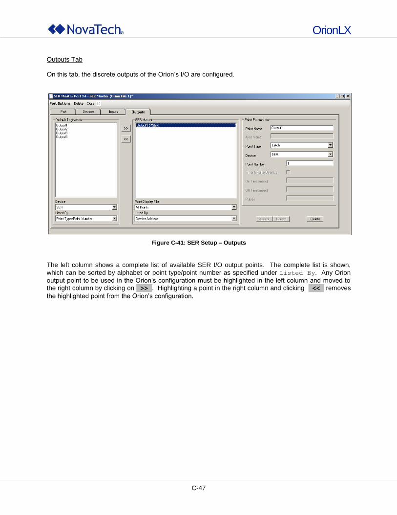
OrionLX
C-47
Outputs Tab On this tab, the discrete outputs of the Orion‟s I/O are configured.
Figure C-41: SER Setup – Outputs
The left column shows a complete list of available SER I/O output points. The complete list is shown,
which can be sorted by alphabet or point type/point number as specified under Listed By. Any Orion
output point to be used in the Orion‟s configuration must be highlighted in the left column and moved to the right column by clicking on >> . Highlighting a point in the right column and clicking << removes
the highlighted point from the Orion‟s configuration.
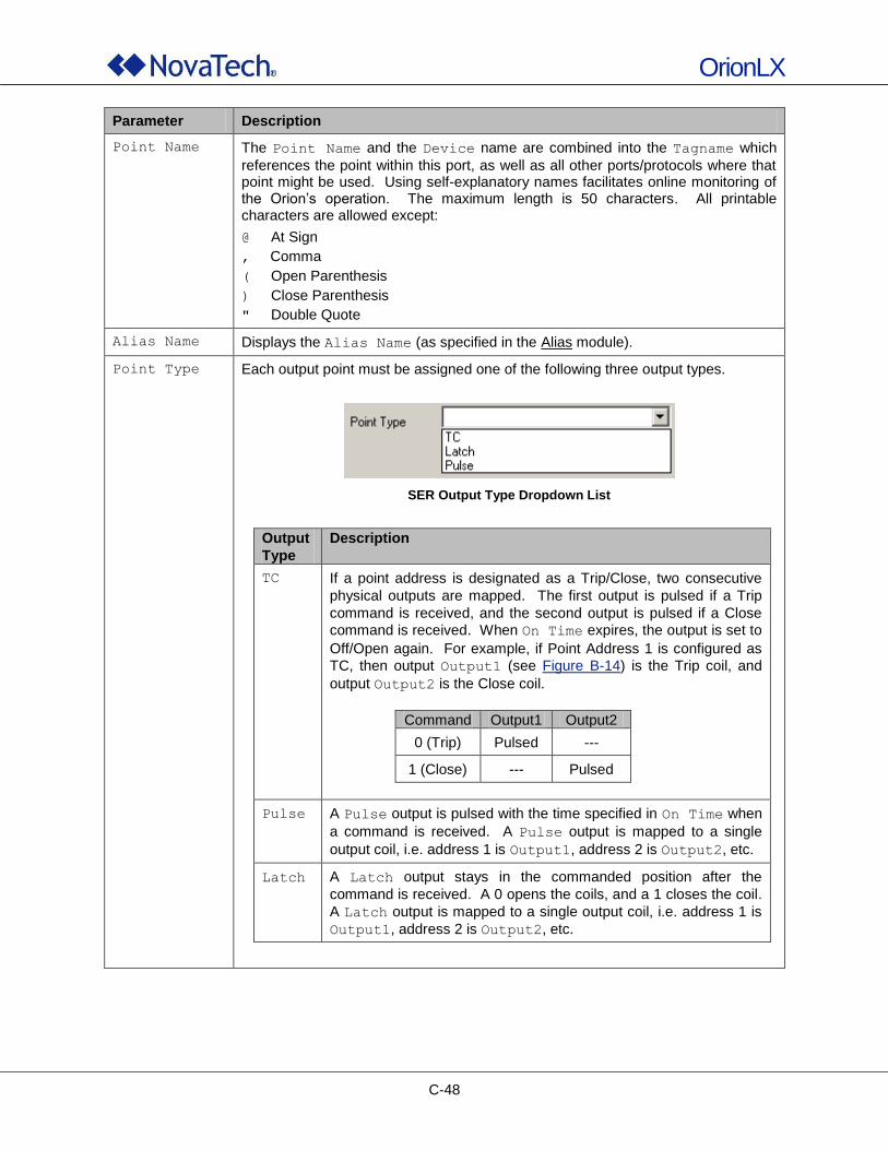
OrionLX
C-48
Parameter Description
Point Name The Point Name and the Device name are combined into the Tagname which
references the point within this port, as well as all other ports/protocols where that point might be used. Using self-explanatory names facilitates online monitoring of the Orion‟s operation. The maximum length is 50 characters. All printable characters are allowed except:
@ At Sign
, Comma
( Open Parenthesis
) Close Parenthesis
" Double Quote
Alias Name Displays the Alias Name (as specified in the Alias module).
Point Type Each output point must be assigned one of the following three output types.
SER Output Type Dropdown List
Output
Type
Description
TC If a point address is designated as a Trip/Close, two consecutive
physical outputs are mapped. The first output is pulsed if a Trip
command is received, and the second output is pulsed if a Close
command is received. When On Time expires, the output is set to
Off/Open again. For example, if Point Address 1 is configured as
TC, then output Output1 (see Figure B-14) is the Trip coil, and
output Output2 is the Close coil.
Command Output1 Output2
0 (Trip) Pulsed ---
1 (Close) --- Pulsed
Pulse A Pulse output is pulsed with the time specified in On Time when
a command is received. A Pulse output is mapped to a single
output coil, i.e. address 1 is Output1, address 2 is Output2, etc.
Latch A Latch output stays in the commanded position after the
command is received. A 0 opens the coils, and a 1 closes the coil.
A Latch output is mapped to a single output coil, i.e. address 1 is
Output1, address 2 is Output2, etc.
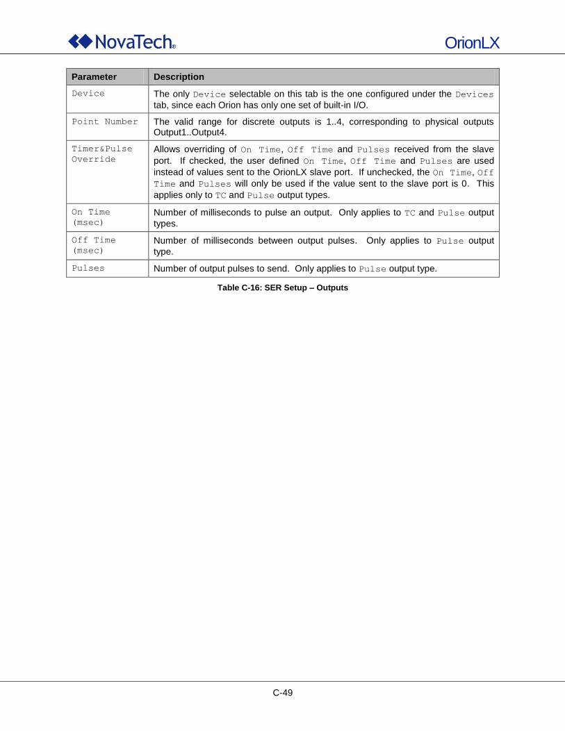
OrionLX
C-49
Parameter Description
Device The only Device selectable on this tab is the one configured under the Devices
tab, since each Orion has only one set of built-in I/O.
Point Number The valid range for discrete outputs is 1..4, corresponding to physical outputs Output1..Output4.
Timer&Pulse
Override
Allows overriding of On Time, Off Time and Pulses received from the slave
port. If checked, the user defined On Time, Off Time and Pulses are used
instead of values sent to the OrionLX slave port. If unchecked, the On Time, Off
Time and Pulses will only be used if the value sent to the slave port is 0. This
applies only to TC and Pulse output types.
On Time
(msec)
Number of milliseconds to pulse an output. Only applies to TC and Pulse output
types.
Off Time
(msec)
Number of milliseconds between output pulses. Only applies to Pulse output
type.
Pulses Number of output pulses to send. Only applies to Pulse output type.
Table C-16: SER Setup – Outputs
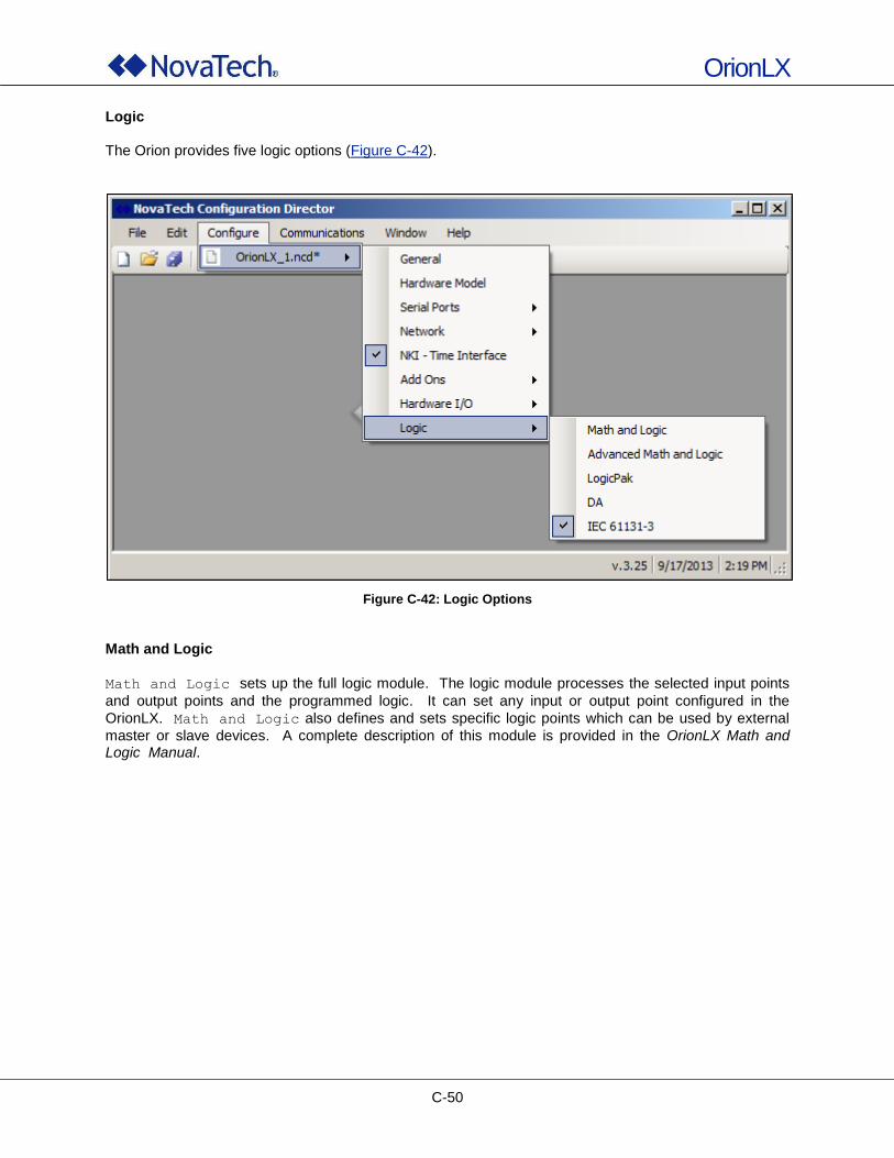
OrionLX
C-50
Logic The Orion provides five logic options (Figure C-42).
Figure C-42: Logic Options
Math and Logic
Math and Logic sets up the full logic module. The logic module processes the selected input points
and output points and the programmed logic. It can set any input or output point configured in the
OrionLX. Math and Logic also defines and sets specific logic points which can be used by external
master or slave devices. A complete description of this module is provided in the OrionLX Math and Logic Manual.
OrionLX
C-51
Advanced Math and Logic
Advanced Math and Logic utilizes the Lua programming language (Lua 5.1.4 – Copyright © 1994-
2008 Lua.org, PUC-Rio). A complete description of this module is provided in the OrionLX Math and
Logic Manual. Advanced Math and Logic supports the following programming elements:
Variable declarations
Conditional statements
Repetitive statements (loops)
Functions For a complete reference of the Lua programming language, refer to the complete online reference manual via the following link: Hhttp://www.lua.org/manual/5.1/manual.html H. LogicPak
The LogicPak module provides two pre-packaged functions:
Automatic switchover between redundant field devices
OR‟ing of status bits, such as Comm Fail flags, to combine values from multiple field devices into single bit for the master
A complete description of this module is provided in the LogicPak for Orion Manual. Distribution Automation (DA)
DA sets up the Distribution Automation module which provides control for electrical grid functions and
operations on the distribution level. Before the DA Logic can be set up, all master ports in the OrionLX that communicate with the respective RTUs in the DA Logic must be set up. A complete description of this module is provided in the DA Logic for Orion Manual. IEC 61131-3 The full set of IEC 61131 programming languages is available for the OrionLX:
Structured Flow Chart
Function Block Diagram
Ladder Diagram
Structured Text
Instruction Language A complete description of this module is provided in the IEC 61131 for OrionLX Software Manual.
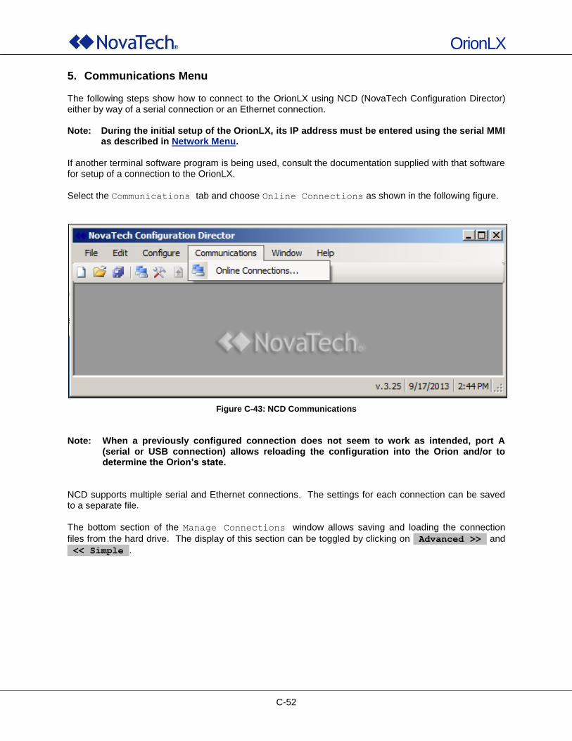
OrionLX
C-52
5. Communications Menu The following steps show how to connect to the OrionLX using NCD (NovaTech Configuration Director) either by way of a serial connection or an Ethernet connection. Note: During the initial setup of the OrionLX, its IP address must be entered using the serial MMI
as described in Network Menu. If another terminal software program is being used, consult the documentation supplied with that software for setup of a connection to the OrionLX.
Select the Communications tab and choose Online Connections as shown in the following figure.
Figure C-43: NCD Communications
Note: When a previously configured connection does not seem to work as intended, port A
(serial or USB connection) allows reloading the configuration into the Orion and/or to determine the Orion’s state.
NCD supports multiple serial and Ethernet connections. The settings for each connection can be saved to a separate file.
The bottom section of the Manage Connections window allows saving and loading the connection
files from the hard drive. The display of this section can be toggled by clicking on Advanced >> and
<< Simple .
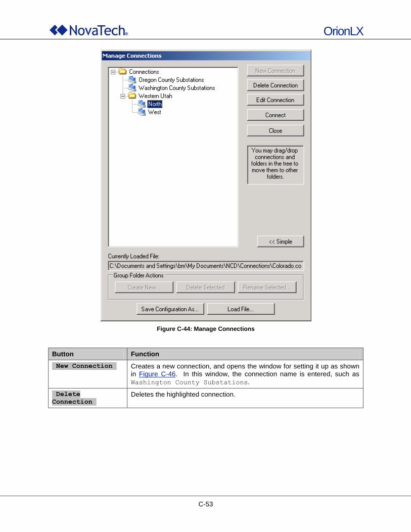
OrionLX
C-53
Figure C-44: Manage Connections
Button Function
New Connection Creates a new connection, and opens the window for setting it up as shown in Figure C-46. In this window, the connection name is entered, such as
Washington County Substations.
Delete
Connection Deletes the highlighted connection.
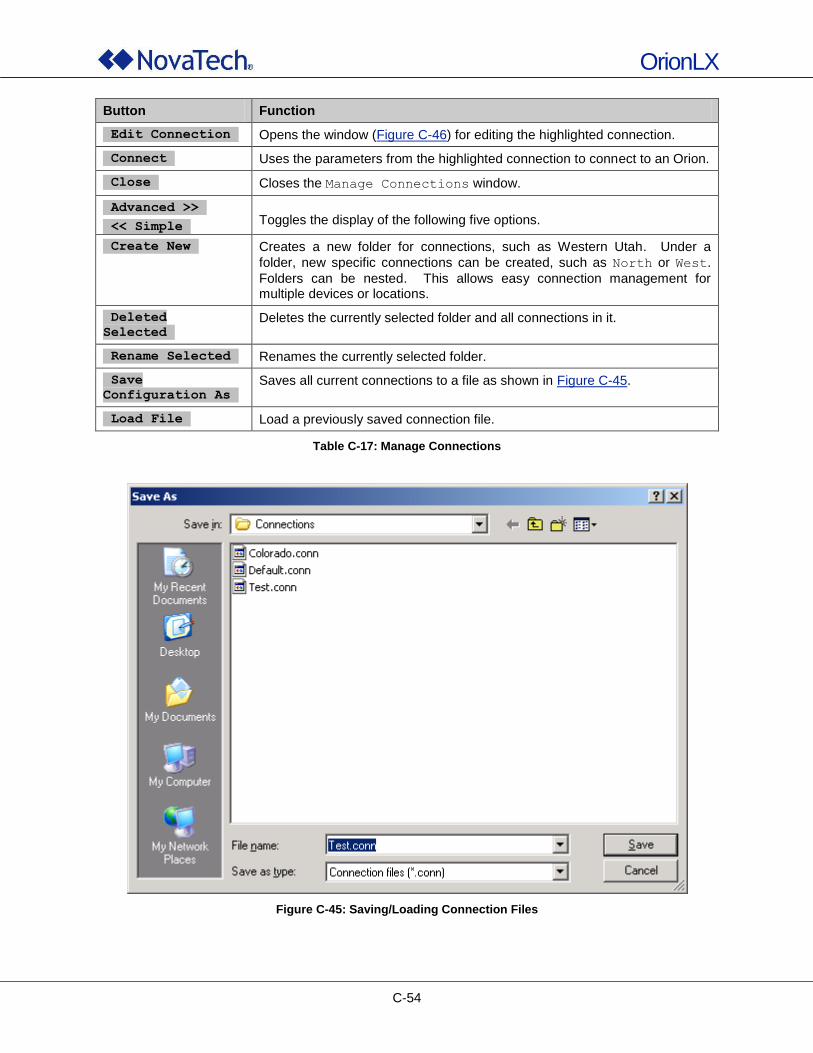
OrionLX
C-54
Button Function
Edit Connection Opens the window (Figure C-46) for editing the highlighted connection.
Connect Uses the parameters from the highlighted connection to connect to an Orion.
Close Closes the Manage Connections window.
Advanced >>
<< Simple Toggles the display of the following five options.
Create New Creates a new folder for connections, such as Western Utah. Under a
folder, new specific connections can be created, such as North or West.
Folders can be nested. This allows easy connection management for multiple devices or locations.
Deleted
Selected Deletes the currently selected folder and all connections in it.
Rename Selected Renames the currently selected folder.
Save
Configuration As Saves all current connections to a file as shown in Figure C-45.
Load File Load a previously saved connection file.
Table C-17: Manage Connections
Figure C-45: Saving/Loading Connection Files
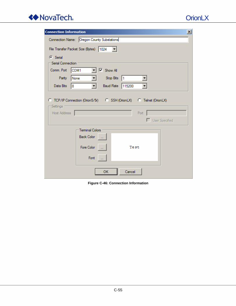
OrionLX
C-55
Figure C-46: Connection Information
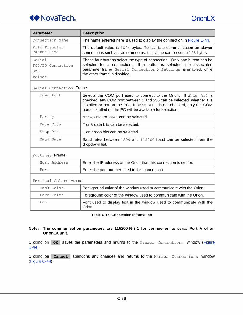
OrionLX
C-56
Parameter Description
Connection Name The name entered here is used to display the connection in Figure C-44.
File Transfer
Packet Size
The default value is 1024 bytes. To facilitate communication on slower
connections such as radio modems, this value can be set to 128 bytes.
Serial
TCP/IP Connection
SSH
Telnet
These four buttons select the type of connection. Only one button can be selected for a connection. If a button is selected, the associated
parameter frame (Serial Connection or Settings) is enabled, while
the other frame is disabled.
Serial Connection Frame
Comm Port Selects the COM port used to connect to the Orion. If Show All is
checked, any COM port between 1 and 256 can be selected, whether it is
installed or not on the PC. If Show All is not checked, only the COM
ports installed on the PC will be available for selection.
Parity None, Odd, or Even can be selected.
Data Bits 7 or 8 data bits can be selected.
Stop Bit 1 or 2 stop bits can be selected.
Baud Rate Baud rates between 1200 and 115200 baud can be selected from the
dropdown list.
Settings Frame
Host Address Enter the IP address of the Orion that this connection is set for.
Port Enter the port number used in this connection.
Terminal Colors Frame
Back Color Background color of the window used to communicate with the Orion.
Fore Color Foreground color of the window used to communicate with the Orion.
Font Font used to display text in the window used to communicate with the Orion.
Table C-18: Connection Information
Note: The communication parameters are 115200-N-8-1 for connection to serial Port A of an
OrionLX unit. Clicking on OK saves the parameters and returns to the Manage Connections window (Figure
C-44). Clicking on Cancel abandons any changes and returns to the Manage Connections window
(Figure C-44).
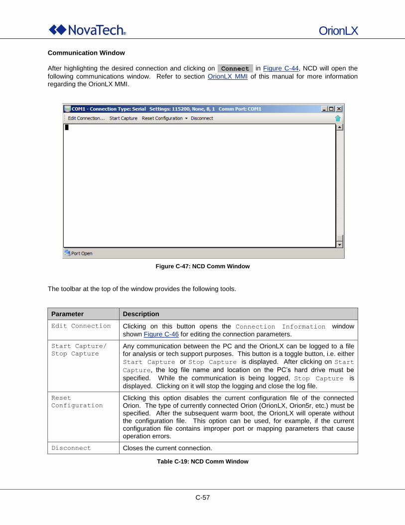
OrionLX
C-57
Communication Window After highlighting the desired connection and clicking on Connect in Figure C-44, NCD will open the
following communications window. Refer to section OrionLX MMI of this manual for more information regarding the OrionLX MMI.
Figure C-47: NCD Comm Window
The toolbar at the top of the window provides the following tools.
Parameter Description
Edit Connection Clicking on this button opens the Connection Information window
shown Figure C-46 for editing the connection parameters.
Start Capture/
Stop Capture
Any communication between the PC and the OrionLX can be logged to a file for analysis or tech support purposes. This button is a toggle button, i.e. either
Start Capture or Stop Capture is displayed. After clicking on Start
Capture, the log file name and location on the PC‟s hard drive must be
specified. While the communication is being logged, Stop Capture is
displayed. Clicking on it will stop the logging and close the log file.
Reset
Configuration
Clicking this option disables the current configuration file of the connected Orion. The type of currently connected Orion (OrionLX, Orion5r, etc.) must be specified. After the subsequent warm boot, the OrionLX will operate without the configuration file. This option can be used, for example, if the current configuration file contains improper port or mapping parameters that cause operation errors.
Disconnect Closes the current connection.
Table C-19: NCD Comm Window
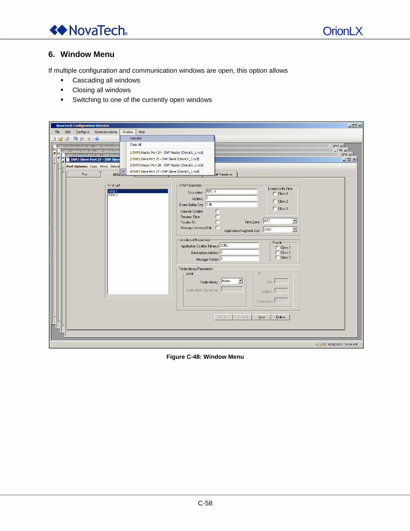
OrionLX
C-58
6. Window Menu If multiple configuration and communication windows are open, this option allows
Cascading all windows
Closing all windows
Switching to one of the currently open windows
Figure C-48: Window Menu
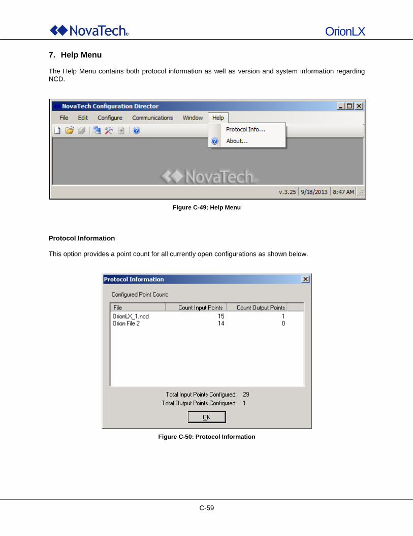
OrionLX
C-59
7. Help Menu The Help Menu contains both protocol information as well as version and system information regarding NCD.
Figure C-49: Help Menu
Protocol Information This option provides a point count for all currently open configurations as shown below.
Figure C-50: Protocol Information
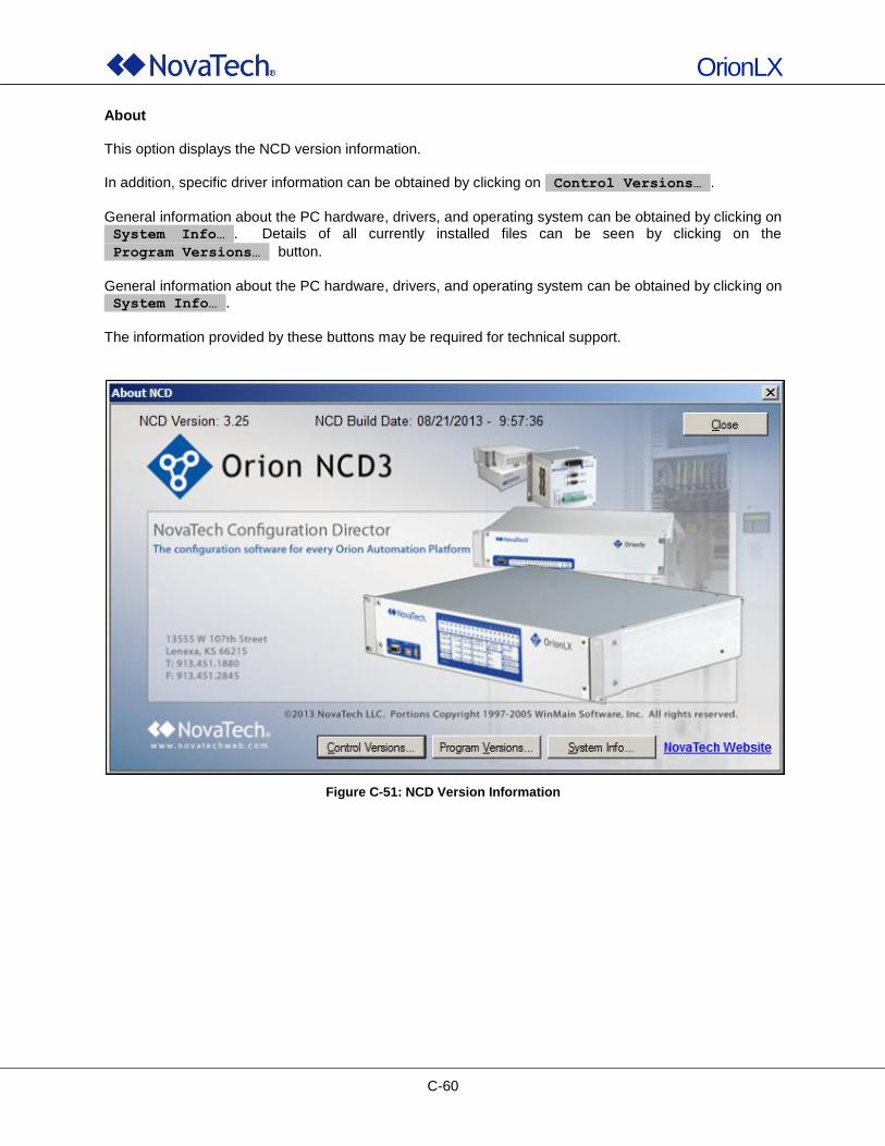
OrionLX
C-60
About This option displays the NCD version information. In addition, specific driver information can be obtained by clicking on Control Versions… .
General information about the PC hardware, drivers, and operating system can be obtained by clicking on System Info… . Details of all currently installed files can be seen by clicking on the
Program Versions… button.
General information about the PC hardware, drivers, and operating system can be obtained by clicking on System Info… .
The information provided by these buttons may be required for technical support.
Figure C-51: NCD Version Information

OrionLX
D-1
D. OrionLX Webpage
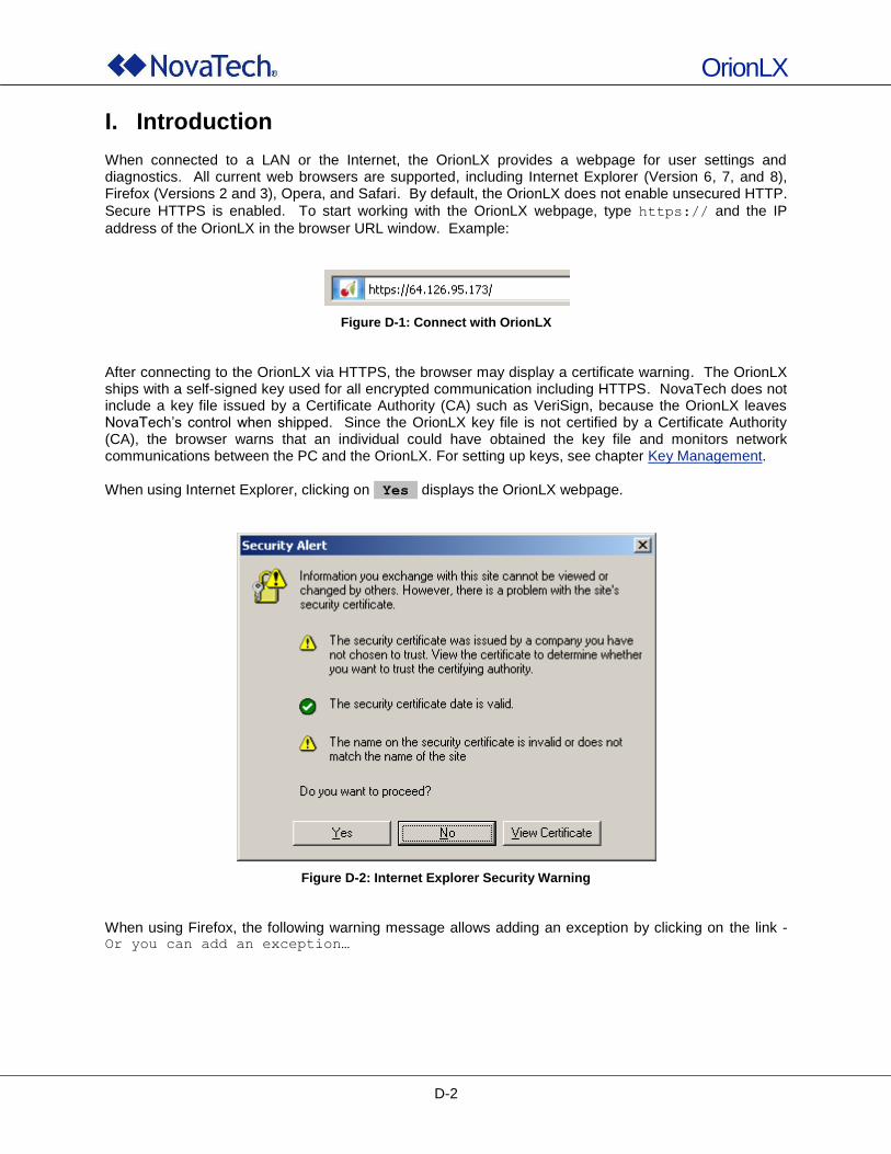
OrionLX
D-2
I. Introduction When connected to a LAN or the Internet, the OrionLX provides a webpage for user settings and diagnostics. All current web browsers are supported, including Internet Explorer (Version 6, 7, and 8), Firefox (Versions 2 and 3), Opera, and Safari. By default, the OrionLX does not enable unsecured HTTP.
Secure HTTPS is enabled. To start working with the OrionLX webpage, type https:// and the IP
address of the OrionLX in the browser URL window. Example:
Figure D-1: Connect with OrionLX
After connecting to the OrionLX via HTTPS, the browser may display a certificate warning. The OrionLX ships with a self-signed key used for all encrypted communication including HTTPS. NovaTech does not include a key file issued by a Certificate Authority (CA) such as VeriSign, because the OrionLX leaves NovaTech‟s control when shipped. Since the OrionLX key file is not certified by a Certificate Authority (CA), the browser warns that an individual could have obtained the key file and monitors network communications between the PC and the OrionLX. For setting up keys, see chapter Key Management. When using Internet Explorer, clicking on Yes displays the OrionLX webpage.
Figure D-2: Internet Explorer Security Warning
When using Firefox, the following warning message allows adding an exception by clicking on the link - Or you can add an exception…
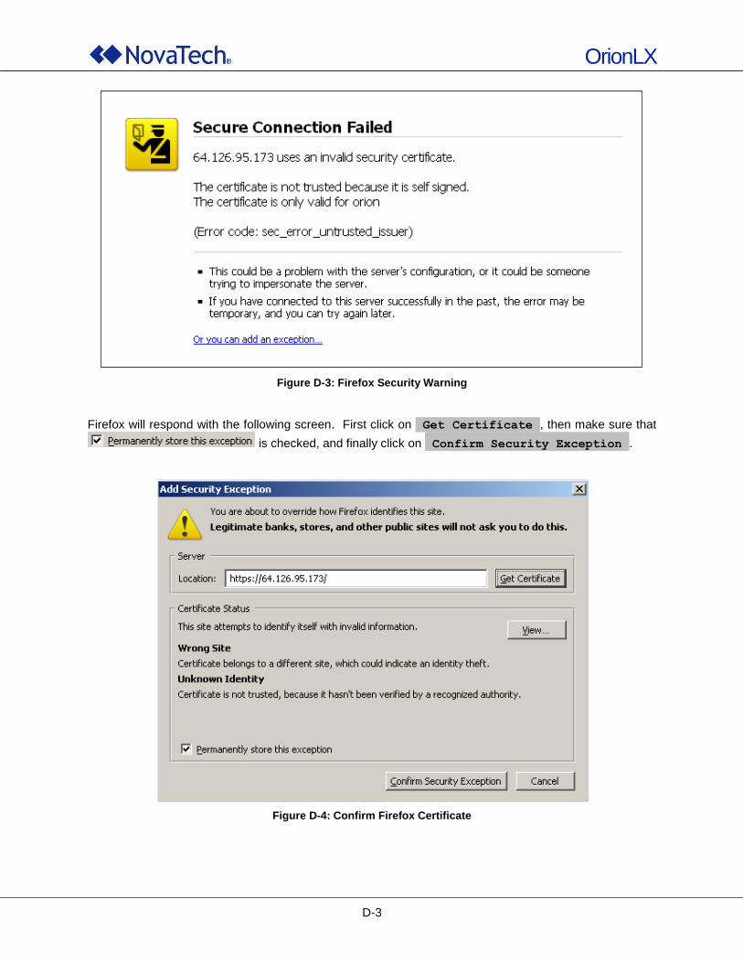
OrionLX
D-3
Figure D-3: Firefox Security Warning
Firefox will respond with the following screen. First click on Get Certificate , then make sure that
is checked, and finally click on Confirm Security Exception .
Figure D-4: Confirm Firefox Certificate
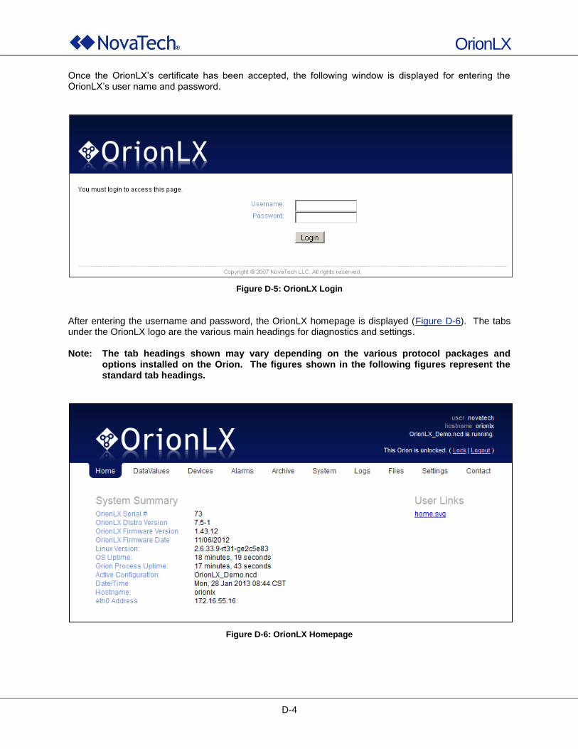
OrionLX
D-4
Once the OrionLX‟s certificate has been accepted, the following window is displayed for entering the OrionLX‟s user name and password.
Figure D-5: OrionLX Login
After entering the username and password, the OrionLX homepage is displayed (Figure D-6). The tabs under the OrionLX logo are the various main headings for diagnostics and settings. Note: The tab headings shown may vary depending on the various protocol packages and
options installed on the Orion. The figures shown in the following figures represent the standard tab headings.
Figure D-6: OrionLX Homepage
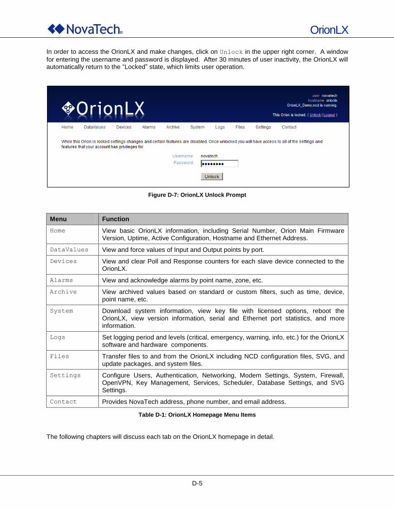
OrionLX
D-5
In order to access the OrionLX and make changes, click on Unlock in the upper right corner. A window
for entering the username and password is displayed. After 30 minutes of user inactivity, the OrionLX will automatically return to the “Locked” state, which limits user operation.
Figure D-7: OrionLX Unlock Prompt
Menu Function
Home View basic OrionLX information, including Serial Number, Orion Main Firmware Version, Uptime, Active Configuration, Hostname and Ethernet Address.
DataValues View and force values of Input and Output points by port.
Devices View and clear Poll and Response counters for each slave device connected to the OrionLX.
Alarms View and acknowledge alarms by point name, zone, etc.
Archive View archived values based on standard or custom filters, such as time, device, point name, etc.
System Download system information, view key file with licensed options, reboot the OrionLX, view version information, serial and Ethernet port statistics, and more information.
Logs Set logging period and levels (critical, emergency, warning, info, etc.) for the OrionLX software and hardware components.
Files Transfer files to and from the OrionLX including NCD configuration files, SVG, and update packages, and system files.
Settings Configure Users, Authentication, Networking, Modem Settings, System, Firewall, OpenVPN, Key Management, Services, Scheduler, Database Settings, and SVG Settings.
Contact Provides NovaTech address, phone number, and email address.
Table D-1: OrionLX Homepage Menu Items
The following chapters will discuss each tab on the OrionLX homepage in detail.
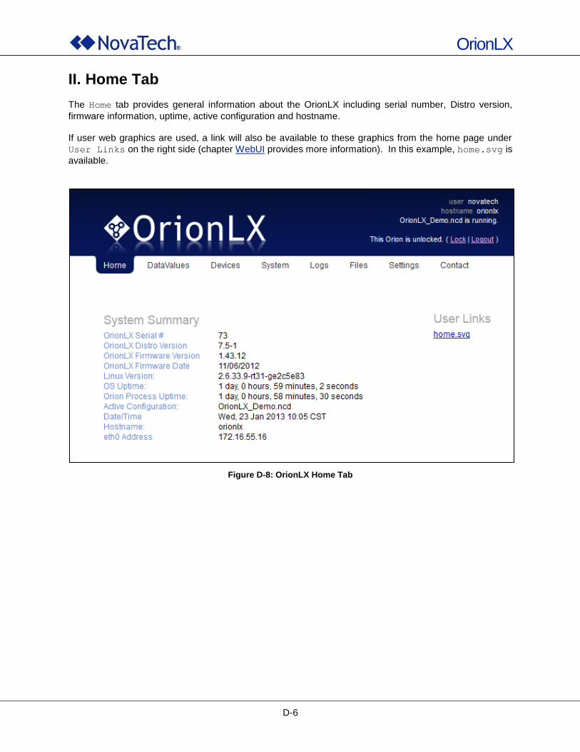
OrionLX
D-6
II. Home Tab
The Home tab provides general information about the OrionLX including serial number, Distro version,
firmware information, uptime, active configuration and hostname. If user web graphics are used, a link will also be available to these graphics from the home page under
User Links on the right side (chapter WebUI provides more information). In this example, home.svg is
available.
Figure D-8: OrionLX Home Tab
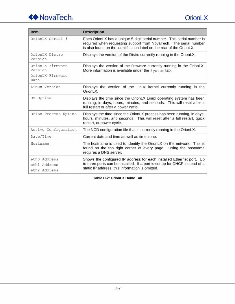
OrionLX
D-7
Item Description
OrionLX Serial # Each OrionLX has a unique 5-digit serial number. This serial number is required when requesting support from NovaTech. The serial number is also found on the identification label on the rear of the OrionLX.
OrionLX Distro
Version
Displays the version of the Distro currently running in the OrionLX.
OrionLX Firmware
Version
OrionLX Firmware
Date
Displays the version of the firmware currently running in the OrionLX.
More information is available under the System tab.
Linux Version Displays the version of the Linux kernel currently running in the OrionLX.
OS Uptime Displays the time since the OrionLX Linux operating system has been running, in days, hours, minutes, and seconds. This will reset after a full restart or after a power cycle.
Orion Process Uptime Displays the time since the OrionLX process has been running, in days, hours, minutes, and seconds. This will reset after a full restart, quick restart, or power cycle.
Active Configuration The NCD configuration file that is currently running in the OrionLX.
Date/Time Current date and time as well as time zone.
Hostname The hostname is used to identify the OrionLX on the network. This is found on the top right corner of every page. Using the hostname requires a DNS server.
eth0 Address
eth1 Address
eth2 Address
Shows the configured IP address for each installed Ethernet port. Up to three ports can be installed. If a port is set up for DHCP instead of a static IP address, this information is omitted.
Table D-2: OrionLX Home Tab
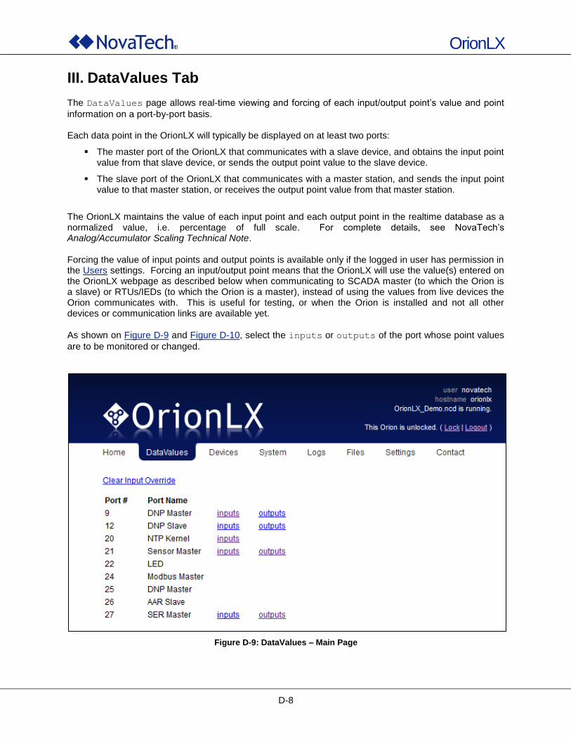
OrionLX
D-8
III. DataValues Tab
The DataValues page allows real-time viewing and forcing of each input/output point‟s value and point
information on a port-by-port basis. Each data point in the OrionLX will typically be displayed on at least two ports:
The master port of the OrionLX that communicates with a slave device, and obtains the input point value from that slave device, or sends the output point value to the slave device.
The slave port of the OrionLX that communicates with a master station, and sends the input point value to that master station, or receives the output point value from that master station.
The OrionLX maintains the value of each input point and each output point in the realtime database as a normalized value, i.e. percentage of full scale. For complete details, see NovaTech‟s Analog/Accumulator Scaling Technical Note. Forcing the value of input points and output points is available only if the logged in user has permission in the Users settings. Forcing an input/output point means that the OrionLX will use the value(s) entered on the OrionLX webpage as described below when communicating to SCADA master (to which the Orion is a slave) or RTUs/IEDs (to which the Orion is a master), instead of using the values from live devices the Orion communicates with. This is useful for testing, or when the Orion is installed and not all other devices or communication links are available yet.
As shown on Figure D-9 and Figure D-10, select the inputs or outputs of the port whose point values
are to be monitored or changed.
Figure D-9: DataValues – Main Page
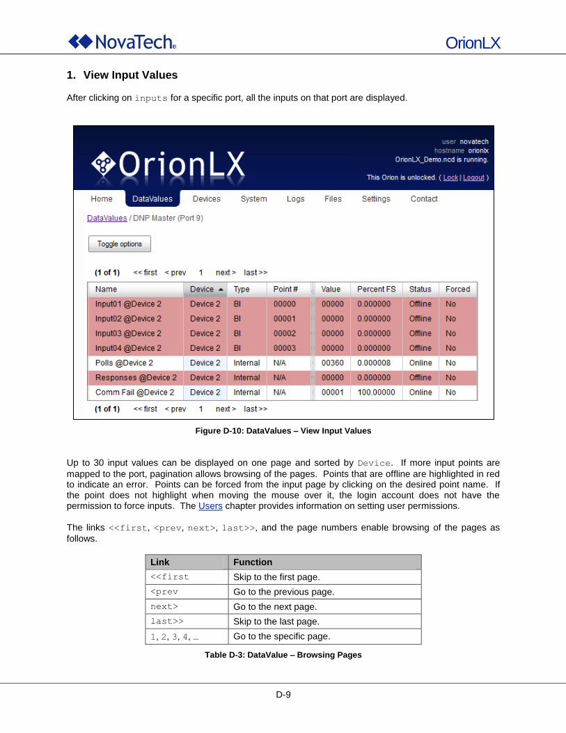
OrionLX
D-9
1. View Input Values
After clicking on inputs for a specific port, all the inputs on that port are displayed.
Figure D-10: DataValues – View Input Values
Up to 30 input values can be displayed on one page and sorted by Device. If more input points are
mapped to the port, pagination allows browsing of the pages. Points that are offline are highlighted in red to indicate an error. Points can be forced from the input page by clicking on the desired point name. If the point does not highlight when moving the mouse over it, the login account does not have the permission to force inputs. The Users chapter provides information on setting user permissions.
The links <<first, <prev, next>, last>>, and the page numbers enable browsing of the pages as
follows.
Link Function
<<first Skip to the first page.
<prev Go to the previous page.
next> Go to the next page.
last>> Skip to the last page.
1, 2, 3, 4, … Go to the specific page.
Table D-3: DataValue – Browsing Pages
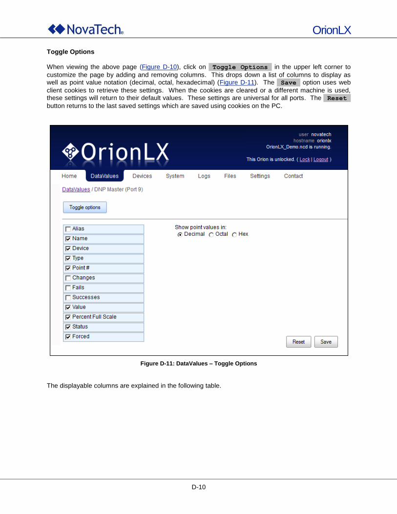
OrionLX
D-10
Toggle Options When viewing the above page (Figure D-10), click on Toggle Options in the upper left corner to
customize the page by adding and removing columns. This drops down a list of columns to display as well as point value notation (decimal, octal, hexadecimal) (Figure D-11). The Save option uses web
client cookies to retrieve these settings. When the cookies are cleared or a different machine is used, these settings will return to their default values. These settings are universal for all ports. The Reset
button returns to the last saved settings which are saved using cookies on the PC.
Figure D-11: DataValues – Toggle Options
The displayable columns are explained in the following table.
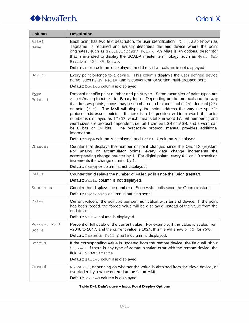
OrionLX
D-11
Column Description
Alias
Name
Each point has two text descriptors for user identification. Name, also known as
Tagname, is required and usually describes the end device where the point
originates, such as Breaker424@HV Relay. An Alias is an optional descriptor
that is intended to display the SCADA master terminology, such as West Sub
Breaker 424 HV Relay.
Default: Name column is displayed, and the Alias column is not displayed.
Device Every point belongs to a device. This column displays the user defined device
name, such as HV Relay, and is convenient for sorting multi-dropped ports.
Default: Device column is displayed.
Type
Point #
Protocol-specific point number and point type. Some examples of point types are
AI for Analog Input, BI for Binary Input. Depending on the protocol and the way
it addresses points, points may be numbered in hexadecimal (17h), decimal (23),
or octal (27o). The MMI will display the point address the way the specific
protocol addresses points. If there is a bit position within a word, the point
number is displayed as 17:03, which means bit 3 in word 17. Bit numbering and
word sizes are protocol dependent, i.e. bit 1 can be LSB or MSB, and a word can be 8 bits or 16 bits. The respective protocol manual provides additional information.
Default: Type column is displayed, and Point # column is displayed.
Changes Counter that displays the number of point changes since the OrionLX (re)start. For analog or accumulator points, every data change increments the corresponding change counter by 1. For digital points, every 0-1 or 1-0 transition increments the change counter by 1.
Default: Changes column is not displayed.
Fails Counter that displays the number of Failed polls since the Orion (re)start.
Default: Fails column is not displayed.
Successes Counter that displays the number of Successful polls since the Orion (re)start.
Default: Successes column is not displayed.
Value Current value of the point as per communication with an end device. If the point has been forced, the forced value will be displayed instead of the value from the end device.
Default: Value column is displayed.
Percent Full
Scale
Percent of full scale of the current value. For example, if the value is scaled from
–2048 to 2047, and the current value is 1024, this file will show 0.75 for 75%.
Default: Percent Full Scale column is displayed.
Status If the corresponding value is updated from the remote device, the field will show
Online. If there is any type of communication error with the remote device, the
field will show Offline.
Default: Status column is displayed.
Forced No or Yes, depending on whether the value is obtained from the slave device, or
overridden by a value entered at the Orion MMI.
Default: Forced column is displayed.
Table D-4: DataValues – Input Point Display Options
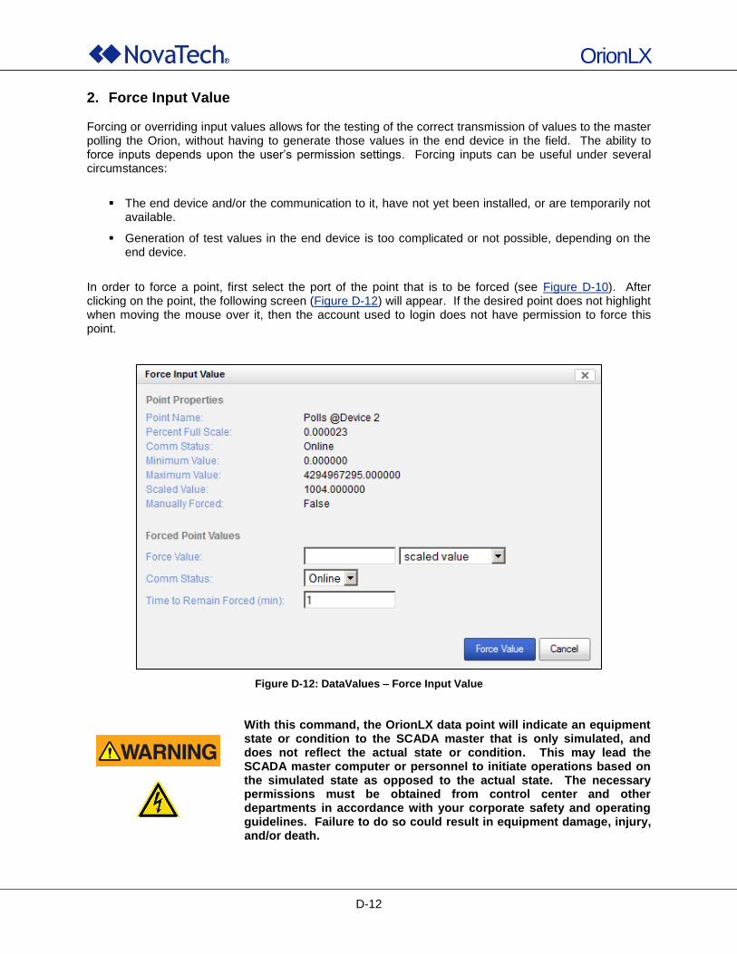
OrionLX
D-12
2. Force Input Value Forcing or overriding input values allows for the testing of the correct transmission of values to the master polling the Orion, without having to generate those values in the end device in the field. The ability to force inputs depends upon the user‟s permission settings. Forcing inputs can be useful under several circumstances:
The end device and/or the communication to it, have not yet been installed, or are temporarily not available.
Generation of test values in the end device is too complicated or not possible, depending on the end device.
In order to force a point, first select the port of the point that is to be forced (see Figure D-10). After clicking on the point, the following screen (Figure D-12) will appear. If the desired point does not highlight when moving the mouse over it, then the account used to login does not have permission to force this point.
Figure D-12: DataValues – Force Input Value
With this command, the OrionLX data point will indicate an equipment state or condition to the SCADA master that is only simulated, and does not reflect the actual state or condition. This may lead the SCADA master computer or personnel to initiate operations based on the simulated state as opposed to the actual state. The necessary permissions must be obtained from control center and other departments in accordance with your corporate safety and operating guidelines. Failure to do so could result in equipment damage, injury, and/or death.
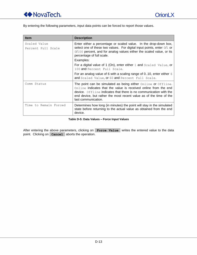
OrionLX
D-13
By entering the following parameters, input data points can be forced to report those values.
Item Description
Scaled Value
Percent Full Scale
Enter either a percentage or scaled value. In the drop-down box,
select one of these two values. For digital input points, enter 0/1 or
0/100 percent, and for analog values either the scaled value, or its
percentage of full scale.
Examples:
For a digital value of 1 (On), enter either 1 and Scaled Value, or
100 and Percent Full Scale.
For an analog value of 6 with a scaling range of 0..10, enter either 6
and Scaled Value, or 60 and Percent Full Scale.
Comm Status The point can be simulated as being either Online or Offline.
Online indicates that the value is received online from the end
device. Offline indicates that there is no communication with the
end device, but rather the most recent value as of the time of the last communication.
Time to Remain Forced Determines how long (in minutes) the point will stay in the simulated state before returning to the actual value as obtained from the end device.
Table D-5: Data Values – Force Input Values
After entering the above parameters, clicking on Force Value writes the entered value to the data
point. Clicking on Cancel aborts the operation.
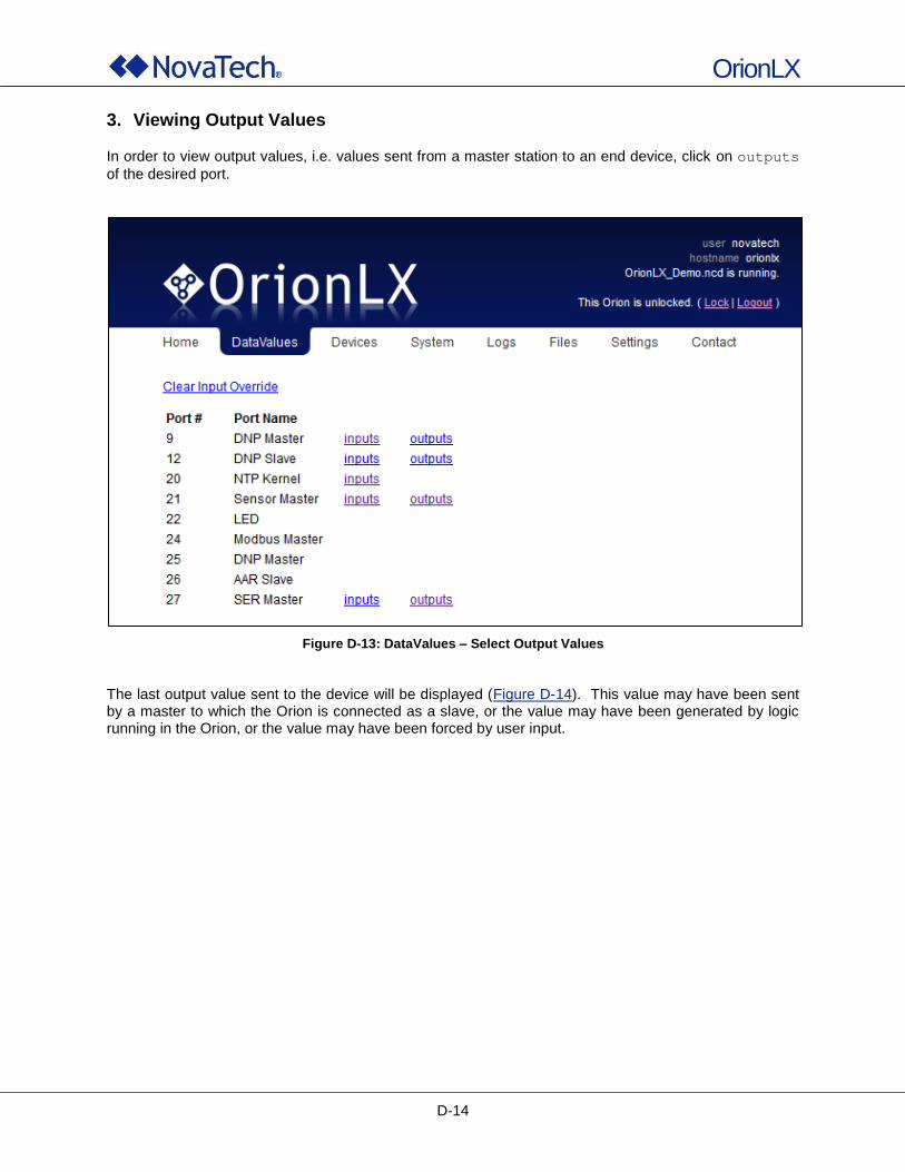
OrionLX
D-14
3. Viewing Output Values
In order to view output values, i.e. values sent from a master station to an end device, click on outputs
of the desired port.
Figure D-13: DataValues – Select Output Values
The last output value sent to the device will be displayed (Figure D-14). This value may have been sent by a master to which the Orion is connected as a slave, or the value may have been generated by logic running in the Orion, or the value may have been forced by user input.
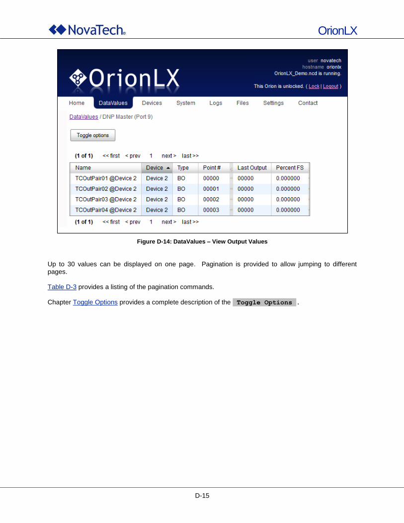
OrionLX
D-15
Figure D-14: DataValues – View Output Values
Up to 30 values can be displayed on one page. Pagination is provided to allow jumping to different pages. Table D-3 provides a listing of the pagination commands. Chapter Toggle Options provides a complete description of the Toggle Options .
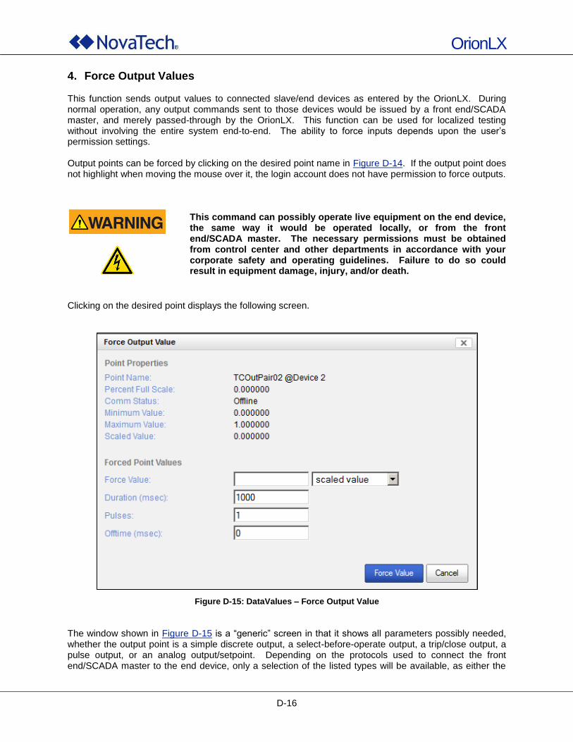
OrionLX
D-16
4. Force Output Values This function sends output values to connected slave/end devices as entered by the OrionLX. During normal operation, any output commands sent to those devices would be issued by a front end/SCADA master, and merely passed-through by the OrionLX. This function can be used for localized testing without involving the entire system end-to-end. The ability to force inputs depends upon the user‟s permission settings. Output points can be forced by clicking on the desired point name in Figure D-14. If the output point does not highlight when moving the mouse over it, the login account does not have permission to force outputs.
This command can possibly operate live equipment on the end device,
the same way it would be operated locally, or from the front end/SCADA master. The necessary permissions must be obtained from control center and other departments in accordance with your corporate safety and operating guidelines. Failure to do so could result in equipment damage, injury, and/or death.
Clicking on the desired point displays the following screen.
Figure D-15: DataValues – Force Output Value
The window shown in Figure D-15 is a “generic” screen in that it shows all parameters possibly needed, whether the output point is a simple discrete output, a select-before-operate output, a trip/close output, a pulse output, or an analog output/setpoint. Depending on the protocols used to connect the front end/SCADA master to the end device, only a selection of the listed types will be available, as either the
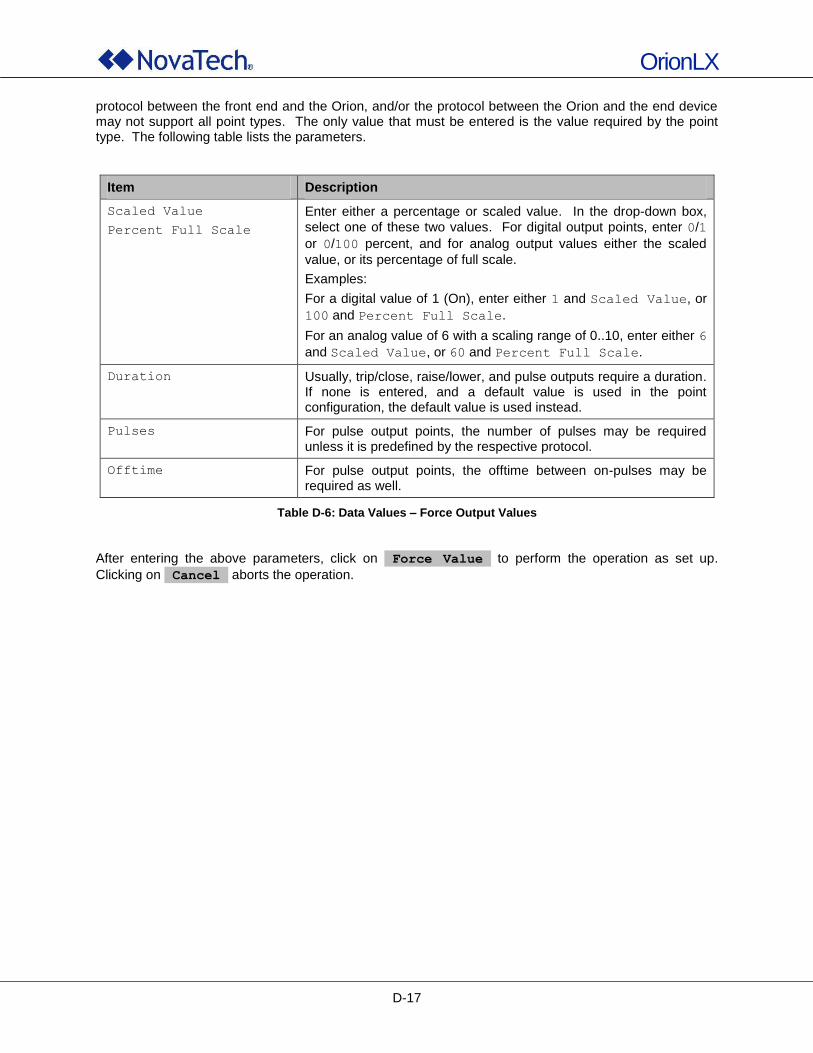
OrionLX
D-17
protocol between the front end and the Orion, and/or the protocol between the Orion and the end device may not support all point types. The only value that must be entered is the value required by the point type. The following table lists the parameters.
Item Description
Scaled Value
Percent Full Scale
Enter either a percentage or scaled value. In the drop-down box,
select one of these two values. For digital output points, enter 0/1
or 0/100 percent, and for analog output values either the scaled
value, or its percentage of full scale.
Examples:
For a digital value of 1 (On), enter either 1 and Scaled Value, or
100 and Percent Full Scale.
For an analog value of 6 with a scaling range of 0..10, enter either 6
and Scaled Value, or 60 and Percent Full Scale.
Duration Usually, trip/close, raise/lower, and pulse outputs require a duration. If none is entered, and a default value is used in the point configuration, the default value is used instead.
Pulses For pulse output points, the number of pulses may be required unless it is predefined by the respective protocol.
Offtime For pulse output points, the offtime between on-pulses may be required as well.
Table D-6: Data Values – Force Output Values
After entering the above parameters, click on Force Value to perform the operation as set up.
Clicking on Cancel aborts the operation.
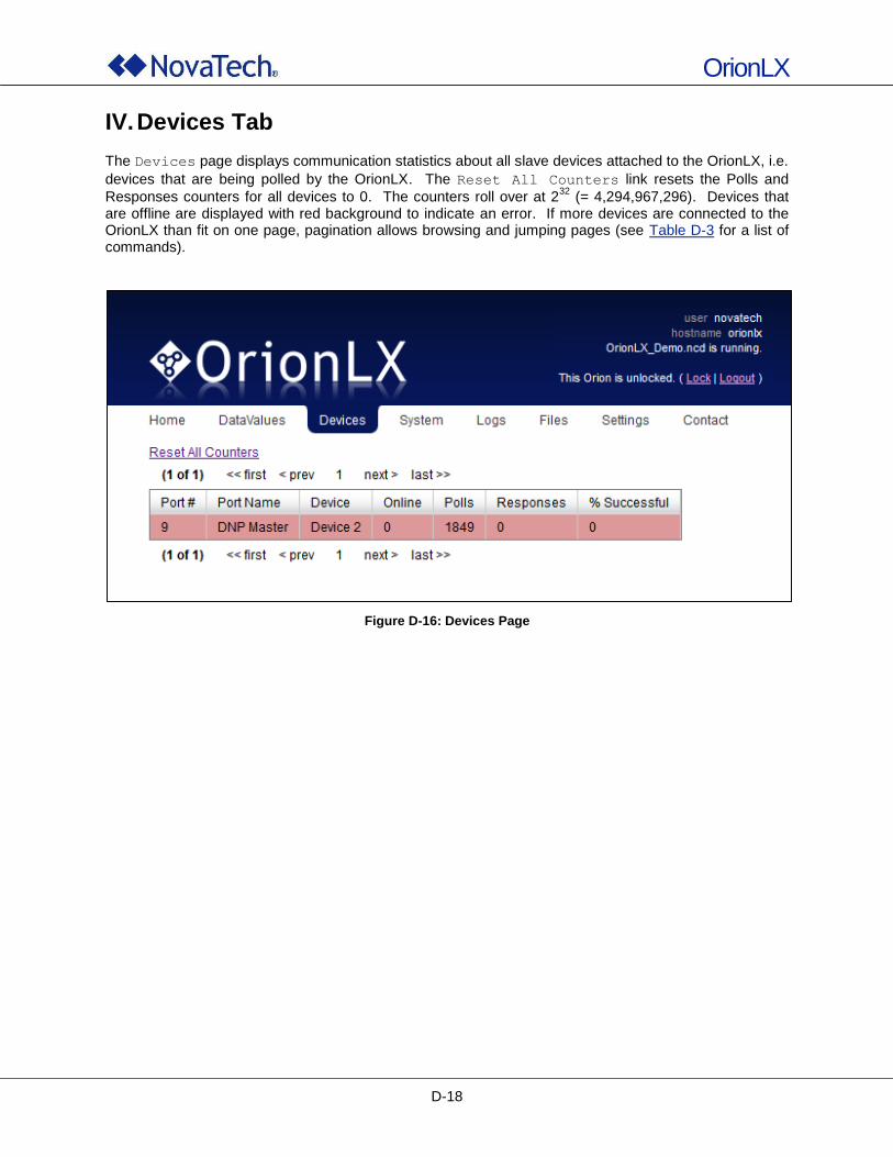
OrionLX
D-18
IV. Devices Tab
The Devices page displays communication statistics about all slave devices attached to the OrionLX, i.e.
devices that are being polled by the OrionLX. The Reset All Counters link resets the Polls and
Responses counters for all devices to 0. The counters roll over at 232
(= 4,294,967,296). Devices that are offline are displayed with red background to indicate an error. If more devices are connected to the OrionLX than fit on one page, pagination allows browsing and jumping pages (see Table D-3 for a list of commands).
Figure D-16: Devices Page
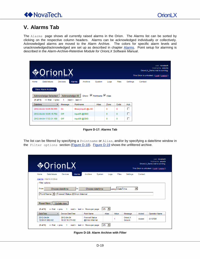
OrionLX
D-19
V. Alarms Tab
The Alarms page shows all currently raised alarms in the Orion. The Alarms list can be sorted by
clicking on the respective column headers. Alarms can be acknowledged individually or collectively. Acknowledged alarms are moved to the Alarm Archive. The colors for specific alarm levels and unacknowledged/acknowledged are set up as described in chapter Alarms. Point setup for alarming is described in the Alarm-Archive-Retentive Module for OrionLX Software Manual.
Figure D-17: Alarms Tab
The list can be filtered by specifying a Pointname or Alias, and/or by specifying a date/time window in
the Filter options section (Figure D-18). Figure D-19 shows the unfiltered archive.
Figure D-18: Alarm Archive with Filter
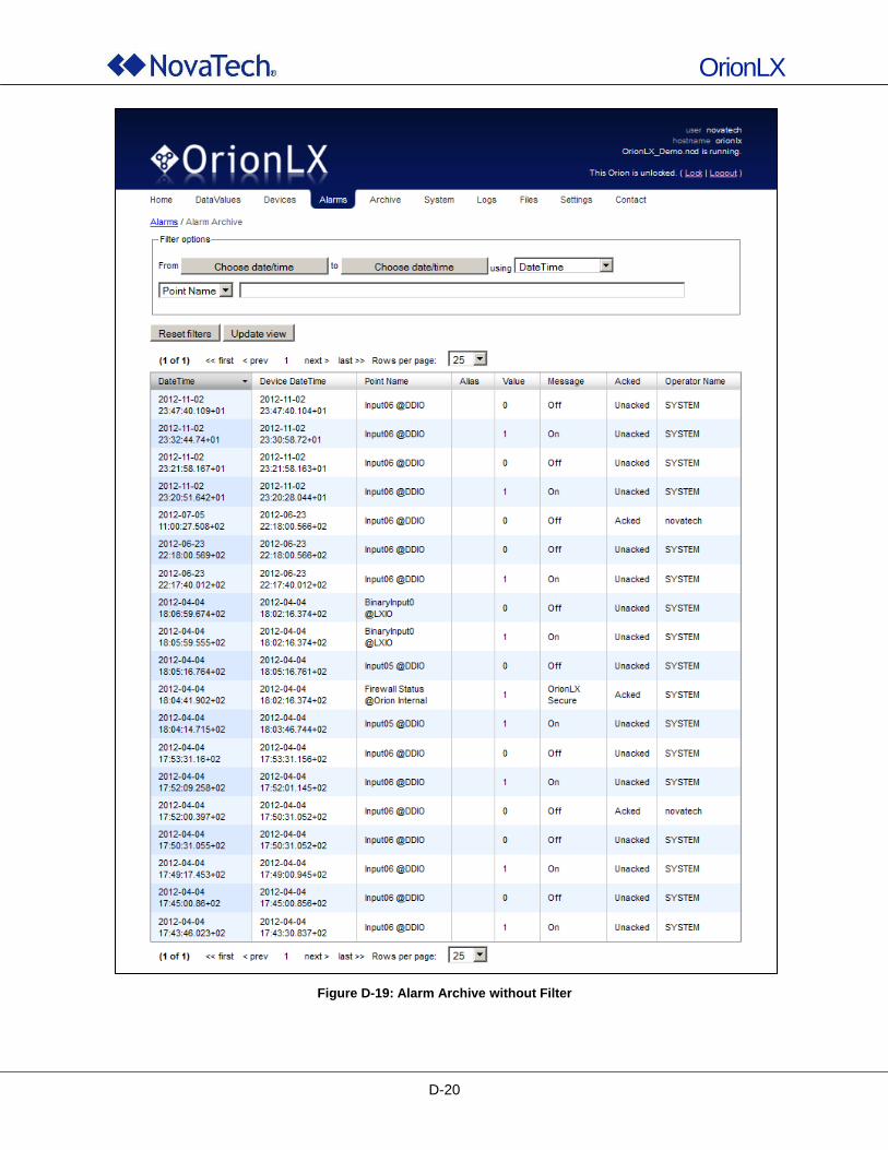
OrionLX
D-20
Figure D-19: Alarm Archive without Filter
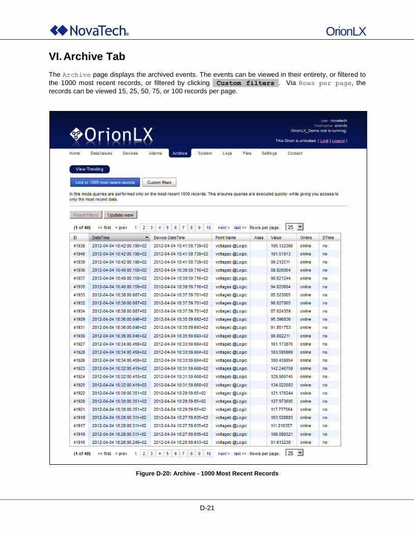
OrionLX
D-21
VI. Archive Tab
The Archive page displays the archived events. The events can be viewed in their entirety, or filtered to
the 1000 most recent records, or filtered by clicking Custom filters . Via Rows per page, the
records can be viewed 15, 25, 50, 75, or 100 records per page.
Figure D-20: Archive - 1000 Most Recent Records
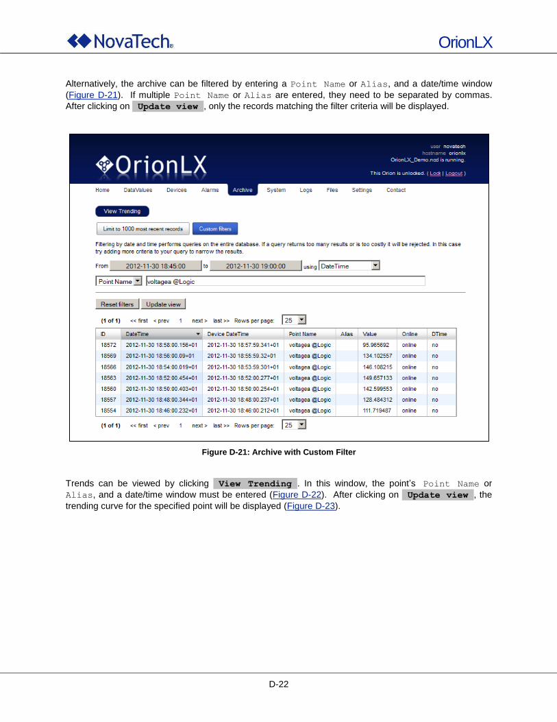
OrionLX
D-22
Alternatively, the archive can be filtered by entering a Point Name or Alias, and a date/time window
(Figure D-21). If multiple Point Name or Alias are entered, they need to be separated by commas.
After clicking on Update view , only the records matching the filter criteria will be displayed.
Figure D-21: Archive with Custom Filter
Trends can be viewed by clicking View Trending . In this window, the point‟s Point Name or
Alias, and a date/time window must be entered (Figure D-22). After clicking on Update view , the
trending curve for the specified point will be displayed (Figure D-23).
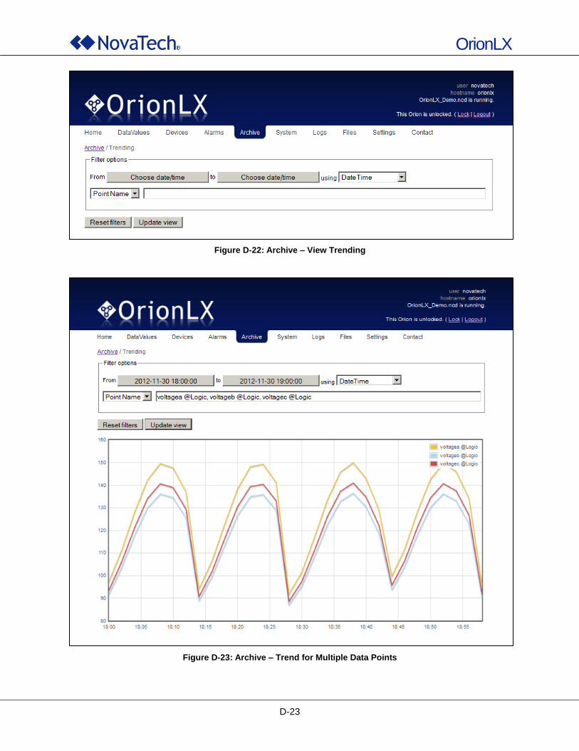
OrionLX
D-23
Figure D-22: Archive – View Trending
Figure D-23: Archive – Trend for Multiple Data Points
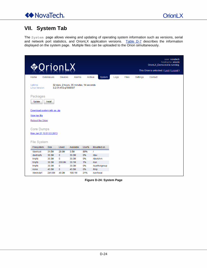
OrionLX
D-24
VII. System Tab
The System page allows viewing and updating of operating system information such as versions, serial
and network port statistics, and OrionLX application versions. Table D-7 describes the information displayed on the system page. Multiple files can be uploaded to the Orion simultaneously.
Figure D-24: System Page
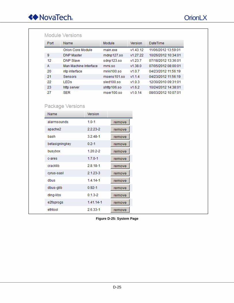
OrionLX
D-25
Figure D-25: System Page
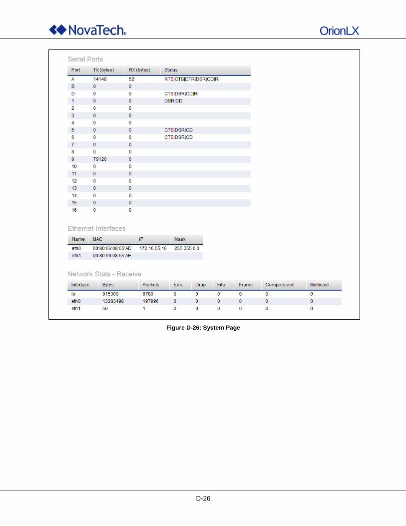
OrionLX
D-26
Figure D-26: System Page
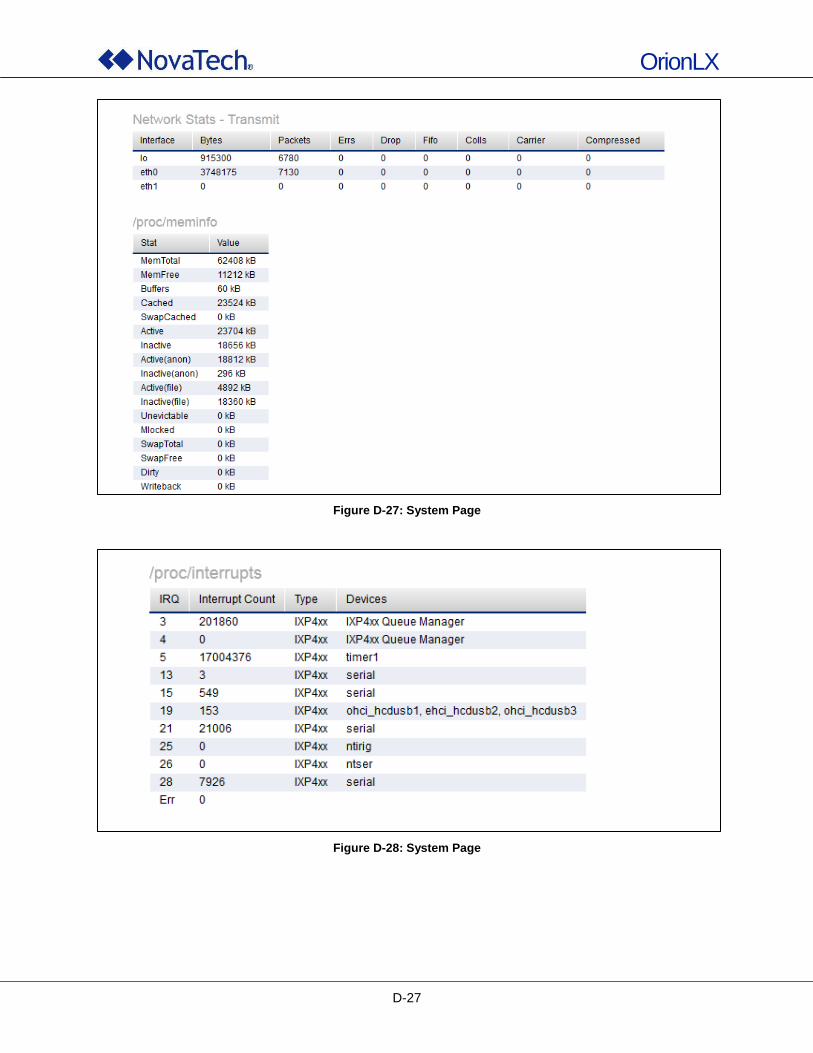
OrionLX
D-27
Figure D-27: System Page
Figure D-28: System Page
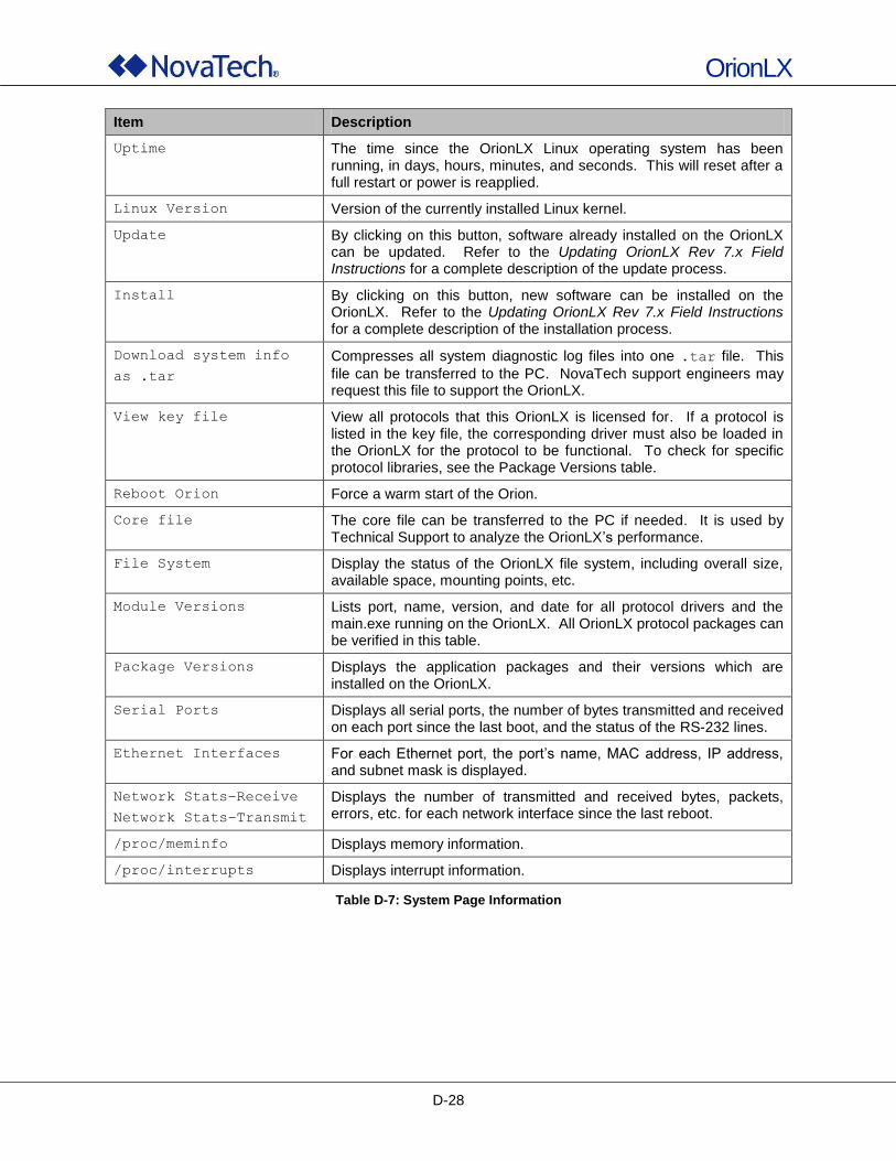
OrionLX
D-28
Item Description
Uptime The time since the OrionLX Linux operating system has been running, in days, hours, minutes, and seconds. This will reset after a full restart or power is reapplied.
Linux Version Version of the currently installed Linux kernel.
Update By clicking on this button, software already installed on the OrionLX can be updated. Refer to the Updating OrionLX Rev 7.x Field Instructions for a complete description of the update process.
Install By clicking on this button, new software can be installed on the OrionLX. Refer to the Updating OrionLX Rev 7.x Field Instructions for a complete description of the installation process.
Download system info
as .tar
Compresses all system diagnostic log files into one .tar file. This
file can be transferred to the PC. NovaTech support engineers may request this file to support the OrionLX.
View key file View all protocols that this OrionLX is licensed for. If a protocol is listed in the key file, the corresponding driver must also be loaded in the OrionLX for the protocol to be functional. To check for specific protocol libraries, see the Package Versions table.
Reboot Orion Force a warm start of the Orion.
Core file The core file can be transferred to the PC if needed. It is used by Technical Support to analyze the OrionLX‟s performance.
File System Display the status of the OrionLX file system, including overall size, available space, mounting points, etc.
Module Versions Lists port, name, version, and date for all protocol drivers and the main.exe running on the OrionLX. All OrionLX protocol packages can be verified in this table.
Package Versions Displays the application packages and their versions which are installed on the OrionLX.
Serial Ports Displays all serial ports, the number of bytes transmitted and received on each port since the last boot, and the status of the RS-232 lines.
Ethernet Interfaces For each Ethernet port, the port‟s name, MAC address, IP address, and subnet mask is displayed.
Network Stats–Receive
Network Stats–Transmit
Displays the number of transmitted and received bytes, packets, errors, etc. for each network interface since the last reboot.
/proc/meminfo Displays memory information.
/proc/interrupts Displays interrupt information.
Table D-7: System Page Information
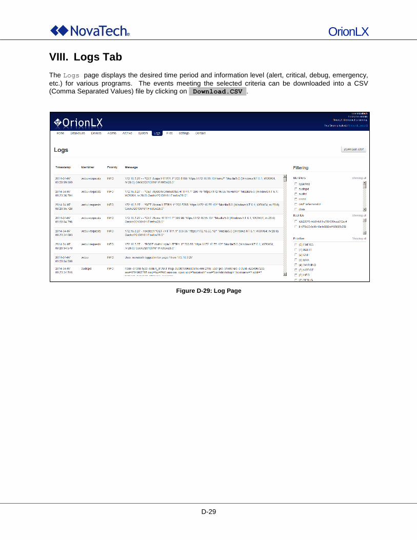
OrionLX
D-29
VIII. Logs Tab
The Logs page displays the desired time period and information level (alert, critical, debug, emergency,
etc.) for various programs. The events meeting the selected criteria can be downloaded into a CSV (Comma Separated Values) file by clicking on Download.CSV .
Figure D-29: Log Page
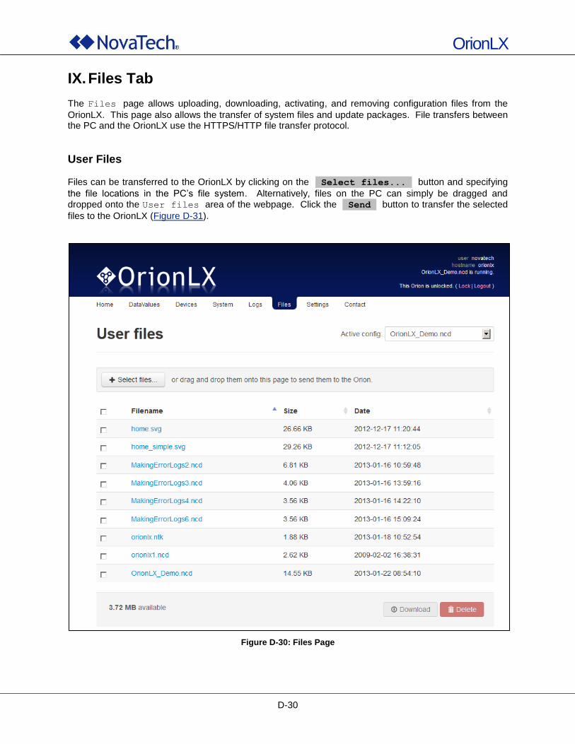
OrionLX
D-30
IX. Files Tab
The Files page allows uploading, downloading, activating, and removing configuration files from the
OrionLX. This page also allows the transfer of system files and update packages. File transfers between the PC and the OrionLX use the HTTPS/HTTP file transfer protocol.
User Files Files can be transferred to the OrionLX by clicking on the Select files... button and specifying
the file locations in the PC‟s file system. Alternatively, files on the PC can simply be dragged and dropped onto the User files area of the webpage. Click the Send button to transfer the selected
files to the OrionLX (Figure D-31).
Figure D-30: Files Page
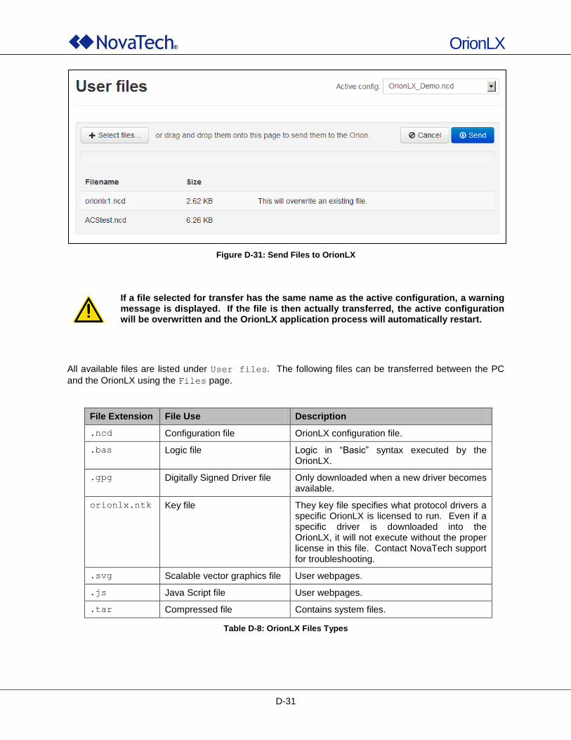
OrionLX
D-31
Figure D-31: Send Files to OrionLX
If a file selected for transfer has the same name as the active configuration, a warning message is displayed. If the file is then actually transferred, the active configuration will be overwritten and the OrionLX application process will automatically restart.
All available files are listed under User files. The following files can be transferred between the PC
and the OrionLX using the Files page.
File Extension File Use Description
.ncd Configuration file OrionLX configuration file.
.bas Logic file Logic in “Basic” syntax executed by the OrionLX.
.gpg Digitally Signed Driver file Only downloaded when a new driver becomes available.
orionlx.ntk Key file They key file specifies what protocol drivers a specific OrionLX is licensed to run. Even if a specific driver is downloaded into the OrionLX, it will not execute without the proper license in this file. Contact NovaTech support for troubleshooting.
.svg Scalable vector graphics file User webpages.
.js Java Script file User webpages.
.tar Compressed file Contains system files.
Table D-8: OrionLX Files Types
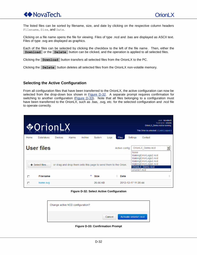
OrionLX
D-32
The listed files can be sorted by filename, size, and date by clicking on the respective column headers
Filename, Size, and Date.
Clicking on a file name opens the file for viewing. Files of type .ncd and .bas are displayed as ASCII text. Files of type .svg are displayed as graphics. Each of the files can be selected by clicking the checkbox to the left of the file name. Then, either the Download or the Delete button can be clicked, and the operation is applied to all selected files.
Clicking the Download button transfers all selected files from the OrionLX to the PC.
Clicking the Delete button deletes all selected files from the OrionLX non-volatile memory.
Selecting the Active Configuration From all configuration files that have been transferred to the OrionLX, the active configuration can now be selected from the drop-down box shown in Figure D-32. A separate prompt requires confirmation for switching to another configuration (Figure D-33). Note that all files belonging to a configuration must have been transferred to the OrionLX, such as .bas, .svg, etc. for the selected configuration and .ncd file to operate correctly.
Figure D-32: Select Active Configuration
Figure D-33: Confirmation Prompt
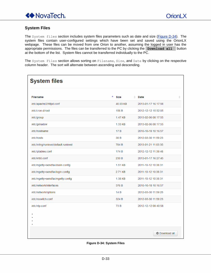
OrionLX
D-33
System Files
The System files section includes system files parameters such as date and size (Figure D-34). The
system files contain user-configured settings which have been set and saved using the OrionLX webpage. These files can be moved from one Orion to another, assuming the logged in user has the appropriate permissions. The files can be transferred to the PC by clicking the Download all button
at the bottom of the list. System files cannot be transferred individually to the PC.
The System Files section allows sorting on Filename, Size, and Date by clicking on the respective
column header. The sort will alternate between ascending and descending.
Figure D-34: System Files
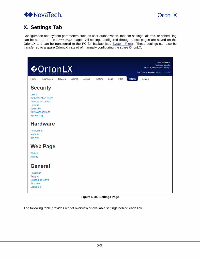
OrionLX
D-34
X. Settings Tab Configuration and system parameters such as user authorization, modem settings, alarms, or scheduling
can be set up on the Settings page. All settings configured through these pages are saved on the
OrionLX and can be transferred to the PC for backup (see System Files). These settings can also be transferred to a spare OrionLX instead of manually configuring the spare OrionLX.
Figure D-35: Settings Page
The following table provides a brief overview of available settings behind each link.
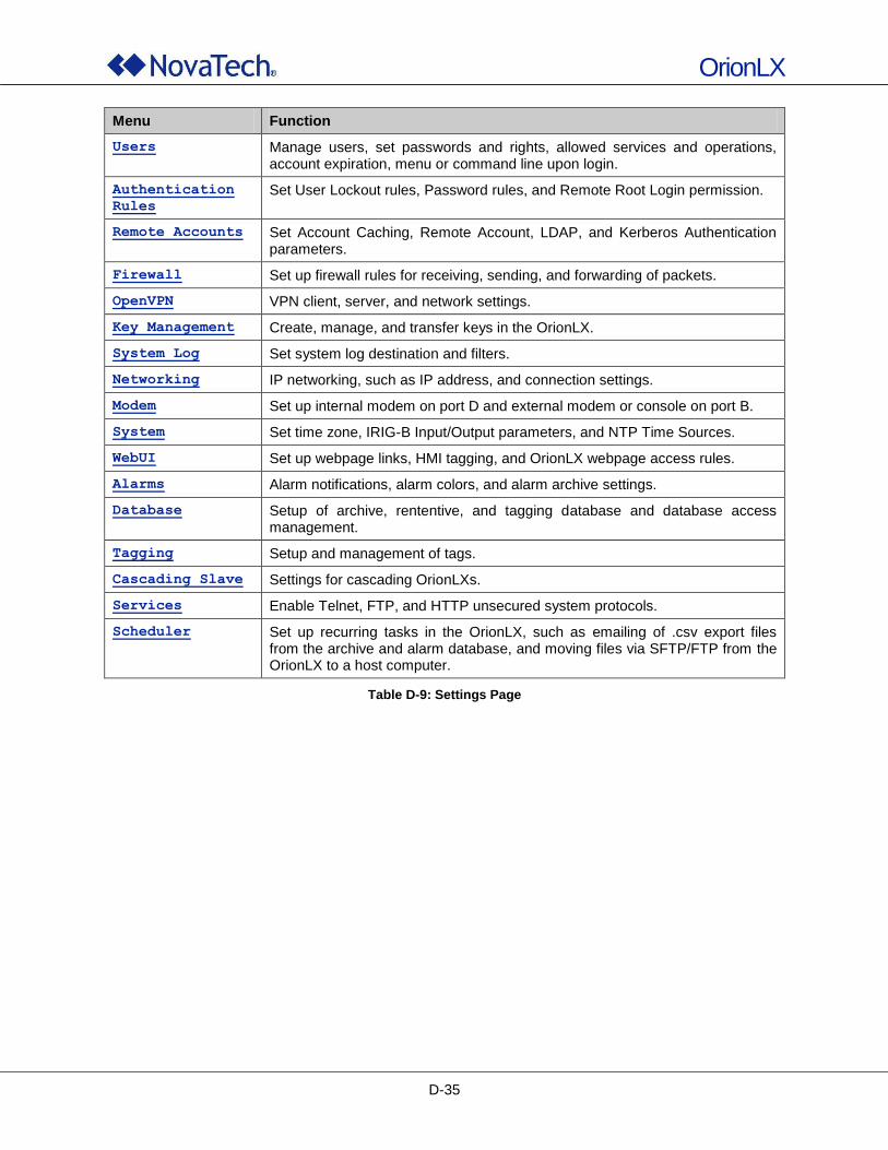
OrionLX
D-35
Menu Function
Users Manage users, set passwords and rights, allowed services and operations, account expiration, menu or command line upon login.
Authentication
Rules Set User Lockout rules, Password rules, and Remote Root Login permission.
Remote Accounts Set Account Caching, Remote Account, LDAP, and Kerberos Authentication parameters.
Firewall Set up firewall rules for receiving, sending, and forwarding of packets.
OpenVPN VPN client, server, and network settings.
Key Management Create, manage, and transfer keys in the OrionLX.
System Log Set system log destination and filters.
Networking IP networking, such as IP address, and connection settings.
Modem Set up internal modem on port D and external modem or console on port B.
System Set time zone, IRIG-B Input/Output parameters, and NTP Time Sources.
WebUI Set up webpage links, HMI tagging, and OrionLX webpage access rules.
Alarms Alarm notifications, alarm colors, and alarm archive settings.
Database Setup of archive, rententive, and tagging database and database access management.
Tagging Setup and management of tags.
Cascading Slave Settings for cascading OrionLXs.
Services Enable Telnet, FTP, and HTTP unsecured system protocols.
Scheduler Set up recurring tasks in the OrionLX, such as emailing of .csv export files from the archive and alarm database, and moving files via SFTP/FTP from the OrionLX to a host computer.
Table D-9: Settings Page
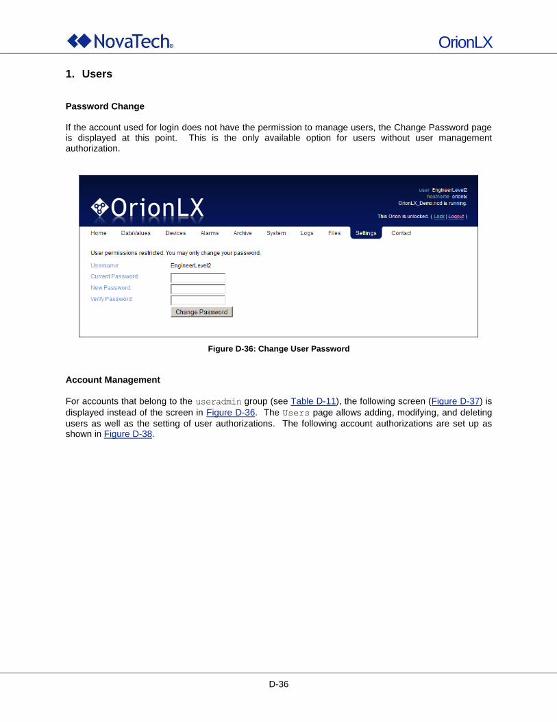
OrionLX
D-36
1. Users Password Change If the account used for login does not have the permission to manage users, the Change Password page is displayed at this point. This is the only available option for users without user management authorization.
Figure D-36: Change User Password
Account Management
For accounts that belong to the useradmin group (see Table D-11), the following screen (Figure D-37) is
displayed instead of the screen in Figure D-36. The Users page allows adding, modifying, and deleting
users as well as the setting of user authorizations. The following account authorizations are set up as shown in Figure D-38.
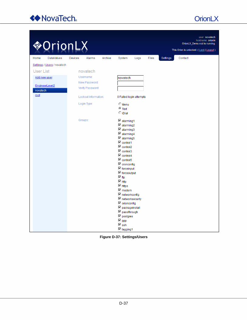
OrionLX
D-37
Figure D-37: Settings/Users
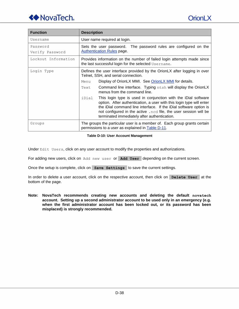
OrionLX
D-38
Function Description
Username User name required at login.
Password
Verify Password
Sets the user password. The password rules are configured on the Authentication Rules page.
Lockout Information Provides information on the number of failed login attempts made since
the last successful login for the selected Username.
Login Type Defines the user interface provided by the OrionLX after logging in over Telnet, SSH, and serial connection.
Menu Display of OrionLX MMI. See OrionLX MMI for details.
Text Command line interface. Typing ntsh will display the OrionLX
menus from the command line.
iDial This login type is used in conjunction with the iDial software
option. After authentication, a user with this login type will enter the iDial command line interface. If the iDial software option is
not configured in the active .ncd file, the user session will be
terminated immediately after authentication.
Groups The groups the particular user is a member of. Each group grants certain permissions to a user as explained in Table D-11.
Table D-10: User Account Management
Under Edit Users, click on any user account to modify the properties and authorizations.
For adding new users, click on Add new user or Add User depending on the current screen.
Once the setup is complete, click on Save Settings to save the current settings.
In order to delete a user account, click on the respective account, then click on Delete User at the
bottom of the page. Note: NovaTech recommends creating new accounts and deleting the default novatech
account. Setting up a second administrator account to be used only in an emergency (e.g. when the first administrator account has been locked out, or its password has been misplaced) is strongly recommended.
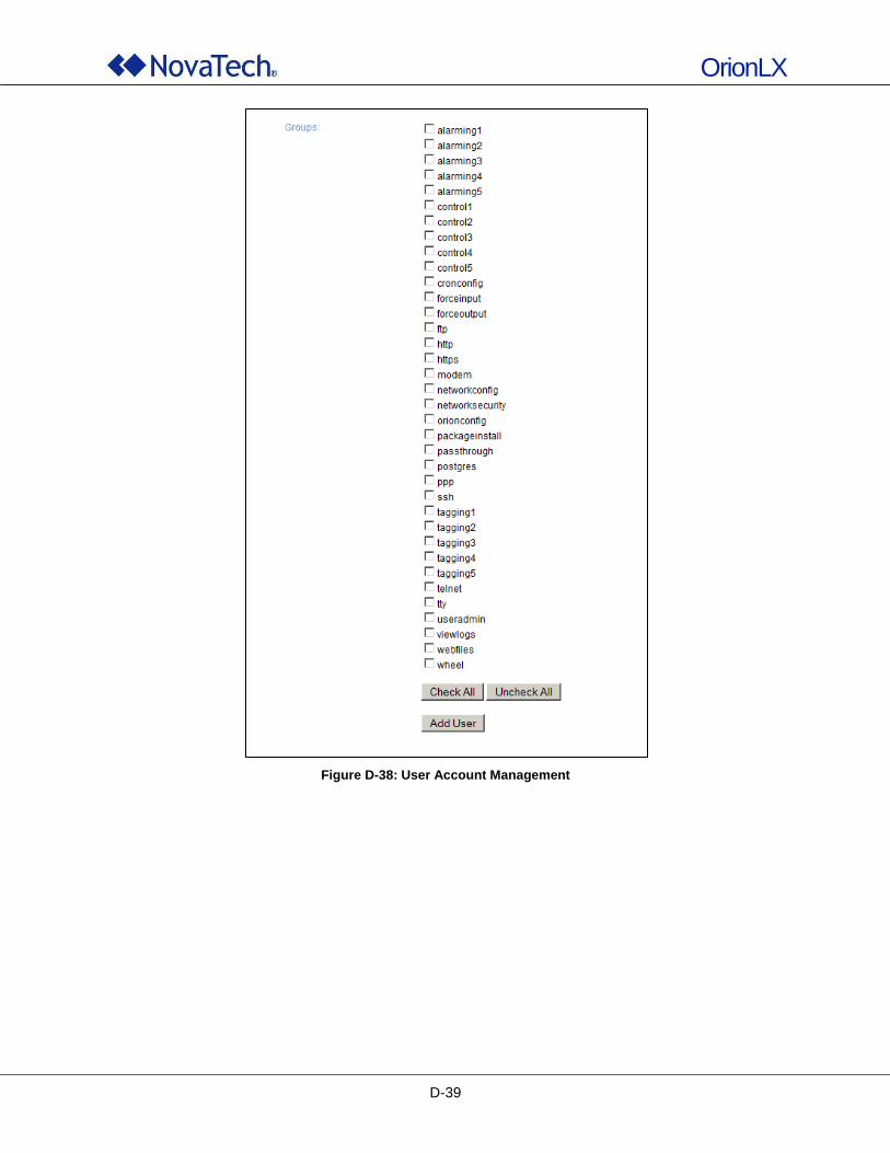
OrionLX
D-39
Figure D-38: User Account Management
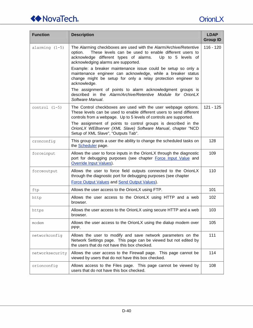
OrionLX
D-40
Function Description LDAP
Group ID
alarming (1-5) The Alarming checkboxes are used with the Alarm/Archive/Retentive
option. These levels can be used to enable different users to
acknowledge different types of alarms. Up to 5 levels of
acknowledging alarms are supported.
Example: a breaker maintenance issue could be setup so only a
maintenance engineer can acknowledge, while a breaker status
change might be setup for only a relay protection engineer to
acknowledge.
The assignment of points to alarm acknowledgment groups is
described in the Alarm/Archive/Retentive Module for OrionLX
Software Manual.
116 - 120
control (1-5) The Control checkboxes are used with the user webpage options.
These levels can be used to enable different users to send different
controls from a webpage. Up to 5 levels of controls are supported.
The assignment of points to control groups is described in the
OrionLX WEBserver (XML Slave) Software Manual, chapter "NCD
Setup of XML Slave", "Outputs Tab".
121 - 125
cronconfig This group grants a user the ability to change the scheduled tasks on the Scheduler page.
128
forceinput Allows the user to force inputs in the OrionLX through the diagnostic
port for debugging purposes (see chapter Force Input Value and
Override Input Values).
109
forceoutput Allows the user to force field outputs connected to the OrionLX
through the diagnostic port for debugging purposes (see chapter
Force Output Values and Send Output Values).
110
ftp Allows the user access to the OrionLX using FTP. 101
http Allows the user access to the OrionLX using HTTP and a web
browser.
102
https Allows the user access to the OrionLX using secure HTTP and a web
browser.
103
modem Allows the user access to the OrionLX using the dialup modem over
PPP.
105
networkconfig Allows the user to modify and save network parameters on the
Network Settings page. This page can be viewed but not edited by
the users that do not have this box checked.
111
networksecurity Allows the user access to the Firewall page. This page cannot be
viewed by users that do not have this box checked.
114
orionconfig Allows access to the Files page. This page cannot be viewed by
users that do not have this box checked.
108
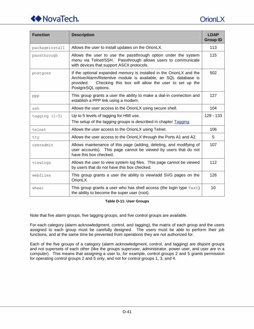
OrionLX
D-41
Function Description LDAP
Group ID
packageinstall Allows the user to install updates on the OrionLX. 113
passthrough Allows the user to use the passthrough option under the system
menu via Telnet/SSH. Passthrough allows users to communicate
with devices that support ASCII protocols.
115
postgres If the optional expanded memory is installed in the OrionLX and the
Archive/Alarm/Retentive module is available, an SQL database is
provided. Checking this box will allow the user to set up the
PostgreSQL options.
502
ppp This group grants a user the ability to make a dial-in connection and
establish a PPP link using a modem.
127
ssh Allows the user access to the OrionLX using secure shell. 104
tagging (1-5) Up to 5 levels of tagging for HMI use.
The setup of the tagging groups is described in chapter Tagging.
129 - 133
telnet Allows the user access to the OrionLX using Telnet. 106
tty Allows the user access to the OrionLX through the Ports A1 and A2. 5
useradmin Allows maintenance of this page (adding, deleting, and modifying of
user accounts). This page cannot be viewed by users that do not
have this box checked.
107
viewlogs Allows the user to view system log files. This page cannot be viewed
by users that do not have this box checked.
112
webfiles This group grants a user the ability to view/add SVG pages on the
OrionLX.
126
wheel This group grants a user who has shell access (the login type Text)
the ability to become the super user (root).
10
Table D-11: User Groups
Note that five alarm groups, five tagging groups, and five control groups are available. For each category (alarm acknowledgment, control, and tagging), the matrix of each group and the users assigned to each group must be carefully designed. The users must be able to perform their job functions, and at the same time be prevented from operations they are not authorized for. Each of the five groups of a category (alarm acknowledgment, control, and tagging) are disjoint groups and not supersets of each other (like the groups superuser, administrator, power user, and user are in a computer). This means that assigning a user to, for example, control groups 2 and 5 grants permission for operating control groups 2 and 5 only, and not for control groups 1, 3, and 4.
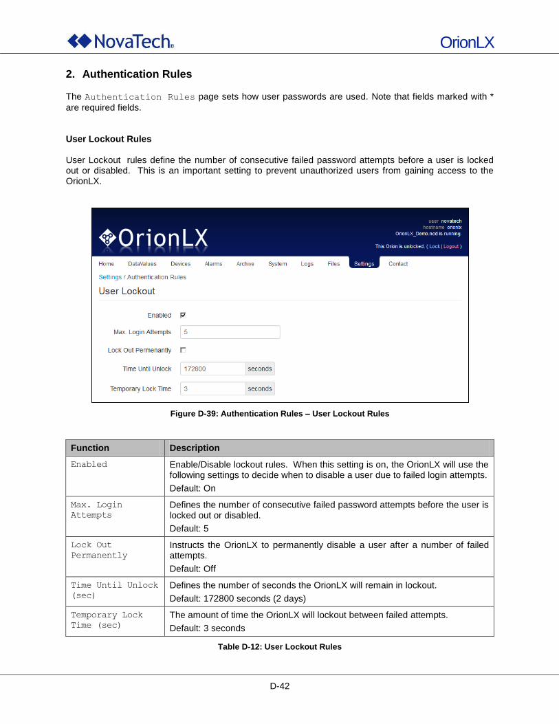
OrionLX
D-42
2. Authentication Rules
The Authentication Rules page sets how user passwords are used. Note that fields marked with *
are required fields. User Lockout Rules User Lockout rules define the number of consecutive failed password attempts before a user is locked out or disabled. This is an important setting to prevent unauthorized users from gaining access to the OrionLX.
Figure D-39: Authentication Rules – User Lockout Rules
Function Description
Enabled Enable/Disable lockout rules. When this setting is on, the OrionLX will use the following settings to decide when to disable a user due to failed login attempts.
Default: On
Max. Login
Attempts
Defines the number of consecutive failed password attempts before the user is locked out or disabled.
Default: 5
Lock Out
Permanently
Instructs the OrionLX to permanently disable a user after a number of failed attempts.
Default: Off
Time Until Unlock
(sec)
Defines the number of seconds the OrionLX will remain in lockout.
Default: 172800 seconds (2 days)
Temporary Lock
Time (sec)
The amount of time the OrionLX will lockout between failed attempts.
Default: 3 seconds
Table D-12: User Lockout Rules
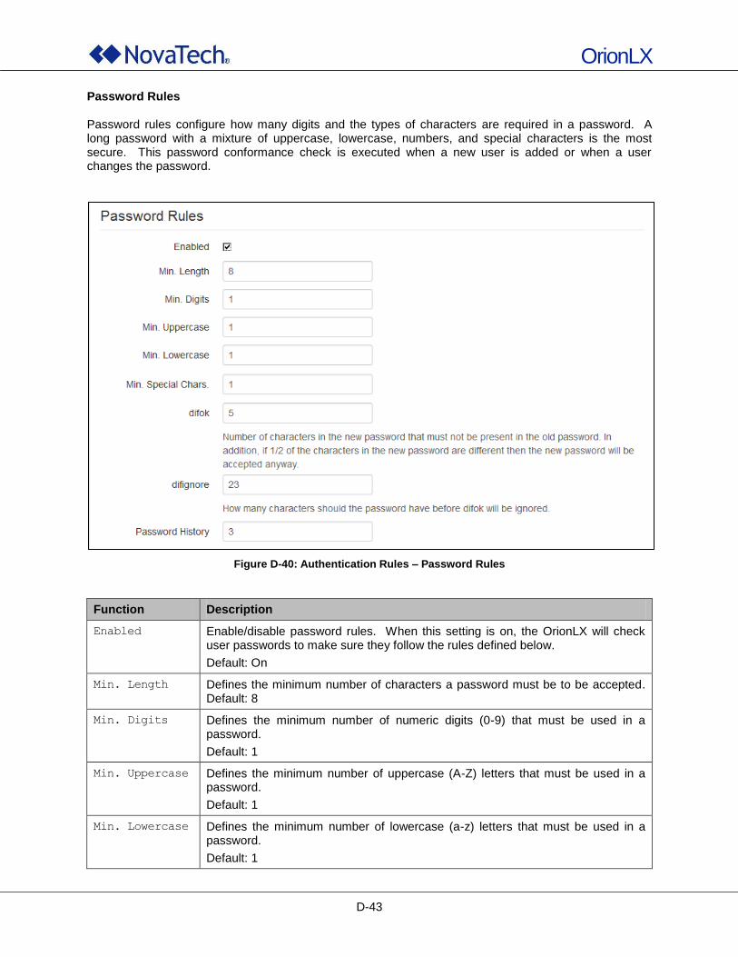
OrionLX
D-43
Password Rules Password rules configure how many digits and the types of characters are required in a password. A long password with a mixture of uppercase, lowercase, numbers, and special characters is the most secure. This password conformance check is executed when a new user is added or when a user changes the password.
Figure D-40: Authentication Rules – Password Rules
Function Description
Enabled Enable/disable password rules. When this setting is on, the OrionLX will check user passwords to make sure they follow the rules defined below.
Default: On
Min. Length Defines the minimum number of characters a password must be to be accepted. Default: 8
Min. Digits Defines the minimum number of numeric digits (0-9) that must be used in a password.
Default: 1
Min. Uppercase Defines the minimum number of uppercase (A-Z) letters that must be used in a password.
Default: 1
Min. Lowercase Defines the minimum number of lowercase (a-z) letters that must be used in a password.
Default: 1
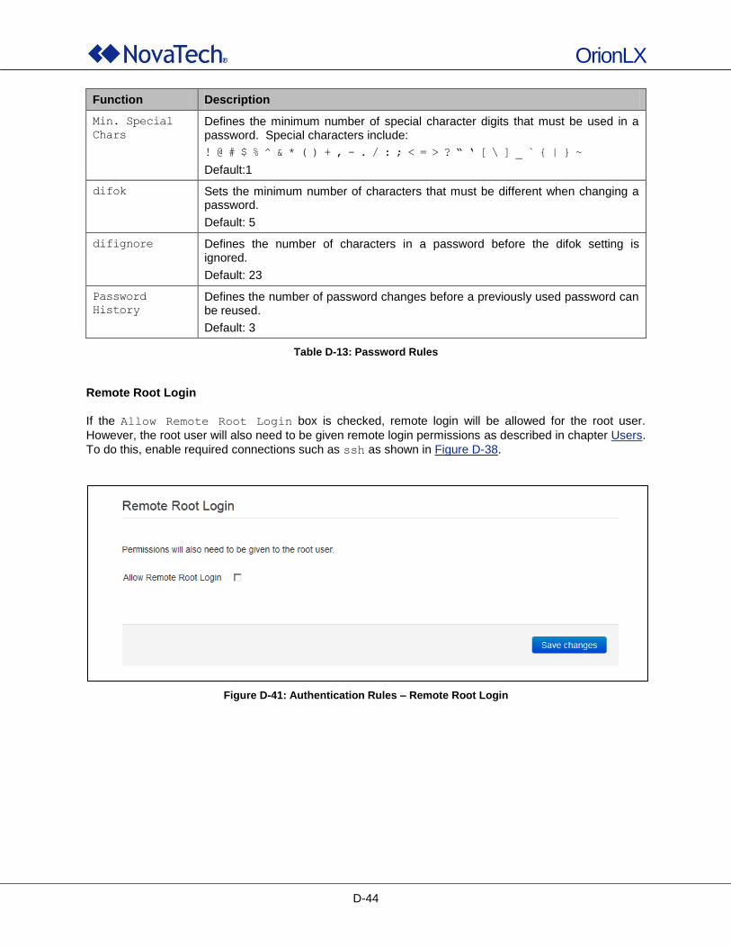
OrionLX
D-44
Function Description
Min. Special
Chars
Defines the minimum number of special character digits that must be used in a password. Special characters include:
! @ # $ % ̂ & * ( ) + , - . / : ; < = > ? “ ‘ [ \ ] _ ̀ { | } ~
Default:1
difok Sets the minimum number of characters that must be different when changing a password.
Default: 5
difignore Defines the number of characters in a password before the difok setting is ignored.
Default: 23
Password
History
Defines the number of password changes before a previously used password can be reused.
Default: 3
Table D-13: Password Rules
Remote Root Login
If the Allow Remote Root Login box is checked, remote login will be allowed for the root user.
However, the root user will also need to be given remote login permissions as described in chapter Users.
To do this, enable required connections such as ssh as shown in Figure D-38.
Figure D-41: Authentication Rules – Remote Root Login
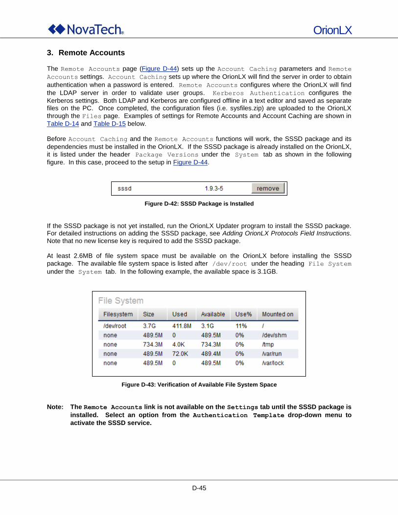
OrionLX
D-45
3. Remote Accounts
The Remote Accounts page (Figure D-44) sets up the Account Caching parameters and Remote
Accounts settings. Account Caching sets up where the OrionLX will find the server in order to obtain
authentication when a password is entered. Remote Accounts configures where the OrionLX will find
the LDAP server in order to validate user groups. Kerberos Authentication configures the
Kerberos settings. Both LDAP and Kerberos are configured offline in a text editor and saved as separate files on the PC. Once completed, the configuration files (i.e. sysfiles.zip) are uploaded to the OrionLX
through the Files page. Examples of settings for Remote Accounts and Account Caching are shown in
Table D-14 and Table D-15 below.
Before Account Caching and the Remote Accounts functions will work, the SSSD package and its
dependencies must be installed in the OrionLX. If the SSSD package is already installed on the OrionLX,
it is listed under the header Package Versions under the System tab as shown in the following
figure. In this case, proceed to the setup in Figure D-44.
Figure D-42: SSSD Package is Installed
If the SSSD package is not yet installed, run the OrionLX Updater program to install the SSSD package. For detailed instructions on adding the SSSD package, see Adding OrionLX Protocols Field Instructions. Note that no new license key is required to add the SSSD package. At least 2.6MB of file system space must be available on the OrionLX before installing the SSSD
package. The available file system space is listed after /dev/root under the heading File System
under the System tab. In the following example, the available space is 3.1GB.
Figure D-43: Verification of Available File System Space
Note: The Remote Accounts link is not available on the Settings tab until the SSSD package is
installed. Select an option from the Authentication Template drop-down menu to
activate the SSSD service.
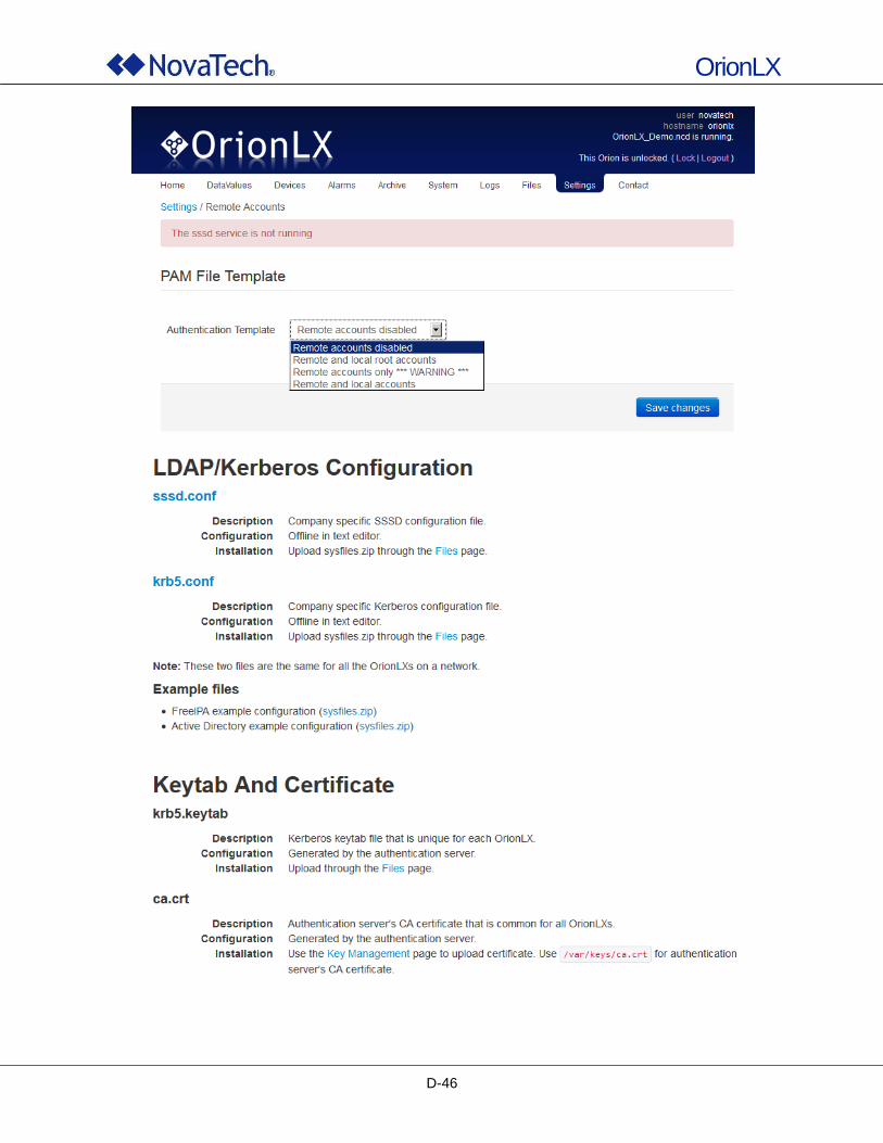
OrionLX
D-46
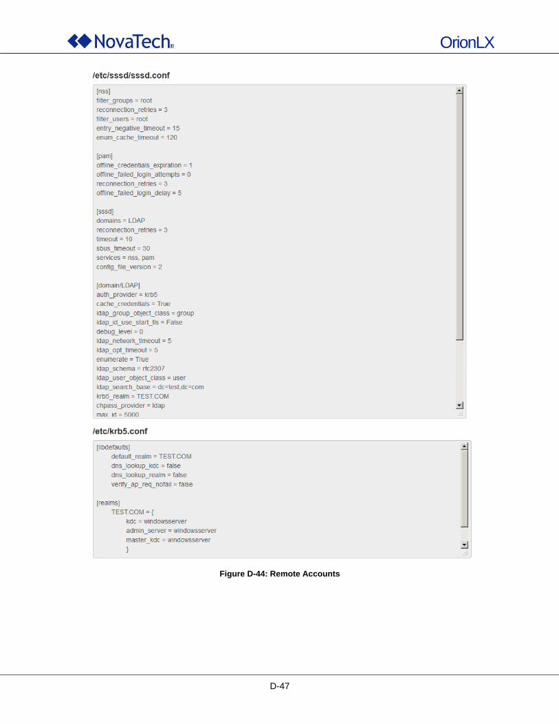
OrionLX
D-47
Figure D-44: Remote Accounts
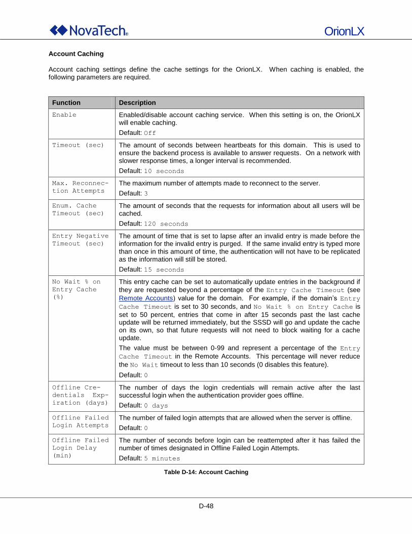
OrionLX
D-48
Account Caching Account caching settings define the cache settings for the OrionLX. When caching is enabled, the following parameters are required.
Function Description
Enable Enabled/disable account caching service. When this setting is on, the OrionLX will enable caching.
Default: Off
Timeout (sec) The amount of seconds between heartbeats for this domain. This is used to ensure the backend process is available to answer requests. On a network with slower response times, a longer interval is recommended.
Default: 10 seconds
Max. Reconnec-
tion Attempts
The maximum number of attempts made to reconnect to the server.
Default: 3
Enum. Cache
Timeout (sec)
The amount of seconds that the requests for information about all users will be cached.
Default: 120 seconds
Entry Negative
Timeout (sec)
The amount of time that is set to lapse after an invalid entry is made before the information for the invalid entry is purged. If the same invalid entry is typed more than once in this amount of time, the authentication will not have to be replicated as the information will still be stored.
Default: 15 seconds
No Wait % on
Entry Cache
(%)
This entry cache can be set to automatically update entries in the background if
they are requested beyond a percentage of the Entry Cache Timeout (see
Remote Accounts) value for the domain. For example, if the domain‟s Entry
Cache Timeout is set to 30 seconds, and No Wait % on Entry Cache is
set to 50 percent, entries that come in after 15 seconds past the last cache update will be returned immediately, but the SSSD will go and update the cache on its own, so that future requests will not need to block waiting for a cache update.
The value must be between 0-99 and represent a percentage of the Entry
Cache Timeout in the Remote Accounts. This percentage will never reduce
the No Wait timeout to less than 10 seconds (0 disables this feature).
Default: 0
Offline Cre-
dentials Exp-
iration (days)
The number of days the login credentials will remain active after the last successful login when the authentication provider goes offline.
Default: 0 days
Offline Failed
Login Attempts
The number of failed login attempts that are allowed when the server is offline.
Default: 0
Offline Failed
Login Delay
(min)
The number of seconds before login can be reattempted after it has failed the number of times designated in Offline Failed Login Attempts.
Default: 5 minutes
Table D-14: Account Caching
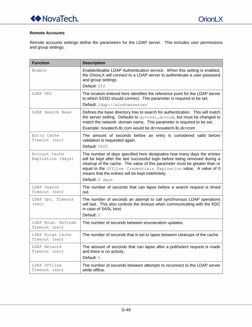
OrionLX
D-49
Remote Accounts Remote accounts settings define the parameters for the LDAP server. This includes user permissions and group settings.
Function Description
Enable Enable/disable LDAP Authentication service. When this setting is enabled, the OrionLX will connect to a LDAP server to authenticate a user password and group settings.
Default: Off
LDAP URI The location entered here identifies the reference point for the LDAP server to which SSSD should connect. This parameter is required to be set.
Default: ldap://windowsserver
LDAP Search Base Defines the base directory tree to search for authentication. This will match
the server setting. Defaults to dc=test,dc=com, but must be changed to
match the network domain name. This parameter is required to be set.
Example: novatech-llc.com would be dc=novatech-llc,dc=com
Entry Cache
Timeout (sec)
The amount of seconds before an entry is considered valid before validation is requested again.
Default: 5400
Account Cache
Expiration (days)
The number of days specified here designates how many days the entries will be kept after the last successful login before being removed during a cleanup of the cache. The value of this parameter must be greater than or
equal to the Offline Credentials Expiration value. A value of 0
means that the entries will be kept indefinitely.
Default: 0 days
LDAP Search
Timeout (sec)
The number of seconds that can lapse before a search request is timed out.
LDAP Opt. Timeout
(sec)
The number of seconds an attempt to call synchronous LDAP operations will last. This also controls the timeout when communicating with the KDC in case of SASL bind.
Default: 5
LDAP Enum. Refresh
Timeout (sec)
The number of seconds between enumeration updates.
LDAP Purge Cache
Timeout (sec)
The number of seconds that is set to lapse between cleanups of the cache.
LDAP Network
Timeout (sec)
The amount of seconds that can lapse after a poll/select request is made and there is no activity.
Default: 5
LDAP Offline
Timeout (sec)
The number of seconds between attempts to reconnect to the LDAP server while offline.
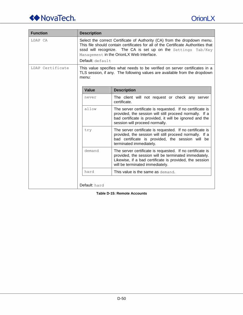
OrionLX
D-50
Function Description
LDAP CA Select the correct Certificate of Authority (CA) from the dropdown menu. This file should contain certificates for all of the Certificate Authorities that
sssd will recognize. The CA is set up on the Settings Tab/Key
Management in the OrionLX Web Interface.
Default: default
LDAP Certificate This value specifies what needs to be verified on server certificates in a TLS session, if any. The following values are available from the dropdown menu:
Value Description
never The client will not request or check any server certificate.
allow The server certificate is requested. If no certificate is provided, the session will still proceed normally. If a bad certificate is provided, it will be ignored and the session will proceed normally.
try The server certificate is requested. If no certificate is provided, the session will still proceed normally. If a bad certificate is provided, the session will be terminated immediately.
demand The server certificate is requested. If no certificate is provided, the session will be terminated immediately. Likewise, if a bad certificate is provided, the session will be terminated immediately.
hard This value is the same as demand.
Default: hard
Table D-15: Remote Accounts
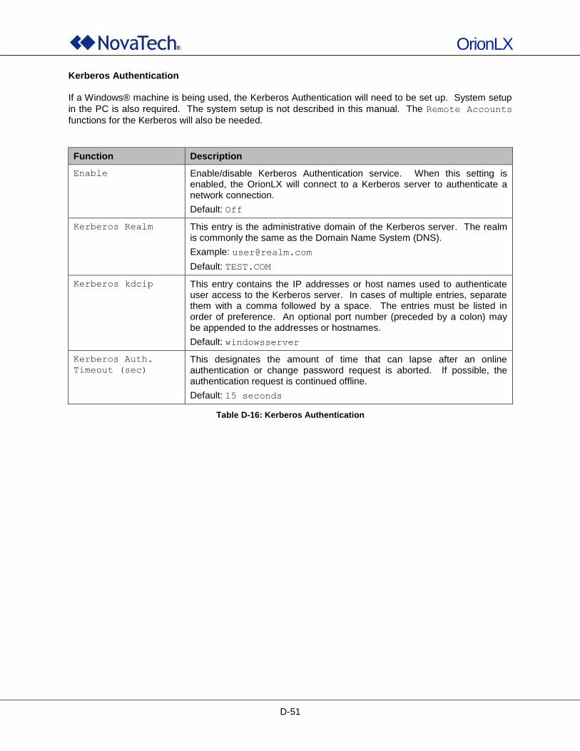
OrionLX
D-51
Kerberos Authentication If a Windows® machine is being used, the Kerberos Authentication will need to be set up. System setup
in the PC is also required. The system setup is not described in this manual. The Remote Accounts
functions for the Kerberos will also be needed.
Function Description
Enable Enable/disable Kerberos Authentication service. When this setting is enabled, the OrionLX will connect to a Kerberos server to authenticate a network connection.
Default: Off
Kerberos Realm This entry is the administrative domain of the Kerberos server. The realm is commonly the same as the Domain Name System (DNS).
Example: [email protected]
Default: TEST.COM
Kerberos kdcip This entry contains the IP addresses or host names used to authenticate user access to the Kerberos server. In cases of multiple entries, separate them with a comma followed by a space. The entries must be listed in order of preference. An optional port number (preceded by a colon) may be appended to the addresses or hostnames.
Default: windowsserver
Kerberos Auth.
Timeout (sec)
This designates the amount of time that can lapse after an online authentication or change password request is aborted. If possible, the authentication request is continued offline.
Default: 15 seconds
Table D-16: Kerberos Authentication
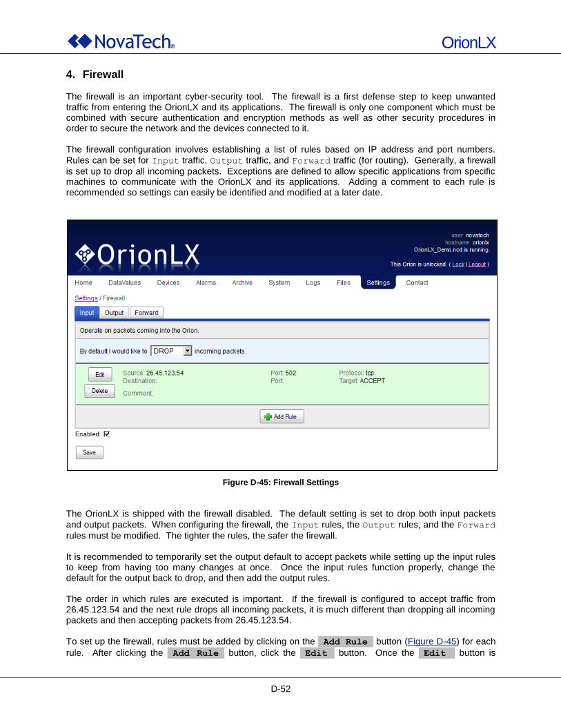
OrionLX
D-52
4. Firewall The firewall is an important cyber-security tool. The firewall is a first defense step to keep unwanted traffic from entering the OrionLX and its applications. The firewall is only one component which must be combined with secure authentication and encryption methods as well as other security procedures in order to secure the network and the devices connected to it. The firewall configuration involves establishing a list of rules based on IP address and port numbers.
Rules can be set for Input traffic, Output traffic, and Forward traffic (for routing). Generally, a firewall
is set up to drop all incoming packets. Exceptions are defined to allow specific applications from specific machines to communicate with the OrionLX and its applications. Adding a comment to each rule is recommended so settings can easily be identified and modified at a later date.
Figure D-45: Firewall Settings
The OrionLX is shipped with the firewall disabled. The default setting is set to drop both input packets
and output packets. When configuring the firewall, the Input rules, the Output rules, and the Forward
rules must be modified. The tighter the rules, the safer the firewall. It is recommended to temporarily set the output default to accept packets while setting up the input rules to keep from having too many changes at once. Once the input rules function properly, change the default for the output back to drop, and then add the output rules. The order in which rules are executed is important. If the firewall is configured to accept traffic from 26.45.123.54 and the next rule drops all incoming packets, it is much different than dropping all incoming packets and then accepting packets from 26.45.123.54. To set up the firewall, rules must be added by clicking on the Add Rule button (Figure D-45) for each
rule. After clicking the Add Rule button, click the Edit button. Once the Edit button is
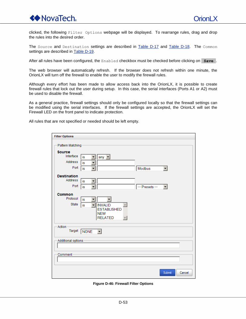
OrionLX
D-53
clicked, the following Filter Options webpage will be displayed. To rearrange rules, drag and drop
the rules into the desired order.
The Source and Destination settings are described in Table D-17 and Table D-18. The Common
settings are described in Table D-19. After all rules have been configured, the Enabled checkbox must be checked before clicking on Save .
The web browser will automatically refresh. If the browser does not refresh within one minute, the OrionLX will turn off the firewall to enable the user to modify the firewall rules. Although every effort has been made to allow access back into the OrionLX, it is possible to create firewall rules that lock out the user during setup. In this case, the serial interfaces (Ports A1 or A2) must be used to disable the firewall. As a general practice, firewall settings should only be configured locally so that the firewall settings can be modified using the serial interfaces. If the firewall settings are accepted, the OrionLX will set the Firewall LED on the front panel to indicate protection. All rules that are not specified or needed should be left empty.
Figure D-46: Firewall Filter Options
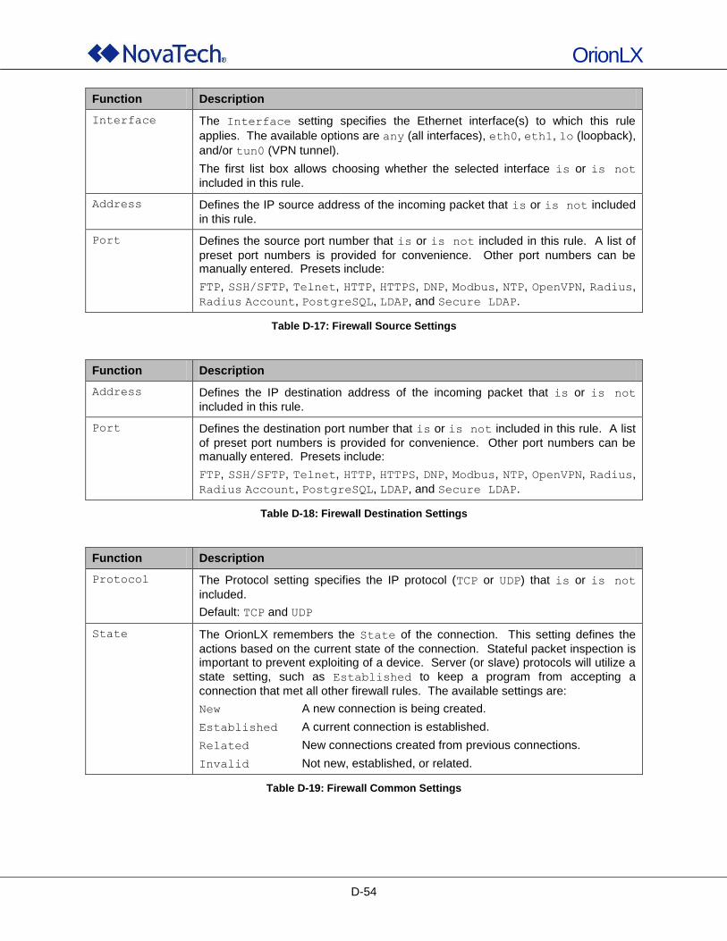
OrionLX
D-54
Function Description
Interface The Interface setting specifies the Ethernet interface(s) to which this rule
applies. The available options are any (all interfaces), eth0, eth1, lo (loopback),
and/or tun0 (VPN tunnel).
The first list box allows choosing whether the selected interface is or is not
included in this rule.
Address Defines the IP source address of the incoming packet that is or is not included
in this rule.
Port Defines the source port number that is or is not included in this rule. A list of
preset port numbers is provided for convenience. Other port numbers can be manually entered. Presets include:
FTP, SSH/SFTP, Telnet, HTTP, HTTPS, DNP, Modbus, NTP, OpenVPN, Radius,
Radius Account, PostgreSQL, LDAP, and Secure LDAP.
Table D-17: Firewall Source Settings
Function Description
Address Defines the IP destination address of the incoming packet that is or is not
included in this rule.
Port Defines the destination port number that is or is not included in this rule. A list
of preset port numbers is provided for convenience. Other port numbers can be manually entered. Presets include:
FTP, SSH/SFTP, Telnet, HTTP, HTTPS, DNP, Modbus, NTP, OpenVPN, Radius,
Radius Account, PostgreSQL, LDAP, and Secure LDAP.
Table D-18: Firewall Destination Settings
Function Description
Protocol The Protocol setting specifies the IP protocol (TCP or UDP) that is or is not
included.
Default: TCP and UDP
State The OrionLX remembers the State of the connection. This setting defines the
actions based on the current state of the connection. Stateful packet inspection is important to prevent exploiting of a device. Server (or slave) protocols will utilize a
state setting, such as Established to keep a program from accepting a
connection that met all other firewall rules. The available settings are:
New A new connection is being created.
Established A current connection is established.
Related New connections created from previous connections.
Invalid Not new, established, or related.
Table D-19: Firewall Common Settings
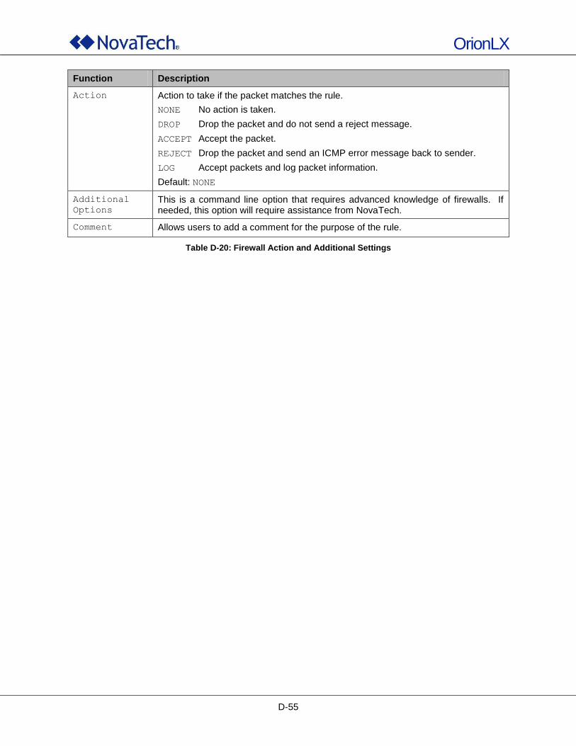
OrionLX
D-55
Function Description
Action Action to take if the packet matches the rule.
NONE No action is taken.
DROP Drop the packet and do not send a reject message.
ACCEPT Accept the packet.
REJECT Drop the packet and send an ICMP error message back to sender.
LOG Accept packets and log packet information.
Default: NONE
Additional
Options
This is a command line option that requires advanced knowledge of firewalls. If needed, this option will require assistance from NovaTech.
Comment Allows users to add a comment for the purpose of the rule.
Table D-20: Firewall Action and Additional Settings
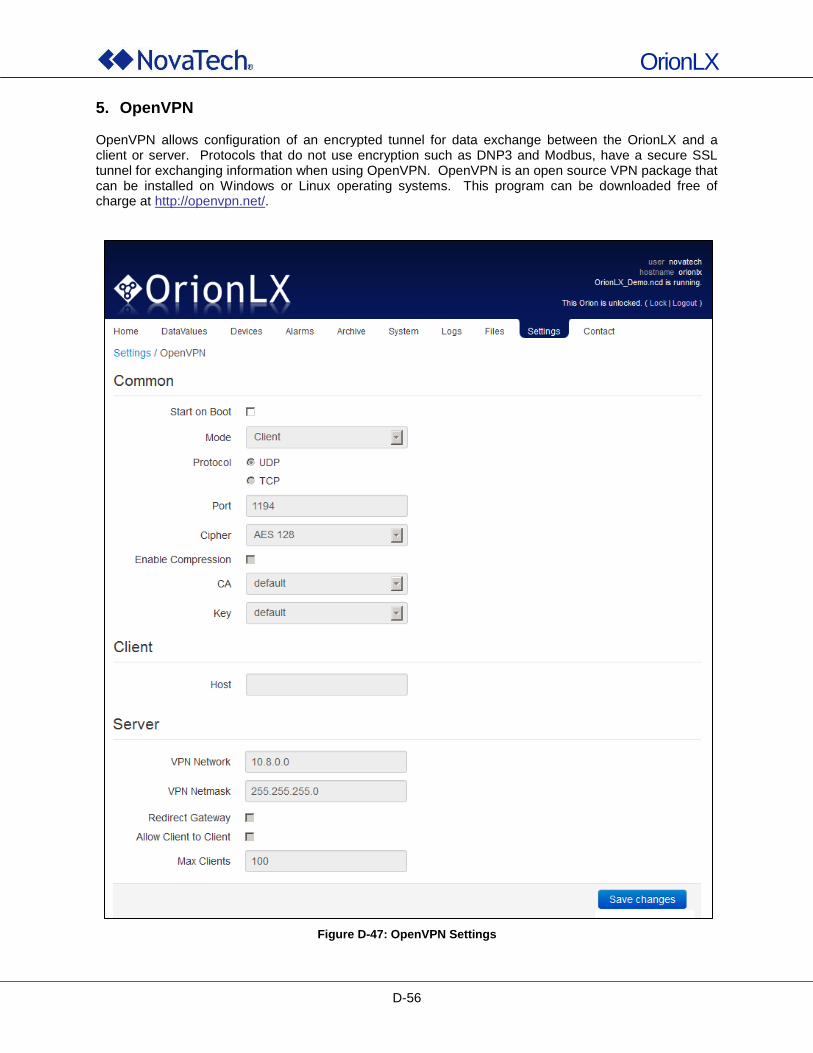
OrionLX
D-56
5. OpenVPN OpenVPN allows configuration of an encrypted tunnel for data exchange between the OrionLX and a client or server. Protocols that do not use encryption such as DNP3 and Modbus, have a secure SSL tunnel for exchanging information when using OpenVPN. OpenVPN is an open source VPN package that can be installed on Windows or Linux operating systems. This program can be downloaded free of charge at http://openvpn.net/.
Figure D-47: OpenVPN Settings
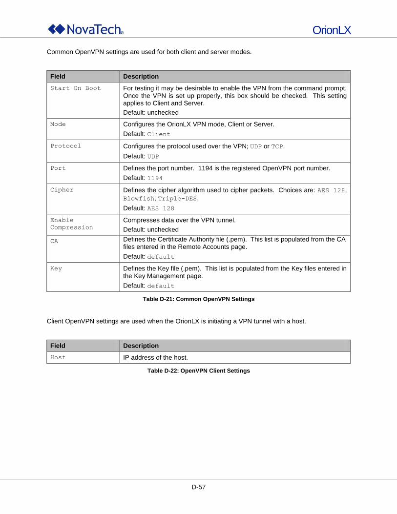
OrionLX
D-57
Common OpenVPN settings are used for both client and server modes.
Field Description
Start On Boot For testing it may be desirable to enable the VPN from the command prompt. Once the VPN is set up properly, this box should be checked. This setting applies to Client and Server.
Default: unchecked
Mode Configures the OrionLX VPN mode, Client or Server.
Default: Client
Protocol Configures the protocol used over the VPN; UDP or TCP.
Default: UDP
Port Defines the port number. 1194 is the registered OpenVPN port number.
Default: 1194
Cipher Defines the cipher algorithm used to cipher packets. Choices are: AES 128,
Blowfish, Triple-DES.
Default: AES 128
Enable
Compression
Compresses data over the VPN tunnel.
Default: unchecked
CA Defines the Certificate Authority file (.pem). This list is populated from the CA files entered in the Remote Accounts page.
Default: default
Key Defines the Key file (.pem). This list is populated from the Key files entered in the Key Management page.
Default: default
Table D-21: Common OpenVPN Settings
Client OpenVPN settings are used when the OrionLX is initiating a VPN tunnel with a host.
Field Description
Host IP address of the host.
Table D-22: OpenVPN Client Settings
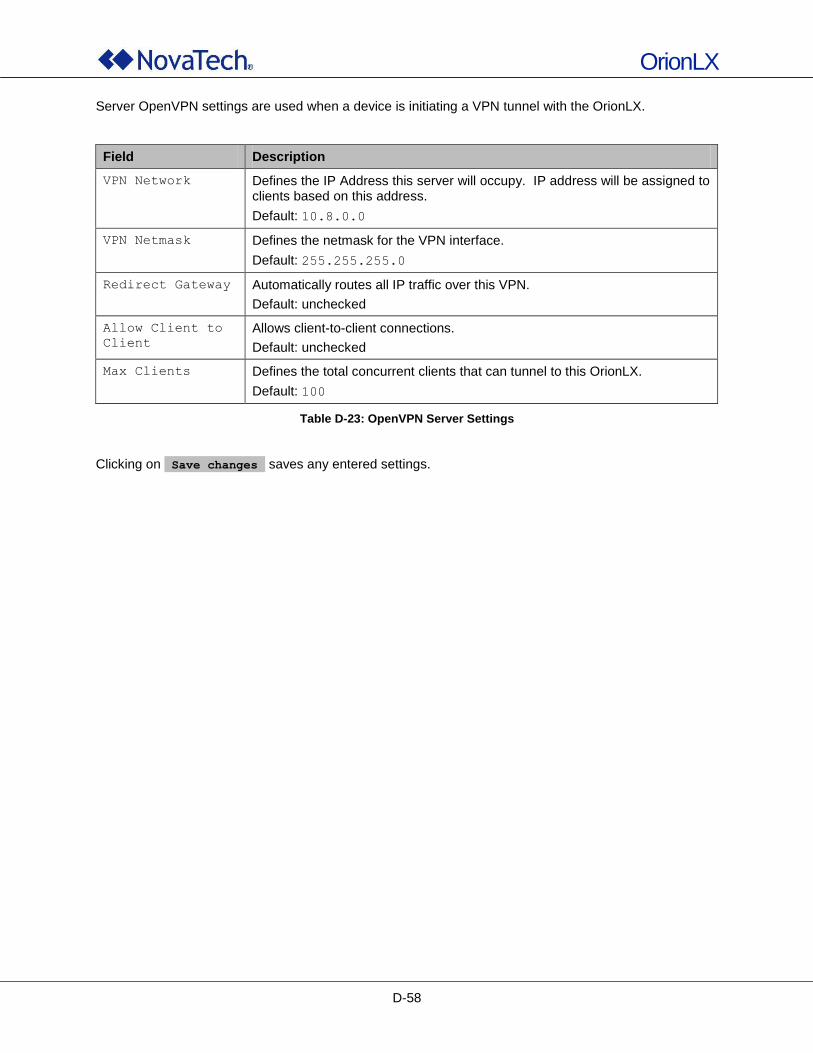
OrionLX
D-58
Server OpenVPN settings are used when a device is initiating a VPN tunnel with the OrionLX.
Field Description
VPN Network Defines the IP Address this server will occupy. IP address will be assigned to clients based on this address.
Default: 10.8.0.0
VPN Netmask Defines the netmask for the VPN interface.
Default: 255.255.255.0
Redirect Gateway Automatically routes all IP traffic over this VPN.
Default: unchecked
Allow Client to
Client
Allows client-to-client connections.
Default: unchecked
Max Clients Defines the total concurrent clients that can tunnel to this OrionLX.
Default: 100
Table D-23: OpenVPN Server Settings
Clicking on Save changes saves any entered settings.
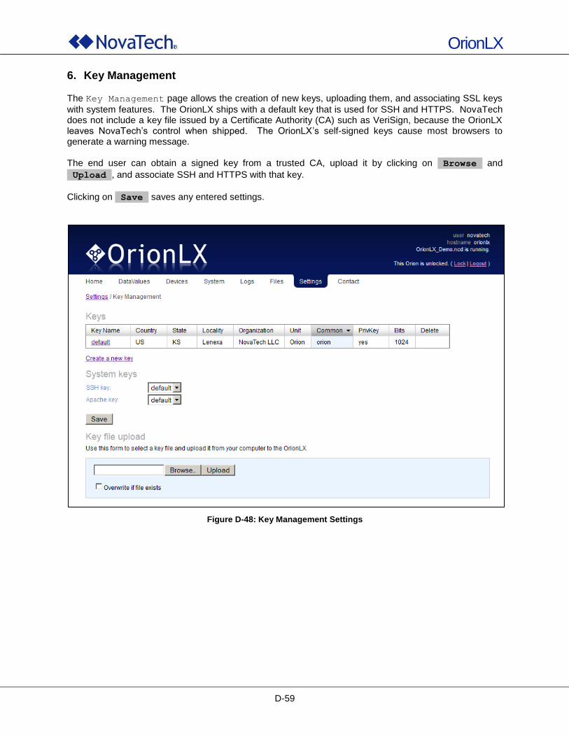
OrionLX
D-59
6. Key Management
The Key Management page allows the creation of new keys, uploading them, and associating SSL keys
with system features. The OrionLX ships with a default key that is used for SSH and HTTPS. NovaTech does not include a key file issued by a Certificate Authority (CA) such as VeriSign, because the OrionLX leaves NovaTech‟s control when shipped. The OrionLX‟s self-signed keys cause most browsers to generate a warning message. The end user can obtain a signed key from a trusted CA, upload it by clicking on Browse and
Upload , and associate SSH and HTTPS with that key.
Clicking on Save saves any entered settings.
Figure D-48: Key Management Settings
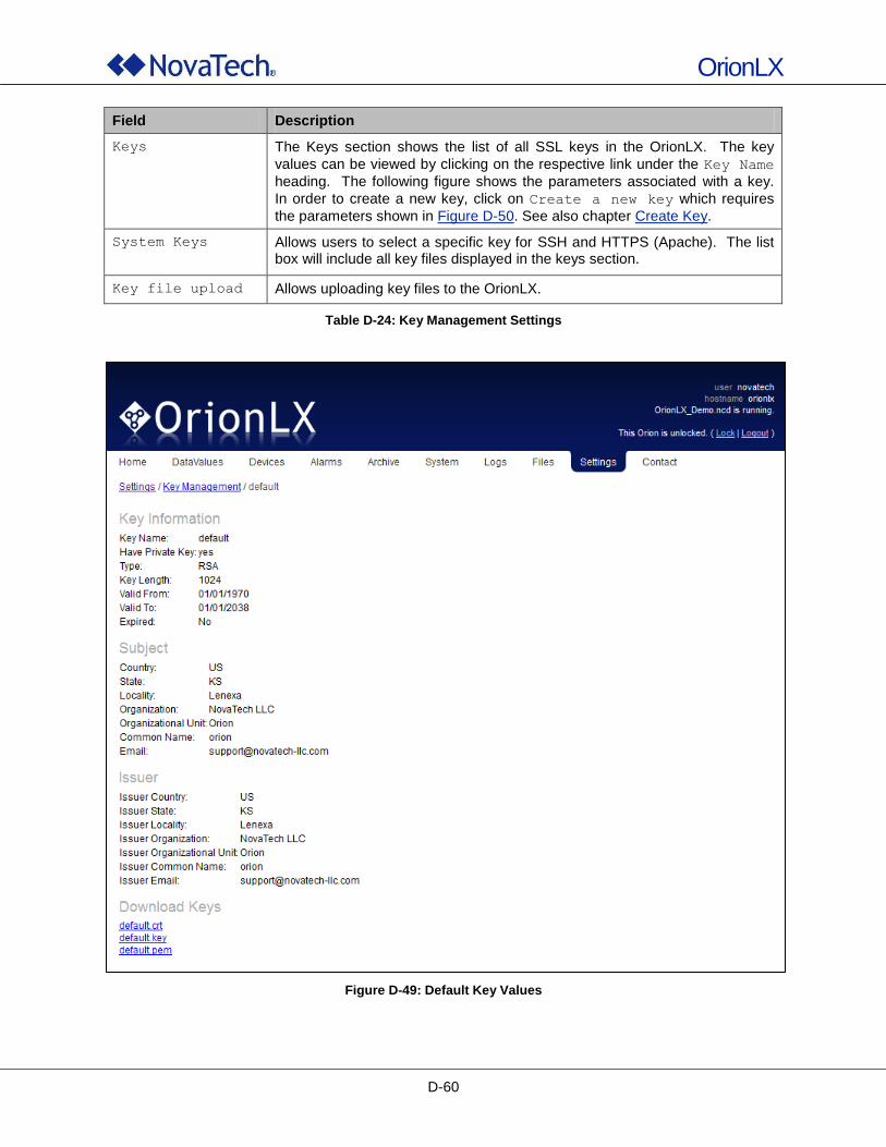
OrionLX
D-60
Field Description
Keys The Keys section shows the list of all SSL keys in the OrionLX. The key
values can be viewed by clicking on the respective link under the Key Name
heading. The following figure shows the parameters associated with a key.
In order to create a new key, click on Create a new key which requires
the parameters shown in Figure D-50. See also chapter Create Key.
System Keys
Allows users to select a specific key for SSH and HTTPS (Apache). The list box will include all key files displayed in the keys section.
Key file upload Allows uploading key files to the OrionLX.
Table D-24: Key Management Settings
Figure D-49: Default Key Values
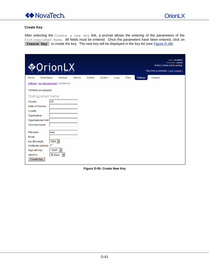
OrionLX
D-61
Create Key
After selecting the Create a new key link, a prompt allows the entering of the parameters of the
Distinguished Name. All fields must be entered. Once the parameters have been entered, click on
Create Key to create the key. The new key will be displayed in the key list (see Figure D-48).
Figure D-50: Create New Key
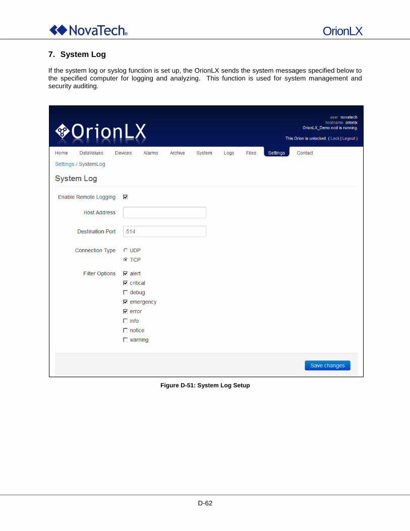
OrionLX
D-62
7. System Log If the system log or syslog function is set up, the OrionLX sends the system messages specified below to the specified computer for logging and analyzing. This function is used for system management and security auditing.
Figure D-51: System Log Setup
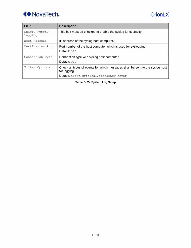
OrionLX
D-63
Field Description
Enable Remote
Logging
This box must be checked to enable the syslog functionality.
Host Address IP address of the syslog host computer.
Destination Port Port number of the host computer which is used for syslogging.
Default: 514
Connection Type Connection type with syslog host computer.
Default: TCP
Filter Options Check all types of events for which messages shall be sent to the syslog host for logging.
Default: alert, critical, emergency, error.
Table D-25: System Log Setup
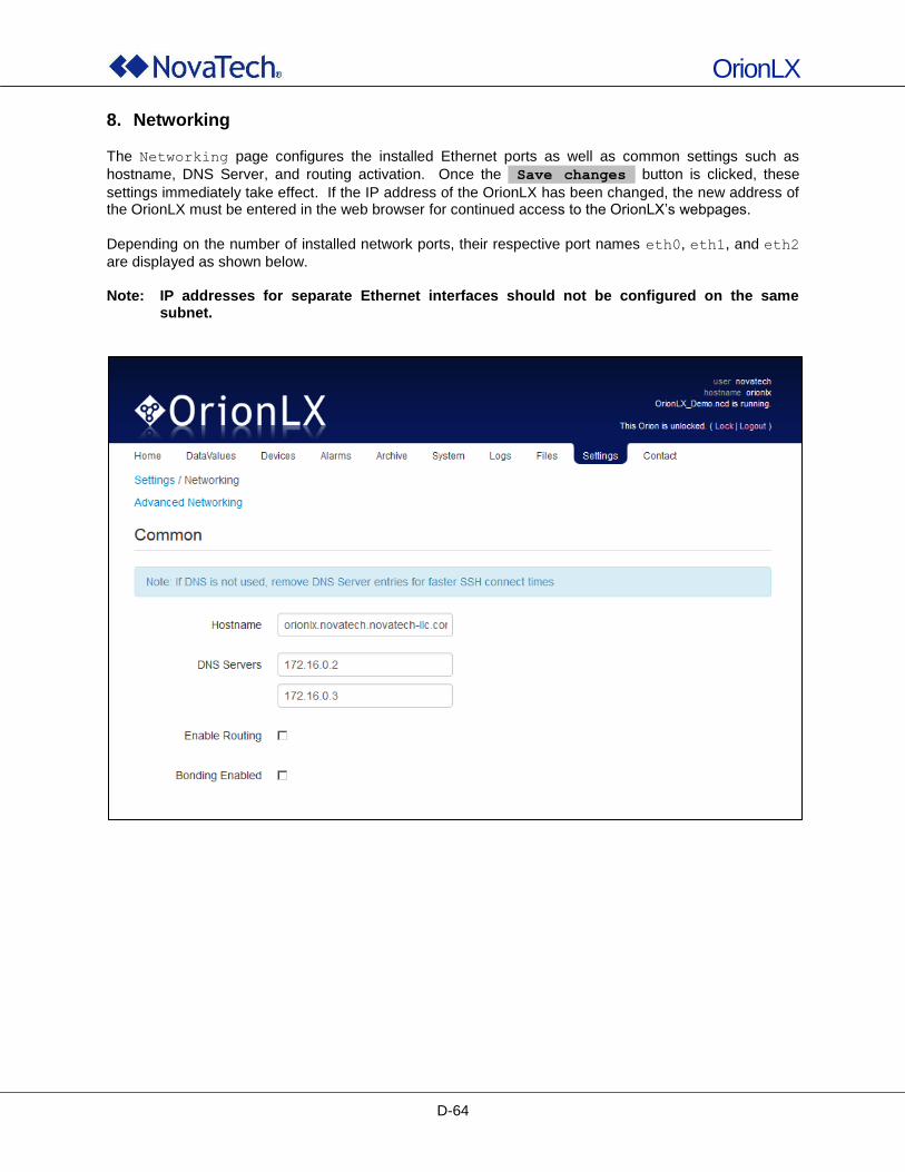
OrionLX
D-64
8. Networking
The Networking page configures the installed Ethernet ports as well as common settings such as
hostname, DNS Server, and routing activation. Once the Save changes button is clicked, these
settings immediately take effect. If the IP address of the OrionLX has been changed, the new address of the OrionLX must be entered in the web browser for continued access to the OrionLX‟s webpages.
Depending on the number of installed network ports, their respective port names eth0, eth1, and eth2
are displayed as shown below. Note: IP addresses for separate Ethernet interfaces should not be configured on the same
subnet.
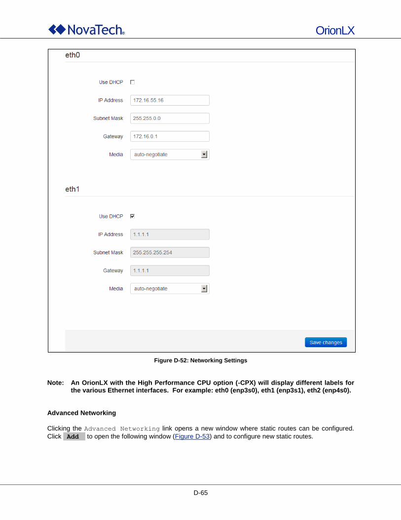
OrionLX
D-65
Figure D-52: Networking Settings
Note: An OrionLX with the High Performance CPU option (-CPX) will display different labels for
the various Ethernet interfaces. For example: eth0 (enp3s0), eth1 (enp3s1), eth2 (enp4s0). Advanced Networking
Clicking the Advanced Networking link opens a new window where static routes can be configured.
Click Add to open the following window (Figure D-53) and to configure new static routes.
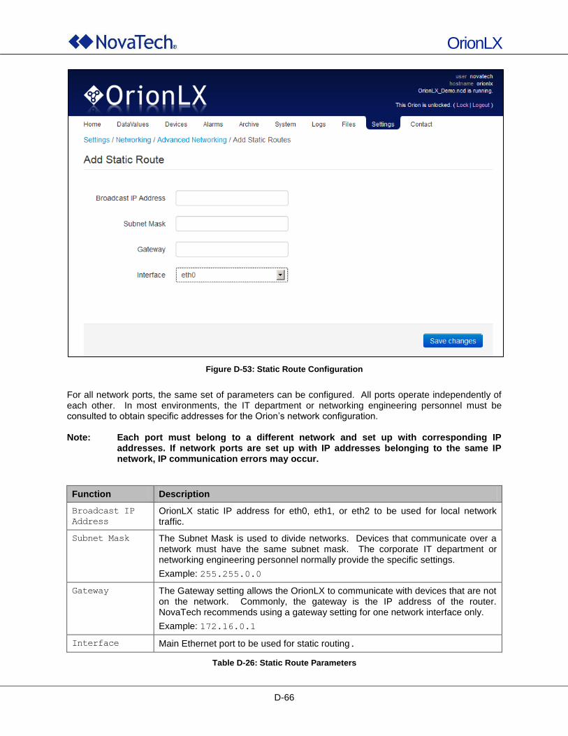
OrionLX
D-66
Figure D-53: Static Route Configuration
For all network ports, the same set of parameters can be configured. All ports operate independently of each other. In most environments, the IT department or networking engineering personnel must be consulted to obtain specific addresses for the Orion‟s network configuration. Note: Each port must belong to a different network and set up with corresponding IP
addresses. If network ports are set up with IP addresses belonging to the same IP network, IP communication errors may occur.
Function Description
Broadcast IP
Address
OrionLX static IP address for eth0, eth1, or eth2 to be used for local network traffic.
Subnet Mask The Subnet Mask is used to divide networks. Devices that communicate over a network must have the same subnet mask. The corporate IT department or networking engineering personnel normally provide the specific settings.
Example: 255.255.0.0
Gateway The Gateway setting allows the OrionLX to communicate with devices that are not on the network. Commonly, the gateway is the IP address of the router. NovaTech recommends using a gateway setting for one network interface only.
Example: 172.16.0.1
Interface Main Ethernet port to be used for static routing.
Table D-26: Static Route Parameters
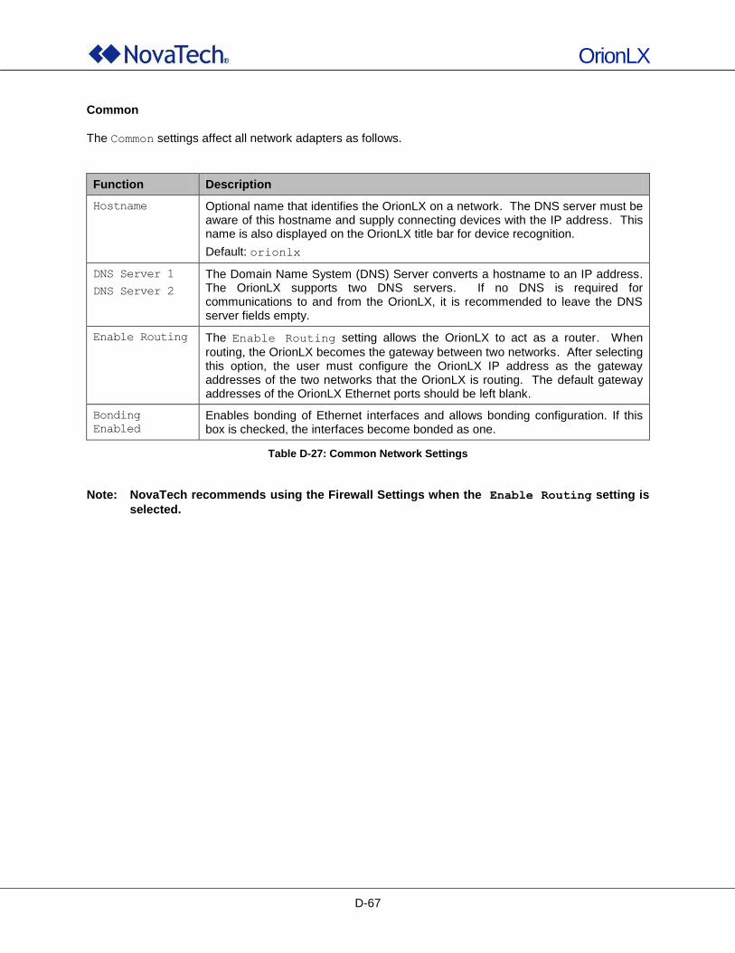
OrionLX
D-67
Common
The Common settings affect all network adapters as follows.
Function Description
Hostname Optional name that identifies the OrionLX on a network. The DNS server must be aware of this hostname and supply connecting devices with the IP address. This name is also displayed on the OrionLX title bar for device recognition.
Default: orionlx
DNS Server 1
DNS Server 2
The Domain Name System (DNS) Server converts a hostname to an IP address. The OrionLX supports two DNS servers. If no DNS is required for communications to and from the OrionLX, it is recommended to leave the DNS server fields empty.
Enable Routing The Enable Routing setting allows the OrionLX to act as a router. When
routing, the OrionLX becomes the gateway between two networks. After selecting this option, the user must configure the OrionLX IP address as the gateway addresses of the two networks that the OrionLX is routing. The default gateway addresses of the OrionLX Ethernet ports should be left blank.
Bonding
Enabled
Enables bonding of Ethernet interfaces and allows bonding configuration. If this box is checked, the interfaces become bonded as one.
Table D-27: Common Network Settings
Note: NovaTech recommends using the Firewall Settings when the Enable Routing setting is
selected.
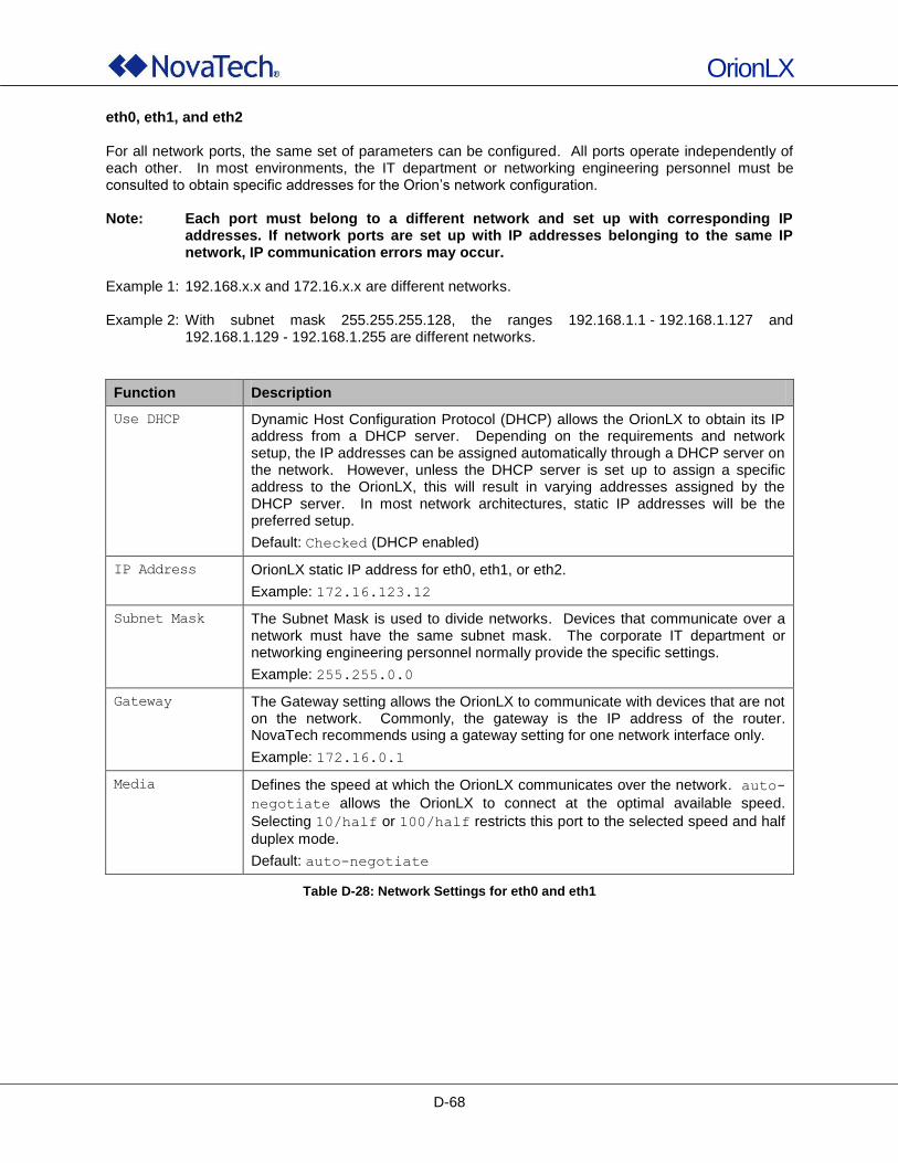
OrionLX
D-68
eth0, eth1, and eth2 For all network ports, the same set of parameters can be configured. All ports operate independently of each other. In most environments, the IT department or networking engineering personnel must be consulted to obtain specific addresses for the Orion‟s network configuration. Note: Each port must belong to a different network and set up with corresponding IP
addresses. If network ports are set up with IP addresses belonging to the same IP network, IP communication errors may occur.
Example 1: 192.168.x.x and 172.16.x.x are different networks. Example 2: With subnet mask 255.255.255.128, the ranges 192.168.1.1 - 192.168.1.127 and
192.168.1.129 - 192.168.1.255 are different networks.
Function Description
Use DHCP Dynamic Host Configuration Protocol (DHCP) allows the OrionLX to obtain its IP address from a DHCP server. Depending on the requirements and network setup, the IP addresses can be assigned automatically through a DHCP server on the network. However, unless the DHCP server is set up to assign a specific address to the OrionLX, this will result in varying addresses assigned by the DHCP server. In most network architectures, static IP addresses will be the preferred setup.
Default: Checked (DHCP enabled)
IP Address OrionLX static IP address for eth0, eth1, or eth2.
Example: 172.16.123.12
Subnet Mask The Subnet Mask is used to divide networks. Devices that communicate over a network must have the same subnet mask. The corporate IT department or networking engineering personnel normally provide the specific settings.
Example: 255.255.0.0
Gateway The Gateway setting allows the OrionLX to communicate with devices that are not on the network. Commonly, the gateway is the IP address of the router. NovaTech recommends using a gateway setting for one network interface only.
Example: 172.16.0.1
Media Defines the speed at which the OrionLX communicates over the network. auto-
negotiate allows the OrionLX to connect at the optimal available speed.
Selecting 10/half or 100/half restricts this port to the selected speed and half
duplex mode.
Default: auto-negotiate
Table D-28: Network Settings for eth0 and eth1
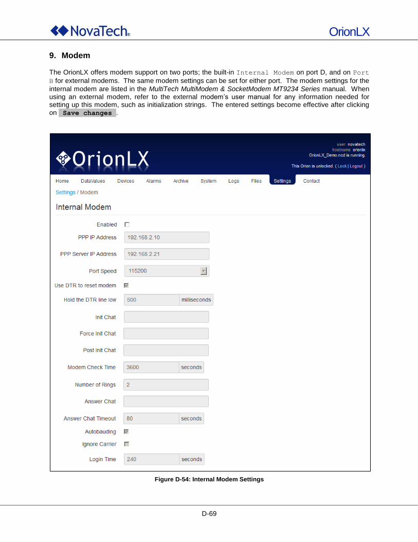
OrionLX
D-69
9. Modem
The OrionLX offers modem support on two ports; the built-in Internal Modem on port D, and on Port
B for external modems. The same modem settings can be set for either port. The modem settings for the
internal modem are listed in the MultiTech MultiModem & SocketModem MT9234 Series manual. When using an external modem, refer to the external modem‟s user manual for any information needed for setting up this modem, such as initialization strings. The entered settings become effective after clicking on Save changes .
Figure D-54: Internal Modem Settings
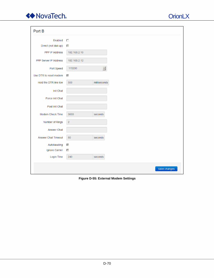
OrionLX
D-70
Figure D-55: External Modem Settings
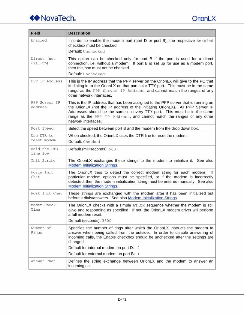
OrionLX
D-71
Field Description
Enabled In order to enable the modem port (port D or port B), the respective Enabled
checkbox must be checked.
Default: Unchecked
Direct (not
dial-up)
This option can be checked only for port B if the port is used for a direct connection, i.e. without a modem. If port B is set up for use as a modem port, then this box must not be checked.
Default: Unchecked
PPP IP Address This is the IP address that the PPP server on the OrionLX will give to the PC that is dialing in to the OrionLX on that particular TTY port. This must be in the same
range as the PPP Server IP Address, and cannot match the ranges of any
other network interfaces.
PPP Server IP
Address
This is the IP address that has been assigned to the PPP server that is running on the OrionLX (not the IP address of the initiating OrionLX). All PPP Server IP Addresses should be the same on every TTY port. This must be in the same
range as the PPP IP Address, and cannot match the ranges of any other
network interfaces.
Port Speed Select the speed between port B and the modem from the drop down box.
Use DTR to
reset modem
When checked, the OrionLX uses the DTR line to reset the modem.
Default: Checked
Hold the DTR
line low
Default (milliseconds): 500
Init String The OrionLX exchanges these strings to the modem to initialize it. See also Modem Initialization Strings.
Force Init
Chat
The OrionLX tries to detect the correct modem string for each modem. If particular modem options must be specified, or if the modem is incorrectly detected, then the modem initialization string must be entered manually. See also Modem Initialization Strings.
Post Init Chat These strings are exchanged with the modem after it has been initialized but before it dials/answers. See also Modem Initialization Strings.
Modem Check
Time
The OrionLX checks with a simple AT…OK sequence whether the modem is still
alive and responding as specified. If not, the OrionLX modem driver will perform a full modem reset.
Default (seconds): 3600
Number of
Rings
Specifies the number of rings after which the OrionLX instructs the modem to answer when being called from the outside. In order to disable answering of incoming calls, the Enable checkbox should be unchecked after the settings are changed.
Default for internal modem on port D: 2
Default for external modem on port B: 1
Answer Chat Defines the string exchange between OrionLX and the modem to answer an incoming call.
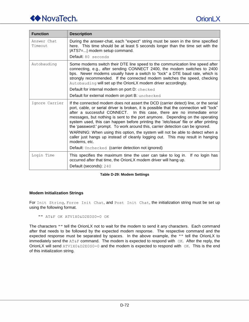
OrionLX
D-72
Function Description
Answer Chat
Timeout
During the answer-chat, each "expect" string must be seen in the time specified here. This time should be at least 5 seconds longer than the time set with the |ATS7=...| modem setup command.
Default: 80 seconds
Autobauding Some modems switch their DTE line speed to the communication line speed after connecting, e.g., after sending CONNECT 2400, the modem switches to 2400 bps. Newer modems usually have a switch to "lock" a DTE baud rate, which is strongly recommended. If the connected modem switches the speed, checking
Autobauding will set up the OrionLX modem driver accordingly.
Default for internal modem on port D: checked
Default for external modem on port B: unchecked
Ignore Carrier If the connected modem does not assert the DCD (carrier detect) line, or the serial port, cable, or serial driver is broken, it is possible that the connection will “lock” after a successful CONNECT. In this case, there are no immediate error messages, but nothing is sent to the port anymore. Depending on the operating system used, this can happen before printing the „/etc/issue' file or after printing the „password:' prompt. To work around this, carrier detection can be ignored.
WARNING: When using this option, the system will not be able to detect when a caller just hangs up instead of cleanly logging out. This may result in hanging modems, etc.
Default: Unchecked (carrier detection not ignored)
Login Time This specifies the maximum time the user can take to log in. If no login has occurred after that time, the OrionLX modem driver will hang up.
Default (seconds): 240
Table D-29: Modem Settings
Modem Initialization Strings
For Init String, Force Init Chat, and Post Init Chat, the initialization string must be set up
using the following format.
"" AT&F OK ATV1X0&D2E0S0=0 OK
The characters "" tell the OrionLX not to wait for the modem to send it any characters. Each command
after that needs to be followed by the expected modem response. The respective command and the
expected response must be separated by spaces. In the above example, the "" tell the OrionLX to
immediately send the AT&F command. The modem is expected to respond with OK. After the reply, the
OrionLX will send ATV1X0&D2E0S0=0 and the modem is expected to respond with OK. This is the end
of this initialization string.
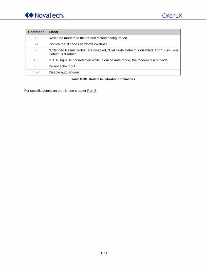
OrionLX
D-73
Command Effect
&F Reset the modem to the default factory configuration.
V1 Display result codes as words (verbose).
X0 “Extended Result Codes” are disabled, “Dial Code Detect” is disabled, and “Busy Tone Detect” is disabled.
&D2 If DTR signal is not detected while in online data mode, the modem disconnects.
E0 Do not echo input.
S0=0 Disable auto answer.
Table D-30: Modem Initialization Commands
For specific details on port B, see chapter Port B.
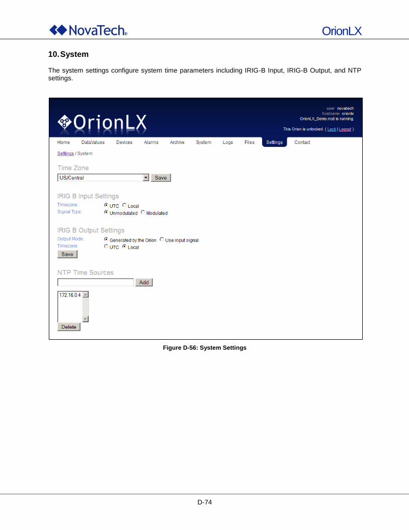
OrionLX
D-74
10. System The system settings configure system time parameters including IRIG-B Input, IRIG-B Output, and NTP settings.
Figure D-56: System Settings
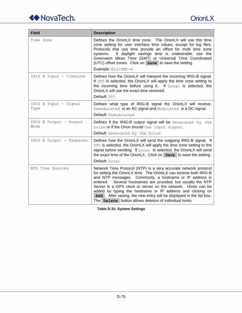
OrionLX
D-75
Field Description
Time Zone Defines the OrionLX time zone. The OrionLX will use this time zone setting for user interface time values, except for log files. Protocols that use time provide an offset for multi time zone systems. If daylight savings time is undesirable, use the Greenwich Mean Time (GMT) or Universal Time Coordinated (UTC) offset zones. Click on Save to save the setting.
Example: Etc/GMT-6
IRIG B Input - Timezone Defines how the OrionLX will interpret the incoming IRIG-B signal.
If UTC is selected, the OrionLX will apply the time zone setting to
the incoming time before using it. If Local is selected, the
OrionLX will use the exact time received.
Default: UTC
IRIG B Input - Signal
Type
Defines what type of IRIG-B signal the OrionLX will receive.
Unmodulated is an AC signal and Modulated is a DC signal.
Default: Unmodulated
IRIG B Output – Output
Mode
Defines if the IRIG-B output signal will be Generated by the
Orion or if the Orion should Use input signal.
Default: Generated by the Orion
IRIG B Output - Timezone Defines how the OrionLX will send the outgoing IRIG-B signal. If
UTC is selected, the OrionLX will apply the time zone setting to the
signal before sending. If Local is selected, the OrionLX will send
the exact time of the OrionLX. Click on Save to save the setting.
Default: Local
NTP Time Sources Network Time Protocol (NTP) is a very accurate network protocol for setting the OrionLX time. The OrionLX can receive both IRIG-B and NTP messages. Commonly, a hostname or IP address is entered. Several hostnames are provided, but usually the NTP Server is a GPS clock or server on the network. Hosts can be added by typing the hostname or IP address and clicking on Add . After saving, the new entry will be displayed in the list box.
The Delete button allows deletion of individual hosts.
Table D-31: System Settings
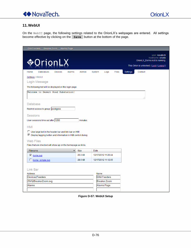
OrionLX
D-76
11. WebUI
On the WebUI page, the following settings related to the OrionLX‟s webpages are entered. All settings
become effective by clicking on the Save button at the bottom of the page.
Figure D-57: WebUI Setup
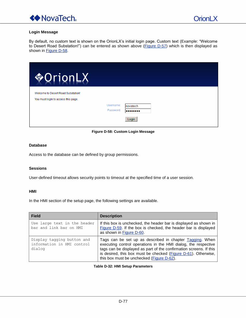
OrionLX
D-77
Login Message By default, no custom text is shown on the OrionLX‟s initial login page. Custom text (Example: “Welcome to Desert Road Substation!”) can be entered as shown above (Figure D-57) which is then displayed as shown in Figure D-58.
Figure D-58: Custom Login Message
Database Access to the database can be defined by group permissions. Sessions User-defined timeout allows security points to timeout at the specified time of a user session. HMI In the HMI section of the setup page, the following settings are available.
Field Description
Use large text in the header
bar and link bar on HMI
If this box is unchecked, the header bar is displayed as shown in Figure D-59. If the box is checked, the header bar is displayed as shown in Figure D-60.
Display tagging button and
information in HMI control
dialog
Tags can be set up as described in chapter Tagging. When executing control operations in the HMI dialog, the respective tags can be displayed as part of the confirmation screens. If this is desired, this box must be checked (Figure D-61). Otherwise, this box must be unchecked (Figure D-62).
Table D-32: HMI Setup Parameters
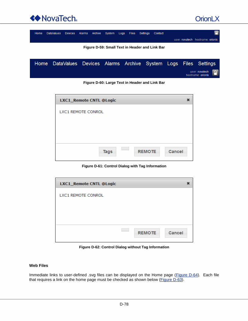
OrionLX
D-78
Figure D-59: Small Text in Header and Link Bar
Figure D-60: Large Text in Header and Link Bar
Figure D-61: Control Dialog with Tag Information
Figure D-62: Control Dialog without Tag Information
Web Files Immediate links to user-defined .svg files can be displayed on the Home page (Figure D-64). Each file that requires a link on the home page must be checked as shown below (Figure D-63).
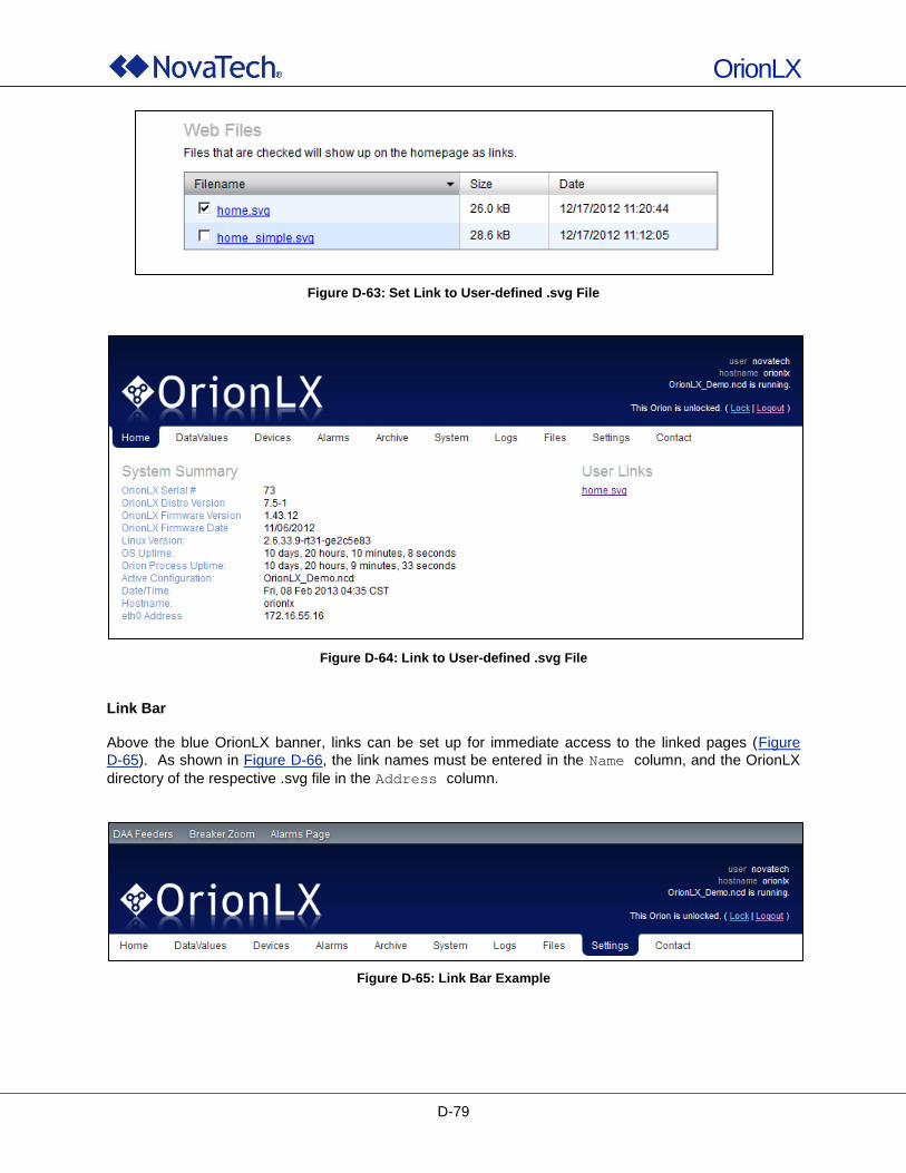
OrionLX
D-79
Figure D-63: Set Link to User-defined .svg File
Figure D-64: Link to User-defined .svg File
Link Bar Above the blue OrionLX banner, links can be set up for immediate access to the linked pages (Figure
D-65). As shown in Figure D-66, the link names must be entered in the Name column, and the OrionLX
directory of the respective .svg file in the Address column.
Figure D-65: Link Bar Example
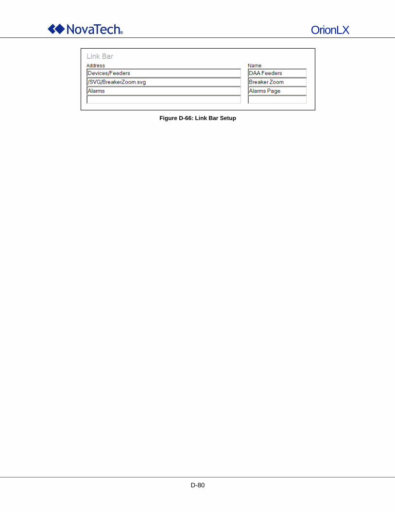
OrionLX
D-80
Figure D-66: Link Bar Setup
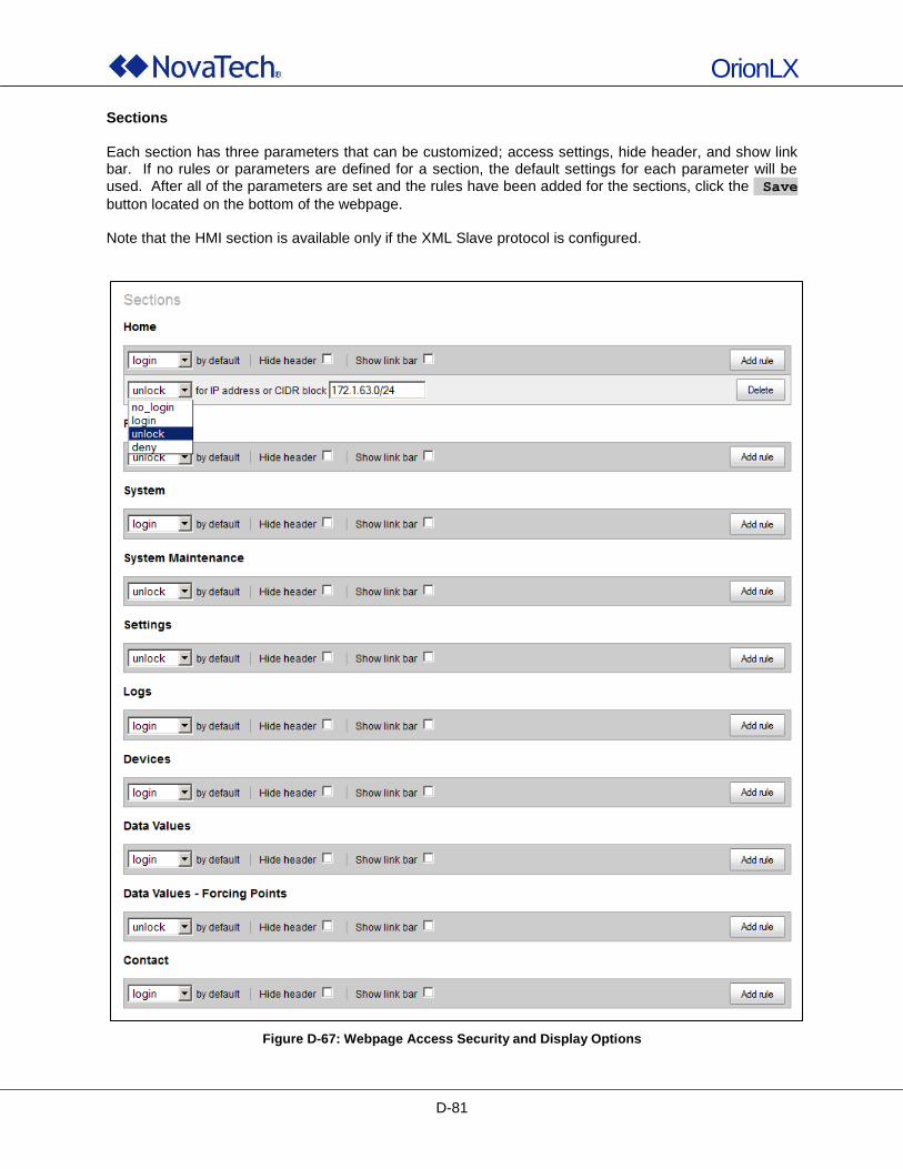
OrionLX
D-81
Sections Each section has three parameters that can be customized; access settings, hide header, and show link bar. If no rules or parameters are defined for a section, the default settings for each parameter will be used. After all of the parameters are set and the rules have been added for the sections, click the Save
button located on the bottom of the webpage. Note that the HMI section is available only if the XML Slave protocol is configured.
Figure D-67: Webpage Access Security and Display Options
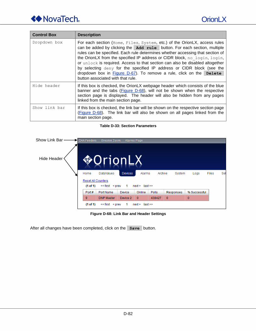
OrionLX
D-82
Control Box Description
Dropdown box For each section (Home, Files, System, etc.) of the OrionLX, access rules
can be added by clicking the Add rule button. For each section, multiple
rules can be specified. Each rule determines whether accessing that section of
the OrionLX from the specified IP address or CIDR block, no_login, login,
or unlock is required. Access to that section can also be disabled altogether
by selecting deny for the specified IP address or CIDR block (see the
dropdown box in Figure D-67). To remove a rule, click on the Delete
button associated with that rule.
Hide header If this box is checked, the OrionLX webpage header which consists of the blue banner and the tabs (Figure D-68), will not be shown when the respective section page is displayed. The header will also be hidden from any pages linked from the main section page.
Show link bar If this box is checked, the link bar will be shown on the respective section page (Figure D-68). The link bar will also be shown on all pages linked from the main section page.
Table D-33: Section Parameters
Figure D-68: Link Bar and Header Settings
After all changes have been completed, click on the Save button.
Show Link Bar
Hide Header
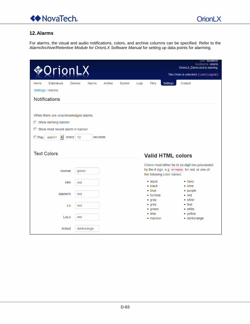
OrionLX
D-83
12. Alarms For alarms, the visual and audio notifications, colors, and archive columns can be specified. Refer to the Alarm/Archive/Retentive Module for OrionLX Software Manual for setting up data points for alarming.
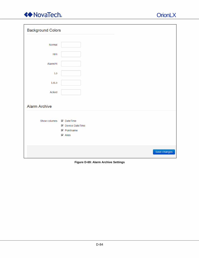
OrionLX
D-84
Figure D-69: Alarm Archive Settings
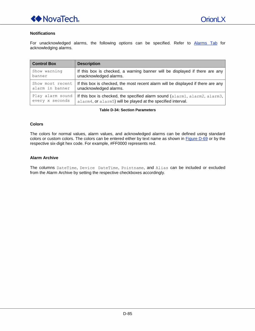
OrionLX
D-85
Notifications For unacknowledged alarms, the following options can be specified. Refer to Alarms Tab for acknowledging alarms.
Control Box Description
Show warning
banner
If this box is checked, a warning banner will be displayed if there are any unacknowledged alarms.
Show most recent
alarm in banner
If this box is checked, the most recent alarm will be displayed if there are any unacknowledged alarms.
Play alarm sound
every x seconds
If this box is checked, the specified alarm sound (alarm1, alarm2, alarm3,
alarm4, or alarm5) will be played at the specified interval.
Table D-34: Section Parameters
Colors The colors for normal values, alarm values, and acknowledged alarms can be defined using standard colors or custom colors. The colors can be entered either by text name as shown in Figure D-69 or by the respective six-digit hex code. For example, #FF0000 represents red. Alarm Archive
The columns DateTime, Device DateTime, Pointname, and Alias can be included or excluded
from the Alarm Archive by setting the respective checkboxes accordingly.
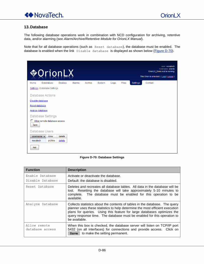
OrionLX
D-86
13. Database The following database operations work in combination with NCD configuration for archiving, retentive data, and/or alarming (see Alarm/Archive/Retentive Module for OrionLX Manual).
Note that for all database operations (such as Reset database), the database must be enabled. The
database is enabled when the link Disable database is displayed as shown below (Figure D-70).
Figure D-70: Database Settings
Function Description
Enable Database
Disable Database
Activate or deactivate the database.
Default: the database is disabled.
Reset Database Deletes and recreates all database tables. All data in the database will be lost. Resetting the database will take approximately 5-10 minutes to complete. The database must be enabled for this operation to be available.
Analyze Database Collects statistics about the contents of tables in the database. The query planner uses these statistics to help determine the most efficient execution plans for queries. Using this feature for large databases optimizes the query response time. The database must be enabled for this operation to be available.
Allow remote
database access
When this box is checked, the database server will listen on TCP/IP port 5432 (on all interfaces) for connections and provide access. Click on Save to make the setting permanent.
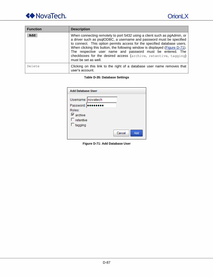
OrionLX
D-87
Function Description
Add When connecting remotely to port 5432 using a client such as pgAdmin, or a driver such as psqlODBC, a username and password must be specified to connect. This option permits access for the specified database users. When clicking this button, the following window is displayed (Figure D-71). The respective user name and password must be entered. The
checkboxes for the desired access (archive, retentive, tagging)
must be set as well.
Delete Clicking on this link to the right of a database user name removes that user‟s account.
Table D-35: Database Settings
Figure D-71: Add Database User
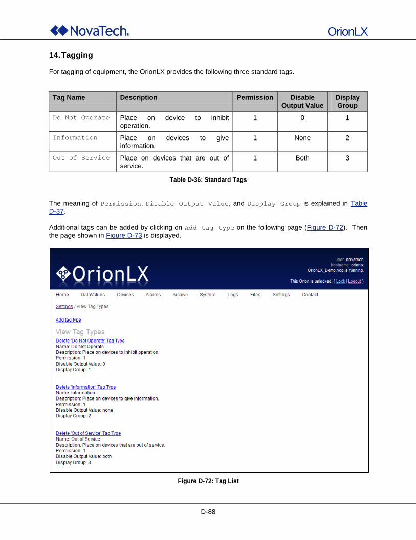
OrionLX
D-88
14. Tagging For tagging of equipment, the OrionLX provides the following three standard tags.
Tag Name Description Permission Disable Output Value
Display Group
Do Not Operate Place on device to inhibit operation.
1 0 1
Information Place on devices to give information.
1 None 2
Out of Service Place on devices that are out of service.
1 Both 3
Table D-36: Standard Tags
The meaning of Permission, Disable Output Value, and Display Group is explained in Table
D-37.
Additional tags can be added by clicking on Add tag type on the following page (Figure D-72). Then
the page shown in Figure D-73 is displayed.
Figure D-72: Tag List
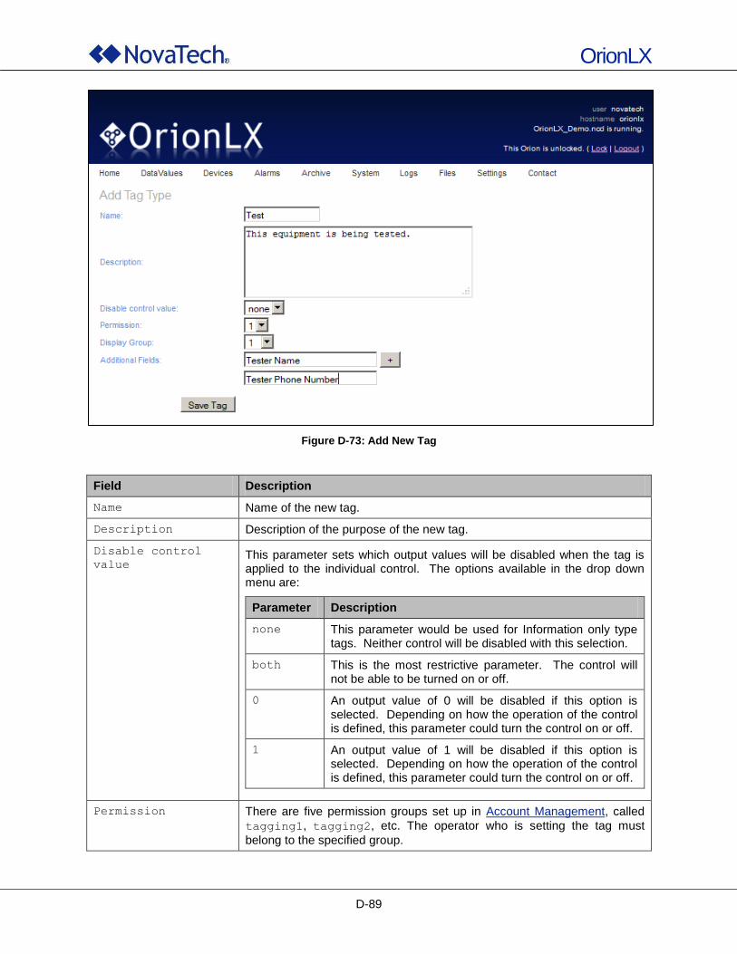
OrionLX
D-89
Figure D-73: Add New Tag
Field Description
Name Name of the new tag.
Description Description of the purpose of the new tag.
Disable control
value This parameter sets which output values will be disabled when the tag is applied to the individual control. The options available in the drop down menu are:
Parameter Description
none This parameter would be used for Information only type tags. Neither control will be disabled with this selection.
both This is the most restrictive parameter. The control will not be able to be turned on or off.
0 An output value of 0 will be disabled if this option is selected. Depending on how the operation of the control is defined, this parameter could turn the control on or off.
1 An output value of 1 will be disabled if this option is selected. Depending on how the operation of the control is defined, this parameter could turn the control on or off.
Permission There are five permission groups set up in Account Management, called
tagging1, tagging2, etc. The operator who is setting the tag must
belong to the specified group.
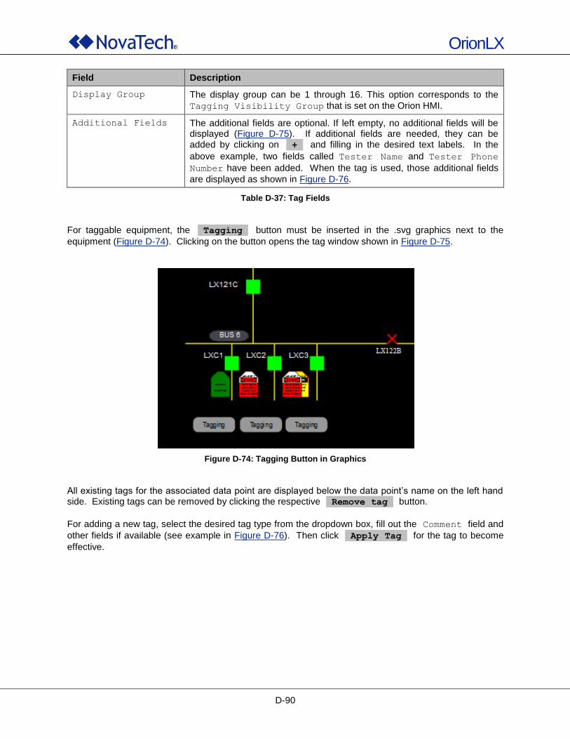
OrionLX
D-90
Field Description
Display Group The display group can be 1 through 16. This option corresponds to the
Tagging Visibility Group that is set on the Orion HMI.
Additional Fields The additional fields are optional. If left empty, no additional fields will be displayed (Figure D-75). If additional fields are needed, they can be added by clicking on + and filling in the desired text labels. In the
above example, two fields called Tester Name and Tester Phone
Number have been added. When the tag is used, those additional fields
are displayed as shown in Figure D-76.
Table D-37: Tag Fields
For taggable equipment, the Tagging button must be inserted in the .svg graphics next to the
equipment (Figure D-74). Clicking on the button opens the tag window shown in Figure D-75.
Figure D-74: Tagging Button in Graphics
All existing tags for the associated data point are displayed below the data point‟s name on the left hand side. Existing tags can be removed by clicking the respective Remove tag button.
For adding a new tag, select the desired tag type from the dropdown box, fill out the Comment field and
other fields if available (see example in Figure D-76). Then click Apply Tag for the tag to become
effective.
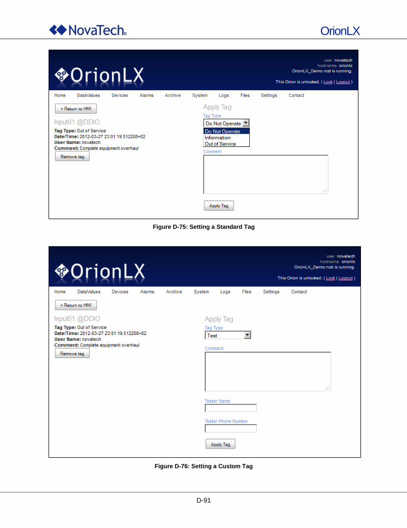
OrionLX
D-91
Figure D-75: Setting a Standard Tag
Figure D-76: Setting a Custom Tag
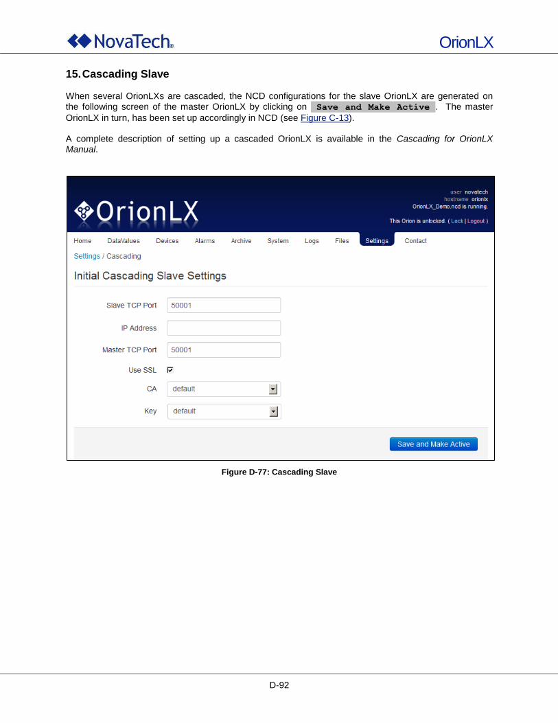
OrionLX
D-92
15. Cascading Slave When several OrionLXs are cascaded, the NCD configurations for the slave OrionLX are generated on the following screen of the master OrionLX by clicking on Save and Make Active . The master
OrionLX in turn, has been set up accordingly in NCD (see Figure C-13). A complete description of setting up a cascaded OrionLX is available in the Cascading for OrionLX Manual.
Figure D-77: Cascading Slave
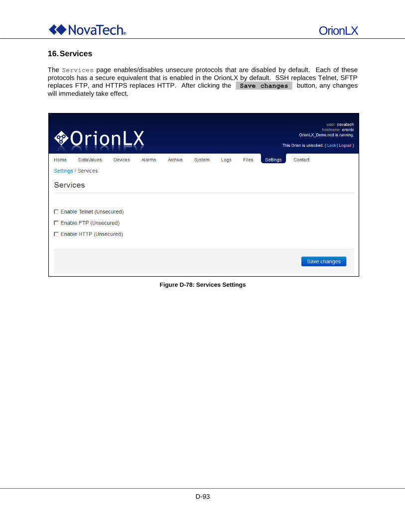
OrionLX
D-93
16. Services
The Services page enables/disables unsecure protocols that are disabled by default. Each of these
protocols has a secure equivalent that is enabled in the OrionLX by default. SSH replaces Telnet, SFTP replaces FTP, and HTTPS replaces HTTP. After clicking the Save changes button, any changes
will immediately take effect.
Figure D-78: Services Settings
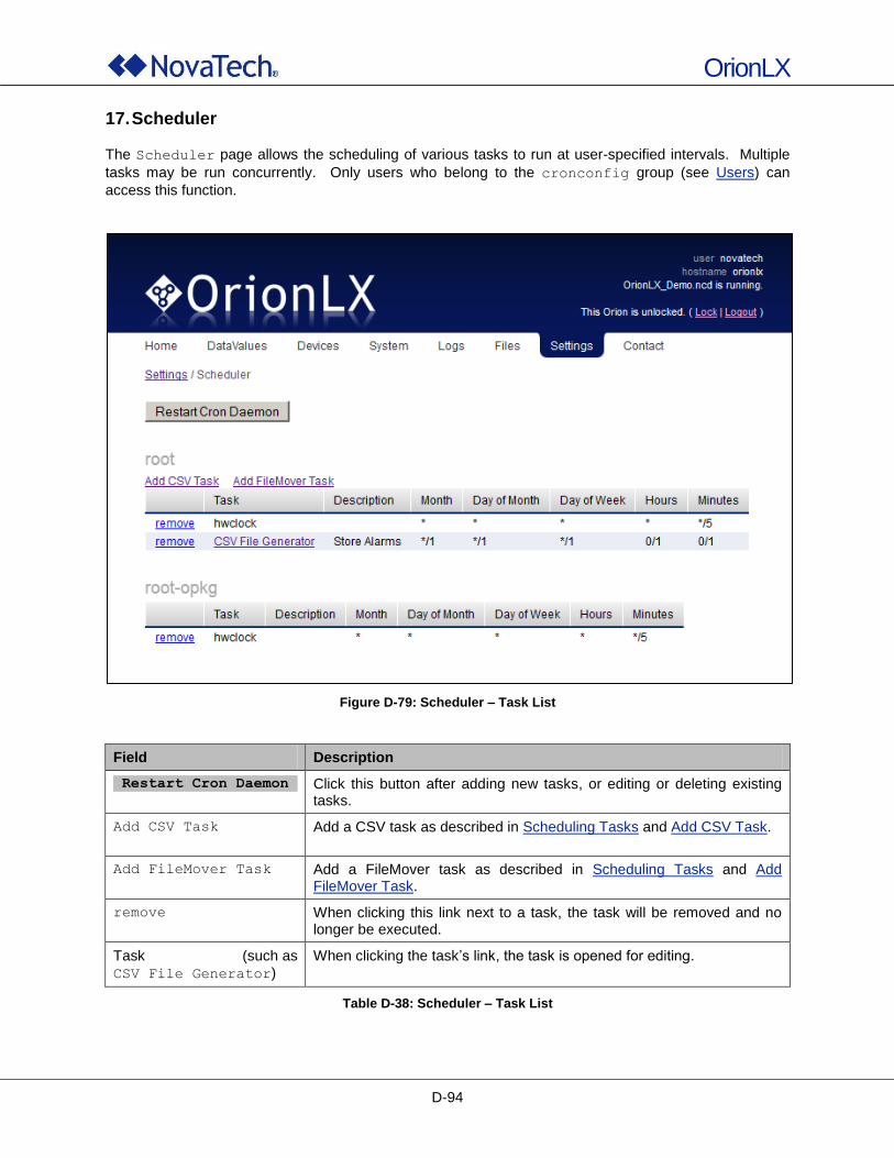
OrionLX
D-94
17. Scheduler
The Scheduler page allows the scheduling of various tasks to run at user-specified intervals. Multiple
tasks may be run concurrently. Only users who belong to the cronconfig group (see Users) can
access this function.
Figure D-79: Scheduler – Task List
Field Description
Restart Cron Daemon Click this button after adding new tasks, or editing or deleting existing tasks.
Add CSV Task Add a CSV task as described in Scheduling Tasks and Add CSV Task.
Add FileMover Task Add a FileMover task as described in Scheduling Tasks and Add FileMover Task.
remove When clicking this link next to a task, the task will be removed and no longer be executed.
Task (such as
CSV File Generator)
When clicking the task‟s link, the task is opened for editing.
Table D-38: Scheduler – Task List
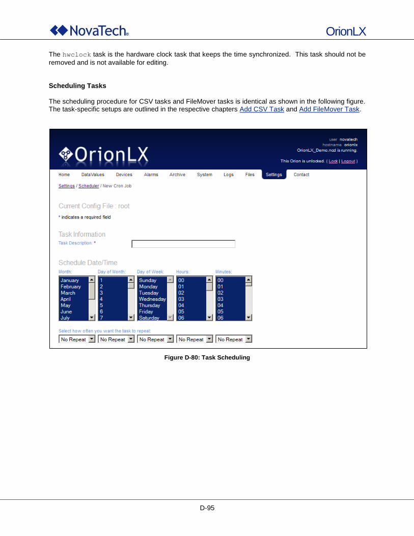
OrionLX
D-95
The hwclock task is the hardware clock task that keeps the time synchronized. This task should not be
removed and is not available for editing. Scheduling Tasks The scheduling procedure for CSV tasks and FileMover tasks is identical as shown in the following figure. The task-specific setups are outlined in the respective chapters Add CSV Task and Add FileMover Task.
Figure D-80: Task Scheduling
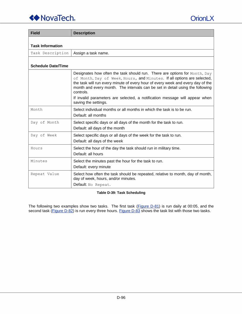
OrionLX
D-96
Field Description
Task Information
Task Description Assign a task name.
Schedule Date/Time
Designates how often the task should run. There are options for Month, Day
of Month, Day of Week, Hours, and Minutes. If all options are selected,
the task will run every minute of every hour of every week and every day of the month and every month. The intervals can be set in detail using the following controls.
If invalid parameters are selected, a notification message will appear when saving the settings.
Month Select individual months or all months in which the task is to be run.
Default: all months
Day of Month Select specific days or all days of the month for the task to run.
Default: all days of the month
Day of Week Select specific days or all days of the week for the task to run.
Default: all days of the week
Hours Select the hour of the day the task should run in military time.
Default: all hours
Minutes Select the minutes past the hour for the task to run.
Default: every minute
Repeat Value Select how often the task should be repeated, relative to month, day of month, day of week, hours, and/or minutes.
Default: No Repeat.
Table D-39: Task Scheduling
The following two examples show two tasks. The first task (Figure D-81) is run daily at 00:05, and the second task (Figure D-82) is run every three hours. Figure D-83 shows the task list with those two tasks.
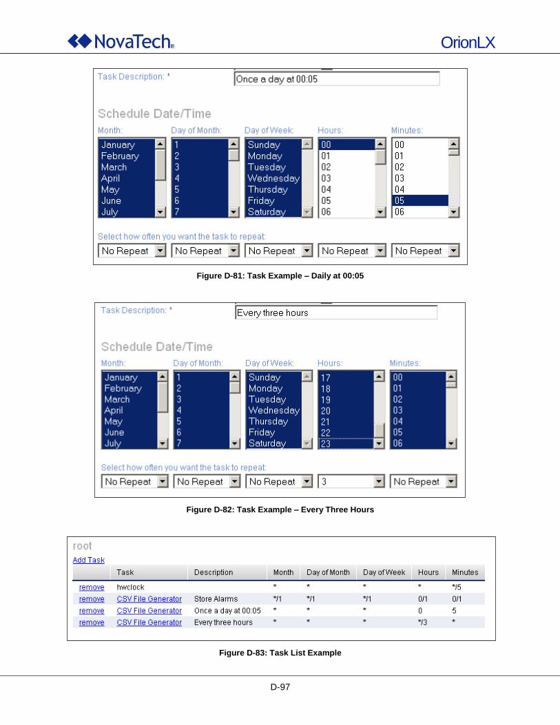
OrionLX
D-97
Figure D-81: Task Example – Daily at 00:05
Figure D-82: Task Example – Every Three Hours
Figure D-83: Task List Example
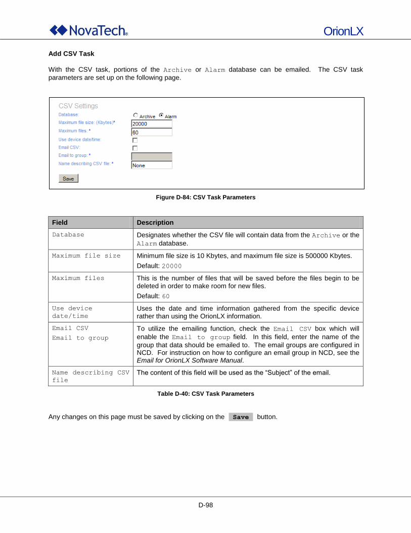
OrionLX
D-98
Add CSV Task
With the CSV task, portions of the Archive or Alarm database can be emailed. The CSV task
parameters are set up on the following page.
Figure D-84: CSV Task Parameters
Field Description
Database Designates whether the CSV file will contain data from the Archive or the
Alarm database.
Maximum file size Minimum file size is 10 Kbytes, and maximum file size is 500000 Kbytes.
Default: 20000
Maximum files This is the number of files that will be saved before the files begin to be deleted in order to make room for new files.
Default: 60
Use device
date/time
Uses the date and time information gathered from the specific device rather than using the OrionLX information.
Email CSV
Email to group
To utilize the emailing function, check the Email CSV box which will
enable the Email to group field. In this field, enter the name of the
group that data should be emailed to. The email groups are configured in NCD. For instruction on how to configure an email group in NCD, see the Email for OrionLX Software Manual.
Name describing CSV
file
The content of this field will be used as the “Subject” of the email.
Table D-40: CSV Task Parameters
Any changes on this page must be saved by clicking on the Save button.

OrionLX
D-99
Add FileMover Task With the FileMover task, files in the OrionLX can be transferred to a host computer using FTP or SFTP. The FileMover task parameters are set up on the following page. Note: The FileMover software package must be installed on the OrionLX for this option to be
available.
Figure D-85: FileMover Task Parameters
Field Description
ftp sftp Select the protocol for the file transfer.
Path Path in the OrionLX file system of the file to be transferred.
Private Key Path to the private key file used for encrypting the transferred file. This is only needed when using SFTP.
IP Address IP address of the host computer to which the file is transferred.
Port Port of the host computer used for file transfer.
Path Path in the host computer file system where the transferred file is stored.
Username Username for login at the host computer.
Password Password for login at the host computer.
Delete on success If this box is checked, the specified file will be deleted in the OrionLX file system upon successful transfer to the host computer.
Table D-41: FileMover Task Parameters
Any changes on this page must be saved by clicking on the Save button.

OrionLX
E-1
E. OrionLX MMI
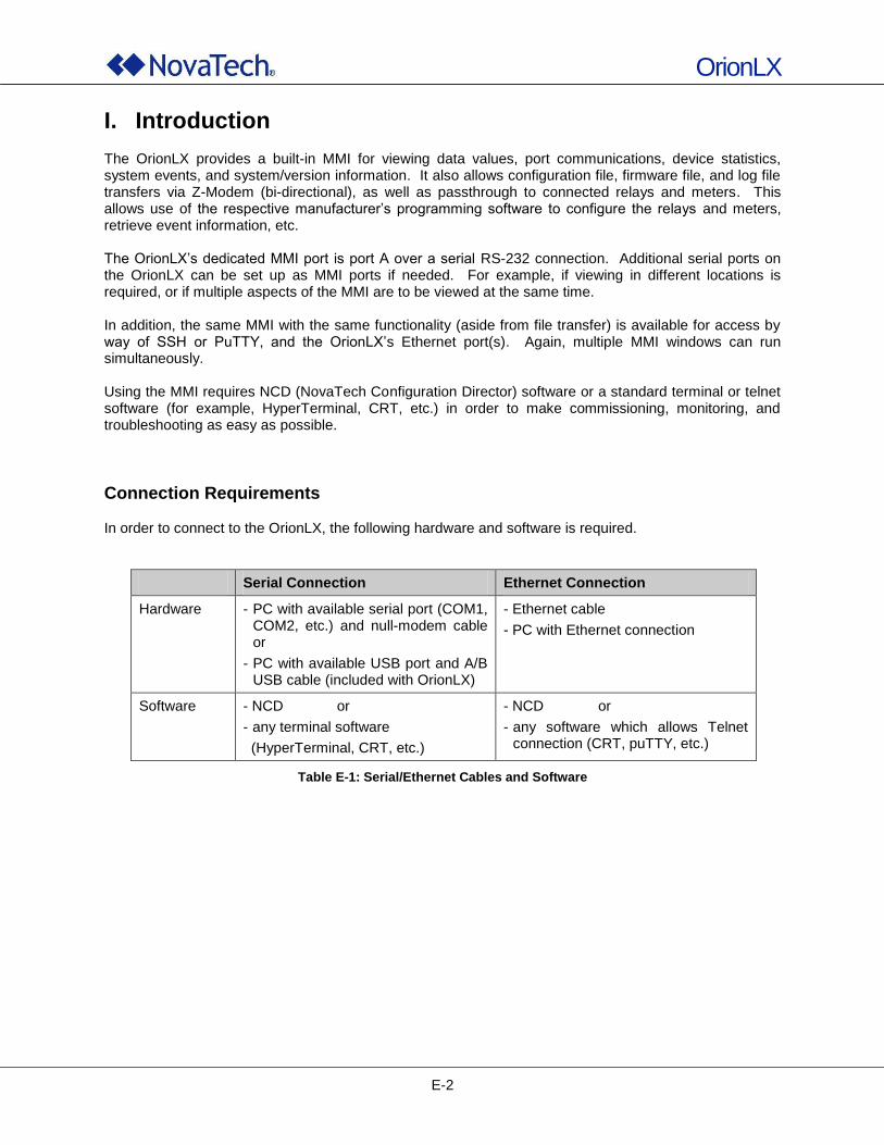
OrionLX
E-2
I. Introduction The OrionLX provides a built-in MMI for viewing data values, port communications, device statistics, system events, and system/version information. It also allows configuration file, firmware file, and log file transfers via Z-Modem (bi-directional), as well as passthrough to connected relays and meters. This allows use of the respective manufacturer‟s programming software to configure the relays and meters, retrieve event information, etc. The OrionLX‟s dedicated MMI port is port A over a serial RS-232 connection. Additional serial ports on the OrionLX can be set up as MMI ports if needed. For example, if viewing in different locations is required, or if multiple aspects of the MMI are to be viewed at the same time. In addition, the same MMI with the same functionality (aside from file transfer) is available for access by way of SSH or PuTTY, and the OrionLX‟s Ethernet port(s). Again, multiple MMI windows can run simultaneously. Using the MMI requires NCD (NovaTech Configuration Director) software or a standard terminal or telnet software (for example, HyperTerminal, CRT, etc.) in order to make commissioning, monitoring, and troubleshooting as easy as possible.
Connection Requirements In order to connect to the OrionLX, the following hardware and software is required.
Serial Connection Ethernet Connection
Hardware - PC with available serial port (COM1, COM2, etc.) and null-modem cable or
- PC with available USB port and A/B USB cable (included with OrionLX)
- Ethernet cable
- PC with Ethernet connection
Software - NCD or
- any terminal software
(HyperTerminal, CRT, etc.)
- NCD or
- any software which allows Telnet connection (CRT, puTTY, etc.)
Table E-1: Serial/Ethernet Cables and Software
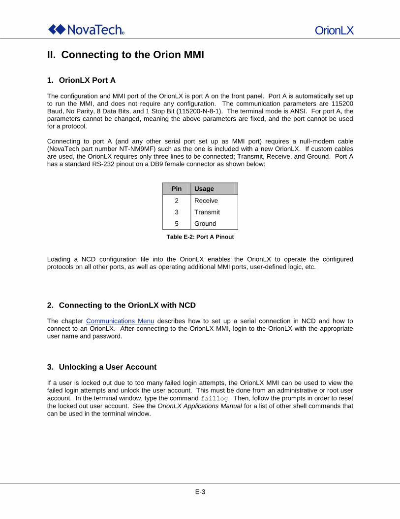
OrionLX
E-3
II. Connecting to the Orion MMI
1. OrionLX Port A The configuration and MMI port of the OrionLX is port A on the front panel. Port A is automatically set up to run the MMI, and does not require any configuration. The communication parameters are 115200 Baud, No Parity, 8 Data Bits, and 1 Stop Bit (115200-N-8-1). The terminal mode is ANSI. For port A, the parameters cannot be changed, meaning the above parameters are fixed, and the port cannot be used for a protocol. Connecting to port A (and any other serial port set up as MMI port) requires a null-modem cable (NovaTech part number NT-NM9MF) such as the one is included with a new OrionLX. If custom cables are used, the OrionLX requires only three lines to be connected; Transmit, Receive, and Ground. Port A has a standard RS-232 pinout on a DB9 female connector as shown below:
Pin Usage
2 Receive
3 Transmit
5 Ground
Table E-2: Port A Pinout Loading a NCD configuration file into the OrionLX enables the OrionLX to operate the configured protocols on all other ports, as well as operating additional MMI ports, user-defined logic, etc.
2. Connecting to the OrionLX with NCD The chapter Communications Menu describes how to set up a serial connection in NCD and how to connect to an OrionLX. After connecting to the OrionLX MMI, login to the OrionLX with the appropriate user name and password.
3. Unlocking a User Account If a user is locked out due to too many failed login attempts, the OrionLX MMI can be used to view the failed login attempts and unlock the user account. This must be done from an administrative or root user
account. In the terminal window, type the command faillog. Then, follow the prompts in order to reset
the locked out user account. See the OrionLX Applications Manual for a list of other shell commands that can be used in the terminal window.
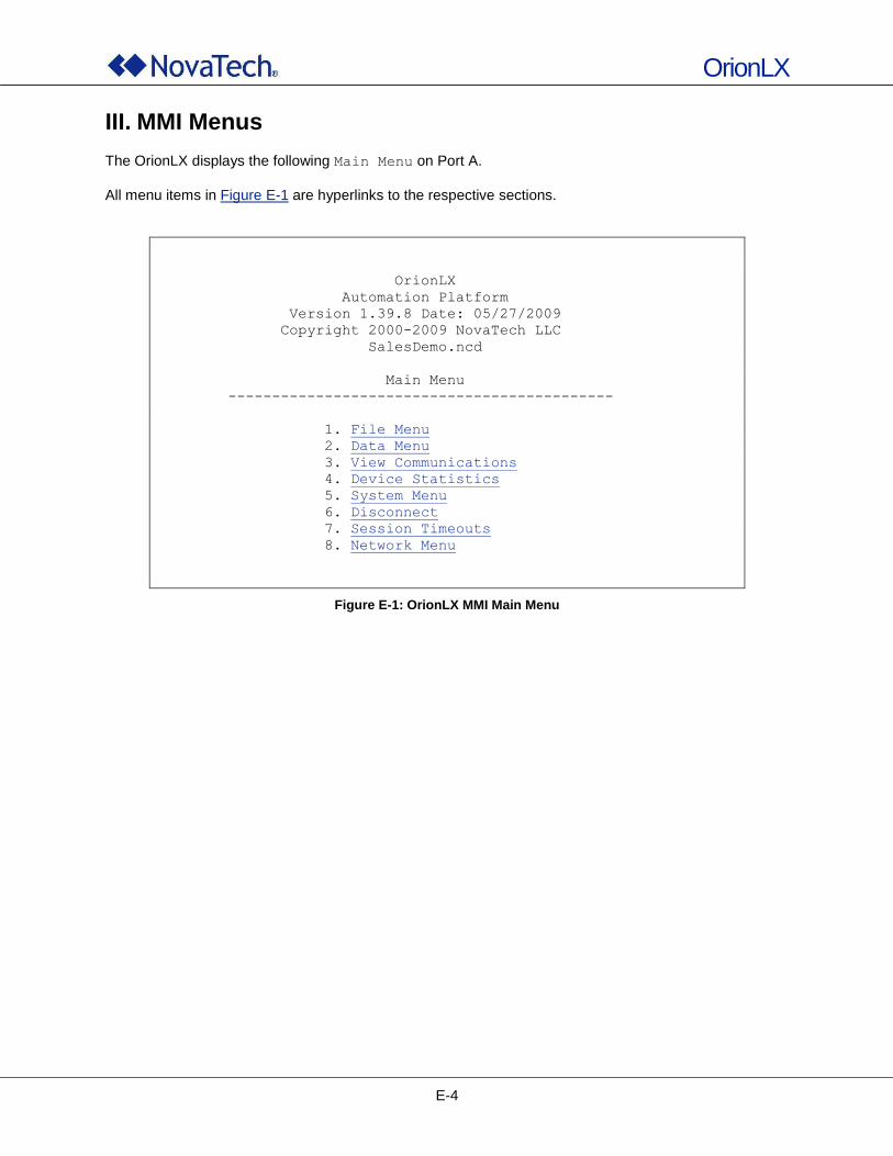
OrionLX
E-4
III. MMI Menus
The OrionLX displays the following Main Menu on Port A.
All menu items in Figure E-1 are hyperlinks to the respective sections.
OrionLX
Automation Platform
Version 1.39.8 Date: 05/27/2009
Copyright 2000-2009 NovaTech LLC
SalesDemo.ncd
Main Menu
--------------------------------------------
1. File Menu
2. Data Menu
3. View Communications
4. Device Statistics
5. System Menu
6. Disconnect
7. Session Timeouts
8. Network Menu
Figure E-1: OrionLX MMI Main Menu
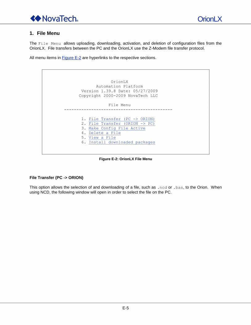
OrionLX
E-5
1. File Menu
The File Menu allows uploading, downloading, activation, and deletion of configuration files from the
OrionLX. File transfers between the PC and the OrionLX use the Z-Modem file transfer protocol. All menu items in Figure E-2 are hyperlinks to the respective sections.
OrionLX
Automation Platform
Version 1.39.8 Date: 05/27/2009
Copyright 2000-2009 NovaTech LLC
File Menu
--------------------------------------------
1. File Transfer (PC -> ORION)
2. File Transfer (ORION -> PC)
3. Make Config File Active
4. Delete a File
5. View a File
6. Install downloaded packages
Figure E-2: OrionLX File Menu
File Transfer (PC -> ORION)
This option allows the selection of and downloading of a file, such as .ncd or .bas, to the Orion. When
using NCD, the following window will open in order to select the file on the PC.
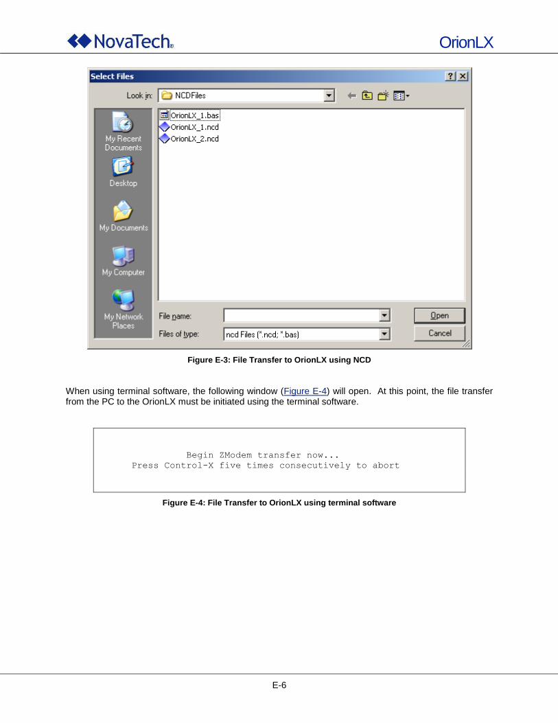
OrionLX
E-6
Figure E-3: File Transfer to OrionLX using NCD
When using terminal software, the following window (Figure E-4) will open. At this point, the file transfer from the PC to the OrionLX must be initiated using the terminal software.
Begin ZModem transfer now...
Press Control-X five times consecutively to abort
Figure E-4: File Transfer to OrionLX using terminal software
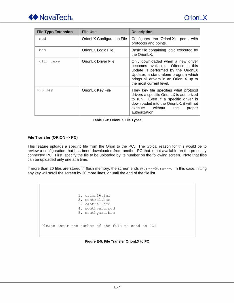
OrionLX
E-7
File Type/Extension File Use Description
.ncd OrionLX Configuration File Configures the OrionLX‟s ports with protocols and points.
.bas OrionLX Logic File Basic file containing logic executed by the OrionLX.
.dll, .exe OrionLX Driver File Only downloaded when a new driver becomes available. Oftentimes this update is performed by the OrionLX Updater, a stand-alone program which brings all drivers in an OrionLX up to the most current level.
o16.key OrionLX Key File They key file specifies what protocol drivers a specific OrionLX is authorized to run. Even if a specific driver is downloaded into the OrionLX, it will not execute without the proper authorization.
Table E-3: OrionLX File Types
File Transfer (ORION -> PC) This feature uploads a specific file from the Orion to the PC. The typical reason for this would be to review a configuration that has been downloaded from another PC that is not available on the presently connected PC. First, specify the file to be uploaded by its number on the following screen. Note that files can be uploaded only one at a time.
If more than 20 files are stored in flash memory, the screen ends with ---More---. In this case, hitting
any key will scroll the screen by 20 more lines, or until the end of the file list.
1. orion16.ini
2. central.bas
3. central.ncd
4. southyard.ncd
5. southyard.bas
Please enter the number of the file to send to PC:
Figure E-5: File Transfer OrionLX to PC
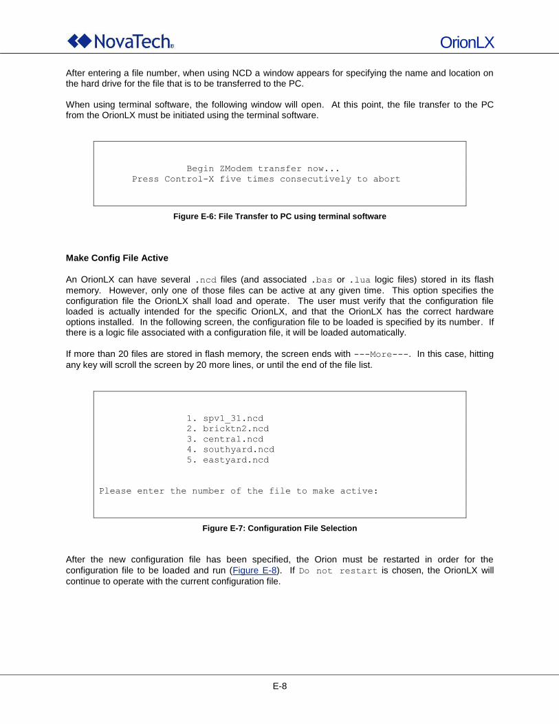
OrionLX
E-8
After entering a file number, when using NCD a window appears for specifying the name and location on the hard drive for the file that is to be transferred to the PC. When using terminal software, the following window will open. At this point, the file transfer to the PC from the OrionLX must be initiated using the terminal software.
Begin ZModem transfer now...
Press Control-X five times consecutively to abort
Figure E-6: File Transfer to PC using terminal software
Make Config File Active
An OrionLX can have several .ncd files (and associated .bas or .lua logic files) stored in its flash
memory. However, only one of those files can be active at any given time. This option specifies the configuration file the OrionLX shall load and operate. The user must verify that the configuration file loaded is actually intended for the specific OrionLX, and that the OrionLX has the correct hardware options installed. In the following screen, the configuration file to be loaded is specified by its number. If there is a logic file associated with a configuration file, it will be loaded automatically.
If more than 20 files are stored in flash memory, the screen ends with ---More---. In this case, hitting
any key will scroll the screen by 20 more lines, or until the end of the file list.
1. spv1_31.ncd
2. bricktn2.ncd
3. central.ncd
4. southyard.ncd
5. eastyard.ncd
Please enter the number of the file to make active:
Figure E-7: Configuration File Selection
After the new configuration file has been specified, the Orion must be restarted in order for the
configuration file to be loaded and run (Figure E-8). If Do not restart is chosen, the OrionLX will
continue to operate with the current configuration file.
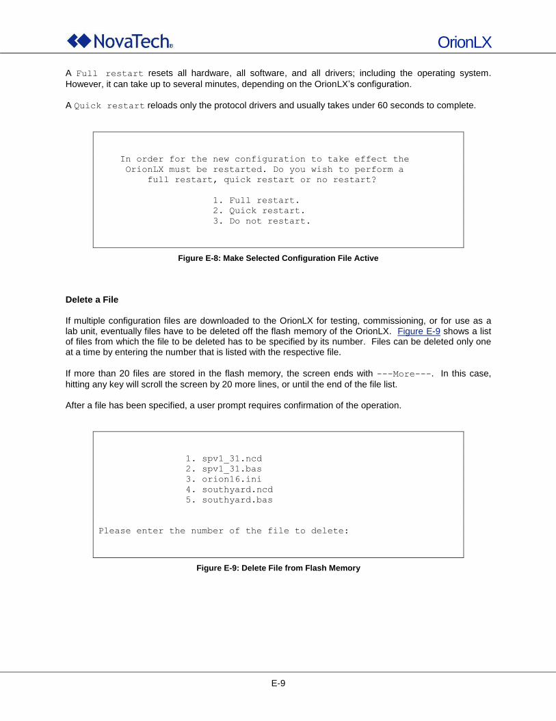
OrionLX
E-9
A Full restart resets all hardware, all software, and all drivers; including the operating system.
However, it can take up to several minutes, depending on the OrionLX‟s configuration.
A Quick restart reloads only the protocol drivers and usually takes under 60 seconds to complete.
In order for the new configuration to take effect the
OrionLX must be restarted. Do you wish to perform a
full restart, quick restart or no restart?
1. Full restart.
2. Quick restart.
3. Do not restart.
Figure E-8: Make Selected Configuration File Active
Delete a File If multiple configuration files are downloaded to the OrionLX for testing, commissioning, or for use as a lab unit, eventually files have to be deleted off the flash memory of the OrionLX. Figure E-9 shows a list of files from which the file to be deleted has to be specified by its number. Files can be deleted only one at a time by entering the number that is listed with the respective file.
If more than 20 files are stored in the flash memory, the screen ends with ---More---. In this case,
hitting any key will scroll the screen by 20 more lines, or until the end of the file list. After a file has been specified, a user prompt requires confirmation of the operation.
1. spv1_31.ncd
2. spv1_31.bas
3. orion16.ini
4. southyard.ncd
5. southyard.bas
Please enter the number of the file to delete:
Figure E-9: Delete File from Flash Memory
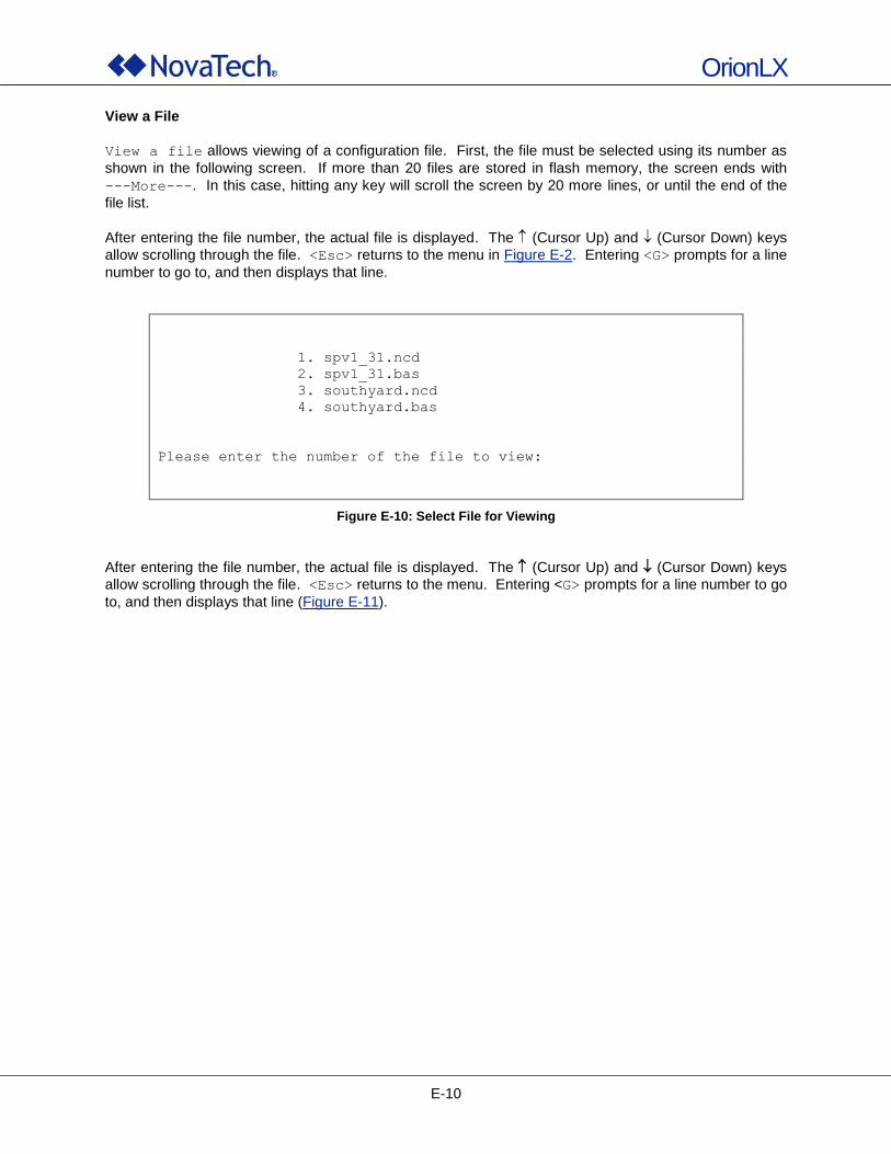
OrionLX
E-10
View a File
View a file allows viewing of a configuration file. First, the file must be selected using its number as
shown in the following screen. If more than 20 files are stored in flash memory, the screen ends with
---More---. In this case, hitting any key will scroll the screen by 20 more lines, or until the end of the
file list.
After entering the file number, the actual file is displayed. The (Cursor Up) and (Cursor Down) keys
allow scrolling through the file. <Esc> returns to the menu in Figure E-2. Entering <G> prompts for a line
number to go to, and then displays that line.
1. spv1_31.ncd
2. spv1_31.bas
3. southyard.ncd
4. southyard.bas
Please enter the number of the file to view:
Figure E-10: Select File for Viewing
After entering the file number, the actual file is displayed. The (Cursor Up) and (Cursor Down) keys
allow scrolling through the file. <Esc> returns to the menu. Entering <G> prompts for a line number to go
to, and then displays that line (Figure E-11).
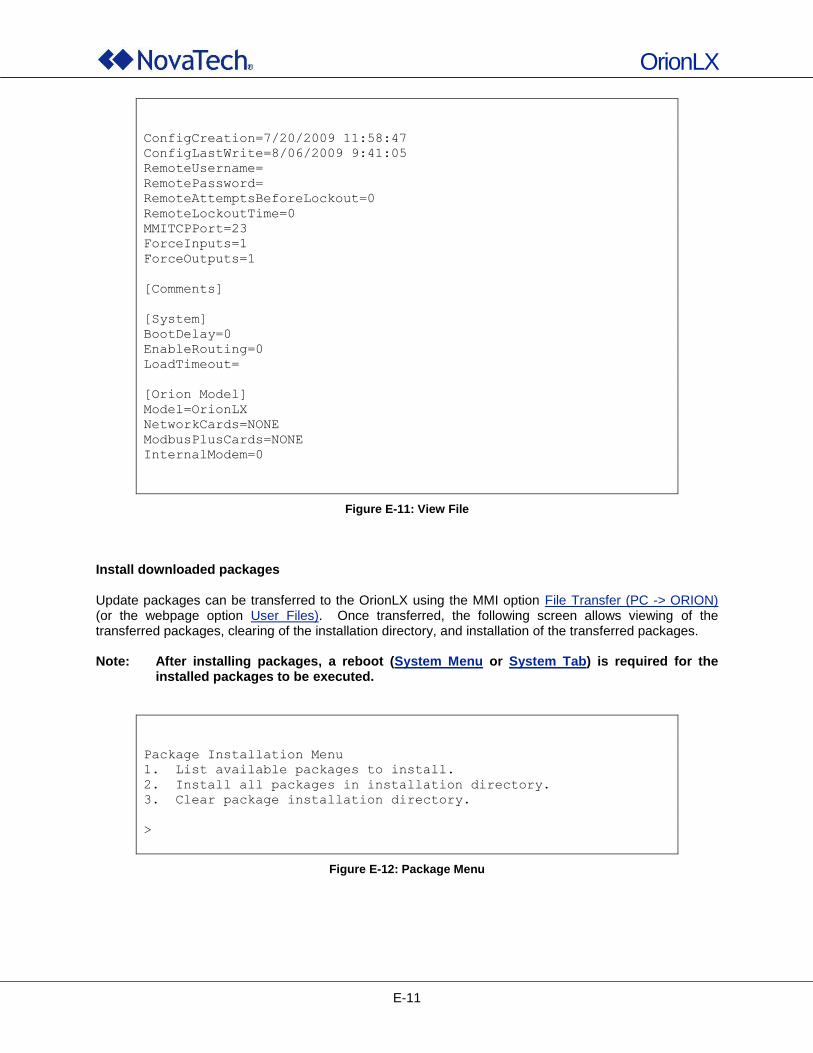
OrionLX
E-11
ConfigCreation=7/20/2009 11:58:47
ConfigLastWrite=8/06/2009 9:41:05
RemoteUsername=
RemotePassword=
RemoteAttemptsBeforeLockout=0
RemoteLockoutTime=0
MMITCPPort=23
ForceInputs=1
ForceOutputs=1
[Comments]
[System]
BootDelay=0
EnableRouting=0
LoadTimeout=
[Orion Model]
Model=OrionLX
NetworkCards=NONE
ModbusPlusCards=NONE
InternalModem=0
Figure E-11: View File
Install downloaded packages Update packages can be transferred to the OrionLX using the MMI option File Transfer (PC -> ORION) (or the webpage option User Files). Once transferred, the following screen allows viewing of the transferred packages, clearing of the installation directory, and installation of the transferred packages. Note: After installing packages, a reboot (System Menu or System Tab) is required for the
installed packages to be executed.
Package Installation Menu
1. List available packages to install.
2. Install all packages in installation directory.
3. Clear package installation directory.
>
Figure E-12: Package Menu
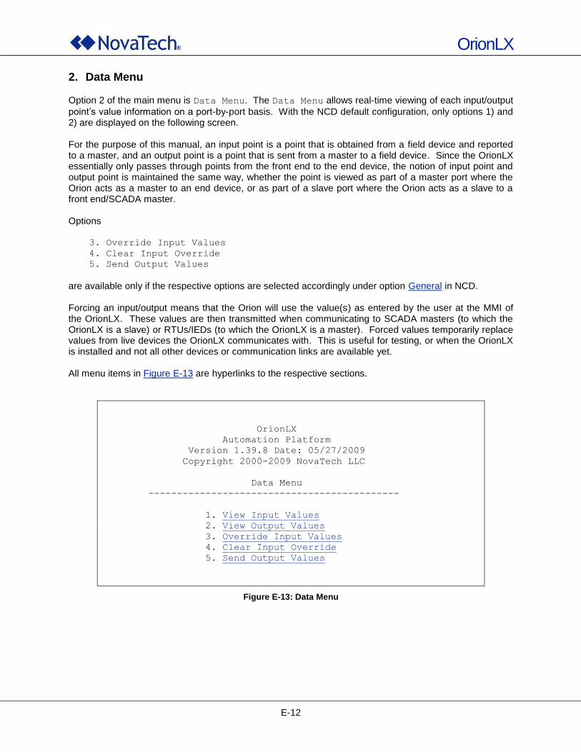
OrionLX
E-12
2. Data Menu
Option 2 of the main menu is Data Menu. The Data Menu allows real-time viewing of each input/output
point‟s value information on a port-by-port basis. With the NCD default configuration, only options 1) and 2) are displayed on the following screen. For the purpose of this manual, an input point is a point that is obtained from a field device and reported to a master, and an output point is a point that is sent from a master to a field device. Since the OrionLX essentially only passes through points from the front end to the end device, the notion of input point and output point is maintained the same way, whether the point is viewed as part of a master port where the Orion acts as a master to an end device, or as part of a slave port where the Orion acts as a slave to a front end/SCADA master. Options
3. Override Input Values
4. Clear Input Override
5. Send Output Values
are available only if the respective options are selected accordingly under option General in NCD. Forcing an input/output means that the Orion will use the value(s) as entered by the user at the MMI of the OrionLX. These values are then transmitted when communicating to SCADA masters (to which the OrionLX is a slave) or RTUs/IEDs (to which the OrionLX is a master). Forced values temporarily replace values from live devices the OrionLX communicates with. This is useful for testing, or when the OrionLX is installed and not all other devices or communication links are available yet. All menu items in Figure E-13 are hyperlinks to the respective sections.
OrionLX
Automation Platform
Version 1.39.8 Date: 05/27/2009
Copyright 2000-2009 NovaTech LLC
Data Menu
--------------------------------------------
1. View Input Values
2. View Output Values
3. Override Input Values
4. Clear Input Override
5. Send Output Values
Figure E-13: Data Menu
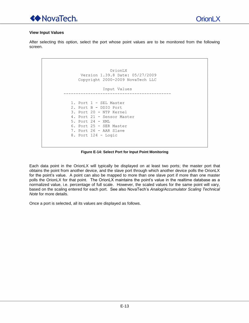
OrionLX
E-13
View Input Values After selecting this option, select the port whose point values are to be monitored from the following screen.
OrionLX
Version 1.39.8 Date: 05/27/2009
Copyright 2000-2009 NovaTech LLC
Input Values
--------------------------------------------
1. Port 1 - SEL Master
2. Port B - DDIO Port
3. Port 20 - NTP Kernel
4. Port 21 - Sensor Master
5. Port 24 - XML
6. Port 25 - SER Master
7. Port 26 - AAR Slave
8. Port 124 - Logic
Figure E-14: Select Port for Input Point Monitoring
Each data point in the OrionLX will typically be displayed on at least two ports; the master port that obtains the point from another device, and the slave port through which another device polls the OrionLX for the point‟s value. A point can also be mapped to more than one slave port if more than one master polls the OrionLX for that point. The OrionLX maintains the point‟s value in the realtime database as a normalized value, i.e. percentage of full scale. However, the scaled values for the same point will vary, based on the scaling entered for each port. See also NovaTech‟s Analog/Accumulator Scaling Technical Note for more details. Once a port is selected, all its values are displayed as follows.
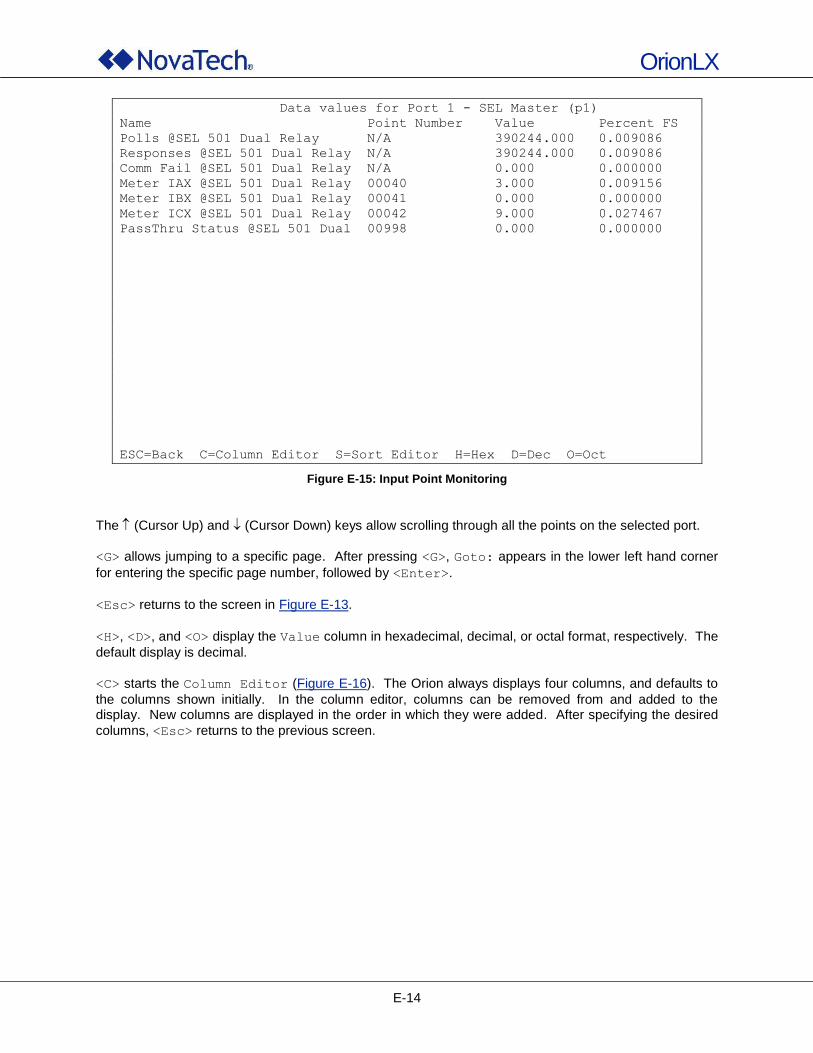
OrionLX
E-14
Data values for Port 1 - SEL Master (p1)
Name Point Number Value Percent FS
Polls @SEL 501 Dual Relay N/A 390244.000 0.009086
Responses @SEL 501 Dual Relay N/A 390244.000 0.009086
Comm Fail @SEL 501 Dual Relay N/A 0.000 0.000000
Meter IAX @SEL 501 Dual Relay 00040 3.000 0.009156
Meter IBX @SEL 501 Dual Relay 00041 0.000 0.000000
Meter ICX @SEL 501 Dual Relay 00042 9.000 0.027467
PassThru Status @SEL 501 Dual 00998 0.000 0.000000
ESC=Back C=Column Editor S=Sort Editor H=Hex D=Dec O=Oct
Figure E-15: Input Point Monitoring
The (Cursor Up) and (Cursor Down) keys allow scrolling through all the points on the selected port.
<G> allows jumping to a specific page. After pressing <G>, Goto: appears in the lower left hand corner
for entering the specific page number, followed by <Enter>.
<Esc> returns to the screen in Figure E-13.
<H>, <D>, and <O> display the Value column in hexadecimal, decimal, or octal format, respectively. The
default display is decimal.
<C> starts the Column Editor (Figure E-16). The Orion always displays four columns, and defaults to
the columns shown initially. In the column editor, columns can be removed from and added to the display. New columns are displayed in the order in which they were added. After specifying the desired
columns, <Esc> returns to the previous screen.
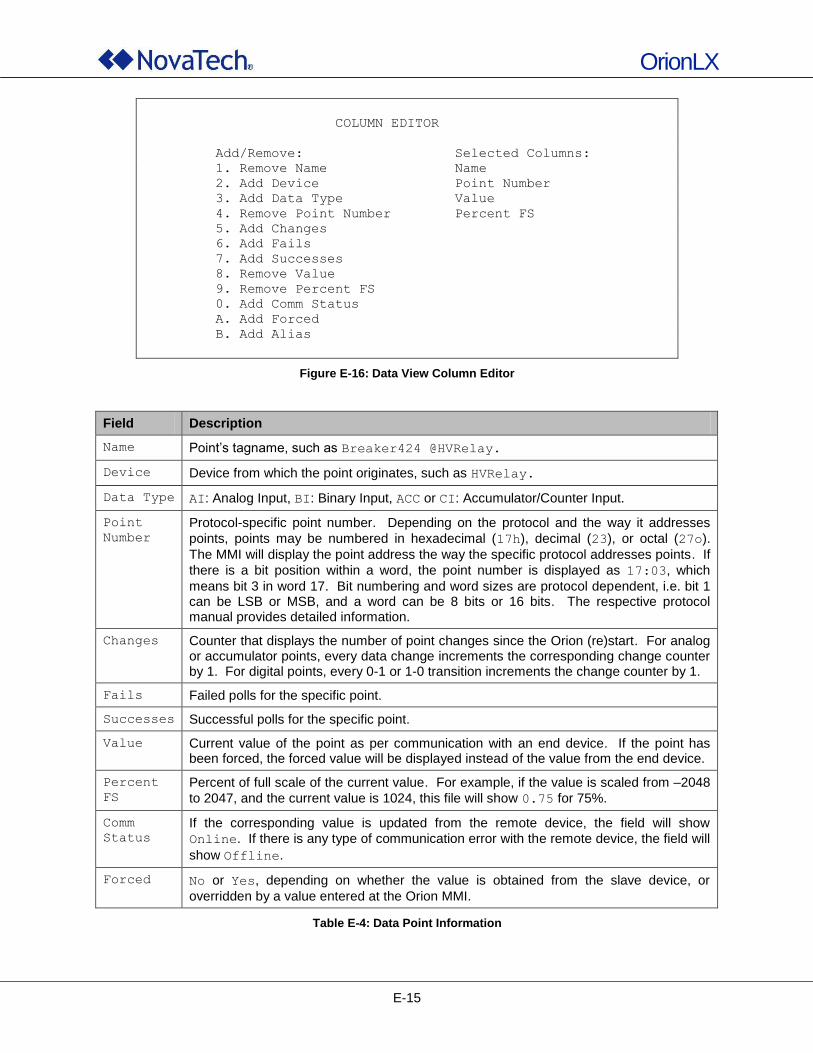
OrionLX
E-15
COLUMN EDITOR
Add/Remove: Selected Columns:
1. Remove Name Name
2. Add Device Point Number
3. Add Data Type Value
4. Remove Point Number Percent FS
5. Add Changes
6. Add Fails
7. Add Successes
8. Remove Value
9. Remove Percent FS
0. Add Comm Status
A. Add Forced
B. Add Alias
Figure E-16: Data View Column Editor
Field Description
Name Point‟s tagname, such as Breaker424 @HVRelay.
Device Device from which the point originates, such as HVRelay.
Data Type AI: Analog Input, BI: Binary Input, ACC or CI: Accumulator/Counter Input.
Point
Number
Protocol-specific point number. Depending on the protocol and the way it addresses
points, points may be numbered in hexadecimal (17h), decimal (23), or octal (27o).
The MMI will display the point address the way the specific protocol addresses points. If
there is a bit position within a word, the point number is displayed as 17:03, which
means bit 3 in word 17. Bit numbering and word sizes are protocol dependent, i.e. bit 1 can be LSB or MSB, and a word can be 8 bits or 16 bits. The respective protocol manual provides detailed information.
Changes Counter that displays the number of point changes since the Orion (re)start. For analog or accumulator points, every data change increments the corresponding change counter by 1. For digital points, every 0-1 or 1-0 transition increments the change counter by 1.
Fails Failed polls for the specific point.
Successes Successful polls for the specific point.
Value Current value of the point as per communication with an end device. If the point has been forced, the forced value will be displayed instead of the value from the end device.
Percent
FS
Percent of full scale of the current value. For example, if the value is scaled from –2048
to 2047, and the current value is 1024, this file will show 0.75 for 75%.
Comm
Status
If the corresponding value is updated from the remote device, the field will show
Online. If there is any type of communication error with the remote device, the field will
show Offline.
Forced No or Yes, depending on whether the value is obtained from the slave device, or
overridden by a value entered at the Orion MMI.
Table E-4: Data Point Information
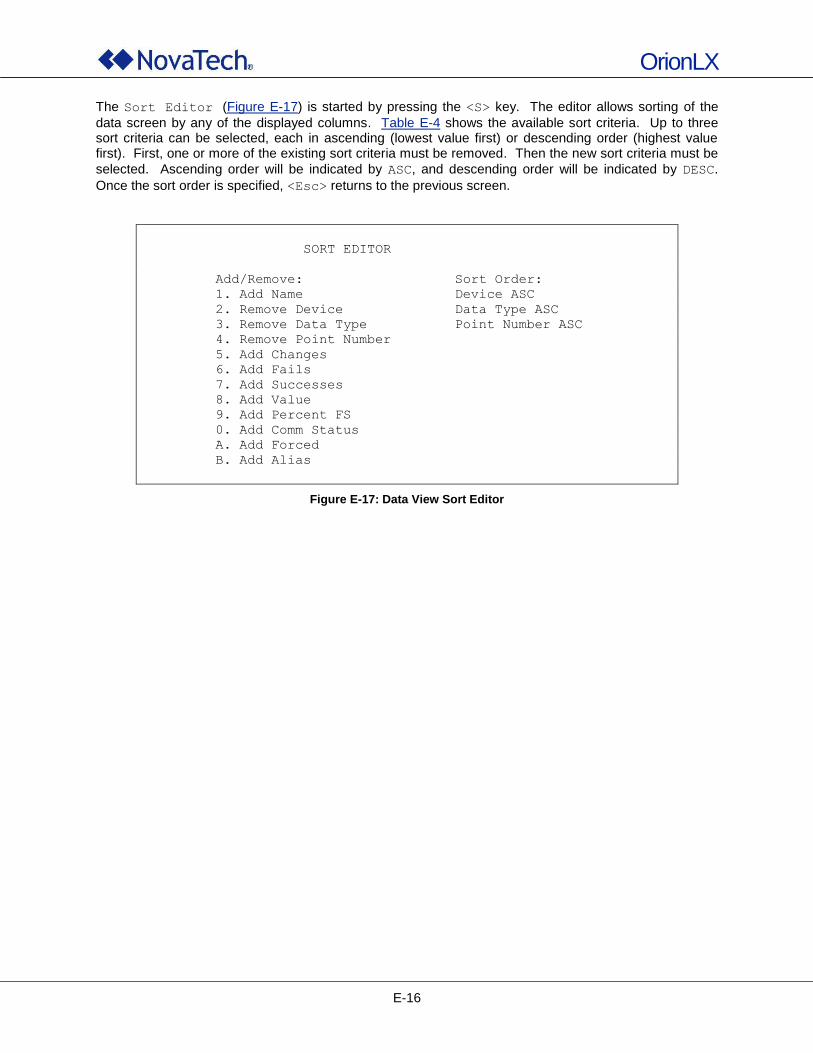
OrionLX
E-16
The Sort Editor (Figure E-17) is started by pressing the <S> key. The editor allows sorting of the
data screen by any of the displayed columns. Table E-4 shows the available sort criteria. Up to three sort criteria can be selected, each in ascending (lowest value first) or descending order (highest value first). First, one or more of the existing sort criteria must be removed. Then the new sort criteria must be
selected. Ascending order will be indicated by ASC, and descending order will be indicated by DESC.
Once the sort order is specified, <Esc> returns to the previous screen.
SORT EDITOR
Add/Remove: Sort Order:
1. Add Name Device ASC
2. Remove Device Data Type ASC
3. Remove Data Type Point Number ASC
4. Remove Point Number
5. Add Changes
6. Add Fails
7. Add Successes
8. Add Value
9. Add Percent FS
0. Add Comm Status
A. Add Forced
B. Add Alias
Figure E-17: Data View Sort Editor
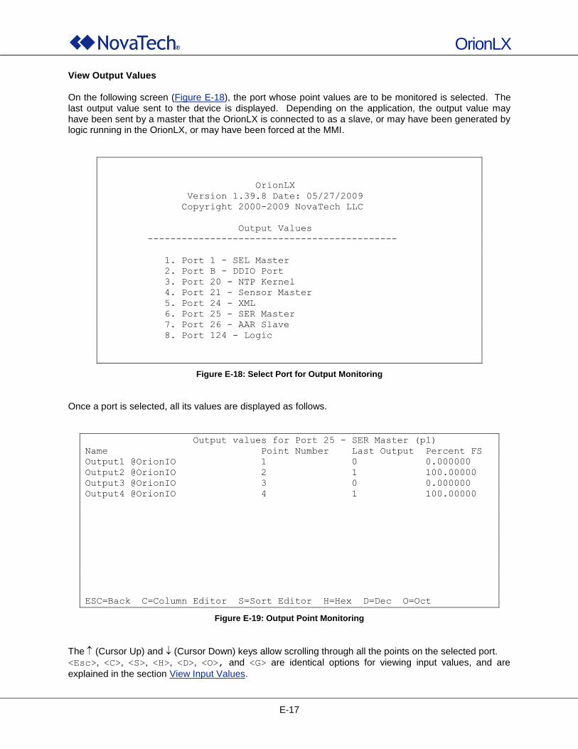
OrionLX
E-17
View Output Values On the following screen (Figure E-18), the port whose point values are to be monitored is selected. The last output value sent to the device is displayed. Depending on the application, the output value may have been sent by a master that the OrionLX is connected to as a slave, or may have been generated by logic running in the OrionLX, or may have been forced at the MMI.
OrionLX
Version 1.39.8 Date: 05/27/2009
Copyright 2000-2009 NovaTech LLC
Output Values
--------------------------------------------
1. Port 1 - SEL Master
2. Port B - DDIO Port
3. Port 20 - NTP Kernel
4. Port 21 - Sensor Master
5. Port 24 - XML
6. Port 25 - SER Master
7. Port 26 - AAR Slave
8. Port 124 - Logic
Figure E-18: Select Port for Output Monitoring
Once a port is selected, all its values are displayed as follows.
Output values for Port 25 - SER Master (p1)
Name Point Number Last Output Percent FS
Output1 @OrionIO 1 0 0.000000
Output2 @OrionIO 2 1 100.00000
Output3 @OrionIO 3 0 0.000000
Output4 @OrionIO 4 1 100.00000
ESC=Back C=Column Editor S=Sort Editor H=Hex D=Dec O=Oct
Figure E-19: Output Point Monitoring
The (Cursor Up) and (Cursor Down) keys allow scrolling through all the points on the selected port.
<Esc>, <C>, <S>, <H>, <D>, <O>, and <G> are identical options for viewing input values, and are
explained in the section View Input Values.
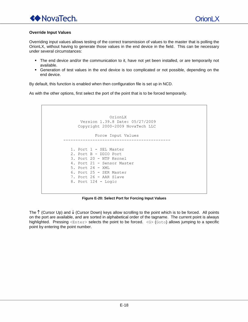
OrionLX
E-18
Override Input Values Overriding input values allows testing of the correct transmission of values to the master that is polling the OrionLX, without having to generate those values in the end device in the field. This can be necessary under several circumstances: The end device and/or the communication to it, have not yet been installed, or are temporarily not
available. Generation of test values in the end device is too complicated or not possible, depending on the
end device. By default, this function is enabled when then configuration file is set up in NCD. As with the other options, first select the port of the point that is to be forced temporarily.
OrionLX
Version 1.39.8 Date: 05/27/2009
Copyright 2000-2009 NovaTech LLC
Force Input Values
--------------------------------------------
1. Port 1 - SEL Master
2. Port B - DDIO Port
3. Port 20 - NTP Kernel
4. Port 21 - Sensor Master
5. Port 24 - XML
6. Port 25 - SER Master
7. Port 26 - AAR Slave
8. Port 124 - Logic
Figure E-20: Select Port for Forcing Input Values
The (Cursor Up) and (Cursor Down) keys allow scrolling to the point which is to be forced. All points on the port are available, and are sorted in alphabetical order of the tagname. The current point is always
highlighted. Pressing <Enter> selects the point to be forced. <G> (Goto) allows jumping to a specific
point by entering the point number.
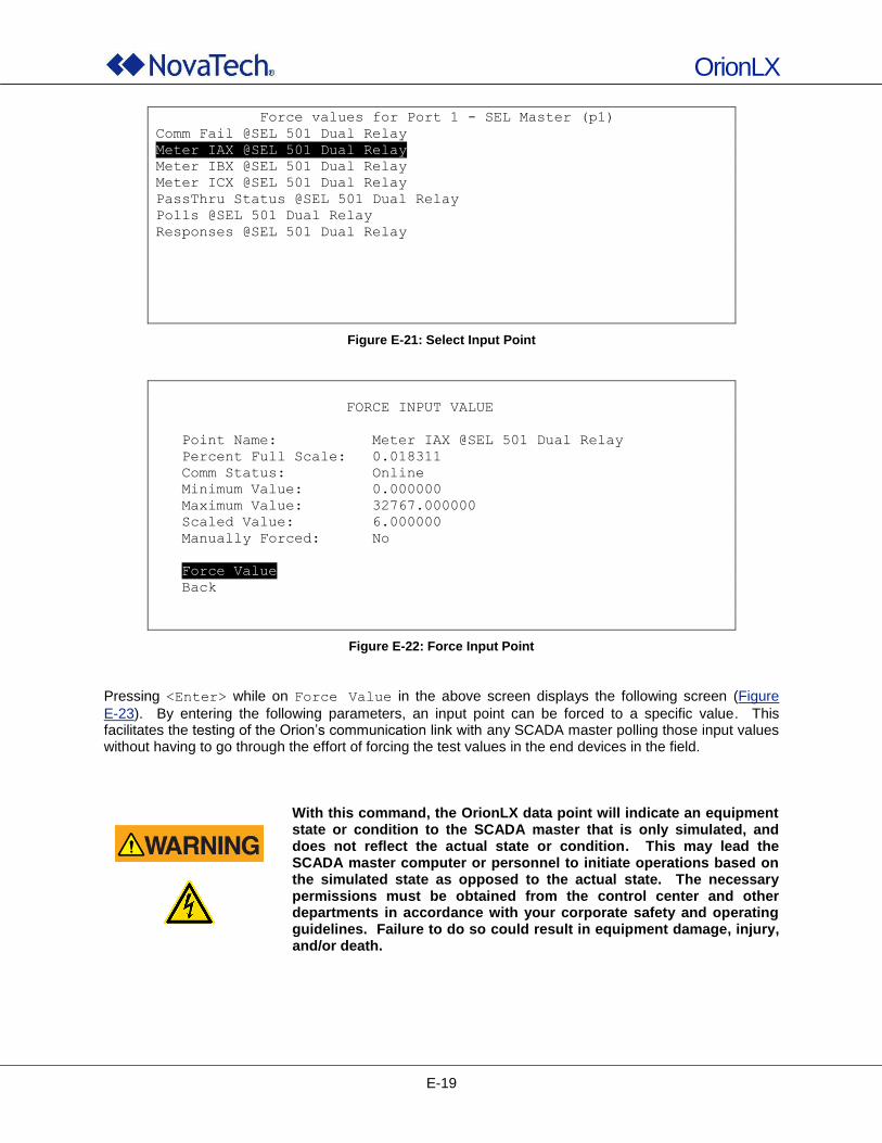
OrionLX
E-19
Force values for Port 1 - SEL Master (p1)
Comm Fail @SEL 501 Dual Relay
Meter IAX @SEL 501 Dual Relay
Meter IBX @SEL 501 Dual Relay
Meter ICX @SEL 501 Dual Relay
PassThru Status @SEL 501 Dual Relay
Polls @SEL 501 Dual Relay
Responses @SEL 501 Dual Relay
Figure E-21: Select Input Point
FORCE INPUT VALUE
Point Name: Meter IAX @SEL 501 Dual Relay
Percent Full Scale: 0.018311
Comm Status: Online
Minimum Value: 0.000000
Maximum Value: 32767.000000
Scaled Value: 6.000000
Manually Forced: No
Force Value
Back
Figure E-22: Force Input Point
Pressing <Enter> while on Force Value in the above screen displays the following screen (Figure
E-23). By entering the following parameters, an input point can be forced to a specific value. This facilitates the testing of the Orion‟s communication link with any SCADA master polling those input values without having to go through the effort of forcing the test values in the end devices in the field.
With this command, the OrionLX data point will indicate an equipment state or condition to the SCADA master that is only simulated, and does not reflect the actual state or condition. This may lead the SCADA master computer or personnel to initiate operations based on the simulated state as opposed to the actual state. The necessary permissions must be obtained from the control center and other departments in accordance with your corporate safety and operating guidelines. Failure to do so could result in equipment damage, injury, and/or death.
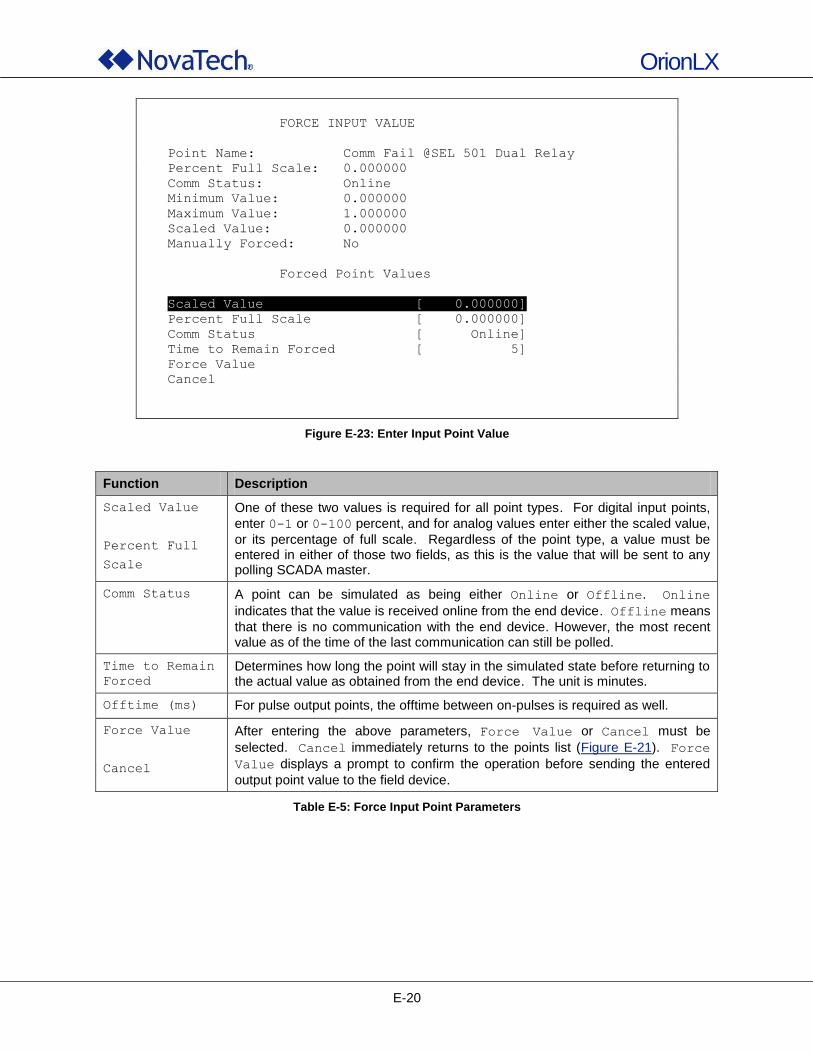
OrionLX
E-20
FORCE INPUT VALUE
Point Name: Comm Fail @SEL 501 Dual Relay
Percent Full Scale: 0.000000
Comm Status: Online
Minimum Value: 0.000000
Maximum Value: 1.000000
Scaled Value: 0.000000
Manually Forced: No
Forced Point Values
Scaled Value [ 0.000000]
Percent Full Scale [ 0.000000]
Comm Status [ Online]
Time to Remain Forced [ 5]
Force Value
Cancel
Figure E-23: Enter Input Point Value
Function Description
Scaled Value
Percent Full
Scale
One of these two values is required for all point types. For digital input points,
enter 0-1 or 0-100 percent, and for analog values enter either the scaled value,
or its percentage of full scale. Regardless of the point type, a value must be entered in either of those two fields, as this is the value that will be sent to any polling SCADA master.
Comm Status A point can be simulated as being either Online or Offline. Online
indicates that the value is received online from the end device. Offline means
that there is no communication with the end device. However, the most recent value as of the time of the last communication can still be polled.
Time to Remain
Forced
Determines how long the point will stay in the simulated state before returning to the actual value as obtained from the end device. The unit is minutes.
Offtime (ms) For pulse output points, the offtime between on-pulses is required as well.
Force Value
Cancel
After entering the above parameters, Force Value or Cancel must be
selected. Cancel immediately returns to the points list (Figure E-21). Force
Value displays a prompt to confirm the operation before sending the entered
output point value to the field device.
Table E-5: Force Input Point Parameters

OrionLX
E-21
FORCE INPUT VALUE
Point Name: Meter IAX @SEL 501 Dual Relay
Percent Full Scale: 0.024415
Comm Status: Online
Minimum Value: 0.000000
Maximum Value: 32767.000000
Scaled Value: 8.000000
Manually Forced: Yes
Remove Forced Value
Back
Figure E-24: Remove Forced Input Value
Clear Input Override With this option, forced inputs can be cleared. This means that all forced input values are removed, and that the realtime values from the field devices are used and transmitted to the master station again.
Are you sure that you want clear the override flag
for all input values? This will cause all forced
inputs to change value on the next scan.
(Y/N)
Figure E-25: Clear Input Override
With this command, multiple value and state changes may be reported to the SCADA master. All involved personnel must be informed of this step in order to avoid wrong responses to the realtime data reported to the SCADA master. Failure to do so could result in equipment damage, injury, and/or death.
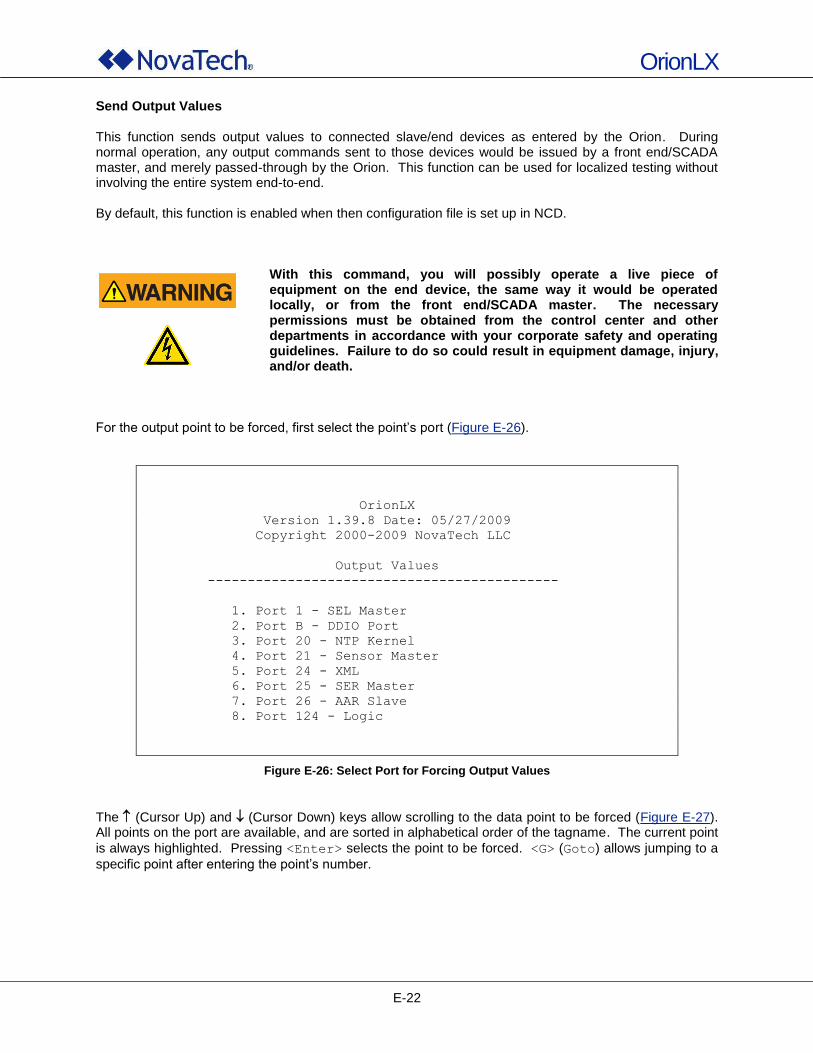
OrionLX
E-22
Send Output Values This function sends output values to connected slave/end devices as entered by the Orion. During normal operation, any output commands sent to those devices would be issued by a front end/SCADA master, and merely passed-through by the Orion. This function can be used for localized testing without involving the entire system end-to-end. By default, this function is enabled when then configuration file is set up in NCD.
With this command, you will possibly operate a live piece of equipment on the end device, the same way it would be operated locally, or from the front end/SCADA master. The necessary permissions must be obtained from the control center and other departments in accordance with your corporate safety and operating guidelines. Failure to do so could result in equipment damage, injury, and/or death.
For the output point to be forced, first select the point‟s port (Figure E-26).
OrionLX
Version 1.39.8 Date: 05/27/2009
Copyright 2000-2009 NovaTech LLC
Output Values
--------------------------------------------
1. Port 1 - SEL Master
2. Port B - DDIO Port
3. Port 20 - NTP Kernel
4. Port 21 - Sensor Master
5. Port 24 - XML
6. Port 25 - SER Master
7. Port 26 - AAR Slave
8. Port 124 - Logic
Figure E-26: Select Port for Forcing Output Values
The (Cursor Up) and (Cursor Down) keys allow scrolling to the data point to be forced (Figure E-27). All points on the port are available, and are sorted in alphabetical order of the tagname. The current point
is always highlighted. Pressing <Enter> selects the point to be forced. <G> (Goto) allows jumping to a
specific point after entering the point‟s number.
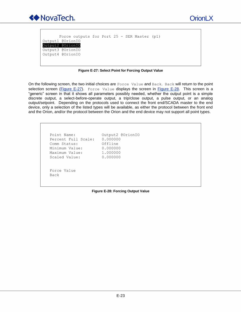
OrionLX
E-23
Force outputs for Port 25 - SER Master (p1)
Output1 @OrionIO
Output2 @OrionIO
Output3 @OrionIO
Output4 @OrionIO
Figure E-27: Select Point for Forcing Output Value
On the following screen, the two initial choices are Force Value and Back. Back will return to the point
selection screen (Figure E-27). Force Value displays the screen in Figure E-28. This screen is a
“generic” screen in that it shows all parameters possibly needed, whether the output point is a simple discrete output, a select-before-operate output, a trip/close output, a pulse output, or an analog output/setpoint. Depending on the protocols used to connect the front end/SCADA master to the end device, only a selection of the listed types will be available, as either the protocol between the front end and the Orion, and/or the protocol between the Orion and the end device may not support all point types.
Point Name: Output2 @OrionIO
Percent Full Scale: 0.000000
Comm Status: Offline
Minimum Value: 0.000000
Maximum Value: 1.000000
Scaled Value: 0.000000
Force Value
Back
Figure E-28: Forcing Output Value
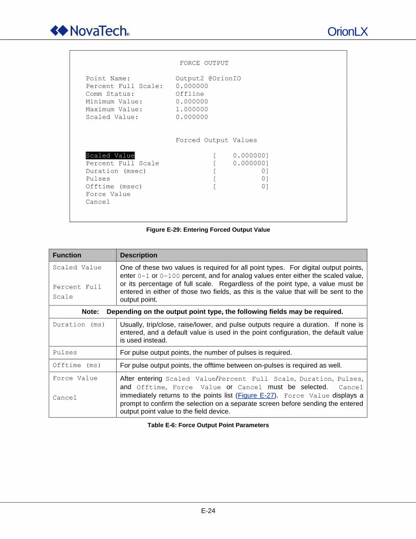
OrionLX
E-24
FORCE OUTPUT
Point Name: Output2 @OrionIO
Percent Full Scale: 0.000000
Comm Status: Offline
Minimum Value: 0.000000
Maximum Value: 1.000000
Scaled Value: 0.000000
Forced Output Values
Scaled Value [ 0.000000]
Percent Full Scale [ 0.000000]
Duration (msec) [ 0]
Pulses [ 0]
Offtime (msec) [ 0]
Force Value
Cancel
Figure E-29: Entering Forced Output Value
Function Description
Scaled Value
Percent Full
Scale
One of these two values is required for all point types. For digital output points,
enter 0-1 or 0-100 percent, and for analog values enter either the scaled value,
or its percentage of full scale. Regardless of the point type, a value must be entered in either of those two fields, as this is the value that will be sent to the output point.
Note: Depending on the output point type, the following fields may be required.
Duration (ms) Usually, trip/close, raise/lower, and pulse outputs require a duration. If none is entered, and a default value is used in the point configuration, the default value is used instead.
Pulses For pulse output points, the number of pulses is required.
Offtime (ms) For pulse output points, the offtime between on-pulses is required as well.
Force Value
Cancel
After entering Scaled Value/Percent Full Scale, Duration, Pulses,
and Offtime, Force Value or Cancel must be selected. Cancel
immediately returns to the points list (Figure E-27). Force Value displays a
prompt to confirm the selection on a separate screen before sending the entered output point value to the field device.
Table E-6: Force Output Point Parameters
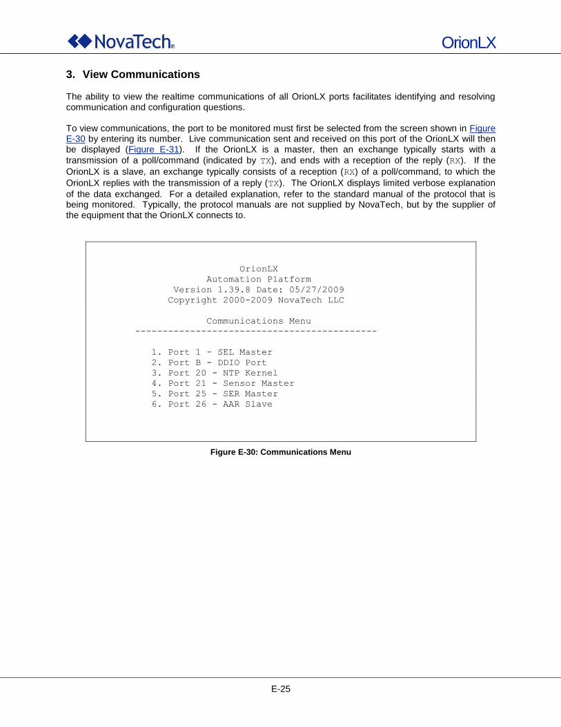
OrionLX
E-25
3. View Communications The ability to view the realtime communications of all OrionLX ports facilitates identifying and resolving communication and configuration questions. To view communications, the port to be monitored must first be selected from the screen shown in Figure E-30 by entering its number. Live communication sent and received on this port of the OrionLX will then be displayed (Figure E-31). If the OrionLX is a master, then an exchange typically starts with a
transmission of a poll/command (indicated by TX), and ends with a reception of the reply (RX). If the
OrionLX is a slave, an exchange typically consists of a reception (RX) of a poll/command, to which the
OrionLX replies with the transmission of a reply (TX). The OrionLX displays limited verbose explanation
of the data exchanged. For a detailed explanation, refer to the standard manual of the protocol that is being monitored. Typically, the protocol manuals are not supplied by NovaTech, but by the supplier of the equipment that the OrionLX connects to.
OrionLX
Automation Platform
Version 1.39.8 Date: 05/27/2009
Copyright 2000-2009 NovaTech LLC
Communications Menu
--------------------------------------------
1. Port 1 - SEL Master
2. Port B - DDIO Port
3. Port 20 - NTP Kernel
4. Port 21 - Sensor Master
5. Port 25 - SER Master
6. Port 26 - AAR Slave
Figure E-30: Communications Menu
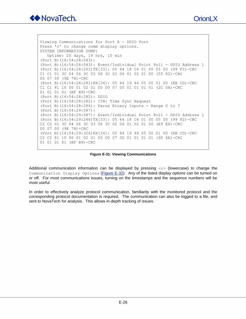
OrionLX
E-26
Viewing Communications for Port B - DDIO Port
Press 'c' to change comm display options.
SYSTEM INFORMATION DUMP:
Uptime: 20 days, 19 hrs, 10 min
(Port B)(16:54:28:043):
(Port B)(16:54:28:043): Event/Individual Point Poll - DDIO Address 1
(Port B)(16:54:28:203)TX[33]: 05 64 18 C4 01 00 05 00 (99 F2)-CRC
C1 C1 01 3C 04 06 3C 03 06 3C 02 06 01 02 01 00 (55 82)-CRC
00 07 00 (9E 78)-CRC
(Port B)(16:54:28:281)RX[34]: 05 64 19 44 05 00 01 00 (EB CD)-CRC
C1 C1 81 10 00 01 02 01 00 00 07 00 01 01 01 01 (2C 0A)-CRC
01 01 01 01 (BF B9)-CRC
(Port B)(16:54:28:282): DDIO
(Port B)(16:54:28:282): IIN: Time Sync Request
(Port B)(16:54:28:284): Parse Binary Inputs - Range 0 to 7
(Port B)(16:54:29:087):
(Port B)(16:54:29:087): Event/Individual Point Poll - DDIO Address 1
(Port B)(16:54:29:246)TX[33]: 05 64 18 C4 01 00 05 00 (99 F2)-CRC
C2 C2 01 3C 04 06 3C 03 06 3C 02 06 01 02 01 00 (E9 E6)-CRC
00 07 00 (9E 78)-CRC
(Port B)(16:54:29:326)RX[34]: 05 64 19 44 05 00 01 00 (EB CD)-CRC
C2 C2 81 10 00 01 02 01 00 00 07 00 01 01 01 01 (90 6E)-CRC
01 01 01 01 (BF B9)-CRC
Figure E-31: Viewing Communications
Additional communication information can be displayed by pressing <c> (lowercase) to change the
Communication Display Options (Figure E-32). Any of the listed display options can be turned on
or off. For most communications issues, turning on the timestamps and the sequence numbers will be most useful. In order to effectively analyze protocol communication, familiarity with the monitored protocol and the corresponding protocol documentation is required. The communication can also be logged to a file, and sent to NovaTech for analysis. This allows in-depth tracking of issues.
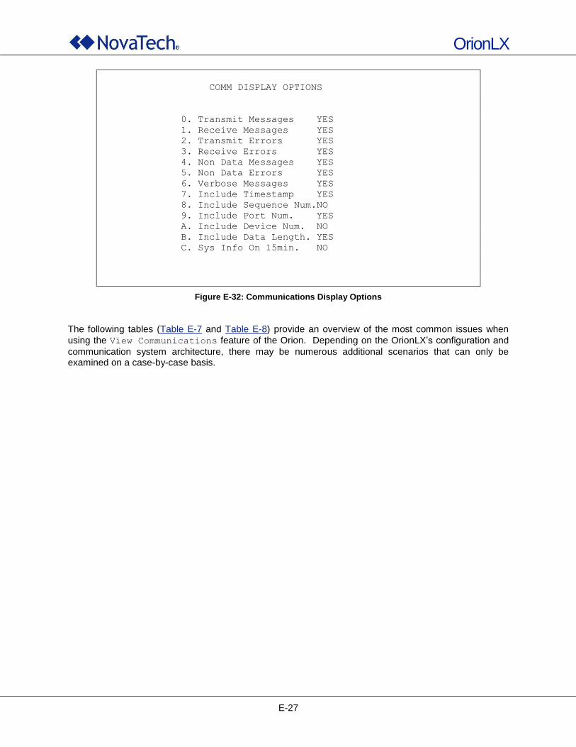
OrionLX
E-27
COMM DISPLAY OPTIONS
0. Transmit Messages YES
1. Receive Messages YES
2. Transmit Errors YES
3. Receive Errors YES
4. Non Data Messages YES
5. Non Data Errors YES
6. Verbose Messages YES
7. Include Timestamp YES
8. Include Sequence Num.NO
9. Include Port Num. YES
A. Include Device Num. NO
B. Include Data Length. YES
C. Sys Info On 15min. NO
Figure E-32: Communications Display Options
The following tables (Table E-7 and Table E-8) provide an overview of the most common issues when
using the View Communications feature of the Orion. Depending on the OrionLX‟s configuration and
communication system architecture, there may be numerous additional scenarios that can only be examined on a case-by-case basis.
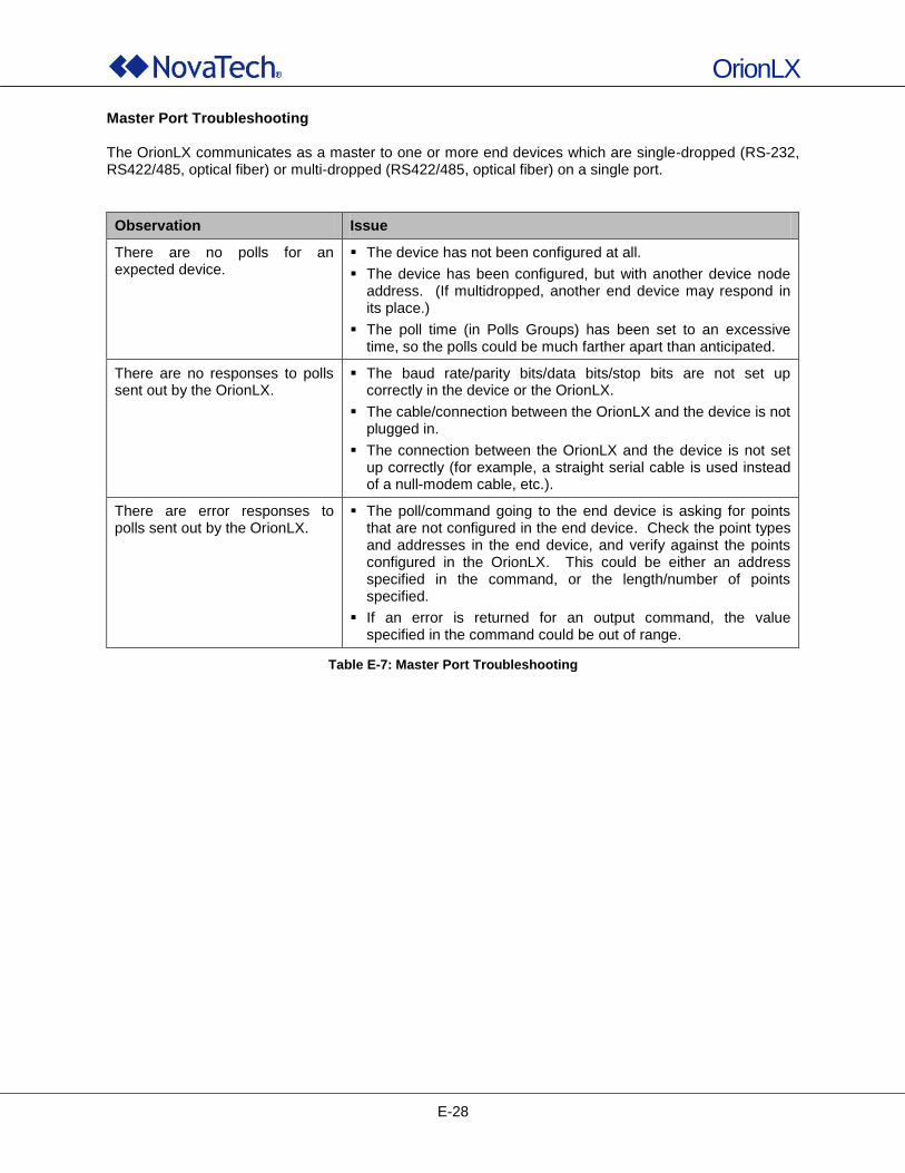
OrionLX
E-28
Master Port Troubleshooting The OrionLX communicates as a master to one or more end devices which are single-dropped (RS-232, RS422/485, optical fiber) or multi-dropped (RS422/485, optical fiber) on a single port.
Observation Issue
There are no polls for an expected device.
The device has not been configured at all.
The device has been configured, but with another device node address. (If multidropped, another end device may respond in its place.)
The poll time (in Polls Groups) has been set to an excessive time, so the polls could be much farther apart than anticipated.
There are no responses to polls sent out by the OrionLX.
The baud rate/parity bits/data bits/stop bits are not set up correctly in the device or the OrionLX.
The cable/connection between the OrionLX and the device is not plugged in.
The connection between the OrionLX and the device is not set up correctly (for example, a straight serial cable is used instead of a null-modem cable, etc.).
There are error responses to polls sent out by the OrionLX.
The poll/command going to the end device is asking for points that are not configured in the end device. Check the point types and addresses in the end device, and verify against the points configured in the OrionLX. This could be either an address specified in the command, or the length/number of points specified.
If an error is returned for an output command, the value specified in the command could be out of range.
Table E-7: Master Port Troubleshooting
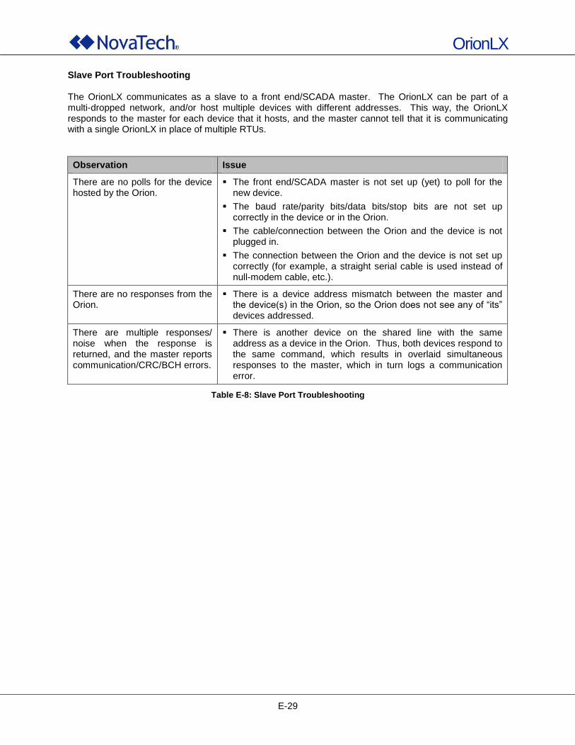
OrionLX
E-29
Slave Port Troubleshooting The OrionLX communicates as a slave to a front end/SCADA master. The OrionLX can be part of a multi-dropped network, and/or host multiple devices with different addresses. This way, the OrionLX responds to the master for each device that it hosts, and the master cannot tell that it is communicating with a single OrionLX in place of multiple RTUs.
Observation Issue
There are no polls for the device hosted by the Orion.
The front end/SCADA master is not set up (yet) to poll for the new device.
The baud rate/parity bits/data bits/stop bits are not set up correctly in the device or in the Orion.
The cable/connection between the Orion and the device is not plugged in.
The connection between the Orion and the device is not set up correctly (for example, a straight serial cable is used instead of null-modem cable, etc.).
There are no responses from the Orion.
There is a device address mismatch between the master and the device(s) in the Orion, so the Orion does not see any of “its” devices addressed.
There are multiple responses/ noise when the response is returned, and the master reports communication/CRC/BCH errors.
There is another device on the shared line with the same address as a device in the Orion. Thus, both devices respond to the same command, which results in overlaid simultaneous responses to the master, which in turn logs a communication error.
Table E-8: Slave Port Troubleshooting
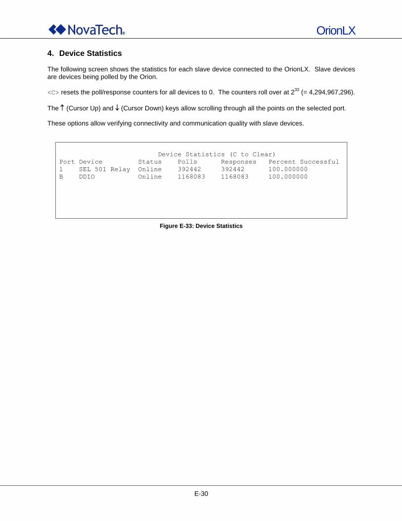
OrionLX
E-30
4. Device Statistics The following screen shows the statistics for each slave device connected to the OrionLX. Slave devices are devices being polled by the Orion.
<C> resets the poll/response counters for all devices to 0. The counters roll over at 232
(= 4,294,967,296).
The (Cursor Up) and (Cursor Down) keys allow scrolling through all the points on the selected port. These options allow verifying connectivity and communication quality with slave devices.
Device Statistics (C to Clear)
Port Device Status Polls Responses Percent Successful
1 SEL 501 Relay Online 392442 392442 100.000000
B DDIO Online 1168083 1168083 100.000000
Figure E-33: Device Statistics
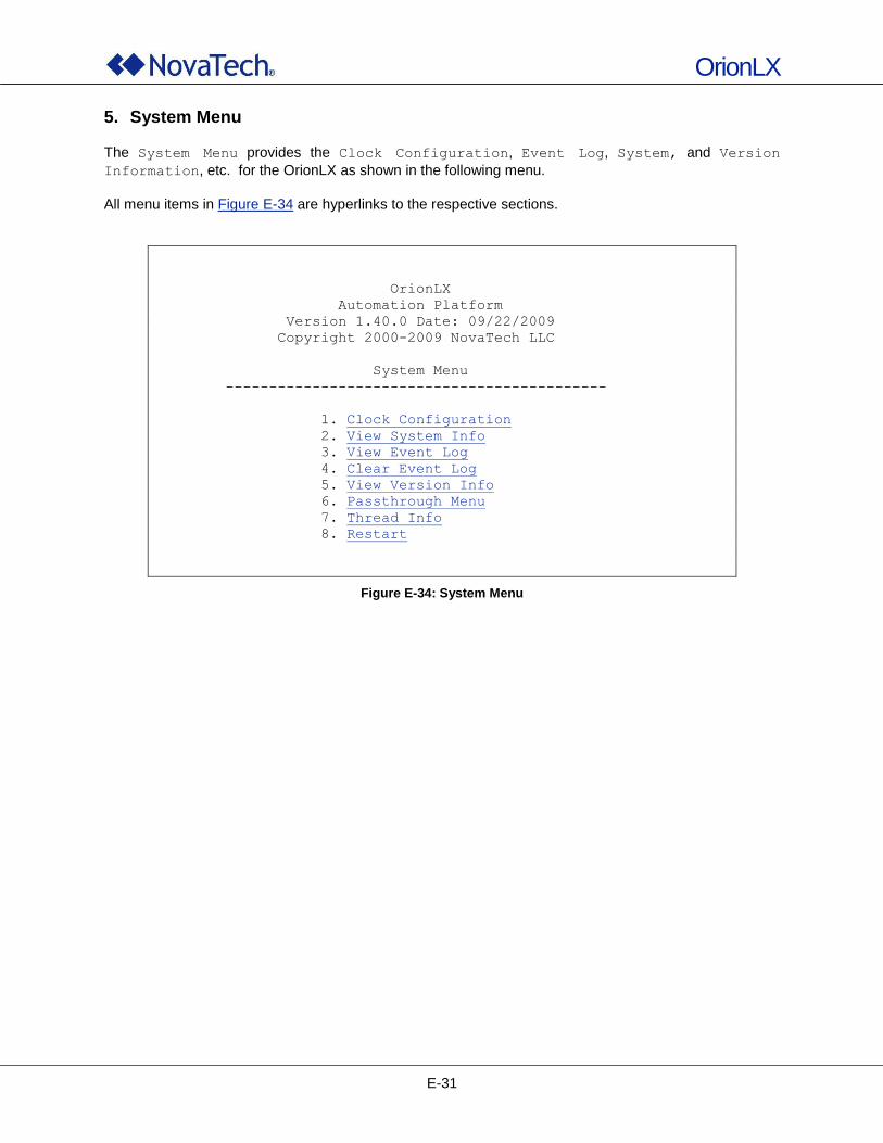
OrionLX
E-31
5. System Menu
The System Menu provides the Clock Configuration, Event Log, System, and Version
Information, etc. for the OrionLX as shown in the following menu.
All menu items in Figure E-34 are hyperlinks to the respective sections.
OrionLX
Automation Platform
Version 1.40.0 Date: 09/22/2009
Copyright 2000-2009 NovaTech LLC
System Menu
--------------------------------------------
1. Clock Configuration
2. View System Info
3. View Event Log
4. Clear Event Log
5. View Version Info
6. Passthrough Menu
7. Thread Info
8. Restart
Figure E-34: System Menu
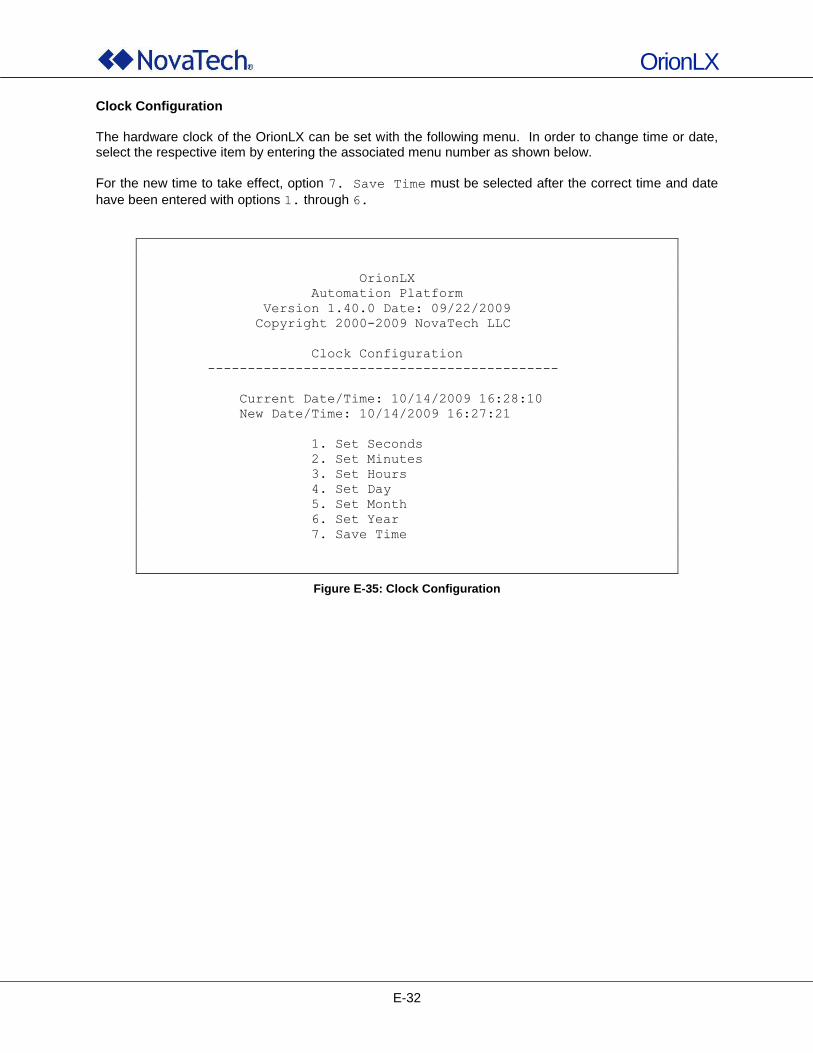
OrionLX
E-32
Clock Configuration The hardware clock of the OrionLX can be set with the following menu. In order to change time or date, select the respective item by entering the associated menu number as shown below.
For the new time to take effect, option 7. Save Time must be selected after the correct time and date
have been entered with options 1. through 6.
OrionLX
Automation Platform
Version 1.40.0 Date: 09/22/2009
Copyright 2000-2009 NovaTech LLC
Clock Configuration
--------------------------------------------
Current Date/Time: 10/14/2009 16:28:10
New Date/Time: 10/14/2009 16:27:21
1. Set Seconds
2. Set Minutes
3. Set Hours
4. Set Day
5. Set Month
6. Set Year
7. Save Time
Figure E-35: Clock Configuration
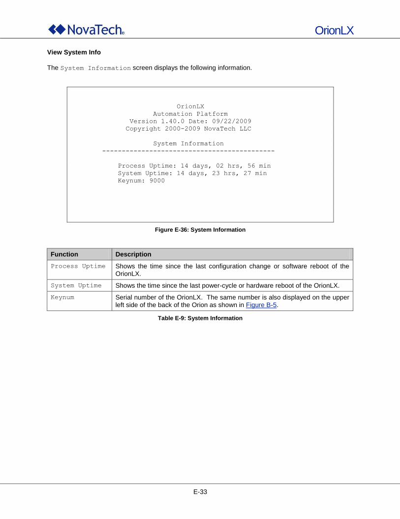
OrionLX
E-33
View System Info
The System Information screen displays the following information.
OrionLX
Automation Platform
Version 1.40.0 Date: 09/22/2009
Copyright 2000-2009 NovaTech LLC
System Information
--------------------------------------------
Process Uptime: 14 days, 02 hrs, 56 min
System Uptime: 14 days, 23 hrs, 27 min
Keynum: 9000
Figure E-36: System Information
Function Description
Process Uptime Shows the time since the last configuration change or software reboot of the OrionLX.
System Uptime Shows the time since the last power-cycle or hardware reboot of the OrionLX.
Keynum Serial number of the OrionLX. The same number is also displayed on the upper left side of the back of the Orion as shown in Figure B-5.
Table E-9: System Information
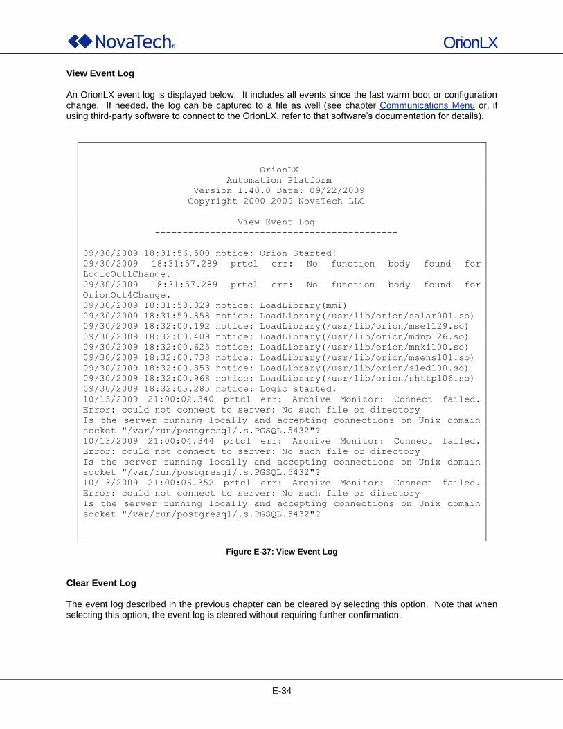
OrionLX
E-34
View Event Log An OrionLX event log is displayed below. It includes all events since the last warm boot or configuration change. If needed, the log can be captured to a file as well (see chapter Communications Menu or, if using third-party software to connect to the OrionLX, refer to that software‟s documentation for details).
OrionLX
Automation Platform
Version 1.40.0 Date: 09/22/2009
Copyright 2000-2009 NovaTech LLC
View Event Log
--------------------------------------------
09/30/2009 18:31:56.500 notice: Orion Started!
09/30/2009 18:31:57.289 prtcl err: No function body found for
LogicOut1Change.
09/30/2009 18:31:57.289 prtcl err: No function body found for
OrionOut4Change.
09/30/2009 18:31:58.329 notice: LoadLibrary(mmi)
09/30/2009 18:31:59.858 notice: LoadLibrary(/usr/lib/orion/salar001.so)
09/30/2009 18:32:00.192 notice: LoadLibrary(/usr/lib/orion/msel129.so)
09/30/2009 18:32:00.409 notice: LoadLibrary(/usr/lib/orion/mdnp126.so)
09/30/2009 18:32:00.625 notice: LoadLibrary(/usr/lib/orion/mnki100.so)
09/30/2009 18:32:00.738 notice: LoadLibrary(/usr/lib/orion/msens101.so)
09/30/2009 18:32:00.853 notice: LoadLibrary(/usr/lib/orion/sled100.so)
09/30/2009 18:32:00.968 notice: LoadLibrary(/usr/lib/orion/shttp106.so)
09/30/2009 18:32:05.285 notice: Logic started.
10/13/2009 21:00:02.340 prtcl err: Archive Monitor: Connect failed.
Error: could not connect to server: No such file or directory
Is the server running locally and accepting connections on Unix domain
socket "/var/run/postgresql/.s.PGSQL.5432"?
10/13/2009 21:00:04.344 prtcl err: Archive Monitor: Connect failed.
Error: could not connect to server: No such file or directory
Is the server running locally and accepting connections on Unix domain
socket "/var/run/postgresql/.s.PGSQL.5432"?
10/13/2009 21:00:06.352 prtcl err: Archive Monitor: Connect failed.
Error: could not connect to server: No such file or directory
Is the server running locally and accepting connections on Unix domain
socket "/var/run/postgresql/.s.PGSQL.5432"?
Figure E-37: View Event Log
Clear Event Log The event log described in the previous chapter can be cleared by selecting this option. Note that when selecting this option, the event log is cleared without requiring further confirmation.
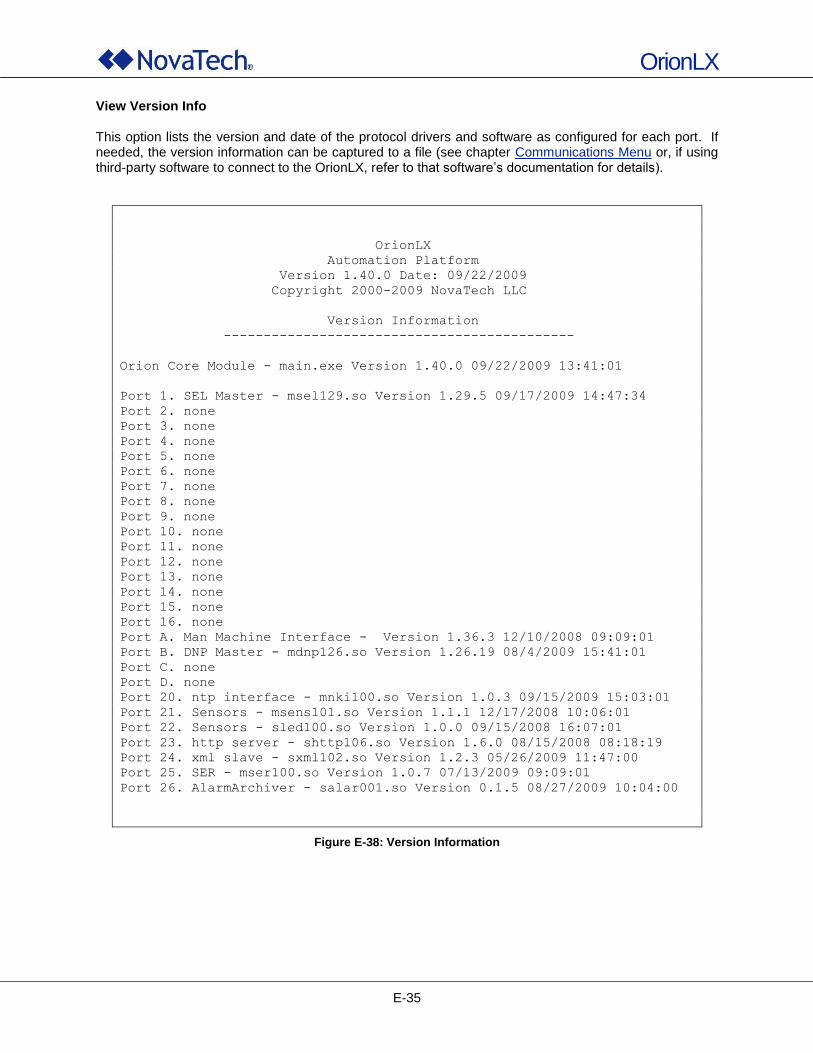
OrionLX
E-35
View Version Info This option lists the version and date of the protocol drivers and software as configured for each port. If needed, the version information can be captured to a file (see chapter Communications Menu or, if using third-party software to connect to the OrionLX, refer to that software‟s documentation for details).
OrionLX
Automation Platform
Version 1.40.0 Date: 09/22/2009
Copyright 2000-2009 NovaTech LLC
Version Information
--------------------------------------------
Orion Core Module - main.exe Version 1.40.0 09/22/2009 13:41:01
Port 1. SEL Master - msel129.so Version 1.29.5 09/17/2009 14:47:34
Port 2. none
Port 3. none
Port 4. none
Port 5. none
Port 6. none
Port 7. none
Port 8. none
Port 9. none
Port 10. none
Port 11. none
Port 12. none
Port 13. none
Port 14. none
Port 15. none
Port 16. none
Port A. Man Machine Interface - Version 1.36.3 12/10/2008 09:09:01
Port B. DNP Master - mdnp126.so Version 1.26.19 08/4/2009 15:41:01
Port C. none
Port D. none
Port 20. ntp interface - mnki100.so Version 1.0.3 09/15/2009 15:03:01
Port 21. Sensors - msens101.so Version 1.1.1 12/17/2008 10:06:01
Port 22. Sensors - sled100.so Version 1.0.0 09/15/2008 16:07:01
Port 23. http server - shttp106.so Version 1.6.0 08/15/2008 08:18:19
Port 24. xml slave - sxml102.so Version 1.2.3 05/26/2009 11:47:00
Port 25. SER - mser100.so Version 1.0.7 07/13/2009 09:09:01
Port 26. AlarmArchiver - salar001.so Version 0.1.5 08/27/2009 10:04:00
Figure E-38: Version Information
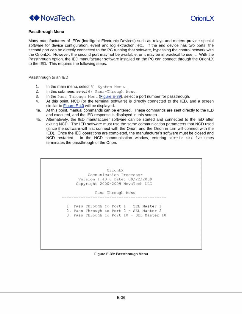
OrionLX
E-36
Passthrough Menu Many manufacturers of IEDs (Intelligent Electronic Devices) such as relays and meters provide special software for device configuration, event and log extraction, etc. If the end device has two ports, the second port can be directly connected to the PC running that software, bypassing the control network with the OrionLX. However, the second port may not be available, or it may be impractical to use it. With the Passthrough option, the IED manufacturer software installed on the PC can connect through the OrionLX to the IED. This requires the following steps. Passthrough to an IED
1. In the main menu, select 5) System Menu.
2. In this submenu, select 6) Pass-Through Menu.
3. In the Pass Through Menu (Figure E-39), select a port number for passthrough.
4. At this point, NCD (or the terminal software) is directly connected to the IED, and a screen similar to Figure E-40 will be displayed.
4a. At this point, manual commands can be entered. These commands are sent directly to the IED and executed, and the IED response is displayed in this screen.
4b. Alternatively, the IED manufacturer software can be started and connected to the IED after exiting NCD. The IED software must use the same communication parameters that NCD used (since the software will first connect with the Orion, and the Orion in turn will connect with the IED). Once the IED operations are completed, the manufacturer‟s software must be closed and
NCD restarted. In the NCD communication window, entering <Ctrl>-<X> five times
terminates the passthrough of the Orion.
OrionLX
Communication Processor
Version 1.40.0 Date: 09/22/2009
Copyright 2000-2009 NovaTech LLC
Pass Through Menu
--------------------------------------------
1. Pass Through to Port 1 - SEL Master 1
2. Pass Through to Port 2 - SEL Master 2
3. Pass Through to Port 10 - SEL Master 10
Figure E-39: Passthrough Menu
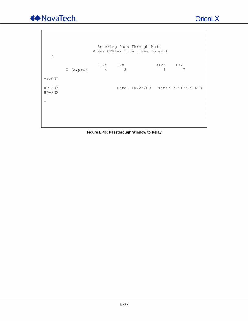
OrionLX
E-37
Entering Pass Through Mode
Press CTRL-X five times to exit
2
3I2X IRX 3I2Y IRY
I (A,pri) 4 3 8 7
=>>QUI
HP-233 Date: 10/26/09 Time: 22:17:09.603
HP-232
=
Figure E-40: Passthrough Window to Relay
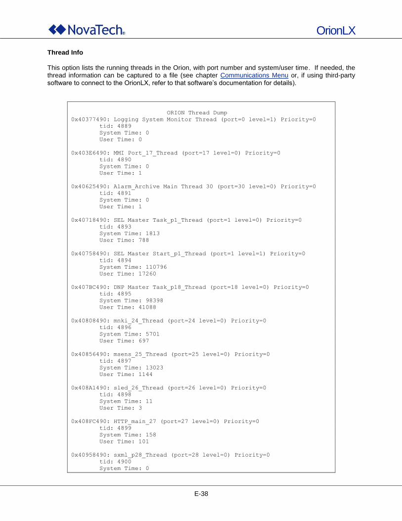
OrionLX
E-38
Thread Info This option lists the running threads in the Orion, with port number and system/user time. If needed, the thread information can be captured to a file (see chapter Communications Menu or, if using third-party software to connect to the OrionLX, refer to that software‟s documentation for details).
ORION Thread Dump
0x40377490: Logging System Monitor Thread (port=0 level=1) Priority=0
tid: 4889
System Time: 0
User Time: 0
0x403E6490: MMI Port_17_Thread (port=17 level=0) Priority=0
tid: 4890
System Time: 0
User Time: 1
0x40625490: Alarm_Archive Main Thread 30 (port=30 level=0) Priority=0
tid: 4891
System Time: 0
User Time: 1
0x40718490: SEL Master Task_p1_Thread (port=1 level=0) Priority=0
tid: 4893
System Time: 1813
User Time: 788
0x40758490: SEL Master Start_p1_Thread (port=1 level=1) Priority=0
tid: 4894
System Time: 110796
User Time: 17260
0x407BC490: DNP Master Task_p18_Thread (port=18 level=0) Priority=0
tid: 4895
System Time: 98398
User Time: 41088
0x40808490: mnki_24_Thread (port=24 level=0) Priority=0
tid: 4896
System Time: 5701
User Time: 697
0x40856490: msens_25_Thread (port=25 level=0) Priority=0
tid: 4897
System Time: 13023
User Time: 1144
0x408A1490: sled_26_Thread (port=26 level=0) Priority=0
tid: 4898
System Time: 11
User Time: 3
0x408FC490: HTTP_main_27 (port=27 level=0) Priority=0
tid: 4899
System Time: 158
User Time: 101
0x40958490: sxml_p28_Thread (port=28 level=0) Priority=0
tid: 4900
System Time: 0
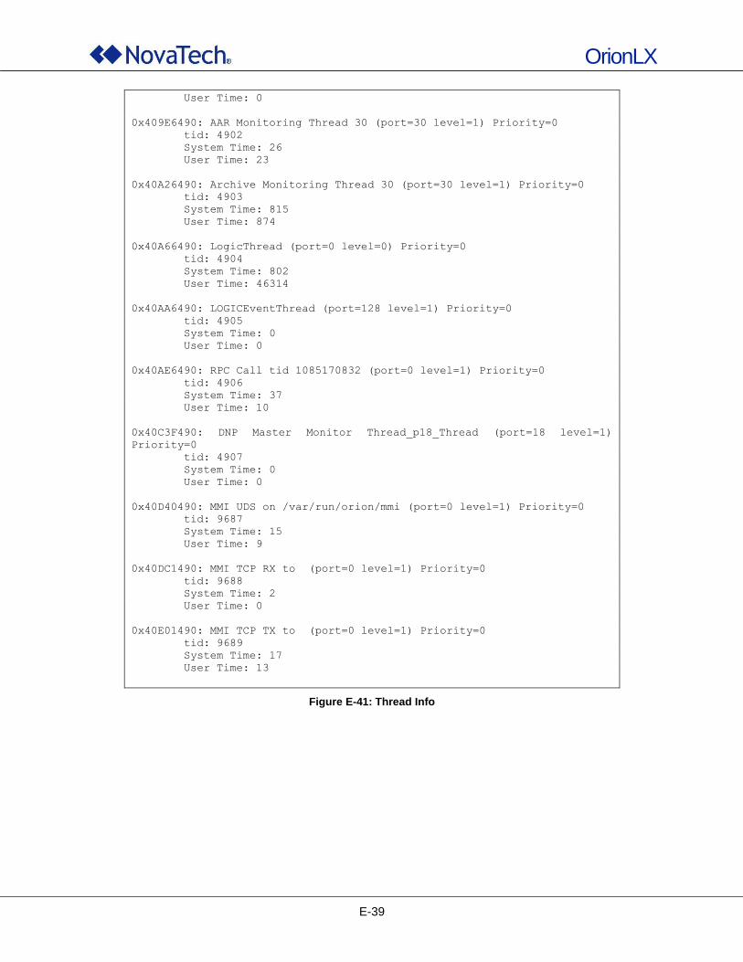
OrionLX
E-39
User Time: 0
0x409E6490: AAR Monitoring Thread 30 (port=30 level=1) Priority=0
tid: 4902
System Time: 26
User Time: 23
0x40A26490: Archive Monitoring Thread 30 (port=30 level=1) Priority=0
tid: 4903
System Time: 815
User Time: 874
0x40A66490: LogicThread (port=0 level=0) Priority=0
tid: 4904
System Time: 802
User Time: 46314
0x40AA6490: LOGICEventThread (port=128 level=1) Priority=0
tid: 4905
System Time: 0
User Time: 0
0x40AE6490: RPC Call tid 1085170832 (port=0 level=1) Priority=0
tid: 4906
System Time: 37
User Time: 10
0x40C3F490: DNP Master Monitor Thread_p18_Thread (port=18 level=1)
Priority=0
tid: 4907
System Time: 0
User Time: 0
0x40D40490: MMI UDS on /var/run/orion/mmi (port=0 level=1) Priority=0
tid: 9687
System Time: 15
User Time: 9
0x40DC1490: MMI TCP RX to (port=0 level=1) Priority=0
tid: 9688
System Time: 2
User Time: 0
0x40E01490: MMI TCP TX to (port=0 level=1) Priority=0
tid: 9689
System Time: 17
User Time: 13
Figure E-41: Thread Info
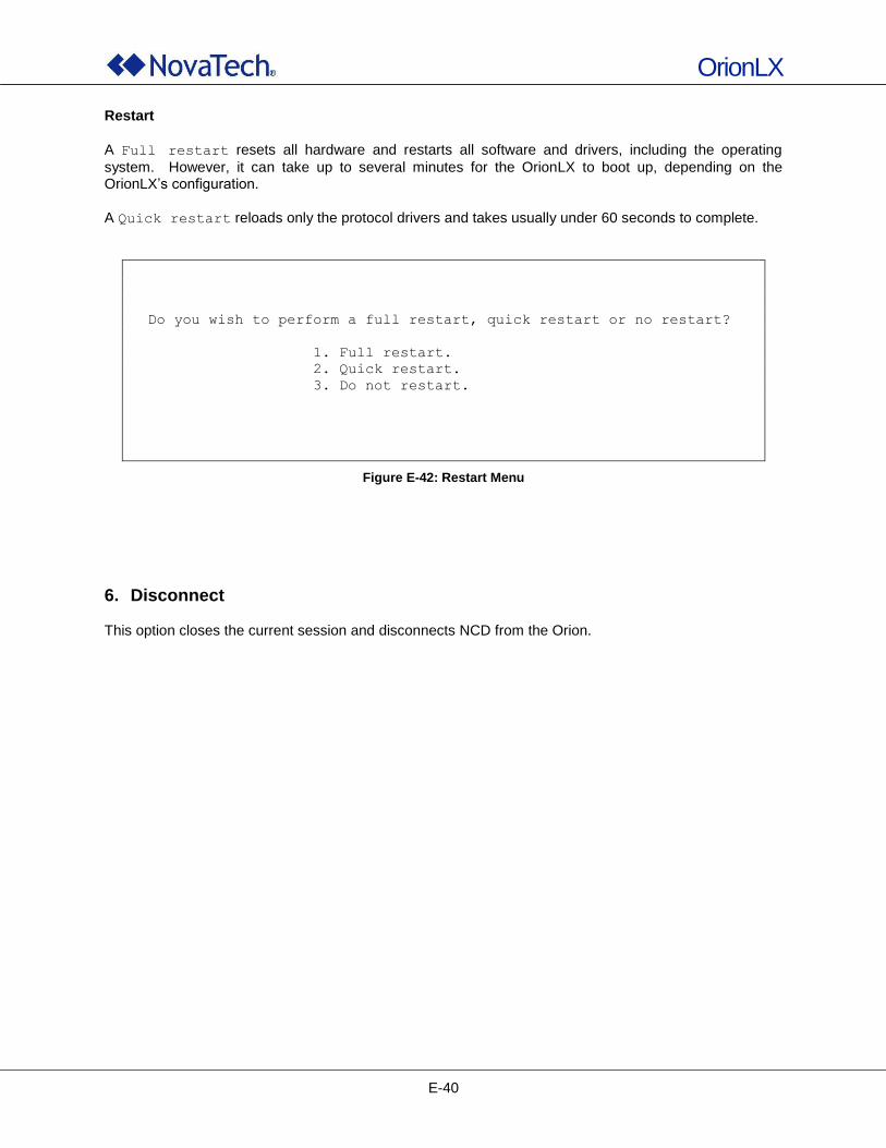
OrionLX
E-40
Restart
A Full restart resets all hardware and restarts all software and drivers, including the operating
system. However, it can take up to several minutes for the OrionLX to boot up, depending on the OrionLX‟s configuration.
A Quick restart reloads only the protocol drivers and takes usually under 60 seconds to complete.
Do you wish to perform a full restart, quick restart or no restart?
1. Full restart.
2. Quick restart.
3. Do not restart.
Figure E-42: Restart Menu
6. Disconnect This option closes the current session and disconnects NCD from the Orion.
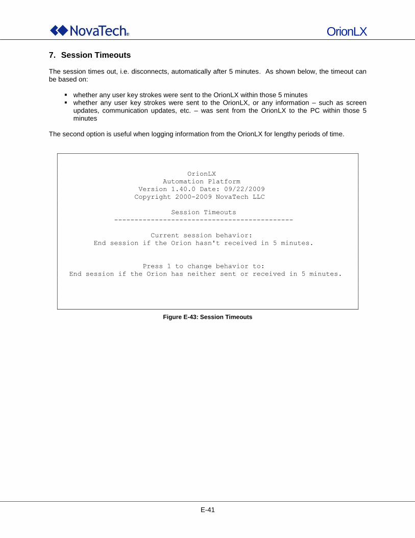
OrionLX
E-41
7. Session Timeouts The session times out, i.e. disconnects, automatically after 5 minutes. As shown below, the timeout can be based on:
whether any user key strokes were sent to the OrionLX within those 5 minutes whether any user key strokes were sent to the OrionLX, or any information – such as screen
updates, communication updates, etc. – was sent from the OrionLX to the PC within those 5 minutes
The second option is useful when logging information from the OrionLX for lengthy periods of time.
OrionLX
Automation Platform
Version 1.40.0 Date: 09/22/2009
Copyright 2000-2009 NovaTech LLC
Session Timeouts
--------------------------------------------
Current session behavior:
End session if the Orion hasn't received in 5 minutes.
Press 1 to change behavior to:
End session if the Orion has neither sent or received in 5 minutes.
Figure E-43: Session Timeouts
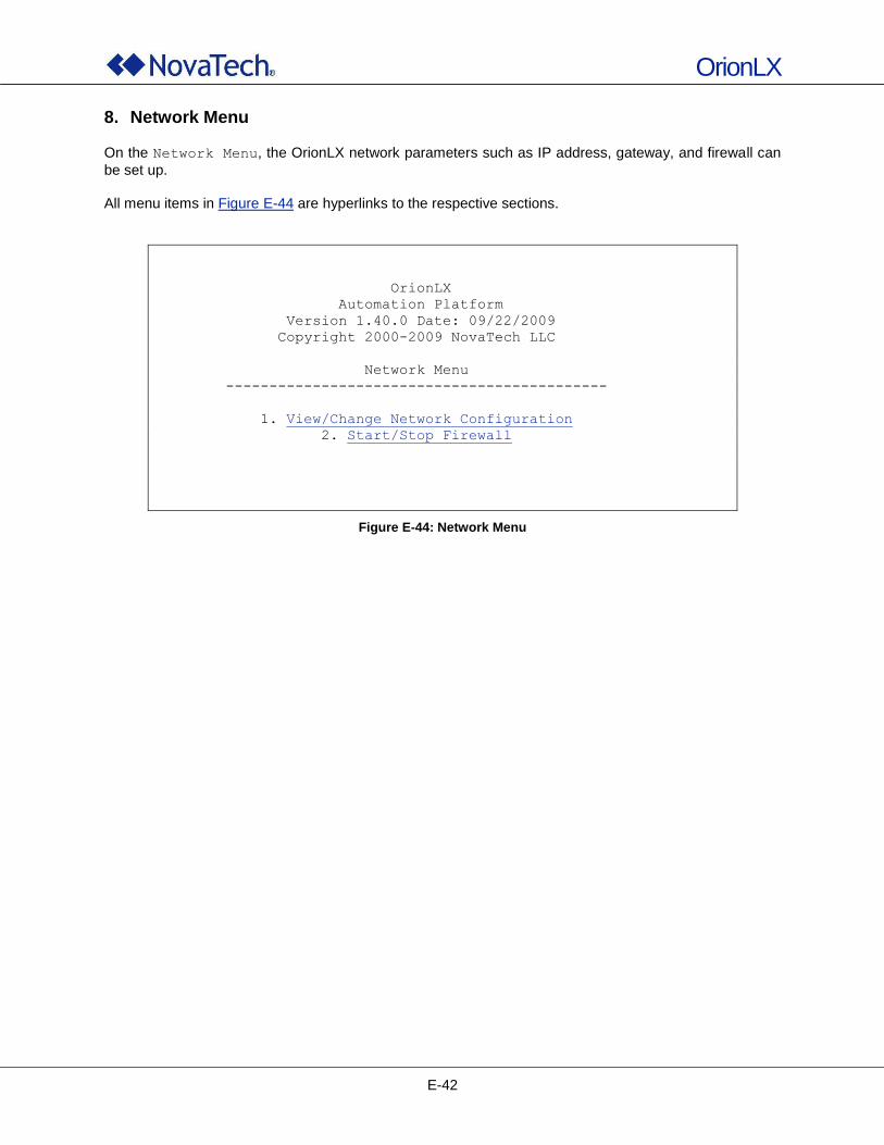
OrionLX
E-42
8. Network Menu
On the Network Menu, the OrionLX network parameters such as IP address, gateway, and firewall can
be set up. All menu items in Figure E-44 are hyperlinks to the respective sections.
OrionLX
Automation Platform
Version 1.40.0 Date: 09/22/2009
Copyright 2000-2009 NovaTech LLC
Network Menu
--------------------------------------------
1. View/Change Network Configuration
2. Start/Stop Firewall
Figure E-44: Network Menu
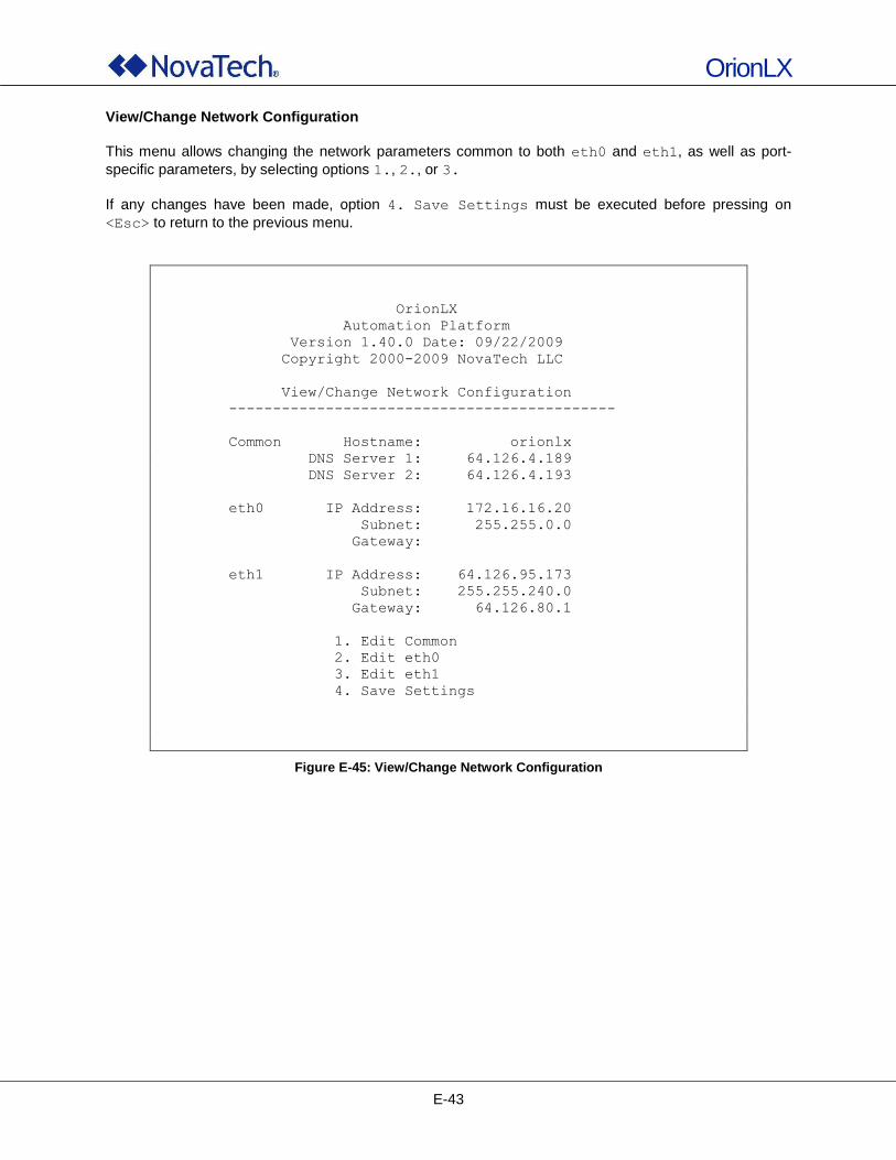
OrionLX
E-43
View/Change Network Configuration
This menu allows changing the network parameters common to both eth0 and eth1, as well as port-
specific parameters, by selecting options 1., 2., or 3.
If any changes have been made, option 4. Save Settings must be executed before pressing on
<Esc> to return to the previous menu.
OrionLX
Automation Platform
Version 1.40.0 Date: 09/22/2009
Copyright 2000-2009 NovaTech LLC
View/Change Network Configuration
--------------------------------------------
Common Hostname: orionlx
DNS Server 1: 64.126.4.189
DNS Server 2: 64.126.4.193
eth0 IP Address: 172.16.16.20
Subnet: 255.255.0.0
Gateway:
eth1 IP Address: 64.126.95.173
Subnet: 255.255.240.0
Gateway: 64.126.80.1
1. Edit Common
2. Edit eth0
3. Edit eth1
4. Save Settings
Figure E-45: View/Change Network Configuration
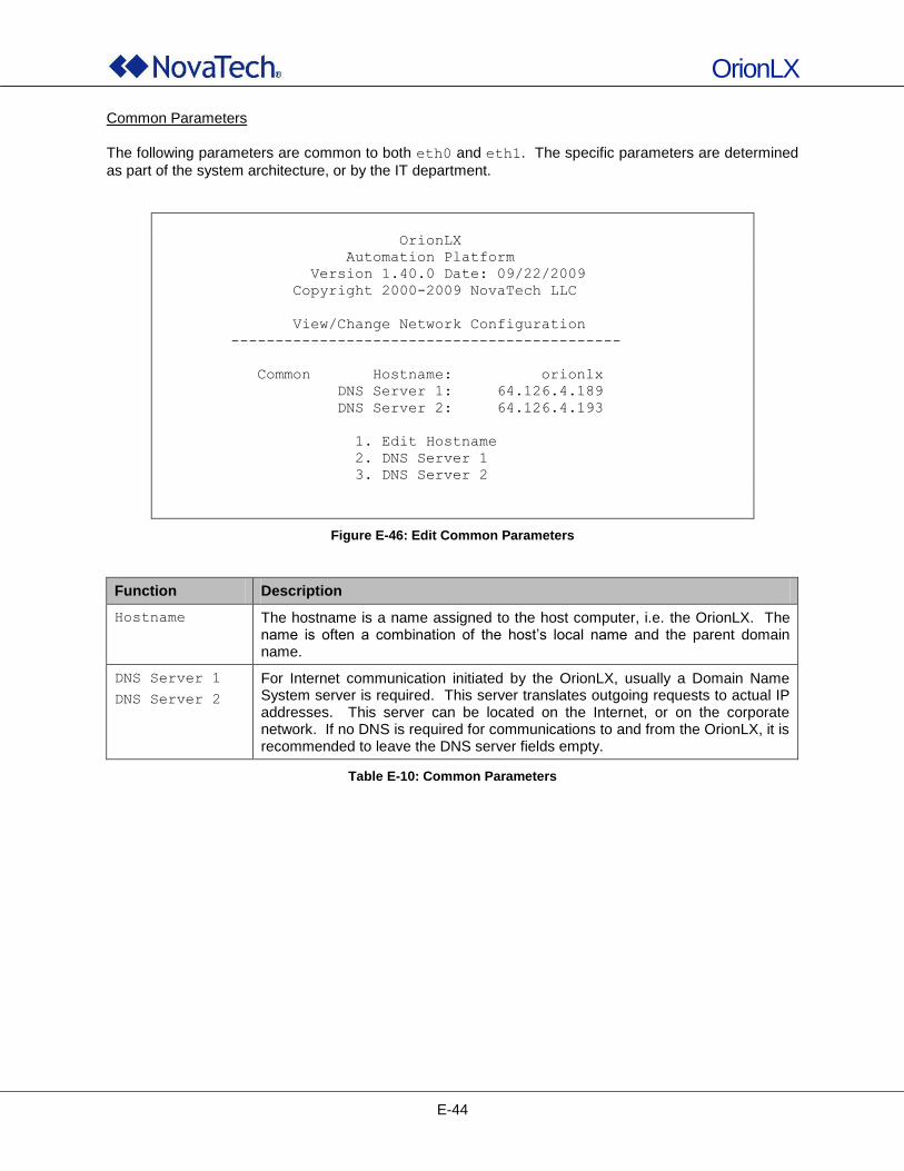
OrionLX
E-44
Common Parameters
The following parameters are common to both eth0 and eth1. The specific parameters are determined
as part of the system architecture, or by the IT department.
OrionLX
Automation Platform
Version 1.40.0 Date: 09/22/2009
Copyright 2000-2009 NovaTech LLC
View/Change Network Configuration
--------------------------------------------
Common Hostname: orionlx
DNS Server 1: 64.126.4.189
DNS Server 2: 64.126.4.193
1. Edit Hostname
2. DNS Server 1
3. DNS Server 2
Figure E-46: Edit Common Parameters
Function Description
Hostname The hostname is a name assigned to the host computer, i.e. the OrionLX. The name is often a combination of the host‟s local name and the parent domain name.
DNS Server 1
DNS Server 2
For Internet communication initiated by the OrionLX, usually a Domain Name System server is required. This server translates outgoing requests to actual IP addresses. This server can be located on the Internet, or on the corporate network. If no DNS is required for communications to and from the OrionLX, it is recommended to leave the DNS server fields empty.
Table E-10: Common Parameters
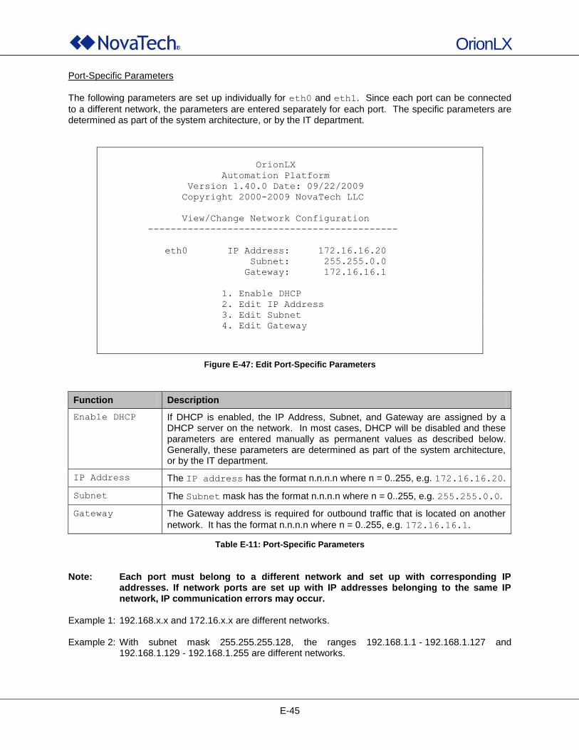
OrionLX
E-45
Port-Specific Parameters
The following parameters are set up individually for eth0 and eth1. Since each port can be connected
to a different network, the parameters are entered separately for each port. The specific parameters are determined as part of the system architecture, or by the IT department.
OrionLX
Automation Platform
Version 1.40.0 Date: 09/22/2009
Copyright 2000-2009 NovaTech LLC
View/Change Network Configuration
--------------------------------------------
eth0 IP Address: 172.16.16.20
Subnet: 255.255.0.0
Gateway: 172.16.16.1
1. Enable DHCP
2. Edit IP Address
3. Edit Subnet
4. Edit Gateway
Figure E-47: Edit Port-Specific Parameters
Function Description
Enable DHCP If DHCP is enabled, the IP Address, Subnet, and Gateway are assigned by a DHCP server on the network. In most cases, DHCP will be disabled and these parameters are entered manually as permanent values as described below. Generally, these parameters are determined as part of the system architecture, or by the IT department.
IP Address The IP address has the format n.n.n.n where n = 0..255, e.g. 172.16.16.20.
Subnet The Subnet mask has the format n.n.n.n where n = 0..255, e.g. 255.255.0.0.
Gateway The Gateway address is required for outbound traffic that is located on another
network. It has the format n.n.n.n where n = 0..255, e.g. 172.16.16.1.
Table E-11: Port-Specific Parameters
Note: Each port must belong to a different network and set up with corresponding IP
addresses. If network ports are set up with IP addresses belonging to the same IP network, IP communication errors may occur.
Example 1: 192.168.x.x and 172.16.x.x are different networks. Example 2: With subnet mask 255.255.255.128, the ranges 192.168.1.1 - 192.168.1.127 and
192.168.1.129 - 192.168.1.255 are different networks.
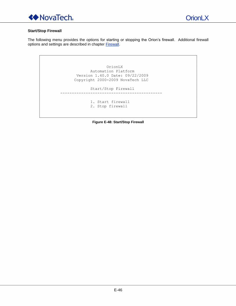
OrionLX
E-46
Start/Stop Firewall The following menu provides the options for starting or stopping the Orion‟s firewall. Additional firewall options and settings are described in chapter Firewall.
OrionLX
Automation Platform
Version 1.40.0 Date: 09/22/2009
Copyright 2000-2009 NovaTech LLC
Start/Stop Firewall
--------------------------------------------
1. Start firewall
2. Stop firewall
Figure E-48: Start/Stop Firewall

OrionLX
F-1
F. OrionLX Direct Video
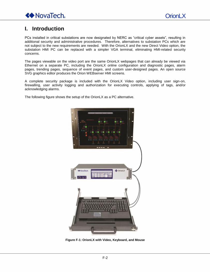
OrionLX
F-2
I. Introduction PCs installed in critical substations are now designated by NERC as “critical cyber assets”, resulting in additional security and administrative procedures. Therefore, alternatives to substation PCs which are not subject to the new requirements are needed. With the OrionLX and the new Direct Video option, the substation HMI PC can be replaced with a simpler VGA terminal, eliminating HMI-related security concerns. The pages viewable on the video port are the same OrionLX webpages that can already be viewed via Ethernet on a separate PC, including the OrionLX online configuration and diagnostic pages, alarm pages, trending pages, sequence of event pages, and custom user-designed pages. An open source SVG graphics editor produces the Orion WEBserver HMI screens. A complete security package is included with the OrionLX Video option, including user sign-on, firewalling, user activity logging and authorization for executing controls, applying of tags, and/or acknowledging alarms. The following figure shows the setup of the OrionLX as a PC alternative.
Figure F-1: OrionLX with Video, Keyboard, and Mouse
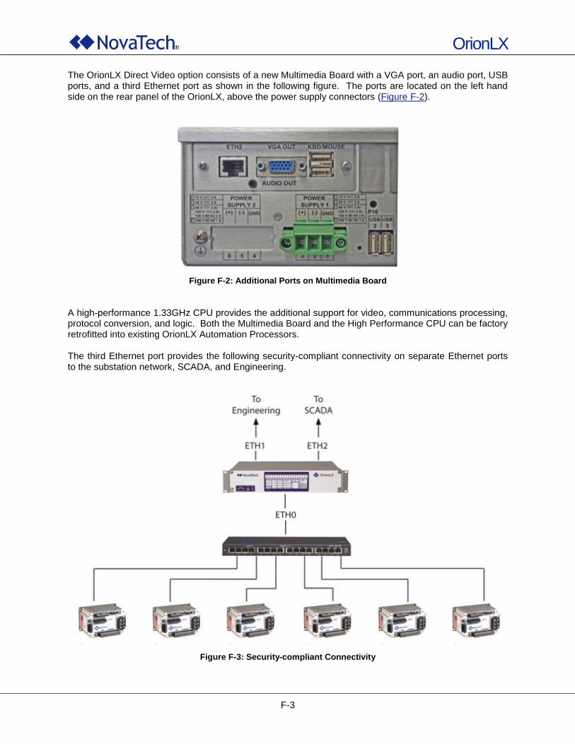
OrionLX
F-3
The OrionLX Direct Video option consists of a new Multimedia Board with a VGA port, an audio port, USB ports, and a third Ethernet port as shown in the following figure. The ports are located on the left hand side on the rear panel of the OrionLX, above the power supply connectors (Figure F-2).
Figure F-2: Additional Ports on Multimedia Board
A high-performance 1.33GHz CPU provides the additional support for video, communications processing, protocol conversion, and logic. Both the Multimedia Board and the High Performance CPU can be factory retrofitted into existing OrionLX Automation Processors. The third Ethernet port provides the following security-compliant connectivity on separate Ethernet ports to the substation network, SCADA, and Engineering.
Figure F-3: Security-compliant Connectivity
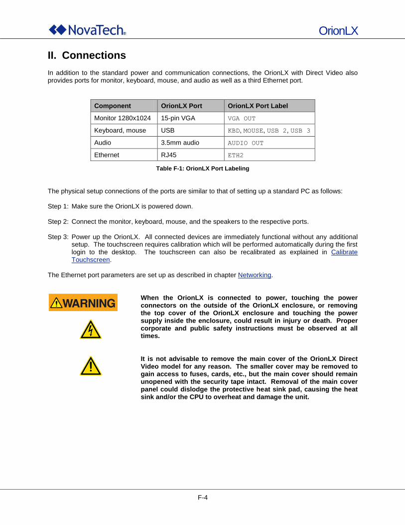
OrionLX
F-4
II. Connections In addition to the standard power and communication connections, the OrionLX with Direct Video also provides ports for monitor, keyboard, mouse, and audio as well as a third Ethernet port.
Component OrionLX Port OrionLX Port Label
Monitor 1280x1024 15-pin VGA VGA OUT
Keyboard, mouse USB KBD, MOUSE, USB 2, USB 3
Audio 3.5mm audio AUDIO OUT
Ethernet RJ45 ETH2
Table F-1: OrionLX Port Labeling
The physical setup connections of the ports are similar to that of setting up a standard PC as follows: Step 1: Make sure the OrionLX is powered down. Step 2: Connect the monitor, keyboard, mouse, and the speakers to the respective ports. Step 3: Power up the OrionLX. All connected devices are immediately functional without any additional
setup. The touchscreen requires calibration which will be performed automatically during the first login to the desktop. The touchscreen can also be recalibrated as explained in Calibrate Touchscreen.
The Ethernet port parameters are set up as described in chapter Networking.
When the OrionLX is connected to power, touching the power connectors on the outside of the OrionLX enclosure, or removing the top cover of the OrionLX enclosure and touching the power supply inside the enclosure, could result in injury or death. Proper corporate and public safety instructions must be observed at all times.
It is not advisable to remove the main cover of the OrionLX Direct Video model for any reason. The smaller cover may be removed to gain access to fuses, cards, etc., but the main cover should remain unopened with the security tape intact. Removal of the main cover panel could dislodge the protective heat sink pad, causing the heat sink and/or the CPU to overheat and damage the unit.
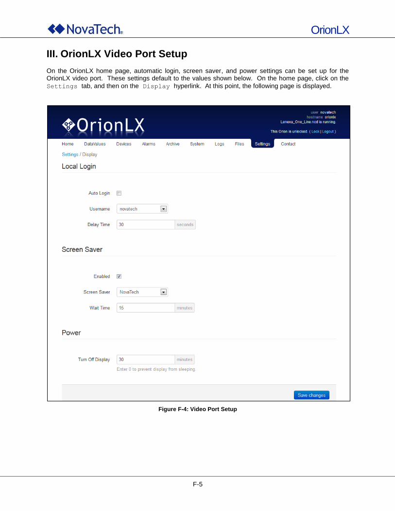
OrionLX
F-5
III. OrionLX Video Port Setup On the OrionLX home page, automatic login, screen saver, and power settings can be set up for the OrionLX video port. These settings default to the values shown below. On the home page, click on the
Settings tab, and then on the Display hyperlink. At this point, the following page is displayed.
Figure F-4: Video Port Setup
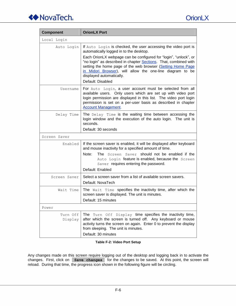
OrionLX
F-6
Component OrionLX Port
Local Login
Auto Login If Auto Login is checked, the user accessing the video port is
automatically logged in to the desktop.
Each OrionLX webpage can be configured for “login”, “unlock”, or
“no login” as described in chapter Sections. That, combined with
setting the home page of the web browser (Setting Home Page
in Midori Browser), will allow the one-line diagram to be
displayed automatically.
Default: Disabled
Username For Auto Login, a user account must be selected from all
available users. Only users which are set up with video port
login permission are displayed in this list. The video port login
permission is set on a per-user basis as described in chapter
Account Management.
Delay Time The Delay Time is the waiting time between accessing the
login window and the execution of the auto login. The unit is
seconds.
Default: 30 seconds
Screen Saver
Enabled If the screen saver is enabled, it will be displayed after keyboard
and mouse inactivity for a specified amount of time.
Note: The Screen Saver should not be enabled if the
Auto Login feature is enabled, because the Screen
Saver requires entering the password.
Default: Enabled
Screen Saver Select a screen saver from a list of available screen savers.
Default: NovaTech
Wait Time The Wait Time specifies the inactivity time, after which the
screen saver is displayed. The unit is minutes.
Default: 15 minutes
Power
Turn Off
Display
The Turn Off Display time specifies the inactivity time,
after which the screen is turned off. Any keyboard or mouse
activity turns the screen on again. Enter 0 to prevent the display
from sleeping. The unit is minutes.
Default: 30 minutes
Table F-2: Video Port Setup
Any changes made on this screen require logging out of the desktop and logging back in to activate the changes. First, click on Save changes for the changes to be saved. At this point, the screen will
reload. During that time, the progress icon shown in the following figure will be circling.
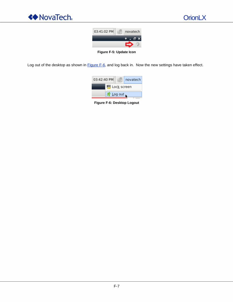
OrionLX
F-7
Figure F-5: Update Icon
Log out of the desktop as shown in Figure F-6, and log back in. Now the new settings have taken effect.
Figure F-6: Desktop Logout
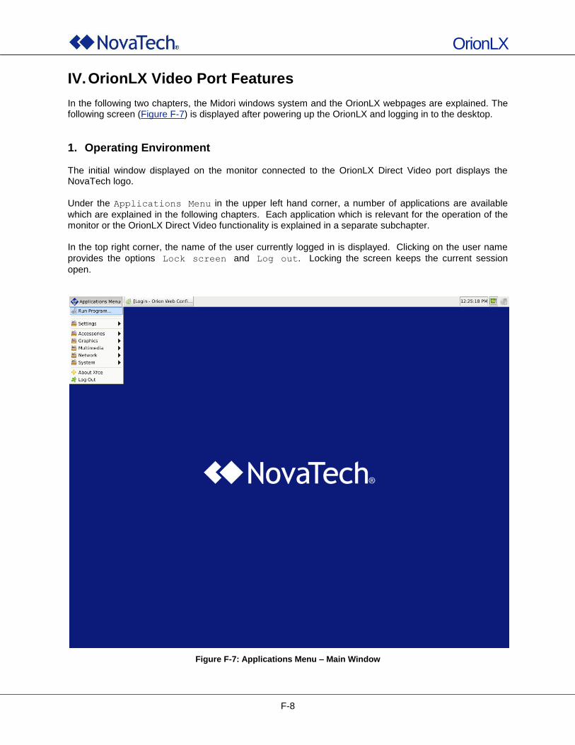
OrionLX
F-8
IV. OrionLX Video Port Features In the following two chapters, the Midori windows system and the OrionLX webpages are explained. The following screen (Figure F-7) is displayed after powering up the OrionLX and logging in to the desktop.
1. Operating Environment The initial window displayed on the monitor connected to the OrionLX Direct Video port displays the NovaTech logo.
Under the Applications Menu in the upper left hand corner, a number of applications are available
which are explained in the following chapters. Each application which is relevant for the operation of the monitor or the OrionLX Direct Video functionality is explained in a separate subchapter. In the top right corner, the name of the user currently logged in is displayed. Clicking on the user name
provides the options Lock screen and Log out. Locking the screen keeps the current session
open.
Figure F-7: Applications Menu – Main Window

OrionLX
F-9
Run Program This menu item opens a command line window in which any program can be executed if needed, and as instructed by NovaTech Technical Support.
Figure F-8: Run Program
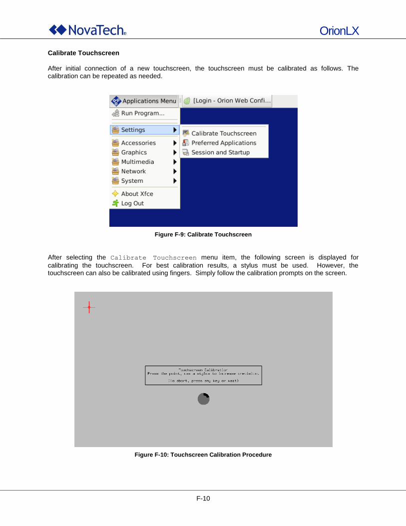
OrionLX
F-10
Calibrate Touchscreen After initial connection of a new touchscreen, the touchscreen must be calibrated as follows. The calibration can be repeated as needed.
Figure F-9: Calibrate Touchscreen
After selecting the Calibrate Touchscreen menu item, the following screen is displayed for
calibrating the touchscreen. For best calibration results, a stylus must be used. However, the touchscreen can also be calibrated using fingers. Simply follow the calibration prompts on the screen.
Figure F-10: Touchscreen Calibration Procedure
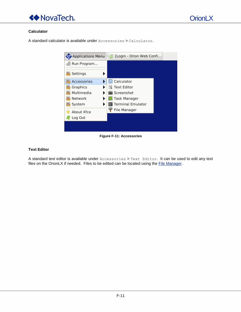
OrionLX
F-11
Calculator
A standard calculator is available under Accessories > Calculator.
Figure F-11: Accessories
Text Editor
A standard text editor is available under Accessories > Text Editor. It can be used to edit any text
files on the OrionLX if needed. Files to be edited can be located using the File Manager.
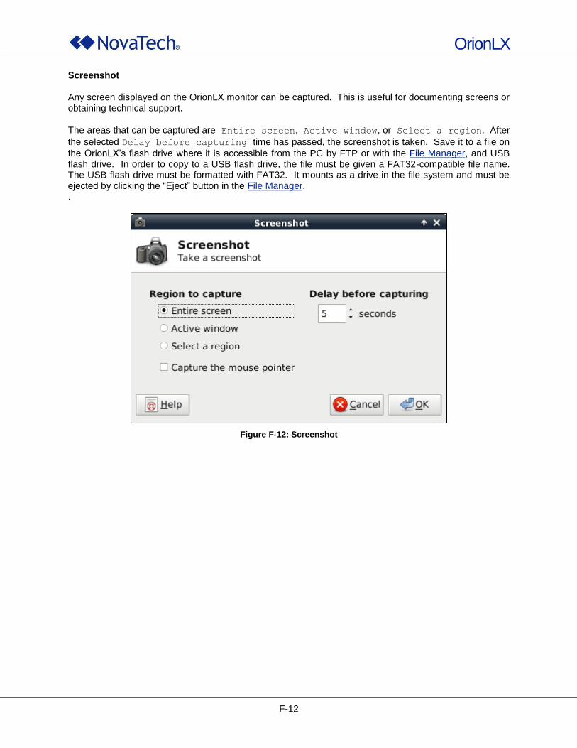
OrionLX
F-12
Screenshot Any screen displayed on the OrionLX monitor can be captured. This is useful for documenting screens or obtaining technical support.
The areas that can be captured are Entire screen, Active window, or Select a region. After
the selected Delay before capturing time has passed, the screenshot is taken. Save it to a file on
the OrionLX‟s flash drive where it is accessible from the PC by FTP or with the File Manager, and USB flash drive. In order to copy to a USB flash drive, the file must be given a FAT32-compatible file name. The USB flash drive must be formatted with FAT32. It mounts as a drive in the file system and must be ejected by clicking the “Eject” button in the File Manager. .
Figure F-12: Screenshot
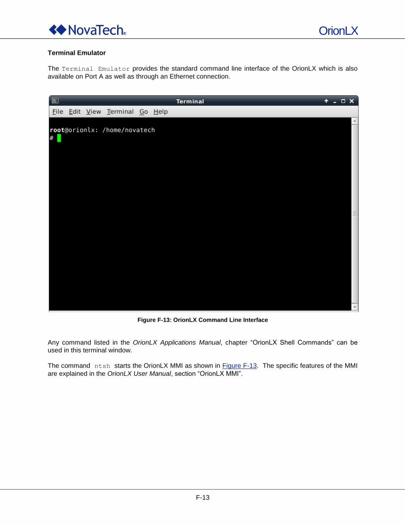
OrionLX
F-13
Terminal Emulator
The Terminal Emulator provides the standard command line interface of the OrionLX which is also
available on Port A as well as through an Ethernet connection.
Figure F-13: OrionLX Command Line Interface
Any command listed in the OrionLX Applications Manual, chapter “OrionLX Shell Commands” can be used in this terminal window.
The command ntsh starts the OrionLX MMI as shown in Figure F-13. The specific features of the MMI
are explained in the OrionLX User Manual, section “OrionLX MMI”.
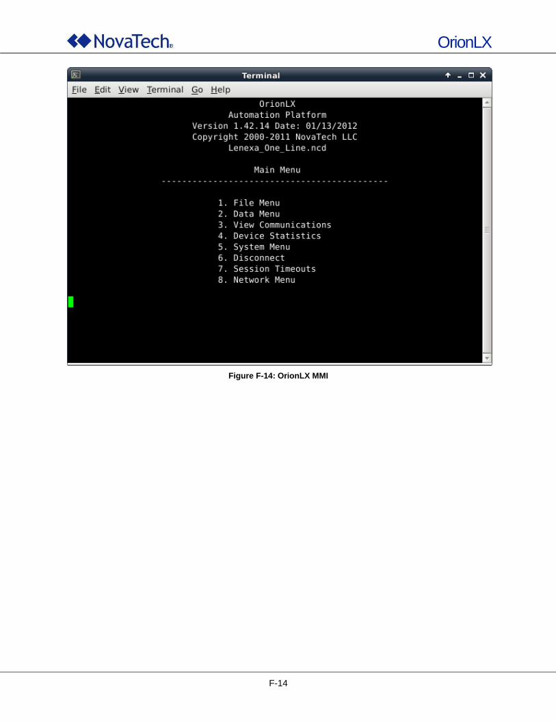
OrionLX
F-14
Figure F-14: OrionLX MMI
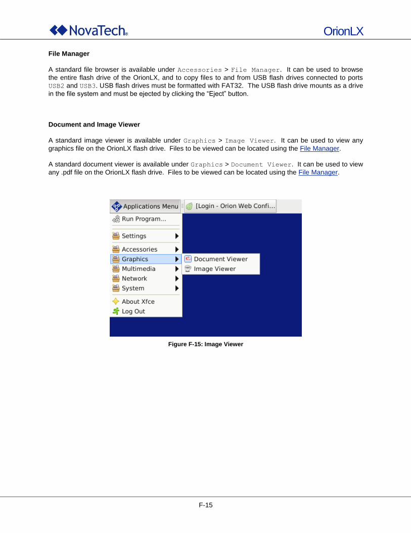
OrionLX
F-15
File Manager
A standard file browser is available under Accessories > File Manager. It can be used to browse
the entire flash drive of the OrionLX, and to copy files to and from USB flash drives connected to ports
USB2 and USB3. USB flash drives must be formatted with FAT32. The USB flash drive mounts as a drive
in the file system and must be ejected by clicking the “Eject” button. Document and Image Viewer
A standard image viewer is available under Graphics > Image Viewer. It can be used to view any
graphics file on the OrionLX flash drive. Files to be viewed can be located using the File Manager.
A standard document viewer is available under Graphics > Document Viewer. It can be used to view
any .pdf file on the OrionLX flash drive. Files to be viewed can be located using the File Manager.
Figure F-15: Image Viewer
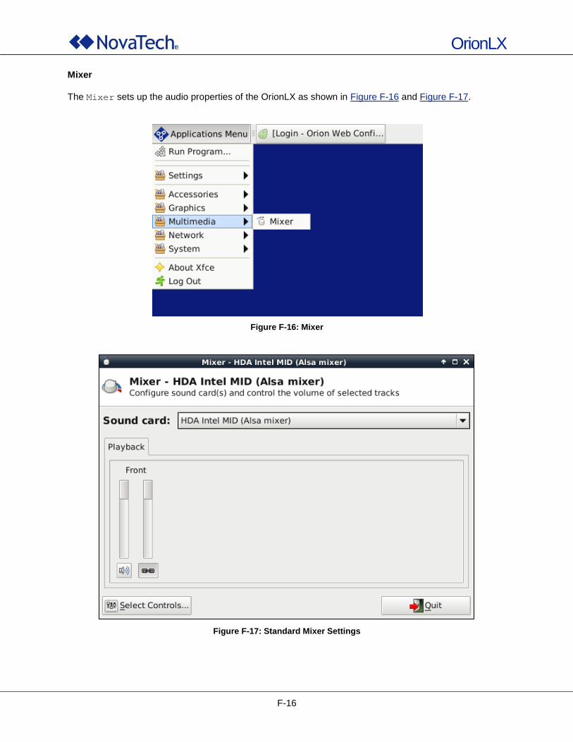
OrionLX
F-16
Mixer
The Mixer sets up the audio properties of the OrionLX as shown in Figure F-16 and Figure F-17.
Figure F-16: Mixer
Figure F-17: Standard Mixer Settings
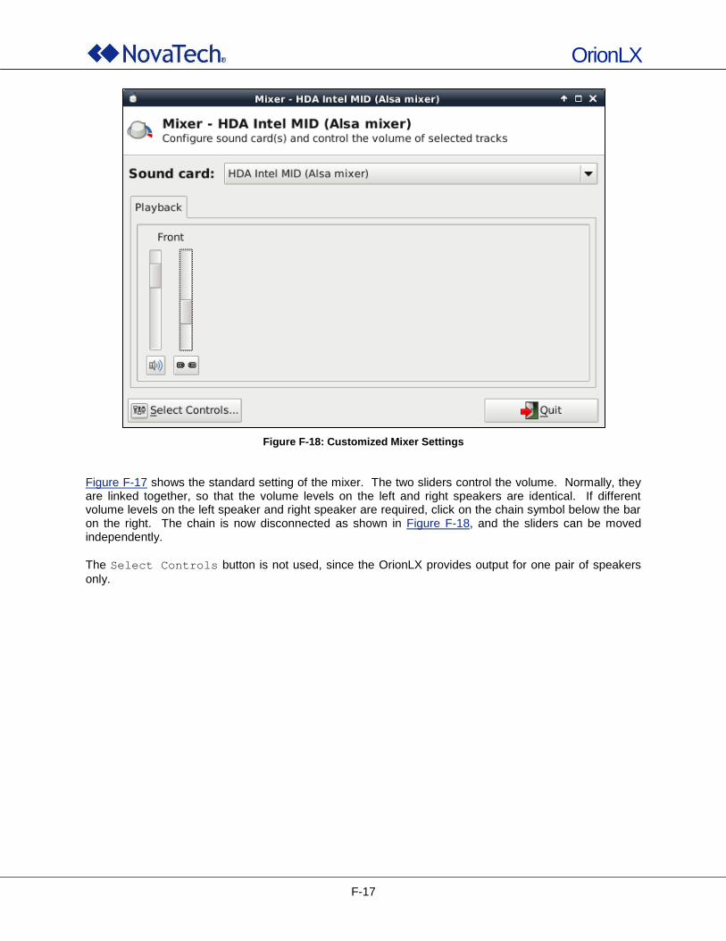
OrionLX
F-17
Figure F-18: Customized Mixer Settings
Figure F-17 shows the standard setting of the mixer. The two sliders control the volume. Normally, they are linked together, so that the volume levels on the left and right speakers are identical. If different volume levels on the left speaker and right speaker are required, click on the chain symbol below the bar on the right. The chain is now disconnected as shown in Figure F-18, and the sliders can be moved independently.
The Select Controls button is not used, since the OrionLX provides output for one pair of speakers
only.
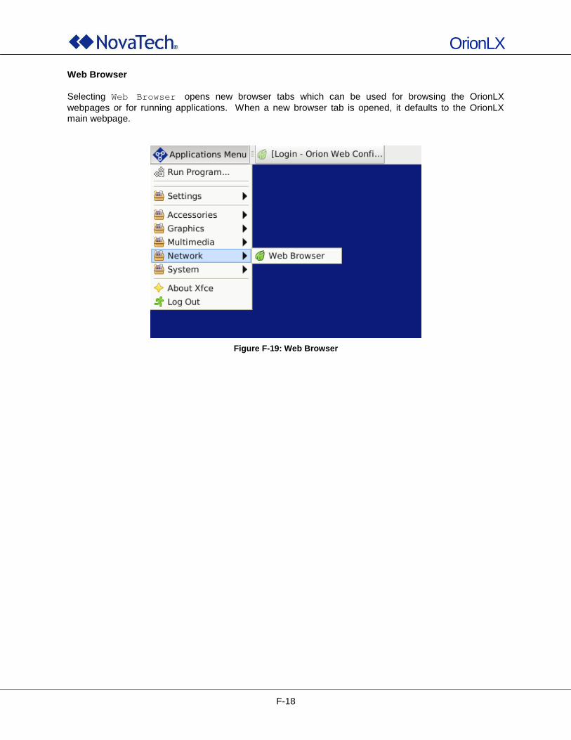
OrionLX
F-18
Web Browser
Selecting Web Browser opens new browser tabs which can be used for browsing the OrionLX
webpages or for running applications. When a new browser tab is opened, it defaults to the OrionLX main webpage.
Figure F-19: Web Browser
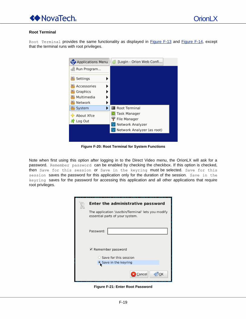
OrionLX
F-19
Root Terminal
Root Terminal provides the same functionality as displayed in Figure F-13 and Figure F-14, except
that the terminal runs with root privileges.
Figure F-20: Root Terminal for System Functions
Note when first using this option after logging in to the Direct Video menu, the OrionLX will ask for a
password. Remember password can be enabled by checking the checkbox. If this option is checked,
then Save for this session or Save in the keyring must be selected. Save for this
session saves the password for this application only for the duration of the session. Save in the
keyring saves for the password for accessing this application and all other applications that require
root privileges.
Figure F-21: Enter Root Password
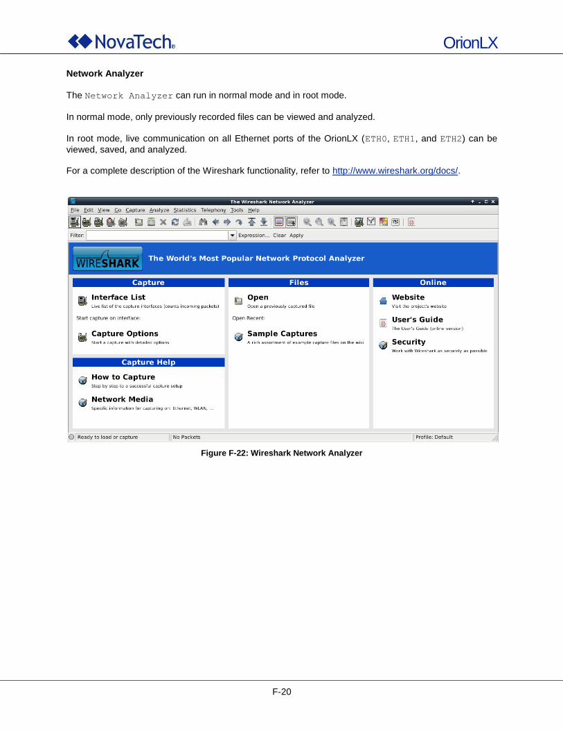
OrionLX
F-20
Network Analyzer
The Network Analyzer can run in normal mode and in root mode.
In normal mode, only previously recorded files can be viewed and analyzed.
In root mode, live communication on all Ethernet ports of the OrionLX (ETH0, ETH1, and ETH2) can be
viewed, saved, and analyzed. For a complete description of the Wireshark functionality, refer to http://www.wireshark.org/docs/.
Figure F-22: Wireshark Network Analyzer
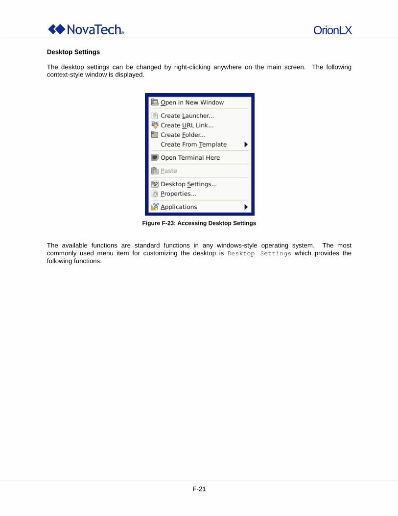
OrionLX
F-21
Desktop Settings The desktop settings can be changed by right-clicking anywhere on the main screen. The following context-style window is displayed.
Figure F-23: Accessing Desktop Settings
The available functions are standard functions in any windows-style operating system. The most
commonly used menu item for customizing the desktop is Desktop Settings which provides the
following functions.
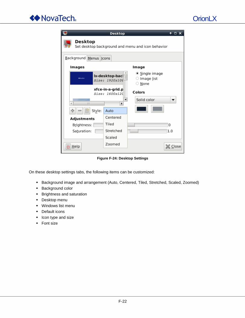
OrionLX
F-22
Figure F-24: Desktop Settings
On these desktop settings tabs, the following items can be customized:
Background image and arrangement (Auto, Centered, Tiled, Stretched, Scaled, Zoomed)
Background color
Brightness and saturation
Desktop menu
Windows list menu
Default icons
Icon type and size
Font size
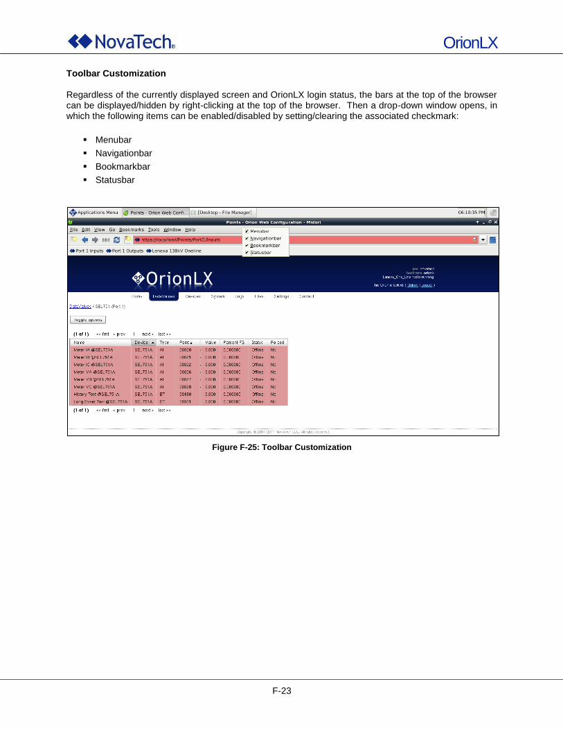
OrionLX
F-23
Toolbar Customization Regardless of the currently displayed screen and OrionLX login status, the bars at the top of the browser can be displayed/hidden by right-clicking at the top of the browser. Then a drop-down window opens, in which the following items can be enabled/disabled by setting/clearing the associated checkmark:
Menubar
Navigationbar
Bookmarkbar
Statusbar
Figure F-25: Toolbar Customization
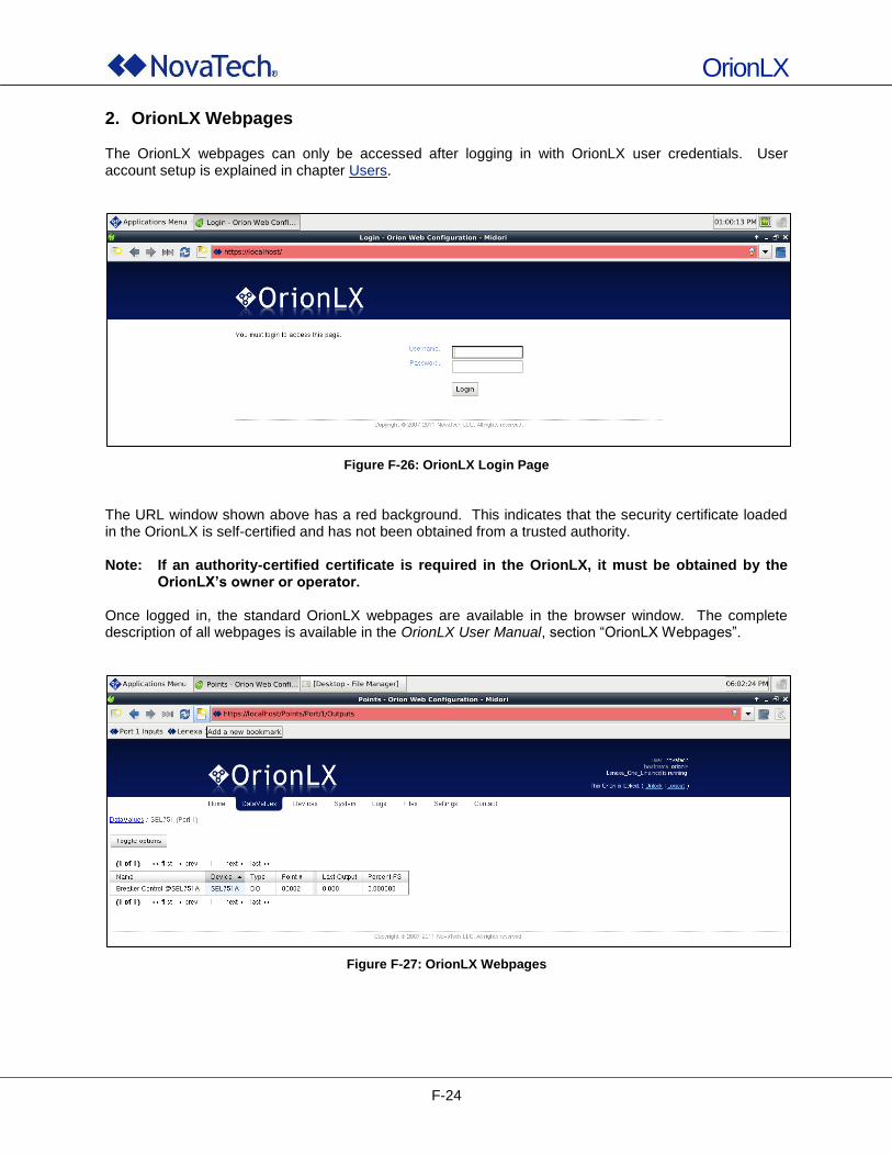
OrionLX
F-24
2. OrionLX Webpages The OrionLX webpages can only be accessed after logging in with OrionLX user credentials. User account setup is explained in chapter Users.
Figure F-26: OrionLX Login Page
The URL window shown above has a red background. This indicates that the security certificate loaded in the OrionLX is self-certified and has not been obtained from a trusted authority. Note: If an authority-certified certificate is required in the OrionLX, it must be obtained by the
OrionLX’s owner or operator. Once logged in, the standard OrionLX webpages are available in the browser window. The complete description of all webpages is available in the OrionLX User Manual, section “OrionLX Webpages”.
Figure F-27: OrionLX Webpages
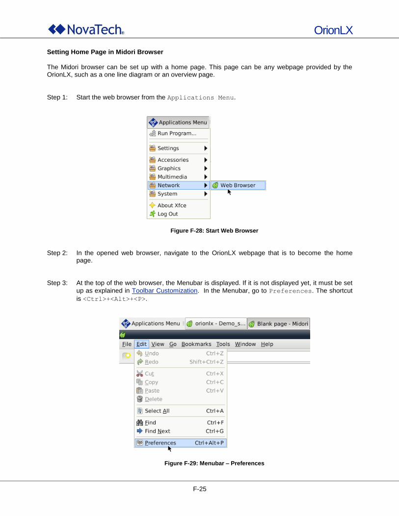
OrionLX
F-25
Setting Home Page in Midori Browser The Midori browser can be set up with a home page. This page can be any webpage provided by the OrionLX, such as a one line diagram or an overview page.
Step 1: Start the web browser from the Applications Menu.
Figure F-28: Start Web Browser
Step 2: In the opened web browser, navigate to the OrionLX webpage that is to become the home
page. Step 3: At the top of the web browser, the Menubar is displayed. If it is not displayed yet, it must be set
up as explained in Toolbar Customization. In the Menubar, go to Preferences. The shortcut
is <Ctrl>+<Alt>+<P>.
Figure F-29: Menubar – Preferences
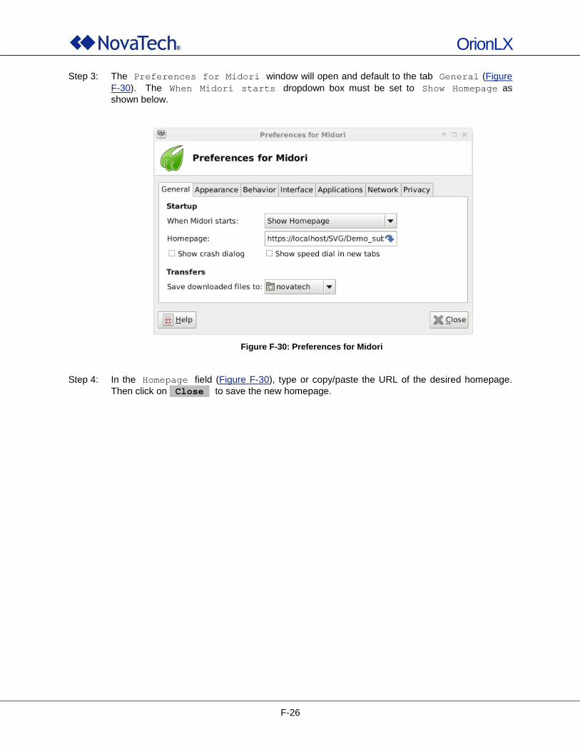
OrionLX
F-26
Step 3: The Preferences for Midori window will open and default to the tab General (Figure
F-30). The When Midori starts dropdown box must be set to Show Homepage as
shown below.
Figure F-30: Preferences for Midori
Step 4: In the Homepage field (Figure F-30), type or copy/paste the URL of the desired homepage.
Then click on Close to save the new homepage.
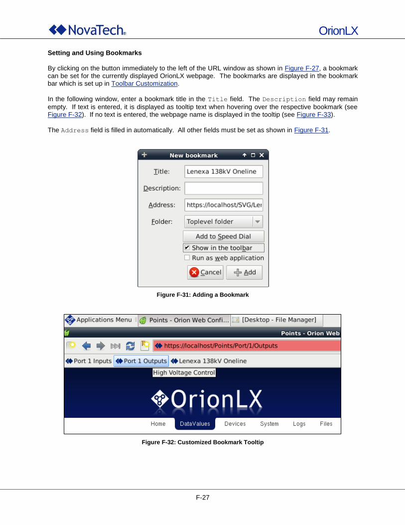
OrionLX
F-27
Setting and Using Bookmarks By clicking on the button immediately to the left of the URL window as shown in Figure F-27, a bookmark can be set for the currently displayed OrionLX webpage. The bookmarks are displayed in the bookmark bar which is set up in Toolbar Customization.
In the following window, enter a bookmark title in the Title field. The Description field may remain
empty. If text is entered, it is displayed as tooltip text when hovering over the respective bookmark (see Figure F-32). If no text is entered, the webpage name is displayed in the tooltip (see Figure F-33).
The Address field is filled in automatically. All other fields must be set as shown in Figure F-31.
Figure F-31: Adding a Bookmark
Figure F-32: Customized Bookmark Tooltip
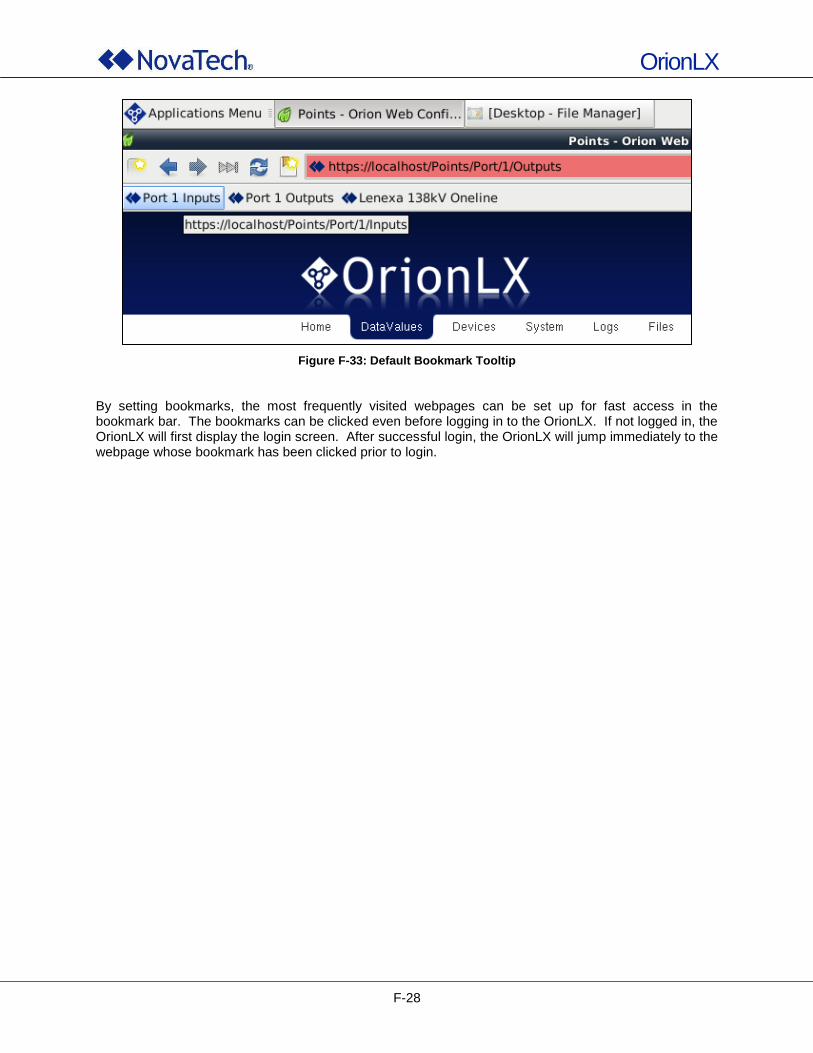
OrionLX
F-28
Figure F-33: Default Bookmark Tooltip
By setting bookmarks, the most frequently visited webpages can be set up for fast access in the bookmark bar. The bookmarks can be clicked even before logging in to the OrionLX. If not logged in, the OrionLX will first display the login screen. After successful login, the OrionLX will jump immediately to the webpage whose bookmark has been clicked prior to login.

OrionLX
G-1
G. Glossary
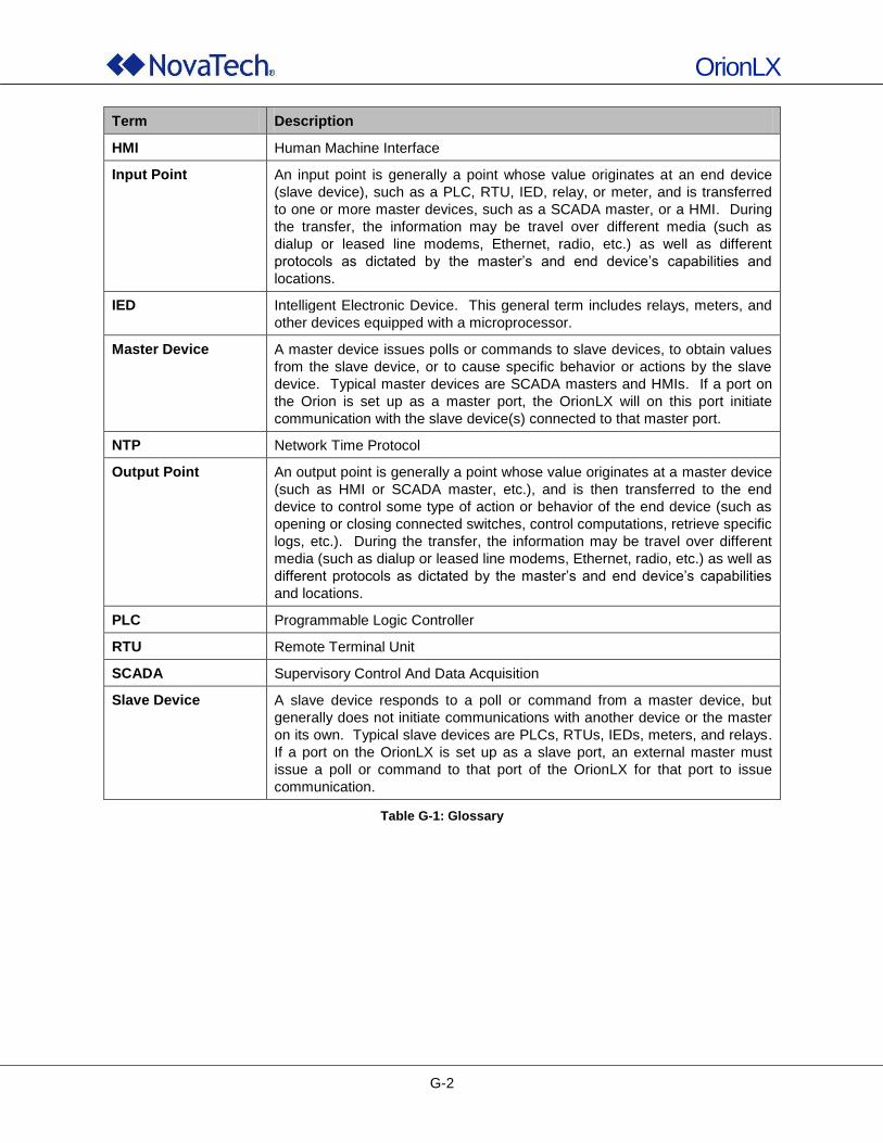
OrionLX
G-2
Term Description
HMI Human Machine Interface
Input Point An input point is generally a point whose value originates at an end device
(slave device), such as a PLC, RTU, IED, relay, or meter, and is transferred
to one or more master devices, such as a SCADA master, or a HMI. During
the transfer, the information may be travel over different media (such as
dialup or leased line modems, Ethernet, radio, etc.) as well as different
protocols as dictated by the master‟s and end device‟s capabilities and
locations.
IED Intelligent Electronic Device. This general term includes relays, meters, and
other devices equipped with a microprocessor.
Master Device A master device issues polls or commands to slave devices, to obtain values
from the slave device, or to cause specific behavior or actions by the slave
device. Typical master devices are SCADA masters and HMIs. If a port on
the Orion is set up as a master port, the OrionLX will on this port initiate
communication with the slave device(s) connected to that master port.
NTP Network Time Protocol
Output Point An output point is generally a point whose value originates at a master device
(such as HMI or SCADA master, etc.), and is then transferred to the end
device to control some type of action or behavior of the end device (such as
opening or closing connected switches, control computations, retrieve specific
logs, etc.). During the transfer, the information may be travel over different
media (such as dialup or leased line modems, Ethernet, radio, etc.) as well as
different protocols as dictated by the master‟s and end device‟s capabilities
and locations.
PLC Programmable Logic Controller
RTU Remote Terminal Unit
SCADA Supervisory Control And Data Acquisition
Slave Device A slave device responds to a poll or command from a master device, but
generally does not initiate communications with another device or the master
on its own. Typical slave devices are PLCs, RTUs, IEDs, meters, and relays.
If a port on the OrionLX is set up as a slave port, an external master must
issue a poll or command to that port of the OrionLX for that port to issue
communication.
Table G-1: Glossary

OrionLX
H-1
H. Additional Documentation
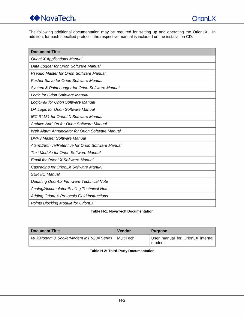
OrionLX
H-2
The following additional documentation may be required for setting up and operating the OrionLX. In addition, for each specified protocol, the respective manual is included on the installation CD.
Document Title
OrionLX Applications Manual
Data Logger for Orion Software Manual
Pseudo Master for Orion Software Manual
Pusher Slave for Orion Software Manual
System & Point Logger for Orion Software Manual
Logic for Orion Software Manual
LogicPak for Orion Software Manual
DA Logic for Orion Software Manual
IEC 61131 for OrionLX Software Manual
Archive Add-On for Orion Software Manual
Web Alarm Annunciator for Orion Software Manual
DNP3 Master Software Manual
Alarm/Archive/Retentive for Orion Software Manual
Text Module for Orion Software Manual
Email for OrionLX Software Manual
Cascading for OrionLX Software Manual
SER I/O Manual
Updating OrionLX Firmware Technical Note
Analog/Accumulator Scaling Technical Note
Adding OrionLX Protocols Field Instructions
Points Blocking Module for OrionLX
Table H-1: NovaTech Documentation
Document Title Vendor Purpose
MultiModem & SocketModem MT 9234 Series MultiTech User manual for OrionLX internal modem.
Table H-2: Third-Party Documentation
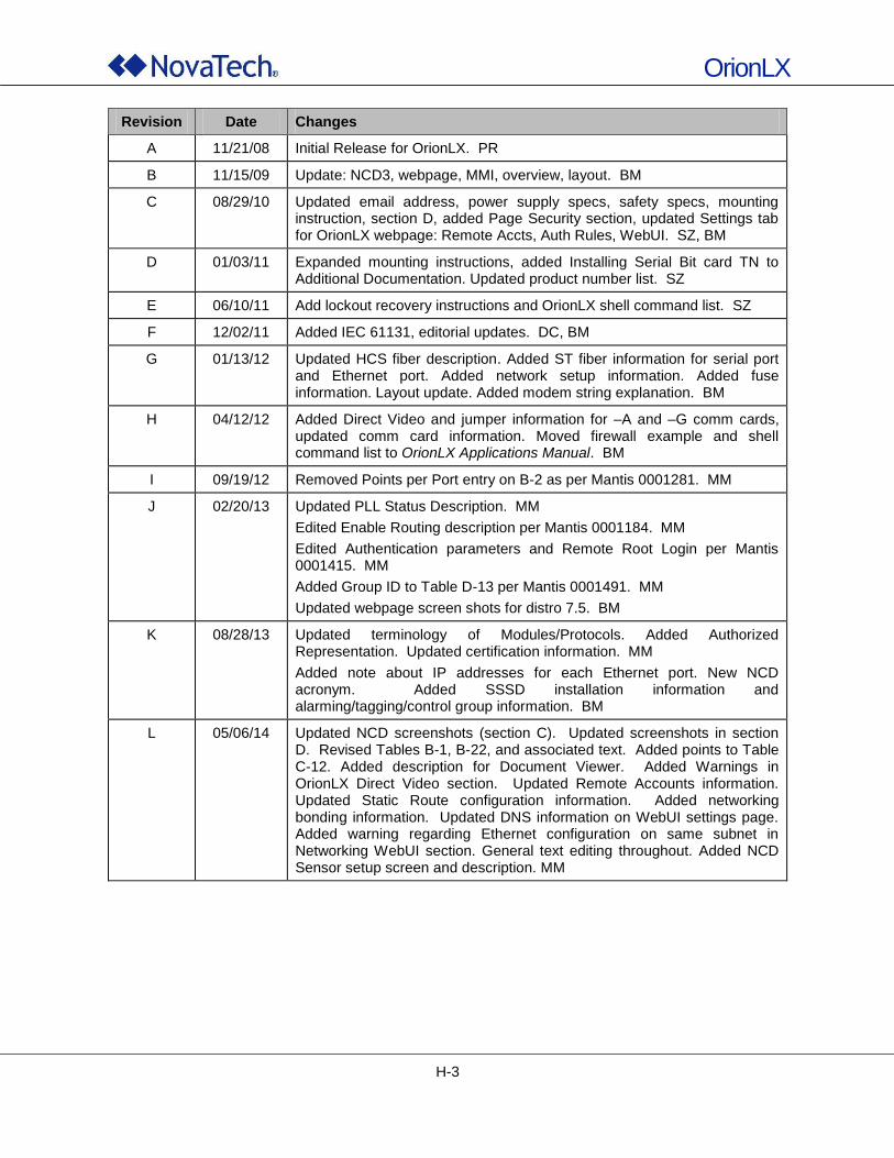
OrionLX
H-3
Revision Date Changes
A 11/21/08 Initial Release for OrionLX. PR
B 11/15/09 Update: NCD3, webpage, MMI, overview, layout. BM
C 08/29/10 Updated email address, power supply specs, safety specs, mounting instruction, section D, added Page Security section, updated Settings tab for OrionLX webpage: Remote Accts, Auth Rules, WebUI. SZ, BM
D 01/03/11 Expanded mounting instructions, added Installing Serial Bit card TN to Additional Documentation. Updated product number list. SZ
E 06/10/11 Add lockout recovery instructions and OrionLX shell command list. SZ
F 12/02/11 Added IEC 61131, editorial updates. DC, BM
G 01/13/12 Updated HCS fiber description. Added ST fiber information for serial port and Ethernet port. Added network setup information. Added fuse information. Layout update. Added modem string explanation. BM
H 04/12/12 Added Direct Video and jumper information for –A and –G comm cards, updated comm card information. Moved firewall example and shell command list to OrionLX Applications Manual. BM
I 09/19/12 Removed Points per Port entry on B-2 as per Mantis 0001281. MM
J 02/20/13 Updated PLL Status Description. MM
Edited Enable Routing description per Mantis 0001184. MM
Edited Authentication parameters and Remote Root Login per Mantis 0001415. MM
Added Group ID to Table D-13 per Mantis 0001491. MM
Updated webpage screen shots for distro 7.5. BM
K 08/28/13 Updated terminology of Modules/Protocols. Added Authorized Representation. Updated certification information. MM
Added note about IP addresses for each Ethernet port. New NCD acronym. Added SSSD installation information and alarming/tagging/control group information. BM
L 05/06/14 Updated NCD screenshots (section C). Updated screenshots in section D. Revised Tables B-1, B-22, and associated text. Added points to Table C-12. Added description for Document Viewer. Added Warnings in OrionLX Direct Video section. Updated Remote Accounts information. Updated Static Route configuration information. Added networking bonding information. Updated DNS information on WebUI settings page. Added warning regarding Ethernet configuration on same subnet in Networking WebUI section. General text editing throughout. Added NCD Sensor setup screen and description. MM