Embed Size (px)
Citation preview

This document represents work in progress. Design parameters are best estimates as of the report date.
Comments and questions may be directed to R. Siemann, E. Colby, or R. Noble.
ORION Research Facility Technical Design Study
April 12, 2002
Stanford Linear Accelerator Center Stanford University
Stanford, California 94309 USA
Prepared with support from the U.S. Department of Energy under contract DE-AC03-76SFO0515.
1

Table of Contents
Abstract .................................................................................................................................................................3 1 Introduction...................................................................................................................................................4
1.1 Accelerators and the High-Energy Frontier ...........................................................................4 1.2 Goals of the ORION Project ...........................................................................................................5
2 Design Considerations.........................................................................................................................6 2.1 Overview.....................................................................................................................................................6 2.2 Design Criteria and Beam Requirements.................................................................................7 2.3 ORION Facility Design......................................................................................................................9
2.3.1 Machine Parameters .....................................................................................................................9 2.3.2 Electron Source and Injector.................................................................................................10 2.3.3 Beam Manipulation, Extraction and Transfer.............................................................14 2.3.4 End-to-End Simulations...........................................................................................................23 2.3.5 Radiation Shielding ....................................................................................................................32
3 Facility Components ...........................................................................................................................33 3.1 Overview...................................................................................................................................................33 3.2 RF Photoinjector...................................................................................................................................33 3.3 Drive Laser System ............................................................................................................................37 3.4 Radio Frequency System.................................................................................................................40 3.5 Transfer Lines ........................................................................................................................................42 3.6 Diagnostics ..............................................................................................................................................44 3.7 Conventional Facilities.....................................................................................................................46
3.7.1 Laser Rooms...................................................................................................................................46 3.7.2 Experimental Halls .....................................................................................................................46 3.7.3 Staging and Construction Areas..........................................................................................47 3.7.4 Data Acquisition Room............................................................................................................47 3.7.5 Utilities and Services.................................................................................................................48
3.8 Control Systems....................................................................................................................................49 3.9 Protection Systems..............................................................................................................................49
Acknowledgements...................................................................................................................................50 References.........................................................................................................................................................50
2

Abstract
This document presents the baseline technical design for the ORION Research Facility at the Stanford Linear Accelerator Center, Stanford University. The goal of ORION is to establish and operate a user-oriented facility for understanding the physics and developing the technology for future high-energy particle accelerators. The ORION Facility will bring together the needed resources for performing a wide range of experiments in advanced accelerator and beam physics, and have these available and operating for the experimenters. The facility has as its centerpiece the Next Linear Collider Test Accelerator (NLCTA) within End Station B at the SLAC Central Research Yard. That site will be modified with the addition of a new high-brightness photoinjector, its associated drive laser and rf power system, a user laser room, a low-energy experimental hall supplied with beams up to approximately 60 MeV in energy, and a high-energy hall supplied with beams up to 350 MeV.
3

1 Introduction
1.1 Accelerators and the High-Energy Frontier
Particle physics is addressing fundamental questions of the origin of mass and the observed symmetries in Nature. At the highest energies we see Nature on the smallest of scales, which is the foundation upon which the origin of our Universe, stable matter, galaxies, and ultimately life, depends. Particle physics is motivated not just by basic scientific questions, but also by the very human questions regarding our own origins. Historically, these types of questions are answered at the energy frontier, and the exponential growth of center-of-mass energy and fundamental discoveries have gone hand-in-hand. Particle accelerators have become our microscopes to study Nature, and the previous century has seen us peer down to distances nearly one-billionth the size of an atom. Today we are on the verge of profound discoveries in physics that may reveal to us why objects have mass, why matter predominates over antimatter, and even how our Universe was born. Only with higher energy accelerators will we find answers to these questions.
Since the invention of the first optical microscopes 400 years ago, people have strived to see the building blocks that make up our world. Optical microscopes culminated in the early-twentieth century with the imaging of basic structures within living cells. To image the smaller objects within our cells, including the chromosomes containing genetic material, the use of visible light was replaced with neutrons and more energetic electrons that could be precisely focused to delve deeper. The technologies of electron microscopy and neutron scattering revolutionized biochemistry permitting us to visualize the precise arrangement of atoms and molecules in our cells. From such knowledge, the molecular basis of our genetic code was discovered.
The techniques for using energetic particles to observe objects at smaller scales not only revolutionized biology in the past century, but also physics. We know of only one simple, scalable technique to accelerate charged particles, and that is to provide an electric field parallel to the particle’s velocity. The way to get to higher energies in a shorter distance is to create higher electric fields. High-energy particle accelerators today are large because our technology only allows us to produce macroscopic, stable electric fields up to about 107 V/cm using metallic, electromagnetic cavities. This field is equivalent to applying 0.1 eV over one Angstrom, the size of a neutral atom, and corresponds roughly to the field needed to ionize and hence damage an ideal, metallic surface. Beyond the 1012 eV energy scale, linear accelerators with extra length needed for final beam focusing will become tens to hundreds of kilometers long and unaffordable to build. To dramatically shorten the length of high-energy accelerators, we must learn to create and control, over macroscopic lengths, electric fields and energy densities much higher than the present limits.
During the last four decades, many creative ideas have been suggested for producing large electric fields in various media including metals, dielectrics and plasmas. In all cases, one must ultimately use some electromagnetic field mode supported by a media or modified by material boundaries to produce a longitudinal component of the electric field to accelerate particles. In the 1970’s it was noted that longitudinal, electron plasma oscillations could provide accelerating fields up to order n1/2 V/cm, where n is the electron density in units of cm-3, before wave-breaking and plasma turbulence ensue. For example, high-density laboratory plasmas with 1018 electrons/cm3 can in principle produce 109 V/cm acceleration fields. The advent of high peak-
4

power lasers and intense charged-particle beams able to excite large-amplitude, electromagnetic modes in different media resulted in many small experiments being mounted worldwide during the last twenty years to test novel laser and plasma accelerator concepts. The scientific interest in acceleration topics quickly grew, and since 1982 there has been an Advanced Accelerator Concepts Workshop held every two years, which now attracts two to three hundred participants (Ref. 1).
Advanced accelerator research, with its goal of understanding the physics and developing the technologies for reaching high energies, is essential for the future of high-energy physics. With many new, aggressive acceleration experiments being contemplated by university groups, a state-of-the-art experimental facility with a wide range of electron beam energies, variable bunch length and charge, micron-wavelength laser capability, and laboratory infrastructure is needed. Testing new acceleration concepts rapidly and then turning the concepts into prototypical particle accelerators will require the resources of the national labs teamed with the academic community.
1.2 Goals of the ORION Project
The central goal of the ORION Project is to establish and operate a user-oriented facility for understanding the physics and developing the technology for future high-energy particle accelerators. Experiments usually have both state-of-the-art and conventional components with both being critical for success. Often the conventional components require substantial effort to build, maintain and operate. The ORION Research Facility will bring together the needed resources for performing a wide range of experiments and have these available and working. Experimenters will be provided electron beams up to about 350 MeV in energy, two experimental beam halls, a user laser room, instrumentation, utilities, a staging area, and data acquisition room. The experimenters will be able to concentrate on the science of their own experiment, enabling rapid progress.
ORION will also provide a dynamic environment for interactions between experimenters and the efficient use of shared resources for advanced accelerator research. It will become a focus for this field of research with a user community that develops and shares a base of experimental techniques. This will lead to information exchange, evolving collaborations, rapid assessments of concepts, and creative approaches to new opportunities. As with all basic research, there is no way to predict the ultimate outcome. The dynamic environment of ORION will hopefully act as a bridge connecting human imagination to the realization of new high-energy accelerators.
5

2 Design Considerations
2.1 Overview
A user-oriented facility for advanced accelerator and beam physics research must efficiently combine the strengths of collaborating universities and national laboratories if rapid progress in this field is to be made. Advanced accelerator experiments usually have both state-of-the-art and conventional components. The ORION Facility will bring together the needed resources for performing a wide range of experiments and have them available and working on schedule. A reliable source of particle beam, well-maintained experimental halls, an assembly area for component staging, and a user-friendly control room for data gathering make up the required infrastructure.
Figure 1. Plan view of the ORION Research Facility at the NLCTA.
To leverage the existing SLAC resources, a number of accelerators and locations on the
SLAC site were considered for a new advanced accelerator facility by an internal committee during the summer of 1999 (Ref. 2). The committee determined that the Next Linear Collider Test Accelerator (NLCTA) (Ref. 3) offered a good opportunity for a user facility with a wide-ranging scientific program. The ORION concept has evolved since that initial study, and the presently conceived layout is illustrated in Figure 1. The NLCTA would be the centerpiece. It consists of a 60 MeV electron injector and magnetic dipole chicane followed by the main linac, which can accommodate four, 1.8 meter long, X-band (11.4 GHz) accelerating structures. These structures, operating at a conservative 40 MV/m gradient, can increase the beam energy by about 290 MeV. The present injector produces a 100 nsec long train of X-band bunches each with
6

about 109 electrons. The two natural extraction points for beam to users are at the exit of the chicane following the injector and at the spectrometer magnet at the high-energy end of the NLCTA. A multi-hundred MeV beam for accelerator research would be unique in the world and essential for many aggressive acceleration experiments. A 60-MeV beam is not unique, but having both high and low energies available at the same facility gives breadth to the experimental program and deals with the issue of limited beam availability, making the ORION Facility very attractive. It should be noted that the NLCTA radiation shielding and terminating beam stop were designed for up to 1170 MeV to leave an option for high-energy beam in the future. The primary role of the NLCTA is to support Next Linear Collider (NLC) development. The NLC development plans for the next few years call for extensive use of the rf equipment associated with the main linac for prototype testing. However, the injector will be largely unused for NLC development during that period and would be available for ORION. High-energy beams will be available at scheduled intervals, and SLAC has committed to providing multi-hundred MeV beams from NLCTA on a shared basis when required by ORION. A recent addition to End Station B is the NLC “8-Pack” klystron – modulator test stand (Ref. 4). It will be immediately north of the NLCTA enclosure and west of the ORION Laser Room 1. In the longer term, this test station represents a tremendous increase in the X-band rf power available for future programs in and around the ORION Facility. A number of changes and additions are necessary for an NLCTA-based advanced accelerator facility. These include: • A low-emittance, single (or few) electron-bunch photoinjector to replace the present
thermionic source. The thermionic source will be stored for possible future experiments. • A laser facility to drive the photoinjector. • A radio-frequency system to power the photoinjector accelerator cells. • Modern diagnostics, data acquisition system and control system. • An 800 square-foot room for housing lasers used for the experiments. • A 1600 square-foot, experimental hall for 7 to 67 MeV beams supplied from the NLCTA
injector. • A 1000 square-foot, experimental hall for 67 to 350 MeV beams supplied from the NLCTA
X-band linac sections. Future hall expansion to 5000 square-feet is possible.
2.2 Design Criteria and Beam Requirements
An ORION Workshop was held in February 2000 to elicit input from the potential user community regarding the experimental program and the facility’s development (Ref. 5). The suggested research program included experiments devoted to advances in plasma and laser-driven accelerators, new experiments in many aspects of beam-plasma interactions, and the development of new beam sources. This Workshop helped to focus the technical outline of the proposed facility. Subsequent work in support of ORION funding proposals and the laser acceleration experimental proposal E163 (Ref. 6) have led to the technical design described in this Study.
A review of the beam requirements for anticipated experiments was carried out for this TDS, and some representative results are summarized in Table 1. Both low energy (tens of MeV) and high energy (hundreds of MeV) beams are desired as well as a wide range of bunch charges (pC to nC) and normalized emittances (~10-6 to 10-5 m-rad, rms).
7

Table 1. Anticipated Experimental Beam Requirements
Experiment Bunch Structure Energy (MeV)
Comments/Critical Parameters
Plasma Wakefield Acceleration
Drive bunch, 1 - 4 nC Witness bunch, ≈ 0.1 nC, variable
50 - 350 Drive bunch length ≤ 2 psec, rms Time interval between bunches adjustable over 0.1 - 1 psec
High Demagnification Plasma Lens
Single bunch, Variable charge
350 Emittance ≈ 4 - 40×10-6 m, rms Brightness > 0.1 nC/psec/mm-mrad
Laser Acceleration (λ = 1.6 - 2.5 µm)
Single bunch, 5 - 50 pC
50 - 350 Energy spread ≤ 10-3 Bunch length ≤ 2 psec, rms Emittance ≤ 3×10⁻⁶ m, rms
Ion Channel Laser Single bunch, 0.25 - 1 nC
50 - 350 Bunch length ≤ 2 psec, rms Emittance ≈ 3 - 5×10⁻⁶ m, rms
Electron Beam Hose Instability
Single bunch, Variable charge
60 Variable bunch length ≈ 2 psec
Electron Beam Guiding Of Lasers
Single bunch, Variable charge
50 - 350 Variable peak current ≥ 2 kA
High Brightness e-Sources, Emittance Compensation, Tailored Profiles
Single and notched distribution bunches, 1 - 4 nC goal
5 - 70 Emittance ≤ 2×10⁻⁶ m, rms, Ramped profiles < 5 psec length, 5 kA peak current goals
ORION experiments need a high-brightness electron source capable of single or few-pulse
operation. The Next Linear Collider (NLC) Project will also benefit from such a pulsed source for cavity-mode and amplitude-phase studies. A laser-driven, radio-frequency (RF) photoinjector is the conventional approach today for high-brightness electron beams. An X-band (11.4 GHz) photoinjector is natural for the NLCTA linac, but there is little experience with these devices at this frequency. No performance record exists for such a source, and its development introduces significant risk to the construction schedule. Several variations of the so-called BNL/SLAC/UCLA photoinjector at S-band (2.856 GHz) have been built which yield bunch populations and emittances similar to the requirements in Table 1. Based on this performance history, an S-band photoinjector design, optimized for minimum emittance at a bunch charge of 0.25 nC (1.5×10⁹ electrons), and adjustable up to a nominal maximum of 1 nC, was chosen as the baseline for the TDS.
Maximizing the utility and flexibility of the facility for users while ensuring personnel safety will be designed into the ORION Facility from the start. The ORION safety interlock system will be integrated into the existing NLCTA interlock chain. The present concept is to design the system to permit access to an experimental hall when its two redundant, moveable beam stops are in place. This facilitates hall access by staff and users without interrupting NLCTA beam operations. Beam can only enter an experimental hall when the hall doors are shut, and the moveable beam stops are actively maintained in the open state. Since the laser rooms are outside the radiation areas and separately interlocked, access to them will be allowed when beam is enabled in the NLCTA and experimental halls. Finally, for laser set-up and calibration, it is necessary to have access to the NLCTA enclosure and experimental halls when a laser is operating provided that the appropriate personal protective equipment is in use.
8

2.3 ORION Facility Design
2.3.1 Machine Parameters
Beam physics analyses and initial engineering design, described in the body of this report, resulted in the general design parameters for the ORION Facility in Table 2. These values are compatible with the anticipated experimental needs of the initial science program. The choice of rf system was based on the availability of S-band klystrons and state-of-the-art, solid-state modulators at SLAC. The laser system described in the table is that for driving the photoinjector and will reside in Laser Room 1 (Fig. 1). Any special lasers for experiments are placed in Laser Room 2. The drive laser for the source will be configured to supply up to two bunches for pump-probe and wakefield experiments. The laser energy per pulse will be split to achieve this, and hence the sum of the bunch populations is not expected to exceed the maximum single-bunch population. Upgrades to higher laser energies will be considered if experimental needs demand.
Table 2. General Design Parameters of the ORION Facility Beam Energies 7 MeV (Source); 7-67 MeV (LE Hall); 67-350 MeV (HE Hall) Charge per Bunch 0.25 nC optimum, adjustable up to a nominal maximum of 1 nC Number of Bunches 1 or 2 (split charge) Transverse Emittance ≤ 2×10⁻⁶ m , normalized rms (0.25 nC) Bunch Length 1.8 psec, rms (0.25 nC) Charge Stability ±2.5%, pulse-to-pulse Bunch Timing Jitter 0.25 picosec, rms Repetition Rate 10 Hz Average Beam Power 0.67 W at 67 MeV; 3.5 W at 350 MeV (1 nC bunches) Electron Source 1.6 cell, S-band (2.856 GHz) Photoinjector, Mg cathode Drive Laser Commercial Ti:Sapphire, 266 nm wavelength, 1 mJ output Source RF System SLAC 5045 Klystron; Solid-State, NLC-type Modulator Injector Linac Two X-band (11.4 GHz), 0.9 m, 30 MV, NLC structures High-Energy Linac Four X-band, 1.8 m, 72 MV, NLC structures
The electron-source beam energy is about 7 MeV, and the transfer line to the Low-
Energy (LE) Hall is designed for beam energies from 7 MeV to 67 MeV, limited by the acceleration fields in the injector sections. The available rf power and the four NLCTA linac sections determine that the nominal beam energy supplied to the High-Energy (HE) Hall is 350 MeV. The transfer line to the HE Hall will be designed for beam energies from 67 to 1170 MeV, the upper design limit of the NLCTA radiation shielding. This permits the program to take advantage of future high-gradient, NLC accelerator sections which could be powered by the new NLC 8-Pack rf system. Experiments in the LE and HE halls may produce highly energetic particles downstream but at low average currents. Experimental hall shielding of the same thickness as the NLCTA enclosure is envisioned since the latter was conservatively designed for up to 5.5 nA average current loss of 1170 MeV electrons at any point.
9

2.3.2 Electron Source and Injector
A natural choice for the operating frequency of the ORION photoinjector is 11.424 GHz, due to the X-Band linac in the NLCTA. Although research is proceeding, no operational experience exists for photoinjectors at this high frequency. In order to eliminate photoinjector research and development from the ORION construction project, a design based on the S-band Next Generation Photoinjector (NGP) (Ref. 7,8) was chosen. This design is employed at the majority of photoinjector labs now in existence, including the BNL Accelerator Test Facility, Neptune and PEGASUS at UCLA, and the Gun Test Facility at SSRL/SLAC. The NGP, which was developed originally as an ultra-low emittance injector for advanced light sources, is comprised of a modified version of the BNL/SLAC/UCLA 2.856 GHz, 1.6 cell rf gun along with a single emittance compensation solenoid magnet.
The optimum conditions for obtaining the best emittance performance out of this photoinjector, run at 140 MV/m peak field, while employing an S-band travelling wave section, have been studied numerically by the Linac Coherent Light Source (LCLS) collaboration (Ref. 9). The implementation of the RF photoinjector and linacs at the NLCTA can be made very similar to that of the LCLS design with the same linac gradient and external solenoid focusing. The accelerating gradient and solenoid strength in the LCLS design have been chosen to match the beam’s space-charge dominated waist at the first linac entrance (150 cm from the photocathode) to the invariant envelope (Ref. 10), which is the optimum condition for the final compensation of the beam emittance. Certain beam parameters are sensitive to the change in rf environment when injecting a beam created by an S-band photoinjector into an X-band accelerator. The invariant envelope is dependent on beam current, accelerating gradient and external solenoid focusing. Since the last two of these can be made to approximate the LCLS injector case, the relative positions of the photocathode and first linac entrance will be kept at 1.5 m separation in the ORION design. On the other hand, X-band sections are much smaller in iris dimension, which means that beam scraping, energy spread, and wake effects are more severe in these linacs.
Beam dimensions in an emittance compensated photoinjector can be scaled with the beam charge as σ ∝ Q1/ 3 while maintaining optimized performance without altering the accelerator or beam optics settings (Ref. 11). This insight is critical to the injector mission, as the ORION program will demand both high charge beams for wakefield acceleration experiments, and very low charge, low emittance beams for direct laser acceleration experiments. The natural scaling with rf wavelength, Q ∝ λ RF , suggests that Q = 0.25 nC (reduced from 1 nC in the LCLS) is a reasonable choice for the reference design charge for ORION. As part of the design’s refinement, the beam optics design will be tested computationally from 1 pC up to about 4 nC, which is considered the maximum range of charges needed by experimenters during the first years of operation.
The design of the ORION beamline with the rf photoinjector and X-band linacs is shown in Figure 2. In the NLCTA, the first two linacs are 0.9 m, X-band sections and are equipped with large external solenoids over their entire length. At a voltage of 30 MV per section, the average accelerating gradients are about the same as in the LCLS design (33 MV/m). The results quoted here are for a 60 MeV beam, but future calculations will include the entire 7 to 67 MeV range of the injector. It should be noted that the gradients, however, are not constant along each section, as the shunt impedance was designed to rise along the linacs to negate the effects of strong beam loading while the thermionic source was in use. Thus in single-bunch mode, the accelerating
10

field increases along the sections. In addition, in order to capture the low-energy (100 keV) dc beam emitted by the thermionic source, two 6 cm long, prebuncher cavities are installed before the first traveling wave sections. These are neglected in the longitudinal beam optics design since at their low power levels they cannot significantly change the dynamics of the 7 MeV beam. The first prebuncher, 1.1 meters downstream from the photocathode, will be removed from the ORION beamline. The second is physically part of the first X-band section and will remain.
Figure 2. Schematic diagram of the complete ORION injector line with S-band photoinjector, emittance-compensation solenoid, diagnostics section, vacuum-box interconnect and the two NLCTA X-band linac sections.
The optics design for the ORION injector reference case has been preliminarily
optimized by HOMDYN simulation. HOMDYN is a code which calculates the self-consistent linear optics of the photoelectron bunch by slicing it into many longitudinal slices, and allowing these slices’ envelopes to evolve under their different rf phase and space-charge environments (Ref. 9). These simulations have been benchmarked against multi-particle codes such as PARMELA (Ref. 12), and have been shown to predict correctly the conditions where emittance compensation is obtained. The relevant parameters describing the conditions found in this optimization process are given in Table 3. The transverse and longitudinal electromagnetic fields in the 1.6 cell structure are those for a TM01,π-mode as calculated from SUPERFISH (Ref. 13) and described in Section 3.2. These simulation parameters produce a beam of over 60 MeV in final energy. The results of this simulation are summarized in Figures 3 and 4.
11

Table 3. HOMDYN Simulation Parameters for the ORION Injector Reference Design Bunch charge 0.25 nC Injected bunch length (flat-top) 6.3 psec Injected beam radius (flat-top) 0.63 mm Photoinjector accelerating gradient 140 MV/m Peak gun solenoid magnetic field 3.09 kG Launch phase (centroid) 33 degrees Initial accelerating gradient in X-band linacs 33.6 MV/m Solenoid field in X-band linacs 0.7 kG
In Figure 3, the transverse rms beam size and normalized emittance are given as a
function of distance along the beam line. The simulated emittance compensation performance in the 0.25 nC reference case is impressive, with a final value after acceleration of εx ,n = 0.1 mm-mrad. As HOMDYN only includes the linear component of the emittance induced by space- charge and rf forces, nonlinear contributions to the emittance (Ref.14, 15) must be calculated using a particle code such as PARMELA. From previous experience, the emittance is typically larger in PARMELA by a factor of 2 to 3 as compared to the HOMDYN predictions. Experimental measurements of the transverse emittance in photoinjector beams have typically been a factor of 2 higher than that predicted by PARMELA. This may be due to the inaccurate modeling of the complicated 3-D electromagnetic fields in the cavities, image-charge effects at the cathode and inaccurate initial conditions for the beam launched from the cathode. To take into account such uncertainties, a conservative design emittance of ≤ 2×10⁻⁶ m, normalized rms, at 0.25 nC has been adopted in Table 2. For different charges, the emittance scales theoretically as . 3/2Q∝ε
0
0.5
1
1.5
2
0 1 2 3 4 5
rms beam radiusnormalized emittance
σ r [mm
], ε x,
n [m
m-m
rad]
z [m]
Figure 3. Evolution of the transverse rms beam size and normalized emittance of a 0.25 nC bunch as a function of distance along the injector axis for the ORION reference design case, from HOMDYN simulation. The first X-band section begins at 1.5 m and the second at 3.6 m.
12

From previous comparisons with PARMELA, the beam radius predicted by HOMDYN is expected to be reasonably accurate. This allows an evaluation of the maximum charge emitted from the S-band photoinjector and focused by the emittance compensation solenoid that will be within the aperture of the X-band structures. The iris of the prebuncher cavity connected to the X-band section sets the first aperture limit since the injected beam is widest there. The iris of this cavity is 7.5 mm in diameter. The 0.25 nC beam at the entrance to the buncher cavity (at 1.5 m in Figure 3) has an rms size of 0.35 mm. To adopt a conservative margin for avoiding beam halo scraping, the edge of the beam is taken to be roughly four times this value, or 1.4 mm radius. The full beam radius expands to 3.75 mm (iris radius) when the beam charge is scaled to 4.8 nC (from the one-third power law). Thus, charges of 4 to 5 nC can be injected. The aperture of the X-band accelerator sections is 8.1 mm diameter at the narrowest point (downstream end). The 0.25 nC beam has an rms size of 0.25 mm inside these sections. The full beam would expand to fill the accelerator aperture at 17 nC, so the charge limit is in fact set by the prebuncher aperture.
0
0.5
1
1.5
2
0 1 2 3 4 5
rms bunch lengthrms energy spread
σz (m
m),
δp/p
(%)
z [m]
Figure 4. Evolution of the rms bunch length and relative energy spread of a 0.25 nC bunch as a function of distance along the injector axis for the ORION reference design case, from HOMDYN simulation. The first X-band section begins at 1.5 m and the second at 3.6 m.
In this design, the beam pulse length, illustrated in Figure 4, is well preserved from
injection at 0.55 mm, rms or 1.8 psec σ z = cσ t( ). This corresponds to a phase spread of 7.5 degrees at X-band. Thus the total momentum spread for the reference design is not small, being limited to at least σδE / E ≅ 1
2 σ φ2 =0.8%. For cases where smaller energy spread is required, shorter
laser pulses (with concommitant lower charges) must be injected. Bunch length on the other hand is adjustable using the magnetic chicane, as described in Section 2.3.3.
13

2.3.3 Beam Manipulation, Extraction and Transfer
Beam must be extracted from the NLCTA to supply the Low and High Energy Halls. A natural point to extract low-energy beam from the NLCTA is after the magnetic dipole chicane (Figure 5). At the high-energy end, beam can be extracted after the spectrometer magnet via a hole bored through the terminating beam stop. A new terminating beam stop will be installed at the end of the High-Energy Hall. The original design for the injector, chicane and high-energy acceleration line are described in the NLCTA Conceptual Design Report (Ref. 3).
Figure 5. Detailed plan view of the ORION Facility at the NLCTA showing the transfer line to the Low-Energy Hall (center) and the NLCTA spectrometer and terminating steel/concrete beam stop, which will mark the entrance to the High-Energy Hall (right). For some experiments, a straight beamline will replace the NLCTA chicane, connecting the injector to the downstream extraction dipole and the NLCTA linac.
14

In order to minimize civil construction and disassembly of the NLCTA radiation shielding and waveguide plumbing, the proposed solution for transporting the low-energy electron beam to the Low-Energy (LE) Hall is through a beam pipe, 5 meters in length, set in a hole bored through the concrete shielding. The line will be at a 25-degree angle relative to the linac. A 10 cm diameter hole bored through the concrete shielding is adequate to accommodate the beampipe and flanges.
Extraction of the high-energy beam from the NLCTA for transfer to the ORION High-Energy (HE) Hall will occur downstream of the existing spectrometer magnet. Both a straight-ahead line and a 20-degree line exit from the magnet and presently terminate in a fixed, iron and concrete beam stop (Figure 5). Two holes will be bored through this beam stop. The present plan is to use the straight-ahead hole to transport beam for the initial high-energy ORION science program. The hole along the 20-degree angle will be plugged with steel shielding to maintain use of the spectrometer magnet. This hole will be available if needed to supply beam for a future upgrade of the HE Hall. A new spectrometer dipole magnet and a terminating beam stop identical to the present NLCTA stop will be installed at the end of the HE Hall.
ORION experiments involve a wide range of beam charge, transverse emittance, energy spread and bunch length. Isochronous transport to maintain bunch length will be critical to some experiments. The NLCTA chicane (four dipole magnets arranged in alternating polarity pairs to create two opposite orbit bumps) was designed originally to provide a wide range of variation in temporal dispersion, R56 ≡ ∂zf /∂(δp/p)i , for small energy spread, 175 pC bunches, corresponding to 2A beam current at X-band. The flexibility was obtained by placing quad triplets between the bend magnets to permit adjustment of the dispersion at the bend dipole positions. For this arrangement to yield an isochronous arc, the phase advance between any pair of dipoles must be exactly π leading to very strong quad settings and large beta functions between the first pair and second pair of dipoles. Consequently, second-order chromatic aberration terms in the quadruples contribute strongly, and the final emittance in the dispersive plane is a very strong function of the beam’s energy spread. When tuned to be isochronous, the chicane quadrupole fields can induce a factor of five or more in horizontal emittance growth.
Two beam transport geometries for ORION have been considered, and each may find use depending on experimental requirements. In order to transport very short (≤ 1 psec), high-charge (≈ 1 nC) bunches with minimal transverse emittance dilution, the NLCTA chicane will probably have to be removed and a straight beamline installed. This may be the longer-term solution. However for some early ORION experiments, leaving the chicane in place may be acceptable or even used to advantage, as for example in producing a ramped beam profile with a witness pulse formed by “notching” the beam’s longitudinal tail. Keeping the chicane early in the ORION program also reduces the initial costs and effort for NLCTA modifications.
Use of the NLCTA chicane for beam manipulations when transverse emittance can be sacrificed is considered first. Plasma and laser acceleration experiments at ORION will require a large range of bunch lengths and even tailored longitudinal bunch profiles. Bunch length compression using magnetic chicanes is now a standard technique in many rf photoinjector labs around the world with achieved pulse lengths measured well below the picosecond level. Correlated momentum variation in a bunch implies corresponding path length differences in a magnetic transport line, resulting in correlated arrival times, and hence a modified bunch length, downstream. The ORION Facility can take advantage of the existing NLCTA chicane (Fig. 6) and further develop this technique to create pulses which are not only short, but have optimized profiles, and ultra-short trailing pulses.
15

Figure 6. Layout of the ORION injector, with S-band rf gun preceding two X-band linacs, followed by NLCTA low-energy optics and chicane. The total length to the end of the chicane is 12 m.
Recent work at UCLA has shown that if instead of using a chicane-like transformation to
remove the momentum-chirp imparted by accelerating the beam off the linac wave crest, one uses a negative R56 transport line, then a ramped pulse can be obtained, as shown in Figures 7 and 8. In this case, because , the beam is behind the rf wave crest, and effects such as wake-fields and longitudinal space-charge aid the compression process, making it even more powerful. The phase space associated with this process, displayed in Fig. 7, creates a projected current distribution with a ramped rise and a very sharp fall, that is nearly ideal for driving wake-fields with a high transformer ratio (ratio of acceleration provided after the bunch to deceleration inside of the bunch). This current distribution, along with the theoretically predicted optimum pulse shape (Ref. 16, 17), and simulated plasma wake-fields driven in a n plasma, are shown in Fig. 8. The chicane in the NLCTA beamline is nominally tuned for R
056 <R
o = 2 × 1016 cm -3
56 = 0, and thus both negative and positive values of R56 may be utilized, as experiments require. This type of pulse shaping is unique to the ORION program because the existing chicane with its naturally negative R56 allows fine tuning of this type of compression. It should be noted that the design of the negative R56 transport to the experiments is sensitive to second order effects (as seen in the VISA SASE FEL experiment at the ATF), and that sextupoles are needed to remove such effects.
δp/ p (a.u.)
δz (a.u.)
Figure 7. False-color plot of the simulated longitudinal phase space after compression using a negative R56 magnetic chicane system at ORION to obtain the ramped beam profile seen in Fig. 8.
16

Creation of such a tailored electron beam pulse is representative of the central mission for ORION, which is to provide enabling techniques in advanced accelerator experiments. Another related topic would be the generation of a slightly delayed “witness” pulse for probing the accelerating wake-fields downstream of the drive beam. While this has been accomplished in a single photoinjector, and the pulse propagated through a chicane compressor in the UCLA/ANL/FNAL plasma wake-field acceleration (PWFA) experiments (Ref. 18), it has not been envisioned for a negative R56 compression line. This situation presents particular difficulties, since when the compression is optimal, no particles exist behind the sharp falling edge of the current profile (see Figs. 7 and 8). By further under-compressing (∼2% smaller R56), a larger trailing tail in the current profile can be created. If a collimator is then introduced at a high dispersion point in the compressor line to "notch" the momentum distribution, the end of the trailing tail can be separated from the majority of the drive beam, as illustrated in Fig. 9. This will allow introduction of a witness beam into the stable (phase focusing) region of the plasma wave excited by the drive beam (Fig. 8b).
0
1
2
3
4
5
6
0.8 1 1.2 1.4 1.6 1.8
I (kA
)
z (mm)
(a)Optimum profile
Figure 8. (a) Current profile of 4 nC beam phase space shown in Fig. 7, with optimal theoretical profile for driving a plasma wake; (b) PIC simulated wake-fields generated by the beam in a no = 2 ×1016 cm -3 plasma.
0
0.2
0.4
0.6
0.8
1
-0.4 -0.2 0 0.2 0.4 0.6
I (A)
z (mm)
Figure 9. Current profile for a 4 nC beam with compressor further detuned, and momentum notch collimator used to produce a witness beam.
17

Alternatively, notching can be accomplished using the photocathode drive laser to introduce appropriate masking in the longitudinal Fourier plane of the grating compressor after amplification. This technique may be more technically challenging than collimation, but it mitigates potential problems with betatron-collimation and wakefields at the notch collimator.
Simulations of the ORION extraction line to the Low Energy Hall show that a 1 nC bunch undergoes quite significant emittance degradation from the chromatic aberrations present in the NLCTA chicane and the extraction dogleg. The NLCTA chicane can be retuned to minimize horizontal emittance degradation but at the expense of making the chicane temporally disperse. For experiments requiring good transverse emittance, high charge and short bunch length, an alternate solution is presented here.
For illustrative purposes, a simulation of 1nC beam transport has been performed with the NLCTA chicane replaced by a pair of quadrupole triplets and a drift section. The codes used here are described in Section 2.3.4. The beamline geometry is sketched in Figure 10 for a hypothetical experiment requiring a short, focused 1 nC beam. The initial beam emittance is 4 mm-mrad in both planes. Chromatic aberrations in the dogleg still give rise to significant emittance dilution in the dispersive plane (approaching a factor of 2 for this case) but are much reduced compared to the factor of 100 emittance dilution computed for the isochronous NLCTA chicane. Beam properties for this case are summarized in Table 4.
Figure 10. NLCTA/ORION beamline with the NLCTA chicane removed, and transport optics installed. A UCLA/BNL-style pulse compressor can be easily fit in the beamline between the transport triplets surrounding the original NLCTA chicane location.
18

Table 4. Summary of final 1 nC beam properties in Low Energy Hall. Parameter Symbol Value
Charge Q 1 nC Beam Energy E 60 MeV Energy Spread σE (δp/po) 303 keV (5.04x10⁻³) Bunch Length σt 1.5 psec Peak Current Ιp 267 A Transverse Emittances εx x εy 7.8 x 4.2 mm-mrad Focused Spot Size (β∗
x=β∗y=0.05 m) σ∗
x x σ∗y 57 x 42 µm
Focused beam density n*e 1.3 x 10¹⁵ /cc
Focused electron beam fluence E*e 2400 J/cm2
Envelopes and emittances are displayed in Figures 11 and 12. It is clear that the emittance
is badly degraded within the dogleg by chromatic aberration, but a large measure of cancellation is possible by limiting the spot size at the position of the bend and quadrupoles, and by keeping the quad gradients low. As an added benefit of bringing the beam to a horizontal waist in the bends, the coherent synchrotron radiation (CSR) effects are reduced as the bunch density is dropped markedly (by a factor of ~7 for the displayed case compared to an equivalent round beam) and the beam is made “thin” in the direction the CSR propagates, reducing the degree of near-field variation in the CSR seen by the beam.
Figure 11. Horizontal (red) and vertical (blue) beam envelopes (in meters) through 2nd X-band accelerator, chicane bypass, dogleg, and final focus.
19

Figure 12. Top: horizontal (red) and vertical (blue) emittances through 2nd X-band accelerator, chicane bypass, dogleg, and final focus. Bottom: bunch length (magenta) in meters and relative momentum spread (green) through same beamline.
A compact pulse compressor of the UCLA/BNL-style can be straightforwardly installed in the 5 meter drift between the triplets as an upgrade. A negative R56 chicane, together with the positive R56 extraction dogleg, can be flexibly configured to give a wide range of control over the longitudinal pulse profile. Both the chicane and the dogleg have regions of high dispersion and reasonable beta functions, allowing for momentum notching or collimation to produce specific temporal pulse shapes.
As a test case for beam transport to the High Energy Hall, a 1 nC beam was propagated
through the beamline shown in Figure 13 to a hypothetical experiment requiring a short, focused 1 nC beam. As with the Low Energy Hall transport example above, the NLCTA chicane has been replaced by a pair of quadrupole triplets and a drift. In this case, the beam is not deflected into the Low Energy Hall extraction dogleg, but is instead transported through the remainder of the NLCTA accelerator, and on into the High Energy Hall. The design beam energy of 350 MeV can be obtained with modest gradients in the downstream structures (e.g. 40 MeV/m in four 1.8 meter X-band sections). Beam properties for this case are summarized in Table 5.
20

Figure 13. ORION beamline with the NLCTA chicane removed and a single experiment shown in the High Energy Hall.
Table 5. Summary of final 1 nC beam properties in High Energy Hall. Parameter Symbol Value
Charge Q 1 nC Beam Energy E 350 MeV Energy Spread σE (δp/po) 2.07 MeV (5.9x10⁻³) Bunch Length σt 1.5 psec Peak Current Ιp 267 A Transverse Emittances εx x εy 4.3 x 4.2 mm-mrad Focused Spot Size (β∗
x=β∗y=0.05 m) σ∗
x x σ∗y 18 x 18 µm
Focused beam density n*e 9.8 x 10¹⁵ /cc
Focused electron beam fluence E*e 105 J/cm2
Beam envelope, emittance, bunch length and energy spread evolution are shown in
Figures 14 and 15. In the absence of the NLCTA compressor and the dogleg, there is little emittance growth in either the horizontal or vertical plane. The test case shown exhibits a small lattice mismatch, but still gives spot sizes that maintain an 8σ clearance margin in the X-band accelerator. This mismatch can of course be improved with further tuning.
As with the low energy transport example, the beamline geometry easily allows the installation of a compact pulse compressor where the NLCTA chicane presently sits. Obtaining pulse compression factors of 2 to 4, and kiloAmpere, sub-picosecond beams should pose little problem, with the main penalty being dilution of the dispersive plane emittance. Further, the introduction of a pulse compressor would afford a dispersive region in which to perform collimation and longitudinal notching, permitting flexibility in shaping the beam profile.
21

Figure 14. Horizontal (red) and vertical (blue) beam envelopes (in meters) through 2nd X-band accelerator, chicane bypass, downstream accelerator, and final focus.
Figure 15. Top: horizontal (red) and vertical (blue) emittances through 2nd X-band accelerator, chicane bypass, downstream accelerator sections, and final focus in the High Energy Hall. Bottom: bunch length (magenta) in meters and relative momentum spread (green) through same beamline.
22

2.3.4 End-to-End Simulations
A wide range of experiments with different beam parameters will take place at the ORION Facility. A simulation study of all anticipated beam transport conditions with machine jitter and errors is impractical because of the tremendous amount of computational time. It is more illuminating to consider a particular example and demonstrate that existing computational tools can adequately simulate beam transport and experimental output. One of the first experiments at ORION will likely be the proposed laser acceleration experiment, E163 (Stanford Univ. and SLAC). In support of the proposal, an end-to-end simulation of the E163 experiment was constructed to demonstrate the production of very short, low energy spread beams of low charge, and to establish both optimal and likely performance of the first two phases of E163 under realistic conditions. Results from that study (Ref. 19) are quoted here, and the assembled codes will form the basis for future ORION beam simulations. As part of the E163 proposal, a simulation of a 1 nC beam propagated from the new photoinjector through the downstream NLCTA, which is required for NLC cavity testing, was also performed and is summarized below. (a) Experimental Beam Requirements and Operating Conditions
There are actually two phases to E163. Phase I (“Laser Acceleration”) involves precision
spectrometry to demonstrate energy broadening induced by the crossed-laser interaction in vacuum (Figure 16). Phase II (“Prebunch and Accelerate”) involves optically prebunching the electron beam in an inverse free-electron laser (IFEL) and then accelerating it in the same interaction geometry as used in Phase I. Only Phase I simulations are reproduced here, and the reader may consult Ref. 19 for the Phase II simulations.
Figure 16. The E163 vacuum laser acceleration cell and computed electric field distribution. The laser interaction length is of order 1 mm, and the transverse slit width is typically 5 to 10 microns.
23

The expected amplitude of the laser-induced energy modulation is the dominant factor determining the experimental beam requirements. Table 6 summarizes the expected strength of the laser interaction. The parameters listed under the “Values Now” column have been used in the simulations.
Table 6. Summary of laser interaction parameters and expected peak interaction strength.
Parameter Symbol Value in Future
Values Now
Comment
Electron Energy Ee 60 MeV 60 MeV Laser Wavelength λ 0.8 µm 0.8 µm
Laser focal spot size wo 50 λ 50 λ Rayleigh Range zR 6.3 mm 6.3 mm
Slippage Length zs 2.8 mm 2.8 mm
Ideal Crossing Angle θ 11.5 mrad 11.5 mrad
Critical Energy γc 68 68 35 MeV Spot size on dielectric surface w1 51.3 λ 51.3 λ
Fluence x time on dielectric surface F·Γt 2 J/cm2 0.5 J/cm2 Laser Pulse Energy Eγ 100 µJ 25 µJ Laser Pulse Length Γt 100 fsec 5 psec FWHM Peak Electric Field Eo 5.9 GV/m 0.42 GV/m Peak Axial Field Ez 140 MV/m 9.8 MV/m
Energy Gain ∆W 290 keV 20 keV Ideal phase particle Electron Beam Energy Spread ΓΕ 20 keV 20 keV FWHM
The experimental beam requirements are listed in Table 7, taken from the E163 proposal.
The tightest of the experimental requirements are on the energy spread and timing jitter. RF-induced energy spread in the X-band accelerating sections of the NLCTA will require short electron bunches, on the order of 0.1 mm RMS. Obtaining such short bunches from an RF gun is straightforward at reduced charge because the photoemission process produces an electron pulse that has the same shape as the laser pulse and the small space charge forces do not appreciably broaden the bunch. The production of extremely low energy spread, low charge bunches has been demonstrated at the DUVFEL facility at Brookhaven, with 20 pC bunches of 0.01% RMS energy spread at 75 MeV (corresponding to 17.6 keV FWHM) having been routinely produced as part of their gun development program (Ref. 20). Using a gun that is identical in microwave design to the S-band gun at the Brookhaven ATF and DUVFEL facilities will allow ORION to draw on the extensive operational knowledge that has been amassed.
Transverse beam quality is less important for E163, with the primary requirements being (1) the ability to produce a small spot (~10 x 20 µm) with reasonable beta functions to get through the slit in the accelerator cell, and (2) the attainment of a focus through the IFEL prebuncher that provides good coupling to the 800nm TEM00 mode (Phase II). Available laser power puts the maximum reasonable transverse laser size in the IFEL prebuncher (and hence electron beam size) at 250 µm. For beta functions at the interaction point of ~5 mm, normalized emittances better than 2.4 x 9.6 mm-mr are required.
24

Table 7. Summary of electron and laser beam parameter requirements for E163.
Parameter Value Comment Electron Beam Properties Bunch Charge 50 pC Initial beam from RF gun Beam Energy 60 MeV Transverse Emittance (vertical) < 2.5 mm-mr Normalized Bunch Length < 5 ps FWHM Energy Spread < 20 keV FWHM Pulse Repetition Rate 10 Hz Laser Beam Properties (for experiment) Pulse Energy 1 mJ Pulse Wavelength 800 nm Pulse Length 0.1-10 ps FWHM, variable Pulse Repetition Rate 10 Hz Timing jitter w.r.t. electron beam < 1 ps
The short, low-energy spread beam must be preserved during transport to the experiment. For E163, minimal modifications to NLCTA were assumed, and an acceptable beam transport solution for 50 pC was obtained with the chicane in place. As pointed out earlier in Section 2.3.3, the NLCTA chicane will probably need to be removed to preserve both the transverse emittance and short bunch length of high charge bunches for future ORION experiments. When the chicane is adjusted to be isochronous, the chicane quadrupole gradients are sufficiently strong that for beams with large energy spread the 20-cm dispersion makes them so wide horizontally that second-order chromatic aberrations degrade the horizontal emittance. This conclusion came out of the E163 simulations in which the low bunch charge was essential to keep the bunch short enough in the X-band rf structures to avoid a large rf-induced energy spread. Given that the X-band accelerator accounts for most of the beam’s final energy, obtaining the required small energy spread means keeping the RMS bunch length to roughly (π/2 - sin-1(1-δp/po))/ω ~ 280 fsec for X-band frequencies and a momentum spread of δp/po=2x10-4.
Figure 17. Extraction line for E163 shown installed immediately downstream of the NLCTA chicane.
25

The beam exits the NLCTA chicane, passes through a single matching quadrupole and then into the extraction dipole for the dogleg leading to the shielded experimental enclosure. This arrangement is sketched in Figure 17. The dogleg is tuned to be first-order isochronous, with a pair of symmetrically placed quadrupole triplets being used to invert the sign of the dispersion function and to provide focusing. Matching between the dogleg and the final focus triplet will be accomplished within the experimental hall using a quadrupole doublet. The layout within the enclosure is shown in Figure 18. The final focus triplet is positioned to allow fine focusing at the accelerator cell, both with and without the buncher IFEL.
Figure 18. Layout of beamline and experimental components within the shielded enclosure. The three dominant jitter sources that will degrade the transported beam and influence the
E163 experiments are (1) laser intensity jitter, leading to bunch charge jitter, (2) phase jitter of the rf structures, leading to both timing and energy jitter, and (3) accelerating voltage amplitude jitter of the rf structures, leading to energy jitter. The use of an energy collimator with a restrictive aperture in the NLCTA chicane serves to reduce the energy spread and limits the effects that jitters in the injector will have on the experiment. First, the collimator defines a specific, fixed range of beam energy that can be transmitted to the experiment hence the energy centroid jitter of the transmitted beam will be reduced. Second, since the gun and accelerator sections are run off crest, bunches that are off-phase will in general also be off-energy, and hence the collimator will give some reduction in the timing jitter as well. Third, bunches which are off-energy because they are off-phase generally have larger energy spreads, and hence the collimator will give some reduction in the component of the energy spread jitter which derives from rf phase jitter. These positive benefits from the collimator are offset by the fact that on most pulses much of the initial 50 pC charge is scraped at this point resulting in bunches of too low an intensity to be accurately measured in the experiment.
Initial end-to-end simulations indicated that the best running condition to yield bunches with both well-defined energy and adequate charge was to deliberately induce a phase/energy correlation on the beam, giving a momentum spread that is larger than the acceptance of the collimator. By “painting” the collimator slit with a larger energy spread beam in this way, the
26

transmitted fraction is small, but the conversion of momentum jitter into charge jitter is reduced. In addition, running the linac off-crest to achieve this condition also strongly correlates time and momentum, allowing some temporal collimation as well. The end result is frequent, low charge (2-5 pC) bunches with a small momentum spread. (b) Simulation Codes
A fully three-dimensional simulation capable of modeling RF gun performance,
acceleration, coherent synchrotron radiation effects in the chicane and dogleg dipoles, wakefield effects in the energy collimator, the IFEL interaction in the prebuncher, the subsequent bunching and acceleration, and finally the downstream spectrometer performance is required to quantify the effects that will significantly contribute to the beam quality either intrinsically (e.g. wakefield effects), or through jitter (e.g. phase jitter in the RF structures). A 3D model was assembled from three distinct codes sharing information via 6-D phase space exchange. Initial magnet settings for the chicane, dogleg, and final focus magnets were calculated in Transport, using the present chicane configuration of the NLCTA as a starting point (Ref. 21). These magnet settings were then used as the starting point for optimization using Elegant.
Simulation of the full beamline was done using phase space input from Parmela for the gun and low energy acceleration section and at no point relied on representing the very non-thermal, non-Gaussian distributions of the electron bunch by a Twiss parameterization. The laser acceleration interaction was modeled in a separate step, using a Matlab program written for the purpose. For the Phase II experiment Genesis was used to model the IFEL interaction, and Elegant used to model the bunching process through the final chicane into the laser accelerator cell. After the laser interaction, Elegant was again used to finish propagation to the spectrometer focal plane, where distributions were recorded, just as will be the case with the real experiment. Wakefield effects are treated in a perturbative manner in Elegant using monopole wakefield Green functions calculated by mode summation techniques (Ref. 22) and checked by Xwake. Figure 19 summarizes the computational model and code descriptions follow.
Figure 19. Computation codes used for modeling each section of the NLCTA and the E163 experiment.
27

Parmela is a 3D tracking code with space charge forces, mapped RF fields and second-order bending and focusing elements, and is suitable for modeling the electron emission and preacceleration process. Parmela’s non-symplectic integrator makes it unsuitable for simulating long beamlines, however. In addition, Parmela does not include wakefield effects (except at the photocathode) or the effects of coherent or incoherent synchrotron radiation effects in bends. Elegant is a 3D tracking code with no space charge forces, simplified representation of RF fields, second-order or numerically integrated focusing and bending elements, and an approximate method for calculating incoherent and coherent synchrotron radiation losses and their effects on the beam quality. Wakefields may be approximated by kicking the beam with a user-input Green function calculated by a wakefield code. The lack of space-charge forces makes Elegant unsuitable for modeling the electron gun and first accelerator section. Genesis is a 2+1D numerical integration FEL code that solves the longitudinal differential equations for a beam interacting with a radiation field in the presence of a wiggler, and calculates the transverse dynamics with a matrix treatment. The lack of standard focusing and bending elements makes this code unsuitable for simulating anything but the IFEL prebunching dynamics. This version of Genesis has been modified to correctly model the interaction of a bunched electron beam with a finite length laser pulse. It has also been modified to read and write Elegant-compatible phase space files. Matlab is a general-purpose plotting and analysis program. It is used in these simulations two ways: first to drive the succession of simulation codes to make the simulated data for the “time scans” of Phase I and “phase scans” of Phase II, and second to compute the electron beam interaction with the laser fields in the accelerator cell.
These program elements were combined to make an end-to-end simulation model, using Parmela to model beam production at the photocathode and propagation to the exit of the first accelerator, Elegant to model the remainder of the beamline to the laser accelerator cell (including wakefield and CSR effects), Matlab to model the laser interaction, and Elegant to model the remaining transport through the spectrometer to the profile screen. For phase II, the added IFEL prebunching process was modeled using Genesis.
As a check of this model, a Parmela simulation was made of the entire E163 beamline to establish the influence of space charge, and is shown in Figure 20. Beyond the first 0.9 m X-band accelerator section there is only slight broadening of the energy spread due to space charge, and thus switching to Elegant (which does not include space charge effects) at this point introduces little error. Beamline dimensions, quadrupole, and dipole strengths used in the Parmela simulation are transferred without correction or retuning from the Elegant simulation, with one exception. The betatron phase advance error (induced by the slight space charge tune depression) is partially compensated using the matching quad between the chicane and dogleg to restore reasonable beta functions in the dogleg.
That the two different codes give quite similar results establishes that the space charge effects (modeled only in Parmela), wakefield and CSR effects (modeled only in Elegant) do not appreciably contribute to the beam dynamics. The slowly accruing betatron phase error seen in the Parmela simulations is the most visible effect of space charge, and can be easily compensated by a slight increase in quad strengths.
28

Figure 20. Parmela and Elegant simulations of entire E163 beamline from photocathode to spectrometer. Horizontal and Vertical envelopes (top) and bunch length and energy spread (bottom) are displayed.
(c) Simulation Results
To simulate the experimental output for a Phase I laser acceleration run, the numerical model described above was run repeatedly in Monte Carlo fashion, selecting gun and linac phases from a Gaussian distribution with 1 psec RMS width, selecting rf amplitudes from a Gaussian distribution with a 1% RMS width, and selecting beam charges from a Gaussian distribution with a 5% RMS width. These values represent the measured jitter at the NLCTA and the expected charge variation due to laser amplitude jitter. The running condition assumed use of the “painting” collimation described above, with bunches with less than 5% of the initial bunch charge being rejected and the data point re-acquired. The most demanding measurement envisioned for Phase I, in terms of machine stability and complexity of the measurement, is the timing scan performed to establish the time relationship between the electron and laser bunches at the laser acceleration cell. Streak-camera based timing alignment leaves an uncertainty of ±5 psec in the absolute timing of the electron and laser pulses, and requires that a search be performed within this uncertainty window. The overlap condition is sought by scanning the laser timing until the energy modulation signature is
29

seen. With a 5 psec laser pulse and a 1 psec long electron bunch, the 10 psec must be scanned in steps smaller than a picosecond to have a good chance of observing the signature.
The “time scan” modeled here is a scan of the timing between the electron and laser pulses from –5 psec to +5 psec in 0.05 psec steps, with optimum overlap occurring at 0 psec (image #101). This requires 200 valid machine shots, which given the 4.5% probability that a beam survives the collimator, requires roughly 4500 machine shots. Running at 10 Hz, a single data set would take less than 8 minutes to acquire.
Histograms of the beam’s horizontal coordinate at the imaging plane of the spectrometer were made to establish the energy spectrum as it would be recorded by the profile screen. This folds in the resolution of the spectrometer. The region of view and histogram binning were chosen to match the 1 cm field of view and 1024 pixel ICCD camera used to record the spectra. These spectra are displayed in Figure 21. The horizontal coordinate is the energy of the beam, the vertical coordinate is the data point (image) number. Image 1 corresponds to the laser being 5 psec early; image 101 corresponds to the laser being exactly overlapped with the electron pulse; image 200 corresponds to the laser being 5 psec late. The broadening induced by the laser interaction is plainly visible on both the high and low energy sides of the distribution. The laser interaction pushes electrons beyond this well-defined energy edge, making the interaction easy to see, despite the jitter.
Figure 21. Simulated time scan data set (left), and comparison energy profiles for laser at full overlap (red) and out of time (blue), on an expanded scale. The relative timing between laser and electron bunch is swept from –5 psec to +5psec, with optimum overlap occurring at 0 psec (image #101). The laser pulse length is 5.0 ps FWHM, the laser-induced energy modulation amplitude is ±20 kV.
30

(d) Operation of the NLCTA at 1 nC
Ongoing experiments in RF breakdown at the NLCTA call for a 1 nC electron bunch to be propagated through the downstream accelerating sections and into the NLCTA spectrometer. There must be sufficient current to excite the fundamental mode of the structure to permit a shunt impedance estimation for the structure, which allows estimation of the RF damage to the structure. Simulations of the modified NLCTA to demonstrate generation and transport of a 1 nC, 1.4 ps RMS bunch (current: 285 amps) through the downstream accelerating structures and into the spectrometer were performed as part of the E163 supporting documentation.
Parmela was used to simulate the beam from the rf gun through the first accelerator section, with laser parameters and solenoid settings chosen to give 1 nC bunches of good quality. Elegant was then used to simulate the remainder of the NLCTA beamline starting at the exit of the first 0.9 m X-band section, proceeding through the chicane, modified matching section, the 1.8 m X-band structures, the NLCTA spectrometer magnet and ending at the wire scanner downstream of the spectrometer. The beam sizes and emittances from Elegant are shown in Figures 22 and 23.
Simulations show that 60 MeV, 1 nC bunches with 4x4 mm-mr emittances may be produced from the injector with a 300 keV RMS energy spread and 1.4 ps RMS bunch length, corresponding to a peak current of 285 Amps. Upon transport through the chicane, a beam of 850 pC, δp/po=0.003, σt=1.4 ps (241 Amps), 23 x 5 mm-mr beam is produced and can be transported through the subsequent X-band accelerators without loss.
Figure 22. Elegant simulation of 1 nC beam transport through the NLCTA, beginning from the exit of the first accelerator section, and proceeding to wire scanner WIRE2270 after the NLCTA spectrometer. Top: horizontal (red) and vertical (blue) envelopes in meters, bottom: relative energy spread (green) and bunch length (blue) in meters.
31
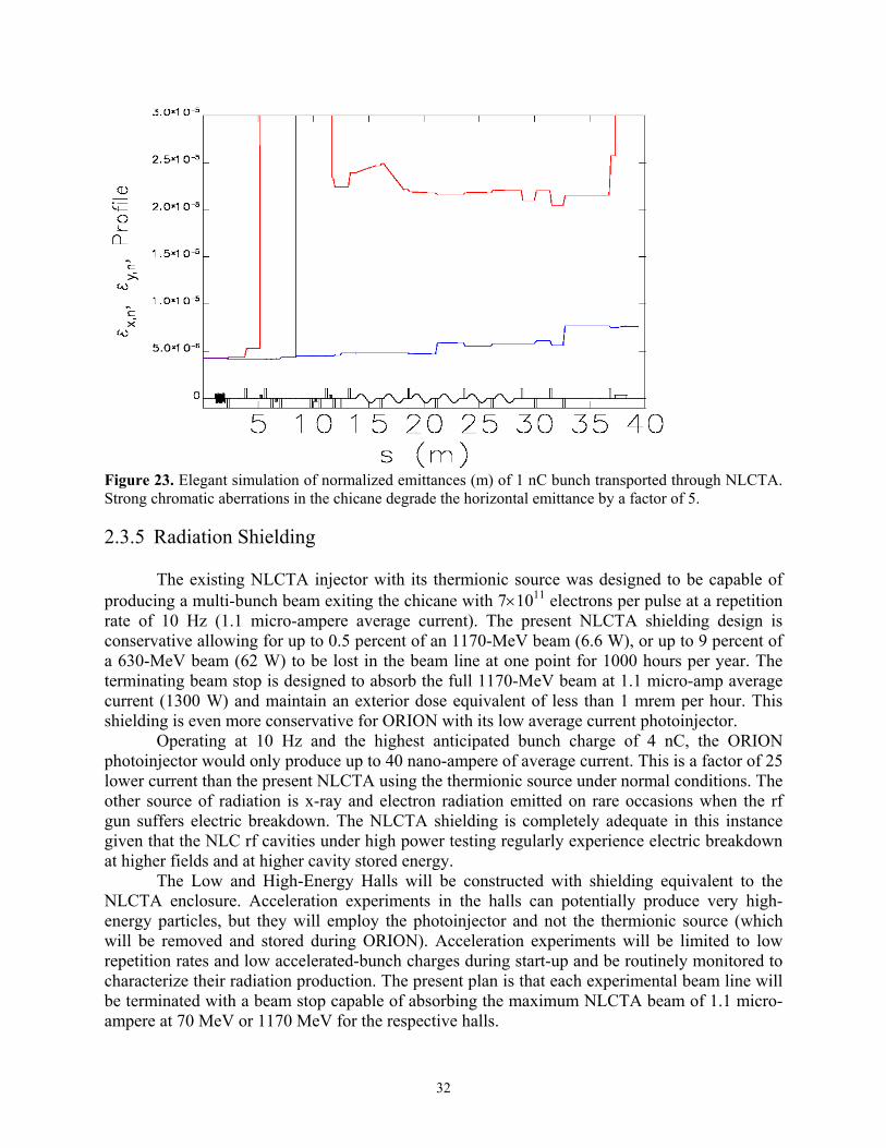
Figure 23. Elegant simulation of normalized emittances (m) of 1 nC bunch transported through NLCTA. Strong chromatic aberrations in the chicane degrade the horizontal emittance by a factor of 5.
2.3.5 Radiation Shielding
The existing NLCTA injector with its thermionic source was designed to be capable of producing a multi-bunch beam exiting the chicane with 7×10¹¹ electrons per pulse at a repetition rate of 10 Hz (1.1 micro-ampere average current). The present NLCTA shielding design is conservative allowing for up to 0.5 percent of an 1170-MeV beam (6.6 W), or up to 9 percent of a 630-MeV beam (62 W) to be lost in the beam line at one point for 1000 hours per year. The terminating beam stop is designed to absorb the full 1170-MeV beam at 1.1 micro-amp average current (1300 W) and maintain an exterior dose equivalent of less than 1 mrem per hour. This shielding is even more conservative for ORION with its low average current photoinjector.
Operating at 10 Hz and the highest anticipated bunch charge of 4 nC, the ORION photoinjector would only produce up to 40 nano-ampere of average current. This is a factor of 25 lower current than the present NLCTA using the thermionic source under normal conditions. The other source of radiation is x-ray and electron radiation emitted on rare occasions when the rf gun suffers electric breakdown. The NLCTA shielding is completely adequate in this instance given that the NLC rf cavities under high power testing regularly experience electric breakdown at higher fields and at higher cavity stored energy.
The Low and High-Energy Halls will be constructed with shielding equivalent to the NLCTA enclosure. Acceleration experiments in the halls can potentially produce very high-energy particles, but they will employ the photoinjector and not the thermionic source (which will be removed and stored during ORION). Acceleration experiments will be limited to low repetition rates and low accelerated-bunch charges during start-up and be routinely monitored to characterize their radiation production. The present plan is that each experimental beam line will be terminated with a beam stop capable of absorbing the maximum NLCTA beam of 1.1 micro-ampere at 70 MeV or 1170 MeV for the respective halls.
32

3 Facility Components
3.1 Overview
The ORION Facility will be constructed in the environs of SLAC End Station B (ESB) at the existing NLCTA. A plan view of the facility is shown in Figure 1. The layout of technical components will be shown in detail in a SLAC Drawing, “ORION Technical Installation Master Layout”, to be produced prior to construction start. The key modifications to the NLCTA are the ORION photoinjector with its S-band rf system, UV laser and laser room, a 1600 square-foot, low-energy experimental hall (north side), an 800 square-foot laser room for user’s and a 1000 square-foot, high-energy experimental hall (east side; upgradeable to 5000 square feet in the future if necessary). Laser rooms and experimental halls will be interlocked, and the latter will have redundant, movable beam stops at the beam entrance and fixed, terminating beam stops at the end of experimental lines. Adequate water and power utilities already exist at ESB for ORION and only new distribution from electrical breakers and water mains is required. In the following sections, we describe the various technical components of the ORION Facility.
3.2 RF Photoinjector
The electrical and mechanical fabrication techniques for the S-band BNL/SLAC/UCLA rf photoinjector are well understood today given that several such devices have been constructed. The S-band photoinjector operates in the TM01,π-mode and is tuned to be resonant with the 2.856 GHz rf system. The cathode lies in the plane terminating the 0.6 cell, and the beam exits the photoinjector from the full cell (Fig. 24). This geometry places the cathode surface, and hence the electron bunch launched, in a high-field region (140 MV/m) in order to accelerate the electrons and rapidly reduce the deleterious space-charge forces. The 0.6 cell length introduces a third harmonic content to the cavity fields, which flattens the longitudinal electric field, reduces the cathode to iris field ratio and provides more rf focusing in the low-energy region. The 1.6 cell length is about 8.5 cm, making the structure’s π-mode phase velocity synchronous with a particle near the speed of light.
The computer code SUPERFISH (Ref. 13) was used to determine the electromagnetic field properties of this structure, adjust the mechanical dimensions and derive frequency scaling laws for the cavity machining. At the 140 MV/m axial accelerating field determined by the beam optics design, the photoinjector requires about 15 MW of peak power. Operating at the 10 Hz repetition rate and a 3 µsec rf pulse length, the average power dissipation is 450 W. Frequency stability requires a temperature regulated water cooling system to maintain the cavity temperature to within ±0.1 C of nominal. Waveguide coupling from the klystron source is through the outer wall of the photoinjector’s full cell. To remove the field asymmetry induced by this coupling port, a vacuum port is placed on the opposite side. Two tuners are placed orthogonal to these ports, and the entrance and exit ports for the laser are located halfway between the tuner and rf/vacuum planes (Fig. 25).
33

Figure 24. Cross sectional view of the 1.6 cell, S-band photoinjector.
Figure 25. Arrangement of transverse penetrations into the 1.6 cell, S-band photoinjector. The ORION source is a modified version of the prototype 1.6 cell photoinjector that is
presently installed at the BNL Accelerator Test Facility (ATF). The ORION version has eliminated the use of the helico-flex as a combined vacuum and rf seal. The cathode/half cell vacuum joint of the ATF injector has been replaced with a 6 inch OD, rotatable stainless steel conflat knife-edge flange. Continuity of the rf current paths on the other hand is satisfied using press fit point-to-point contact between the half cell OD surface and the cathode plate edge. The edge of the cathode plate is Ti:N coated to facilitate cathode plate removal after high-temperature bake-out.
This arrangement allows for cathode inserts made of different materials to be retrofitted to the plate. Present photoinjectors use either metal cathodes such as copper and magnesium, or semiconducting materials such as cesium–telluride and gallium arsenide. Choosing an appropriate material is complicated by the fact that the environment under which the cathode operates involves ultra-high vacuum (10-9 Torr) and 100 MV/m fields. Cathode choice is a compromise between high quantum efficiency (electrons per photon), long lifetime, modest vacuum requirements, ease of material and surface preparation, work function comparable with available laser energies, and compatibility with high electric fields. A magnesium cathode was chosen for the baseline design because this material has operated successfully for many years at both the BNL-ATF and Argonne APS. Its quantum efficiency is at least an order of magnitude
34

greater than copper, insuring that there is a large margin in laser pulse energy for achieving the 0.25 nC design charge. Table 8 summarizes the design parameters for the ORION photoinjector.
Table 8. RF Photoinjecter Parameters
Frequency 2.856 GHz Acceleration Gradient 140 MV/m Cavities 1.6 cells Structure Fill Time 0.7 µsec Cathode Magnesium Quantum Efficiency 5×10⁻⁴ Design Bunch Charge 0.25 nC, optimum Charge Stability ±2.5%, pulse-to-pulse Beam Output Energy 7 MeV Energy Spread 0.8%, rms Nominal Bunch Length 1.8 psec, rms Bunch Timing Jitter 0.25 psec, rms Normalized Emittance ≤2×10⁻⁶ m, rms RF Input Peak Power 15 MW RF Repetition Rate 10 Hz RF Pulse Length 3 µsec Average Dissipated Power 450 W
The 1.6-cell body is composed of OFE II (oxygen-free, high-conductivity, grade II)
copper. Internal dimensions are machined to enforce field balance at the π-mode (i.e, the ratio of the peak accelerating field in the full-cell is equal to the cathode field in the half-cell). After final tuning of the full cell, the first hydrogen-braze step joins the full and half cells using 35%-65% gold-copper alloy (1025 C). After this braze, a cut-and-measure technique is used for the final half-cell tuning. Once the rf coupling, balanced field and π-mode tuning to 2.856 GHz is achieved, the second and final braze with 50%-50% gold-copper alloy (982 C) is performed.
The other essential element of the rf photoinjector is the emittance-compensation, solenoid magnet. The axial magnetic field and effective magnetic length needed to minimize the transverse emittance at the design charge come from the beam optics design described in Section 2.3.2. The computer code POISSON (Ref. 13) is used to design the solenoid. The electrical and mechanical parameters of the solenoid are given in Table 9.
Table 9. Solenoid Parameters
Nominal Axial Field 3 kG Magnetic Material 1006 Steel Conductor Copper, hollow Cross Section 0.395 cm2 Resistance 0.086 Ω Voltage 18.95 V Power 3445 W Current 220 A Current Density 557A/cm2
35

Figure 26. Schematic diagram of the ORION S-band, 1.6 cell photoinjector with emittance-compensation solenoid and diagnostics section.
A diagnostics section for measuring the beam exiting the photoinjector follows the solenoid and is mounted to the photoinjector girder. Figure 26 is a complete diagram of the photoinjector, solenoid and diagnostics section. A single diagnostic must span many orders of magnitude in dynamic range to be useful to operators of the ORION injector. The electron beam charge is expected to vary from 2 pC to 4 nC, and the bunch length from 150 fsec to 10 psec. The beamline distance of 150 cm from the cathode plate to the middle of the input coupler of the first of two X-band, 0.9 meter accelerating structures is determined by beam dynamics considerations (Sec. 2.3.2). In this limited space the rf gun, emittance compensation magnet, and low-energy photoinjector diagnostics must be placed. The injector region of the ORION Facility is shown in Figure 2. The suite of diagnostics must measure on a single-pulse basis the electron beam’s charge, energy, spot size, bunch length, position, and emittance. Also beam steering and vacuum pumping must be accomplished here. To fully utilize the limited space, all vacuum joints in the injector rf gun region will consist of a rotatable/non-rotatable, UHV knife-edge joint pair with one of the flanges having tapped bolt holes. This will eliminate the need for the addition of space during the nut/bolt installation and tightening process.
The bore of the emittance compensation magnet houses three components: 1) the solenoid magnet, 2) cos(θ) dipole steering magnets and 3) a Beam Position Monitor (BPM). Using the cos(θ) dipole steering magnet and a down stream profile screen, the electron beam energy will be measured directly out of the photoinjector, but prior to the X-band accelerating section.
36

Immediately after the emittance compensation magnet, a single arm of a non-magnetic, stainless steel, six-way port will be utilized as a multifunction assembly with phosphorus screen, aerogel cell, pepper pot emittance measuring device and Faraday cup for charge measurement. In addition, a second arm will be used for an ion pump/vacuum assembly. A pair of X & Y dipole steering magnets will also be located here. All profile screens will have a set of fiducial marks in the field of view of its CCD (charge coupled device) camera. This will permit self-calibration during normal operation. Each CCD camera will have a remotely controlled light-source for illumination during alignment and calibration. In addition all CCD cameras used for injector alignment and calibration will be slaved to a master control system capable of recording and redirecting input data to various monitors located throughout the ORION Facility on demand.
A second six-way port will also be utilized as both a diagnostics and vacuum port. An arm of the second diagnostics six-way port contains a phosphorus screen, aerogel cell and Faraday cup. In combination with the pepper-pot of the first six-way port, the aerogel cell of the second six-way port, light-transport system and the Hamamatsu streak camera, the ORION Facility will have a state-of-the-art slice emittance measurement diagnostic. An optical transport system will send light from the injector diagnostics region to Laser Room 1 for analysis. In addition, a third arm of the second diagnostics port will be allocated to a nearly normal incident UV laser transport mirror. This mode of laser transport is not anticipated for initial operation of the ORION photoinjector, but it is included in the design to facilitate different laser transport schemes in the future. A third pair of X&Y dipole steering magnets will provide final steering into the 0.75 cm aperture of the X-band accelerating sections.
Located in between the two diagnostic six-way ports described above is a ceramic break for a gap monitor and an integrating current transformer (ICT). The two Faraday cups and the single ICT allows for redundant charge measurements in the drift space between the rf gun and the first of the two 0.9 meter X-band sections. Just before the entrance of the 0.9 meter, X-band accelerating sections, a UHV gate valve and vacuum transfer box allow for a relatively simple and fast disconnect of the RF photoinjector for occasional maintenance. By bringing up to air only a small section of drift space, this scheme will prevent exposing the ORION electron source or X-band linacs to any significant amount of gas.
3.3 Drive Laser System
The drive laser supplies the photons that are absorbed by electrons in the photoinjector cathode, allowing these to escape the surface if their kinetic energy exceeds the material’s work function. The energy per laser pulse U(J) needed to produce a bunch of charge q(C) using photons of energy E(eV) (≥ work function = 3.6 eV for Mg) incident on a cathode surface with quantum efficiency QE (electrons emitted per incident photon) is given by U(J) = q(C)E(eV)/QE. A cathode’s QE depends on many conditions, and variations by a factor of two or more are common (Ref. 23). Assuming a conservative QE = 5×10⁻⁴ for magnesium (Ref. 7, 8) and 5 eV incident UV photons, only 10-5 J would be required to produce a 1 nC bunch under ideal conditions. Laser light will be absorbed by the various optical elements needed for pulse shaping as well as the elements needed for light transport to the photocathode. An estimated light-loss budget is needed to specify the design laser energy.
37

Based on experience with other ultraviolet drive lasers, a preliminary layout of the ORION laser system and transport line to the photocathode was made to derive an estimated light-loss budget. The laser light is transported about 75 feet from the laser room to the rf gun (Figs. 5 and 10). The light-loss estimate is given in Table 10. The first two entries give the maximum losses due to IR pulse masking prior to entering the frequency-tripling harmonic converter. All entries following the converter refer to transport of the UV light to the photocathode. Multiplying all the efficiencies in the last column of Table 10 yields an overall efficiency of IR to UV delivered to the cathode of 0.0078.
Table 10. Estimated Light-Loss Budget for the ORION Drive Laser System
Element Loss per Element Quantity Total Efficiency Fourier LCD Mask (IR) 0.10 1 0.90 Spatial LCD Mask (IR) 0.10 1 0.90 Harmonic Converter (IR to UV) 0.90 1 0.10 Grating 0.25 1 0.75 Cylindrical Lens 0.10 1 0.90 Mirror 0.02 15 0.74 Aperture 0.65 1 0.35 Polarizer 0.05 1 0.95 Lens 0.02 15 0.74 UHV Optical Port 0.08 3 0.78
A commercial Titanium-Sapphire (Ti:Sapphire) laser system planned for ORION is described here, and its parameters are given in Table 11. A block diagram of the conceptual laser system is shown in Fig. 27. A diode-pumped, green laser pumps a Ti:Sapphire oscillator delivering 2 psec pulses at 80 MHz with a wavelength selectable from 720 to 850 nm (IR). An Nd:YAG pumped Ti:Sapphire regenerative amplifier produces ten individual pulses per second over a wavelength range of 750 to 840 nm and up to a pulse IR energy of 10 mJ. After any spatial and Fourier masking for pulse shaping, these pulses are frequency-tripled in two nonlinear crystals to a wavelength of 266 nm (UV). Depending on the amount of IR masking, the UV energy arriving at the photocathode is expected to be 0.07 to 0.1 mJ. For magnesium, this is at least thirty times the energy needed for the nominal 0.25 nC charge. Bunch charges of 1 nC and higher are feasible with this large margin, and the system will be designed to allow a straightforward upgrade in the IR energy if necessary for future experiments.
Table 11. Drive Laser System Parameters
Laser Type Ti:Sapphire Output Wavelength 266 nm IR Energy (λ ≈ 800 nm) 10 mJ (no masking) UV Output Energy 1 mJ UV Amplitude Jitter ±2.5%, pulse-to-pulse Pulse Number 1 or 2 (split energy) Nominal Pulse Length 6.3 psec FWHM (Gaussian) Timing Jitter 0.25 psec, rms Macro-pulse Rep. Rate 10 Hz Cathode Spot Diameter 0.63 mm (flat-top) Laser Incidence on Cathode 72 deg. from normal
38

To minimize the energy spread of the electron beam, the laser pulse length should be short compared to the rf wavelength, or less than 2.5 psec, rms (10 degrees at 11.4 GHz). A pulse stretcher/compressor consisting of a pair of matched gratings allows for control of the nominally 6.3 psec pulse length (FWHM, Gaussian) for optimization of the electron bunch characteristics. Laser pulse length will be adjustable over a range of 150 fsec to 10 psec to accommodate different experimental requirements. To satisfy the timing jitter for electron bunch arrival at the X-band accelerator of 0.25 psec, the laser pulse must arrive at the cathode at a consistent phase relative to the rf accelerating field. The laser system is mode-locked to a harmonic of the photoinjector rf system and stabilized to deliver the laser pulse to within 0.25 psec, rms, or two degrees of rf phase at 11.4 GHz, for consistent bunch arrival timing. The laser amplitude in the UV must be stable to ±2.5%, pulse-to-pulse, in order to maintain the corresponding bunch charge stability from the photoinjector. In a frequency-tripled system, the IR amplitude stability must be one-third of this value or ±0.8%, pulse-to-pulse.
Figure 27. Block diagram of drive laser system for the ORION photoinjector.
39
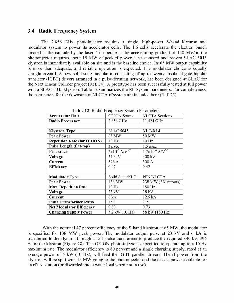
3.4 Radio Frequency System
The 2.856 GHz, photoinjector requires a single, high-power S-band klystron and modulator system to power its accelerator cells. The 1.6 cells accelerate the electron bunch created at the cathode by the laser. To operate at the accelerating gradient of 140 MV/m, the photoinjector requires about 15 MW of peak rf power. The standard and proven SLAC 5045 klystron is immediately available on site and is the baseline choice. Its 65 MW output capability is more than adequate, and reliable operation is expected. The modulator choice is equally straightforward. A new solid-state modulator, consisting of up to twenty insulated-gate bipolar transistor (IGBT) drivers arranged in a pulse-forming network, has been designed at SLAC for the Next Linear Collider project (Ref. 24). A prototype has been successfully tested at full power with a SLAC 5045 klystron. Table 12 summarizes the RF System parameters. For completeness, the parameters for the downstream NLCTA rf system are included here (Ref. 25).
Table 12. Radio Frequency System Parameters Accelerator Unit ORION Source NLCTA Sections Radio Frequency 2.856 GHz 11.424 GHz Klystron Type SLAC 5045 NLC-XL4 Peak Power 65 MW 50 MW Repetition Rate (for ORION) 10 Hz 10 Hz Pulse Length (flat-top) 3 µsec 1.5 µsec Perveance 2×10⁻⁶ A/V3/2 1.2×10⁻⁶ A/V3/2 Voltage 340 kV 400 kV Current 396 A 300 A Efficiency 0.47 0.42 Modulator Type Solid State/NLC PFN/NLCTA Peak Power 138 MW 238 MW (2 klystrons) Max. Repetition Rate 10 Hz 180 Hz Voltage 23 kV 38 kV Current 6 kA 12.5 kA Pulse Transformer Ratio 15:1 21:1 Net Modulator Efficiency 0.80 0.73 Charging Supply Power 5.2 kW (10 Hz) 88 kW (180 Hz)
With the nominal 47 percent efficiency of the S-band klystron at 65 MW, the modulator
is specified for 138 MW peak power. The modulator output pulse at 23 kV and 6 kA is transferred to the klystron through a 15:1 pulse transformer to produce the required 340 kV, 396 A for the klystron (Figure 28). The ORION photo-injector is specified to operate up to a 10 Hz maximum rate. The modulator efficiency is 80 percent and a single charging supply, rated at an average power of 5 kW (10 Hz), will feed the IGBT parallel drivers. The rf power from the klystron will be split with 15 MW going to the photoinjector and the excess power available for an rf test station (or discarded into a water load when not in use).
40

The rf power will be transferred to the photoinjector through an evacuated waveguide and pass through a circulator (for klystron protection from reversed power flow) prior to entering the NLCTA enclosure. Sulfur-hexafloride (SF-6) gas at 24 psi is used in the circulator to reduce electrical breakdown problems. The required field amplitude stability in the photoinjector is 1 percent. If the downstream linac were S-band, the phase stability would be the usual 1 degree or 1 psec (0.3 mm) at 2.856 GHz. But the photoinjector beam is transferred into an X-band accelerator, so the phase stability is actually 1 degree at 11.4 GHz, or 0.25 psec (0.075 mm).
C11100ufd 3kv
Grid
Emitter
GRN+15V
Collector
DRV1
IGBT DRIVER Q11
2 ea 3.3Kv 800A
C12
50ufd 400v
D11 8kv T11
1/1
C21100ufd 3kv
Grid
Emitter
GRN+15V
Collector
DRV21
IGBT DRIVER Q21
2 ea 3.3Kv 800A
C22
50ufd 400v
D21 8kv T21
1/1
C31100ufd 3kv
Grid
Emitter
GRN+15V
Collector
DRV31
IGBT DRIVER Q31
2 ea 3.3Kv 800A
C32
50ufd 400v
D31 8kv T31
1/1
C10100ufd 3kv
Grid
Emitter
GRN+15V
Collector
DRVn1
IGBT DRIVER Qn1
2 ea 3.3Kv 800A
Cn2
50ufd 400v
Dn1 8kv T10
1/1
Pulse Transformer
1/15
23 kV, 6.0 kA
3 usec0.007 V-Sec
23 kV6000 A
5045 KLYSTRON340 kV 396 A3 uS
10 CORE sections20 IGBT drivers
+
+
+
+
Figure 28. Block diagram of the S-band rf power system used for testing the NLC solid state modulator. A modified low repetition rate, low average power version will be used for ORION.
41

3.5 Transfer Lines
Extraction of beam for the Low-Energy Hall (7 to 67 MeV) occurs immediately after the chicane section of the NLCTA injector. The beam must be transported through the north shield wall. The shielding blocks for the walls and roof of the NLCTA enclosure are of a staggered-joint design for earthquake stability and radiation containment. With the substantial rf waveguide on the roof, disassembly of these blocks would be very difficult and expensive. Instead, a five-meter long, ten-centimeter diameter hole will be bored at a roughly 25-degree angle through the NLCTA shielding wall. Quadrupole magnet triplets will be used on either side of the wall to transport the beam (Figure 29). The separation between adjacent beamline centers in the Low-Energy Hall is about 8 feet to facilitate experimental installation and maintenance.
Figure 29. Conceptual drawing of the Low-Energy Transfer Line and beam lines in the Low-Energy Experimental Hall.
Extraction of beam for the High-Energy Hall (67 to 350 MeV) is done through the NLCTA spectrometer magnet (Figure 30). The NLCTA terminating beam stop will remain in place and two beam holes will be bored through it during the ORION civil construction. The angled hole will be plugged with steel so the spectrometer remains usable, but this hole will be available in the future if such a beamline is ever needed. Beam for the HE Hall passes straight ahead, and a new terminating beam stop will be installed at the end of the HE beamline. The entry beamlines for both experimental halls will each have two redundant, moveable beam stops, which when closed, will allow personnel access to the halls even when beam is enabled in the NLCTA enclosure. Only when the hall access doors are interlocked shut and both beam stops are held open actively will beam be enabled to enter the hall.
42
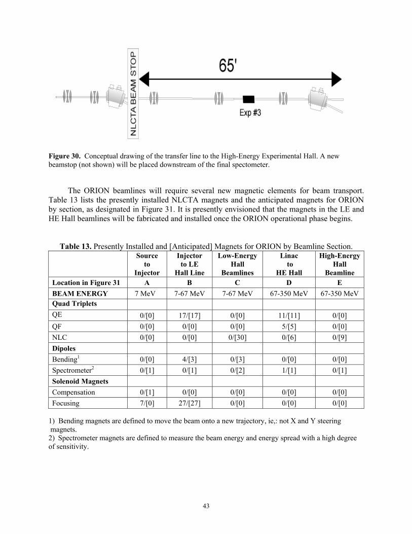
Figure 30. Conceptual drawing of the transfer line to the High-Energy Experimental Hall. A new beamstop (not shown) will be placed downstream of the final spectometer.
The ORION beamlines will require several new magnetic elements for beam transport. Table 13 lists the presently installed NLCTA magnets and the anticipated magnets for ORION by section, as designated in Figure 31. It is presently envisioned that the magnets in the LE and HE Hall beamlines will be fabricated and installed once the ORION operational phase begins.
Table 13. Presently Installed and [Anticipated] Magnets for ORION by Beamline Section.
Source
to Injector
Injector to LE
Hall Line
Low-Energy Hall
Beamlines
Linac to
HE Hall
High-Energy Hall
Beamline Location in Figure 31 A B C D E BEAM ENERGY 7 MeV 7-67 MeV 7-67 MeV 67-350 MeV 67-350 MeV Quad Triplets QE 0/[0] 17/[17] 0/[0] 11/[11] 0/[0] QF 0/[0] 0/[0] 0/[0] 5/[5] 0/[0] NLC 0/[0] 0/[0] 0/[30] 0/[6] 0/[9] Dipoles Bending1 0/[0] 4/[3] 0/[3] 0/[0] 0/[0] Spectrometer2 0/[1] 0/[1] 0/[2] 1/[1] 0/[1] Solenoid Magnets Compensation 0/[1] 0/[0] 0/[0] 0/[0] 0/[0] Focusing 7/[0] 27/[27] 0/[0] 0/[0] 0/[0]
1) Bending magnets are defined to move the beam onto a new trajectory, ie,: not X and Y steering magnets. 2) Spectrometer magnets are defined to measure the beam energy and energy spread with a high degree of sensitivity.
43

Figure 31. Relative positions of the NLCTA/ORION beamlines as referred to in Tables 13 and 14. Distances are not to scale.
3.6 Diagnostics
ORION operations and experiments will require instrumentation for measuring the position, energy, transverse size, length, spacing and intensity of electron bunches. In many cases where bunch characteristics are similar to those in the present NLCTA, standard beam position monitors (BPM), profile monitors, wire scanners, toroid intensity monitors, wall current monitors, bunch length monitors, bunch spacing monitors and Faraday cups will be used. There are special beam diagnostics for the photoinjector, and these were described in Section 3.2. There are also some special beam diagnostics in the final transfer lines leading to the experimental halls, which are required to resolve the ultra-short and/or low-emittance bunches prior to delivery to the users. Note from Table 2 that a large range of longitudinal and transverse emittances as well as bunch charge (pico to nano-Coulombs) will need to be measured at entry to the experimental halls. Table 14 summarizes the diagnostics presently installed in NLCTA and those anticipated for ORION by section, as designated in Figure 31.
Diagnostics for bunch charge, position, spot size, emittance, temporal length and energy spectrum will all be required to configure the machine for each user's needs. Diagnostic design is complicated by the desire to measure beam properties in two distinct ranges: (1) "Nominal charge, single bunch" mode with 0.25 to 4.0 nC charge, and (2) "Low charge, single bunch" mode with 2 to 20 pC charge. As such, some of the existing diagnostics at the NLCTA will need either modifications made to increase sensitivity, decrease response time, or both.
Temporally integrating diagnostics, such as the fluorescent screens and Faraday cups in NLCTA, view the thermionic source’s long macropulse as a single bunch with ~100 nC charge. If one intends to also monitor the low-charge single bunch with these same diagnostics, the dynamic range requirement is severe at nearly 50dB. Variable attenuators can be used ahead of readout electronics for BPMs, toroids, and Faraday cups to expand the dynamic range provided that the readout electronics have sufficient sensitivity. Profile monitor cameras, however, will have to be augmented by intensified cameras to view the lowest charge bunches. Changing all charge injection device (CID) cameras presently installed and planned is too expensive, so it is proposed that only two or three key profile monitors be instrumented with intensified cameras, and that tune-up for the low-charge, single bunch mode begin with a tune-up with modest charge
44

(e.g. 100 pC) that gives clear signals on all diagnostics, followed by a gradual reduction in charge (by reducing the radius of the laser spot on the cathode, holding the laser pulse energy constant so as to preserve the bunch focusing properties) while monitoring the intensified profile monitors and readjusting the focusing as needed.
Table 14. Presently Installed and [Anticipated] Diagnostics for ORION by Beamline Section.
Source
to Injector
Injector to LE
Hall Line
Low-Energy Hall
Beamlines
Linac to
HE Hall
High-Energy Hall
Beamlines Location in Figure 31 A B C D E BEAM ENERGY 7 MeV 7-67 MeV 7-67 MeV 67-350 MeV 67-350 MeV Integrating Current Transformer 0/[1] [3] [6] 3 [2]
Faraday Cup 0/[2] 0 [3] 1 [1] NLCTA Fluorescent Screen 0/[2] 1/[2] [15] 4 [4]
NLCTA Wire Scanner 0 1 0 2 0 OTR Screen [2] [1] [4] 0/[1] [2] NLCTA BPM [1] 19 [6] 17 [2] Pepper Pot 0/[1] 0/[1] 0 0 0 Bunch Length Monitor [1] 1 0 0/[1] 0 Spectrometer [1] 0/[1] [2] 1 [1]
Emittance measurement by the quadrupole magnet scan/three-screen technique is
sufficient for most cases once the beam energy is 50 MeV or higher. For the special high-density, low-energy beams produced by the rf photoinjector, however, emittance-mask techniques must be used. A “pepper pot” is planned for the ~1 meter beamline section immediately following the photoinjector to facilitate tune-up. A second pepper pot mask installed before the chicane is also desirable as it would give a convenient comparison measurement to use against the quadrupole scan technique.
Longitudinal phase space measurements are confined to energy spectrum in dispersive regions of the beamline, to beam current spectral content measurements at ceramic gaps, and to direct profile measurement with a “prompt” radiator (e.g. Cerenkov or optical transition radiation (OTR)) examined by a streak camera. Energy spectrum measurements are not confined to the ends of the experimenter’s beamlines, where spectrometers are placed, but may also be done using the extraction “doglegs” at both the low-energy and high-energy extraction lines by placing profile monitors at suitable locations within the transport lines. High-frequency measurement of beam current spectra provides information about the approximate rms bunch length that is valuable in tuning the accelerating section phases and chicane dispersion, and desirable not only in the injector (as presently installed) but at the exit of the chicane, and again at the exit of the last accelerator section. Direct profile measurement by streak camera is envisaged during the source-commissioning phase to occur immediately after the photoinjector, and subsequently at the locations of the experiments themselves.
45

3.7 Conventional Facilities
3.7.1 Laser Rooms
The photoinjector’s cathode is driven by the Ti:Sapphire laser described in Section 3.3. For ease of operation and maintenance, this laser is to be located outside the NLCTA concrete tunnel enclosure, but within End Station B. A location at the northeast corner of ESB and east of the new NLC 8-Pack rf test station, as shown in Fig. 5, is presently planned. The room will be called Laser Room 1.
Purchase of a 500 square-foot commercial laser room with an entry-exit vestibule is envisioned. It should be a Class 10000 clean room and air-conditioned to achieve temperature stability above the optical table at the level of ± 1/2°C. Laser power supply and racks are to be located outside and adjacent to the laser room. A rack for the laser control system will be in the clean room to minimize the path length for cabling to the laser table. The room will be shielded from electromagnetic noise. Installation of the laser room will be through the dismountable block wall on the east side of ESB before that area is sealed off for construction of the Low Energy Hall.
A similar laser room as that for the photoinjector is required to house the lasers supporting the user experimental programs. This Laser Room 2 will be located between the Low Energy and High Energy Halls to reduce the light-path length (Fig. 1 and 5). This puts it outside the End Station B enclosure and will require added air-conditioning capacity to meet the temperature stability requirements, and a weather-tight building or shell needs to surround it. This laser room also must be Class 10000 and should be 20' × 40' with an entry-exit vestibule.
3.7.2 Experimental Halls
The Low Energy Hall (LEH) is presently conceived to have three separate beam lines split off from the primary transfer line by means of DC dipole magnets. The separation between adjacent beamline centers is about 8 feet to facilitate experimental installation and maintenance. The High Energy Hall will have one beamline initially. Experimental modules will be assembled and surveyed onto standard girders in a Staging Area (Sec. 3.7.3). These units are then moved to the appropriate experimental hall during scheduled change-overs. Floor rails and linear bearings will be used to eliminate much of the final surveys in place.
The LEH is to be located immediately east of Laser Room 1 and will extend beyond the east wall of ESB and north of the NLCTA shielding enclosure. Its interior dimensions are presently set at 34' × 48' ×10' high resulting in ~1600 ft2 of experimental area. The Hall will have one labyrinth-type entrance module complete with a personnel protection system (PPS) gate within ESB. If required an emergency exit physically separated from the entrance module will be included. Experimental equipment installation and removal is either via the entrance labyrinth or via a separate, normally closed off entrance using a movable wall shielding block(s). The wall thickness of the LEH enclosure is 6 feet. The roof block thickness is 5 feet. Roof beams are not meant to be removed once installed since they would support lighting, cable trays over the beam lines, 120V and 208V AC circuits with outlet boxes, and low-conductivity water (LCW) and gas lines. Wall blocks and roof blocks are patterned after the NLCTA staggered joint design shown in Figure 5 to prevent radiation escaping from cracks.
46

The High Energy Hall (HEH) is to be constructed adjacent to the east end of the NLCTA enclosure. The interior dimensions are roughly 15' wide × 65' long × 10' high resulting in about 1000 ft2 and is adequate for one beamline. A future expansion of the HE Hall to about 5000 ft2
(dimensions 39' wide × maximally 130' long × 10' high) is possible if the experimental program requires it. The HEH will have one labyrinth-type entrance module complete with a PPS gate. If required an emergency exit physically separated from the entrance module will be included. Large experimental equipment installation/removal is via special removable concrete wall shielding blocks. The wall thickness of the HEH is 6 feet. The concrete roof blocks are 5 feet thick and are not intended to be removed once installed. They will support lighting, cable-trays, 120V and 208V AC circuits, low-conductivity water (LCW) and gas lines. The concrete blocks are also patterned after the NLCTA blocks.
Presently it is envisioned that electron beam will enter the HEH via one trajectory straight through the NLCTA eastern end wall which houses the NLCTA terminating beam stop. The penetration will be generated by perforation of the beam stop. A new terminating beam stop will be installed at the end of the beam line in the HEH with appropriate additional local shielding. A second penetration at an angle determined by the existing NLCTA spectrometer dipole magnet will also be made during the ORION civil construction phase. This hole will be filled with steel so as to maintain use of the spectrometer and beam stop, but the penetration will be available if a future experimental program requires it.
3.7.3 Staging and Construction Areas
The ORION Facility will require space for staging of experimental hardware before installation into the experimental halls. Assuming that at most four separate user groups would be on site, with experiments running or assembling on the four ORION beamlines, the present estimate is that roughly 3600 square-feet of total staging area is needed in or near the Central Research Yard. Specifically space will be needed for a high-bay assembly area (900 sq. ft.) with overhead crane coverage for experimental module preparation, a technician room and machine shop (900 sq. ft.), four separate user lab/storage rooms (1200 sq. ft.), a shared clean room (300 sq. ft.), and a Data Acquisition Room (300 sq. ft.) for users to monitor and run their experiments (Sec. 3.7.4). Also needed near the LEH/HEH is some modest amount of office space for the experimenters, be they users or SLAC staff. This office space could be in the research yard or elsewhere on the SLAC site.
Space for equipment preparation and storage will be needed during ORION construction. Presently, Accelerator Research Department B (ARDB) is using Building 102B which has a clean room with HEPA filters, an assembly space and is accessible by forklift. It is 35' × 40' ≡ 1400 ft2 of which 200 ft2 are dedicated to the clean room and 175 ft2 are office space. A 200 ft2 lab is adjacent to the main room. This building may be used during the ORION construction phase.
3.7.4 Data Acquisition Room
The NLCTA Control Room is presently dedicated to the operation and monitoring of the accelerator systems. It will be modified to include operator control of the ORION transfer lines. ORION users will require a separate Data Acquisition Room (DAQ Room) in the vicinity of the experimental halls for setting up their computers for experiment control and data taking.
47

A 300 square-foot (15' × 20') room would be adequate for this purpose. Data analysis and more general office usage are expected to take place in other user office space on the SLAC site. Users will locate hardware specific for controlling and acquiring data from their experiments in the DAQ room, which will be equipped with computer consoles for controlling beamline magnets immediately adjacent to the experiments, and for reading beamline magnet configurations and diagnostics. The DAQ room will be connected to the experimental halls and laser rooms via dedicated signal-only cable trays, and will have access to the full complement of trigger and timing signals used in running the accelerator. Communication via telephone and intercom with the interior of the shielding enclosures, laser rooms, NLCTA main control room, and the Main Control Center of SLAC will be established.
3.7.5 Utilities and Services
The ORION Facility will require LCW water, compressed house air, 120V and 208V AC circuits and outlets, air-conditioning, specialty-gas lines, and lighting. The LCW needs are modest to cool the small dipole switcher magnets, spectrometer dipole magnets, the photoinjector, its laser and rf system. All the quadrupoles and corrector magnets have air-cooled solid conductor coils. An electrical power and water-cooling estimate has been made for ORION at End Station B showing that 144 kW of power and 256 GPM of LCW water are needed in total (Table 15). This does not include the Staging Area, DAQ Room or contingency. End Station B and specifically NLCTA have enough AC and LCW capacity to satisfy all the envisioned ORION Facility requirements. Water headers will have to be brought into the LEH and HEH originating at the NLCTA and 8-Pack Station main headers. The AC circuits will come from a spare breaker in the 3 MW sub-station south of ESB, which also serves NLCTA. Air-conditioning of Laser Room 1 and Laser Room 2 will be procured as part of the commercial room construction. Air-conditioning, if any, of the LEH/HEH is still under discussion.
Table 15. Estimated ORION Utility Requirements
Area Electrical Load (kW)
Air Heat Load (kW)
Water Heat Load (kW)
Water Flow (GPM)
Laser Rm. 1 internal 3.7 3.8* 0 0 Laser Rm. 1 external 13.1 5.1 11.7 55 RF Photoinjector 7 1 6.5 30 Modulator System 10.7 2.5 0.5 2 Klystron System 1 1 7.2 35 Laser Rm. 2 internal 7.2 7.5* 0 0 Laser Rm. 2 external 26.3 10.2 23.3 110 LE Hall internal 1.8 10 24 6 LE Hall external 37.2 5 0 6 HE Hall internal 1.5 6.7 24 6 HE Hall external 34.2 5 0 6 Total Loads 143.7 46.5 97.2 256
* These air heat loads are absorbed by the HVAC water-cooled units external to the laser rooms.
48

3.8 Control Systems
The ORION Facility control system will be integrated seamlessly into the present NLCTA control system, which is based on the SLC control system. The SLC VAX computer controls monitor the machine though a series of distributed microprocessors, which in turn control individual beam line components via CAMAC. The topology of the system is a logical star network with the Host machine coordinating geographically distributed slave microprocessor clusters. ORION will ‘appear’ to the SLC control system as one more microprocessor cluster. The ORION microprocessor cluster will be in parallel to NLCTA. The advantage of this arrangement is that software and hardware that have been extensively tested on all accelerators in the SLAC complex can be utilized.
The SLC control system is designed to allow the use of multiple independent control consoles. Full function control consoles consisting of a touch panel, graphics monitor and slew knobs exist in the NLCTA control room. Personal computer-based terminals capable of running X-windows are also available to use as a control system interface. Experimenters can use these terminals to run commercially available software, such as LabView, to control and record their individual experiments data. The SLC interface used by E-157 and E162 will be used to date stamp the ORION machine parameters to correlate experimental results to machine parameters.
3.9 Protection Systems
The protection systems are divided into three groups. The Beam Containment System (BCS) will insure that the confinement integrity of the beam line housing is not violated by large excursions of the beam from its nominal trajectory. The Personnel Protection System (PPS) will insure the safety of personnel in and around the NLCTA and ORION beam line housings by controlling access to the housings, by providing emergency-off controls, and by monitoring radiation levels via Beam Shutoff Ion Chambers (BSOIC). Any PPS or BCS violation will result in the inhibiting of redundant permissions to the associated systems. Finally, the Machine Protection System (MPS) will provide for the protection of beam line components and inhibit permissions to the associated systems in the event of a violation.
Because the ORION Facility is derived from modifications and additions to the existing NLCTA, the ORION protection systems will be extensions of these and integrated into the existing protection systems consistent with present ESH requirements at SLAC. The only novel introduction is the need to have the safety interlock system for the laser rooms and experimental halls designed to allow access to these when the two redundant beam stops are in place and particle beam is enabled in the linac enclosure. Beam can only enter the experimental halls when the hall doors are interlocked shut and the redundant beam-stops are actively maintained in an open state. Also, for laser set-up and calibration, it is necessary to have access to the NLCTA enclosure and experimental halls when a laser is operational provided that appropriate personal protection equipment is in use.
The main X-band linac will be protected from catastrophic vacuum failure through the use of a commercially available fast acting vacuum isolation system. Individual detectors will be used to sense pressure increases on the transfer lines into HE and LE Halls. Slower, remotely controlled isolation valves will back up the fast valves. The location of the detectors and isolation valves will be chosen in such a way to protect the photoinjector along with the X-band linac sections from vacuum failure in either the LE or HE Halls.
49

Acknowledgements The Technical Design Study for the ORION Research Facility, presented in this document, is the result of the contributions of many scientists, engineers, designers and support staff at Stanford University, Stanford Linear Accelerator Center, the University of California at Los Angeles, and the University of Southern California, working under the direction of the ORION project management team at SLAC.
This work is supported by the U.S. Department of Energy under contract DE-AC03-76SFO0515.
References
1. See for example, the Proc. of the Ninth Advanced Accelerator Conference, Santa Fe, New Mexico, June 2000 (to be published by American Physical Society, New York).
2. ORION: An Accelerator Research Facility at SLAC, SLAC internal report, July 1999 (included as an appendix in Ref. 5).
3. NLCTA Conceptual Design Report, SLAC-Report-411, August 1993. 4. The NLC 8-Pack Project, at http://www-project.slac.stanford.edu/lc/local/Projects/8Pack/8Pack.html. 5. The ORION Workshop, February 23-25, 2000. See the workshop report at http://www-
project.slac.stanford.edu/orion. 6. “Laser Acceleration in Vacuum”, SLAC proposal E163, September 2001. 7. D.T. Palmer, “The Next Generation Photoinjector”, Stanford Univ. Thesis, 1998. 8. E.R. Colby, “Design, Construction and Testing of a Radiofrequency Electron
Photoinjector for the Next Generation Linear Collider”, UCLA Thesis, 1997. 9. M. Ferrario et al, “HOMDYN Study for the LCLS Photoinjector”, presented at the 2nd
ICFA Advanced Accelerator Workshop on the Physics of High Brightness Beams, Nov. 9-12, 1999, Univ. of California, Los Angeles.
10. L. Serafini and J.B. Rosenzweig, “Envelope Analysis of Intense Relativistic Quasi-Laminar Beams in RF Photoinjectors: A Theory of Emittance Compensation”, Phys. Rev. E, Vol. 55, pp.7565-7590 (1997).
11. J. Rosenzweig and E. Colby, “Charge and Wavelength Scaling of RF Photoinjector Designs” in the Proc. of the 1994 Adv. Accel. Conf., AIP Proc. No. 335, pp. 724-737 (1995).
12. L. Young et al, PARMELA version 3, LA-UR-96-1835, revised Dec. 4, 2000. 13. K. Halbach and R.F. Holsinger, “SUPERFISH - A Computer Program for Evaluation of
RF Cavities with Cylindrical Symmetry”, Particle Accelerators, Vol. 7, pp. 213-222 (1976). This program package also contains POISSON.
14. B. Carlsten and D.T. Palmer, “Enhanced Emittance Compensation in a High-Frequency RF Photoinjector using RF Radial Focusing”, Nucl. Inst. Meth. A425, pp. 37-50 (1999).
15. S.G. Anderson and J.B. Rosenzweig, “Nonequilibrium Transverse Motion and Emittance Growth in Ultrarelativistic Space-Charge Dominated Beams”, Phys. Rev. ST – Accel. and Beams, Vol. 3, 094201 (2000).
16. T. Katsouleas, Phys. Rev. A 33, 2056-2064 (1986).
50
51
17. J.B. Rosenzweig, B. Breizman, T. Katsouleas, and J.J. Su, Phys. Rev A 44, R6189-R6192 (1991).
18. N. Barov, et al, Phys. Rev. ST Accel. Beams 3, 011301 (2000). 19. SLAC Proposal E163, “Response to Questions of the Experimental Program Advisory
Committee”, March 11, 2002. 20. W. Graves, “Sub-picosecond measurements of photoinjector electron beam properties”,
talk presented at the LCLS TAC meeting, SLAC, December, 2001. 21. C. Adolphsen, SLAC, Transport input file dated May 12, 1995. 22. NLC ZDR, SLAC-474, May, 1996. 23. W.J. Brown, et al, “Low Emittance Electron Beam Formation with a 17 GHz RF Gun”,
MIT, January 2001, submitted for publication. 24. A. Donaldson and R. Cassel, SLAC, private communication. 25. C. Adolphsen, SLAC, private communication.