Embed Size (px)
Citation preview
OrionTelescopes.comCustomer Support (800) 676-1343E-mail: [email protected] Offices (831) 763-700089 Hangar Way, Watsonville, CA 95076Providing Exceptional Consumer Optical Products Since 1975
Orion Atlas™ Pro AZ/EQ-G GoTo Mount
#10010
IN 479 Rev. A 02/13
inSTruCTiOn MAnuAl
2
Congratulations on your purchase of the Orion Atlas Pro AZ/EQ-G GoTo
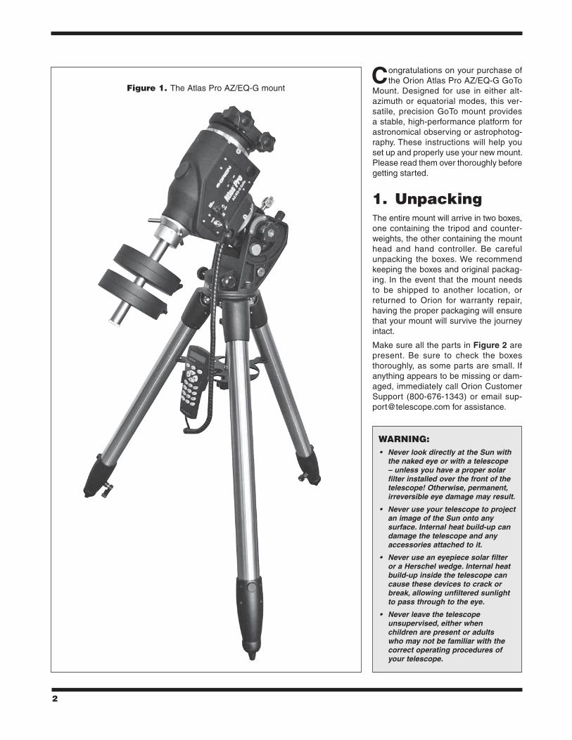
Mount. Designed for use in either alt-azimuth or equatorial modes, this ver-satile, precision GoTo mount provides a stable, high-performance platform for astronomical observing or astrophotog-raphy. These instructions will help you set up and properly use your new mount. Please read them over thoroughly before getting started.
1. unpackingThe entire mount will arrive in two boxes, one containing the tripod and counter-weights, the other containing the mount head and hand controller. Be careful unpacking the boxes. We recommend keeping the boxes and original packag-ing. In the event that the mount needs to be shipped to another location, or returned to Orion for warranty repair, having the proper packaging will ensure that your mount will survive the journey intact.
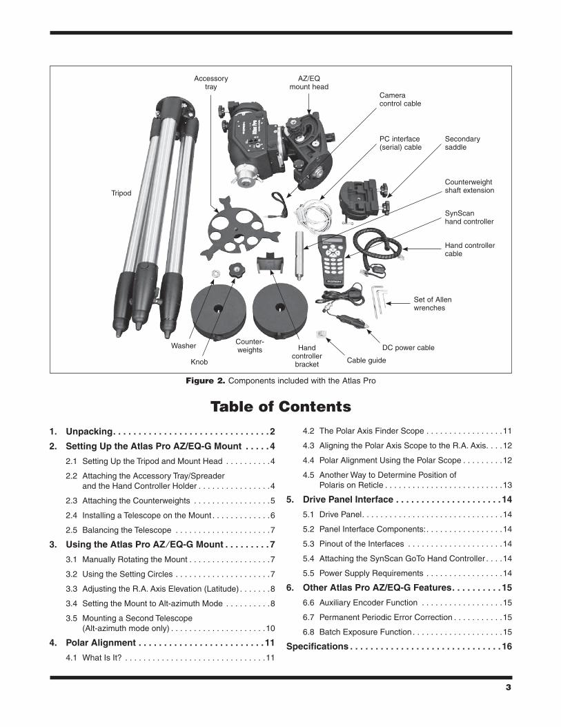
Make sure all the parts in Figure 2 are present. Be sure to check the boxes thoroughly, as some parts are small. If anything appears to be missing or dam-aged, immediately call Orion Customer Support (800-676-1343) or email [email protected] for assistance.
Figure 1. The Atlas Pro AZ/EQ-G mount
WArninG: • NeverlookdirectlyattheSunwith
thenakedeyeorwithatelescope–unlessyouhaveapropersolarfilterinstalledoverthefrontofthetelescope!Otherwise,permanent,irreversibleeyedamagemayresult.
• NeveruseyourtelescopetoprojectanimageoftheSunontoanysurface.Internalheatbuild-upcandamagethetelescopeandanyaccessoriesattachedtoit.
• NeveruseaneyepiecesolarfilteroraHerschelwedge.Internalheatbuild-upinsidethetelescopecancausethesedevicestocrackorbreak,allowingunfilteredsunlighttopassthroughtotheeye.
• Neverleavethetelescopeunsupervised,eitherwhenchildrenarepresentoradultswhomaynotbefamiliarwiththecorrectoperatingproceduresofyourtelescope.
3
Table of Contents
1. Unpacking. . . . . . . . . . . . . . . . . . . . . . . . . . . . . . . 2
2. Setting Up the Atlas Pro AZ/EQ-G Mount . . . . . 4
2.1 Setting Up the Tripod and Mount Head . . . . . . . . . .4
2.2 Attaching the Accessory Tray/Spreader and the Hand Controller Holder . . . . . . . . . . . . . . . .4
2.3 Attaching the Counterweights . . . . . . . . . . . . . . . . .5
2.4 Installing a Telescope on the Mount . . . . . . . . . . . . .6
2.5 Balancing the Telescope . . . . . . . . . . . . . . . . . . . . .7
3. Using the Atlas Pro AZ ⁄ EQ-G Mount . . . . . . . . . 7
3.1 Manually Rotating the Mount . . . . . . . . . . . . . . . . . .7
3.2 Using the Setting Circles . . . . . . . . . . . . . . . . . . . . .7
3.3 Adjusting the R.A. Axis Elevation (Latitude) . . . . . . .8
3.4 Setting the Mount to Alt-azimuth Mode . . . . . . . . . .8
3.5 Mounting a Second Telescope (Alt-azimuth mode only) . . . . . . . . . . . . . . . . . . . . .10
4. Polar Alignment . . . . . . . . . . . . . . . . . . . . . . . . . 11
4.1 What Is It? . . . . . . . . . . . . . . . . . . . . . . . . . . . . . . .11
4.2 The Polar Axis Finder Scope . . . . . . . . . . . . . . . . .11
4.3 Aligning the Polar Axis Scope to the R.A. Axis. . . .12
4.4 Polar Alignment Using the Polar Scope . . . . . . . . .12
4.5 Another Way to Determine Position of Polaris on Reticle . . . . . . . . . . . . . . . . . . . . . . . . . .13
5. Drive Panel Interface . . . . . . . . . . . . . . . . . . . . . 14
5.1 Drive Panel. . . . . . . . . . . . . . . . . . . . . . . . . . . . . . .14
5.2 Panel Interface Components:. . . . . . . . . . . . . . . . .14
5.3 Pinout of the Interfaces . . . . . . . . . . . . . . . . . . . . .14
5.4 Attaching the SynScan GoTo Hand Controller . . . .14
5.5 Power Supply Requirements . . . . . . . . . . . . . . . . .14
6. Other Atlas Pro AZ/EQ-G Features. . . . . . . . . . 15
6.6 Auxiliary Encoder Function . . . . . . . . . . . . . . . . . .15
6.7 Permanent Periodic Error Correction . . . . . . . . . . .15
6.8 Batch Exposure Function . . . . . . . . . . . . . . . . . . . .15
Specifications . . . . . . . . . . . . . . . . . . . . . . . . . . . . . . 16
Figure 2. Components included with the Atlas Pro
Camera control cable
PC interface (serial) cable
Secondary saddle
SynScan hand controller
Counterweight shaft extension
Hand controller cable
Set of Allen wrenches
Cable guide
DC power cable
Accessory tray
Washer
Tripod
AZ/EQ mount head
Counter- weights
Knob
Hand controller bracket
4
2. Setting up the Atlas Pro AZ/EQ-G Mount
2.1 Setting up the Tripod and Mount Head1. Stand the tripod upright and spread the legs out as far
as they will go. Make certain that the leg lock levers are tightened. Keep the tripod legs at their shortest (fully retracted) length, for now; you can extend them to a more desirable length later, after the mount is fully assembled.
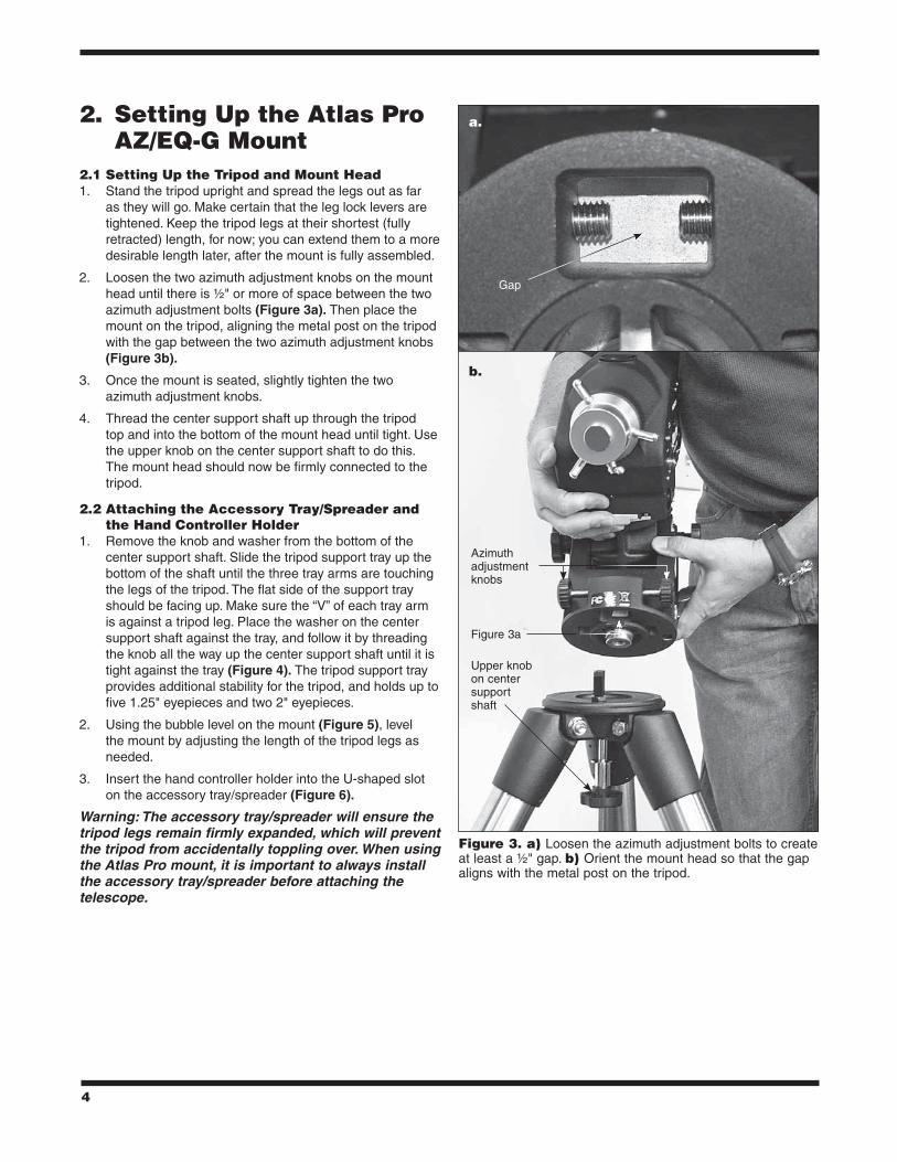
2. Loosen the two azimuth adjustment knobs on the mount head until there is ½" or more of space between the two azimuth adjustment bolts (Figure 3a). Then place the mount on the tripod, aligning the metal post on the tripod with the gap between the two azimuth adjustment knobs (Figure 3b).
3. Once the mount is seated, slightly tighten the two azimuth adjustment knobs.
4. Thread the center support shaft up through the tripod top and into the bottom of the mount head until tight. Use the upper knob on the center support shaft to do this. The mount head should now be firmly connected to the tripod.
2.2 Attaching the Accessory Tray/Spreader and the Hand Controller Holder
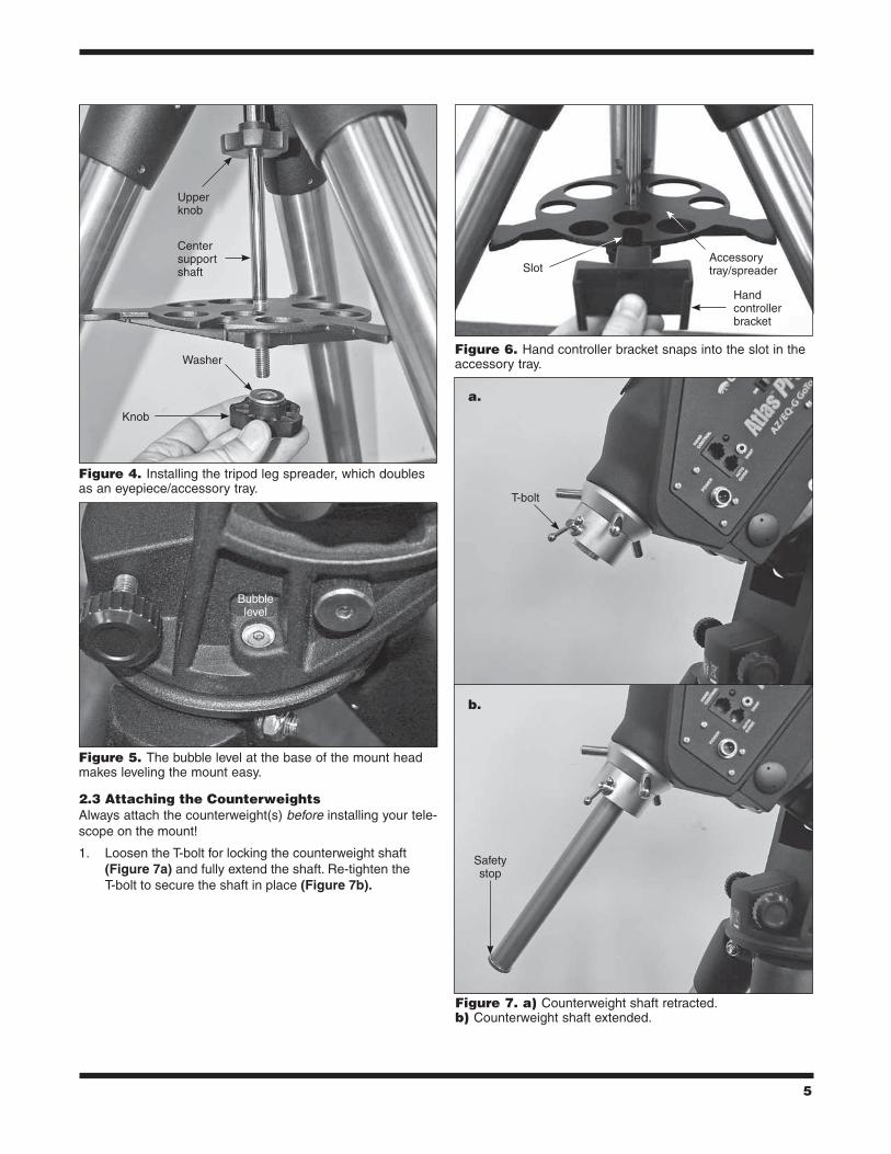
1. Remove the knob and washer from the bottom of the center support shaft. Slide the tripod support tray up the bottom of the shaft until the three tray arms are touching the legs of the tripod. The flat side of the support tray should be facing up. Make sure the “V” of each tray arm is against a tripod leg. Place the washer on the center support shaft against the tray, and follow it by threading the knob all the way up the center support shaft until it is tight against the tray (Figure 4). The tripod support tray provides additional stability for the tripod, and holds up to five 1.25" eyepieces and two 2" eyepieces.
2. Using the bubble level on the mount (Figure 5), level the mount by adjusting the length of the tripod legs as needed.
3. Insert the hand controller holder into the U-shaped slot on the accessory tray/spreader (Figure 6).
Warning:Theaccessorytray/spreaderwillensurethetripodlegsremainfirmlyexpanded,whichwillpreventthetripodfromaccidentallytopplingover.WhenusingtheAtlasPromount,itisimportanttoalwaysinstalltheaccessorytray/spreaderbeforeattachingthetelescope.
Figure 3. a) Loosen the azimuth adjustment bolts to create at least a ½" gap. b) Orient the mount head so that the gap aligns with the metal post on the tripod.
Azimuth adjustment knobs
Gap
Upper knob on center support shaft
Figure 3a
a.
b.
5
2.3 Attaching the CounterweightsAlways attach the counterweight(s) before installing your tele-scope on the mount!
1. Loosen the T-bolt for locking the counterweight shaft (Figure 7a) and fully extend the shaft. Re-tighten the T-bolt to secure the shaft in place (Figure 7b).
Figure 4. Installing the tripod leg spreader, which doubles as an eyepiece/accessory tray.
Figure 5. The bubble level at the base of the mount head makes leveling the mount easy.
Upper knob
Washer
Knob
Center support shaft
T-bolt
Safety stop
Bubble level
Figure 6. Hand controller bracket snaps into the slot in the accessory tray.
Figure 7. a) Counterweight shaft retracted. b) Counterweight shaft extended.
SlotAccessory tray/spreader
Hand controller bracket
a.
b.

6
2. Loosen the right ascension (R.A.) clutch with the handle (Figure 8a), and rotate the R.A. axis until the counterweight shaft is pointing toward the ground, as in Figure 7b.
3. Remove the knurled “toe saver” safety stop (Figure 7b) from the end of the counterweight shaft.
4. The Atlas Pro mount comes with a 150mm counterweight shaft extension (Figure 9), which can be installed at this point if necessary for balancing heavier payloads. Ensure that the extension is tightly secured before installing counterweights.
5. Loosen the counterweight’s lock knob and slide one or more counterweights onto the counterweight shaft as needed to balance your instrument. (See Section 2.5 for details on how to balance the telescope.) Retighten the lock knob to secure the counterweight on the shaft.
6. Replace the safety stop on the end of the counterweight shaft. The safety stop prevents the counterweights from falling on your foot if the lock knobs come loose.
2.4 installing a Telescope on the MountThe Atlas Pro mount is designed to hold a telescope payload of up to 44 lbs. For heavier telescopes, the mount may not provide sufficient stability for steady imaging.
1. Before installing a telescope, be sure that:
• The counterweight shaft is pointing toward the ground.
• The counterweights are installed on the counterweight shaft and have been moved to the bottom end of the shaft.
• The R.A. axis is secured by tightening the R.A. clutch.
2. Loosen the two clamp knobs on the primary dual-width saddle plate (Figure 10) until the width of one of the
Figure 8. a) Right ascension clutch. The handle can be placed in an adjacent hole if needed. b) Declination clutch.
Figure 10. The primary dual-width saddle accommodates narrow or wide dovetail plates.
Figure 9. The included 150mm counterweight shaft threads into the bottom of the main shaft.
R.A. clutch handle
Dec clutch “captain’s wheel”
75mm, wide
45mm, narrow
Clamp knobs
TIGHTEN
TIGHTEN
LOOSEN
LOO
SEN
a.
b.

7
dovetail grooves is slightly wider than the width of the dovetail bar on your telescope or telescope tube rings.
3. While holding the telescope, seat the dovetail bar of the telescope into the proper groove of the saddle. The lower groove is for a “narrow” (Vixen style), 45mm width dovetail bar and the upper groove is for a “wide” (Losmandy style), 75mm bar. Then tighten the two clamp knobs to secure the dovetail bar in the saddle.
Warning:Keepsupportingthetelescopeuntilyouaresureithasbeenfirmlyattachedtothesaddle!
2.5 Balancing the TelescopeTo minimize stress on the motor drive system and ensure smooth, accurate movement of a telescope on both axes of the mount, it is imperative that the optical tube be properly bal-
anced. We will first balance the telescope with respect to the right ascension (R.A.) axis, then the declination (Dec.) axis, in the equatorial mode.
1. Keeping one hand on the telescope optical tube, loosen the R.A. clutch (Figure 8a). Make sure the Dec. clutch “captain’s wheel” (Figure 8b) is tightened, for now. The telescope should now be able to rotate freely about the R.A. axis. Rotate it until the counterweight shaft is parallel to the ground (i.e., horizontal).
2. Now loosen the counterweight lock knob and slide the weight(s) along the shaft until it exactly counterbalances the telescope. That’s the point at which the shaft remains horizontal even when you let go with both hands. Once balance is achieved, retighten the counterweight lock knobs.
3. To balance the telescope on the Dec. axis, first tighten the R.A. clutch, with the counterweight shaft still in the horizontal position. Then with one hand on the telescope optical tube, loosen the Dec. clutch and check for any rotation. If there is some, adjust the telescope forward or back in the saddle or in its tube rings until it remains horizontal when you carefully let go of it.
The telescope is now balanced on both axes. When you loos-en the clutch on one or both axes and manually point the tele-scope, it should move without resistance and should not drift from where you point it.
3. using the Atlas Pro AZ ⁄EQ-G Mount
3.1 Manually rotating the MountThe mount can be moved manually by simply loosening the R.A. and Dec clutches and pointing the telescope to the desired location. Both the R.A. and Dec. clutches should be tightened when driving the mount with the internal motors.
3.2 using the Setting CirclesAs indicated in Figure 11a, the Atlas Pro features right ascen-sion and declination setting circles. Most users of a GoTo tele-scope will not have a need to use setting circles, but if you should, here’s how:
1. Before using the setting circles, they will need to be calibrated. Point the telescope toward a known object whose coordinates you have looked up (R.A.-Dec. coordinates or azimuth-altitude coordinates). Loosen the two locking thumbscrews on the setting circles and turn them so the coordinate values line up with the arrows on both the R.A. and Dec. setting circles, then retighten the locking screws.
2. Once the setting circles are calibrated, the mount can be moved either electronically or manually to specified coordinates by referring to the setting circle readings.
3. The R.A. setting circle features three different scales (Figure 11b): the upper scale is used to indicate the right ascension in Equatorial mode when mount is operating
Figure 11. a) R.A. and Dec. setting circles. b) The RA setting circle features three stacked numbers: top number is R.A. in EQ mode in Southern hemisphere; middle number is R.A. in EQ mode in Northern hemisphere; bottom number is azimuth angle in Alt-azimuth mode. The latitude scale and pointer are used to set the R.A. axis elevation to the latitude of your observing/imaging location.
Thumbscrew lock
Thumbscrew lock
Dec setting circle
RA setting circle
a.
b.
Latitude pointer
Latitude scale
R.A. setting circle
Three scales
8
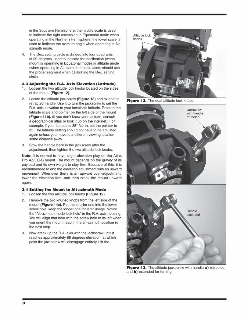
in the Southern Hemisphere; the middle scale is used to indicate the right ascension in Equatorial mode when operating in the Northern Hemisphere; the lower scale is used to indicate the azimuth angle when operating in Alt-azimuth mode.
4. The Dec. setting circle is divided into four quadrants of 90-degrees, used to indicate the declination (when mount is operating in Equatorial mode) or altitude angle (when operating in Alt-azimuth mode). Users should use the proper segment when calibrating the Dec. setting circle.
3.3 Adjusting the r.A. Axis Elevation (latitude)1. Loosen the two altitude lock knobs located on the sides
of the mount (Figure 12).
2. Locate the altitude jackscrew (Figure 13) and extend its retracted handle. Use it to turn the jackscrew to set the R.A. axis elevation to your location’s latitude. Refer to the latitude scale and pointer on the left side of the mount (Figure 11b). (If you don’t know your latitude, consult a geographical atlas or look it up on the internet.) For example, if your latitude is 35° North, set the pointer to 35. The latitude setting should not have to be adjusted again unless you move to a different viewing location some distance away.
3. Stow the handle back in the jackscrew after the adjustment, then tighten the two altitude lock knobs.
Note: It is normal to have slight elevation play on the Atlas Pro AZ/EQ-G mount. The mount depends on the gravity of its payload and its own weight to stay firm. Because of this, it is recommended to end the elevation adjustment with an upward movement. Whenever there is an upward over-adjustment, lower the elevation first, and then crank the mount upward again.
3.4 Setting the Mount to Alt-azimuth Mode1. Loosen the two altitude lock knobs (Figure 12).
2. Remove the two knurled knobs from the left side of the mount (Figure 14a). Put the shorter one into the lower screw hole; keep the longer one for later usage. Notice the “Alt-azimuth mode lock hole” in the R.A. axis housing. You will align that hole with the screw hole to its left when you orient the mount head in the alt-azimuth position in the next step.
3. Now crank up the R.A. axis with the jackscrew until it reaches approximately 88 degrees elevation, at which point the jackscrew will disengage entirely. Lift the
Figure 13. The altitude jackscrew with handle a) retracted, and b) extended for turning.
Figure 12. The dual altitude lock knobs.
Altitude lock knobs
Jackscrew with handle retracted
Handle extended
a.
b.
9
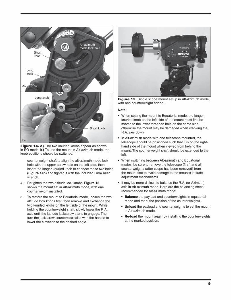
counterweight shaft to align the alt-azimuth mode lock hole with the upper screw hole on the left side, then insert the longer knurled knob to connect these two holes (Figure 14b) and tighten it with the included 5mm Allen wrench.
4. Retighten the two altitude lock knobs. Figure 15 shows the mount set in Alt-azimuth mode, with one counterweight installed.
5. To restore the mount to Equatorial mode, loosen the two altitude lock knobs first, then remove and exchange the two knurled knobs on the left side of the mount. While holding the counterweight shaft, slowly lower the R.A. axis until the latitude jackscrew starts to engage. Then turn the jackscrew counterclockwise with the handle to lower the elevation to the desired angle.
Note:
• When setting the mount to Equatorial mode, the longer knurled knob on the left side of the mount must first be moved to the lower threaded hole on the same side, otherwise the mount may be damaged when cranking the R.A. axis down.
• In Alt-azimuth mode with one telescope mounted, the telescope should be positioned such that it is on the right-hand side of the mount when viewed from behind the mount. The counterweight shaft should be extended to the left.
• When switching between Alt-azimuth and Equatorial modes, be sure to remove the telescope (first) and all counterweights (after scope has been removed) from the mount first to avoid damage to the mount’s latitude adjustment mechanisms.
• It may be more difficult to balance the R.A. (or Azimuth) axis in Alt-azimuth mode. Here are the balancing steps recommended for Alt-azimuth mode:
• Balance the payload and counterweights in equatorial mode and mark the position of the counterweights.
• Unload the payload and counterweights to set the mount in Alt-azimuth mode.
• Re-load the mount again by installing the counterweights at the marked position.
Figure 15. Single scope mount setup in Alt-Azimuth mode, with one counterweight added.
Figure 14. a) The two knurled knobs appear as shown in EQ mode. b) To use the mount in Alt-azimuth mode, the knob positions should be switched.
Short knob
Alt-azimuth mode lock hole
Long knob
Long knob
Short knob
a.
b.
10
3.5 Mounting a Second Telescope (Alt-azimuth mode only)
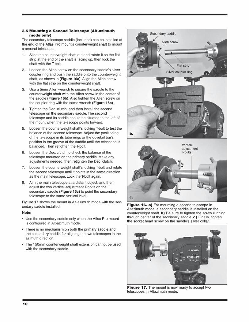
The secondary telescope saddle (included) can be installed at the end of the Atlas Pro mount’s counterweight shaft to mount a second telescope.
1. Slide the counterweight shaft out and rotate it so the flat strip at the end of the shaft is facing up, then lock the shaft with the T-bolt.
2. Loosen the Allen screw on the secondary saddle’s silver coupler ring and push the saddle onto the counterweight shaft, as shown in (Figure 16a). Align the Allen screw with the flat strip on the counterweight shaft.
3. Use a 5mm Allen wrench to secure the saddle to the counterweight shaft with the Allen screw in the center of the saddle (Figure 16b). Also tighten the Allen screw on the coupler ring with the same wrench (Figure 16c).
4. Tighten the Dec. clutch, and then install the second telescope on the secondary saddle. The second telescope and its saddle should be situated to the left of the mount when the telescope points forward.
5. Loosen the counterweight shaft’s locking T-bolt to test the balance of the second telescope. Adjust the positioning of the telescope in its tube rings or the dovetail bar’s position in the groove of the saddle until the telescope is balanced. Then retighten the T-bolt.
6. Loosen the Dec. clutch to check the balance of the telescope mounted on the primary saddle. Make any adjustments needed, then retighten the Dec. clutch.
7. Loosen the counterweight shaft’s locking T-bolt and rotate the second telescope until it points in the same direction as the main telescope. Lock the T-bolt again.
8. Aim the main telescope at a distant object, and then adjust the two vertical-adjustment T-bolts on the secondary saddle (Figure 16c) to point the secondary telescope to the same vertical level.
Figure 17 shows the mount in Alt-azimuth mode with the sec-ondary saddle installed.
Note:
• Use the secondary saddle only when the Atlas Pro mount is configured in Alt-azimuth mode.
• There is no mechanism on both the primary saddle and the secondary saddle for aligning the two telescopes in the azimuth direction.
• The 150mm counterweight shaft extension cannot be used with the secondary saddle.
Figure 16. a) For mounting a second telescope in Altazimuth mode, a secondary saddle is installed on the counterweight shaft. b) Be sure to tighten the screw running through center of the secondary saddle. c) Finally, tighten the socket head screw on the saddle’s silver collar.
Secondary saddle
Silver coupler ring
Flat strip
Allen screw
Vertical adjustment T-bolts
Figure 17. The mount is now ready to accept two telescopes in Altazimuth mode.
a.
b.
c.

11
4. Polar Alignment4.1 What is it?When you look at the night sky, you no doubt have noticed that the stars appear to move slowly from east to west over time. That motion is actually caused by the Earth’s rotation (from west to east). An equatorial mount is designed to compensate for that motion, allowing you to easily “track” the movement of astronomical objects, thereby keeping them from drifting out of your telescope’s field of view while you’re observing or imaging.
This “tracking” is accomplished by slowly rotating the tele-scope on its right ascension (R.A.) axis (Figure 18), using the built in motor drive. But first the R.A. axis of the mount must be aligned with the Earth’s rotational (polar) axis—a process called polar alignment.
For Northern Hemisphere operation, approximate polar align-ment is achieved by pointing the mount’s right ascension axis at the North Star, or Polaris. It lies within 1° of the north celes-tial pole (NCP), which is an extension of the Earth’s rotational axis out into space. Stars in the Northern Hemisphere appear to revolve around the NCP.
To find Polaris in the sky, look north and locate the pattern of the Big Dipper (Figure 19). The two stars at the end of the “bowl” of the Big Dipper point in the general direction of Polaris.
Observers in the Southern Hemisphere aren’t so fortunate to have a bright star so near the south celestial pole (SCP). The star Sigma Octantis lies about 1° from the SCP, but it is barely visible with the naked eye (magnitude 5.5).
4.2 The Polar Axis Finder ScopeThe Atlas Pro mount comes with a polar axis finder scope (Figure 20) housed inside the right ascension axis of the mount. When properly aligned and used, it makes accurate polar alignment quick and easy to do. The polar scope includ-ed with the Atlas Pro mount can be used for polar alignment in the Northern or Southern Hemispheres. That is, the polar scope’s reticle graphic has reference stars that are useful for aligning in either hemisphere. Remove the cap from the eye-piece of the polar scope to view through it.Figure 19. Polaris is easy to find in the northern sky by
extending an imaginary line from the two “pointer stars” of the Big Dipper. Polaris lies within 1 degree of the north celestial pole (NCP).
Figure 18. The R.A. and Dec. axes of the Atlas Pro AZ/EQ-G mount.
Dec
linat
ion
axis
Right ascension
axis
Polar axis scope
Big Dipper (in Ursa Major)
Little Dipper (in Ursa Minor)
Cassiopeia
N.C.P.
Pointer
Stars
Polaris
Figure 20. The polar axis finder scope, which comes preinstalled in the mount.
Eyepiece focus ring
Alignment setscrew (3)
Focus lock ring
Objective lens

12
4.3 Aligning the Polar Axis Scope to the r.A. AxisBefore using the polar scope for polar alignment, the polar scope itself must be aligned to the mount’s R.A. axis. The reticle of the polar axis finder scope has a tiny star map printed on it that makes precise polar alignment quick and easy (Figure 21). At the center of the reticle is a cross, which you’ll use in the pro-cedure below to align the polar scope to the R.A. axis.
1. Loosen the Dec. clutch wheel and rotate the optical tube about the declination axis until you have a clear view through the polar axis finder scope (Figure 22). Then retighten the Dec. clutch.
2. Look through the polar scope at a distant object (during the day) or at Polaris (at night) and center it on the cross in the middle of the reticle. You may need to adjust the latitude jackscrew and azimuth adjustment knobs of the mount and the tripod position to do this. Focus the polar scope by rotating its eyepiece.
3. Rotate the mount 180° about the R.A. axis. It may be convenient to remove the optical tube and counterweights before doing this. If the object remains centered on the center cross of the reticle after the rotation, then the polar scope is properly aligned to the R.A. axis and no adjustment is needed.
4. If the target deviated from the cross, then use a 1.5mm Allen wrench to adjust the three small Allen screws on the polar scope (Figure 23a) to move the target half the distance back to the cross (Figure 23b). Then you will re-center the object on the cross as in step 2 using the mount’s azimuth adjustment knobs and the latitude jackscrew.
5. Repeat steps 2 to 4 until the object stays centered on the cross of the reticle when rotating the mount on the R.A. axis.
Note:
• When adjusting the Allen screws, loosen one screw only ¼ of a turn, and then tighten the other two.
• Do not over tighten the Allen screws as it might damage the reticle plate in the polar scope.
• Do not loosen one screw completely or loosen more than one screw at a time, or the reticle plate in the polar scope will be disengaged and further adjustment is impossible.
• If the reticle plate does disengage, remove the polar scope’s eyepiece by turning the knurled ring counterclockwise and engage the reticle plate again.
4.4 Polar Alignment using the Polar Scope1. Set up the Atlas Pro mount. It is recommended to load
the mount with the counterweights and telescope (in that order!) and level the mount prior to polar alignment.
2. Move the tripod so the telescope tube and right ascension axis point roughly at Polaris (for Northern
Hemisphere) or toward the four dim stars (approx magnitude 5 or 6) of Octans (for Southern Hemisphere). You may need to adjust the altitude and azimuth adjustments to accomplish this.
3. Loosen the Dec. clutch wheel and rotate the optical tube about the declination axis until you have a clear view through the polar axis finder scope (Figure 22). Then retighten the Dec. clutch.
Figure 21. The reticle of the polar axis scope shows the positions of the Big Dipper and Cassiopeia relative to Polaris and the north celestial pole (NCP). For southern hemisphere users, four stars of the constellation Octans are depicted.
Figure 22. To view through the polar scope, rotate the Dec. axis of the mount until the opening in the Dec. shaft lines up with the opening in the mount housing.
Opening in declination shaft

13
4. Turn on the power to the mount to illuminate the polar scope. The reticle pattern (Figure 21) should now be visible in the polar scope. If the image appears blurred, rotate the polar scope’s knurled eyepiece to focus it.
Note: The red illumination of the polar scope reticle is adjust-able from 100% to 0% brightness. The default illumination is 100%, which may be too bright for readily seeing Polaris and surrounding stars. To reduce the brightness, access the menu “UTILITY \ Polar Scope LED” and press the ENTER key. Use the Left direction key to reduce the illumination to the desired level (probably 10% or less), then press the ENTER key to set it.
5. Now, sight Polaris in the polar axis finder scope. If it’s not in the field of view, move the mount left or right using the azimuth adjustment knobs, and adjust the altitude up or down using the jackscrew until Polaris is visible in the polar scope.
6. Note the constellation Cassiopeia and the Big Dipper in the reticle. They do not appear in scale, but they indicate the general positions of Cassiopeia and the Big Dipper relative to the NCP in the sky. Rotate the reticle so the star patterns depicted match their current orientation in the sky when viewed with the naked eye. To do this, release the R.A. clutch and rotate the main telescope around the R.A. axis until the reticle is oriented with sky. For larger optical tubes, you may need to remove the tube from the mount to prevent it from bumping into the mount during this procedure.
7. Now use the azimuth adjustment knobs and the latitude jackscrew on the mount to position Polaris inside the tiny circle on the finder’s reticle. You must first loosen – only very slightly! – the knob underneath the mount head on the center support shaft to use the azimuth adjustment knobs. Once Polaris is properly positioned within the reticle, you are precisely polar aligned. Retighten the knob under the mount and lightly tighten the altitude lock knobs on the sides of the mount.
Polar Alignment in Southern Hemisphere: In the field of view of the polar scope, locate the four dim stars that form the pattern labeled “Octans,” which lie near the South Celestial Pole. Loosen the R.A. clutch and rotate the R.A. axis to align the orientation of the “Octans” graphic to the same four stars in the actual sky. Then use the altitude jackscrew and the azi-muth adjustment knobs to move the four stars into the four small circles of the Octans graphic on the reticle. With that, the mount is now polar aligned for Southern Hemisphere viewing.
4.5 Another Way to Determine Position of Polaris on reticle
At the end of the initialization of the SynScan hand controller, after entering the proper local longitude, latitude, date, time, and daylight-saving time setting, the SynScan hand controller will display the message: “Polaris Position in P.Scope=HH:MM”. Imagine the larger circle in Figure 21 as a clock’s face with 12:00 at the top, with the current time pointing to the “HH:MM”. The orientation of the hour hand of the clock represents the orientation of Polaris in the polar scope. Place Polaris at the same orientation on the reticle’s large circle to finish the polar alignment.
Note: From this point on in your observing or imaging session, you should not make any further adjustments to the azimuth or the latitude of the mount, nor should you move the tripod. Doing so will disrupt the polar alignment. The telescope should be moved only about its right ascension and declination axes.
Figure 23. a) The polar axis scope has three alignment setscrews located near the eyepiece. b) After centering a distant target and rotating the mount 180 degrees in R.A., adjust the three alignment setscrews to move the target half the distance back to the center cross. Then use the mount’s latitude jackscrew and azimuth adjustment knobs to recenter the target.
Alignment setscrews (x3)
If Polaris (or daytime target) drifted to here
Place Polaris (or daytime target) here (half the distance)
a.
b.

14
5. Drive Panel interface5.1 Drive PanelThe drive panel of the Atlas Pro AZ/EQ-G is shown in Figure 24.
5.2 Panel interface Components:POWER: This is a threaded 12V DC power input jack that pro-vides a secure connection to the power source. The 12V DC “cigarette lighter” power cable provided with the mount has a matching threaded connector for the input jack.
HAND CONTROL: This RJ-45 8-pin jack is for connecting the coil cable of the SynScan hand controller.
AUTO GUIDE: A 6-pin RJ-12 jack is for connecting an autogu-ider. It is compatible with any autoguider with a ST-4 type interface.
SNAP: This 2.5mm stereo jack allows connection to a camera’s shutter control port. The SynScan hand controller can control a camera to take pictures automatically via this interface. The camera control cable included with the Atlas Pro mount is compatible with select Canon EOS series DSLR cameras. It has a right angle 2.5mm stereo plug on one end for connection to the drive panel and a straight 2.5mm plug on the other end for connection to the camera. Cables for other cameras can be sourced optionally or custom made.
ON/OFF Switch: Turns on and off the power to the mount and hand controller.
Power LED: The power LED serves as a power-on indicator and provides other status information:
1. Steady on: Power voltage is normal.
2. Slow flashing: Power voltage is low; continuing to operate the mount may damage the battery (if a 12V lead-acid battery is in use).
3. Fast flashing: Power voltage is extremely low; continuing to operate the mount may damage the battery and the motor controller in the mount.
4. Intermittent single flash: The PPEC training routine has been triggered, but the controller board in the mount has not received the worm index signal and the PE correction recording has not started yet.
5. Intermittent double flash: The PPEC training routine has been started and the controller board in the mount has received the worm index signal and started to record the PE correction. When the intermittent double flash stops, it means the PPEC training has finished.
6. Intermittent triple flash: Sidereal tracking with PEC is now enabled.
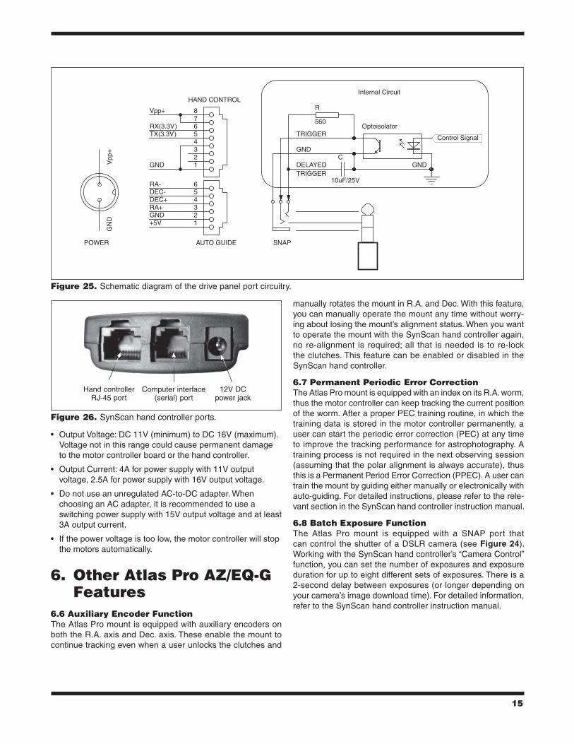
5.3 Pinout of the interfacesA schematic diagram of the drive panel port circuitry is shown in Figure 25.
Note:
• The SNAP port provides two trigger signals to the stereo plug. The signal to the head of the plug is issued slightly later than the signal to the ring of the plug.
• For a camera that needs only a shutter-release signal, either trigger signal will work. For a camera that requires a “Focus” signal ahead of the shutter-release signal, both signals will be utilized.
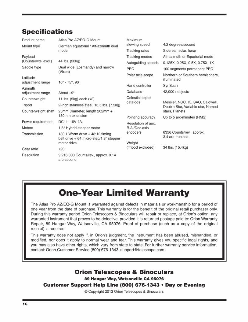
5.4 Attaching the SynScan GoTo Hand ControllerThe coil cable for the SynScan hand controller has RJ-45 connectors on each end. Plug one connector into the Hand Control port of the drive panel and the other connector into the RJ-45 port on the bottom of the SynScan controller (Figure 26). Push the connector into the port until it clicks into place.
The smaller modular port next to the RJ-45 port on the hand controller enables serial communication between the Atlas Pro mount and a computer running astronomy software such as Starry Night Pro. For that you will need the RS-232 computer interface cable that was included with the mount. If your com-puter does not have an RS-232 port, you will also need a USB-to-serial adapter. Check telescope.com for an available adapter.
The 12V DC power jack on the hand controller is used only for updating the firmware in the hand controller or for browsing the object database without connecting to the telescope mount. Do not connect the hand controller to a power source when using the mount for normal operation!
5.5 Power Supply RequirementsThe Atlas Pro AZ/EQ-G should be powered by a 12V DC or AC-to-DC power supply with a 3-amp or higher output cur-rent rating. (A 2A AC adapter of the type recommended for the Atlas EQ-G mount will not work for the Atlas Pro.)
Figure 24. The drive panel of the Atlas Pro AZ/EQ-G
Power LED
15
• Output Voltage: DC 11V (minimum) to DC 16V (maximum). Voltage not in this range could cause permanent damage to the motor controller board or the hand controller.
• Output Current: 4A for power supply with 11V output voltage, 2.5A for power supply with 16V output voltage.
• Do not use an unregulated AC-to-DC adapter. When choosing an AC adapter, it is recommended to use a switching power supply with 15V output voltage and at least 3A output current.
• If the power voltage is too low, the motor controller will stop the motors automatically.
6. Other Atlas Pro AZ/EQ-G Features
6.6 Auxiliary Encoder FunctionThe Atlas Pro mount is equipped with auxiliary encoders on both the R.A. axis and Dec. axis. These enable the mount to continue tracking even when a user unlocks the clutches and
manually rotates the mount in R.A. and Dec. With this feature, you can manually operate the mount any time without worry-ing about losing the mount’s alignment status. When you want to operate the mount with the SynScan hand controller again, no re-alignment is required; all that is needed is to re-lock the clutches. This feature can be enabled or disabled in the SynScan hand controller.
6.7 Permanent Periodic Error CorrectionThe Atlas Pro mount is equipped with an index on its R.A. worm, thus the motor controller can keep tracking the current position of the worm. After a proper PEC training routine, in which the training data is stored in the motor controller permanently, a user can start the periodic error correction (PEC) at any time to improve the tracking performance for astrophotography. A training process is not required in the next observing session (assuming that the polar alignment is always accurate), thus this is a Permanent Period Error Correction (PPEC). A user can train the mount by guiding either manually or electronically with auto-guiding. For detailed instructions, please refer to the rele-vant section in the SynScan hand controller instruction manual.
6.8 Batch Exposure FunctionThe Atlas Pro mount is equipped with a SNAP port that can control the shutter of a DSLR camera (see Figure 24). Working with the SynScan hand controller’s “Camera Control” function, you can set the number of exposures and exposure duration for up to eight different sets of exposures. There is a 2-second delay between exposures (or longer depending on your camera’s image download time). For detailed information, refer to the SynScan hand controller instruction manual.
Figure 25. Schematic diagram of the drive panel port circuitry.
234
1
5678
HAND CONTROL
GND
Vpp+
RX(3.3V)TX(3.3V)
234
1
56
AUTO GUIDE
GND
Vpp
+G
ND +5V
RA+
RA-
DEC+DEC-
R
560
C
10uF/25V
SNAP
Optoisolator
GND
POWER
Control Signal
Internal Circuit
GND
TRIGGER
DELAYEDTRIGGER
Figure 26. SynScan hand controller ports.
Hand controller RJ-45 port
Computer interface (serial) port
12V DC power jack
16
SpecificationsProduct name Atlas Pro AZ/EQ-G Mount
Mount type German equatorial / Alt-azimuth dual mode
Payload (Counterwts. excl.) 44 lbs. (20kg)
Saddle type Dual wide (Losmandy) and narrow (Vixen)
Latitude adjustment range 10° - 75°, 90°
Azimuth adjustment range About ±9°
Counterweight 11 lbs. (5kg) each (x2)
Tripod 2-inch stainless steel, 16.5 lbs. (7.5kg)
Counterweight shaft 25mm Diameter, length 202mm + 150mm extension
Power requirement DC11~16V 4A
Motors 1.8° Hybrid stepper motor
Transmission 180:1 Worm drive + 48:12 timing belt drive + 64 micro-step/1.8° stepper motor drive
Gear ratio 720
Resolution 9,216,000 Counts/rev., approx. 0.14 arc-second
Maximum slewing speed 4.2 degrees/second
Tracking rates Sidereal, solar, lunar
Tracking modes Alt-azimuth or Equatorial mode
Autoguiding speeds 0.125X, 0.25X, 0.5X, 0.75X, 1X
PEC 100 segments permanent PEC
Polar axis scope Northern or Southern hemisphere, illuminated
Hand controller SynScan
Database 42,000+ objects
Celestial object catalogs Messier, NGC, IC, SAO, Caldwell, Double Star, Variable star, Named stars, Planets
Pointing accuracy Up to 5 arc-minutes (RMS)
Resolution of aux. R.A./Dec.axis encoders 6356 Counts/rev., approx. 3.4 arc-minutes
Weight (Tripod excluded) 34 lbs. (15.4kg)
One-Year limited WarrantyThe Atlas Pro AZ/EQ-G Mount is warranted against defects in materials or workmanship for a period of one year from the date of purchase. This warranty is for the benefit of the original retail purchaser only. During this warranty period Orion Telescopes & Binoculars will repair or replace, at Orion’s option, any warranted instrument that proves to be defective, provided it is returned postage paid to: Orion Warranty Repair, 89 Hangar Way, Watsonville, CA 95076. Proof of purchase (such as a copy of the original receipt) is required.
This warranty does not apply if, in Orion’s judgment, the instrument has been abused, mishandled, or modified, nor does it apply to normal wear and tear. This warranty gives you specific legal rights, and you may also have other rights, which vary from state to state. For further warranty service information, contact: Orion Customer Service (800) 676-1343; [email protected].
Orion Telescopes & Binoculars89 Hangar Way, Watsonville CA 95076
Customer Support Help Line (800) 676-1343 • Day or Evening© Copyright 2013 Orion Telescopes & Binoculars