Embed Size (px)
Citation preview

MANUAL / BRUKSANVISNING / GUIDE D’INSTRUCTIONS / BEDIENUNGSANLEITUNG
English Manual for MPDM-module 23400, Rev R10, 180409
OriLink®
Monitoring System
Multi Point Dispense Module, 23400
(Covers MPDM with PCB version 203 02 62 C and D, some features may be missing in earlier versions)

2(24)
Table of Contents
1. INTRODUCTION 4
2. MECHANICAL INSTALLATION 4
3. ELECTRIC INSTALLATION 4
3.1. MAINS, 230VAC SIDE 4 3.2. CIRCUIT BOARD, DC SIDE 4
3.2.1. Miscellaneous connections ................................................................................................................ 5 3.2.2. Communication ................................................................................................................................. 5 3.2.3. Meters and solenoid valves ............................................................................................................... 5 3.2.4. Optional connector ............................................................................................................................ 6 3.2.5. Other hardware features ................................................................................................................... 6
4. CONFIGURATION 7
4.1. CHECK BEFORE CONFIGURATION 7 4.2. SET-UP LOCK JUMPER 7 4.3. ADDRESSING THE MPDM 8 4.4. SET-UP MODE 8 4.5. CHANGE ADDRESS [MPDM//ADDRESS] 8 4.6. RECOMMENDATION FOR SETTING ADDRESSES 8 4.7. CHANGE SPHERE [MPDM//SNR] 9
5. ADMINISTRATE INTERNAL USERS (ONLY WITH SPECIFIC SOFTWARE VERSIONS) 9
5.1. ADD A USER [MPDM//INTUSERDB/ADDUSER] 9 5.2. REMOVE A USER [MPDM//INTUSERDB/DELUSER] 9
6. CONFIGURE THE PORTS 10
6.1. CONNECT A DISPENSE POINT TO A PORT [MPDM//PORTX/REELNO] 10 6.2. GROUP [MPDM//PORTX/GROUP] 10 6.3. MASK [MPDM//PORTX/MASK] 11
6.3.1. Use PIN code ................................................................................................................................... 11 6.3.2. Use JOB no ..................................................................................................................................... 11 6.3.3. Use Volume ..................................................................................................................................... 11 6.3.4. Use Pulse compensation .................................................................................................................. 11 6.3.5. Use two REED switches .................................................................................................................. 11 6.3.6. Use external User Validation .......................................................................................................... 11 6.3.7. Use external JOB validation ........................................................................................................... 11 6.3.8. Use external Tank validation .......................................................................................................... 12 6.3.9. Use Input B as a trigger .................................................................................................................. 12 6.3.10. LED counts down ............................................................................................................................ 12 6.3.11. Dual/Quadra pulse count ................................................................................................................ 12 6.3.12. Cyclic Dispense mode ..................................................................................................................... 12
6.4. SET ”TIME-OUT” FUNCTION [MPDM//PORTX/TIMEOUT] 12 6.5. CALIBRATING [MPDM//PORTX/PPU] 13
6.5.1. Manual ............................................................................................................................................ 13 6.5.2. Semi automatic ................................................................................................................................ 13 6.5.3. Decimal PPU................................................................................................................................... 14
6.6. SET VOLUME INTERVALS [MPDM//PORTX/MINV] AND [MPDM//PORTX/MAXV] 14 6.7. VALIDATION OF JOB NUMBER 14
7. CONNECT A DISPENSE POINT TO INFORMATION MODULES 15
7.1. CONNECT A DISPENSE POINT TO A PRINTER/DATABASE MODULE [MPDM//PORTX/DB] 15 7.2. CONNECT A DISPENSE POINT TO A LED MODULE [MPDM//PORTX/LED] 15 7.3. SET NUMBER OF DECIMALS ON A LED MODULE [MPDM//PORTX/NODEC] 16 7.4. CONNECT A DISPENSE POINT TO A TANK [MPDM//PORTX/TANK] 16
8. MENU TREE. 17
9. FAST MENU CODES 18

3(24)
10. TECHNICAL SPECIFICATION 19
11. PM PCB MOUNTED IN A MPDM BOX 20
12. PRE-PROGRAMMED AMOUNTS WITH A MPDM 21
12.1. CONNECT A MPDM TO DISPENSE PRE-PROGRAMMED AMOUNTS 21 12.2. CONFIGURE A MPDM TO DISPENSE PRE-PROGRAMMED AMOUNTS 21 12.3. STATUS INFORMATION 21 12.4. START, STOP AND RESET FUNCTION. 21
13. USING THE MPDM AS A PLC (PROGRAMMABLE LOGIC CONTROLLER) 22
13.1. POSSIBLE INPUTS / OUTPUTS 22 13.2. SUPPORTED OPERATIONS 22 13.3. SAMPLE PLC CODED FUNCTIONS 22
13.3.1. Activate p4o with p4a for 60 s use r1 .............................................................................................. 22 13.3.2. Activate p4o with p4a for 10 s, if p4b is OFF Use r1 and deactivate p4o ...................................... 23 13.3.3. Flipp-flopp for p3o .......................................................................................................................... 23 13.3.4. Timed cascade coupling of Port1. ................................................................................................... 23 13.3.5. Start a pump p4o if the system is opened and activate p3o if it is closed ........................................ 23 13.3.6. Start control for a system with two pumps ...................................................................................... 23
14. CHIP TYPES. 24
14.1. DEMANDS ON A NON-PC SYSTEM. 24 14.2. DEMANDS ON A PC SYSTEM. 24 14.3. HOW TO SEE THE DIFFERENCE BETWEEN CHIP TYPES . 24 14.4. WHAT IS THE BENEFIT OF THE FLASH CHIP. 24
4(24)
1. Introduction
The MPDM, (Multi Point Dispense Module), is the engine in an OriLink® monitoring system. It measures the
dispensed volume and opens / closes the solenoid valve. A KP, (KeyPad), connected to a MPDM gives the smallest and
simplest OriLink® monitoring system. Each MPDM connected to an OriLink
® monitoring system four more dispense
points.
NOTE! The Orilink® installation manual should be available when installing and configuring a
MPDM.
2. Mechanical installation
The MPDM is delivered mounted in a metal box with power supply. It can also be delivered as a PCB with mounting
kit.
Complete MPDM in a box is mounted on a wall or other suitable place using the four-ø5 mm holes in the bottom
corners of the box.
If a PCB is used it is important that a power supply with enough performance is used.
3. Electric installation
When installing the MPDM (23400) there are different areas of connection.
Note! Before connecting the module or maintenance, make sure that the mains power is shut down.
3.1. Mains, 230VAC side
The MPDM should be connected to mains
230VAC/50Hz using phase, common and ground.
Alentec & Orion AB recommend that the connection is
done through a 2-pole lockable working switch.
The “knock-out” holes on the lower right hand (see
picture) should only be used for mains power supply to
separate it from the control (DC) side of the module.
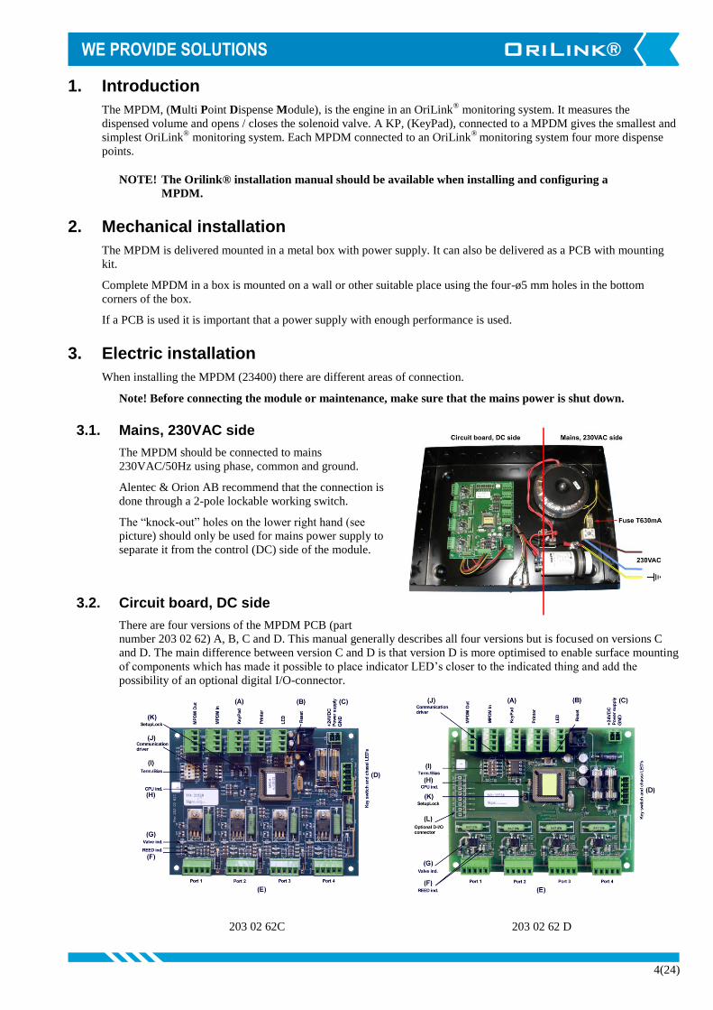
3.2. Circuit board, DC side
There are four versions of the MPDM PCB (part
number 203 02 62) A, B, C and D. This manual generally describes all four versions but is focused on versions C
and D. The main difference between version C and D is that version D is more optimised to enable surface mounting
of components which has made it possible to place indicator LED’s closer to the indicated thing and add the
possibility of an optional digital I/O-connector.
203 02 62C 203 02 62 D

5(24)
3.2.1. Miscellaneous connections
24 VDC is connected to the connector (C). In a MPDM (23400) this is already connected.
NOTE! If the connector (C) has been removed and should be reconnected, check polarity!
The poles are labelled on the circuit board. Red cable is +24VDC and Black is
GND.
The chassis-mounted key switch and indication diodes are connected
connector (D).
With the key switch you can set the status of the module to NORMAL-
(GREEN light), OFF- (NO light) or OVERRIDE- (RED light) mode.
In a MPDM (23400) this is already connected.
3.2.2. Communication
It has five connectors (A) for the OriLink® communication. Two of these connectors, MPDM IN and
MPDM OUT are not connected to +24V and are intended for a connection to other MPDM’s or other
modules that already have +24VDC. This is to prevent interconnecting of +24VDC from two power
supplies.
The other three connectors are used to connect external devices without a power source such as a Printer
Module (PM), a LED Module (LED) and/or a KeyPad (KP). These connectors can only supply power to a
single device. For more detailed information see the OriLink® Manual
NOTE! If the communication loop begin in one of these modules it must be connected to
either MPDM IN or MPDM OUT or +24V must not be connected.
NOTE! Communication cables should only be connected through “knock-out” holes to the
left side (“cirquit board side”) of the module to prevent mixing of mains 230VAC
and 24VDC cables.
3.2.3. Meters and solenoid valves
The four connectors (E) market +24 V, OC, A, B and GND are used for dispense points. Solenoid valves
and meters are connected to these.
24736 and similar 24738 and similar
A on the MPDM port is connects to A on the meter.
B on the MPDM port connects to B on the meter if it is equipped with two REED switches and both of
them should be used.
GND on the MPDM port connects to Com on the meter.
+24 V on the MPDM connects to o on the meter.
Sol on the MPDM connects to the unmarked hub on the meter.
The solenoid valve connects between o and the unmarked hub on the meter.
The meter 24728/24736 is equipped with a valve symbol to indicate open dispense point.

6(24)
TIP! If the Alentec & Orion AB stock cable, (part. Nr. 23 393), is used the colours
should match the following:
BROWN to +24V
YELLOW to Sol
WHITE to A
GREY to B A meter that has 2 pulse train outputs and cable 23412
(Optional)
GREEN to GND
This will make service and support much faster
NOTE! Meter and solenoid valve cables should only be connected through “knock-out”
holes to the left side (“cirquit board side”) of the module to prevent mixing of
mains 230VAC and 24VDC cables.
3.2.4. Optional connector
To simplify the use of the optional digital (5VDC) I/O connector a Phoenix MCV 1,5/8-G-3,81 (or equal)
can be soldered to the PCB. Then a Phoenix MC 1,5/8-ST-3,81 connector can be used for connecting
things.
To control more power than just 5VDC TTL a solid state TTL to power relay can be used. Our part
number 339 00 68 is a 5-pole 5VDC TLL to 10 - 36VDC 5A relay.
3.2.5. Other hardware features
The RESET-button (B) can be used to reset the module or reset the module address.
There are two diodes (F) for every port. These indicate the status of pulse inputs A and B
One diode on each port indicates if that dispense point is open or not, (G).
If the diode (H) is flashing the module is operational and working properly. A steady light or completely
off indicates a problem.
DIL-switch for termination and BIAS are located at (I).
(J) shows the position of the replaceable communication driver.
If the SetupLock jumper at position (K) is removed, the PPU value (calibration) cannot be changed.
On version D there is a possibility to add an optional 6-channel digital I/O connector with +5VDC and
GND, this is marked (L).
7(24)
4. Configuration
An Orilink® configuration sheet should always be filled or altered during the configuration.
NOTE! To obtain technical support a copy of the configuration sheet for the complete installation must be
sent to Alentec & Orion AB at
Alentec & Orion AB TECHNICAL SUPPORT BOX 108 S-132 23 Saltsjö-Boo SWEDEN or [email protected].
4.1. Check before configuration
Check that the MPDM is working and communicating with the system according to the
Orilink® Manual chapter Testing modules.
NOTE! Do not forget to check and adjust the termination and BIAS according to Orilink®
Manual.
4.2. Set-Up Lock jumper
On later MPDM boards there is a Jumper called SetupLock (revision C and D) if this jumper is removed or moved
to only one of the pins some configurations are disabled. Which configurations that are disabled may vary
depending on the chip software version. If you change a configuration from a keypad when the jumper is moved the
change will not be stored. If you configure from a PC the locked parameters is greyed and the flag L is shown in the
“Update PNP array” table.
8(24)
Reel:SETUP ‡
EXIT STOP CE ENT
PASS:_ ‡
Enter Password
Addr:1???_ ‡
Address[CODE]
MPDM: ‡
MPDM MainMenu
MPDM: ‡
MPDM MainMenu
Address:1XXX ‡
Ange Adress 1???
Address:1XXX ‡
Set Address 1???
4.3. Addressing the MPDM
A new module has a default address when delivered such as MPDM 1000, PM 2000, KP 3000, LED 4000 and so
on. To set an address for a new MPDM or a MPDM with unknown address press and hold it’s RESET button for 5
seconds to set a temporary address. Immediately enter set-up mode from a KP and type 0 and then ENTER to get to
the Main menu of the MPDM, see below.
NOTE! Only one new module can be installed at a time. If you press the RESET-button on several
terminals simultaneously or in a sequence, only the most recently pressed will be active.
TIP! Follow preferably ”Recommendation for setting new addresses” when setting addresses.
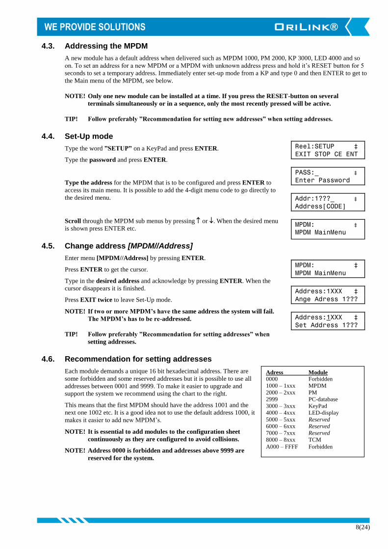
4.4. Set-Up mode
Type the word ”SETUP” on a KeyPad and press ENTER.
Type the password and press ENTER.
Type the address for the MPDM that is to be configured and press ENTER to
access its main menu. It is possible to add the 4-digit menu code to go directly to
the desired menu.
Scroll through the MPDM sub menus by pressing or . When the desired menu
is shown press ENTER etc.
4.5. Change address [MPDM//Address]
Enter menu [MPDM//Address] by pressing ENTER.
Press ENTER to get the cursor.
Type in the desired address and acknowledge by pressing ENTER. When the
cursor disappears it is finished.
Press EXIT twice to leave Set-Up mode.
NOTE! If two or more MPDM’s have the same address the system will fail.
The MPDM’s has to be re-addressed.
TIP! Follow preferably ”Recommendation for setting addresses” when
setting addresses.
4.6. Recommendation for setting addresses
Each module demands a unique 16 bit hexadecimal address. There are
some forbidden and some reserved addresses but it is possible to use all
addresses between 0001 and 9999. To make it easier to upgrade and
support the system we recommend using the chart to the right.
This means that the first MPDM should have the address 1001 and the
next one 1002 etc. It is a good idea not to use the default address 1000, it
makes it easier to add new MPDM’s.
NOTE! It is essential to add modules to the configuration sheet
continuously as they are configured to avoid collisions.
NOTE! Address 0000 is forbidden and addresses above 9999 are
reserved for the system.
Adress Module
0000 Forbidden
1000 – 1xxx MPDM
2000 – 2xxx PM
2999 PC-database
3000 – 3xxx KeyPad
4000 – 4xxx LED-display
5000 – 5xxx Reserved
6000 – 6xxx Reserved
7000 – 7xxx Reserved
8000 – 8xxx TCM
A000 – FFFF Forbidden
9(24)
MPDM: ‡
MPDM MainMenu
Address:1XXX ‡
Set Address 1???
Snr:XXX ‡
Set Sphere 0-255
Snr:XXX ‡
Set Sphere 0-255
MPDM: ‡
MPDM MainMenu
IntUserDB: ‡
MPDM MainMenu
DelUser: ‡
Delete User
AddUser: ‡
Add User
PIN:_ ‡
PIN ????
PIN:_ ‡
PIN ????
MPDM: ‡
MPDM MainMenu
IntUserDB: ‡
MPDM MainMenu
DelUser: ‡
Delete User
PIN:XXXX ‡
PIN ????
XXXX ‡
PIN ????
PIN: ‡
PIN ????
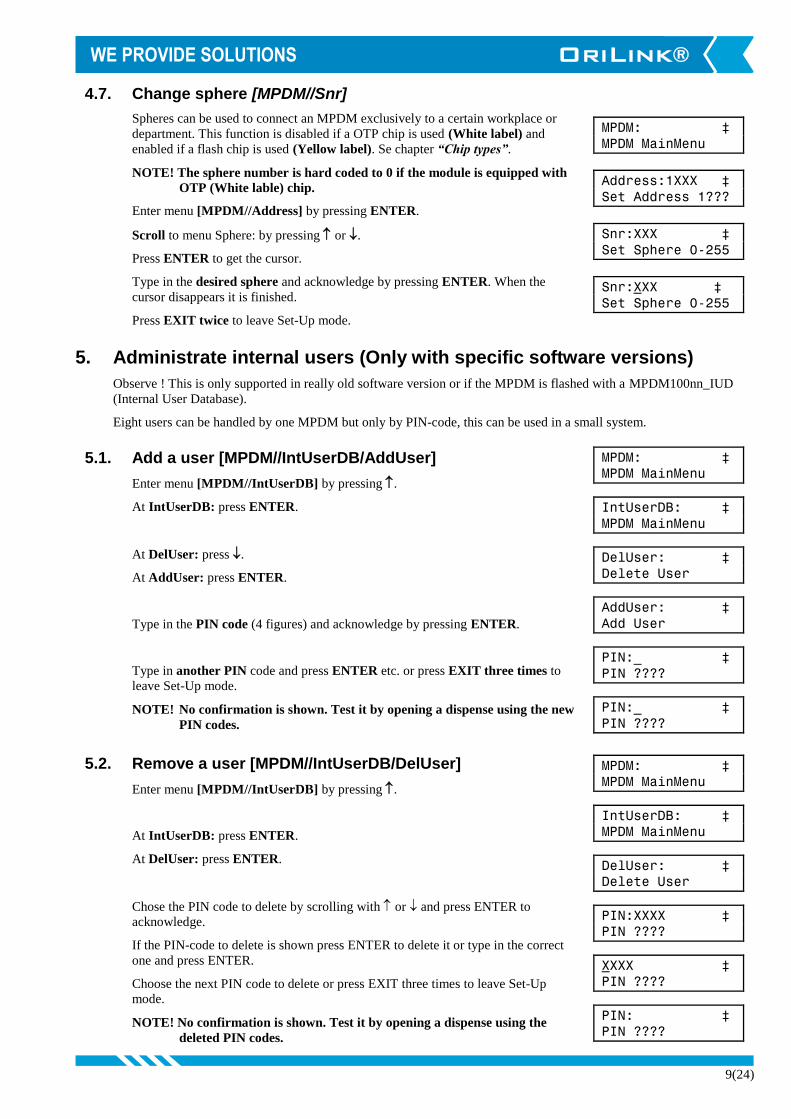
4.7. Change sphere [MPDM//Snr]
Spheres can be used to connect an MPDM exclusively to a certain workplace or
department. This function is disabled if a OTP chip is used (White label) and
enabled if a flash chip is used (Yellow label). Se chapter “Chip types”.
NOTE! The sphere number is hard coded to 0 if the module is equipped with
OTP (White lable) chip.
Enter menu [MPDM//Address] by pressing ENTER.
Scroll to menu Sphere: by pressing or .
Press ENTER to get the cursor.
Type in the desired sphere and acknowledge by pressing ENTER. When the
cursor disappears it is finished.
Press EXIT twice to leave Set-Up mode.
5. Administrate internal users (Only with specific software versions)
Observe ! This is only supported in really old software version or if the MPDM is flashed with a MPDM100nn_IUD
(Internal User Database).
Eight users can be handled by one MPDM but only by PIN-code, this can be used in a small system.
5.1. Add a user [MPDM//IntUserDB/AddUser]
Enter menu [MPDM//IntUserDB] by pressing .
At IntUserDB: press ENTER.
At DelUser: press .
At AddUser: press ENTER.
Type in the PIN code (4 figures) and acknowledge by pressing ENTER.
Type in another PIN code and press ENTER etc. or press EXIT three times to
leave Set-Up mode.
NOTE! No confirmation is shown. Test it by opening a dispense using the new
PIN codes.
5.2. Remove a user [MPDM//IntUserDB/DelUser]
Enter menu [MPDM//IntUserDB] by pressing .
At IntUserDB: press ENTER.
At DelUser: press ENTER.
Chose the PIN code to delete by scrolling with or and press ENTER to
acknowledge.
If the PIN-code to delete is shown press ENTER to delete it or type in the correct
one and press ENTER.
Choose the next PIN code to delete or press EXIT three times to leave Set-Up
mode.
NOTE! No confirmation is shown. Test it by opening a dispense using the
deleted PIN codes.

10(24)
MPDM: ‡
MPDM MainMenu
PortX: ‡
MPDM MainMenu
Reel:X ‡
Set ReelNo ???
Reel:X ‡
Set ReelNo ???
MPDM: ‡
MPDM Huvudmeny
PortX: ‡
MPDM Huvudmeny
Reel:X ‡
Set ReelNr ???
Group:XXX ‡
Set Group 0-255
Group:XXX ‡
Set Group 0-255
6. Configure the ports
A MPDM has four ports that are used to control four fully separate dispense points (Reels).
6.1. Connect a dispense point to a port [MPDM//PortX/ReelNo]
Enter menu [MPDM//PortX] by scrolling with or .
At PortX: press ENTER.
Press ENTER to get the cursor.
Check the number of the reel that is connected to portX, type that number in and
press ENTER to acknowledge. When the cursor disappears it is finished.
Press EXIT twice to leave Set-Up mode.
6.2. Group [MPDM//PortX/Group]
A user can be a member of eight different groups named A-H. It is possible to make
advanced and complex user rights for dispense points.
EXAMPLE: ”Bob” is a member of groups AB, user ”Stan” is a member of groups BC
and the dispense points is divided into three bays A, B and C. In this case both users can
open dispense points in bay B but only “Bob” can open dispense points in bay A and only
“Stan” can open dispense points in bay C.
Each group is represented by a value shown in the chart to the right. The group value is
calculated by adding the values for each desired group. Group A and E give a group value
of (1+16) which are 17.
Enter menu [MPDM//PortX/] by scrolling with or .
At PortX: press ENTER.
Scroll to Group: using or .
Press ENTER to get the cursor.
Type the group value and press ENTER to acknowledge. When the cursor
disappears it is finished.
Press EXIT twice to leave Set-Up mode.
NOTE: Which group a user is a member of is set when administrating users.
Group Value
A 1
B 2
C 4
D 8
E 16
F 32
G 64
H 128

11(24)
MPDM: ‡
MPDM MainMenu
PortX: ‡
MPDM MainMenu
Reel:X ‡
Set ReelNo ???
Mask:XXX ‡
Set Mask 0-3567
Mask:XXX ‡
Set Mask 0-3567
Mask:XXX ‡
Set Mask 0-3567
6.3. Mask [MPDM//PortX/Mask]
How a dispense point should work is controlled by a mask. This
is done by adding the values for the desired functions, in the chart
to the right.
EXAMPLE: At a dispense point you want to use JOB number
but you do not want to type in a desired volume or a PIN code.
The meter has two reed switches and you want to use them. In
this case you should add the values 2 and 16. 2+16=18. The mask
should be set to 18.
Enter menu [MPDM//PortX] by scrolling with or .
At PortX: press ENTER.
Scroll to Mask: using or .
Press ENTER to get the cursor.
Type the mask value and press ENTER to acknowledge. When the cursor
disappears it is finished.
Press EXIT twice to leave Set-Up mode.
6.3.1. Use PIN code
Sets if the dispense point should ask for a PIN code input or not.
6.3.2. Use JOB no
Sets if the dispense point should ask for a Workorder/JOB code input or
not.
6.3.3. Use Volume
Sets if the dispense point should ask for a volume input or not. If set the
dispense point will ask for a volume to dispense. If not set the dispense point will open for the volume
defined in MaxVol.
6.3.4. Use Pulse compensation
Sets if the dispense point should auto adjust for after run. If it is set the dispense point will adjust the valve
shut-of to compensate for flow and temperature changes.
6.3.5. Use two REED switches
Enables/Disables the use of a meter with two REED switches (Two pulse train output). If a meter with two
pulse trains (Alentec & Orion AB part no. 24738) is used and “Use two REED switches is enabled the flow
direction will be detected.
This cannot be used if “Use Input B as a trigger” is set.
6.3.6. Use external User Validation
If this is set the dispense point will validate the PIN code to the source specified in DbAddress. If it is not
set the dispense point will validate the PIN code to the internal PIN code database of the MPDM.
6.3.7. Use external JOB validation
If this is set the dispense point will validate the Work order/Job number to the source specified in
DBAdress. If it is not set the dispense point will only register the Work order/Job number but not validate
it.
Name Value
Use PIN-code 1
Use JOB-no 2
Use Volume 4
Use Pulse compensation 8
Use two REED switches 16
Use Ext User Validation 32
Use Ext JOB Validation 64
Use Ext Tank Validation 128
Use Input B as a trigger 256
LED counts down 512
Dual/Quadra pulse count 1024
Cyclic Dispense mode 2048
12(24)
MPDM: ‡
MPDM MainMenu
PortX: ‡
MPDM MainMenu
Reel:X ‡
Set ReelNo ???
Timer:X ‡
1-255 Min 0=Off
Timer:X ‡
1-255 Min 0=Off
Timer:X ‡
1-255 Min 0=Off
6.3.8. Use external Tank validation
If this is set the dispense point will validate the Requested volume to the specified Tank number at the
source specified in DBAdress. If the “Current Stock” minus the “Requested Volume” is above the specified
“Stop Volume” the dispense point will open.
6.3.9. Use Input B as a trigger
If this parameter is set it enables the use of an external signal connected to the Input B pin of the port
connector.
The function is active low and can be done with a push button connected between Input B and GND of the
port connector.
When Input B goes low the dispense point will open for the volume specified by the MaxVol parameter.
This cannot be used if “Use two REED switches” is set.
6.3.10. LED counts down
Sets if the LED specified by the parameter LEDAdress should count the dispensed volume forwards or
backwards, 0 -> Requested volume or Requested volume ->0.
6.3.11. Dual/Quadra pulse count
This sets if the pulse input of the dispense poin should count only rising edge or rising and falling edge of
the pulse train. If a single pulse train meter is used the PPU will be doubled and if a two pulse train meter is
used the PPU will increased 4 times.
This can be used to increase accuracy for grease dispensing and large meters with low PPU.
6.3.12. Cyclic Dispense mode
If this is set the dispense point dispenses the volume specified by the MaxVol parameter with a time
interval specified by the Time-Out parameter in minutes. Then the normal Time-Out for the dispense point
is hard coded to 30 seconds. If there is an error it is possible to get an error signal output on the optional I/O
connector on the MPDM board rev 2030262D.
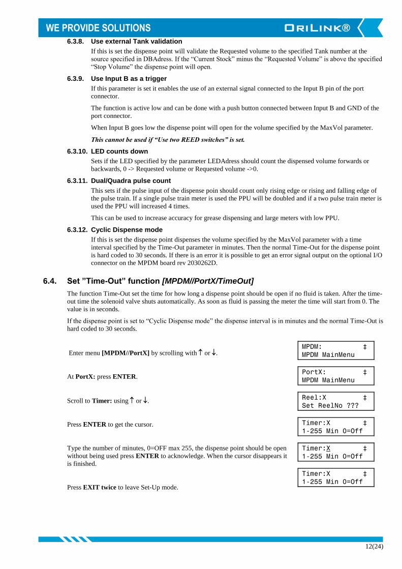
6.4. Set ”Time-Out” function [MPDM//PortX/TimeOut]
The function Time-Out set the time for how long a dispense point should be open if no fluid is taken. After the time-
out time the solenoid valve shuts automatically. As soon as fluid is passing the meter the time will start from 0. The
value is in seconds.
If the dispense point is set to “Cyclic Dispense mode” the dispense interval is in minutes and the normal Time-Out is
hard coded to 30 seconds.
Enter menu [MPDM//PortX] by scrolling with or .
At PortX: press ENTER.
Scroll to Timer: using or .
Press ENTER to get the cursor.
Type the number of minutes, 0=OFF max 255, the dispense point should be open
without being used press ENTER to acknowledge. When the cursor disappears it
is finished.
Press EXIT twice to leave Set-Up mode.
13(24)
MPDM: ‡
MPDM MainMenu
PortX: ‡
MPDM MainMenu
Reel:X ‡
Set ReelNo ???
PPU:XXX ‡
Set PPU 1-5000
PPU:XXX ‡
Set PPU 1-5000
PPU:XXX ‡
Set PPU 1-5000
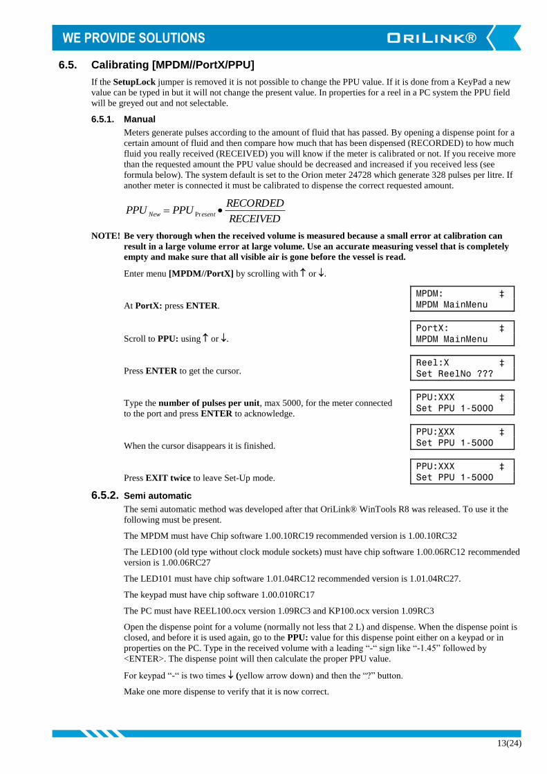
6.5. Calibrating [MPDM//PortX/PPU]
If the SetupLock jumper is removed it is not possible to change the PPU value. If it is done from a KeyPad a new
value can be typed in but it will not change the present value. In properties for a reel in a PC system the PPU field
will be greyed out and not selectable.
6.5.1. Manual
Meters generate pulses according to the amount of fluid that has passed. By opening a dispense point for a
certain amount of fluid and then compare how much that has been dispensed (RECORDED) to how much
fluid you really received (RECEIVED) you will know if the meter is calibrated or not. If you receive more
than the requested amount the PPU value should be decreased and increased if you received less (see
formula below). The system default is set to the Orion meter 24728 which generate 328 pulses per litre. If
another meter is connected it must be calibrated to dispense the correct requested amount.
RECEIVED
RECORDEDPPUPPU esentNew Pr
NOTE! Be very thorough when the received volume is measured because a small error at calibration can
result in a large volume error at large volume. Use an accurate measuring vessel that is completely
empty and make sure that all visible air is gone before the vessel is read.
Enter menu [MPDM//PortX] by scrolling with or .
At PortX: press ENTER.
Scroll to PPU: using or .
Press ENTER to get the cursor.
Type the number of pulses per unit, max 5000, for the meter connected
to the port and press ENTER to acknowledge.
When the cursor disappears it is finished.
Press EXIT twice to leave Set-Up mode.
6.5.2. Semi automatic
The semi automatic method was developed after that OriLink® WinTools R8 was released. To use it the
following must be present.
The MPDM must have Chip software 1.00.10RC19 recommended version is 1.00.10RC32
The LED100 (old type without clock module sockets) must have chip software 1.00.06RC12 recommended
version is 1.00.06RC27
The LED101 must have chip software 1.01.04RC12 recommended version is 1.01.04RC27.
The keypad must have chip software 1.00.010RC17
The PC must have REEL100.ocx version 1.09RC3 and KP100.ocx version 1.09RC3
Open the dispense point for a volume (normally not less that 2 L) and dispense. When the dispense point is
closed, and before it is used again, go to the PPU: value for this dispense point either on a keypad or in
properties on the PC. Type in the received volume with a leading “-“ sign like “-1.45” followed by
<ENTER>. The dispense point will then calculate the proper PPU value.
For keypad “-“ is two times (yellow arrow down) and then the “?” button.
Make one more dispense to verify that it is now correct.

14(24)
MaxV:X.XX ‡
Max Vol ????.??
MaxV:X.XX ‡
Max Vol ????.??
MaxV:X.XX ‡
Max Vol ????.??
MPDM: ‡
MPDM MainMenu
PortX: ‡
MPDM MainMenu
Reel:X ‡
Set ReelNo ???
MinV:X.XX ‡
Min Vol ??.??
MinV:X.XX ‡
Min Vol ??.??
MinV:X.XX ‡
Min Vol ??.??
6.5.3. Decimal PPU
If a MPDM is flashed with a chip software named MPDM……..(PPUFloat).bin it will support the use of
decimal (float number) PPU.
Decimal PPU: looks like this “326.54” compared to integer PPU: like 326.
To be able to set decimal PPU the keypad must have chip software 1.00.10RC17 and the PC must have the
REEL100.ocx version 1.09RC3.
6.6. Set volume intervals [MPDM//PortX/MinV] and [MPDM//PortX/MaxV]
Enter menu [MPDM//PortX] by scrolling with or .
At PortX: press ENTER.
Scroll to MinV: using or . (Or scroll directly to MaxV:)
Press ENTER to get the cursor.
Type the smallest volume, min 0,5, to be dispensed from this dispense point and
press ENTER. When the cursor disappears it is finished.
Press to MaxV: (Or press EXIT two times to leave Set-Up mode.)
Press ENTER to get the cursor.
Type the largest volume, min 0,5 max 9999,99, to be from this dispense point and
press ENTER to acknowledge. When the cursor disappears it is finished.
Press EXIT twice to leave Set-Up mode.
6.7. Validation of JOB number
MPDM dispense points create dispense records for entered job numbers entered when a dispense is done.
If there is a Printer module in the system or if WinDB service is loaded in a PC system, an entered job number can
be validated against a JOB number database, Se also 6.3. Mask.
15(24)
MPDM: ‡
MPDM MainMenu
PortX: ‡
MPDM MainMenu
Reel:X ‡
Set ReelNo ???
DB:2??? ‡
DB Address 2???
DB:2??? ‡
DB Address 2???
DB:2??? ‡
DB Address 2???
MPDM: ‡
MPDM MainMenu
PortX: ‡
MPDM MainMenu
Reel:X ‡
Set ReelNo ???
LED:4??? ‡
LED Address 4???
LED:4??? ‡
LED Address 4???
LED:4??? ‡
LED Address 4???
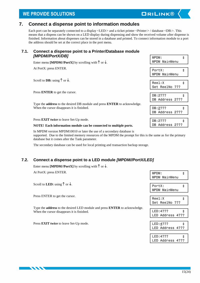
7. Connect a dispense point to information modules
Each port can be separately connected to a display <LED:> and a ticket printer <Printer:> / database <DB:>. This
means that a dispens can be shown on a LED display during dispensing and show the received volume after dispense is
finished. Information about dispenses can be stored in a database and printed. To connect information module to a port
the address should be set at the correct place in the port menu.
7.1. Connect a dispense point to a Printer/Database module [MPDM//PortX/DB]
Enter menu [MPDM//PortX] by scrolling with or .
At PortX: press ENTER.
Scroll to DB: using or .
Press ENTER to get the cursor.
Type the address to the desired DB module and press ENTER to acknowledge.
When the cursor disappears it is finished.
Press EXIT twice to leave Set-Up mode.
NOTE! Each information module can be connected to multiple ports.
In MPDM version MPDM10010 or later the use of a secondary database is
supported. Due to the limited memory resources of the MPDM the prompt for this is the same as for the primary
database but it comes after the Tank parameter.
The secondary database can be used for local printing and transaction backup storage.
7.2. Connect a dispense point to a LED module [MPDM//PortX/LED]
Enter menu [MPDM//PortX] by scrolling with or .
At PortX: press ENTER.
Scroll to LED: using or .
Press ENTER to get the cursor.
Type the address to the desired LED module and press ENTER to acknowledge.
When the cursor disappears it is finished.
Press EXIT twice to leave Set-Up mode.

16(24)
MPDM: ‡
MPDM MainMenu
PortX: ‡
MPDM MainMenu
Reel:X ‡
Set ReelNo ???
NoDec:2 ‡
LED Address 4???
NoDec:2 ‡
LED Address 4???
NoDec:2 ‡
LED Address 4???
7.3. Set number of decimals on a LED module [MPDM//PortX/NoDec]
Enter menu [MPDM//PortX] by scrolling with or .
At PortX: press ENTER.
Scroll to LED: using or .
Press ENTER to get the cursor.
Type how many decimals that should be shown for the port and press ENTER to
acknowledge.
When the cursor disappears it is finished.
Press EXIT twice to exit Mode-mode
Note! The number of decimals will automatically decrease to fit in the display if needed. Setting
number of decimals to 255 will result in 2 decimals.
7.4. Connect a dispense point to a tank [MPDM//PortX/Tank]
If there is a printer module in the system, a dispense point can be connected to one of max 8 tanks per PM. In this
case the system will be able to check if there is enough oil in the tank and subtract the oil dispensed from it.
Enter menu [MPDM//PortX], scroll with or .
Press ENTER.
Scroll to Tank: using or .
Press ENTER to get the cursor
Type which tank is connected to the port and press ENTER to acknowledge.
When the cursor disappears it is finished.
Press EXIT twice to exit Mode-mode
MPDM: ‡
MPDM MainMenu
PortX: ‡
MPDM MainMenu
Reel:X ‡
Set ReelNo ???
Tank:X ‡
Set TankNo
Tank:X ‡
Set TankNo
Tank:X ‡
Set TankNo

17(24)
8. Menu tree.

18(24)
9. Fast Menu codes
With a PC and the OriLink® WinTools software and a SIO, you can customize the quick menu that appear when
you press ”?”. To do this, assign a name to the menu, a module address and then a code. Password is optional. This
code can also be used together with the address after you have typed SETUP followed by the password.
For an MPDM-module it will look like this,
New user 10000062 YYYYY where YYYYY=password
Part Function Address Code Comment
Main menu Change address 0800
Change Sphere 0801
Reboot 0802 Not from keypad only from
command line
OLSET address 0802 22 R
Ports Change Dispense point Nr. 0X00 Where X is the port number
Change Group 0X01 Where X is the port number
Change Mask 0X02 Where X is the port number
Change Time-Out 0X03 Where X is the port number
Change PPU 0X04 Where X is the port number
Change Min Volume 0X05 Where X is the port number
Change Max Volume 0X06 Where X is the port number
Change DB address 0X07 Where X is the port number
Change LED address 0X08 Where X is the port number
Change Tank number 0X09 Where X is the port number
Change Number of decimals 0X10 Where X is the port number
Set Secondary DB address 0X11 Where X is the port number
Directly to dispense input 0X20 Where X is the port number
User DB Remove user 0061
Add user 0062

19(24)
10. Technical specification
Printed circuit board
Net ports: 5 OriLink® ports (A) for data
communication, 2 without +24VDC.
Meter inputs: 4 (E) 32 bit for one or two pulse signals.
Switch or active signal max 45 V.
Supports flow direction and phase error
detection.
Control outputs: 4 (F) for solenoid 24 VDC max 1,25 A.
Closes after about 30 s when short
circuited, this is logged in the database.
Digital I/O: (L) An optional 8-pin I/O connector with
+5V, 6 pcs D-I/O and GND that can be
used by PLC code, Cyclic dispense mode
and/or Script.
Other: RISC-based microprocessor
EEPROM, 64 KB.
Connector (C) for 24 VDC 6.3A power
supply. Connector (E) for 3-pos key
switch.
Fuses: T6.3 A (D) and F1.6A (B)
Max current: 500 mA + 4x1.25 A for solenoid valves.
Casing
Power supply: Primary 230 VAC / 50Hz / Fuse
T630mA.
Casing: Strong black powder painted steel box
Outer measures: 303 x 228 x 65 mm.
Fitting: 4 x ø5mm
CC = 250 x 175 mm
Weight: 3,9 kg.
Environment
Use: Indoors in dry areas. Temperature range 0-55°C
Transport: Dry –10-80°C
Storage: Dry –10-80°C

20(24)
11. PM PCB mounted in a MPDM box
In a small system or at limited space it is possible to mount a printer / database module PCB in a MPDM. To do this the
MPDM PCB has to be moved and turned one quarter of a turn. The plastic distances by packed with the PM are a little
shorter than the ones for the MPDM PCB and they shall be used for the PM. The PM should be mounted towards the
key switch. See pictures below:
Make sure that the MPDM is disconnected from the mains power supply and the OriLink® network before any
work is started. Use a voltmeter to make sure that there is no power in the MPDM
This is how the standard
MPDM looks like
inside.
Turn the MPDM PCB a
quarter of a turn and
place it at the top of the
box. Move the plastic
distances to the holes
that makes it possible to
place the PCB as shown in the picture to the left. Do not damage the
cabling.
Fasten the short plastic distances so the new card can be placed
closest to the bottom like in the picture. The printer module cable is
then easily installed in the correct position.

21(24)
12. Pre-programmed amounts with a MPDM
A MPDM can be configured as one dispense point with 5 or 7 programmable pre-set volumes. Connecting Port1 B or
Port2 A, and so on to Port4 B low, activates these options. This can be done with an external power switch or some
other control equipment like a PLC. Status signals about an initiated dispense can be received; status shows “Dispense
successful”, “Dispense error”, and ”Dispensing...”
You can also activate a dispense point using a regular KeyPad. A LED display can be used to monitor the dispense and
a printer module can be used to store and print the result.
12.1. Connect a MPDM to dispense pre-programmed amounts
Connect meter and solenoid valve to MPDM Port1:
NOTE! Only one REED-switch can be connected.
Connect momentary switches or some other control equipment
between GND and the Input for the pre-programmed option
(max 7) as shown in the table to the right.
12.2. Configure a MPDM to dispense pre-programmed amounts
The MPDM ports are configured as follows.
Port1: INP B as trigger, add 256 to mask
Set PPU to the PPU for the used meter
Set MaxV to desired Option 1
Port2: INP B as trigger, add 256 to mask
Set PPU to 0 (zero)
Set MinV to desired Option 2
Set MaxV to desired Option 3
Port3: INP B as trigger, add 256 to mask
Set PPU to 0 (zero)
Set MinV to desired Option 4
Set MaxV to desired Option 5
Port4: INP B as trigger, add 256 to mask
Set PPU to 0 (zero)
Set MinV to desired Option 6
Set MaxV to desired Option 7
12.3. Status information
Example: Light a GREEN LED if the dispense is successfully
completed or a RED LED if the dispense is aborted for
some reason. Connect a GREEN LED to Port2 and a
RED LED to Port3 in the same way as a solenoid valve
is connected.
The status of the port will change as soon as a new dispense is
initiated.
12.4. Start, stop and reset function.
(Chip version 1.00.02 or later)
If needed the MPDM can be set to supply start, stop and reset function. Because of that INP A/B is used for this
only 5 pre-sets can be used. The function is activated by setting PORT4 PPU=65535. The function is then,
INP A = Starts the chosen dispense.
INP B = Stops the running dispense (gives ERROR signal on SOL Port 3)
Resets ERROR signal when a dispense did not complete properly.
Option Port Input Volume
1 1 B VolMAX
2 2 A VolMIN
3 2 B VolMAX
4 3 A VolMIN
5 3 B VolMAX
6 4 A VolMIN
7 4 B VolMAX
Port Output Function Status
2 Sol Active Low OK
3 Sol Active Low ERROR
4 Sol - Not used
22(24)
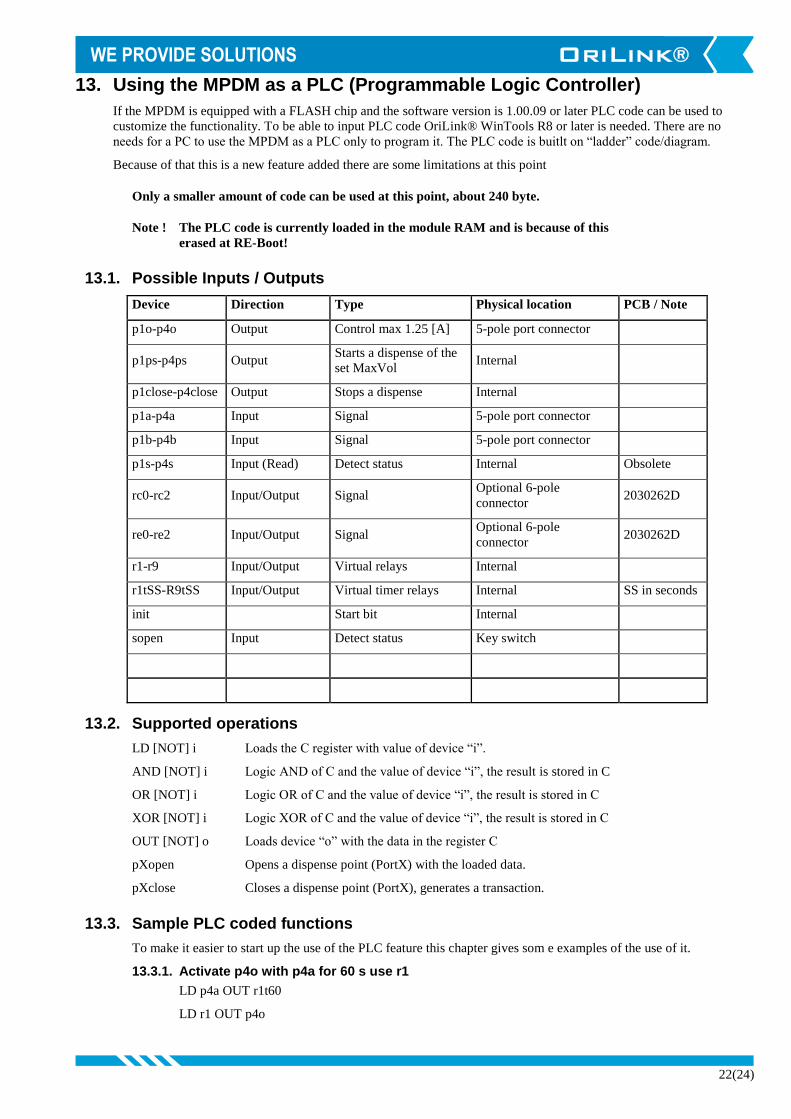
13. Using the MPDM as a PLC (Programmable Logic Controller)
If the MPDM is equipped with a FLASH chip and the software version is 1.00.09 or later PLC code can be used to
customize the functionality. To be able to input PLC code OriLink® WinTools R8 or later is needed. There are no
needs for a PC to use the MPDM as a PLC only to program it. The PLC code is buitlt on “ladder” code/diagram.
Because of that this is a new feature added there are some limitations at this point
Only a smaller amount of code can be used at this point, about 240 byte.
Note ! The PLC code is currently loaded in the module RAM and is because of this
erased at RE-Boot!
13.1. Possible Inputs / Outputs
Device Direction Type Physical location PCB / Note
p1o-p4o Output Control max 1.25 [A] 5-pole port connector
p1ps-p4ps Output Starts a dispense of the
set MaxVol Internal
p1close-p4close Output Stops a dispense Internal
p1a-p4a Input Signal 5-pole port connector
p1b-p4b Input Signal 5-pole port connector
p1s-p4s Input (Read) Detect status Internal Obsolete
rc0-rc2 Input/Output Signal Optional 6-pole
connector 2030262D
re0-re2 Input/Output Signal Optional 6-pole
connector 2030262D
r1-r9 Input/Output Virtual relays Internal
r1tSS-R9tSS Input/Output Virtual timer relays Internal SS in seconds
init Start bit Internal
sopen Input Detect status Key switch
13.2. Supported operations
LD [NOT] i Loads the C register with value of device “i”.
AND [NOT] i Logic AND of C and the value of device “i”, the result is stored in C
OR [NOT] i Logic OR of C and the value of device “i”, the result is stored in C
XOR [NOT] i Logic XOR of C and the value of device “i”, the result is stored in C
OUT [NOT] o Loads device “o” with the data in the register C
pXopen Opens a dispense point (PortX) with the loaded data.
pXclose Closes a dispense point (PortX), generates a transaction.
13.3. Sample PLC coded functions
To make it easier to start up the use of the PLC feature this chapter gives som e examples of the use of it.
13.3.1. Activate p4o with p4a for 60 s use r1
LD p4a OUT r1t60
LD r1 OUT p4o
23(24)
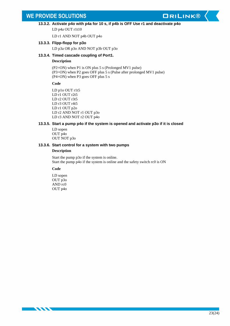
13.3.2. Activate p4o with p4a for 10 s, if p4b is OFF Use r1 and deactivate p4o
LD p4a OUT r1t10
LD r1 AND NOT p4b OUT p4o
13.3.3. Flipp-flopp for p3o
LD p3a OR p3o AND NOT p3b OUT p3o
13.3.4. Timed cascade coupling of Port1.
Description
(P2=ON) when P1 is ON plus 5 s (Prolonged MV1 pulse)
(P3=ON) when P2 goes OFF plus 5 s (Pulse after prolonged MV1 pulse)
(P4=ON) when P3 goes OFF plus 5 s
Code
LD p1o OUT r1t5
LD r1 OUT r2t5
LD r2 OUT r3t5
LD r3 OUT r4t5
LD r1 OUT p2o
LD r2 AND NOT r1 OUT p3o
LD r3 AND NOT r2 OUT p4o
13.3.5. Start a pump p4o if the system is opened and activate p3o if it is closed
LD sopen
OUT p4o
OUT NOT p3o
13.3.6. Start control for a system with two pumps
Description
Start the pump p3o if the system is online.
Start the pump p4o if the system is online and the safety switch rc0 is ON
Code
LD sopen
OUT p3o
AND rc0
OUT p4o
24(24)
14. Chip types.
From the start of OriLink® in 1997 all modules have been equipped with an OTP processor Microchip 16C67. OTP
means One Time Programmable. To day the flash technique has come to a point were we can use it for OriLink®.
Alentec & Orion AB has worked intensely since the summer 2004 to convert and enhance the software for OriLink®
modules to safely make use of the flash technology. The chip used is a Microchip 18F452.
In this development we have also made it possible to upgrade existing modules to use the flash technology by only
changing the chip combined with a simple reprogramming of the chip language.
14.1. Demands on a Non-PC system.
The only demand is that you must use a PC and a SIO (PC-interface 23 403) to reprogram the language of the
modules.
14.2. Demands on a PC system.
The PC must be running OriLink® WinTools R7 to make it possible to se the modules on the PC.
If the PC is running R6 it can easily be updated to R7.
Earlier versions must be replaced by R7, contact an Alentec & Orion representative for advice.
14.3. How to see the difference between chip types .
If a module is equipped with a flash chip it is shown by a yellow label on the chip.
14.4. What is the benefit of the flash chip.
No need for changing the chip for upgrading. The module software upgrade is a file you put on the hard drive of a
PC. The upgrading is then done through the OriLink® WinTools software package.
The flash chip used is faster and have more advanced features than the old chip. This gives the possibility to make
the modules more powerful.
The flash chip has about 4 times more software memory. gives the possibility to add more functions.