Embed Size (px)
Citation preview

IPDG-DXL100 Confidential
Chassis No. KF8-DXL10000
SERVICE MANUAL Multimedia Projector Model No. PDG-DXL100
Original Version
PRODUCT CODE1 682 347 81 REFERENCE NO. SM0946000

IIPDG-DXL100 Confidential
ContentsSERVICE MANUAL������������������������������������������������� IContents����������������������������������������������������������������������II Safety Instructions�������������������������������������������������III Safety Precautions �����������������������������������������������III Product Safety Notice�������������������������������������������III Service Personnel Warning���������������������������������IIIIntroduction���������������������������������������������������������� 1-1 Highlight�������������������������������������������������������������� 1-1 Compatible Mode������������������������������������������������1-3Disassembly Process�������������������������������������� 2-1 Equipment Needed & Product Overview������������������������������������������������2-1 Disassemble Filter��������������������������������������������� 2-2 Disassemble Lamp Cover Module����������������� 2-2 Disassemble Lamp Module����������������������������� 2-3 Disassemble Top Cover Module, Front Cover and Lens Cover������������������������� 2-3 Disassemble Keypad Board Module���������������2-5 Disassemble Zoom Ring Module�������������������� 2-5 Disassemble Top Shielding and FPC Cable������������������������������������������������� 2-6 Disassemble Main Board Module������������������� 2-6 Disassemble Lan Board Module ���������������������2-8 Disassemble Main Board Shielding�������������� 2-9 Disassemble Speaker��������������������������������������2-10 Disassemble Engine Module��������������������������2-10 Disassemble Color Wheel Module and Photo Sensor Board������������������������������ 2-11 Disassemble DMD Chip and DMD Board����2-11 Disassemble Rod Module������������������������������ 2-12 Disassemble LVPS Module�������������������������� 2-12 Disassemble Thermal Switch������������������������ 2-13 Disassemble Fan Module����������������������������� 2-13 Disassemble Blower Module������������������������� 2-14 Disassemble Lamp Driver Module��������������� 2-15 Disassemble Interlock Switch������������������������2-16 Disassemble Bottom Shielding��������������������� 2-16 Disassemble IO Cover and Bottom Cover Module������������������������������������ 2-17 Rod Adjustment������������������������������������������������ 2-18
Troubleshooting����������������������������������������������� 3-1 LED Lighting Message�������������������������������������� 3-1 Main Procedure�������������������������������������������������� 3-2 Electronic Function Block Diagram���������������� 3-6 Pin Assignment��������������������������������������������������� 3-7Function Test & Alignment Procedure�������� 4-1 Test Equipment Needed������������������������������������4-1 Service Mode������������������������������������������������������ 4-1 Factory Default & Lan Card Reset������������������4-1 Blower Reset������������������������������������������������������ 4-2 Test Condition����������������������������������������������������� 4-2 Test Inspection Procedure������������������������������� 4-4 PC MODE������������������������������������������������������������ 4-4 Video Performance�������������������������������������������� 4-7 PC Calibration��������������������������������������������������� 4-9 Optical Performance Measure��������������������� 4-10 Network Function Test�������������������������������������4-11 Others���������������������������������������������������������������� 4-14Firmware Upgrade�������������������������������������������� 5-1 Section 1: System Firmware Upgrade����������� 5-1 Equipment Needed�������������������������������������������� 5-1 DLP Composer Lite Setup Procedure����������� 5-2 Firmware Upgrade Procedure������������������������ 5-4 Section 2: 8051 Firmware Upgrade Procedure������������������������������������������� 5-8 Equipment Needed������������������������������������������� 5-8 NLINK Setup Procedure����������������������������������� 5-9 Manley USB Driver Upgrade Procedure����� 5-11 8051 Firmware Upgrade Procedure������������ 5-13 Section 3: Network Firmware ��������������������� 5-15 Upgrade Procedure���������������������������������������� 5-15 PC Hardware Link������������������������������������������� 5-16 Section 4: Lamp Driver Waveform Download������������������������������������������������������������5-18 Waveform Download��������������������������������������� 5-18Appendix A��������������������������������������������������������������� I Exploded Image������������������������������������������������������ IAppendix B�������������������������������������������������������������� II Serial Number System Definition����������������������� II PCBA Code Definition����������������������������������������� III

IIIPDG-DXL100 Confidential
Safety Instructions
Service Personnel Warning
Eye damage may result from directly viewing the light produced by the Lamp used in this equipment. Always turn off Lamp before opening cover. The Ultraviolet radiation eye protection required during this servicing.Never turn the power on without the lamp to avoid electric-shock or damage of the devices since the stabilizer generates high voltages (15kV - 25kV) at its starts.Since the lamp is very high temperature during units operation replacement of the lamp should be done at least 45 minutes after the power has been turned off, to allow the lamp cool-off.
WARNING:The chassis of this projector is isolated (COLD) from AC line by using the converter transformer. Primary side of the converter and lamp power supply unit circuit is connected to the AC line and it is hot, which hot circuit is identified with the line ( ) in the schematic diagram. For continued product safety and protection of personnel injury, servicing should be made with qualified personnel.
The following precautions must be observed.
1: An isolation transformer should be connected in the power line between the projector and the AC line before any service is performed on the projector.
2: Comply with all caution and safety-related notes provided on the cabinet back, cabinet bottom, inside the cabinet or on the chassis.
3: When replacing a chassis in the cabinet, always be certain that all the protective devices are installed properly, such as, control knobs, adjustment covers or
shields, barriers, etc.
DO NOT OPERATE THIS PROJECTOR WITHOUT THE PROTECTIVE SHIELD IN POSITION AND PR OPERLY SECURED.
4: Before replacing the cabinet cover, thoroughly inspect the inside of the cabinet to see that no stray parts or tools have been left inside.
Before returning any projector to the customer, the service personnel must be sure it is completely safe to operate without danger of electric shock.
Safety Precautions
Product Safety Notice
Product safety should be considered when a component replacement is made in any area of the projector. Components indicated by mark ! in the parts list and the schematic diagram designate components in which safety can be of special significance. It is, therefore, particularly recommended that the replacement of there parts must be made by exactly the same parts.

Confidential 1-1PDG-DXL 100
Chapter 1
Introduction
No Item Description
1 Technology ● 0.55” 2xLVDS super value XGA Type X DMD
2 Dimension (W x D x H) ● 306.5x120.5x292.3mm (Lens is included)
3 Weight ● 3.7 Kg (8.1 lbs)
4 Power Supply
● Universal AC 100-240V~ 50 / 60 Hz with PFC input ● 225W Lamp @ normal operation ● 170W Lamp @ eco operation ● Variance FAN speed control (Depend on temperature variance)
5 Keystone Correction ● +/ -15 degree Vertical
6 Resolution ● Native Resolution�� 1024�768Native Resolution�� 1024�768
7 Brightness ● 2700 ANSI Lumens
8 Contrast ● 750��1 (Full on/Full off)
9 Uniformity ● 80% (JBMA standard )
10 Throw ratio ● 0.609 distance / width
11 Projection lens ● F# 2.6 , Fixed Lens. f=6.97mm @ 77”
12 Lamp life
● 3,000 hours at typical full power mode (@ 225W, 60Hz)● 4,000 hours at Eco mode (@ 170W, 60Hz)(more than 50% of lamp population have light output >50% of initial min. Lumen output at the lamp life time)
13 Lens Offset ● 115%+/-5%
14 Video compatibility
● NTSC�� 3.58/4.43● PAL�� B/D/G/H/I/M/N● SECAM�� B/D/G/K/K1/L● HDTV�� 480i, 480p, 576i, 576p,720p, 1080i, 1080p480i, 480p, 576i, 576p,720p, 1080i, 1080p
1-1 Highlight

Confidential 1-2PDG-DXL 100
No Item Description
15 Terminals
● One Mini DIN 8-Pin Connector for RS232 control input● One 19-pin HDMI(V1.3) for Digital Video Data Input● One Mini DIN 4-pin for S-Video Input● One RCA Jack for Composite Video Input● One D-Sub 15-pin female connector for VGA output (Only for VGA 1)● Two D-Sub 15-pin female connector for VGA input (Stack) and component video input ● One RJ45 connector for Network Management● One 3.5 mm phone jack for audio input● One 3.5mm phone jack for variable audio output*Selectable cable control via either RS232 or RJ-45 LAN by OSD menu.
16 System Controller ● TI DDP2230
17 Color Wheel ● 40mm diameter, 5 segments (R80Y30G84W90B76) & 7200 rpm
18 Lamp ● 225W Lamp (Philips E20.9)
19 Temperature● Operating�� 5 ~ 35°C● Storage�� -20 ~ 60°C Storage�� -20 ~ 60°C
20 Altitude
● Operating�� 0 ~ 2,500 ft, for 5°C~35°C 2,500 ft ~ 5,000 ft, for 5°C~30°C 5,000 ft ~ 10,000 ft, for 5°C~25°C● Storage�� 40,000 ftStorage�� 40,000 ft
21 Input Signal
● Hsync Fre�uency 31.35 k ~ 79.98 k HzHsync Fre�uency 31.35 k ~ 79.98 k Hz● Vsync Fre�uency 50 ~ 75 Hz Vsync Fre�uency 50 ~ 75 Hz ● Video Signal RGB (PC) Video Signal RGB (PC) • Analog RGB 0.7Vp-p, 75 ohm, Separate TTL H,V Sync • Analog RGB 1Vp-p, 75 ohm, Sync. On Green signalAnalog RGB 1Vp-p, 75 ohm, Sync. On Green signal • Analog RGB 0.7Vp-p, 75 ohm, Composite TTL SyncAnalog RGB 0.7Vp-p, 75 ohm, Composite TTL Sync● Video Video • Composite video 1Vp-p, 75 ohmComposite video 1Vp-p, 75 ohm • S-video Luminance 0.714Vp-p, 75 ohmS-video Luminance 0.714Vp-p, 75 ohm • Chrominance 0.286Vp-p, 75 ohmChrominance 0.286Vp-p, 75 ohm • Component Video 1Vp-p, 75 ohmComponent Video 1Vp-p, 75 ohm

ConfidentialPDG-DXL 100 1-3
1-2 Compatible Mode
Computer Compatibility (Analog)
VGA Analog-PC SignalModes Resolution V-Sync [Hz] H-Sync [KHz]
VGA
640x480 60 31.50640x480 72 37.90640x480 75 37.50720x400 70 31.50
SVGA
800x600 56 35.20800x600 60 37.90800x600 72 48.10800x600 75 46.90832x624 75 49.725
XGA1024x768 60 48.401024x768 70 56.501024x768 75 60.00
SXGA1280x1024 60 63.981280x1024 75 79.98
WXGA1280x720 60 45.001280x800 60 49.7021440x900 60 55.935
QuadVGA 1280x960 60 59.70SXGA+ 1400x1050 60 63.98UXGA 1600 x 1200 60 75.00
Power Mac G4
640 x 480 66.6(67) 34.93800x600 60 37.90
1024x768 60 48.401152x870 75 68.68
PowerBook G4
640x480 60 31.35640x480 66.6(67) 34.93800x600 60 37.90
1024x768 60 48.401152x870 75 68.68
i Mac DV(G3) 1024 x 768 75 60.00

Confidential 1-4PDG-DXL 100
Computer Compatibility (Digital-HDMI)
(1) HDMI - PC SignalModes Resolution V.Sync [Hz] H.Sync [KHz]
VGA
640x480 60 31.5640x480 72 37.9640x480 75 37.5720x400 70 31.5
SVGA
800x600 56 35.2800x600 60 37.9800x600 72 48.1800x600 75 46.9832x624 75 49.725
XGA1024x768 60 48.41024x768 70 56.51024x768 75 60.00
SXGA1280x1024 60 63.981280x1024 75 79.98
WXGA1280x720 60 45.001280x800 60 49.7021440x900 60 55.935
Quad VGA 1280x960 60 59.7SXGA+ 1400x1050 60 63.98UXGA 1600x1200 60 75.00
Power Mac G4
640x480 66.6(67) 34.93800x600 60 37.9
1024x768 60 48.41152x870 75 68.68
PowerBook G4
640x480 60 31.35640x480 66.6(67) 34.93800x600 60 37.9
1024x768 60 48.41152x870 75 68.68
i Mac DV(G3) 1024x768 75 60.00

Confidential 1-5PDG-DXL 100
(2) HDMI - Video SignalModes Resolution V.Sync [Hz]480i 1440x480 60
480p (NTSC) 640x480 60480p (NTSC) 720x480 60
576i (PAL) 1440x576 50576p (PAL) 720x576 50
720p (NTSC) 1280x720 60720p (PAL) 1280x720 50
1080i (NTSC) 1920x1080 601080i (PAL) 1920x1080 50
1080p (NTSC) 1920x1080 601080p (PAL) 1920x1080 50
Note: If the Computer Compatibility supportive signal is different from User's Manual, please refer to User's Manual.

PDG-DXL100 Confidential 2-1
Chapter 2
Disassembly Process2-1 Equipment Needed & Product Overview
1. Screw Bit (+): 105
2. Screw Bit (+): 107
3. Screw Bit (-): 107
4. Hex Sleeves 5 mm
5. Tweezers
6. Projector
* Before you start: This process is protective level II. Operators should wear electrostatic chains.
* Note: - If you need to replace the main board, you have to record the lamp usage hour.

PDG-DXL100 Confidential 2-2
2-3 Disassemble Lamp Cover Module
1. Loosen 2 screws (as red circle) on the Lamp Cover.
2. Disassembled the Lamp Cover Module.
2-2 Disassemble Filter
1. Pull down the tenons (as red square) to disassemble the left filter.
2. Pull down the tenons (as yellow square) to disassemble the right filter.
3. Disassembled the left filter and the right filter.
The left filter The right filter

PDG-DXL100 Confidential 2-�
2-5 Disassemble Top Cover Module, Front Cover and Lens Cover
1. Unscrew 4 screws (as red circle) from the Bottom Cover.
2-4 Disassemble Lamp Module
1. Loosen 2 screws (as red circle) on the Lamp Module.
2. Pull out the Lamp Module.

PDG-DXL100 Confidential 2-�
2. Pull the Top Cover upward (as the yellow arrow direction) to disassemble top cover, front cover and lens cover.
Note: - When you disassemble the top cover, take care the FPC cable which connected Main Board and Keypad Board Module, please unplug the connector (as green square) from Keypad Board Module during pulling up.
- Avoid damaging by pulling keypad FPC cable.
- Please hold the lens cover when disassemble the top cover to avoid damaging the lens (as picture A shown).
- Make sure the FPC cable plug into the correct ports when assembling it.
3. Disassembled the Lens Cover, Front Cover and Top Cover Module.
A

PDG-DXL100 Confidential 2-5
2-7 Disassemble Zoom Ring Module
1. Unscrew 3 screws (as red circle) from the Top Cover Module.
2. Remove the Zoom Ring Module.
2-6 Disassemble Keypad Board Module
1. Unscrew 4 screws (as red circle) to disassemble the Keypad Board Module from the Top Cover Module.
2. Separate mylar, keypad board and keypad.
3. Tear off 2 EMI gaskets (as green square).
Zoom Ring Module
Keypad

PDG-DXL100 Confidential 2-�
2-8 Disassemble Top Shielding and FPC Cable
1. Unscrew 11 screws (as red circle).
2. Tear off EMI tapes (as yellow square).
�. Remove the Top Shielding.
4. Unplug 1 connector (as green square) to disassemble the FPC cable.
Top Shielding
2-9 Disassemble Main Board Module
1. Unscrew 2 screws (as blue circle).
2. Unscrew 6 hex screws (as green circle).
3. Unscrew 2 screws (as red circle).
FPC Cable

PDG-DXL100 Confidential 2-7
4. Unplug 5 connectors (as yellow square).
Note: - Make sure cables plug into the correct ports when assembling the unit.
Please refer to the below table details of each connector on Main Board.
Item Male Connector on Main Board The key feature Figure
A Photo Sensor Compose of Red/Black/White Wire and Black wire tube (3 pin)
B Blower Compose of Red/White/Black Wire and Blue wire tube (3 pin)
C Fan Compose of Red/Black/Yellow Wire (3 pin)
D Speaker Compose of Red/Black Wire and Black wire tube (2 pin)
E Lamp Driver Black wire tube (5 pin)
EDCBA

PDG-DXL100 Confidential 2-�
5. Unplug 1 connector (as orange square)
�. Disassembled the Main Board Module.
2-10 Disassemble Lan Board Module
1. Unscrew 1 screw (as green circle) to disassemble the Lan Board Module.

PDG-DXL100 Confidential 2-�
2. Tear off black mylar (as yellow square) and sponge (as red square).
3. Tear off two black rubbers (as green square).
2-11 Disassemble Main Board Shielding
1. Unscrew 3 screws (as red circle) to disassemble the main board shielding.
2. Disassembled the Main Board Shielding.

PDG-DXL100 Confidential 2-10
2-13 Disassemble Engine Module
1. Unscrew 6 screws (as red circle) to disassemble the Engine Module.
2. Remove the Engine Module.
2-12 Disassemble Speaker
1. Unscrew 2 screws (as red circle) to disassemble the speaker module.
2. Tear off the black mylar (as yellow square).
3. Separate the speaker rubber and speaker.

PDG-DXL100 Confidential 2-11
2-14 Disassemble Color Wheel Module and Photo Sensor Board
1. Unscrew 2 screws (as red circle) to disassemble the Color Wheel Module.
2. Unscrew 1 screw (as yellow circle) to disassemble the Photo Sensor Board from the Color Wheel Module.
Note: - Avoid touching the glass parts of color wheel.
2-15 Disassemble DMD Chip and DMD Board
1. Unscrew 2 screws (as red circle) to disassemble the Heat Sink and DMD Module.
2. Counterclockwise rotate the screw (as yellow circle) to disassemble the DMD Board and DMD Chip.
Note: - Avoid touching the DMD Chip when you disassemble it.
- Found that the DMD Chip has scrapes or dirt use of a magnifying glass, you may use an electrostatic ion gun to clean it.
- Pay attention to the fixed position when assembling the DMD Chip.

PDG-DXL100 Confidential 2-12
2-16 Disassemble Rod Module
1. Unscrew 2 screws (as green circle) to disassemble the Rod Spring (a).
2. Unscrew 1 screw (as yellow circle) to disassemble the Rod Cover (b).
3. Disassemble the Rod(c).
Note: - Avoid touching the Rod when you disassemble or assemble it.
- Please notice the Rod Module’s direction when you assemble it (as picture A shown).
- Ensure left edge of Rod Module contact with the Engine base’s blocks (as picture A blue square shown).
- Rod Spring must hook in the position (as picture B shown).
A B
c
ba
2-17 Disassemble LVPS Module
1. Tear off the mylar (as green square).
2. Unscrew 6 screws (as red circle).
3. Unplug 1 connector (as yellow square).
4. Unplug 2 connectors (as blue square) to take off the LVPS Module and the AC Inlet Bracket.
5. Unplug 1 connector (as red square).
6. Disassembled the LVPS. AC Inlet Bracket
LVPS

PDG-DXL100 Confidential 2-1�
2-18 Disassemble Thermal Switch
1. Unscrew 1 screw (as red circle) to disassemble the Thermal Switch.
2. Disassembled the Thermal Switch.
2-19 Disassemble Fan Module
1. Unscrew 4 screws (as red circle) to disassemble the Fan Module.
2. Unscrew 4 screws (as blue circle) to separate the Fan and Fan Shielding.

PDG-DXL100 Confidential 2-1�
2-20 Disassemble Blower Module
1. Unscrew 3 screws (as red circle) to disassemble the Blower Module.
2. Seprate the Blower and Blower Rubber.
Note: - Take the Fan Module as the right gesture.
Fan Shielding
The right gesture The wrong gesture

PDG-DXL100 Confidential 2-15
2-21 Disassemble Lamp Driver Module
1. Unscrew 1 screw (as red circle) to disassemble the Lamp Driver Module.
2. Unscrew 4 screws (as green circle).
3. Unplug 3 connectors (as yellow square).
4. Separate the Lamp Driver Holder and Lamp Driver .
5. Disassembled the cables.
Lamp Driver Holder Lamp Driver

PDG-DXL100 Confidential 2-1�
2-22 Disassemble Interlock Switch
1. Unscrew 1 screw to disassemble the Interlock Switch.
2. Disassembled the Interlock Switch.
2-23 Disassemble Bottom Shielding
1. Unscrew 3 screws to disassemble the Bottom Shielding.
2. Disassembled the Bottom Shielding.
Bottom Shielding

PDG-DXL100 Confidential 2-17
2-24 Disassemble IO Cover and Bottom Cover Module
1. Unscrew 3 screws (as red circle).
2. Separate the IO Cover and Bottom Cover Module.

PDG-DXL100 Confidential 2-1�
3. Abnormal image inspection
- It should not have any abnormal color at the rim of the image by estimating through the eyes.
Note: - To avoid over adjusting the rod.
- After the opreation, please use the glue to fix the screws.
- Please use Z type driver to adjust Rod screw 1.
2-25 Rod Adjustment
1. Environment Adjustment
- The distance between the engine and the screen is 0.74 M.
- This process should be done at a dark environment (under 2 Lux).
2. Procedure Adjustment
- Change the screen to “white screen”.
- Adjust the screws(as red circle) to revise the image.
(“screw 1” should be adjusted first, and then “screw 2”. Adjust until the yellowish or bluish parts disappeared.)
Z type driver
screw2screw1

PDG-DXL100 Confidential 3-1
Chapter 3
Trobleshooting
MessagePower LED Temp LED
(Red)Lamp LED
(Red)(Red) (Green) (Orange)
Standby (Input power cable)
Normal (Power on)
Powering up (Warming up) Flashing
Power off (Cooling-I: It can’t
accept any key at this status)
Flashing
Power off (Cooling-II: It can
accept power key to turn on the projector)
Flashing
Error (Lamp failed)
Error (Fan lock) Flashing
Error (Over temp.)
3-1 LED Lighting Message
No lightSteady light When LED light on after 5 sec., go to standby mode.

PDG-DXL100 Confidential 3-�
3-2 Main Procedure
No Symptom Procedure
1 No Power
- Ensure the Power Cord and AC Power Outlet are securely connected
- Ensure all connectors are securely connected and aren’t broken
- Check LVPS
- Check Lamp Driver
- Check Main Board
� Auto Shut Down
- Ensure the projector is not put on a soft pad and the air vent is not blocked- Check LED Status
a. Lamp Failed: Power LED (lights red), Lamp LED (lights red, when LED light on after 5 sec., go to standby mode) - Check Lamp
- Check Lamp Driver
- Check Main Board
b. Over Temp.: Power LED (lights red), Temp LED (lights red)
- Clean air filters
- Check Fan
- Check Thermal Switch
- Check Main Board
c. Fan Lock: Power LED (lights red), Temp LED (Flashes red)
- Check Fan
- Check Main Board

PDG-DXL100 Confidential 3-3
No Symptom Procedure
3 No Light On
- Ensure all connectors are securely connected and aren’t broken
- Check Lamp Cover
- Check Interrupt Switch
- Check Lamp Driver
- Check LVPS
- Check Main Board
- Check Color Wheel
- Check Photo Sensor Board
4 No Image
- Ensure the Signal Cable and Source work (If you connect multiple sources at the same time, use the “Input” button switch)
- Ensure all connectors are securely connected and aren’t broken
- Check Main Board
- Check DMD Board
- Check DMD Chip
- Check Color Wheel
- Check Engine Module
5 Mechanical Noise- Check Color Wheel
- Check Fan Module
6 Line Bar/Line Defect
- Check if the Main Board and the DMD Board are assembled properly
- Check Main Board
- Check DMD Board
- Check DMD Chip

PDG-DXL100 Confidential 3-4
No Symptom Procedure
7 Image Flicker
- Do “Factory default” of the OSD Menu
- Ensure that the signal cables and source are work as well
- Check Lamp Driver and waveform
- Check Lamp Module
- Check Color Wheel
- Check Photo Sensor and clean Photo Sensor
- Check DMD Board
- Check Main Board
8 Color Abnormal
- Do “Factory default” of the OSD Menu
- Adjust Color Wheel Index
- Check Main Board
- Check DMD Board
- Check Color Wheel
9 Poor Uniformity/Shadow
- Ensure the projection screen without dirt
- Ensure the projection lens is clean
- Measure Brightness under “Bright” mode. Ensure the Brightness is within spec(please refer to 4-9 Optical Performance Measure for how to get into “Bright” mode.)- Check rod alignment
- Check Engine Module
10 Dead Pixel/Dust(Out of spec.)
- Ensure the projection screen without dirt
- Ensure the projection lens is clean
- Clean DMD Chip and Engine Module
- Check DMD Chip
- Check Engine Module
11 Garbage Image
- Ensure that the signal cables and source work as well
- Check Main Board
- Check DMD Board

PDG-DXL100 Confidential 3-5
No Symptom Procedure
1� Remote Control/ Control Panel Failed
- Remote Control
a. Check Battery
b. Check Remote Controller
c. Check Keypad Board
d. Check Main Board
- Control Panel
a. Check FPC
b. Check Keypad Board
c. Check Main Board
13 Function Abnormal
- Do “Factory default” of the OSD Menu
- Check Main Board
- Check DMD Board
14 Audio Abnormal
- Ensure that the signal cables and source are work as well
- Ensure that your Projector is not in “Mute” mode
- Check the interior Speaker of the projector
- Check the exterior Speaker that you are using
- Check Main Board
15 Network Function Abnormal
- Ensure RJ45 Connector work well (Normal Status: Before joining RJ45 line,Orange LED flashes; after joining RJ45 line,and Internet transmission speeds over 100MB/ second,Green LED will light.)
- Check Internet Source and LAN Module Board if LED message is in abnormal status
- Check Main Board if LED message is in normal status
16 Forget Password
- If the user forget the projector’s password, executing below steps can solve the problem: (1) Power on the projector. (2) Get into service mode (please refer to 4-2 for details) (3) Select “factory reset”. click “enter” button. (4) The “security settings” in OSD menu will change to “OFF”in OSD menu will change to “OFF” will change to “OFF” and user can use the default password (1234) to set new password .

PDG-DXL100 Confidential 3-6
3-3 Electronic Function Block Diagram

PDG-DXL100 Confidential 3-7
3-4 Pin Assignment

PDG-DXL100 Confidential 4-1
Chapter 4
Function Test & Alignment Procedure
4-1 Test Equipment Needed
- IBM PC with HDTV resolution
- DVD player with Multi-system, equipped “Component”, “Composite”, “S-Video” and “HDMI”.
- HDTV Source (720P,1080P,1080i)
- Minolta CL-100
- Quantum Data 802B or CHROMA2327 (Color Video Signal & Pattern Generator)
4-2 Service Mode
1. Turn on the projector
2. Press “Power”, “Enter”, “Enter” and “Menu” button sequentially to get into service mode.
4-3 Factory Default & Lan Card Reset
After final QC step, we have to erase all saved change again and restore the default setting: 1. Factory Default (1) Please get into OSD menu.
(2) Execute “Factory Default” function under “Setting”.
2. Lan Card Reset
(1) Get into Service mode.
(2) Select “Lan Card Reset”, click “Enter” to restore all lan card setup to its factory default settings.

Confidential 4-2PDG-DXL100
4-4 �lo�er Reset�lo�er Reset After replace main board/blower or upgrade system FW, you need to do: (1) Get into Service Mode. (2) Slesct “Blower Factory RPM”, then click “Enter” button. Note: The steps must be finished in a minute after powering on projector.
4-5 Test Condition- Circumstance brightness: Dark room less than 2 lux.
- Inspection distance: 0.5m~1.0m functional inspection.
- Screen size: 60 inches diagonal.
- After repairing each unit, a Run-in test is necessary (refer to the below table).
Symptom Run-in TimeNormal repair 2 hoursNFF 4 hoursAuto shutdown 6 hours
- Get into Burn-In Mode* Cycle setting is based on the defect symptoms. ie: If it is NFF, the run-in time is 4 hours. You have
to set the lamp on for 50 min. and lamp off for 10 min for 4 cycles.
Press power > Enter > Enter > Menu to get into service modeChoose Burn-In Test > enterLamp On Press right key to adjust the time (50)Lamp Off Press right key to adjust the time (10)Set burn in cycle Press right key to adjust the cycleAfter setting up the time, choose “Get into Burn-In Mode” and press enter

Confidential 4-3PDG-DXL100
Order Symptom Pattern Criteria1 Bright pixel Gray 10 pattern A+B=0
2 Dark pixel White pattern A+B≤6
3 Unstable pixel White&Black pattern A+B≤1
4 Adjacent pixels White&Black pattern A+B=0
5 Dark blemish Blue 60 patternA+B≤10
(diameter <1 inch)
6 Bright blemish Gray 15 patternA+B≤10
(diameter <1 inch)
7 Bright dots on frame Gray 10 pattern 1
Defect specification table
< Figure: Zone A, Zone B & Frame(as green line) Definition, Active area=Zone A+ Zone B >
Screen Defects (While replacing DMD Chip, DMD �oard and Main �oard)
Frame

Confidential 4-4PDG-DXL100
4-6 Test Inspection Procedure
Update
Change parts
Main Board Firmware Color
WheelLamp
ModuleEngine Module
Lan Module Board
Lamp Driver Blower
Version Update v vColor Wheel Index v v
PCCalibration v v
Reset lamp hour vFactory Default v vRod adjustment v vLan Card Reset v
Waveform Download vBlower Reset v v v
Note 1: If Color appears abnormal after changing Main Board Module, please do Color Wheel index adjustment.
Note 2: After final QC step, OSD Reset & Lan card Reset need to be done.
4-7 PC MODE
1. Frequency and tracking boundary
Procedure - Test equipment: video generator. - Test signal: analog 1024 x 768@60Hz - Test Pattern: general-1 or master - Check and see if the image sharpness is well performed. - If not, re-adjust by the following steps: (1) Select “Frequency” function to adjust the total
pixel number of pixel clock in one line period. (2) Select “Tracking” function and use right or left
arrow key to adjust the value to minimize video flicker.
- Adjust Resync or Frequency/Tracking/H. Position/V. Position to the inner screen.
Inspection item - Eliminate visual wavy noise by Resync, Frequency or Tracking selection.
Master
General-1

Confidential 4-5PDG-DXL100
- Check if there is noise on the screen. - Horizontal and vertical position of the video
should be adjustable to the screen frame.Criteria - If there is noise on the screen, the product is con-
sidered as failure product. - If there is noise on the screen, use auto or man-
ual “frequency” function or “tracking” function to adjust the screen.
- The PC mode functionally sure be workable include support format with frequency and auto detected functional will be workable.
2. �right Pixel
Procedure - Test equipment: video generator. - Test signal: analog 1024 x 768@75Hz - Test Pattern: gray 10Inspection item - Bright pixel check. Criteria - Bright pixel is unacceptable in the active zone; 1
pixel is allowed on the frame. - Ref. Defect specification table
3. Dark Pixel
Procedure - Test equipment: video generator. - Test signal: analog 1024 x 768@75Hz - Test Pattern: full whiteInspection item - Dead pixels check. - White pattern (IRE=100)Criteria - The dark pixel is unacceptable in Zone A under
full white pattern; other area can accept no more than 6 dark pixels.
- Adjacent pixels are unacceptable. - Ref. Defect specification table
Full white
Gray 10

Confidential 4-6PDG-DXL100
4. �right �lemish
Procedure - Test equipment: video generator. - Test signal: analog 1024 x 768@75Hz - Test Pattern: gray 15Inspection item - Bright blemish check. Criteria - The bright blemish should be no more than 10 under gray 15 pattern. - Ref. Defect specification table
5. Dark �lemish
Procedure - Test equipment: video generator. - Test signal: analog 1024 x 768@75Hz - Test Pattern: blue 60Inspection item - Dark blemish check Criteria - The dark blemish should be no more than 10 under blue 60 pattern. - Ref. Defect specification table
6. Focus Test
Procedure - Test equipment: video generator. - Test signal: analog 1024 x 768@75Hz - Test Pattern: full screen Inspection item - Focus checkCriteria - From screen 0.74 M via visual to check the focus,
look at the entire screen, focus shall be clear, crisp, and sharp over the entire surface of the display pattern. (Blur word on one of the corner after adjustment is acceptable. However, the word should at least be recognizable.)
7. Color Performance
Procedure - Test equipment: video generator. - Test signal: 1024 x 768@75Hz, 1080P
Blue 60
Full screen
Gray 15

Confidential 4-7PDG-DXL100
- Test Pattern: Master, 64 gray RGBW * Please Use 1024 x 768@75Hz signal & 64
gray RGBW pattern and 1080P signal & master pattern to do color performance test. Color can not discolor to purple and blue.
Inspection item - Check if each color level is well-functioned. - Color saturation Criteria - Screen appears normal. It should not have any
abnormal condition, such as lines appear on the screen and so on.
- Color appears normal. - It is unacceptable to have few lines flashing. - RGBW should all appear normal on the screen
and sort from R -G-B-W. - Color levels should be sufficient and normal.
(The unidentified color levels on both left and right sides should not over 4 color levels.)
- Gray level should not have abnormal color or heavy lines.
- If color appears abnormal, please get into service mode to do color wheel index adjustment.
4-8 Video Performance
1. CV�S
Procedure - Test equipment: DVD player - Test signal: CVBSInspection item - Video performance testInspection Distance - 0.5M ~1.0M Criteria - Check any abnormal color, line distortion or any
noise on the screen.
Motion video
Master
64 gray RGBW

Confidential 4-8PDG-DXL100
2. HDTV/ Component
Procedure - Test equipment: DVD player - Test signal: Ycbcr/YPbPr Inspection item - HDTV performance testInspectionDistance - 0.5M ~1.0MCriteria - Check any abnormal color, line distortion or any
noise on the screen.
3. HDMI Test
Procedure - Test equipment: DVD Player with HDMI output. - Test signal:1080pInspection item - HDMI performance test.Inspection Distance - 0.5M ~1.0M.Criteria - Ensure the image is well performed and the color can not discolor. - Check the audio is normal or not.
4. Audio Test
Procedure - Test equipment: DVD Player - Test signal: CVBSInspection item - Audio performance testInspection Distance - 0.5 M ~1.0 MCriteria - Check the sound from speaker - Plug Audio cable into Audio in port, check whether “Volume” is normal. - Plug Audio cable into Audio Out port, check whether the outboard speaker’s “Volume” is normal. - Adjust the volume to “0→ 9” by using the remote controller. - Check the sound from speaker. - Check whether the “mute” is normal.

Confidential 4-9PDG-DXL100
White/Black
5. S-Video
Procedure - Test equipment: DVD player - Test signal: S-VideoInspection item - Video performance testInspection Distance - 0.5 M ~1.0 M Criteria - Check any abnormal color, line distortion or any noise
on the screen. - Check the sound from speaker.
4-9 PC Calibration
Procedure - Test equipment: video generator - Once Main Board is changed,PC calibration should be done as well. (1) Test signal: 1024 x 768@60Hz (2) Test Pattern: White/Black - Note (1) Calibration pattern should be in full screen mode. (2) Please refer to 4-2 Guide to get into service mode and choose “PC calibration”.Inspection item - Check if there is lines on the screen. - Check if there is noise on the screen. - Horizontal and vertical position of the video should be
adjustable to the screen frame.Criteria - If there is noise on the screen, the product is
considered as failure product. - The screen appears normal, it shouldn’t appear any abnormal condition, such as lines and so on. - Check if the projection is same as monitor diplayed.

Confidential 4-10PDG-DXL100
4-10 Optical Performance Measure
Inspection Condition- Environment luminance: 2 Lux
- Product must be warmed up for 5 minutes
- Distances from the screen: 0.74 M
- Screen Size: 60 inches diagonal
1. Test equipment
Procedure - Please get into OSD menu,Select “Bright” mode” mode mode under “Image”.”.. - Test equipment: video generator. - Test signal: analog 1024 x 768@60Hz
2. �rightness
Procedure - Full white pattern - Use CL100 to measure brightness values of P1~P9. - Follow the brightness formula to calculate brightness values. ☼ Brightness Formula Avg. (P1~P9)*1.1mAvg. (P1~P9)*1.1m2 Criteria • 1150 ANSI lumen
3. Full On/Full Off Contrast
Procedure - Full white pattern & Full black pattern - Use CL100 to measure brightness values of full white pattern P5 & full black pattern B5 ( see image: full white) - Follow Contrast formula to calculate contrast values. ☼ Contrast Formula P5/B5 Note: P5 = Lux of center in full white pattern B5 = Lux of center in full black pattern
Full white pattern
Full black pattern
Confidential 4-11PDG-DXL100
Criteria • 600:1
4. Uniformity
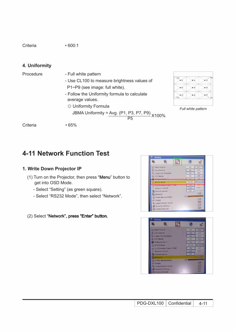
Procedure - Full white pattern - Use CL100 to measure brightness values of P1~P9 (see image: full white). - Follow the Uniformity formula to calculate average values. ☼ Uniformity Formula JBMA Uniformity = Avg. (P1, P3, P7, P9) P5 Criteria • 65%
Full white pattern
X100%
4-11 Net�ork Function Test
1. Write Do�n Projector IP
(1) Turn on the Projector, then press “Menu“MenuMenu” button to get into OSD Mode. - Select “Setting” (as green square). - Select “RS232 Mode”, then select “Network”.
(2) Select “Network”, press “Enter” button.“Network”, press “Enter” button.Network”, press “Enter” button.”, press “Enter” button., press “Enter” button.“Enter” button.Enter” button.” button. button.

Confidential 4-12PDG-DXL100
A
� (4) The image B will appear on the screen. - Key in the IP address: 192.168.0.100. - Key in the Subnet mask: 255.255.255.0.
(5) The image C will appear on the screen, please wait a moment.
(6) The image D will appear on the screen, please wait a moment.
C
D
(3) The image A will appear on the screen, please wait a moment.

Confidential 4-13PDG-DXL100
2. Net�ork Setting
(1) Open the “Local area connection”,(1) Open the “Local area connection”,“Local area connection”,Local area connection”,”,, choose “properties”.“properties”.properties”.”..
(2) Select “Internet protocol (TCP/IP)”, then click “Properties”.
(3) Modify the IP address to 192.168.0.99, and modify Subnet mask to 255.255.255.0. Note: - The HOST ID (192.168.0.XXX) of PC IP address must be different from the projector IP address written down in step 1 of 4-11-1.
(4) Click “OK”.

Confidential 4-14PDG-DXL100
4-12 Others
1. Functional Inspection
Keypad button - All keypad buttons must operate smoothly.
Remote Controller - Check whether the remote controller can work normal, “Menu”, “Left” and “Right” buttons work smoothly.
General - All OSD functions must be checked for functionality. When OSD menu is displayed, there shall be no visible peaking, ringing, streaking, or smearing artifacts on the screen.
Factory Default - The factory settings (with appropriate centering, size, geometry distortion, etc.) shall be displayed upon “Recall” is selected from OSD.
(5) Click “Close” to quit the setting screen.“Close” to quit the setting screen.Close” to quit the setting screen.” to quit the setting screen. to quit the setting screen.3. Read Projector Information
(1) Connect the PC and the Projector with LAN Cable. (2) Execute “Internet Explorer”.“Internet Explorer”.Internet Explorer”.”.. (3) Visit the IP address: “http://192.168.0.100/”.“http://192.168.0.100/”.http://192.168.0.100/”.”.. - Key in “User Name: Administrator” and “Password:“User Name: Administrator” and “Password:User Name: Administrator” and “Password:” and “Password: and “Password:“Password:Password: admin”, click “Login” to get into Projector Web Server.”, click “Login” to get into Projector Web Server., click “Login” to get into Projector Web Server.“Login” to get into Projector Web Server.Login” to get into Projector Web Server.” to get into Projector Web Server. to get into Projector Web Server. (4) Projector information will be shown on the screen. - Please check whether web management, FW version and model name are right.

Confidential 4-15PDG-DXL100
Display Size - All preset modes shall expand to full screen size using OSD Horizontal and Vertical Size controls.
Display Data Channel (DDC) - The purpose of the DDC test is to verify the DDC1/DDC2B operation of the projector and to verify Plug & Play function.
Acoustic - High pitch sound from cooling fan and color wheel is unacceptable.
2. Check points for exterior and print pattern
Check item Check point
Text & Pattern Missing letters & pattern or blurry prints are unacceptable.
Exterior Dirt, scrape, water ripples and uneven color are unacceptable.
Zoom ring Zoom ring is functioning smoothly.
Logo Missing logo, missing prints and blurry prints are unacceptable
Screw All screws sure be fixed and in right type.Pedestal Well-functionedLamp Cover It should be locked in the correct place.Plastic Parts All plastic parts can not be broken and damaged.Safety or warning label
All safety and warning labels should be visible, including all contents.
Connector All interface connectors should be complete and workable.

PDG-DXL100 Confidential 5-1
Chapter 5
Firmware Upgrade
Section 1: System Firmware Upgrade
5-1-1 Equipment Needed
Software: (DDP 2230- RS232)- DLP Composer Lite 8.3
- Firmware
- Library file (library file has to put in PC and set right path in 5-1-3 step 4)
Hardware: - Projector
- Power cord: CH4200105G011 (US Type)
CH4200120G011 (EU Type)
CH4200110G011 (UK Type)
- RS232 cable (DSUB(F) 9 – DIN(M) 8)
- PC or Laptop

PDG-DXL100 Confidential 5-2
5-1-2 DLP Composer Lite Setup Procedure
1. Choose "DLP Composer Lite V8.3 Setup" Program.
2. Click "Next".
3. Read "License Agreement".
- Choose "I accept and agree to be bound by all the terms and conditions of this License Agreement".
- Click "Next".
4. Click "Next".

PDG-DXL100 Confidential 5-3
5. Click "Browse" button to change the"Browse" button to change theBrowse" button to change the" button to change the button to change the downloading location to “program files”, then click "Next".click "Next".
6. Click "Next".
7. The program is executing "installing" status.
8. Click "Finish".

PDG-DXL100 Confidential 5-4
5-1-3 Firmware Upgrade Procedure
1. Set-up
- Hold on "Power" and "Menu" buttons, then plug in the power cord, the power LED will go to steady orange, the Temp LED and Lamp LED will go to steady red.
- Loosen the two buttons.
- Connect projector with PC by RS232 cable.
Note: The system fan and the lamp will not operated.
2. Execute the "DLP ComposerTM Lite 8.3" file.
3. Click "Edit" and "Perferences".
RS232 port
Power port
Power button
Menu button
Temp LEDLamp LED
Power LED

PDG-DXL100 Confidential 5-5
4. Click "Library".
- Click the "Browse" and navigate to the directory where you put the DLP Composer installation files in.
- Click "Library v8.3" folder.
- Click "OK".
5. Click "Communications".
- Select "Serial Port".
- Select the COM Port which you are using.
- Click "Configure".
6. "Serial Port Configuration" picture will appear on the screen.
- Make sure the settings are as below:
(1) In "Baud Rate" item, select "115200".
(2) In "Data Bits" item, select "8".
(3) In "Stop Bits" item, select "1".
(4) In "Parity" item, select "None".
(5) In "RTS" item, select "Enable".
(6) In "CTS" item, select "Disable".
(7) Key in "6000" into "Read" and "Write" items of "Timeouts (in milliseconds)".
- Click "OK".
7. Click "OK".

PDG-DXL100 Confidential 5-�
8. Choose "Flash Loader".
- Click "Browse" to search the firmware file (*.img).
- Click "Open".
9. Select "Complete Image Download", then select "Skip Boot Loader Area". (select "32KB").
- Click "Reset Bus" to erase the flash memory.
10. If the FW is ready, click "Start Download" to execute the firmware upgrade.
- Click "Yes".
11. Proceeding Picture.

PDG-DXL100 Confidential 5-�
12. It takes about several minutes, the firmware upgrade process is finished, "Download completed" will appear on the screen.
- Unplug RS232 cable and power cord.
13. Check FW version.
- Re-plug in power cable, then restart the unit and get into the Service mode to check the firmware version.
(To get into Service mode, please press "Power", "Enter", "Enter" and "Menu" buttons sequentially.)
PDG-DXL100 Confidential 5-8
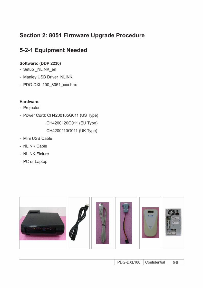
Section 2: 8051 Firmware Upgrade Procedure
5-2-1 Equipment Needed
Software: (DDP 2230)- Setup _NLINK_en
- Manley USB Driver_NLINK
- PDG-DXL 100_8051_xxx.hex
Hardware: - Projector
- Power Cord: CH4200105G011 (US Type)
CH4200120G011 (EU Type)
CH4200110G011 (UK Type)
- Mini USB Cable
- NLINK Cable
- NLINK Fixture
- PC or Laptop

PDG-DXL100 Confidential 5-9
5-2-2 NLINK Setup Procedure
1. Choose "setup_NLINK_en.exe" program.
2. Click "Next".
3. Click "Next".
4. Click "Next".

PDG-DXL100 Confidential 5-10
5. Click "Next".
- Select the additional task that you may create a desktop icon.
6. Click "Install" to begin installing NLINK Procedure.
7. Click "Finish".
- Complete the NLINK setup.
8. "MCU Choose" picture will appear on the screen.
- Close the picture.

PDG-DXL100 Confidential 5-11
(1)
(3)
(2)
5-2-3 Manley USB Driver Upgrade Procedure
Note: - If you have installed the Manley USB driver, there is no need to perform this action.
1. Set up
- Plug in the power cord.
- Connect VGA-1 Port of projector with NLINK Fixture.
- Connect NLINK Fixture with PC by USB cable.
2. Execute Program
(1) "Found New Hardware Wiszard" picture will appear on the screen.
(2) Select "Install from a list or specific location (Advanced)".
(3) Click "Next".
(4) Select "Include this location in the search", then click "Browse".
(5) "Browse For Folder" picture will appear on the screen.
(6) Select "TPRP1" folder in the "Manley USB Driver_N-Link" folder, then click "OK".
(4)
(6)
(5)
VGA-1 port

PDG-DXL100 Confidential 5-12
(7) Click "Next".
(8) Click "Continue Anyway".
(9) Click "Browse".
(10) Select the file "slabser.sys", then open it.
(7)
(8)
(9)
(10)

PDG-DXL100 Confidential 5-13
(11)
5-2-4 8051 Firmware Upgrade Procedure
1. Execute 8051 FW Program
- Double click "NLINK V1.2" to execute NLINK program.
Note: - When we execute NLINK program, the Power LED flashes orange and Fixture LED flashes red.
2. Choose the right type of MCU
- "MCU Choose" picture will appear on the screen, select "W79E804".
- Click "OK".
(11) Click "Finish".
- "Manley TPRP1-Protocol Emulator" will appear on the picture.
- Complete the USB Driver Upgrade Procedure.
Note: - If "Found New Hardware Wiszard" picture appear again, repeat step 2 to install USB Drivier.

PDG-DXL100 Confidential 5-14
3. Choose 8051 file (*.hex)
- "Manley Nlink" picture will appear on the screen.
- Ensure "MCU" is the one you chose in the last step (as green square).
- Click "Open".
- Select the 8051 file where you put the file in, then click "Open".
4. Program settings
- Ensure NLlNK Fixture and PC are securely connected: the indicator lights on green, and the state is "Connect" (as blue square).
- Select "4MHz-20MHz Crystal" and "Brownout detect voltage is 3.8" (as green square).
- Click "Erase/Write(W)" (as red ellipse) to execute 8051 FW upgrade.
5. Finish
- When 8051 FW upgrade process is finished, "Write Chip success" will be shown (as red square).
6. Check 8051 FW version
- Turn on the unit and get into the service mode to check the 8051 FW version.
(To get into Service mode, please press "Power", "Enter", "Enter" and "Menu" buttons sequentially.)

PDG-DXL100 Confidential 5-15
Section 3: Network Firmware Upgrade Procedure
5-3-1 Equipment Needed
Software: - PDG-DXL 100_LAN Module FW_xxx.bin (*.bin)
Hardware: - Projector
- Power Cord: CH4200105G011 (US Type)
CH4200120G011 (EU Type)
CH4200110G011 (UK Type)
- LAN Cable
- PC

PDG-DXL100 Confidential 5-1�
5-3-2 PC Hardware Link
1. Execute Network Settings, please refer to 4-11 details of Chapter 4.
2. Double click "Internet Explorer".
3. Visit "http:// 192.168.0.100/tgi/fu.tgi" to get into Firmware Update screen.
Note: - The format of address for FW update is "IP address/tgi/fu.tgi".
- Click "Continue".
4. "Firmware Update" image will appear on the screen.
- Click "Browse" button to select the Network FW file (*.bin) which you saved.
- Click "Open".
5. Click "Update" to start updating.
PDG-DXL100 Confidential 5-1�
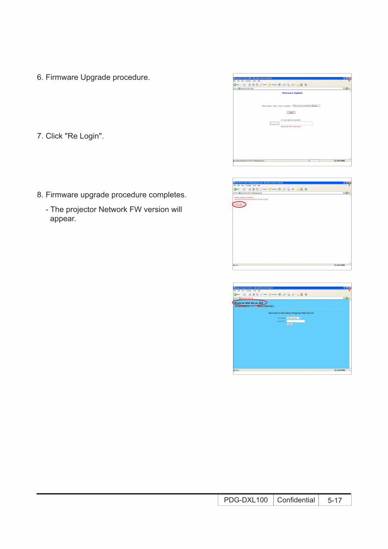
6. Firmware Upgrade procedure.
7. Click "Re Login".
8. Firmware upgrade procedure completes.
- The projector Network FW version will appear.

PDG-DXL100 Confidential 5-18
5-4 Waveform Download
- Plug in the power cord
- Hold on "Input" and "Enter" buttons, then press "Power" button.
- After several seconds, the Temp LED and Lamp LED will light red, then loosen "Input" and "Enter" buttons.
- After 5 seconds, the Temp LED and Lamp LED will flash red.
- Waveform Download is completed.
Waveform Download
Input button
Enter button
Section 4: Lamp Driver Waveform Download

PDG-DXL100 Confidential �
Note: This chapter is only designed to show the exploded image of the projector. For updated part numbers, please refer to RSPL report.
10
9
8
7
6
5
4
3
2
1
12
11
Appendix A (Exploded Image)
D.C. PDG-DXL100
PDG-DXL100 Confidential ��
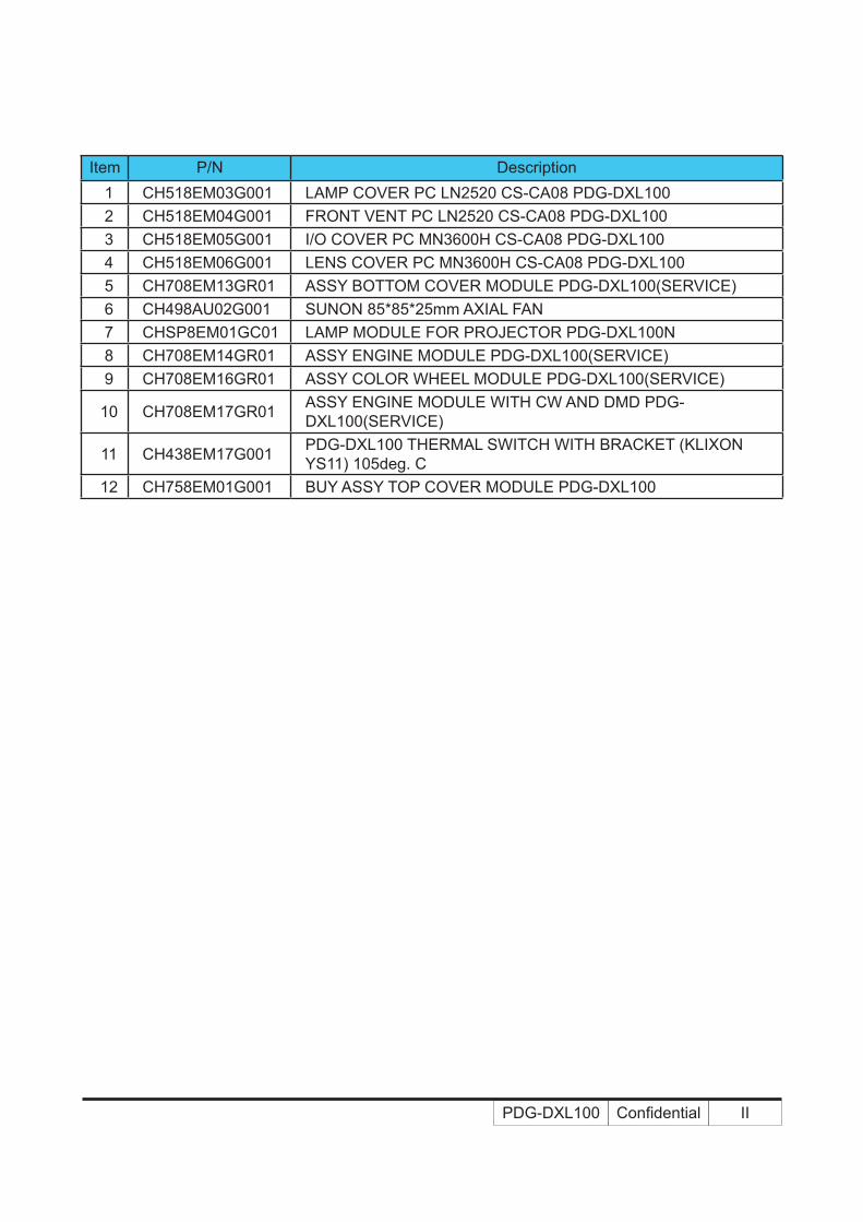
Item P/N Description1 CH518EM03G001 LAMP COVER PC LN2520 CS-CA08 PDG-DXL1002 CH518EM04G001 FRONT VENT PC LN2520 CS-CA08 PDG-DXL1003 CH518EM05G001 �/O COVER PC MN3600H CS-CA08 PDG-DXL1004 CH518EM06G001 LENS COVER PC MN3600H CS-CA08 PDG-DXL1005 CH708EM13GR01 ASSY BOTTOM COVER MODULE PDG-DXL100(SERV�CE)6 CH498AU02G001 SUNON 85*85*25mm AXIAL FAN7 CHSP8EM01GC01 LAMP MODULE FOR PROJECTOR PDG-DXL100N8 CH708EM14GR01 ASSY ENG�NE MODULE PDG-DXL100(SERV�CE)9 CH708EM16GR01 ASSY COLOR WHEEL MODULE PDG-DXL100(SERV�CE)
10 CH708EM17GR01 ASSY ENG�NE MODULE W�TH CW AND DMD PDG-DXL100(SERV�CE)
11 CH438EM17G001 PDG-DXL100 THERMAL SW�TCH W�TH BRACKET (KL�XON YS11) 105deg. C
12 CH758EM01G001 BUY ASSY TOP COVER MODULE PDG-DXL100

PDG-DXL100 Confidential ���
Item P/N Description1 CH498EM02G001 SUNON 45x20 BLOWER, F TYPE2 CH758AA04G001 BUY ASSY �NTERLOCK SW�TCH 1409X3 CH758EM01GP03 ASSY MATR�TEK CT-320 LVPS FOR PDG-DXL100(RELAY TYPE)4 CH498EM01G002 SPEAKER 8W 8-OHM W�TH GND W�RE PDG-DWL1005 CH758EL01G001 PHILIPS Euc 225 dW/C31(225W) for PDG-DWL100
2 5
4
3
21
ASSY BOTTOM MODULE

PDG-DXL100 Confidential �V
Item P/N Description1 CH5289601G041 ADJUST REAR FOOT RUBBER PDG-DXL1002 CH5289601G003 ADJUST FOOT RUBBER 65 DEGREE PD523PD
2
1
ASSY BOTTOM COVER MODULE
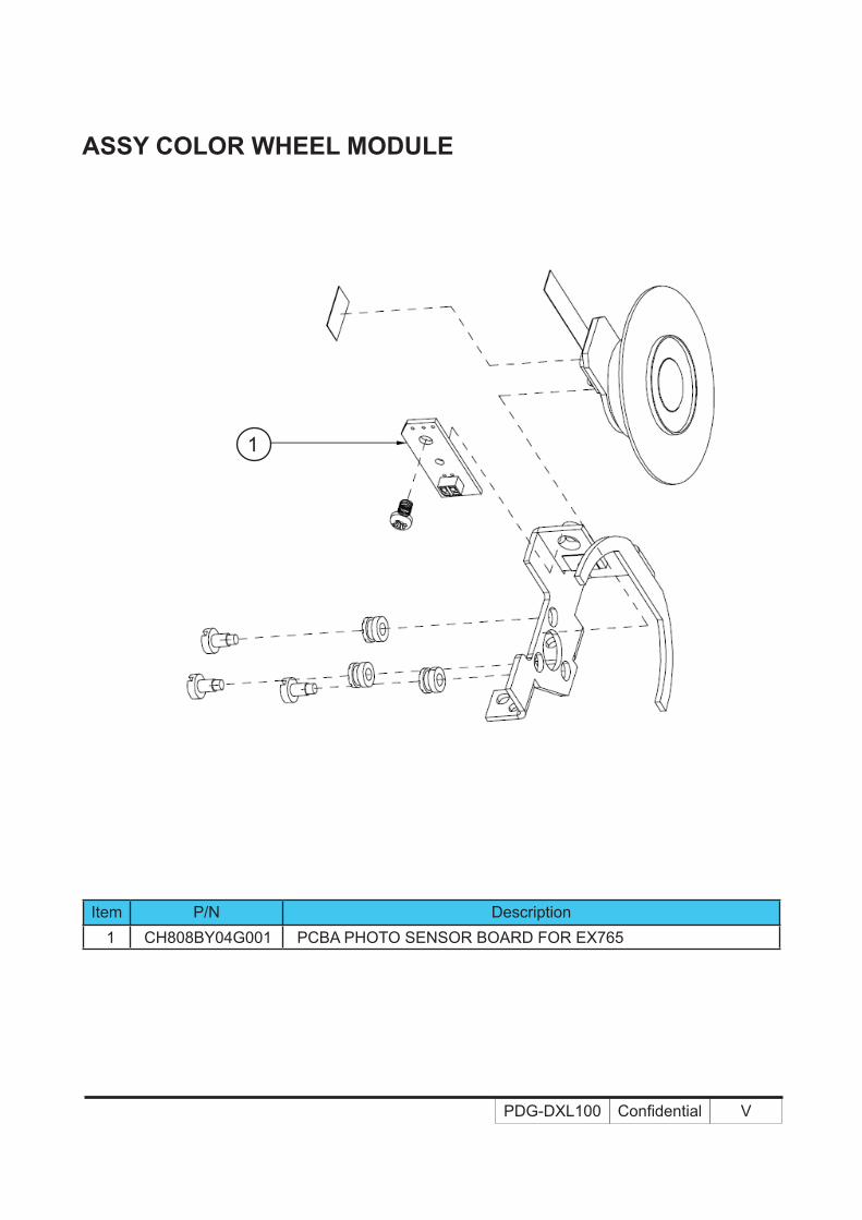
PDG-DXL100 Confidential V
Item P/N Description1 CH808BY04G001 PCBA PHOTO SENSOR BOARD FOR EX765
ASSY COLOR WHEEL MODULE
1

PDG-DXL100 Confidential V�
Item P/N Description
1 CH4889B01G002 DMD 1024X768 PIXEL .55” XGA 2xLVDS SUPER VALUE Type-X VERSION 2 “TI”
2 CH808EL02G001 PCBA DMD BOARD FOR PDG-DWL100
ASSY ENGINE MODULE
2
1

PDG-DXL100 Confidential V��
Item P/N Description1 CH758EM02G001 BUY ASSY KEYPAD MODULE PDG-DXL1002 CH4283C06G001 CABLE FFC 16P P=0.5 200mm KAYPAD TO M/B EP9103 CH808EM03G001 PCBA Keypad BD FOR SANYO PDG-DXL100 XGA_ST
ASSY TOP COVER MODULE
1
3
2

PDG-DXL100 Confidential V���
Item P/N Description1 CH808EM07G001 PCBA LAN MODULE BOARD FOR Sanyo PDG-DXL1002 CH808EM01G001 PCBA MAIN BD FOR SANYO PDG-DXL100 XGA_ST
ASSY MB MODULE
1
22
1

PDG-DXL100 Confidential �X
ASSY PACKING DRAWING
Item P/N Description1 CH558EM01G001 CARTON AB FLUTE 18KG PDG-DXL1002 CH558EM02G001 R�GHT PART�T�ON PDG-DXL1003 CH558EM03G001 LEFT PART�T�ON PDG-DXL1004 CH568EM01G001 PACK�NG R�GHT EPE PDG-DXL1005 CH568EM02G001 PACK�NG LEFT EPE PDG-DXL1006 CH458EL01G001 REMOTE CONTROLLER FOR PDG-DWL100
7 CH4200105G011 CABLE POWER CORD 1.8M SP-305A/IS-14 US DIS-WARNING LABEL
CH4200120G011 CABLE POWER CORD 1.8M SP-023/IS-14 EUROPE DIS-WARN-�NG LABEL
CH4200110G011 CABLE POWER CORD 1.8M SP-60/IS-14 UK DIS-WARNING LABEL
8 CH568EM03G001 PACK�NG EPE BAG 420*500MM DXL1009 CH368EM01G001 USER’S GU�DE MULT�L�NGUAL SANYO DXL100
10 CH3589504G001 LABEL CARTON 108*92 BLANK
63
7
9
58
42 110

PDG-DWL100 Confidential �
Appendix B I. Serial Number System Definition
Serial Number Format for Projector
5 9 6 01002
1 2 3
1 : 9 = Last number of the manufacture year (ex:2009 = 9)
2 : 6 = Month (ex:6 = June)
3 : 01002 = Production number (5 digits), It starts from
“01001” ~“99999”
EX: 59601002
This label "59601002" represents the serial number for PDG-DWL100. It is produced on June of 2009. Its serial code is 01002.

PDG-DWL100 Confidential ��
II. PCBA Code Definition
PCBA Code for Projector
A B XXXXXXXXXXX C XXX EEEE
1 2 3 4 5 6
1 : ID
2 : Vendor Code
3 : P/N
4 : Revision
5 : Date Code
6 : S/N

PRODUCT CODE1 682 347 81
SANYO Electric Co., Ltd.Printed In Japan