Embed Size (px)
Citation preview
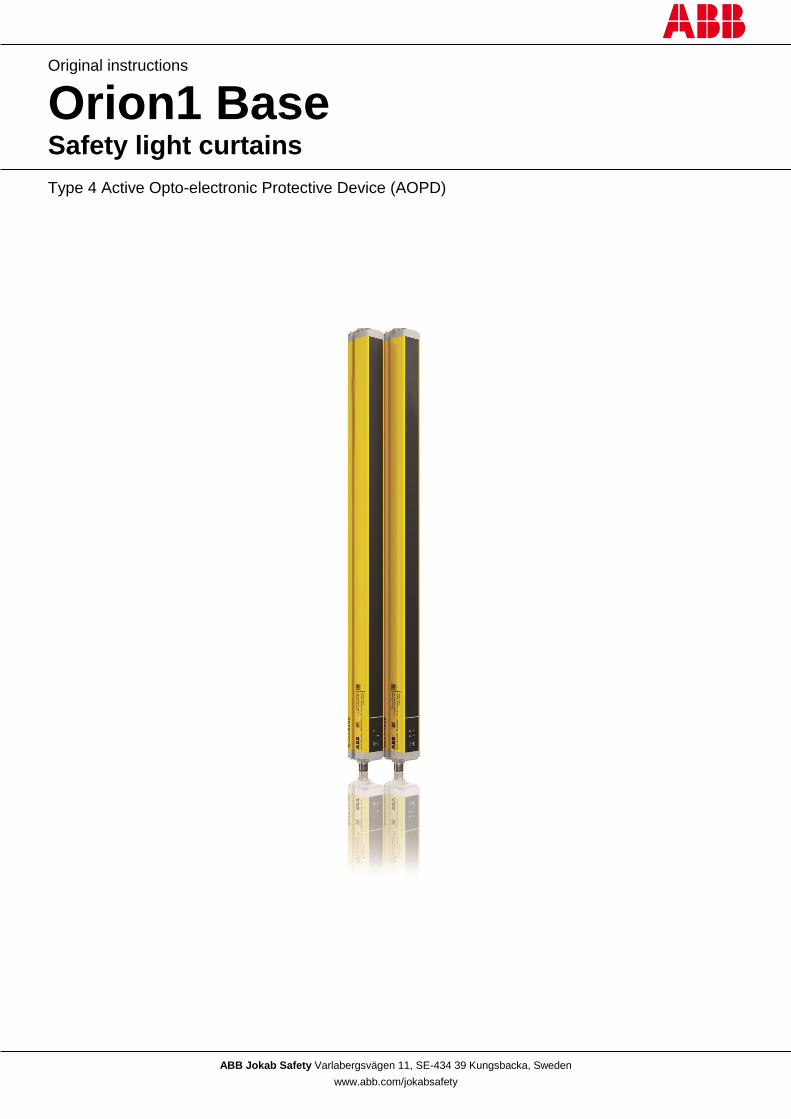
ABB Jokab Safety Varlabergsvägen 11, SE-434 39 Kungsbacka, Sweden
www.abb.com/jokabsafety
Original instructions
Orion1 Base Safety light curtains
Type 4 Active Opto-electronic Protective Device (AOPD)

2TLC172287M0201 Rev B 2 www.abb.com/jokabsafety
2015-09-17
Read and understand this document
Please read and understand this document before using the products. Please consult your ABB JOKAB SAFETY
representative if you have any questions or comments.
WARRANTY
ABB JOKAB SAFETY’s exclusive warranty is that the products are free from defects in materials and workmanship for a period of one year (or other period if specified) from date of sale by ABB JOKAB SAFETY.
ABB JOKAB SAFETY MAKES NO WARRANTY OR REPRESENTATION, EXPRESSED OR IMPLIED, REGARDING NON-INFRINGEMENT, MERCHANTABILITY, OR FITNESS FOR PARTICULAR PURPOSE OF THE PRODUCTS, ANY BUYER OR USER ACKNOWLEDGES THAT THE BUYER OR USER ALONE HAS DETERMINED THAT THE PRODUCTS WILL SUITABLY MEET THE REQUIREMENTS OR THEIR INTENDED USE. ABB JOKAB SAFETY DISCLAIMS ALL OTHER WARRANTIES, EXPRESSED OR IMPLIED.
LIMITATIONS OF LIABILITY
ABB JOKAB SAFETY SHALL NOT BE RESPONSIBLE FOR SPECIAL, INDIRECT, OR CONSEQUENTIAL DAMAGES, LOSS OF PROFITS OR COMMERCIAL LOSS IN ANY WAY CONNECTED WITH THE PRODUCTS, WHETHER SUCH CLAIM IS BASED ON CONTRACT, WARRANTY, NEGLIGENCE, OR STRICT LIABILITY.
In no event shall responsibility of ABB JOKAB SAFETY for any act exceed the individual price of the product on which liability asserted.
IN NO EVENT SHALL ABB JOKAB SAFETY BE RESPONSIBLE FOR WARRANTY, REPAIR, OR OTHER CLAIMS REGARDING THE PRODUCTS UNLESS ABB JOKAB SAFETY’S ANALYSIS CONFIRMS THAT THE PRODUCTS WERE PROPERLY HANDLED, STORED, INSTALLED, AND MAINTAINED AND NOT SUBJECT TO ABUSE, MISUSE, OR INAPPROPRIATE MODIFICATION OR REPAIR.
SUITABILITY FOR USE
ABB JOKAB SAFETY shall not be responsible for conformity with any standards, codes, or regulations that apply to the combination of products in the customer’s application or use of the product. At the customer’s request, ABB JOKAB SAFETY will provide applicable third party certification documents identifying ratings and limitations of use that apply to the products. This information by itself is not sufficient for a complete determination of the suitability of the products in combination with the end product, machine, system, or other application or use.
The following are some examples of applications for which particular attention must be given. This is not intended to be an exhaustive list of all possible uses of the products, nor is it intended to imply that the uses listed may be suitable for the products:
Outdoor use, uses involving potential chemical contamination or electrical interference, or conditions or uses not described in this document.
Nuclear energy control systems, combustion systems, railroad systems, aviation systems, medical equipment, amusement machines, vehicles, and installations subject to separate industry or government regulations.
Systems, machines, and equipment that could present a risk to life or property.
Please know and observe all prohibitions of use applicable to the products.
NEVER USE THE PRODUCTS FOR AN APPLICATION INVOLVING SERIOUS RISK TO LIFE OR PROPERTY WITHOUT ENSURING THAT THE SYSTEM AS A WHOLE HAS BEEN DESIGNED TO ADDRESS THE RISKS, AND THAT THE ABB JOKAB SAFETY PRODUCT IS PROPERLY RATED AND INSTALLED FOR THE INTENDED USE WITHIN THE OVERALL EQUIPMENT OR SYSTEM.
PERFORMANCE DATA
While every effort has been taken to ensure the accuracy of the information contained in this manual ABB JOKAB SAFETY cannot accept responsibility for errors or omissions and reserves the right to make changes and improvements without notice. Performance data given in this document is provided as a guide for the user in determining suitability and does not constitute a warranty. It may represent the result of ABB JOKAB SAFETY’s test conditions, and the users must correlate it to actual application requirements. Actual performance is subject to the ABB JOKAB SAFETY Warranty and Limitations of Liability.
2TLC172287M0201 Rev B 3 www.abb.com/jokabsafety
2015-09-17
Table of Contents
1 Introduction ......................................................................................................................................... 5
1.1 Scope ................................................................................................................................................................. 5
1.2 Audience ............................................................................................................................................................ 5
1.3 Prerequisites ...................................................................................................................................................... 5
1.4 Abbreviations ..................................................................................................................................................... 5
1.5 Special notes ..................................................................................................................................................... 5
2 Overview .............................................................................................................................................. 6
2.1 General description ............................................................................................................................................ 6
2.2 Resolution .......................................................................................................................................................... 7
2.3 Protected height ................................................................................................................................................. 8
2.4 Minimum installation distance ............................................................................................................................ 9
2.4.1 Vertically assembled AOPD ....................................................................................................................... 9
2.4.2 Horizontally assembled AOPD ................................................................................................................. 10
2.4.3 Angled assembled AOPD ........................................................................................................................ 10
2.4.4 Practical examples ................................................................................................................................... 10
2.5 Safety information ............................................................................................................................................ 11
3 Installation ......................................................................................................................................... 12
3.1 Precautions to observe for the choice and installation of the AOPD ............................................................... 12
3.2 General information on positioning the AOPD ................................................................................................. 12
3.2.1 Minimum installation distance .................................................................................................................. 13
3.2.2 Minimum distance to reflecting surfaces .................................................................................................. 13
3.2.3 Minimum distance between adjacent devices ......................................................................................... 15
3.2.4 Installation of several adjacent AOPDs.................................................................................................... 16
3.2.5 Transmitter and receiver orientation ........................................................................................................ 17
3.2.6 Use of deviating mirrors ........................................................................................................................... 17
3.3 Checks after first installation ............................................................................................................................ 18
4 Mechanical mounting ........................................................................................................................ 19
4.1 Mounting with angled fixing brackets ............................................................................................................... 19
5 Electrical connections....................................................................................................................... 20
5.1 Transmitter (TX) ............................................................................................................................................... 20
5.2 Receiver (RX) .................................................................................................................................................. 20
5.3 Important notes on connections ...................................................................................................................... 21
5.4 Connection examples ...................................................................................................................................... 22
6 Alignment procedure ........................................................................................................................ 26
6.1 Alignment mode ............................................................................................................................................... 27
6.2 Correct alignment procedure ........................................................................................................................... 27
7 Functions ........................................................................................................................................... 29
7.1 Reset function .................................................................................................................................................. 29
7.2 Test function .................................................................................................................................................... 30
2TLC172287M0201 Rev B 4 www.abb.com/jokabsafety
2015-09-17
7.3 Acknowledge function ...................................................................................................................................... 30
7.4 EDM function ................................................................................................................................................... 31
8 Diagnostic functions ......................................................................................................................... 32
8.1 Visualisation of the status of the AOPD ........................................................................................................... 32
8.2 Diagnostic messages ....................................................................................................................................... 32
8.2.1 Transmitter ............................................................................................................................................... 32
8.2.2 Receiver ................................................................................................................................................... 33
9 Periodical checks .............................................................................................................................. 34
10 Device maintenance .......................................................................................................................... 35
11 Technical data ................................................................................................................................... 36
12 Model overview .................................................................................................................................. 38
13 Dimensions ........................................................................................................................................ 39
13.1 Profiles ............................................................................................................................................................. 39
13.2 Angled fixing bracket ....................................................................................................................................... 40
13.3 Fixing bracket with profile ................................................................................................................................ 40
14 EC Declaration of conformity ........................................................................................................... 41
2TLC172287M0201 Rev B 5 www.abb.com/jokabsafety
2015-09-17
1 Introduction
1.1 Scope
The purpose of these instructions is to describe the Orion1 Base light curtains and to provide the necessary
information required for selection, installation and operation of the safety devices.
1.2 Audience
This document is intended for authorized installation personnel.
1.3 Prerequisites
It is assumed that the reader of this document has knowledge of the following:
Basic knowledge of ABB Jokab Safety products.
Knowledge of machine safety.
1.4 Abbreviations
ACM: Advanced Configuration Mode
AOPD: Active Opto-electronic Protective Device
BCM: Basic Configuration Mode
EDM: External Device Monitoring
MPCE: Machine Primary Control Element
OSSD: Output Signal Switching Device (switching output)
RX: Receiver
TX: Transmitter
1.5 Special notes
Pay attention to the following special notes in the document:
Warning!
Danger of severe personal injury!
An instruction or procedure which, if not carried out correctly, may result in injury to the operator or other personnel.
Caution! Danger of damage to the equipment!
An instruction or procedure which, if not carried out correctly, may damage the equipment.
NB: Notes are used to provide important or explanatory information.
2TLC172287M0201 Rev B 6 www.abb.com/jokabsafety
2015-09-17
2 Overview
2.1 General description
The Orion1 Base light curtains are Active Opto-electronic Protective Devices (AOPDs) that are used to protect
working areas that, in presence of machines, robots, and automatic systems in general, can become hazardous for
operators that can get in touch, even accidentally, with moving parts.
The Orion1 Base light curtains are Type 4 intrinsic safety systems used as accident-prevention protection devices and
are manufactured in accordance with the international standards in force for safety, in particular:
EN 61496-1:2013 Safety of machinery – Electro-sensitive protective equipment – Part 1: General requirements and tests
IEC 61496-2:2013 Safety of machinery – Electro-sensitive protective equipment – Part 2: Particular requirements for equipment using active opto-electronic protective devices (AOPDs)
EN ISO 13849-1:2008 Safety of machinery – Safety-related parts of control systems – Part 1: General principles for design
EN 61508-1:2010 Functional safety of electrical/electronic/programmable electronic safety-related systems – Part 1: General requirements
EN 61508-2:2010 Functional safety of electrical/electronic/programmable electronic safety-related systems – Part 2: Requirements for electrical/electronic/programmable electronic safety-related systems
EN 61508-3:2010 Functional safety of electrical/electronic/programmable electronic safety-related systems – Part 3: Software requirements
EN 61508-4:2010 Functional safety of electrical/electronic/programmable electronic safety-related systems – Part 4: Definitions and abbreviations
EN 62061:2005/A1:2013 Safety of machinery – Functional safety of safety-related electrical, electronic and programmable electronic control systems
The device, consisting of one transmitter and one receiver housed inside strong aluminium profiles, generates infrared
beams and detects any opaque object interrupting a beam. The 2 units are composed by one or several transmitting
and receiving modules.
The transmitter and the receiver are equipped with the command and control functions. The receiver checks the
control operations and safety actions.
The synchronisation between the transmitter and the receiver takes place optically, i.e. no electrical connection
between the two units is required.
The microprocessors guarantee the check and the management of the beams that are sent and received and the
microprocessors inform the operator about the general conditions of the AOPD, including errors, via LEDs (see
paragraph 8 – “Diagnostic functions”).
The connections are made through a M12 connector located in the lower side of the profile.
During installation, a display facilitates the alignment of both units (see paragraph 6 – “Alignment procedure”).
As soon as an object, a limb or the operator’s body accidentally interrupts one or several of the infrared beams sent by
the transmitter, the OSSD outputs switch off and block the Machine Primary Control Element, MPCE (if correctly
connected to the OSSD outputs).
2TLC172287M0201 Rev B 7 www.abb.com/jokabsafety
2015-09-17
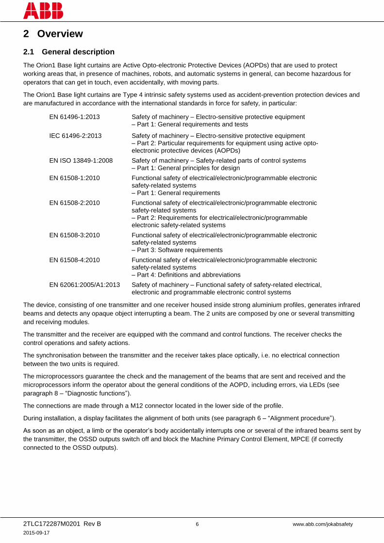
2.2 Resolution
The resolution of the AOPD is the minimum dimension that an opaque object must have in order to interrupt at least
one of the beams that constitute the detection zone.
Which resolution to choose depends on the part of the body to be protected:
R = 14mm Finger protection
R = 30 mm Hand protection
The resolution R is calculated using the following formula:
R = I + d
where:
I Distance between the centers of two adjacent optics.
d Diameter of the lens.
Figure 1 – Resolution
Therefore, the resolution depends only on the geometrical characteristics of the lenses, diameter and distance
between centers, and is independent of any environmental and operating conditions of the AOPD.
See paragraph 12 – “Model overview” for the resolution of each model.
Type 4
Type 4
2TLC172287M0201 Rev B 8 www.abb.com/jokabsafety
2015-09-17
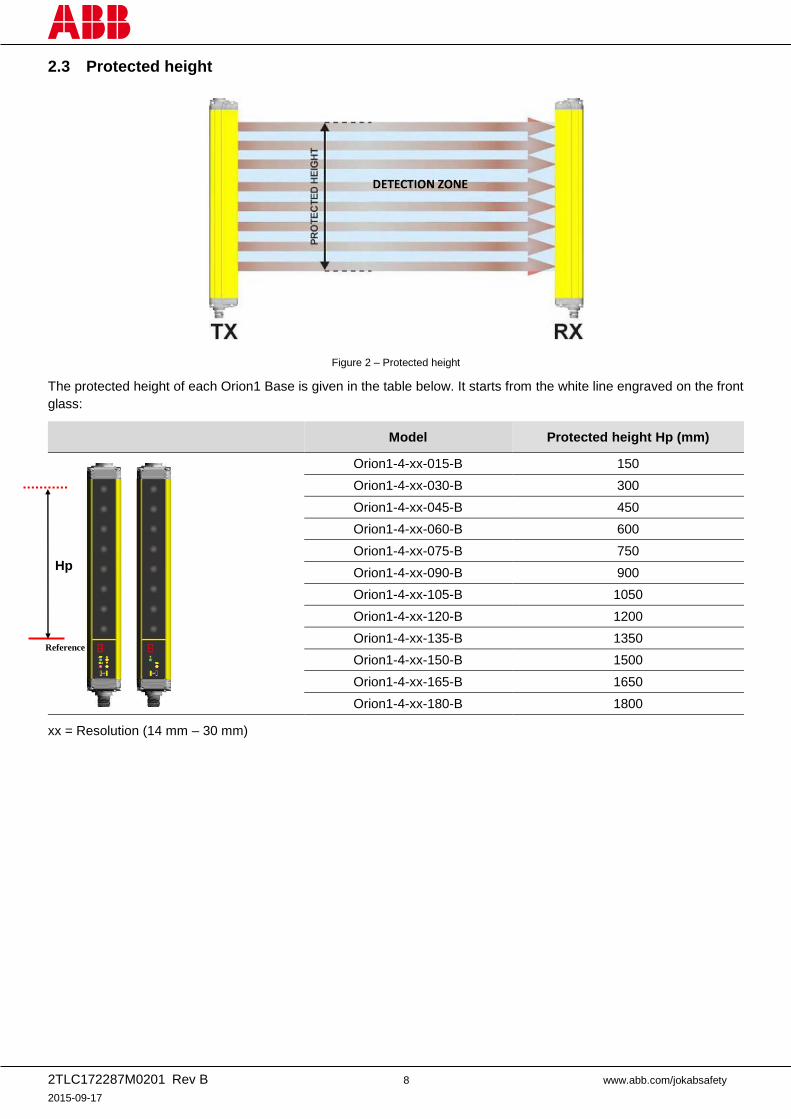
2.3 Protected height
Figure 2 – Protected height
The protected height of each Orion1 Base is given in the table below. It starts from the white line engraved on the front
glass:
Model Protected height Hp (mm)
Orion1-4-xx-015-B 150
Orion1-4-xx-030-B 300
Orion1-4-xx-045-B 450
Orion1-4-xx-060-B 600
Orion1-4-xx-075-B 750
Orion1-4-xx-090-B 900
Orion1-4-xx-105-B 1050
Orion1-4-xx-120-B 1200
Orion1-4-xx-135-B 1350
Orion1-4-xx-150-B 1500
Orion1-4-xx-165-B 1650
Orion1-4-xx-180-B 1800
xx = Resolution (14 mm – 30 mm)
Hp
Reference
2TLC172287M0201 Rev B 9 www.abb.com/jokabsafety
2015-09-17
2.4 Minimum installation distance
Warning! The information given in this chapter shall be considered as an overview. For correct positioning, please
refer to the latest version of the complete standard EN ISO 13855 ”Safety of machinery – Positioning of safeguards
with respect to the approach speeds of parts of the human body”.
The safety device must be positioned at a distance that prevents a person or part of a person to reach the hazard
zone before the hazardous motion of the machine has been stopped by the AOPD.
According to EN ISO 13855:2010, the minimum distance to the hazard zone is calculated using:
S = (K × T) + C
S Minimum distance (mm) between safeguard and hazard zone.
K Approach speed of body parts towards the hazard zone (mm/s). See below for values.
T Overall system stopping performance (s) with T = T1 + T2, where:
T1 = response time of the AOPD (s).
T2 = stopping time of the machine, including the response time of the safety control system (s).
C Intrusion distance (mm). C depends on the resolution d and the position of the detection zone. See below.
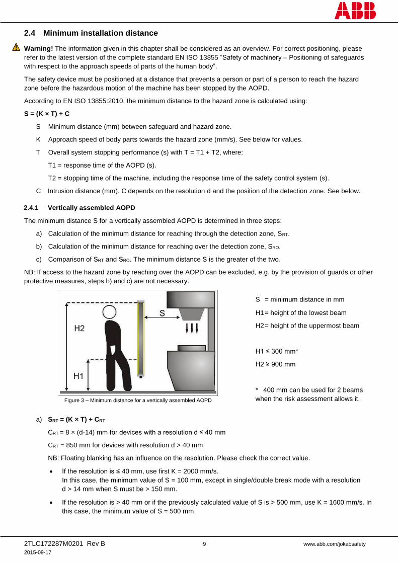
2.4.1 Vertically assembled AOPD
The minimum distance S for a vertically assembled AOPD is determined in three steps:
a) Calculation of the minimum distance for reaching through the detection zone, SRT.
b) Calculation of the minimum distance for reaching over the detection zone, SRO.
c) Comparison of SRT and SRO. The minimum distance S is the greater of the two.
NB: If access to the hazard zone by reaching over the AOPD can be excluded, e.g. by the provision of guards or other
protective measures, steps b) and c) are not necessary.
Figure 3 – Minimum distance for a vertically assembled AOPD
S = minimum distance in mm
H1 = height of the lowest beam
H2 = height of the uppermost beam
H1 ≤ 300 mm*
H2 ≥ 900 mm
* 400 mm can be used for 2 beams
when the risk assessment allows it.
a) SRT = (K × T) + CRT
CRT = 8 × (d-14) mm for devices with a resolution d ≤ 40 mm
CRT = 850 mm for devices with resolution d > 40 mm
NB: Floating blanking has an influence on the resolution. Please check the correct value.
If the resolution is ≤ 40 mm, use first K = 2000 mm/s.
In this case, the minimum value of S = 100 mm, except in single/double break mode with a resolution
d > 14 mm when S must be > 150 mm.
If the resolution is > 40 mm or if the previously calculated value of S is > 500 mm, use K = 1600 mm/s. In
this case, the minimum value of S = 500 mm.
2TLC172287M0201 Rev B 10 www.abb.com/jokabsafety
2015-09-17
b) SRO = (K × T) + CRO
K and T according to a).
CRO = Intrusion distance when reaching over the AOPD towards the hazard zone prior to the actuation of the
AOPD. This value depends on the height of the hazard zone and the height of the uppermost beam,
see EN ISO 13855:2010.
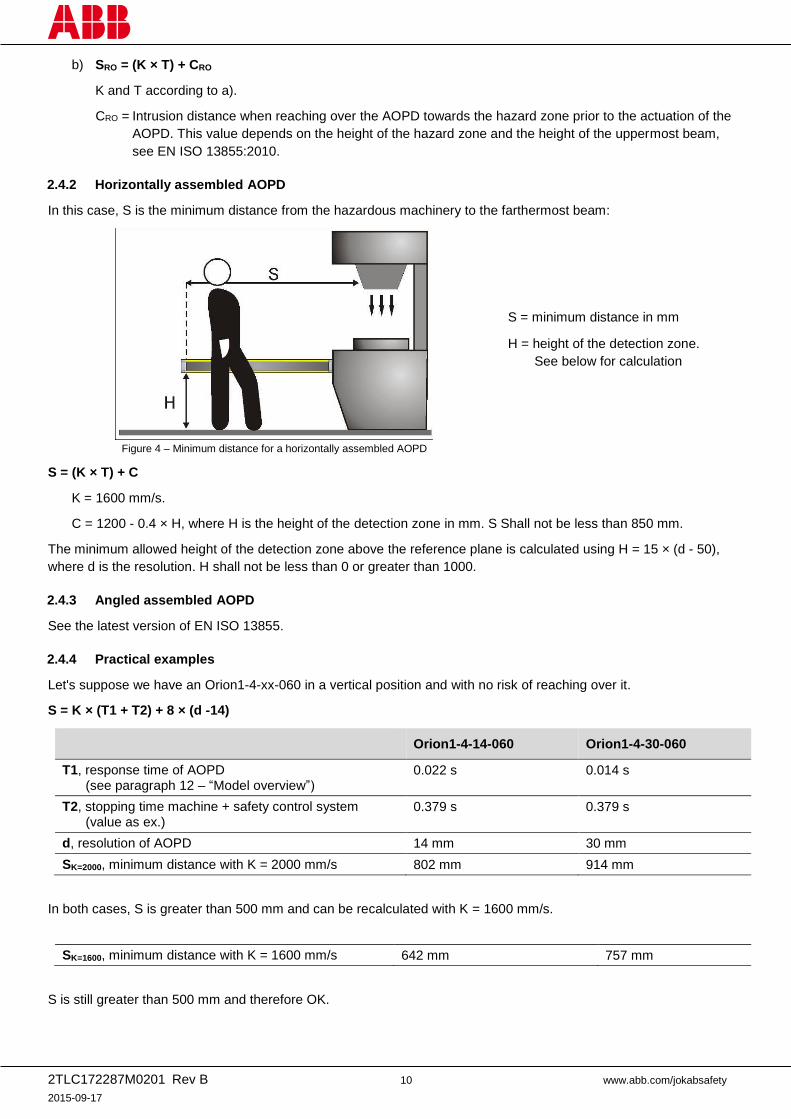
2.4.2 Horizontally assembled AOPD
In this case, S is the minimum distance from the hazardous machinery to the farthermost beam:
Figure 4 – Minimum distance for a horizontally assembled AOPD
S = minimum distance in mm
H = height of the detection zone.
See below for calculation
S = (K × T) + C
K = 1600 mm/s.
C = 1200 - 0.4 × H, where H is the height of the detection zone in mm. S Shall not be less than 850 mm.
The minimum allowed height of the detection zone above the reference plane is calculated using H = 15 × (d - 50),
where d is the resolution. H shall not be less than 0 or greater than 1000.
2.4.3 Angled assembled AOPD
See the latest version of EN ISO 13855.
2.4.4 Practical examples
Let's suppose we have an Orion1-4-xx-060 in a vertical position and with no risk of reaching over it.
S = K × (T1 + T2) + 8 × (d -14)
Orion1-4-14-060 Orion1-4-30-060
T1, response time of AOPD (see paragraph 12 – “Model overview”)
0.022 s 0.014 s
T2, stopping time machine + safety control system (value as ex.)
0.379 s 0.379 s
d, resolution of AOPD 14 mm 30 mm
SK=2000, minimum distance with K = 2000 mm/s 802 mm 914 mm
In both cases, S is greater than 500 mm and can be recalculated with K = 1600 mm/s.
SK=1600, minimum distance with K = 1600 mm/s 642 mm 757 mm
S is still greater than 500 mm and therefore OK.
2TLC172287M0201 Rev B 11 www.abb.com/jokabsafety
2015-09-17
2.5 Safety information
Warning!
For a correct and safe use of the Orion1 Base light curtains, the following points must be observed:
The stopping system of the machine must be electrically controlled.
This control system must be able to stop the hazardous movement of the machine within the total machine
stopping time T as per paragraph 2.4 – “Minimum installation distance”, and during all working cycle phases.
Mounting and connection of the AOPD must be carried out by qualified personnel only, according to the
indications included in the special sections (see paragraphs 3; 4; 5; 6) and in the applicable standards.
The AOPD must be securely placed in a particular position so that access to the hazard zone is not possible
without the interruption of the beams (see paragraph 3 -”Installation”).
The personnel operating in the hazard zone must be well trained and must have adequate knowledge of all
the operating procedures of the AOPD.
The TEST button must be located outside the hazard zone because the operator must check the hazard zone
during all the test operations.
The ACKNOWLEDGE/RESET button must be located outside the hazard zone because the operator must
check the hazard zone during all acknowledge/reset operations. It must be impossible to reach the button
from the hazard zone.
If the external device monitoring (EDM) function is used, it must be activated by connecting a specific wire to
the device, see paragraph 5 – “Electrical connections”.
Please carefully read the instructions for the correct functioning before powering the AOPD.
2TLC172287M0201 Rev B 12 www.abb.com/jokabsafety
2015-09-17
3 Installation
3.1 Precautions to observe for the choice and installation of the AOPD
The outputs (OSSD) of the AOPD must be used as machine stopping devices and not as command devices.
The machine must have its own Start command.
The dimension of the smallest object to be detected must be larger than the resolution of the AOPD.
The AOPD must be installed in a room complying with the technical characteristics indicated in
paragraph 11 – “Technical data”.
Do not place the AOPD near strong and/or flashing light sources or similar devices.
Strong electromagnetic interferences can jeopardize the function of the AOPD. Please contact your
ABB Jokab Safety representative for advice.
The operating distance of the device can be reduced in presence of smog, fog or airborne dust.
A sudden change in environment temperature, with very low minimum peaks, can generate a small
condensation layer on the lenses and jeopardize the function.
3.2 General information on positioning the AOPD
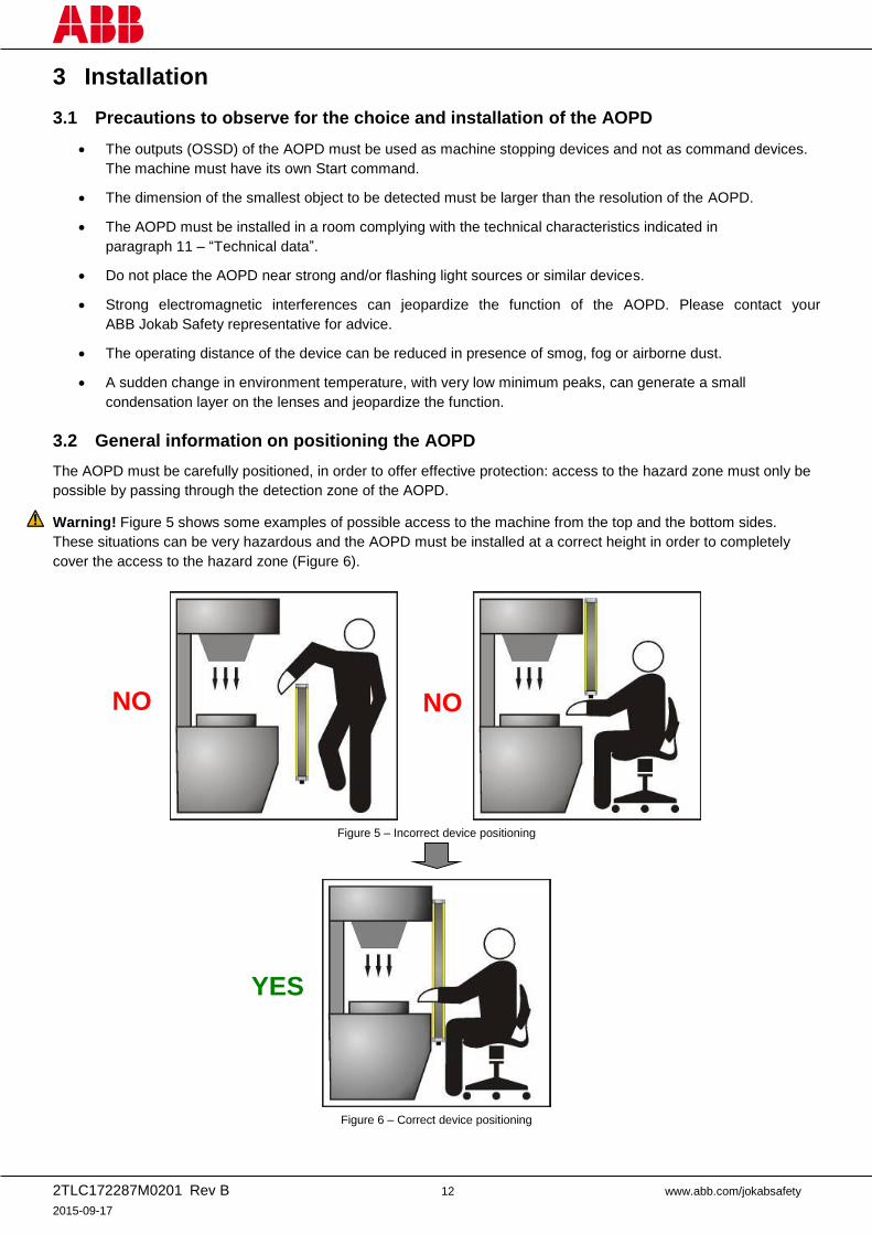
The AOPD must be carefully positioned, in order to offer effective protection: access to the hazard zone must only be
possible by passing through the detection zone of the AOPD.
Warning! Figure 5 shows some examples of possible access to the machine from the top and the bottom sides.
These situations can be very hazardous and the AOPD must be installed at a correct height in order to completely
cover the access to the hazard zone (Figure 6).
Figure 5 – Incorrect device positioning
Figure 6 – Correct device positioning
YES
NO NO
2TLC172287M0201 Rev B 13 www.abb.com/jokabsafety
2015-09-17
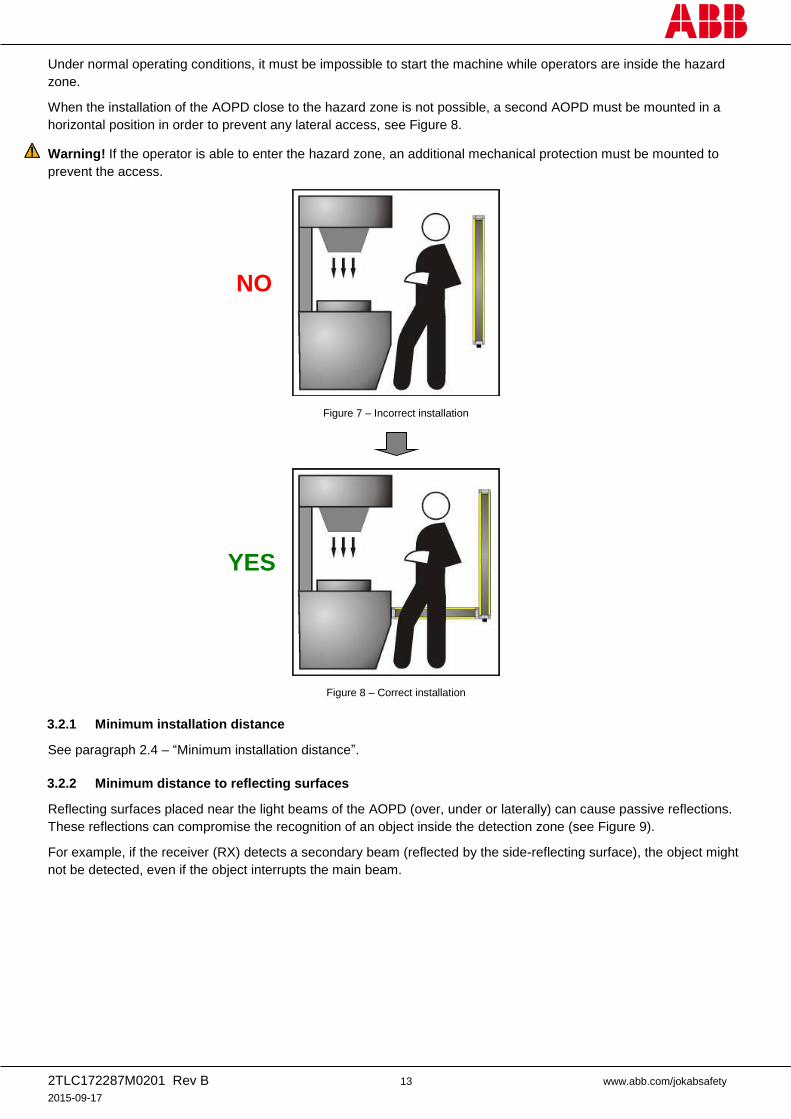
Under normal operating conditions, it must be impossible to start the machine while operators are inside the hazard
zone.
When the installation of the AOPD close to the hazard zone is not possible, a second AOPD must be mounted in a
horizontal position in order to prevent any lateral access, see Figure 8.
Warning! If the operator is able to enter the hazard zone, an additional mechanical protection must be mounted to
prevent the access.
Figure 7 – Incorrect installation
Figure 8 – Correct installation
3.2.1 Minimum installation distance
See paragraph 2.4 – “Minimum installation distance”.
3.2.2 Minimum distance to reflecting surfaces
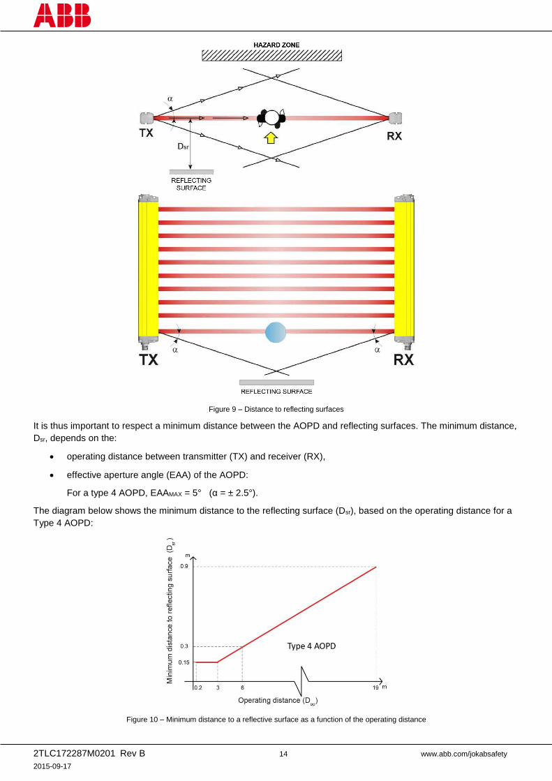
Reflecting surfaces placed near the light beams of the AOPD (over, under or laterally) can cause passive reflections.
These reflections can compromise the recognition of an object inside the detection zone (see Figure 9).
For example, if the receiver (RX) detects a secondary beam (reflected by the side-reflecting surface), the object might
not be detected, even if the object interrupts the main beam.
NO
YES
2TLC172287M0201 Rev B 14 www.abb.com/jokabsafety
2015-09-17
Figure 9 – Distance to reflecting surfaces
It is thus important to respect a minimum distance between the AOPD and reflecting surfaces. The minimum distance,
Dsr, depends on the:
operating distance between transmitter (TX) and receiver (RX),
effective aperture angle (EAA) of the AOPD:
For a type 4 AOPD, EAAMAX = 5° (α = ± 2.5°).
The diagram below shows the minimum distance to the reflecting surface (Dsr), based on the operating distance for a
Type 4 AOPD:
Figure 10 – Minimum distance to a reflective surface as a function of the operating distance
2TLC172287M0201 Rev B 15 www.abb.com/jokabsafety
2015-09-17
The formula to get Dsr for a Type 4 AOPD is the following:
Dsr (m) = 0.15 for operating distance < 3 m
Dsr (m) = 0.5 × operating distance (m) × tan (2) for operating distance 3 m
Warning! If the reflecting surface is the floor, the calculated Dsr can be less than the correct height to the floor that
still must be respected.
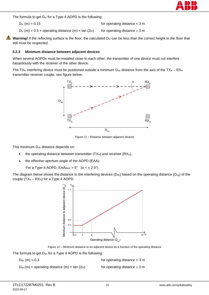
3.2.3 Minimum distance between adjacent devices
When several AOPDs must be installed close to each other, the transmitter of one device must not interfere
hazardously with the receiver of the other device.
The TXB interfering device must be positioned outside a minimum Ddo distance from the axis of the TXA – RXA
transmitter-receiver couple, see figure below.
Figure 11 – Distance between adjacent devices
This minimum Ddo distance depends on:
the operating distance between transmitter (TXA) and receiver (RXA),
the effective aperture angle of the AOPD (EAA):
For a Type 4 AOPD, EAAMAX = 5° (α = ± 2.5°).
The diagram below shows the distance to the interfering devices (Ddo) based on the operating distance (Dop) of the
couple (TXA – RXA) for a Type 4 AOPD.
Figure 12 – Minimum distance to an adjacent device as a function of the operating distance
The formula to get Ddo for a Type 4 AOPD is the following:
Ddo (m) = 0.3 for operating distance < 3 m
Ddo (m) = operating distance (m) × tan (2) for operating distance 3 m
2TLC172287M0201 Rev B 16 www.abb.com/jokabsafety
2015-09-17
Warning! Please note that TXA can interfere with RXB in the same way as TXB with RXA and, if the two pairs of AOPD
have different operating distances, the longest one should be used for the calculation of Ddo.
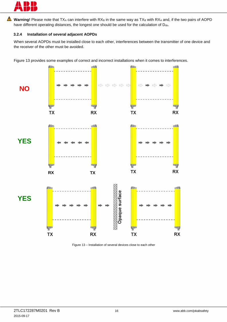
3.2.4 Installation of several adjacent AOPDs
When several AOPDs must be installed close to each other, interferences between the transmitter of one device and
the receiver of the other must be avoided.
Figure 13 provides some examples of correct and incorrect installations when it comes to interferences.
Figure 13 – Installation of several devices close to each other
NO
YES
RX TX
YES
2TLC172287M0201 Rev B 17 www.abb.com/jokabsafety
2015-09-17
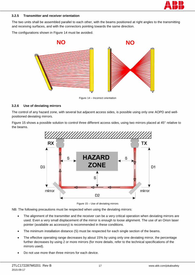
3.2.5 Transmitter and receiver orientation
The two units shall be assembled parallel to each other, with the beams positioned at right angles to the transmitting
and receiving surfaces, and with the connectors pointing towards the same direction.
The configurations shown in Figure 14 must be avoided.
Figure 14 – Incorrect orientation
3.2.6 Use of deviating mirrors
The control of any hazard zone, with several but adjacent access sides, is possible using only one AOPD and well-
positioned deviating mirrors.
Figure 15 shows a possible solution to control three different access sides, using two mirrors placed at 45° relative to
the beams.
Figure 15 – Use of deviating mirrors
NB: The following precautions must be respected when using the deviating mirrors:
The alignment of the transmitter and the receiver can be a very critical operation when deviating mirrors are
used. Even a very small displacement of the mirror is enough to loose alignment. The use of an Orion laser
pointer (available as accessory) is recommended in these conditions.
The minimum installation distance (S) must be respected for each single section of the beams.
The effective operating range decreases by about 15% by using only one deviating mirror, the percentage
further decreases by using 2 or more mirrors (for more details, refer to the technical specifications of the
mirrors used).
Do not use more than three mirrors for each device.
NO
NO
2TLC172287M0201 Rev B 18 www.abb.com/jokabsafety
2015-09-17
The presence of dust or dirt on the reflecting surface of the mirror causes a drastic reduction in the range.
The following table shows the operating distances relating to the number of mirrors used.
Number
of mirrors
Operating distance
(14 mm)
Operating distance
(30 mm)
1 5.1 m 16.5 m
2 4.3 m 13.7 m
3 3.7 m 11.6 m
3.3 Checks after first installation
The control operations to carry-out after the first installation and before machine start-up are listed hereinafter. The
controls must be carried-out by qualified personnel, either directly or under the strict supervision of the person in
charge of machinery safety.
Check that:
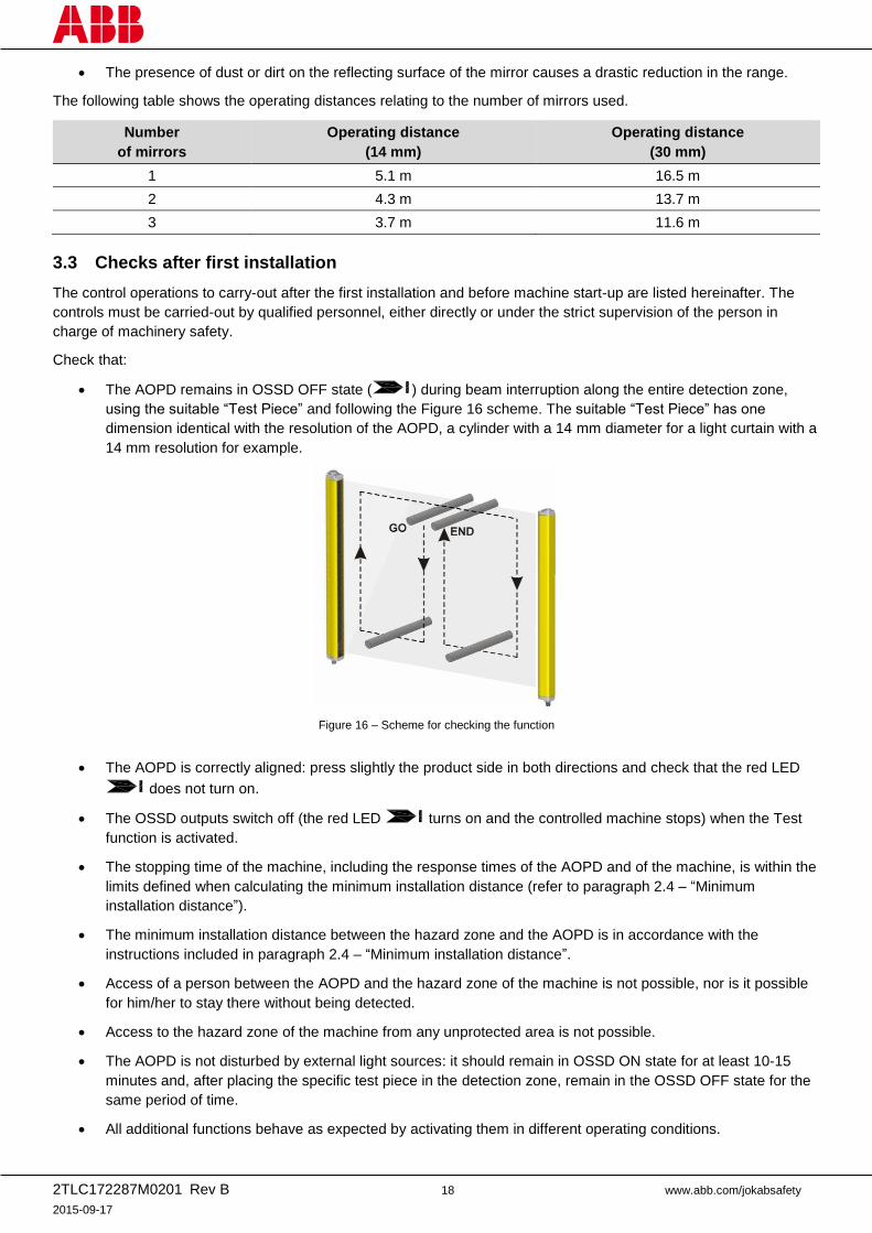
The AOPD remains in OSSD OFF state ( ) during beam interruption along the entire detection zone,
using the suitable “Test Piece” and following the Figure 16 scheme. The suitable “Test Piece” has one
dimension identical with the resolution of the AOPD, a cylinder with a 14 mm diameter for a light curtain with a
14 mm resolution for example.
Figure 16 – Scheme for checking the function
The AOPD is correctly aligned: press slightly the product side in both directions and check that the red LED
does not turn on.
The OSSD outputs switch off (the red LED turns on and the controlled machine stops) when the Test
function is activated.
The stopping time of the machine, including the response times of the AOPD and of the machine, is within the
limits defined when calculating the minimum installation distance (refer to paragraph 2.4 – “Minimum
installation distance”).
The minimum installation distance between the hazard zone and the AOPD is in accordance with the
instructions included in paragraph 2.4 – “Minimum installation distance”.
Access of a person between the AOPD and the hazard zone of the machine is not possible, nor is it possible
for him/her to stay there without being detected.
Access to the hazard zone of the machine from any unprotected area is not possible.
The AOPD is not disturbed by external light sources: it should remain in OSSD ON state for at least 10-15
minutes and, after placing the specific test piece in the detection zone, remain in the OSSD OFF state for the
same period of time.
All additional functions behave as expected by activating them in different operating conditions.
2TLC172287M0201 Rev B 19 www.abb.com/jokabsafety
2015-09-17
4 Mechanical mounting
The transmitter (TX) and receiver (RX) must be installed with the relevant sensitive surfaces facing each other. The
connectors must be positioned on the same side. The distance between the two units must be within the operating
range of the model used (see paragraph 11 – “Technical data”).
The two units must be aligned and as parallel as possible. The next step is the fine alignment, as shown in paragraph
6 “Alignment procedure”.
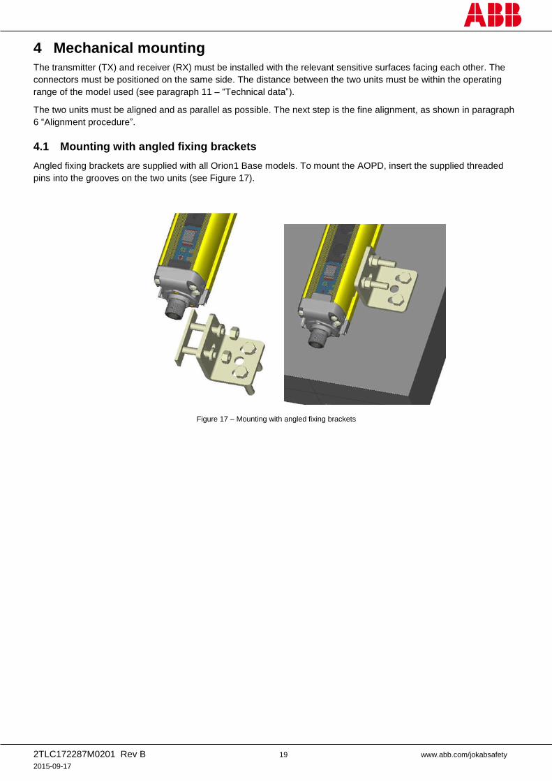
4.1 Mounting with angled fixing brackets
Angled fixing brackets are supplied with all Orion1 Base models. To mount the AOPD, insert the supplied threaded
pins into the grooves on the two units (see Figure 17).
Figure 17 – Mounting with angled fixing brackets
2TLC172287M0201 Rev B 20 www.abb.com/jokabsafety
2015-09-17
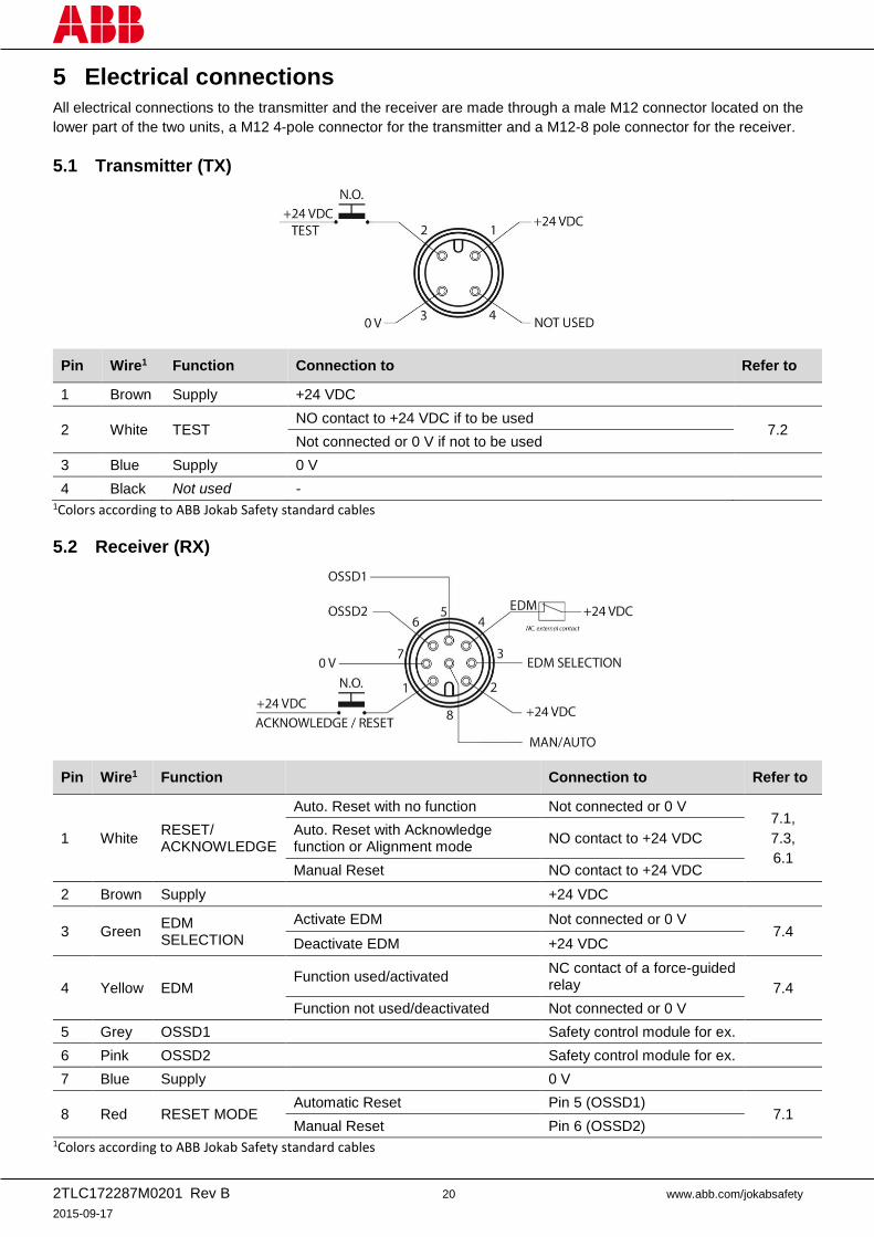
5 Electrical connections
All electrical connections to the transmitter and the receiver are made through a male M12 connector located on the
lower part of the two units, a M12 4-pole connector for the transmitter and a M12-8 pole connector for the receiver.
5.1 Transmitter (TX)
Pin Wire1 Function Connection to Refer to
1 Brown Supply +24 VDC
2 White TEST NO contact to +24 VDC if to be used
7.2 Not connected or 0 V if not to be used
3 Blue Supply 0 V
4 Black Not used - 1Colors according to ABB Jokab Safety standard cables
5.2 Receiver (RX)
Pin Wire1 Function Connection to Refer to
1 White RESET/ ACKNOWLEDGE
Auto. Reset with no function Not connected or 0 V 7.1,
7.3,
6.1
Auto. Reset with Acknowledge function or Alignment mode
NO contact to +24 VDC
Manual Reset NO contact to +24 VDC
2 Brown Supply +24 VDC
3 Green EDM SELECTION
Activate EDM Not connected or 0 V 7.4
Deactivate EDM +24 VDC
4 Yellow EDM Function used/activated
NC contact of a force-guided relay 7.4
Function not used/deactivated Not connected or 0 V
5 Grey OSSD1 Safety control module for ex.
6 Pink OSSD2 Safety control module for ex.
7 Blue Supply 0 V
8 Red RESET MODE Automatic Reset Pin 5 (OSSD1)
7.1 Manual Reset Pin 6 (OSSD2)
1Colors according to ABB Jokab Safety standard cables
2TLC172287M0201 Rev B 21 www.abb.com/jokabsafety
2015-09-17
5.3 Important notes on connections
For the correct functioning of the Orion1 Base light curtains, the following precautions regarding the electrical
connections have to be respected:
Use a suitably insulated low-voltage supply system type SELV or PELV.
Do not place connection cables in contact with or near high-voltage cables and/or cables undergoing high
current variations (e.g. motor power supplies, inverters, etc.).
Do not connect the OSSD wires of different AOPDs in the same multi-pole cable.
The TEST wire must be connected to the supply voltage of the AOPD through a NO push-button.
The ACKNOWLEDGE/RESET wire must be connected through a NO push-button to the supply voltage of the
Orion1 Base light curtain.
Warning! The TEST button must be located in such a way that the operator can check the hazard zone during any
test (see paragraph 7 – “Functions”.)
Warning! The ACKNOWLEDGE/RESET button must be located in such a way that the operator can check the hazard
zone during any reset operation (see paragraph 7 – “Functions”.)
The device is already equipped with internal overvoltage and overcurrent suppression devices. The use of
other external components is not recommended.
2TLC172287M0201 Rev B 22 www.abb.com/jokabsafety
2015-09-17
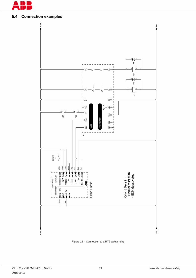
5.4 Connection examples
Figure 18 – Connection to a RT9 safety relay
2TLC172287M0201 Rev B 23 www.abb.com/jokabsafety
2015-09-17
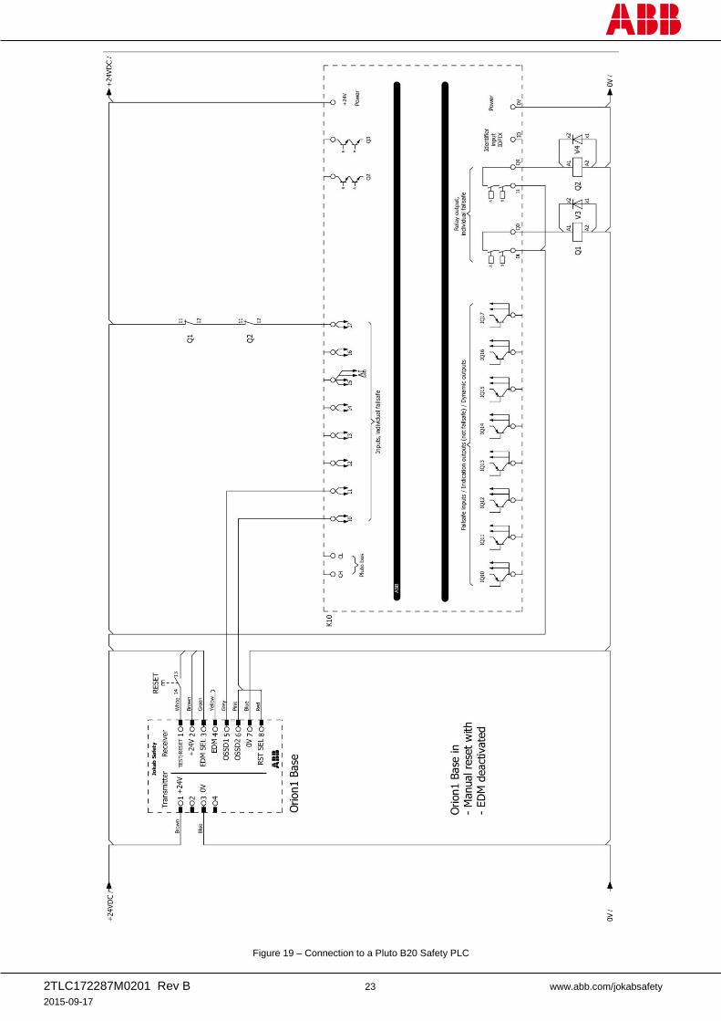
Figure 19 – Connection to a Pluto B20 Safety PLC
2TLC172287M0201 Rev B 24 www.abb.com/jokabsafety
2015-09-17
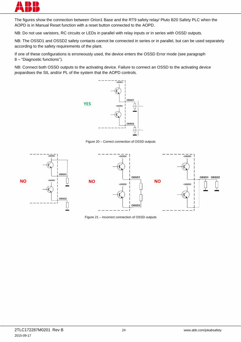
The figures show the connection between Orion1 Base and the RT9 safety relay/ Pluto B20 Safety PLC when the
AOPD is in Manual Reset function with a reset button connected to the AOPD.
NB: Do not use varistors, RC circuits or LEDs in parallel with relay inputs or in series with OSSD outputs.
NB: The OSSD1 and OSSD2 safety contacts cannot be connected in series or in parallel, but can be used separately
according to the safety requirements of the plant.
If one of these configurations is erroneously used, the device enters the OSSD Error mode (see paragraph
8 – “Diagnostic functions”).
NB: Connect both OSSD outputs to the activating device. Failure to connect an OSSD to the activating device
jeopardises the SIL and/or PL of the system that the AOPD controls.
Figure 20 – Correct connection of OSSD outputs
Figure 21 – Incorrect connection of OSSD outputs
NO NO NO
YES
2TLC172287M0201 Rev B 25 www.abb.com/jokabsafety
2015-09-17
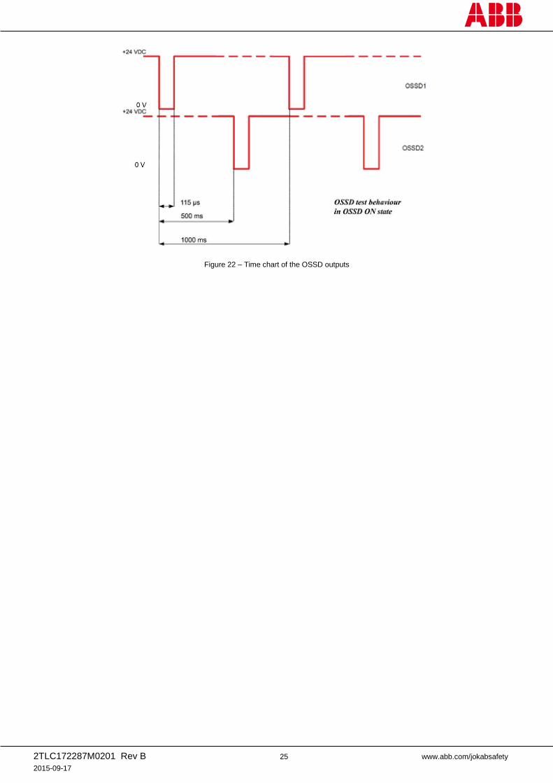
Figure 22 – Time chart of the OSSD outputs
2TLC172287M0201 Rev B 26 www.abb.com/jokabsafety
2015-09-17
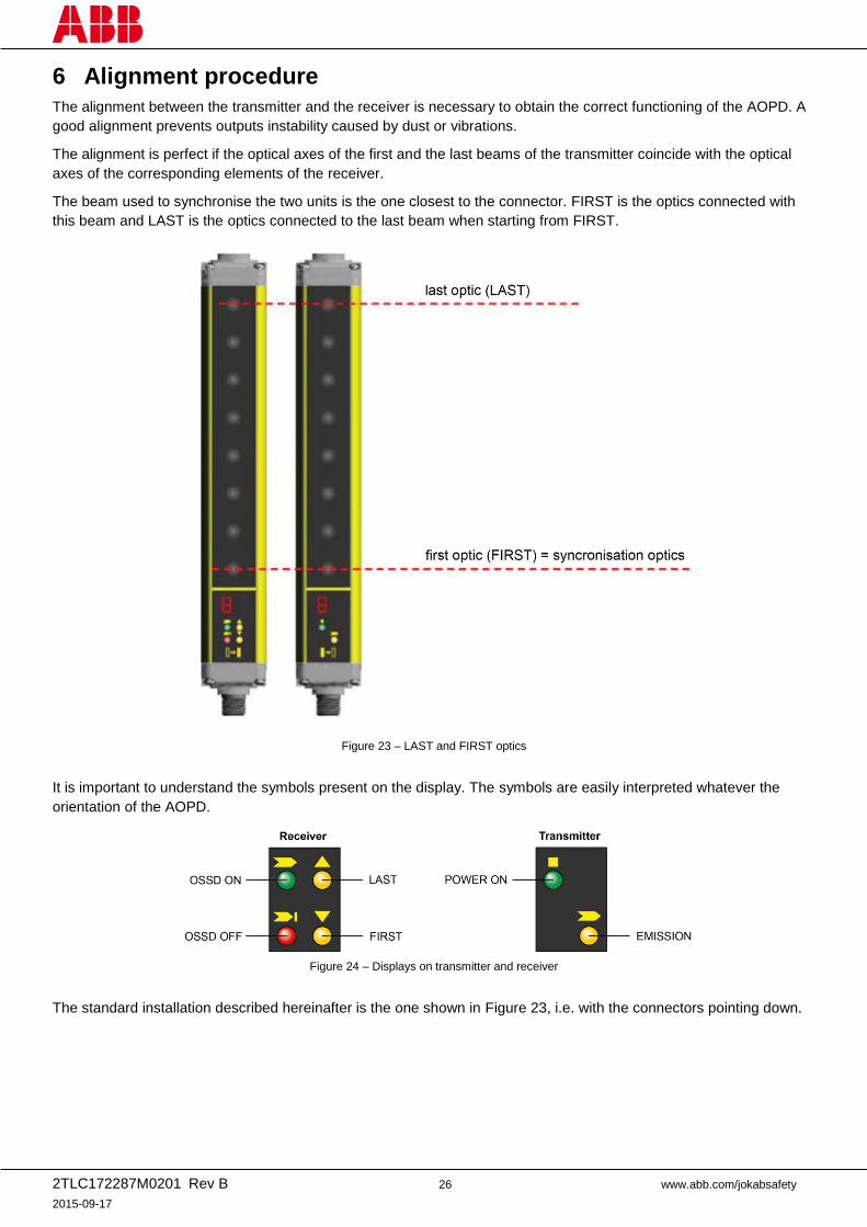
6 Alignment procedure
The alignment between the transmitter and the receiver is necessary to obtain the correct functioning of the AOPD. A
good alignment prevents outputs instability caused by dust or vibrations.
The alignment is perfect if the optical axes of the first and the last beams of the transmitter coincide with the optical
axes of the corresponding elements of the receiver.
The beam used to synchronise the two units is the one closest to the connector. FIRST is the optics connected with
this beam and LAST is the optics connected to the last beam when starting from FIRST.
Figure 23 – LAST and FIRST optics
It is important to understand the symbols present on the display. The symbols are easily interpreted whatever the
orientation of the AOPD.
Figure 24 – Displays on transmitter and receiver
The standard installation described hereinafter is the one shown in Figure 23, i.e. with the connectors pointing down.
2TLC172287M0201 Rev B 27 www.abb.com/jokabsafety
2015-09-17
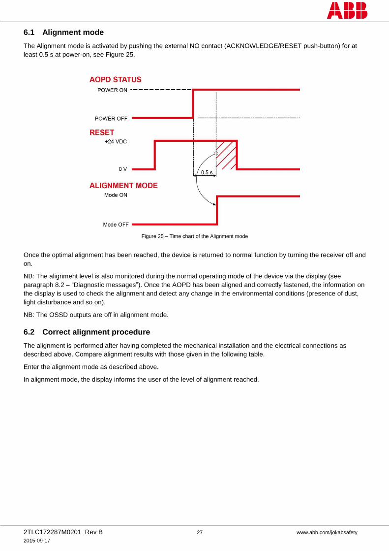
6.1 Alignment mode
The Alignment mode is activated by pushing the external NO contact (ACKNOWLEDGE/RESET push-button) for at
least 0.5 s at power-on, see Figure 25.
Figure 25 – Time chart of the Alignment mode
Once the optimal alignment has been reached, the device is returned to normal function by turning the receiver off and
on.
NB: The alignment level is also monitored during the normal operating mode of the device via the display (see
paragraph 8.2 – “Diagnostic messages”). Once the AOPD has been aligned and correctly fastened, the information on
the display is used to check the alignment and detect any change in the environmental conditions (presence of dust,
light disturbance and so on).
NB: The OSSD outputs are off in alignment mode.
6.2 Correct alignment procedure
The alignment is performed after having completed the mechanical installation and the electrical connections as
described above. Compare alignment results with those given in the following table.
Enter the alignment mode as described above.
In alignment mode, the display informs the user of the level of alignment reached.
2TLC172287M0201 Rev B 28 www.abb.com/jokabsafety
2015-09-17
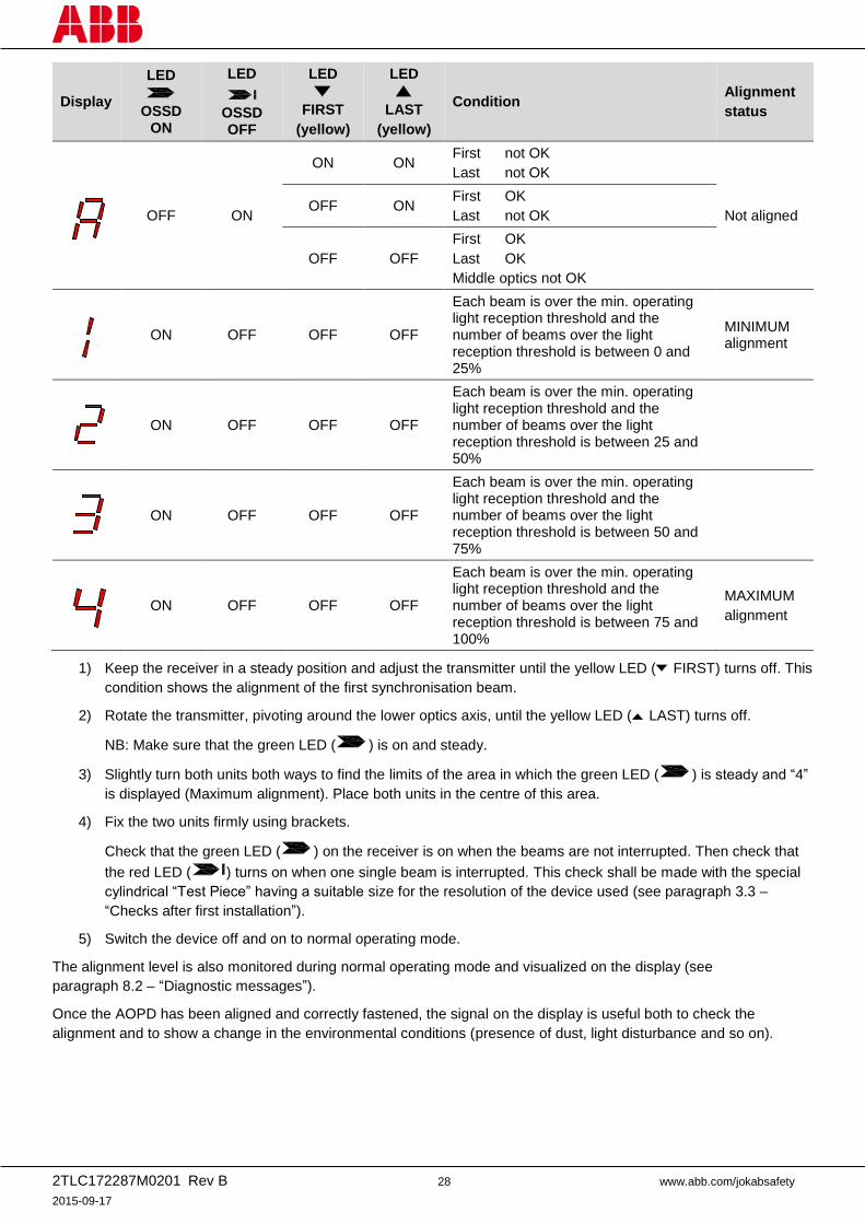
Display
LED
OSSD
ON
LED
OSSD OFF
LED
FIRST
(yellow)
LED
LAST
(yellow)
Condition Alignment
status
OFF ON
ON ON First not OK
Last not OK
Not aligned OFF ON
First OK
Last not OK
OFF OFF
First OK
Last OK
Middle optics not OK
ON OFF OFF OFF
Each beam is over the min. operating light reception threshold and the number of beams over the light reception threshold is between 0 and 25%
MINIMUM alignment
ON OFF OFF OFF
Each beam is over the min. operating light reception threshold and the number of beams over the light reception threshold is between 25 and 50%
ON OFF OFF OFF
Each beam is over the min. operating light reception threshold and the number of beams over the light reception threshold is between 50 and 75%
ON OFF OFF OFF
Each beam is over the min. operating light reception threshold and the number of beams over the light reception threshold is between 75 and 100%
MAXIMUM
alignment
1) Keep the receiver in a steady position and adjust the transmitter until the yellow LED ( FIRST) turns off. This
condition shows the alignment of the first synchronisation beam.
2) Rotate the transmitter, pivoting around the lower optics axis, until the yellow LED ( LAST) turns off.
NB: Make sure that the green LED ( ) is on and steady.
3) Slightly turn both units both ways to find the limits of the area in which the green LED ( ) is steady and “4”
is displayed (Maximum alignment). Place both units in the centre of this area.
4) Fix the two units firmly using brackets.
Check that the green LED ( ) on the receiver is on when the beams are not interrupted. Then check that
the red LED ( ) turns on when one single beam is interrupted. This check shall be made with the special
cylindrical “Test Piece” having a suitable size for the resolution of the device used (see paragraph 3.3 –
“Checks after first installation”).
5) Switch the device off and on to normal operating mode.
The alignment level is also monitored during normal operating mode and visualized on the display (see
paragraph 8.2 – “Diagnostic messages”).
Once the AOPD has been aligned and correctly fastened, the signal on the display is useful both to check the
alignment and to show a change in the environmental conditions (presence of dust, light disturbance and so on).
2TLC172287M0201 Rev B 29 www.abb.com/jokabsafety
2015-09-17
7 Functions
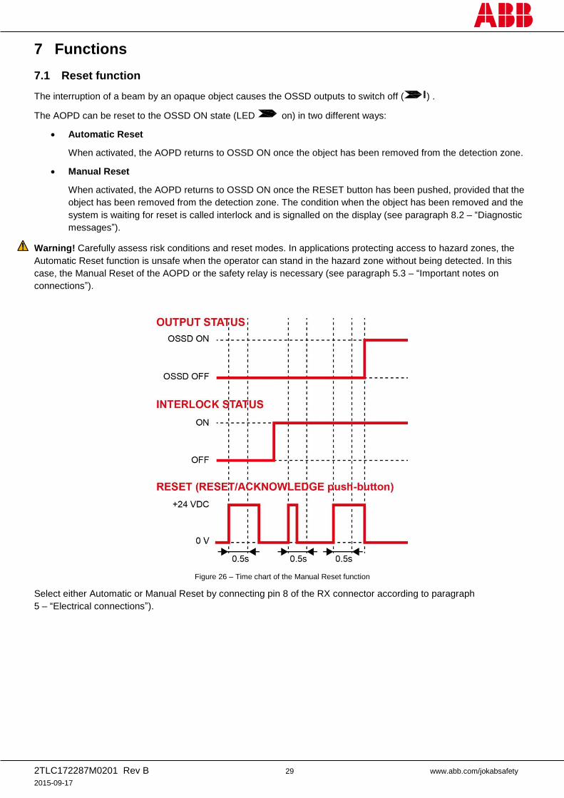
7.1 Reset function
The interruption of a beam by an opaque object causes the OSSD outputs to switch off ( ) .
The AOPD can be reset to the OSSD ON state (LED on) in two different ways:
Automatic Reset
When activated, the AOPD returns to OSSD ON once the object has been removed from the detection zone.
Manual Reset
When activated, the AOPD returns to OSSD ON once the RESET button has been pushed, provided that the
object has been removed from the detection zone. The condition when the object has been removed and the
system is waiting for reset is called interlock and is signalled on the display (see paragraph 8.2 – “Diagnostic
messages”).
Warning! Carefully assess risk conditions and reset modes. In applications protecting access to hazard zones, the
Automatic Reset function is unsafe when the operator can stand in the hazard zone without being detected. In this
case, the Manual Reset of the AOPD or the safety relay is necessary (see paragraph 5.3 – “Important notes on
connections”).
Figure 26 – Time chart of the Manual Reset function
Select either Automatic or Manual Reset by connecting pin 8 of the RX connector according to paragraph
5 – “Electrical connections”).
2TLC172287M0201 Rev B 30 www.abb.com/jokabsafety
2015-09-17
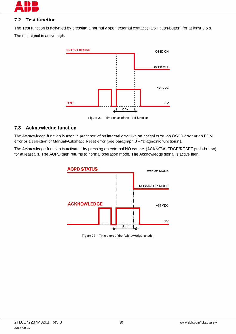
7.2 Test function
The Test function is activated by pressing a normally open external contact (TEST push-button) for at least 0.5 s.
The test signal is active high.
Figure 27 – Time chart of the Test function
7.3 Acknowledge function
The Acknowledge function is used in presence of an internal error like an optical error, an OSSD error or an EDM
error or a selection of Manual/Automatic Reset error (see paragraph 8 – “Diagnostic functions”).
The Acknowledge function is activated by pressing an external NO contact (ACKNOWLEDGE/RESET push-button)
for at least 5 s. The AOPD then returns to normal operation mode. The Acknowledge signal is active high.
Figure 28 – Time chart of the Acknowledge function
2TLC172287M0201 Rev B 31 www.abb.com/jokabsafety
2015-09-17
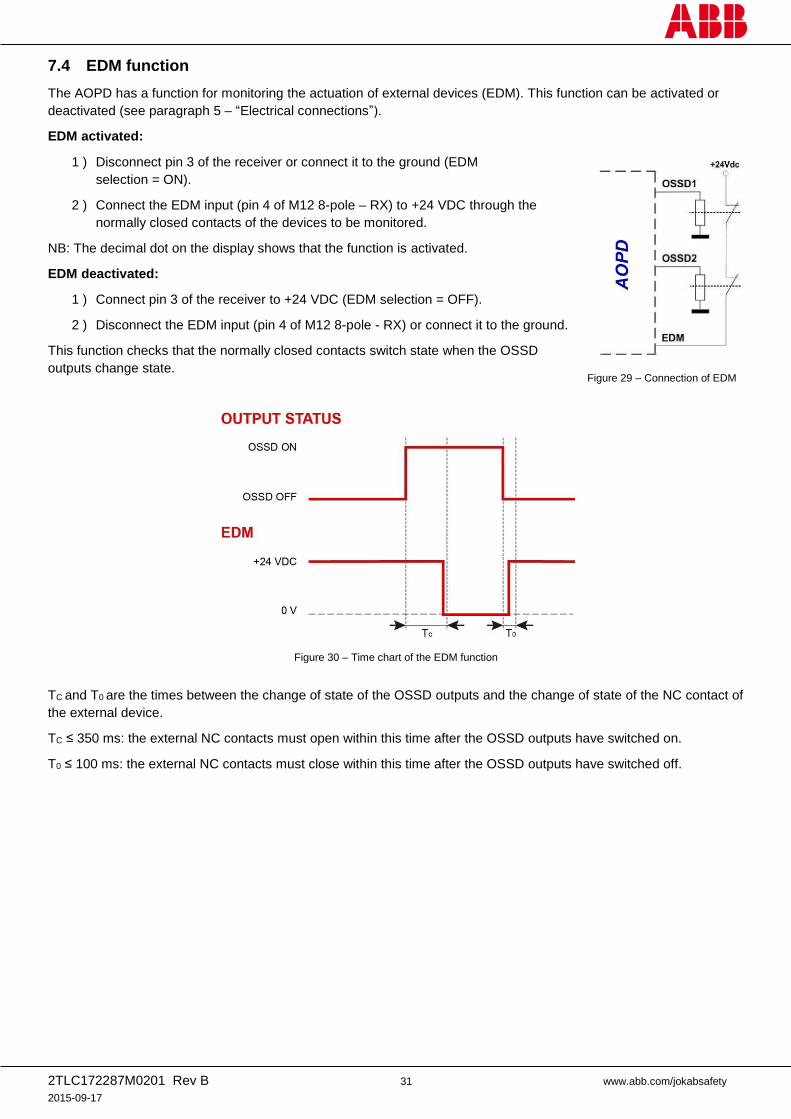
7.4 EDM function
The AOPD has a function for monitoring the actuation of external devices (EDM). This function can be activated or
deactivated (see paragraph 5 – “Electrical connections”).
EDM activated:
1 ) Disconnect pin 3 of the receiver or connect it to the ground (EDM
selection = ON).
2 ) Connect the EDM input (pin 4 of M12 8-pole – RX) to +24 VDC through the
normally closed contacts of the devices to be monitored.
NB: The decimal dot on the display shows that the function is activated.
EDM deactivated:
1 ) Connect pin 3 of the receiver to +24 VDC (EDM selection = OFF).
2 ) Disconnect the EDM input (pin 4 of M12 8-pole - RX) or connect it to the ground.
This function checks that the normally closed contacts switch state when the OSSD
outputs change state.
Figure 30 – Time chart of the EDM function
TC and T0 are the times between the change of state of the OSSD outputs and the change of state of the NC contact of
the external device.
TC ≤ 350 ms: the external NC contacts must open within this time after the OSSD outputs have switched on.
T0 ≤ 100 ms: the external NC contacts must close within this time after the OSSD outputs have switched off.
Figure 29 – Connection of EDM
2TLC172287M0201 Rev B 32 www.abb.com/jokabsafety
2015-09-17
8 Diagnostic functions
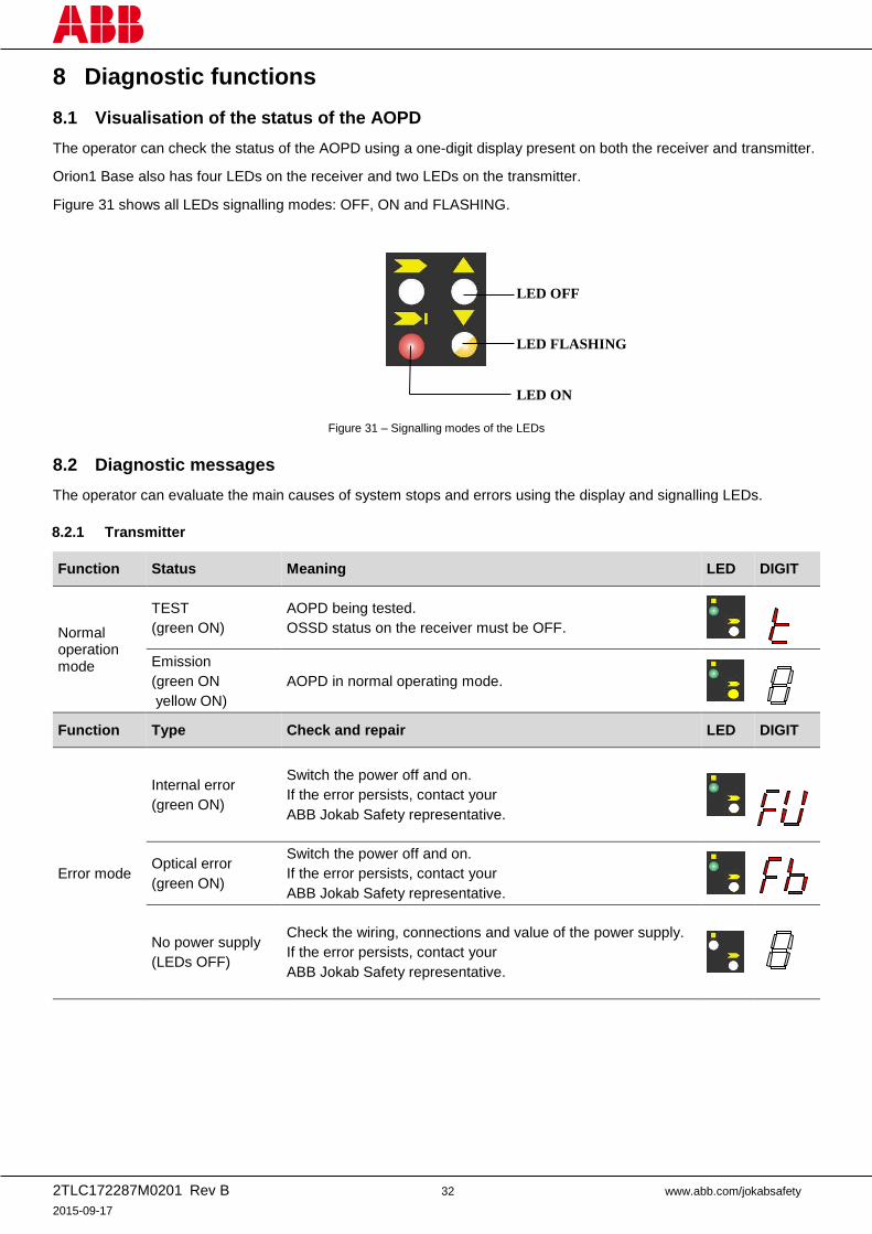
8.1 Visualisation of the status of the AOPD
The operator can check the status of the AOPD using a one-digit display present on both the receiver and transmitter.
Orion1 Base also has four LEDs on the receiver and two LEDs on the transmitter.
Figure 31 shows all LEDs signalling modes: OFF, ON and FLASHING.
Figure 31 – Signalling modes of the LEDs
8.2 Diagnostic messages
The operator can evaluate the main causes of system stops and errors using the display and signalling LEDs.
8.2.1 Transmitter
Function Status Meaning LED DIGIT
Normal operation mode
TEST
(green ON)
AOPD being tested.
OSSD status on the receiver must be OFF.
Emission
(green ON
yellow ON)
AOPD in normal operating mode.
Function Type Check and repair LED DIGIT
Error mode
Internal error
(green ON)
Switch the power off and on.
If the error persists, contact your
ABB Jokab Safety representative.
Optical error
(green ON)
Switch the power off and on.
If the error persists, contact your
ABB Jokab Safety representative.
No power supply
(LEDs OFF)
Check the wiring, connections and value of the power supply.
If the error persists, contact your
ABB Jokab Safety representative.
LED OFF
LED FLASHING
LED ON
2TLC172287M0201 Rev B 33 www.abb.com/jokabsafety
2015-09-17
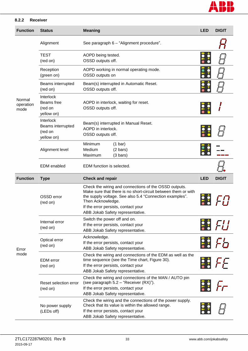
8.2.2 Receiver
Function Status Meaning LED DIGIT
Normal operation mode
Alignment See paragraph 6 – “Alignment procedure”.
TEST
(red on)
AOPD being tested.
OSSD outputs off.
Reception
(green on)
AOPD working in normal operating mode.
OSSD outputs on
Beams interrupted
(red on)
Beam(s) interrupted in Automatic Reset.
OSSD outputs off.
Interlock
Beams free
(red on
yellow on)
AOPD in interlock, waiting for reset.
OSSD outputs off.
Interlock
Beams interrupted
(red on
yellow on)
Beam(s) interrupted in Manual Reset.
AOPD in interlock.
OSSD outputs off.
Alignment level
Minimum (1 bar)
Medium (2 bars)
Maximum (3 bars)
EDM enabled EDM function is selected.
Function Type Check and repair LED DIGIT
Error mode
OSSD error
(red on)
Check the wiring and connections of the OSSD outputs. Make sure that there is no short-circuit between them or with the supply voltage. See also 5.4 “Connection examples”. Then Acknowledge.
If the error persists, contact your
ABB Jokab Safety representative.
Internal error
(red on)
Switch the power off and on.
If the error persists, contact your
ABB Jokab Safety representative.
Optical error
(red on)
Acknowledge.
If the error persists, contact your
ABB Jokab Safety representative.
EDM error
(red on)
Check the wiring and connections of the EDM as well as the time sequence (see the Time chart, Figure 30).
If the error persists, contact your
ABB Jokab Safety representative.
Reset selection error
(red on)
Check the wiring and connections of the MAN / AUTO pin (see paragraph 5.2 – “Receiver (RX)”).
If the error persists, contact your
ABB Jokab Safety representative.
No power supply
(LEDs off)
Check the wiring and the connections of the power supply. Check that its value is within the allowed range.
If the error persists, contact your
ABB Jokab Safety representative.
2TLC172287M0201 Rev B 34 www.abb.com/jokabsafety
2015-09-17
9 Periodical checks
The following is a list of recommended checks and maintenance operations that should be periodically carried-out by
qualified personnel.
Check that:
The AOPD remains in OSSD OFF state ( ) during beam interruption along the entire detection zone,
using the suitable “Test Piece” and following the Figure 16 scheme (see paragraph 3.3 Checks after first
installation”).
The AOPD is correctly aligned: press slightly the product side, in both directions, and check that the red LED
does not turn on.
The OSSD outputs switch off (the red LED turns ON and the controlled machine stops) when the Test
function is activated.
The stopping time of the machine, including the response times of the AOPD and of the machine, is within the
limits defined for the calculation of the minimum installation distance (see paragraph 2.4 – “Minimum
installation distance”).
The minimum installation distance between the hazard zone and the AOPD is in accordance with the
instructions included in paragraph 2.4 – “Minimum installation distance”.
Access of a person between the AOPD and the hazard zone of the machine is not possible, nor is it possible
for him/her to stay there without being detected.
Access to the hazard zone of the machine from any unprotected area is not possible.
The AOPD and the external electrical connections are not damaged.
The frequency of checks depends on the particular application and on the operating conditions of the AOPD.
2TLC172287M0201 Rev B 35 www.abb.com/jokabsafety
2015-09-17
10 Device maintenance
Orion1 Base light curtains do not require special maintenance operations.
To avoid the reduction of the operating distance, optic protective front surfaces must be cleaned at regular intervals.
Use soft cotton cloths damped in water. Do not apply too much pressure on the surface in order to avoid making it
opaque.
Do not use the following on plastic surfaces or on painted surfaces:
Alcohol or solvents
Wool or synthetic cloths
Paper or other abrasive materials.
2TLC172287M0201 Rev B 36 www.abb.com/jokabsafety
2015-09-17
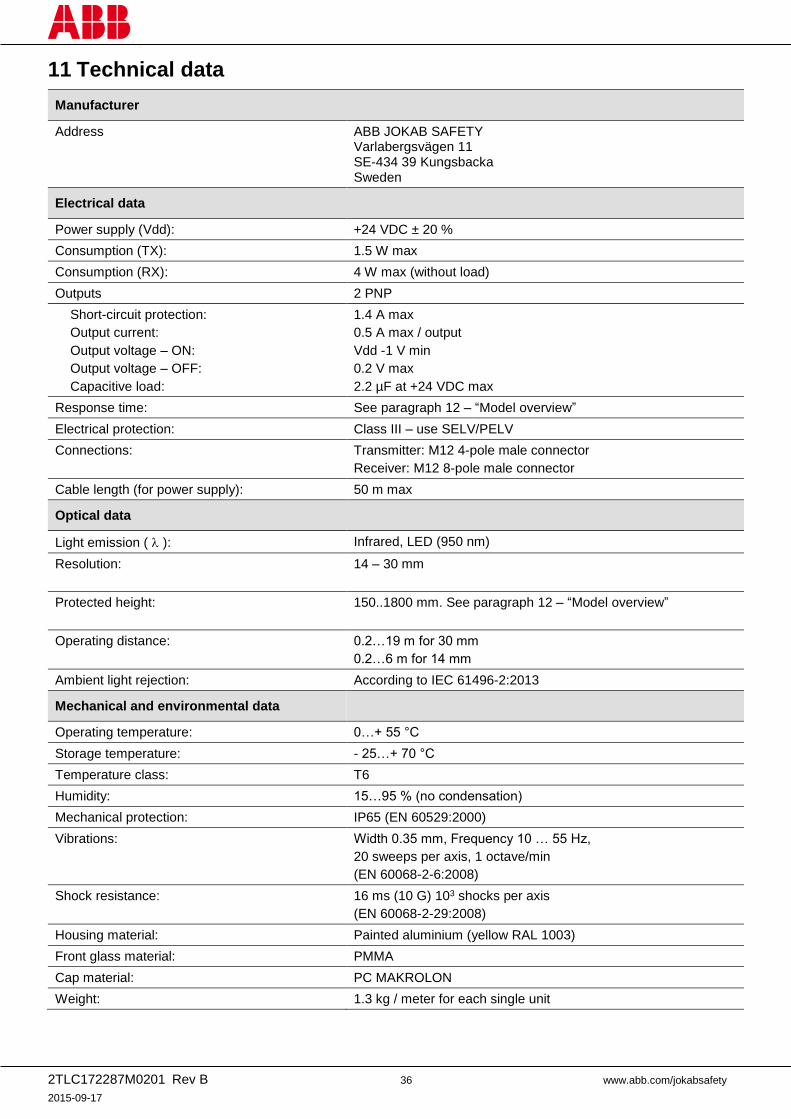
11 Technical data
Manufacturer
Address ABB JOKAB SAFETY Varlabergsvägen 11 SE-434 39 Kungsbacka Sweden
Electrical data
Power supply (Vdd): +24 VDC ± 20 %
Consumption (TX): 1.5 W max
Consumption (RX): 4 W max (without load)
Outputs 2 PNP
Short-circuit protection:
Output current:
Output voltage – ON:
Output voltage – OFF:
Capacitive load:
1.4 A max
0.5 A max / output
Vdd -1 V min
0.2 V max
2.2 µF at +24 VDC max
Response time: See paragraph 12 – “Model overview”
Electrical protection: Class III – use SELV/PELV
Connections: Transmitter: M12 4-pole male connector
Receiver: M12 8-pole male connector
Cable length (for power supply): 50 m max
Optical data
Light emission ( ): Infrared, LED (950 nm)
Resolution: 14 – 30 mm
Protected height: 150..1800 mm. See paragraph 12 – “Model overview”
Operating distance: 0.2…19 m for 30 mm
0.2…6 m for 14 mm
Ambient light rejection: According to IEC 61496-2:2013
Mechanical and environmental data
Operating temperature: 0…+ 55 °C
Storage temperature: - 25…+ 70 °C
Temperature class: T6
Humidity: 15…95 % (no condensation)
Mechanical protection: IP65 (EN 60529:2000)
Vibrations: Width 0.35 mm, Frequency 10 … 55 Hz,
20 sweeps per axis, 1 octave/min
(EN 60068-2-6:2008)
Shock resistance: 16 ms (10 G) 103 shocks per axis
(EN 60068-2-29:2008)
Housing material: Painted aluminium (yellow RAL 1003)
Front glass material: PMMA
Cap material: PC MAKROLON
Weight: 1.3 kg / meter for each single unit
2TLC172287M0201 Rev B 37 www.abb.com/jokabsafety
2015-09-17
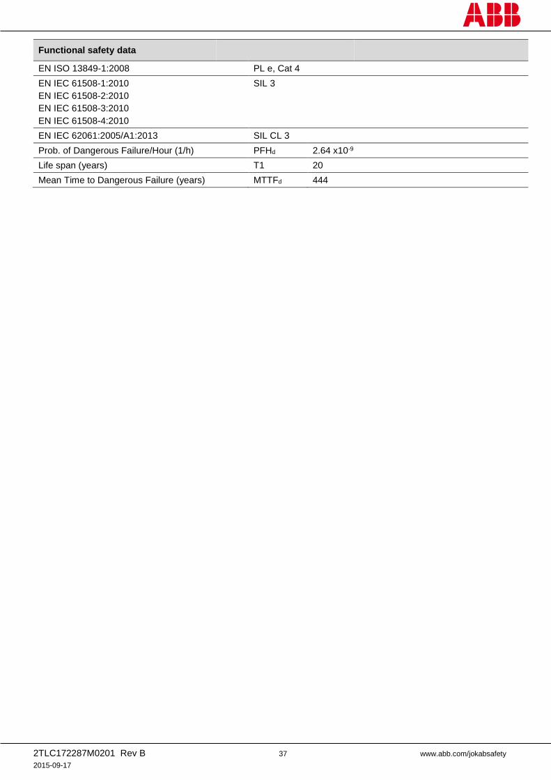
Functional safety data
EN ISO 13849-1:2008 PL e, Cat 4
EN IEC 61508-1:2010
EN IEC 61508-2:2010
EN IEC 61508-3:2010
EN IEC 61508-4:2010
SIL 3
EN IEC 62061:2005/A1:2013 SIL CL 3
Prob. of Dangerous Failure/Hour (1/h) PFHd 2.64 x10⁻⁹
Life span (years) T1 20
Mean Time to Dangerous Failure (years) MTTFd 444
2TLC172287M0201 Rev B 38 www.abb.com/jokabsafety
2015-09-17
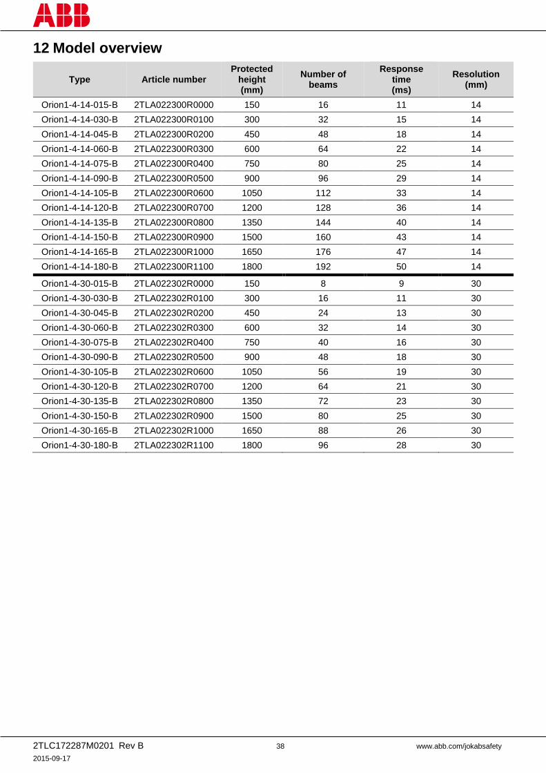
12 Model overview
Type Article number Protected
height (mm)
Number of beams
Response time (ms)
Resolution (mm)
Orion1-4-14-015-B 2TLA022300R0000 150 16 11 14
Orion1-4-14-030-B 2TLA022300R0100 300 32 15 14
Orion1-4-14-045-B 2TLA022300R0200 450 48 18 14
Orion1-4-14-060-B 2TLA022300R0300 600 64 22 14
Orion1-4-14-075-B 2TLA022300R0400 750 80 25 14
Orion1-4-14-090-B 2TLA022300R0500 900 96 29 14
Orion1-4-14-105-B 2TLA022300R0600 1050 112 33 14
Orion1-4-14-120-B 2TLA022300R0700 1200 128 36 14
Orion1-4-14-135-B 2TLA022300R0800 1350 144 40 14
Orion1-4-14-150-B 2TLA022300R0900 1500 160 43 14
Orion1-4-14-165-B 2TLA022300R1000 1650 176 47 14
Orion1-4-14-180-B 2TLA022300R1100 1800 192 50 14
Orion1-4-30-015-B 2TLA022302R0000 150 8 9 30
Orion1-4-30-030-B 2TLA022302R0100 300 16 11 30
Orion1-4-30-045-B 2TLA022302R0200 450 24 13 30
Orion1-4-30-060-B 2TLA022302R0300 600 32 14 30
Orion1-4-30-075-B 2TLA022302R0400 750 40 16 30
Orion1-4-30-090-B 2TLA022302R0500 900 48 18 30
Orion1-4-30-105-B 2TLA022302R0600 1050 56 19 30
Orion1-4-30-120-B 2TLA022302R0700 1200 64 21 30
Orion1-4-30-135-B 2TLA022302R0800 1350 72 23 30
Orion1-4-30-150-B 2TLA022302R0900 1500 80 25 30
Orion1-4-30-165-B 2TLA022302R1000 1650 88 26 30
Orion1-4-30-180-B 2TLA022302R1100 1800 96 28 30
2TLC172287M0201 Rev B 39 www.abb.com/jokabsafety
2015-09-17
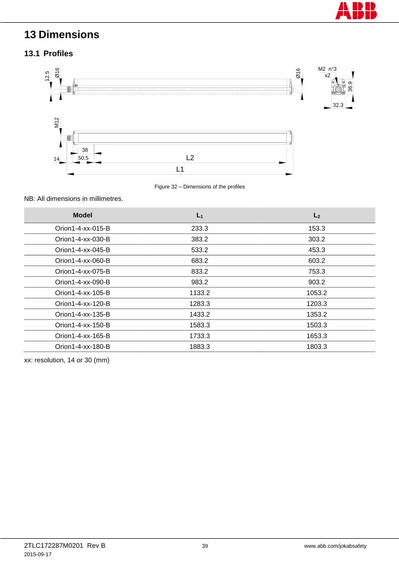
13 Dimensions
13.1 Profiles
Figure 32 – Dimensions of the profiles
NB: All dimensions in millimetres.
Model L1 L2
Orion1-4-xx-015-B 233.3 153.3
Orion1-4-xx-030-B 383.2 303.2
Orion1-4-xx-045-B 533.2 453.3
Orion1-4-xx-060-B 683.2 603.2
Orion1-4-xx-075-B 833.2 753.3
Orion1-4-xx-090-B 983.2 903.2
Orion1-4-xx-105-B 1133.2 1053.2
Orion1-4-xx-120-B 1283.3 1203.3
Orion1-4-xx-135-B 1433.2 1353.2
Orion1-4-xx-150-B 1583.3 1503.3
Orion1-4-xx-165-B 1733.3 1653.3
Orion1-4-xx-180-B 1883.3 1803.3
xx: resolution, 14 or 30 (mm)
38
L250.514
L1
Ø16
12
.5
M12
32.3
36
.9
M2 n°3
x2Ø16
2TLC172287M0201 Rev B 40 www.abb.com/jokabsafety
2015-09-17
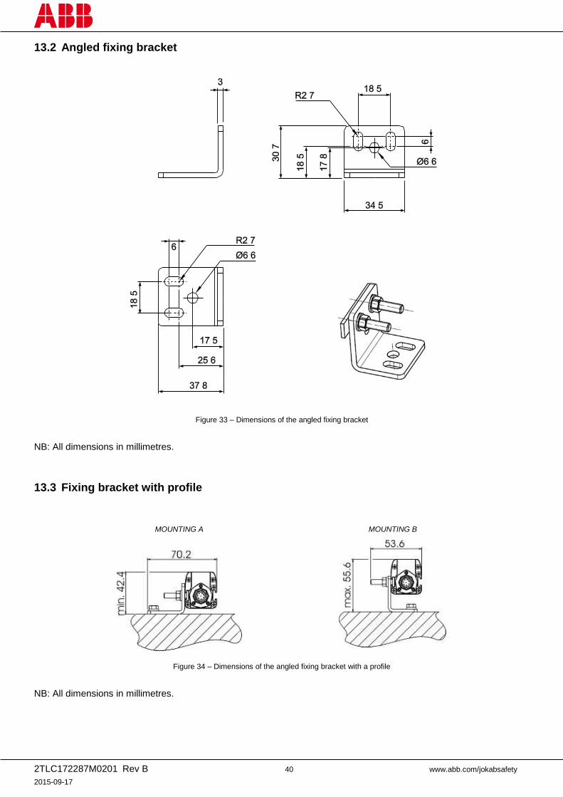
13.2 Angled fixing bracket
Figure 33 – Dimensions of the angled fixing bracket
NB: All dimensions in millimetres.
13.3 Fixing bracket with profile
MOUNTING A
MOUNTING B
Figure 34 – Dimensions of the angled fixing bracket with a profile
NB: All dimensions in millimetres.
2TLC172287M0201 Rev B 41 www.abb.com/jokabsafety
2015-09-17
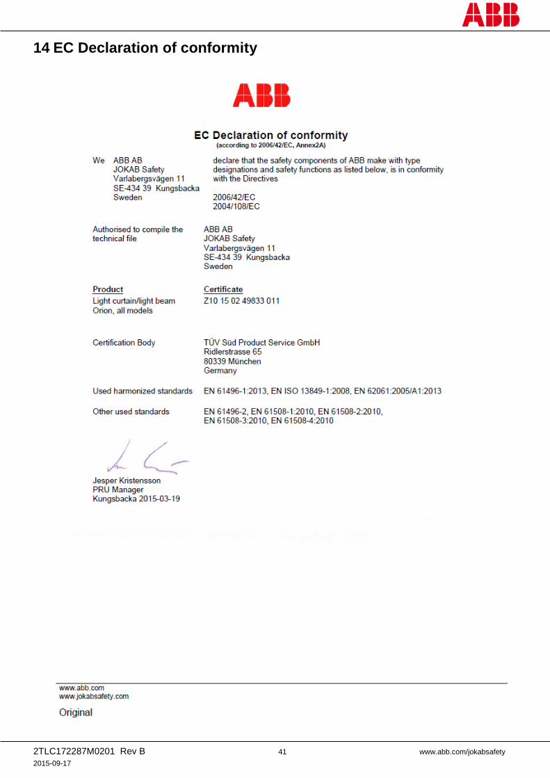
14 EC Declaration of conformity


![Orion1 Base QGOrion1 Base Safety light curtains Type 4 Active Opto-electronic Protective Device (AOPD) [EN] with the product in a digital format and can also While every effort has](https://img.pdfslide.us/doc/110x75/613186361ecc51586944ca4a/orion1-base-qg-orion1-base-safety-light-curtains-type-4-active-opto-electronic-protective.jpg)