Embed Size (px)
Citation preview
Warning: (1) Periodic inspection and maintenance of Corken products is essential. (2) Inspection, maintenance and installation of Corken products must be made only by experienced, trained and qualified personnel. (3) Maintenance, use and installation of Corken products must comply with Corken instructions, applicable laws and safety standards (such as NFPA Pamphlet 58 for LP-Gas and ANSI K61.1-1972 for Anhydrous Ammonia). (4) Transfer of toxic, dangerous, flammable or explosive substances using Corken products is at user’s risk and equipment should be operated only by qualified personnel according to applicable laws and safety standards.
WFD551 Compressor Shown
Installation, Operation& Maintenance Manual
D-Style Two-Stage Gas CompressorModel WFD551
ORIGINAL INSTRUCTIONS IE106

WarningInstall, use and maintain this equipment according to Corken, Inc. instructions and all applicable federal, state, local laws and codes, and NFPA Pamphlet 58 for LP-Gas or ANSI K61.1-1989 for Anhydrous Ammonia. Periodic inspection and maintenance is essential.
Corken One Year Limited WarrantyCorken, Inc. warrants that its products will be free from defects in material and workmanship for a period of 12 months following date of purchase from Corken. Corken products which fail within the warranty period due to defects in material or workmanship will be repaired or replaced at Corken’s option, when returned freight prepaid to: Corken, Inc., 3805 N.W. 36th Street, Oklahoma City, Oklahoma 73112.
Parts subject to wear or abuse, such as mechanical seals, blades, piston rings, valves, and packing, and other parts showing signs of abuse are not covered by this limited warranty. Also, equipment, parts and accessories not manufactured by Corken but furnished with Corken products are not covered by this limited warranty and purchaser must look to the original manufacturer’s warranty, if any. This limited warranty is void if the Corken product has been altered or repaired without the consent of Corken.
ALL IMPLIED WARRANTIES, INCLUDING ANY IMPLIED WARRANTY OF MERCHANTABILITY OR FITNESS FOR A PARTICULAR PURPOSE, ARE EXPRESSLY NEGATED TO THE EXTENT PERMITTED BY LAW AND SHALL IN NO EVENT EXTEND BEYOND THE EXPRESSED WARRANTY PERIOD.
Corken disclaims any liability for consequential damages due to breach of any written or implied warranty on Corken products. Transfer of toxic, dangerous, flammable or explosive substances using Corken products is at the user’s risk. Such substances should be handled by experienced, trained personnel in compliance with governmental and industrial safety standards.
Contacting The FactoryFor your convenience, the model number and serial number are given on the compressor nameplate. Space is provided below for you to keep a written record of this information.
Always include the model number and serial number when ordering parts.
Model No.
Serial No.
Date Purchased
Date Installed
Purchased From
Installed By
2
Table of ContentsCOMPRESSOR FEATURES . . . . . . . . . . . . . . . . . . . . . . . . . . . . . . . . . . . . . . . . . . . . . . . . . . . . . . . . . . . . . . . . . . . . . 4
CHAPTER 1—INSTALLING YOUR CORKEN COMPRESSOR . . . . . . . . . . . . . . . . . . . . . . . . . . . . . . . . . . . . . . . . . . 5
1.1 Location . . . . . . . . . . . . . . . . . . . . . . . . . . . . . . . . . . . . . . . . . . . . . . . . . . . . . . . . . . . . . . . . . . . . . . . . . . . . . . . . . 5
1.2 Foundation . . . . . . . . . . . . . . . . . . . . . . . . . . . . . . . . . . . . . . . . . . . . . . . . . . . . . . . . . . . . . . . . . . . . . . . . . . . . . . . 5
1.3 Piping . . . . . . . . . . . . . . . . . . . . . . . . . . . . . . . . . . . . . . . . . . . . . . . . . . . . . . . . . . . . . . . . . . . . . . . . . . . . . . . . . . . 5
1.4 Driver Installation/Flywheels . . . . . . . . . . . . . . . . . . . . . . . . . . . . . . . . . . . . . . . . . . . . . . . . . . . . . . . . . . . . . . . . . 6
1.5 Crankcase Lubrication . . . . . . . . . . . . . . . . . . . . . . . . . . . . . . . . . . . . . . . . . . . . . . . . . . . . . . . . . . . . . . . . . . . . . . 6
1.6 Purging, Padding, Venting and Draining of Distance Pieces . . . . . . . . . . . . . . . . . . . . . . . . . . . . . . . . . . . . . . . . . 7
1.7 Relief Valves . . . . . . . . . . . . . . . . . . . . . . . . . . . . . . . . . . . . . . . . . . . . . . . . . . . . . . . . . . . . . . . . . . . . . . . . . . . . . . 7
1.8 Shutdown/Alarm Devices . . . . . . . . . . . . . . . . . . . . . . . . . . . . . . . . . . . . . . . . . . . . . . . . . . . . . . . . . . . . . . . . . . . . 8
1.9 Compressor Cooling . . . . . . . . . . . . . . . . . . . . . . . . . . . . . . . . . . . . . . . . . . . . . . . . . . . . . . . . . . . . . . . . . . . . . . 10
CHAPTER 2—STARTING UP YOUR CORKEN COMPRESSOR . . . . . . . . . . . . . . . . . . . . . . . . . . . . . . . . . . . . . . . 10
2.1 Inspection After Extended Storage . . . . . . . . . . . . . . . . . . . . . . . . . . . . . . . . . . . . . . . . . . . . . . . . . . . . . . . . . . . 10
2.2 Flywheel and V-belt Alignment . . . . . . . . . . . . . . . . . . . . . . . . . . . . . . . . . . . . . . . . . . . . . . . . . . . . . . . . . . . . . . 10
2.3 Crankcase Oil Pressure Adjustment . . . . . . . . . . . . . . . . . . . . . . . . . . . . . . . . . . . . . . . . . . . . . . . . . . . . . . . . . . 11
2.4 Startup Check List . . . . . . . . . . . . . . . . . . . . . . . . . . . . . . . . . . . . . . . . . . . . . . . . . . . . . . . . . . . . . . . . . . . . . . . . 11
CHAPTER 3—ROUTINE MAINTENANCE CHART . . . . . . . . . . . . . . . . . . . . . . . . . . . . . . . . . . . . . . . . . . . . . . . . . . 12
CHAPTER 4—ROUTINE SERVICE AND REPAIR PROCEDURES . . . . . . . . . . . . . . . . . . . . . . . . . . . . . . . . . . . . . . 13
4.1 Valves . . . . . . . . . . . . . . . . . . . . . . . . . . . . . . . . . . . . . . . . . . . . . . . . . . . . . . . . . . . . . . . . . . . . . . . . . . . . . . . . . . 13
4.1.1 Reverse Unloader Option . . . . . . . . . . . . . . . . . . . . . . . . . . . . . . . . . . . . . . . . . . . . . . . . . . . . . . . . . . . . . . . . . 14
4.2 Heads . . . . . . . . . . . . . . . . . . . . . . . . . . . . . . . . . . . . . . . . . . . . . . . . . . . . . . . . . . . . . . . . . . . . . . . . . . . . . . . . . . 14
4.3 Piston Rings and Piston Ring Expanders Replacement . . . . . . . . . . . . . . . . . . . . . . . . . . . . . . . . . . . . . . . . . . . 14
4.4 Piston Replacement . . . . . . . . . . . . . . . . . . . . . . . . . . . . . . . . . . . . . . . . . . . . . . . . . . . . . . . . . . . . . . . . . . . . . . . 15
4.5 Piston Rod Packing Adjustment . . . . . . . . . . . . . . . . . . . . . . . . . . . . . . . . . . . . . . . . . . . . . . . . . . . . . . . . . . . . . 15
4.6 Cylinder Replacement . . . . . . . . . . . . . . . . . . . . . . . . . . . . . . . . . . . . . . . . . . . . . . . . . . . . . . . . . . . . . . . . . . . . . 16
4.7 Bearing Replacement for Crankcase and Connecting Rod . . . . . . . . . . . . . . . . . . . . . . . . . . . . . . . . . . . . . . . . 17
4.8 Oil Pump Inspection. . . . . . . . . . . . . . . . . . . . . . . . . . . . . . . . . . . . . . . . . . . . . . . . . . . . . . . . . . . . . . . . . . . . . . . 19
CHAPTER 5—EXTENDED STORAGE PROCEDURES . . . . . . . . . . . . . . . . . . . . . . . . . . . . . . . . . . . . . . . . . . . . . . . 19
APPENDICES
A. Model Number Identification Code . . . . . . . . . . . . . . . . . . . . . . . . . . . . . . . . . . . . . . . . . . . . . . . . . . . . . . . . . . . . 20
B. Material Specifications . . . . . . . . . . . . . . . . . . . . . . . . . . . . . . . . . . . . . . . . . . . . . . . . . . . . . . . . . . . . . . . . . . . . . 21
C. Outline Dimensions . . . . . . . . . . . . . . . . . . . . . . . . . . . . . . . . . . . . . . . . . . . . . . . . . . . . . . . . . . . . . . . . . . . . . . . . 24
D. Troubleshooting . . . . . . . . . . . . . . . . . . . . . . . . . . . . . . . . . . . . . . . . . . . . . . . . . . . . . . . . . . . . . . . . . . . . . . . . . . . 26
E. Assembly Details . . . . . . . . . . . . . . . . . . . . . . . . . . . . . . . . . . . . . . . . . . . . . . . . . . . . . . . . . . . . . . . . . . . . . . . . . . 27
3
Compressor Features
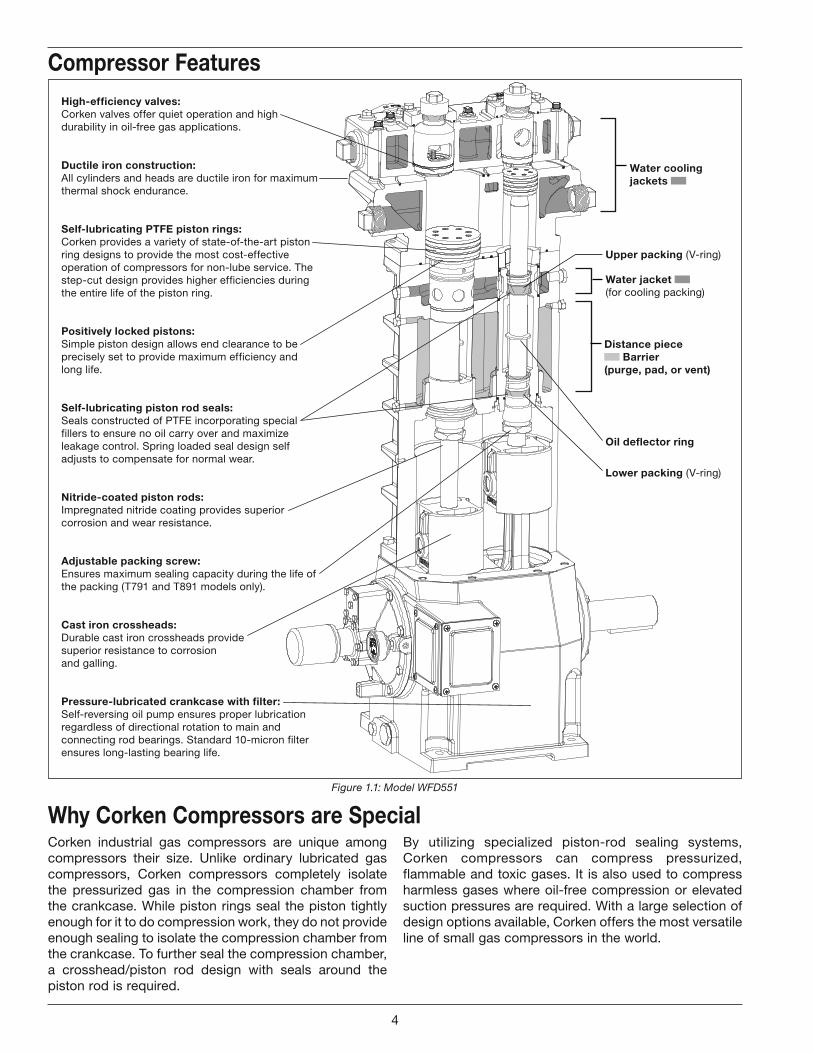
Figure 1.1: Model WFD551
Corken industrial gas compressors are unique among compressors their size. Unlike ordinary lubricated gas compressors, Corken compressors completely isolate the pressurized gas in the compression chamber from the crankcase. While piston rings seal the piston tightly enough for it to do compression work, they do not provide enough sealing to isolate the compression chamber from the crankcase. To further seal the compression chamber, a crosshead/piston rod design with seals around the piston rod is required.
By utilizing specialized piston-rod sealing systems, Corken compressors can compress pressurized, flammable and toxic gases. It is also used to compress harmless gases where oil-free compression or elevated suction pressures are required. With a large selection of design options available, Corken offers the most versatile line of small gas compressors in the world.
Why Corken Compressors are Special
High-efficiency valves:Corken valves offer quiet operation and high durability in oil-free gas applications.
Ductile iron construction:All cylinders and heads are ductile iron for maximum thermal shock endurance.
Self-lubricating PTFE piston rings:Corken provides a variety of state-of-the-art piston ring designs to provide the most cost-effective operation of compressors for non-lube service. The step-cut design provides higher efficiencies during the entire life of the piston ring.
Positively locked pistons:Simple piston design allows end clearance to be precisely set to provide maximum efficiency and long life.
Self-lubricating piston rod seals:Seals constructed of PTFE incorporating special fillers to ensure no oil carry over and maximize leakage control. Spring loaded seal design self adjusts to compensate for normal wear.
Nitride-coated piston rods:Impregnated nitride coating provides superior corrosion and wear resistance.
Adjustable packing screw: Ensures maximum sealing capacity during the life of the packing (T791 and T891 models only).
Cast iron crossheads:Durable cast iron crossheads providesuperior resistance to corrosionand galling.
Pressure-lubricated crankcase with filter:Self-reversing oil pump ensures proper lubrication regardless of directional rotation to main and connecting rod bearings. Standard 10-micron filter ensures long-lasting bearing life.
Lower packing (V-ring)
Upper packing (V-ring)
Water jacket (for cooling packing)
Water cooling jackets
Distance piece Barrier
(purge, pad, or vent)
Oil deflector ring
4
1.1 Location
WARNING
Compressor must be installed in a well ventilated area.
Corken compressors are designed and manufactured for outdoor duty. For applications where the compressor will be subjected to extreme conditions for extended periods such as corrosive environments, arctic conditions, etc., consult Corken. Check local safety regulations and building codes to assure installation will meet local safety standards.
WARNING
Corken compressors handling toxic or flammable gases such as LPG/NH3 should be located outdoors in a well ventilated area. A
minimum of 18 inches (45 cm) clearance between the compressor and the nearest wall is recommended. This will make it accessible from all sides and provide unrestricted air flow for adequate cooling.
Noise Level: Many factors affect the noise level generated by a compressor installation. Several of these, including motor noise, piping vibration, foundation/skid design, and surrounding structures are outside Corken’s control. The use of sufficient pipe supports, flexible hoses, and proper baseplate/skid support will all reduce noise. Thus, Corken cannot guarantee a particular noise level from our compressors. However, noise levels from a properly installed Corken compressor should not exceed 85dBa at three feet.
1.2 FoundationProper foundations are essential for a smooth running compression system. Corken recommends the compressor be attached to a concrete slab at least 8 inches thick with a 2 inch skirt around the circumference of the baseplate. The baseplate should be securely anchored into the foundation by 1/2 inch diameter “J” bolts that are 12 inches long. The total mass of the foundation should be approximately twice the weight of the compressor system (compressor, baseplate, motor, etc.). See figure 1.2 for details.
After leveling and bolting down the baseplate, the volume beneath the channel iron baseplate can be grouted to prevent flexing of the top portion of the baseplate and the “J” bolt that extends beyond the foundation. The grout also improves the dampening capabilities of the foundation by creating a solid interface between the compressor and foundation.
On some of the longer baseplates, such as with the 107 mountings, a 3 inch hole can be cut in the baseplate for filling the middle section of the baseplate with grout.
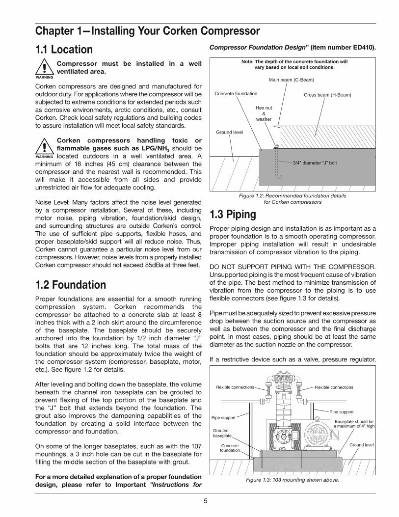
For a more detailed explanation of a proper foundation design, please refer to Important "Instructions for
Compressor Foundation Design” (item number ED410).
Main beam (C-Beam)
Cross beam (H-Beam)
&washer
Note: The depth of the concrete foundation willvary based on local soil conditions.
Figure 1.2: Recommended foundation detailsfor Corken compressors
1.3 PipingProper piping design and installation is as important as a proper foundation is to a smooth operating compressor. Improper piping installation will result in undesirable transmission of compressor vibration to the piping.
DO NOT SUPPORT PIPING WITH THE COMPRESSOR. Unsupported piping is the most frequent cause of vibration of the pipe. The best method to minimize transmission of vibration from the compressor to the piping is to use flexible connectors (see figure 1.3 for details).
Pipe must be adequately sized to prevent excessive pressure drop between the suction source and the compressor as well as between the compressor and the final discharge point. In most cases, piping should be at least the same diameter as the suction nozzle on the compressor.
If a restrictive device such as a valve, pressure regulator,
Chapter 1—Installing Your Corken Compressor
Ground levelConcretefoundation
Baseplate should be
Groutedbaseplate
Pipe supportPipe support
Flexible connections Flexible connections
Figure 1.3: 103 mounting shown above.
5
or back-check valve is to be installed in the compressor’s suction line, care must be taken. The suction line volume between the restrictive device and the compressor suction nozzle must be at least ten times the swept cylinder volume.
On liquefied gas applications such as LPG/NH3, it is of extreme importance to prevent the entry of liquid into the compressor. Installing a liquid trap on the inlet side will prevent liquid from entering the compressor.
It is of equal importance to protect the discharge side of the compressor from liquid entry. This may be done by installing a check valve on the discharge side of the compressor and using a piping design that does not allow liquid to gravity drain into the compressor.
For vapor recovery applications, be certain to install a check valve on vapor lines discharging to the liquid space of the tank.
All piping must be in accordance with the laws and codes governing the service. In the United States, the following codes apply:
For LP Gas—The National Fire Protection Association Pamphlet No. 58, Standard for the Storage and Handling of Liquefied Petroleum Gases.
For Ammonia—The American National Standards Institute, Inc., K61.1-1989, Storage and Handling of Anhydrous Ammonia.
Copies of these are available from NFPA, 60 Baterymarch Street, Boston, Mass, 02110 and ANSI, 1430 Broadway, New York, N.Y., 10018. Install, use and maintain this equipment according to Corken instructions and all applicable federal, state, and local laws and previously mentioned codes. Other laws may apply in different industries and applications.
1.4 Driver Installation/FlywheelsCorken vertical compressors may be driven by either electric motors or combustion engines (gasoline, diesel, natural gas, etc.).
WARNING
Never operate a reciprocating compressor without a flywheel.
Drivers should be selected so the compressor operates between 400 and 825 RPM. The unit must not be operated without the flywheel or severe torsional imbalances will result that could cause vibration and a high horsepower requirement. The flywheel should never be replaced by another pulley unless it has a higher wk2 value than the flywheel.
Humid climates can cause problems with explosion proof motors. The normal breathing of the motor and alternating between being warm when running and cool when stopped can cause moist air to be drawn into the
motor. This moist air will condense, and may eventually add enough water inside the motor to cause it to fail. To prevent this, make a practice of running the motor at least once a week on a bright, dry day for an hour or so without the V-belts. During this period of time, the motor will heat up and vaporize the condensed moisture. No motor manufacturer will guarantee their explosion proof or totally enclosed (TEFC) motor against damage from moisture.
For installation with engine drivers, thoroughly review instructions from the engine manufacturer to assure the unit is properly installed.
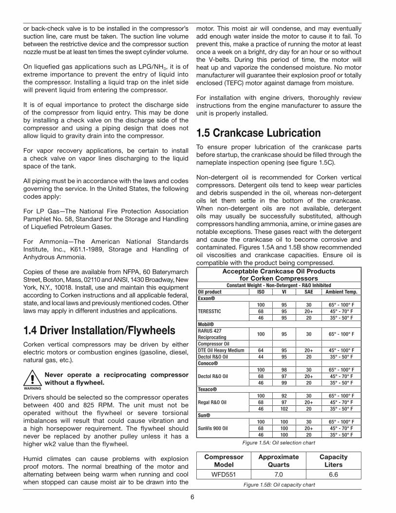
1.5 Crankcase LubricationTo ensure proper lubrication of the crankcase parts before startup, the crankcase should be filled through the nameplate inspection opening (see figure 1.5C).
Non-detergent oil is recommended for Corken vertical compressors. Detergent oils tend to keep wear particles and debris suspended in the oil, whereas non-detergent oils let them settle in the bottom of the crankcase. When non-detergent oils are not available, detergent oils may usually be successfully substituted, although compressors handling ammonia, amine, or imine gases are notable exceptions. These gases react with the detergent and cause the crankcase oil to become corrosive and contaminated. Figures 1.5A and 1.5B show recommended oil viscosities and crankcase capacities. Ensure oil is compatible with the product being compressed.
CompressorModel
ApproximateQuarts
CapacityLiters
WFD551 7.0 6.6
Figure 1.5B: Oil capacity chart
Acceptable Crankcase Oil Productsfor Corken Compressors
Constant Weight - Non-Detergent - R&O InhibitedOil product ISO VI SAE Ambient Temp.Exxon®
TERESSTIC100 95 30 65° - 100° F68 95 20+ 45° - 70° F46 95 20 35° - 50° F
Mobil®RARUS 427 Reciprocating
100 95 30 65° - 100° F
Compressor OilDTE Oil Heavy Medium 64 95 20+ 45° - 100° FDectol R&O Oil 44 95 20 35° - 50° FConoco®
Dectol R&O Oil100 98 30 65° - 100° F68 97 20+ 45° - 70° F46 99 20 35° - 50° F
Texaco®
Regal R&O Oil100 92 30 65° - 100° F68 97 20+ 45° - 70° F46 102 20 35° - 50° F
Sun®
SunVis 900 Oil100 100 30 65° - 100° F68 100 20+ 45° - 70° F46 100 20 35° - 50° F
Figure 1.5A: Oil selection chart
6
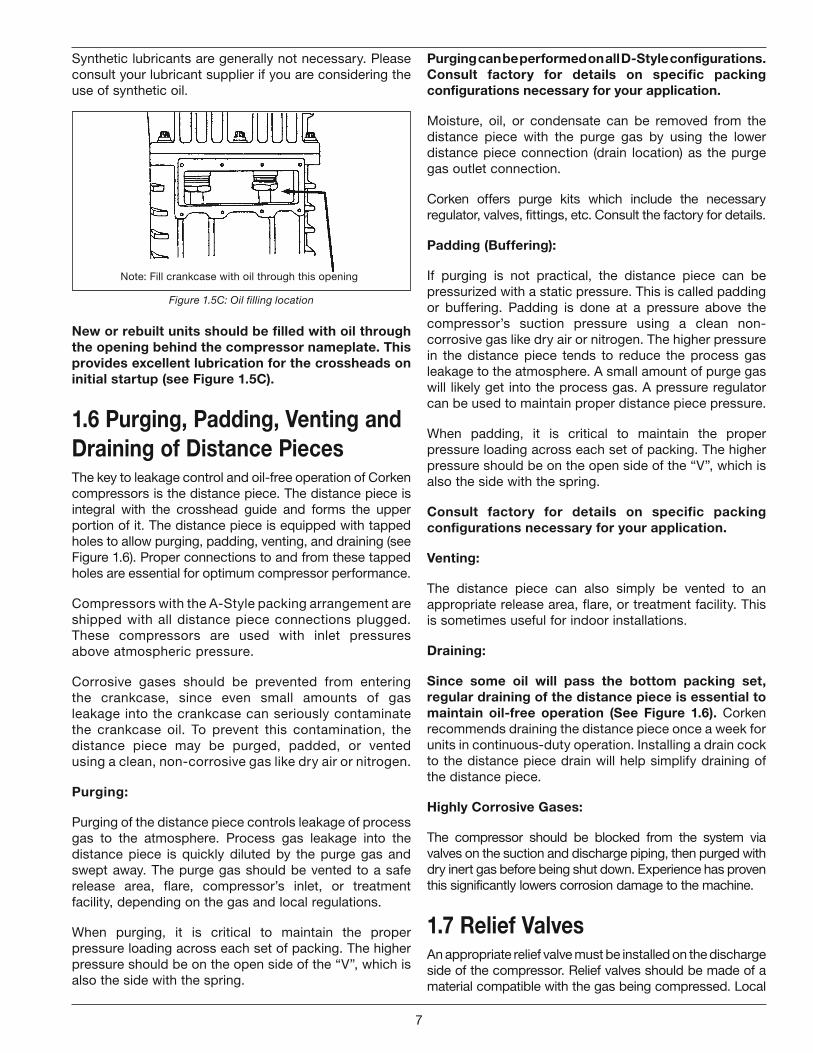
Synthetic lubricants are generally not necessary. Please consult your lubricant supplier if you are considering the use of synthetic oil.
Note: Fill crankcase with oil through this opening
Figure 1.5C: Oil filling location
New or rebuilt units should be filled with oil through the opening behind the compressor nameplate. This provides excellent lubrication for the crossheads on initial startup (see Figure 1.5C).
1.6 Purging, Padding, Venting and Draining of Distance PiecesThe key to leakage control and oil-free operation of Corken compressors is the distance piece. The distance piece is integral with the crosshead guide and forms the upper portion of it. The distance piece is equipped with tapped holes to allow purging, padding, venting, and draining (see Figure 1.6). Proper connections to and from these tapped holes are essential for optimum compressor performance.
Compressors with the A-Style packing arrangement are shipped with all distance piece connections plugged. These compressors are used with inlet pressures above atmospheric pressure.
Corrosive gases should be prevented from entering the crankcase, since even small amounts of gas leakage into the crankcase can seriously contaminate the crankcase oil. To prevent this contamination, the distance piece may be purged, padded, or vented using a clean, non-corrosive gas like dry air or nitrogen.
Purging:
Purging of the distance piece controls leakage of process gas to the atmosphere. Process gas leakage into the distance piece is quickly diluted by the purge gas and swept away. The purge gas should be vented to a safe release area, flare, compressor’s inlet, or treatment facility, depending on the gas and local regulations.
When purging, it is critical to maintain the proper pressure loading across each set of packing. The higher pressure should be on the open side of the “V”, which is also the side with the spring.
Purging can be performed on all D-Style configurations. Consult factory for details on specific packing configurations necessary for your application.
Moisture, oil, or condensate can be removed from the distance piece with the purge gas by using the lower distance piece connection (drain location) as the purge gas outlet connection.
Corken offers purge kits which include the necessary regulator, valves, fittings, etc. Consult the factory for details.
Padding (Buffering):
If purging is not practical, the distance piece can be pressurized with a static pressure. This is called padding or buffering. Padding is done at a pressure above the compressor’s suction pressure using a clean non-corrosive gas like dry air or nitrogen. The higher pressure in the distance piece tends to reduce the process gas leakage to the atmosphere. A small amount of purge gas will likely get into the process gas. A pressure regulator can be used to maintain proper distance piece pressure.
When padding, it is critical to maintain the proper pressure loading across each set of packing. The higher pressure should be on the open side of the “V”, which is also the side with the spring.
Consult factory for details on specific packing configurations necessary for your application.
Venting:
The distance piece can also simply be vented to an appropriate release area, flare, or treatment facility. This is sometimes useful for indoor installations.
Draining:
Since some oil will pass the bottom packing set, regular draining of the distance piece is essential to maintain oil-free operation (See Figure 1.6). Corken recommends draining the distance piece once a week for units in continuous-duty operation. Installing a drain cock to the distance piece drain will help simplify draining of the distance piece.
Highly Corrosive Gases:
The compressor should be blocked from the system via valves on the suction and discharge piping, then purged with dry inert gas before being shut down. Experience has proven this significantly lowers corrosion damage to the machine.
1.7 Relief ValvesAn appropriate relief valve must be installed on the discharge side of the compressor. Relief valves should be made of a material compatible with the gas being compressed. Local
7
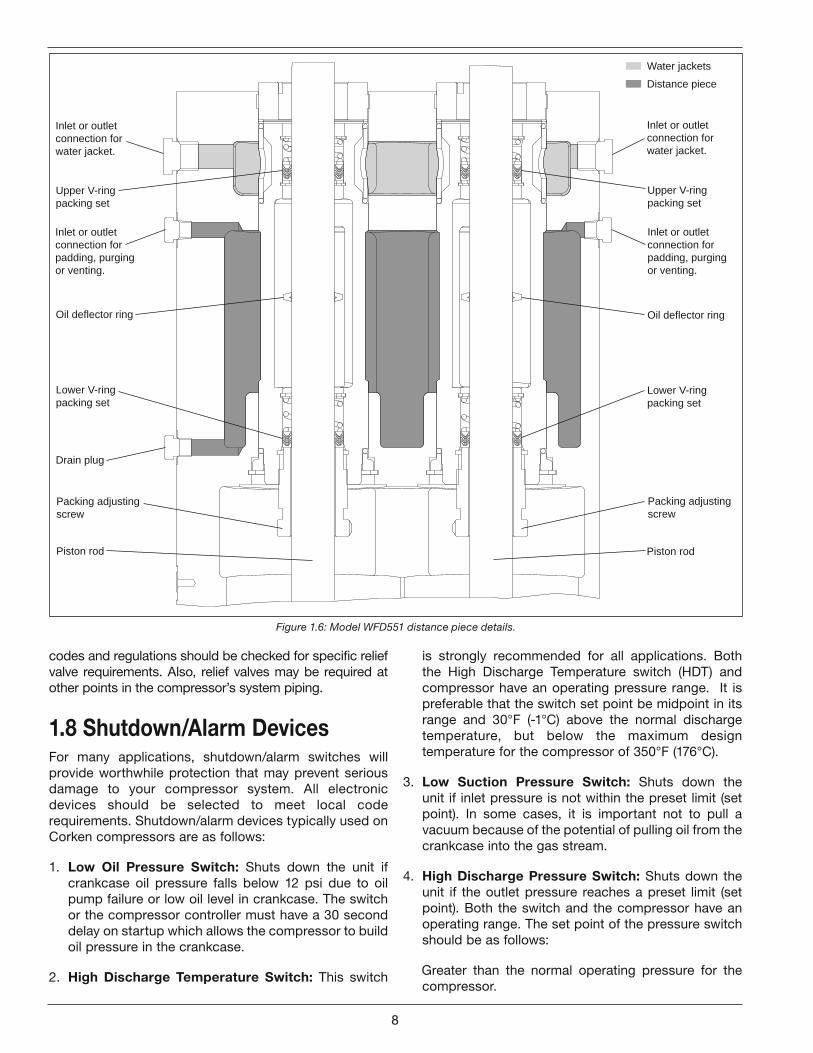
Inlet or outletconnection forpadding, purgingor venting.
Drain plug
Inlet or outlet connection forwater jacket.
Inlet or outletconnection forpadding, purgingor venting.
Inlet or outlet connection forwater jacket.
Water jackets
Distance piece
Upper V-ringpacking set
Lower V-ringpacking set
Upper V-ringpacking set
Lower V-ringpacking set
Oil deflector ring Oil deflector ring
Piston rod Piston rod
Packing adjustingscrew
Packing adjustingscrew
codes and regulations should be checked for specific relief valve requirements. Also, relief valves may be required at other points in the compressor’s system piping.
1.8 Shutdown/Alarm DevicesFor many applications, shutdown/alarm switches will provide worthwhile protection that may prevent serious damage to your compressor system. All electronic devices should be selected to meet local code requirements. Shutdown/alarm devices typically used on Corken compressors are as follows:
1. Low Oil Pressure Switch: Shuts down the unit if crankcase oil pressure falls below 12 psi due to oil pump failure or low oil level in crankcase. The switch or the compressor controller must have a 30 second delay on startup which allows the compressor to build oil pressure in the crankcase.
2. High Discharge Temperature Switch: This switch
Figure 1.6: Model WFD551 distance piece details.
is strongly recommended for all applications. Both the High Discharge Temperature switch (HDT) and compressor have an operating pressure range. It is preferable that the switch set point be midpoint in its range and 30°F (-1°C) above the normal discharge temperature, but below the maximum design temperature for the compressor of 350°F (176°C).
3. Low Suction Pressure Switch: Shuts down the unit if inlet pressure is not within the preset limit (set point). In some cases, it is important not to pull a vacuum because of the potential of pulling oil from the crankcase into the gas stream.
4. High Discharge Pressure Switch: Shuts down the unit if the outlet pressure reaches a preset limit (set point). Both the switch and the compressor have an operating range. The set point of the pressure switch should be as follows:
Greater than the normal operating pressure for the compressor.
8
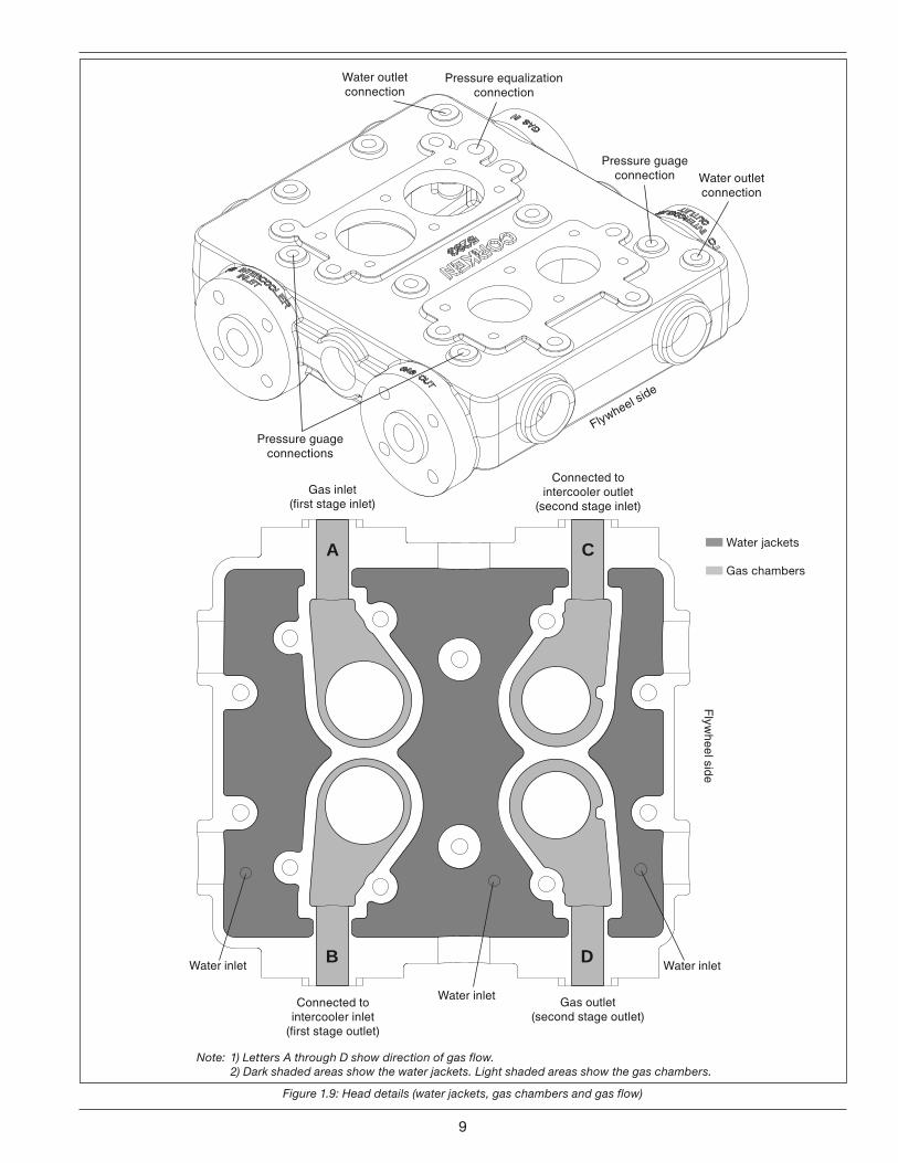
Flywheel side
Water outletconnection
Water outletconnection
Pressure equalizationconnection
Pressure guageconnection
Pressure guageconnections
Figure 1.9: Head details (water jackets, gas chambers and gas flow)
D
C
B
A
Flyw
heel side
Gas inlet(first stage inlet)
Connected tointercooler outlet
(second stage inlet)
Connected tointercooler inlet
(first stage outlet)
Gas outlet(second stage outlet)
Water inlet
Water inlet
Water inlet
Note: 1) Letters A through D show direction of gas flow.2) Dark shaded areas show the water jackets. Light shaded areas show the gas chambers.
Water jackets
Gas chambers
9
Less than 90% of the relief valve set point pressure.
Less than the maximum operating pressure of the compressor.
Midpoint of the pressure switch range.
5. Vibration Switch: Shuts down the unit if vibration becomes excessive. Recommended for units mounted to a portable skid.
1.9 Compressor CoolingThis compressor has a water-cooled head and cylinder. There is one water inlet connection on the cylinder and two water outlet connections on the head. The owner of the compressor is responsible for the inlet and outlet water connections.
The cylinder has one water jacket while the head has three water jackets. See Figure 1.9 for details.
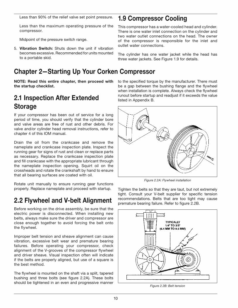
to the specified torque by the manufacturer. There must be a gap between the bushing flange and the flywheel when installation is complete. Always check the flywheel runout before startup and readjust if it exceeds the value listed in Appendix B.
Figure 2.2A: Flywheel installation
Tighten the belts so that they are taut, but not extremely tight. Consult your V-belt supplier for specific tension recommendations. Belts that are too tight may cause premature bearing failure. Refer to figure 2.2B.
Figure 2.2B: Belt tension
NOTE: Read this entire chapter, then proceed with the startup checklist.
2.1 Inspection After Extended StorageIf your compressor has been out of service for a long period of time, you should verify that the cylinder bore and valve areas are free of rust and other debris. For valve and/or cylinder head removal instructions, refer to chapter 4 of this IOM manual.
Drain the oil from the crankcase and remove the nameplate and crankcase inspection plate. Inspect the running gear for signs of rust and clean or replace parts as necessary. Replace the crankcase inspection plate and fill crankcase with the appropriate lubricant through the nameplate inspection opening. Squirt oil on the crossheads and rotate the crankshaft by hand to ensure that all bearing surfaces are coated with oil.
Rotate unit manually to ensure running gear functions properly. Replace nameplate and proceed with startup.
2.2 Flywheel and V-belt AlignmentBefore working on the drive assembly, be sure that the electric power is disconnected. When installing new belts, always make sure the driver and compressor are close enough together to avoid forcing the belt onto the flywheel.
Improper belt tension and sheave alignment can cause vibration, excessive belt wear and premature bearing failures. Before operating your compressor, check alignment of the V-grooves of the compressor flywheel and driver sheave. Visual inspection often will indicate if the belts are properly aligned, but use of a square is the best method.
The flywheel is mounted on the shaft via a split, tapered bushing and three bolts (see figure 2.2A). These bolts should be tightened in an even and progressive manner
Chapter 2—Starting Up Your Corken Compressor
10
2.3 Crankcase Oil Pressure AdjustmentYour Corken compressor is equipped with an automatically reversible gear type oil pump. It is essential to ensure the pumping system is primed and the oil pressure is properly adjusted in order to assure smooth operation.
WARNING
Before starting your compressor, check and fill the crankcase with the proper amount of lubricating oil.
When the compressor is first started, observe the crankcase oil pressure gauge. If the gauge fails to indicate pressure within 30 seconds, stop the machine. Loosen the oil filter and remove the pressure gauge. Restart the compressor and run it until oil comes out of the pressure gauge opening or around the filter. Tighten the filter and reinstall the pressure gauge.
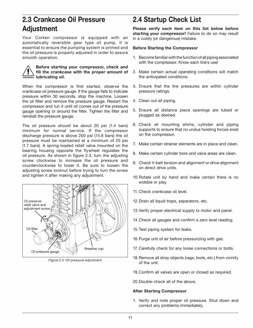
The oil pressure should be about 20 psi (1.4 bars) minimum for normal service. If the compressor discharge pressure is above 200 psi (14.8 bars) the oil pressure must be maintained at a minimum of 25 psi (1.7 bars). A spring-loaded relief valve mounted on the bearing housing opposite the flywheel regulates the oil pressure. As shown in figure 2.3, turn the adjusting screw clockwise to increase the oil pressure and counterclockwise to lower it. Be sure to loosen the adjusting screw locknut before trying to turn the screw and tighten it after making any adjustment.
Oil filter
Oil pressure gaugeBreather cap
Oil pressurerelief valve and adjustment screw
Figure 2.3: Oil pressure adjustment
2.4 Startup Check ListPlease verify each item on this list below before starting your compressor! Failure to do so may result in a costly (or dangerous) mistake.
Before Starting the Compressor
1. Become familiar with the function of all piping associated with the compressor. Know each line’s use!
2. Make certain actual operating conditions will match the anticipated conditions.
3. Ensure that the line pressures are within cylinder pressure ratings.
4. Clean out all piping.
5. Ensure all distance piece openings are tubed or plugged as desired.
6. Check all mounting shims, cylinder and piping supports to ensure that no undue twisting forces exist on the compressor.
7. Make certain strainer elements are in place and clean.
8. Make certain cylinder bore and valve areas are clean.
9. Check V-belt tension and alignment or drive alignment on direct drive units.
10. Rotate unit by hand and make certain there is no wobble or play.
11. Check crankcase oil level.
12. Drain all liquid traps, separators, etc.
13. Verify proper electrical supply to motor and panel.
14. Check all gauges and confirm a zero level reading.
15. Test piping system for leaks.
16. Purge unit of air before pressurizing with gas.
17. Carefully check for any loose connections or bolts.
18. Remove all stray objects (rags, tools, etc.) from vicinity of the unit.
19. Confirm all valves are open or closed as required.
20. Double-check all of the above.
After Starting Compressor
1. Verify and note proper oil pressure. Shut down and correct any problems immediately.
11
2. Observe noise and vibration levels. Correct immediately if excessive.
3. Verify proper compressor speed.
4. Examine entire system for gas or oil leaks.
5. Note rotation direction.
6. Check start-up voltage drop, running amperage and voltage at motor junction box (not at the starter).
7. Verify proper lubrication rate (lubed units only).
8. Test each shutdown device and record set points.
9. Test or confirm set point on all relief valves.
10. Check and record all temperatures, pressures and volumes after 30 minutes and 1 hour.
11. After 1 hour running time, tighten all head bolts, valve holddown bolts, and baseplate bolts. See Appendix B for torque values.
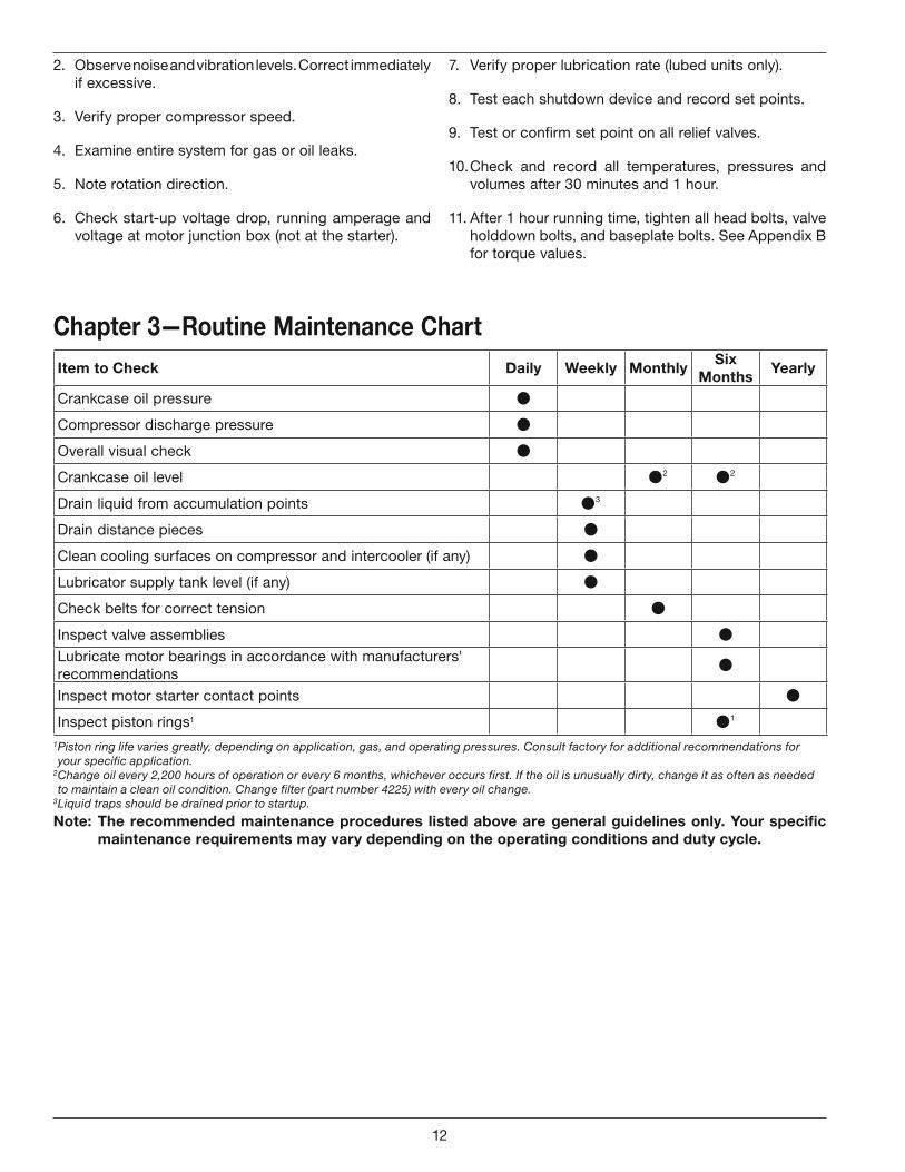
Item to Check Daily Weekly MonthlySix
MonthsYearly
Crankcase oil pressure
Compressor discharge pressure
Overall visual check
Crankcase oil level 2 2
Drain liquid from accumulation points 3
Drain distance pieces
Clean cooling surfaces on compressor and intercooler (if any)
Lubricator supply tank level (if any)
Check belts for correct tension
Inspect valve assemblies
Lubricate motor bearings in accordance with manufacturers' recommendations
Inspect motor starter contact points
Inspect piston rings1 1
1 Piston ring life varies greatly, depending on application, gas, and operating pressures. Consult factory for additional recommendations for your specific application.
2 Change oil every 2,200 hours of operation or every 6 months, whichever occurs first. If the oil is unusually dirty, change it as often as needed to maintain a clean oil condition. Change filter (part number 4225) with every oil change.
3 Liquid traps should be drained prior to startup.
Chapter 3—Routine Maintenance Chart
Note: The recommended maintenance procedures listed above are general guidelines only. Your specific maintenance requirements may vary depending on the operating conditions and duty cycle.
12
CAUTION: Always relieve pressure in the unit before attempting any repairs. After repair, the unit should be pressure tested and checked for leaks at all joints and gasket surfaces.
If routine maintenance is performed as listed in chapter 3, repair service on your Corken gas compressor is generally limited to replacing valves or piston rings. When it comes time to order replacement parts, be sure to consult the part details appendix in the back of this Installation, Operation & Maintenance (IOM) manual for a complete list of part numbers and descriptions.
4.1 ValvesTest the compressor valves by closing the inlet piping valves while the unit is running; however, do not allow the machine to operate in this way very long. If the inlet pressure gauge does not drop to zero almost immediately, one or more of the valves is probably damaged or dirty. However, it is possible for the pressure gauge itself to be faulty.
WARNING
In most cases, if a valve or gasket is leaking, it will create more heat.
Each suction and/or discharge valve assembly is easily removed as a unit for inspection. If any part of the valve assembly is broken, the valve assembly should be replaced. See valve assembly parts details in the Appendix E for a complete list of part numbers and descriptions.
If a valve is leaking due to dirt or any other foreign material that keeps the valve plate and seat from sealing, the valve may be cleaned and reused. New valve gaskets and O-rings should be used to assure a good seal.
The valve holddown assemblies and valve assemblies on the following pages show the various specifications used on this compressor. Since more than one suction valve arrangement is available for each model of compressor, it is necessary to know your complete model number so you can identify the valve type specification number (see example listed below).
Model number WFD551AM 4P FDAFSNN
Valve type = spec 4P
Valve Inspection and/or Replacement
Before removing and inspecting the valves, begin by depressurizing and purging (if necessary) the unit.
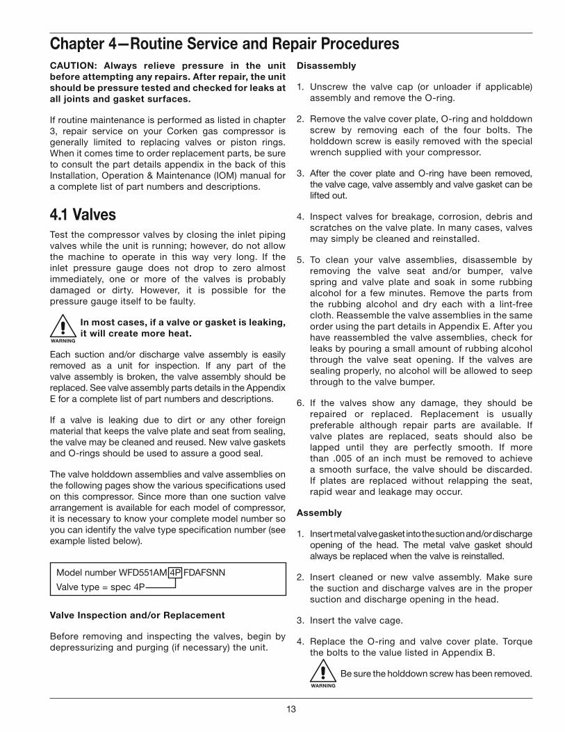
Chapter 4—Routine Service and Repair ProceduresDisassembly
1. Unscrew the valve cap (or unloader if applicable) assembly and remove the O-ring.
2. Remove the valve cover plate, O-ring and holddown screw by removing each of the four bolts. The holddown screw is easily removed with the special wrench supplied with your compressor.
3. After the cover plate and O-ring have been removed, the valve cage, valve assembly and valve gasket can be lifted out.
4. Inspect valves for breakage, corrosion, debris and scratches on the valve plate. In many cases, valves may simply be cleaned and reinstalled.
5. To clean your valve assemblies, disassemble by removing the valve seat and/or bumper, valve spring and valve plate and soak in some rubbing alcohol for a few minutes. Remove the parts from the rubbing alcohol and dry each with a lint-free cloth. Reassemble the valve assemblies in the same order using the part details in Appendix E. After you have reassembled the valve assemblies, check for leaks by pouring a small amount of rubbing alcohol through the valve seat opening. If the valves are sealing properly, no alcohol will be allowed to seep through to the valve bumper.
6. If the valves show any damage, they should be repaired or replaced. Replacement is usually preferable although repair parts are available. If valve plates are replaced, seats should also be lapped until they are perfectly smooth. If more than .005 of an inch must be removed to achieve a smooth surface, the valve should be discarded. If plates are replaced without relapping the seat, rapid wear and leakage may occur.
Assembly
1. Insert metal valve gasket into the suction and/or discharge opening of the head. The metal valve gasket should always be replaced when the valve is reinstalled.
2. Insert cleaned or new valve assembly. Make sure the suction and discharge valves are in the proper suction and discharge opening in the head.
3. Insert the valve cage.
4. Replace the O-ring and valve cover plate. Torque the bolts to the value listed in Appendix B.
WARNING
Be sure the holddown screw has been removed.
13
5. To ensure the valve gasket is properly seated, insert the holddown screw and tighten to the value listed in Appendix B.
WARNING
Gaskets and O-rings are not normally reusable.
6. Replace the O-ring and valve cap (or unloader assembly if applicable) and tighten to the value listed in Appendix B.
7. Check bolts and valve holddown screws after first week of operation. Re-torque if necessary. See Appendix B for torque values.
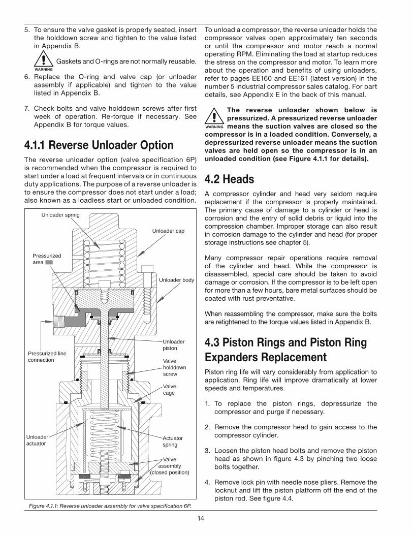
4.1.1 Reverse Unloader OptionThe reverse unloader option (valve specification 6P) is recommended when the compressor is required to start under a load at frequent intervals or in continuous duty applications. The purpose of a reverse unloader is to ensure the compressor does not start under a load; also known as a loadless start or unloaded condition.
To unload a compressor, the reverse unloader holds the compressor valves open approximately ten seconds or until the compressor and motor reach a normal operating RPM. Eliminating the load at startup reduces the stress on the compressor and motor. To learn more about the operation and benefits of using unloaders, refer to pages EE160 and EE161 (latest version) in the number 5 industrial compressor sales catalog. For part details, see Appendix E in the back of this manual.
WARNING
The reverse unloader shown below is pressurized. A pressurized reverse unloader means the suction valves are closed so the
compressor is in a loaded condition. Conversely, a depressurized reverse unloader means the suction valves are held open so the compressor is in an unloaded condition (see Figure 4.1.1 for details).
4.2 HeadsA compressor cylinder and head very seldom require replacement if the compressor is properly maintained. The primary cause of damage to a cylinder or head is corrosion and the entry of solid debris or liquid into the compression chamber. Improper storage can also result in corrosion damage to the cylinder and head (for proper storage instructions see chapter 5).
Many compressor repair operations require removal of the cylinder and head. While the compressor is disassembled, special care should be taken to avoid damage or corrosion. If the compressor is to be left open for more than a few hours, bare metal surfaces should be coated with rust preventative.
When reassembling the compressor, make sure the bolts are retightened to the torque values listed in Appendix B.
4.3 Piston Rings and Piston Ring Expanders ReplacementPiston ring life will vary considerably from application to application. Ring life will improve dramatically at lower speeds and temperatures.
1. To replace the piston rings, depressurize the compressor and purge if necessary.
2. Remove the compressor head to gain access to the compressor cylinder.
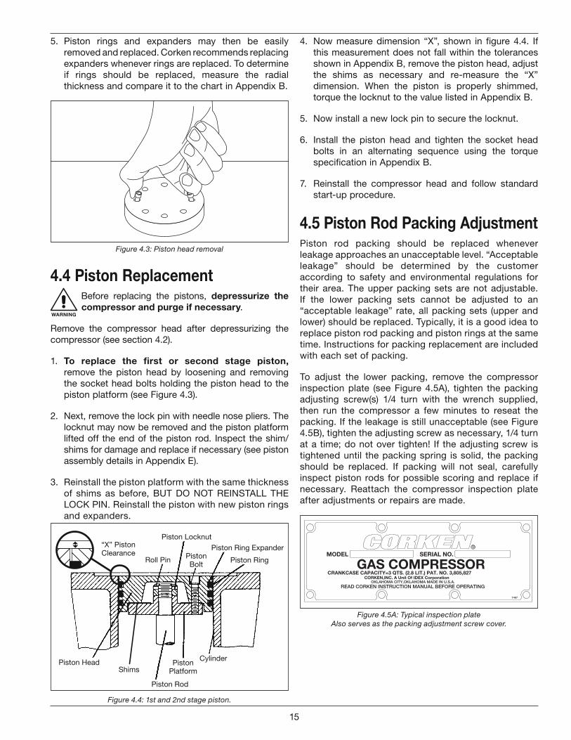
3. Loosen the piston head bolts and remove the piston head as shown in figure 4.3 by pinching two loose bolts together.
4. Remove lock pin with needle nose pliers. Remove the locknut and lift the piston platform off the end of the piston rod. See figure 4.4.
Figure 4.1.1: Reverse unloader assembly for valve specification 6P.
Unloader body
Unloader cap
Unloader spring
Unloaderpiston
Pressurized lineconnection
Actuatorspring
Unloaderactuator
Valveassembly
(closed position)
Valvecage
Valveholddownscrew
Pressurizedarea
14
4. Now measure dimension “X”, shown in figure 4.4. If this measurement does not fall within the tolerances shown in Appendix B, remove the piston head, adjust the shims as necessary and re-measure the “X” dimension. When the piston is properly shimmed, torque the locknut to the value listed in Appendix B.
5. Now install a new lock pin to secure the locknut.
6. Install the piston head and tighten the socket head bolts in an alternating sequence using the torque specification in Appendix B.
7. Reinstall the compressor head and follow standard start-up procedure.
4.5 Piston Rod Packing AdjustmentPiston rod packing should be replaced whenever leakage approaches an unacceptable level. “Acceptable leakage” should be determined by the customer according to safety and environmental regulations for their area. The upper packing sets are not adjustable. If the lower packing sets cannot be adjusted to an “acceptable leakage” rate, all packing sets (upper and lower) should be replaced. Typically, it is a good idea to replace piston rod packing and piston rings at the same time. Instructions for packing replacement are included with each set of packing.
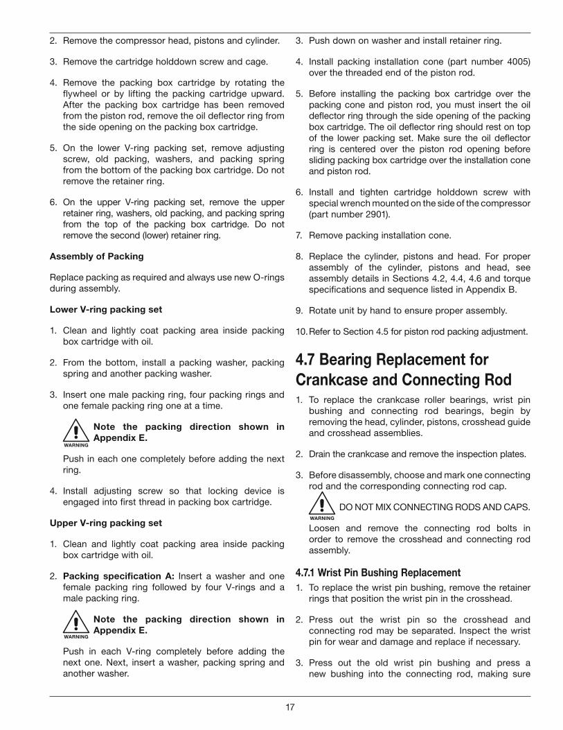
To adjust the lower packing, remove the compressor inspection plate (see Figure 4.5A), tighten the packing adjusting screw(s) 1/4 turn with the wrench supplied, then run the compressor a few minutes to reseat the packing. If the leakage is still unacceptable (see Figure 4.5B), tighten the adjusting screw as necessary, 1/4 turn at a time; do not over tighten! If the adjusting screw is tightened until the packing spring is solid, the packing should be replaced. If packing will not seal, carefully inspect piston rods for possible scoring and replace if necessary. Reattach the compressor inspection plate after adjustments or repairs are made.
Figure 4.5A: Typical inspection plate Also serves as the packing adjustment screw cover.
5. Piston rings and expanders may then be easily removed and replaced. Corken recommends replacing expanders whenever rings are replaced. To determine if rings should be replaced, measure the radial thickness and compare it to the chart in Appendix B.
Figure 4.3: Piston head removal
4.4 Piston Replacement
WARNING
Before replacing the pistons, depressurize the compressor and purge if necessary.
Remove the compressor head after depressurizing the compressor (see section 4.2).
1. To replace the first or second stage piston, remove the piston head by loosening and removing the socket head bolts holding the piston head to the piston platform (see Figure 4.3).
2. Next, remove the lock pin with needle nose pliers. The locknut may now be removed and the piston platform lifted off the end of the piston rod. Inspect the shim/shims for damage and replace if necessary (see piston assembly details in Appendix E).
3. Reinstall the piston platform with the same thickness of shims as before, BUT DO NOT REINSTALL THE LOCK PIN. Reinstall the piston with new piston rings and expanders.
“X” Piston Clearance
Piston HeadShims
Roll Pin Piston Bolt
Piston Locknut
Piston Ring Expander
Piston Ring
Piston Platform
Cylinder
Piston Rod
Figure 4.4: 1st and 2nd stage piston.
15
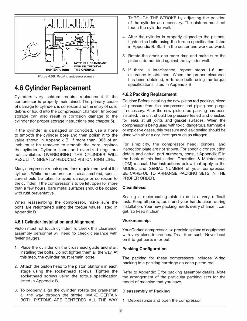
Figure 4.5B: Packing adjusting screws
4.6 Cylinder ReplacementCylinders very seldom require replacement if the compressor is properly maintained. The primary cause of damage to cylinders is corrosion and the entry of solid debris or liquid into the compression chamber. Improper storage can also result in corrosion damage to the cylinder (for proper storage instructions see chapter 5).
If the cylinder is damaged or corroded, use a hone to smooth the cylinder bore and then polish it to the value shown in Appendix B. If more than .005 of an inch must be removed to smooth the bore, replace the cylinder. Cylinder liners and oversized rings are not available. OVERBORING THE CYLINDER WILL RESULT IN GREATLY REDUCED PISTON RING LIFE.
Many compressor repair operations require removal of the cylinder. While the compressor is disassembled, special care should be taken to avoid damage or corrosion to the cylinder. If the compressor is to be left open for more than a few hours, bare metal surfaces should be coated with rust preventative.
When reassembling the compressor, make sure the bolts are retightened using the torque values listed in Appendix B.
4.6.1 Cylinder Installation and AlignmentPiston must not touch cylinder! To check this clearance, assembly personnel will need to check clearance with feeler gauges.
1. Place the cylinder on the crosshead guide and start installing the bolts. Do not tighten them all the way. At this step, the cylinder must remain loose.
2. Attach the piston head to the piston platform in each stage using the sockethead screws. Tighten the sockethead screws using the torque specification listed in Appendix B.
3. To properly align the cylinder, rotate the crankshaft all the way through the stroke. MAKE CERTAIN BOTH PISTONS ARE CENTERED ALL THE WAY
THROUGH THE STROKE by adjusting the position of the cylinder as necessary. The pistons must not touch the cylinder wall.
4. After the cylinder is properly aligned to the pistons, tighten the bolts using the torque specification listed in Appendix B. Start in the center and work outward.
5. Rotate the crank one more time and make sure the pistons do not bind against the cylinder wall.
6. If there is interference, repeat steps 1-6 until clearance is obtained. When the proper clearance has been obtained, re-torque bolts using the torque specifications listed in Appendix B.
4.6.2 Packing ReplacementCaution: Before installing the new piston rod packing, bleed all pressure from the compressor and piping and purge if necessary. After the new piston rod packing has been installed, the unit should be pressure tested and checked for leaks at all joints and gasket surfaces. When the compressor is being used with toxic, dangerous, flammable or explosive gases, this pressure and leak testing should be done with air or a dry, inert gas such as nitrogen.
For simplicity, the compressor head, pistons, and inspection plate are not shown. For specific construction details and actual part numbers, consult Appendix E in the back of this Installation, Operation & Maintenance (IOM) manual. Use instructions below that apply to the MODEL and SERIAL NUMBER of your compressor. BE CAREFUL TO ARRANGE PACKING SETS IN THE PROPER ORDER.
Cleanliness:
Sealing a reciprocating piston rod is a very difficult task. Keep all parts, tools and your hands clean during installation. Your new packing needs every chance it can get, so keep it clean.
Workmanship:
Your Corken compressor is a precision piece of equipment with very close tolerances. Treat it as such. Never beat on it to get parts in or out.
Packing Configuration
The packing for these compressors includes V-ring packing in a packing cartridge on each piston rod.
Refer to Appendix E for packing assembly details. Note the arrangement of the particular packing sets for the model of machine that you have.
Disassembly of Packing
1. Depressurize and open the compressor.
16
2. Remove the compressor head, pistons and cylinder.
3. Remove the cartridge holddown screw and cage.
4. Remove the packing box cartridge by rotating the flywheel or by lifting the packing cartridge upward. After the packing box cartridge has been removed from the piston rod, remove the oil deflector ring from the side opening on the packing box cartridge.
5. On the lower V-ring packing set, remove adjusting screw, old packing, washers, and packing spring from the bottom of the packing box cartridge. Do not remove the retainer ring.
6. On the upper V-ring packing set, remove the upper retainer ring, washers, old packing, and packing spring from the top of the packing box cartridge. Do not remove the second (lower) retainer ring.
Assembly of Packing
Replace packing as required and always use new O-rings during assembly.
Lower V-ring packing set
1. Clean and lightly coat packing area inside packing box cartridge with oil.
2. From the bottom, install a packing washer, packing spring and another packing washer.
3. Insert one male packing ring, four packing rings and one female packing ring one at a time.
WARNING
Note the packing direction shown in Appendix E.
Push in each one completely before adding the next ring.
4. Install adjusting screw so that locking device is engaged into first thread in packing box cartridge.
Upper V-ring packing set
1. Clean and lightly coat packing area inside packing box cartridge with oil.
2. Packing specification A: Insert a washer and one female packing ring followed by four V-rings and a male packing ring.
WARNING
Note the packing direction shown in Appendix E.
Push in each V-ring completely before adding the next one. Next, insert a washer, packing spring and another washer.
3. Push down on washer and install retainer ring.
4. Install packing installation cone (part number 4005) over the threaded end of the piston rod.
5. Before installing the packing box cartridge over the packing cone and piston rod, you must insert the oil deflector ring through the side opening of the packing box cartridge. The oil deflector ring should rest on top of the lower packing set. Make sure the oil deflector ring is centered over the piston rod opening before sliding packing box cartridge over the installation cone and piston rod.
6. Install and tighten cartridge holddown screw with special wrench mounted on the side of the compressor (part number 2901).
7. Remove packing installation cone.
8. Replace the cylinder, pistons and head. For proper assembly of the cylinder, pistons and head, see assembly details in Sections 4.2, 4.4, 4.6 and torque specifications and sequence listed in Appendix B.
9. Rotate unit by hand to ensure proper assembly.
10. Refer to Section 4.5 for piston rod packing adjustment.
4.7 Bearing Replacement for Crankcase and Connecting Rod1. To replace the crankcase roller bearings, wrist pin
bushing and connecting rod bearings, begin by removing the head, cylinder, pistons, crosshead guide and crosshead assemblies.
2. Drain the crankcase and remove the inspection plates.
3. Before disassembly, choose and mark one connecting rod and the corresponding connecting rod cap.
WARNING
DO NOT MIX CONNECTING RODS AND CAPS.
Loosen and remove the connecting rod bolts in order to remove the crosshead and connecting rod assembly.
4.7.1 Wrist Pin Bushing Replacement1. To replace the wrist pin bushing, remove the retainer
rings that position the wrist pin in the crosshead.
2. Press out the wrist pin so the crosshead and connecting rod may be separated. Inspect the wrist pin for wear and damage and replace if necessary.
3. Press out the old wrist pin bushing and press a new bushing into the connecting rod, making sure
17
the lubrication hole in the bushing matches the oil passage in the connecting rod.
WARNING
DO NOT MACHINE THE O.D. OR I.D. OF THE BUSHING BEFORE PRESSING INTO CONNECTING ROD.
4. If the holes in the wrist pin bushing and connecting rod do not align, drill out the bushing through the connecting rod lubricant passage with a long drill bit. Bore the wrist pin bushing I.D. as indicated in Appendix B, crosshead and connecting rod assembly details. Over boring the bushing can lead to premature failure of the wrist pin bushing.
5. Inspect the oil passage for debris and clean thoroughly before proceeding.
6. Press the wrist pin back into the crosshead and wrist pin bushing and reinstall retainer rings.
WARNING
The fit between the wrist pin and bushing is tighter than lubricated air compressors and combustion engines.
4.7.2 Replacing Connecting Rod BearingsConnecting rod bearings are the semicircular bearings in the large end of the connecting rods. Make sure the indentations in the connecting rod bearing and connecting rod line up when installing the new bearings. KEEP CONNECTING RODS AND CAPS TOGETHER, AND MAKE SURE THE ARROW AND/OR ALIGNMENT NOTCH ON CONNECTING ROD AND CAP ARE ALIGNED.
Before reinstalling the crosshead/connecting rod assembly, make sure the crankshaft throw and bearing surface are clean and lubricated. Tighten the connecting rod bolts to the torque values listed in Appendix B.
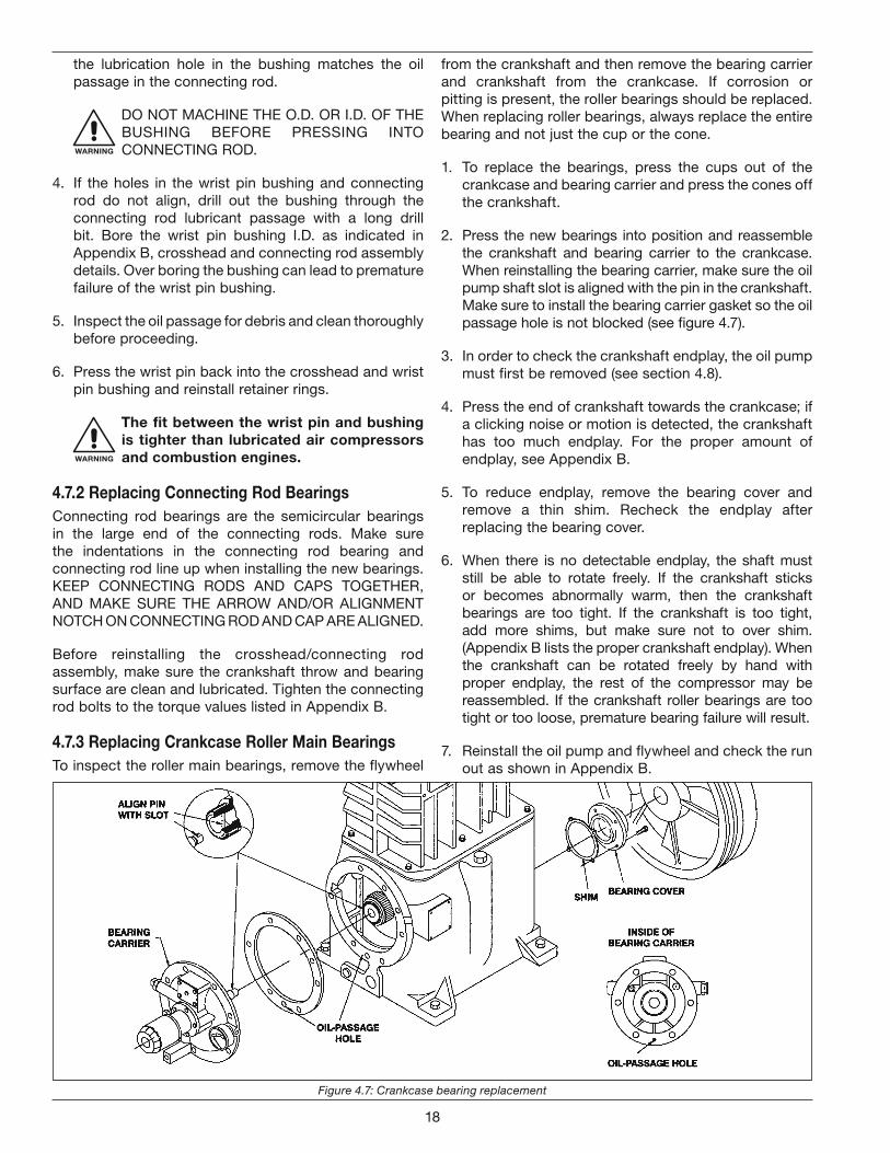
4.7.3 Replacing Crankcase Roller Main BearingsTo inspect the roller main bearings, remove the flywheel
from the crankshaft and then remove the bearing carrier and crankshaft from the crankcase. If corrosion or pitting is present, the roller bearings should be replaced. When replacing roller bearings, always replace the entire bearing and not just the cup or the cone.
1. To replace the bearings, press the cups out of the crankcase and bearing carrier and press the cones off the crankshaft.
2. Press the new bearings into position and reassemble the crankshaft and bearing carrier to the crankcase. When reinstalling the bearing carrier, make sure the oil pump shaft slot is aligned with the pin in the crankshaft. Make sure to install the bearing carrier gasket so the oil passage hole is not blocked (see figure 4.7).
3. In order to check the crankshaft endplay, the oil pump must first be removed (see section 4.8).
4. Press the end of crankshaft towards the crankcase; if a clicking noise or motion is detected, the crankshaft has too much endplay. For the proper amount of endplay, see Appendix B.
5. To reduce endplay, remove the bearing cover and remove a thin shim. Recheck the endplay after replacing the bearing cover.
6. When there is no detectable endplay, the shaft must still be able to rotate freely. If the crankshaft sticks or becomes abnormally warm, then the crankshaft bearings are too tight. If the crankshaft is too tight, add more shims, but make sure not to over shim. (Appendix B lists the proper crankshaft endplay). When the crankshaft can be rotated freely by hand with proper endplay, the rest of the compressor may be reassembled. If the crankshaft roller bearings are too tight or too loose, premature bearing failure will result.
7. Reinstall the oil pump and flywheel and check the run out as shown in Appendix B.
Figure 4.7: Crankcase bearing replacement
18
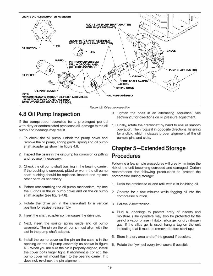
4.8 Oil Pump InspectionIf the compressor operates for a prolonged period with dirty or contaminated crankcase oil, damage to the oil pump and bearings may result.
1. To check the oil pump, unbolt the pump cover and remove the oil pump, spring guide, spring and oil pump shaft adapter as shown in figure 4.8.
2. Inspect the gears in the oil pump for corrosion or pitting and replace if necessary.
3. Check the oil pump shaft bushing in the bearing carrier. If the bushing is corroded, pitted or worn, the oil pump shaft bushing should be replaced. Inspect and replace other parts as necessary.
4. Before reassembling the oil pump mechanism, replace the O-rings in the oil pump cover and on the oil pump shaft adapter (see figure 4.8).
5. Rotate the drive pin in the crankshaft to a vertical position for easiest reassembly.
6. Insert the shaft adapter so it engages the drive pin.
7. Next, insert the spring, spring guide and oil pump assembly. The pin on the oil pump must align with the slot in the pump shaft adapter.
8. Install the pump cover so the pin on the case is in the opening on the oil pump assembly as shown in figure 4.8. When you are sure the pin is properly aligned, install the cover bolts finger tight. If alignment is correct, the pump cover will mount flush to the bearing carrier. If it does not, re-check the pin alignment.
9. Tighten the bolts in an alternating sequence. See section 2.3 for directions on oil pressure adjustment.
10. Finally, rotate the crankshaft by hand to ensure smooth operation. Then rotate it in opposite directions, listening for a click, which indicates proper alignment of the oil pump’s pins and slots.
Chapter 5—Extended Storage ProceduresFollowing a few simple procedures will greatly minimize the risk of the unit becoming corroded and damaged. Corken recommends the following precautions to protect the compressor during storage:
1. Drain the crankcase oil and refill with rust inhibiting oil.
2. Operate for a few minutes while fogging oil into the compressor suction.
3. Relieve V-belt tension.
4. Plug all openings to prevent entry of insects and moisture. (The cylinders may also be protected by the use of a vapor phase inhibitor, silica gel, or dry nitrogen gas. If the silica gel is used, hang a tag on the unit indicating that it must be removed before start-up.)
5. Store in a dry area and off the ground if possible.
6. Rotate the flywheel every two weeks if possible.
Figure 4.8: Oil pump inspection
19
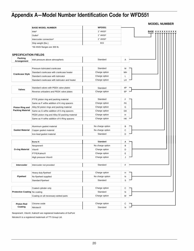
Appendix A—Model Number Identification Code for WFD551MODEL NUMBER
BASE MODEL NUMBER
Inlet* BASE X X X X X X X X X X
Outlet*
Intercooler connection*
Ship weight (lbs.)
*All ANSI flanges are 300 lb.
SPECIFICATION FIELDSPacking
ArrangementInlet pressure above atmospheric A
Pressure lubricated crankcase M
Standard crankcase with crankcase heater MH
Standard crankcase with lubricator L
Standard crankcase with lubricator and heater LH
Standard valves with PEEK valve plates 4P
Reverse unloaders and PEEK valve plates 6P
PTFE piston ring and packing material F
Same as F w/the addition of K-ring spacers FK
Alloy 50 piston rings and packing material G
Same as G w/the addition of K-ring spacers GK
PEEK piston ring and Alloy 50 packing material H
Same as H w/the addition of K-Ring spacers HK
Aluminum gasket material B
Copper gasket material C
Iron-lead gasket material D
Buna N A
Charge option
Charge option
No charge option
Standard
Charge option
Charge option
Charge option
Charge option
Charge option
Standard
No charge option
Standard
Charge option
Standard
Valves
Gasket Material
Standard
Charge option
Piston Ring and Packing Material
Standard
WFD551
1" ANSI*
1" ANSI*
1" ANSI*
815
Crankcase Style
Buna-N A
Neoprene® B
Viton® D
PTFE/Kalrez® E
High pressure Viton® J
Intercooler Intercooler not provided F
Heavy duty flywheel H
No flywheel supplied N
Standard flywheel S
Coated cylinder only C
No coating N
Coating on all necessary wetted parts W
Chrome oxide C
Nitrotec® N
Neoprene®, Viton®, Kalrez® are registered trademarks of DuPont
Nitrotec® is a registered trademark of TTI Group Ltd.
Charge optionPiston Rod Coating
Charge option
Charge option
Charge option
Charge option
Charge option
Charge option
Standard
Standard
Protective Coating Standard
Standard
No charge option
No charge optionFlywheel
O-ring Material
Standard
20
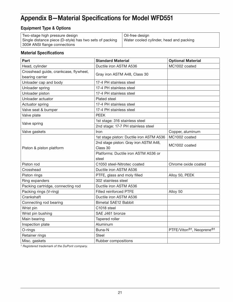
Appendix B—Material Specifications for Model WFD551
Part Standard Material Optional MaterialHead, cylinder Ductile iron ASTM A536 MC1002 coatedCrosshead guide, crankcase, flywheel, bearing carrier
Gray iron ASTM A48, Class 30
Unloader cap and body 17-4 PH stainless steelUnloader spring 17-4 PH stainless steelUnloader piston 17-4 PH stainless steelUnloader actuator Plated steelActuator spring 17-4 PH stainless steelValve seat & bumper 17-4 PH stainless steel Valve plate PEEK
Valve spring1st stage: 316 stainless steel2nd stage: 17-7 PH stainless steel
Valve gaskets Iron Copper, aluminum
Piston & piston platform
1st stage piston: Ductile iron ASTM A536 MC1002 coated2nd stage piston: Gray iron ASTM A48, Class 30
MC1002 coated
Platforms: Ductile iron ASTM A536 or steel
Piston rod C1050 steel-Nitrotec coated Chrome oxide coatedCrosshead Ductile iron ASTM A536Piston rings PTFE, glass and moly filled Alloy 50, PEEKRing expanders 302 stainless steelPacking cartridge, connecting rod Ductile iron ASTM A536Packing rings (V-ring) Filled reinforced PTFE Alloy 50Crankshaft Ductile iron ASTM A536Connecting rod bearing Bimetal SAE12 BabbitWrist pin C1018 steelWrist pin bushing SAE J461 bronzeMain bearing Tapered rollerInspection plate AluminumO-rings Buna-N PTFE/Viton®1, Neoprene®1
Retainer rings SteelMisc. gaskets Rubber compositions
1 Registered trademark of the DuPont company.
Equipment Type & Options
Two-stage high pressure designSingle distance piece (D-style) has two sets of packing300# ANSI flange connections
Oil-free designWater cooled cylinder, head and packing
Material Specifications
21
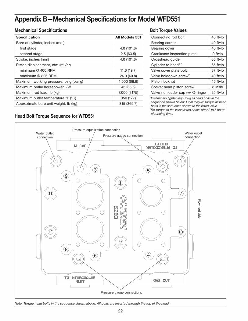
Appendix B—Mechanical Specifications for Model WFD551Mechanical Specifications Bolt Torque Values
Head Bolt Torque Sequence for WFD551
1
2
3
4
5
6
7
8
9
10
11
12
Flywheel side
Water outletconnection
Water outletconnectionPressure gauge connection
Pressure gauge connections
Pressure equalization connection
Note: Torque head bolts in the sequence shown above. All bolts are inserted through the top of the head.
Specification All Models 551
Bore of cylinder, inches (mm)
first stage 4.0 (101.6)
second stage 2.5 (63.5)
Stroke, inches (mm) 4.0 (101.6)
Piston displacement, cfm (m3/hr)
minimum @ 400 RPM 11.6 (19.7)
maximum @ 825 RPM 24.0 (40.8)
Maximum working pressure, psig (bar g) 1,000 (68.9)
Maximum brake horsepower, kW 45 (33.6)
Maximum rod load, lb (kg) 7,000 (3175)
Maximum outlet temperature °F (°C) 350 (177)
Approximate bare unit weight, lb (kg) 815 (369.7)
Connecting rod bolt 40 ft•lb
Bearing carrier 40 ft•lb
Bearing cover 40 ft•lb
Crankcase inspection plate 9 ft•lb
Crosshead guide 65 ft•lb
Cylinder to head1,2 65 ft•lb
Valve cover plate bolt 37 ft•lb
Valve holddown screw2 40 ft•lb
Piston locknut 45 ft•lb
Socket head piston screw 8 in•lb
Valve / unloader cap (w/ O-rings) 25 ft•lb1 Preliminary tightening: Snug all head bolts in the sequence shown below. Final torque: Torque all head bolts in the sequence shown to the listed value.
2 Re-torque to the value listed above after 2 to 5 hours of running time.
22
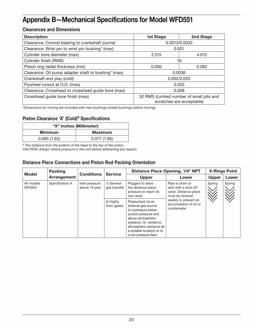
Appendix B—Mechanical Specifications for Model WFD551Clearances and Dimensions
Distance Piece Connections and Piston Rod Packing Orientation
*Dimensions for honing are included with new bushings (install bushings before honing).
Piston Clearance ‘X’ (Cold)a Specifications“X” Inches (Millimeter)
Minimum Maximum
0.065 (1.65) 0.077 (1.95)a The distance from the bottom of the head to the top of the piston.CAUTION: Always relieve pressure in the unit before attempting any repairs.
ModelPacking Arrangement
Conditions ServiceDistance Piece Opening, 1/4" NPT V-Rings Point
Upper Lower Upper LowerAll models WFD551
Specification A Inlet pressure: above 15 psia
1) General gas transfer
Plugged to allow the distance piece pressure to reach its own level.
Pipe to drain or vent with a shut-off valve. Distance piece must be drained weekly to prevent an accumulation of oil or condensate.
Spring Spring
2) Highly toxic gases
Pressurized via an external gas source to a pressure below suction pressure and above atmospheric pressure. Or, vented to atmospheric pressure (at a suitable location) or to a low pressure flare.
Description 1st Stage 2nd StageClearance: Conrod bearing to crankshaft journal 0.0013/0.0033Clearance: Wrist pin to wrist pin bushing* (max) 0.001Cylinder bore diameter (max) 2.515 4.015Cylinder finish (RMS) 16Piston ring radial thickness (min) 0.090 0.082Clearance: Oil pump adapter shaft to bushing* (max) 0.0036Crankshaft end play (cold) 0.002/0.003Flywheel runout at O.D. (max) 0.020Clearance: Crosshead to crosshead guide bore (max) 0.008Crosshead guide bore finish (max) 32 RMS (Limited number of small pits and
scratches are acceptable)
23
Inches (Centim
eters)
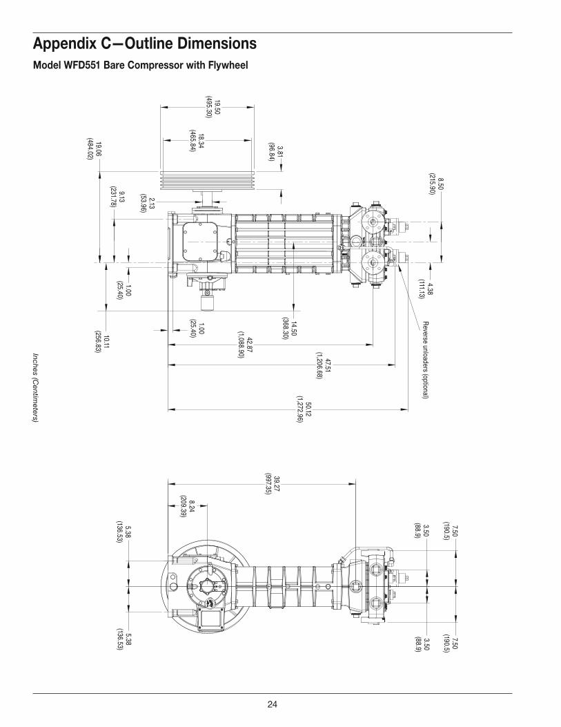
Appendix C—Outline DimensionsModel WFD551 Bare Compressor with Flywheel
3.81(96.84)
19.50(495.30)
18.34(465.84)
8.50(215.90)
4.38(111.13)
47.51(1,206.68)
42.87(1,088.90)
2.13(53.96)
1.00(25.40)
19.06(484.02)
1.00(25.40)
9.13(231.78)
10.11(256.83)
5.38(136.53)
8.24(209.39)
39.27(997.35)
3.50(88.9)
7.50(190.5)
7.50(190.5)
50.12(1,272.96)
Reverse unloaders (optional)
3.50(88.9)
5.38(136.53)
14.50(368.30)
24
Inches (Centim
eters)
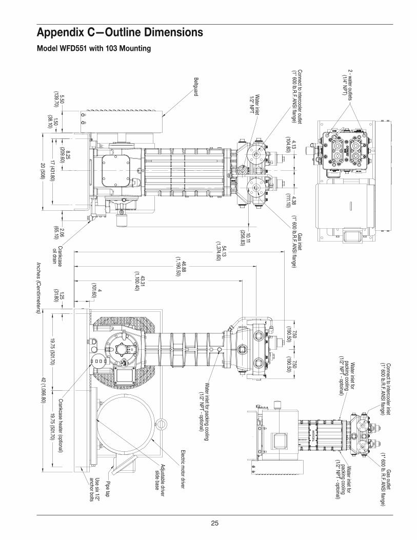
Appendix C—Outline DimensionsModel WFD551 with 103 Mounting
19.75 (501.70)
1.25(31.80)
42 (1,066.80)
43.31(1,100.40)4
(101.60)
46.88(1,190.50)
54.13(1,374.60)
7.50(190.50)
4.13(104.80)
4.38(111.10)
1.50(38.10)
8.25(209.60)17 (431.80)
5.50(139.70)
20 (508)
2.06(65.10)
10.11(256.83)
Water inlet for packing cooling
(1/2" NPT - optional)
Use six 1/2"anchor bolts
Electric motor driver
Pipe tap
Adjustable driverslide base
Crankcase heater (optional)
Gas inlet
(1" 600 lb.R.F. ANSI flange)Connect to intercooler outlet(1" 600 lb.R.F. ANSI flange)
Water inlet
1/2" NPT
Beltguard
Crankcaseoil drain
2 - water outlets(1/4" NPT)
Water inlet for
packing cooling(1/2" NPT - optoinal)
Gas outlet
(1" 600 lb. R.F. ANSI flange)Connect to intercooler inlet(1" 600 lb.R.F. ANSI flange)
7.50(190.50)
19.75 (501.70)
Water inlet for
packing cooling(1/2" NPT - optoinal)
25
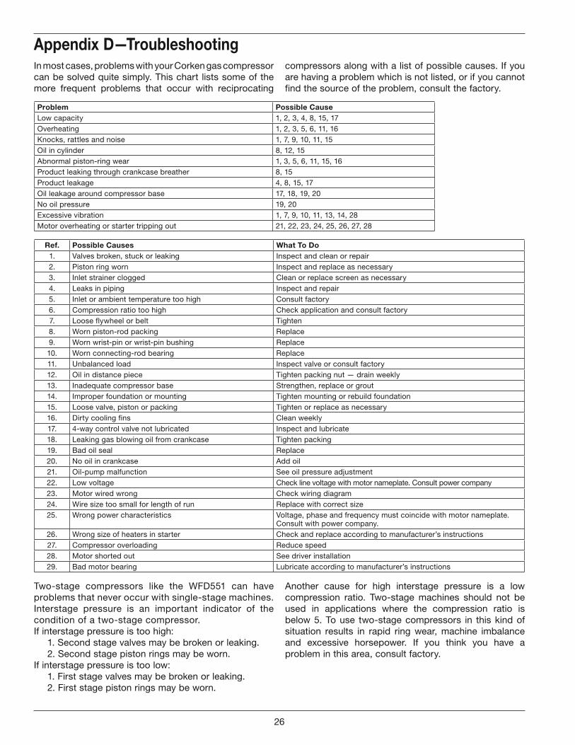
Two-stage compressors like the WFD551 can have problems that never occur with single-stage machines. Interstage pressure is an important indicator of the condition of a two-stage compressor.If interstage pressure is too high: 1. Second stage valves may be broken or leaking. 2. Second stage piston rings may be worn.If interstage pressure is too low: 1. First stage valves may be broken or leaking. 2. First stage piston rings may be worn.
In most cases, problems with your Corken gas compressor can be solved quite simply. This chart lists some of the more frequent problems that occur with reciprocating
compressors along with a list of possible causes. If you are having a problem which is not listed, or if you cannot find the source of the problem, consult the factory.
Appendix D—Troubleshooting
Problem Possible CauseLow capacity 1, 2, 3, 4, 8, 15, 17Overheating 1, 2, 3, 5, 6, 11, 16Knocks, rattles and noise 1, 7, 9, 10, 11, 15Oil in cylinder 8, 12, 15Abnormal piston-ring wear 1, 3, 5, 6, 11, 15, 16Product leaking through crankcase breather 8, 15Product leakage 4, 8, 15, 17Oil leakage around compressor base 17, 18, 19, 20No oil pressure 19, 20Excessive vibration 1, 7, 9, 10, 11, 13, 14, 28Motor overheating or starter tripping out 21, 22, 23, 24, 25, 26, 27, 28
Ref. Possible Causes What To Do1. Valves broken, stuck or leaking Inspect and clean or repair2. Piston ring worn Inspect and replace as necessary3. Inlet strainer clogged Clean or replace screen as necessary4. Leaks in piping Inspect and repair5. Inlet or ambient temperature too high Consult factory6. Compression ratio too high Check application and consult factory7. Loose flywheel or belt Tighten8. Worn piston-rod packing Replace9. Worn wrist-pin or wrist-pin bushing Replace10. Worn connecting-rod bearing Replace11. Unbalanced load Inspect valve or consult factory12. Oil in distance piece Tighten packing nut — drain weekly13. Inadequate compressor base Strengthen, replace or grout14. Improper foundation or mounting Tighten mounting or rebuild foundation15. Loose valve, piston or packing Tighten or replace as necessary16. Dirty cooling fins Clean weekly17. 4-way control valve not lubricated Inspect and lubricate18. Leaking gas blowing oil from crankcase Tighten packing19. Bad oil seal Replace20. No oil in crankcase Add oil21. Oil-pump malfunction See oil pressure adjustment22. Low voltage Check line voltage with motor nameplate. Consult power company23. Motor wired wrong Check wiring diagram24. Wire size too small for length of run Replace with correct size25. Wrong power characteristics Voltage, phase and frequency must coincide with motor nameplate.
Consult with power company.26. Wrong size of heaters in starter Check and replace according to manufacturer’s instructions27. Compressor overloading Reduce speed28. Motor shorted out See driver installation29. Bad motor bearing Lubricate according to manufacturer’s instructions
Another cause for high interstage pressure is a low compression ratio. Two-stage machines should not be used in applications where the compression ratio is below 5. To use two-stage compressors in this kind of situation results in rapid ring wear, machine imbalance and excessive horsepower. If you think you have a problem in this area, consult factory.
26
Water outletconnection
Water outletconnection
1
2
3
4
6
6
7
6
5
78
10
9(connects tubing to the bottom of the cylinder)
6 6
6
7
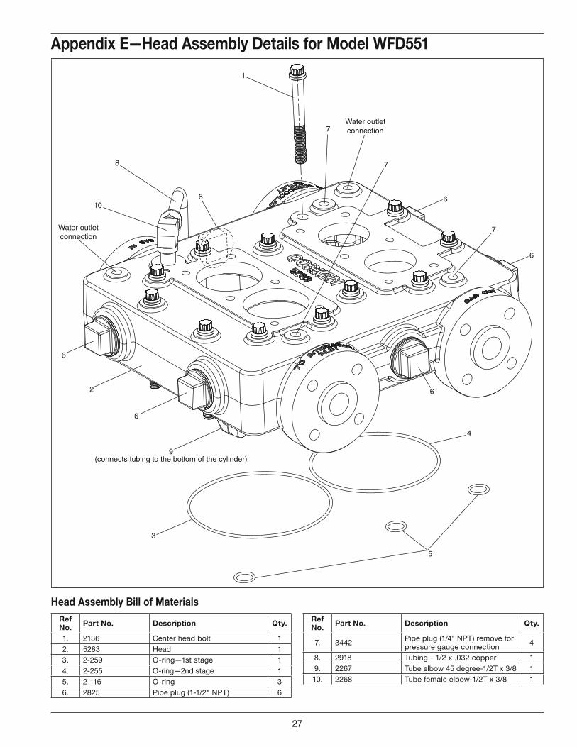
Appendix E—Head Assembly Details for Model WFD551
Ref No. Part No. Description Qty.
1. 2136 Center head bolt 12. 5283 Head 13. 2-259 O-ring—1st stage 14. 2-255 O-ring—2nd stage 15. 2-116 O-ring 36. 2825 Pipe plug (1-1/2" NPT) 6
Head Assembly Bill of MaterialsRef No. Part No. Description Qty.
7. 3442 Pipe plug (1/4" NPT) remove for pressure gauge connection 4
8. 2918 Tubing - 1/2 x .032 copper 19. 2267 Tube elbow 45 degree-1/2T x 3/8 110. 2268 Tube female elbow-1/2T x 3/8 1
27
1st Stage Suction(Specification 6P—Reverse Unloader)
1st Stage Suction(Specification 4P—Standard)
1st Stage Discharge(All Specifications)
1
2
3
4
56 Spring down
7
89
10
11
10121314 15
16
17
18
19
20
21
22
24
1415
16
17
23
18
19
22
23 23
25
19
24
14
16
18
15
Spring down
Spring up
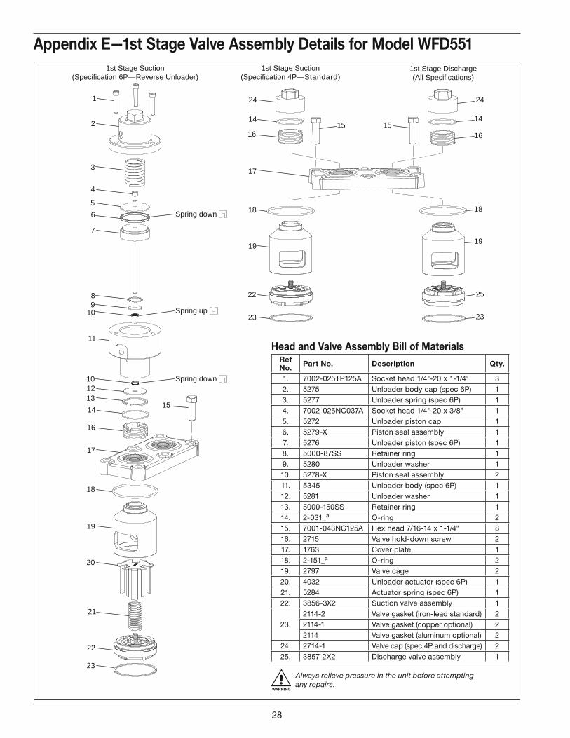
Appendix E—1st Stage Valve Assembly Details for Model WFD551
Ref No. Part No. Description Qty.
1. 7002-025TP125A Socket head 1/4"-20 x 1-1/4" 32. 5275 Unloader body cap (spec 6P) 13. 5277 Unloader spring (spec 6P) 14. 7002-025NC037A Socket head 1/4"-20 x 3/8" 15. 5272 Unloader piston cap 16. 5279-X Piston seal assembly 17. 5276 Unloader piston (spec 6P) 18. 5000-87SS Retainer ring 19. 5280 Unloader washer 110. 5278-X Piston seal assembly 211. 5345 Unloader body (spec 6P) 112. 5281 Unloader washer 113. 5000-150SS Retainer ring 114. 2-031_a O-ring 215. 7001-043NC125A Hex head 7/16-14 x 1-1/4" 816. 2715 Valve hold-down screw 217. 1763 Cover plate 118. 2-151_a O-ring 219. 2797 Valve cage 220. 4032 Unloader actuator (spec 6P) 121. 5284 Actuator spring (spec 6P) 122. 3856-3X2 Suction valve assembly 1
23.2114-2 Valve gasket (iron-lead standard) 22114-1 Valve gasket (copper optional) 22114 Valve gasket (aluminum optional) 2
24. 2714-1 Valve cap (spec 4P and discharge) 225. 3857-2X2 Discharge valve assembly 1
Head and Valve Assembly Bill of Materials
WARNING
Always relieve pressure in the unit before attemptingany repairs.
28
2nd Stage Suction(Specification 6P—Reverse Unloader)
2nd Stage Suction(Specification 4P—Standard)
2nd Stage Discharge(All Specifications)
1
2
3
4
56
7
89
10
11
10121314
16
17
18
19
20
21
22
23
24
14
16
17
18
19
22
23 23
25
19
24
14
16
18
15
15 15
Spring down
Spring down
Spring up
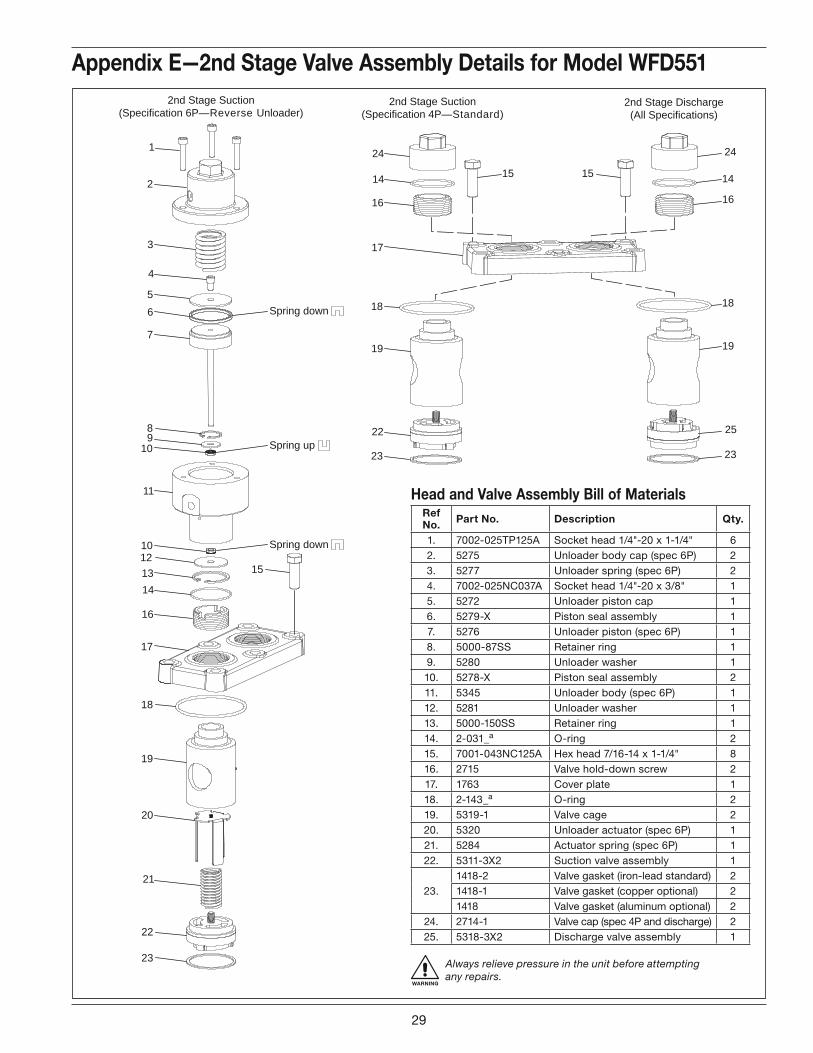
WARNING
Always relieve pressure in the unit before attemptingany repairs.
Appendix E—2nd Stage Valve Assembly Details for Model WFD551
Ref No. Part No. Description Qty.
1. 7002-025TP125A Socket head 1/4"-20 x 1-1/4" 62. 5275 Unloader body cap (spec 6P) 23. 5277 Unloader spring (spec 6P) 24. 7002-025NC037A Socket head 1/4"-20 x 3/8" 15. 5272 Unloader piston cap 16. 5279-X Piston seal assembly 17. 5276 Unloader piston (spec 6P) 18. 5000-87SS Retainer ring 19. 5280 Unloader washer 110. 5278-X Piston seal assembly 211. 5345 Unloader body (spec 6P) 112. 5281 Unloader washer 113. 5000-150SS Retainer ring 114. 2-031_a O-ring 215. 7001-043NC125A Hex head 7/16-14 x 1-1/4" 816. 2715 Valve hold-down screw 217. 1763 Cover plate 118. 2-143_a O-ring 219. 5319-1 Valve cage 220. 5320 Unloader actuator (spec 6P) 121. 5284 Actuator spring (spec 6P) 122. 5311-3X2 Suction valve assembly 1
23.1418-2 Valve gasket (iron-lead standard) 21418-1 Valve gasket (copper optional) 21418 Valve gasket (aluminum optional) 2
24. 2714-1 Valve cap (spec 4P and discharge) 225. 5318-3X2 Discharge valve assembly 1
Head and Valve Assembly Bill of Materials
29
2
3a 3a
4
5
1
6
7
2
7
4
5
6
8
2
3
4
5
6
7
8
9
8
7
6
5
4
3
2
9
1 10
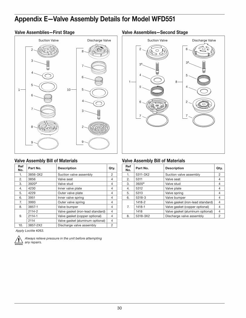
Valve Assemblies—Second StageValve Assemblies—First Stage
Appendix E—Valve Assembly Details for Model WFD551
Ref No. Part No. Description Qty.
1. 5311-3X2 Suction valve assembly 22. 5311 Valve seat 43. 3920a Valve stud 44. 5312 Valve plate 45. 5313 Valve spring 46. 5318-3 Valve bumper 4
7.1418-2 Valve gasket (iron-lead standard) 41418-1 Valve gasket (copper optional) 41418 Valve gasket (aluminum optional) 4
8. 5318-3X2 Discharge valve assembly 2
Ref No. Part No. Description Qty.
1. 3856-3X2 Suction valve assembly 22. 3856 Valve seat 43. 3920a Valve stud 44. 4230 Inner valve plate 45. 4229 Outer valve plate 46. 3951 Inner valve spring 47. 3993 Outer valve spring 48. 3857-1 Valve bumper 4
9.2114-2 Valve gasket (iron-lead standard) 42114-1 Valve gasket (copper optional) 42114 Valve gasket (aluminum optional) 4
10. 3857-2X2 Discharge valve assembly 2
Valve Assembly Bill of MaterialsValve Assembly Bill of Materials
Apply Loctite #263.
WARNING
Always relieve pressure in the unit before attemptingany repairs.
Suction ValveSuction Valve Discharge ValveDischarge Valve
30
1
2
3
4
56
7
8
Piston rod
1
2
3
4
5
6
7
8
Piston rod
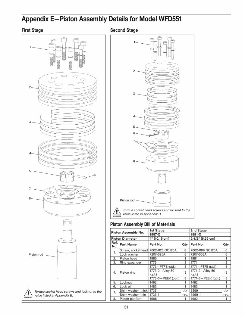
Piston Assembly No.1st Stage 2nd Stage1987-X 1981-X
Piston Diameter 4" (10.16 cm) 2-1/2" (6.35 cm)Ref. No. Part Name Part No. Qty. Part No. Qty.
1.Screw, sockethead 7002-025 OC125A 8 7002-008 NC125A 6Lock washer 7207-025A 8 7207-008A 6
2. Piston head 1985 1 1981 13. Ring expander 1776 3 1774 3
4. Piston ring
1773—PTFE (std.) 3 1771—PTFE (std.) 31773-2—Alloy 50 (opt.) 3 1771-2—Alloy 50
(opt.) 3
1773-3—PEEK (opt.) 3 1771-3—PEEK (opt.) 35. Locknut 1482 1 1482 16. Lock pin 1483 1 1483 1
7.Shim washer, thick 1735 As
req.6599 As
req.Shim washer, thin 1735-1 6599-18. Piston platform 1986 1 1982 1
First Stage Second Stage
Appendix E—Piston Assembly Details for Model WFD551
Piston Assembly Bill of Materials
WARNING
Torque socket head screws and locknut to the value listed in Appendix B.
WARNING
Torque socket head screws and locknut to the value listed in Appendix B.
31
1
2
3
7
6
3
8
5
4
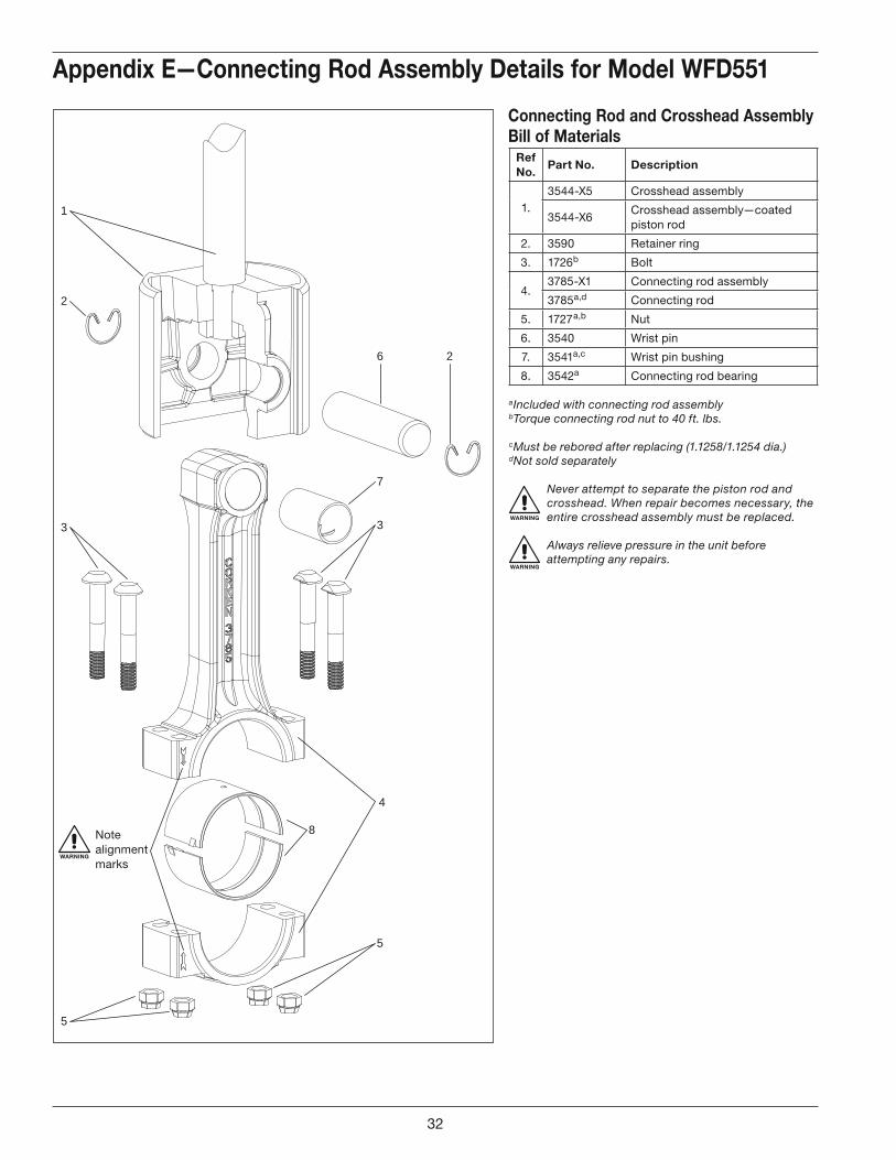
5
2
Appendix E—Connecting Rod Assembly Details for Model WFD551
Ref No.
Part No. Description
1.3544-X5 Crosshead assembly
3544-X6Crosshead assembly—coated piston rod
2. 3590 Retainer ring
3. 1726b Bolt
4.3785-X1 Connecting rod assembly
3785a,d Connecting rod
5. 1727a,b Nut
6. 3540 Wrist pin
7. 3541a,c Wrist pin bushing
8. 3542a Connecting rod bearing
Connecting Rod and Crosshead Assembly Bill of Materials
a Included with connecting rod assemblyb Torque connecting rod nut to 40 ft. lbs.
c Must be rebored after replacing (1.1258/1.1254 dia.)d Not sold separately
WARNING
Never attempt to separate the piston rod and crosshead. When repair becomes necessary, the entire crosshead assembly must be replaced.
WARNING
Always relieve pressure in the unit before attempting any repairs.
WARNING
Note alignment marks
32
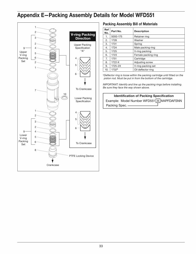
V-ring PackingDirection
Upper PackingSpecification
“A”
4
5
6
To Crankcase
Crankcase
4
5
6
To Crankcase
Lower PackingSpecification
2
5
3
6
7
10
2
8
2
3
1
4
5
9
6
4
2
1
1
2
LowerV-ring
PackingSet
9
UpperV-ring
PackingSet
PTFE Locking Device
Appendix E—Packing Assembly Details for Model WFD551Packing Assembly Bill of Materials
Ref No.
Part No. Description
1. 5000-175 Retainer ring2. 1728 Washer3. 1731 Spring4. 1724 Male packing ring5. 1725 V-ring packing6. 1723 Female packing ring7. 1751 Cartridge8. 1722-X Adjusting screw9. 1725-2X V-ring packing set10. 1732a Oil defl ector ring
Identification of Packing Specification
Example: Model Number WFD551 A M4PFDAFSNN Packing Spec.
a Deflector ring is loose within the packing cartridge until fitted on the piston rod. Must be put in from the bottom of the cartridge.
IMPORTANT: Identify and line up the packing rings before installing. Be sure they face the way shown above.
33
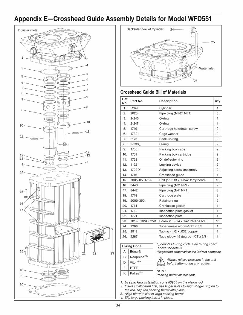
1
2 (water inlet)
3
5
6
78
9
8
10
11
8
1312
14
15
16
17
18
19
20
4
2
5
6
78
9
8
10
11
8
1312
2115 22 23
24
25
Water inlet
26
Backside View of Cylinder
Appendix E—Crosshead Guide Assembly Details for Model WFD551
O-ring Code
A Buna-N
B Neoprene®b
D Viton®b
E PTFE
K Kalrez®b
Ref No.
Part No. Description Qty
1. 5269 Cylinder 1
2. 2825 Pipe plug (1-1/2" NPT) 3
3. 2-243_ O-ring 1
4. 2-247_ O-ring 1
5. 1749 Cartridge holddown screw 2
6. 1730 Cage washer 2
7. 2176 Back-up ring 2
8. 2-233_ O-ring 2
9. 1750 Packing box cage 2
10. 1751 Packing box cartridge 2
11. 1732 Oil defl ector ring 2
12. 1192 Locking device 2
13. 1722-X Adjusting screw assembly 2
14. 1716 Crosshead guide 1
15. 7005-050175A Bolt (1/2" 13 x 1-3/4" ferry head) 16
16. 3443 Pipe plug (1/2" NPT) 2
17. 3442 Pipe plug (1/4" NPT) 3
18. 1748 Cartridge plate 2
19. 5000-350 Retainer ring 2
20. 1761 Crankcase gasket 1
21. 1760 Inspection plate gasket 1
22. 1721 Inspection plate 1
23. 7012-010NC025B Screw (10 - 24 x 1/4" Phillips hd.) 10
24. 2268 Tube female elbow-1/2T x 3/8 1
25. 2918 Tubing - 1/2 x .032 copper 1
26. 2267 Tube elbow 45 degree-1/2T x 3/8 1
Crosshead Guide Bill of Materials
a _ denotes O-ring code. See O-ring chart above for details.
b Registered trademark of the DuPont company.
WARNING
Always relieve pressure in the unit before attempting any repairs.
NOTE: Packing barrel installation:
1. Use packing installation cone #3905 on the piston rod.2. Insert small barrel first, use finger holes to align slinger ring on to
the rod. Slip the packing barrel into place.3. Align pin with slot in large packing barrel.4. Slip large packing barrel in place.
34
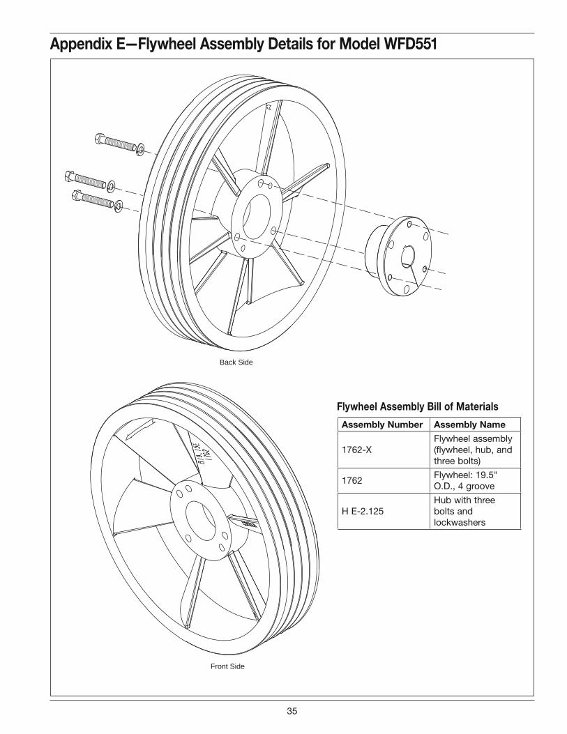
Back Side
Front Side
Appendix E—Flywheel Assembly Details for Model WFD551
Flywheel Assembly Bill of Materials
Assembly Number Assembly Name
1762-XFlywheel assembly (flywheel, hub, and three bolts)
1762Flywheel: 19.5" O.D., 4 groove
H E-2.125Hub with three bolts and lockwashers
35
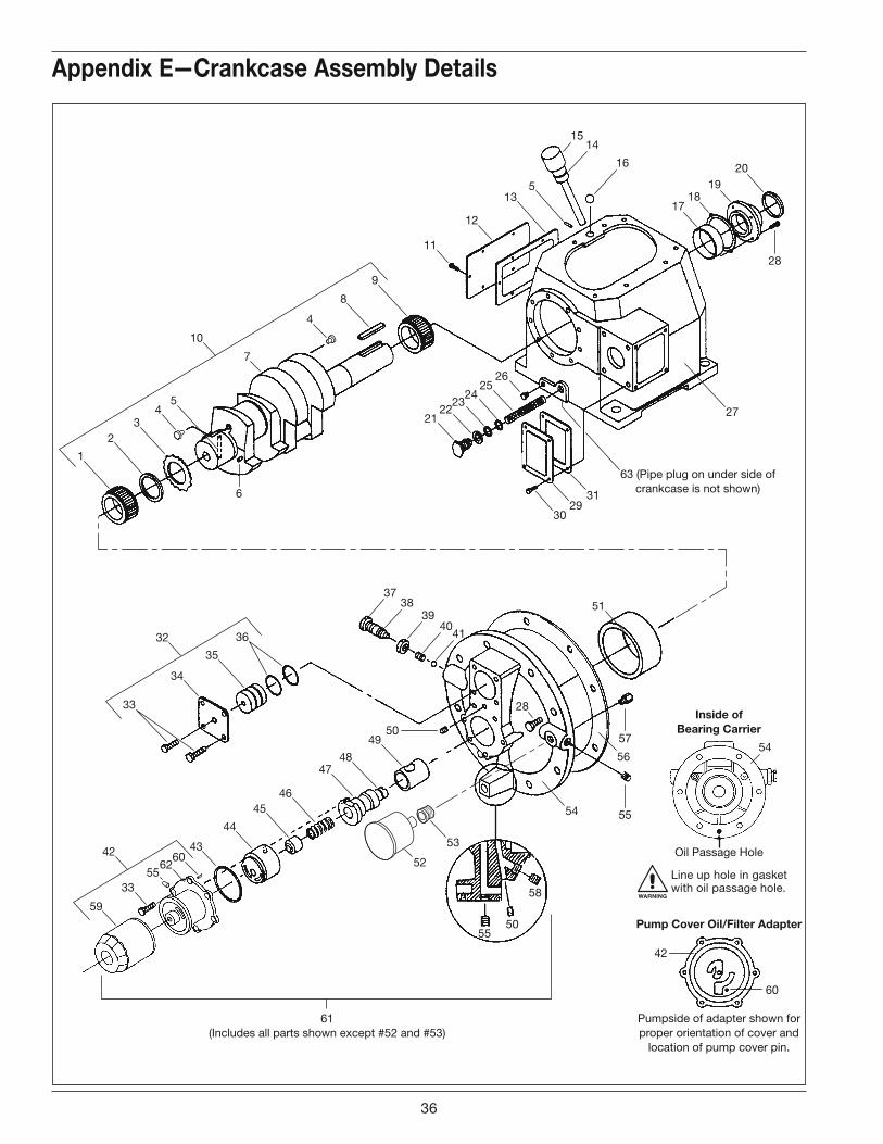
1
23
45
6
7
10
4
30
54
2931
52
53
27
63 (Pipe plug on under side ofcrankcase is not shown)
8
21
17
16
3738
39
4140
15
54
14
1819
20
2223
2425
26
9
11
12
135
33
34
35
43
44
4546
4748
42
51
49
56
50
3632
59
5533
6062
42
28
55
61(Includes all parts shown except #52 and #53)
50
58
Inside ofBearing Carrier
Pump Cover Oil/Filter Adapter
Oil Passage Hole
Pumpside of adapter shown forproper orientation of cover and
location of pump cover pin.
57
55
60
28
Appendix E—Crankcase Assembly Details
WARNING
Line up hole in gasket with oil passage hole.
36
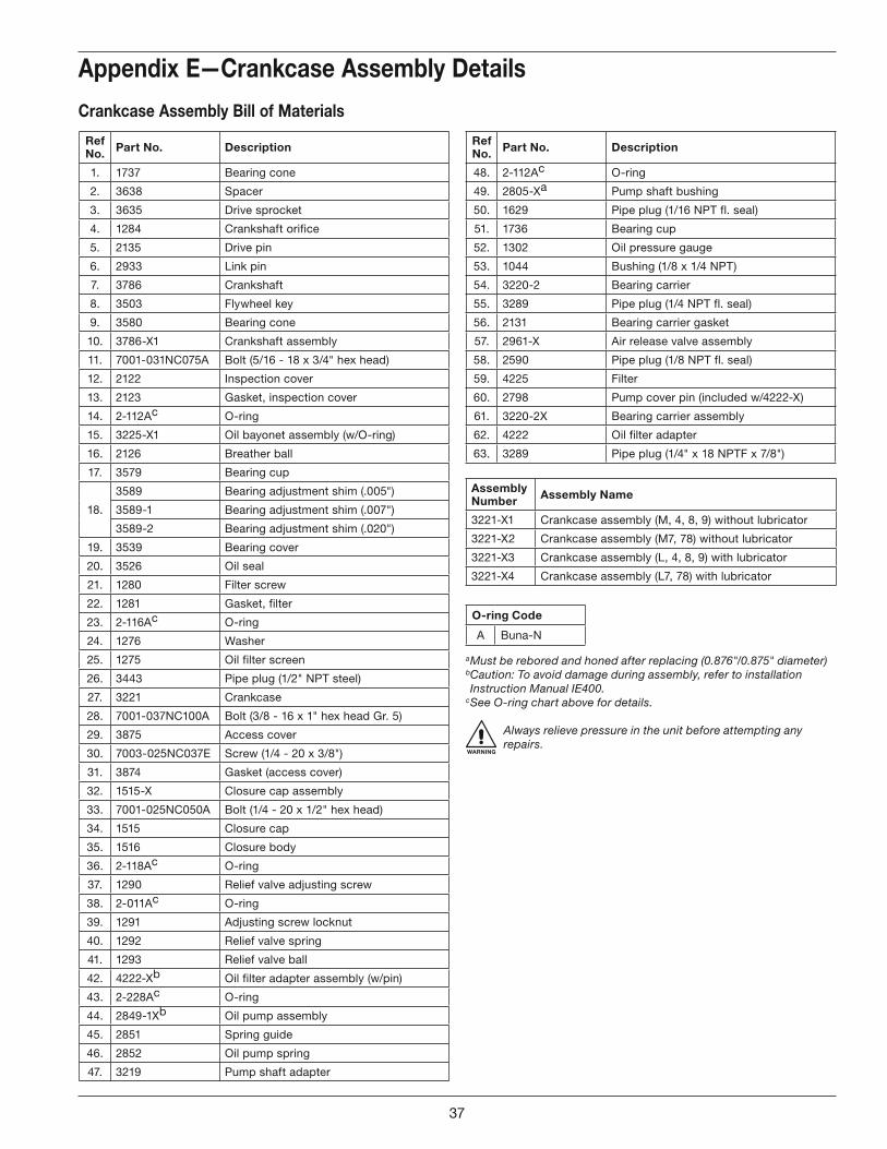
Appendix E—Crankcase Assembly Details
Ref No. Part No. Description
1. 1737 Bearing cone
2. 3638 Spacer
3. 3635 Drive sprocket
4. 1284 Crankshaft orifice
5. 2135 Drive pin
6. 2933 Link pin
7. 3786 Crankshaft
8. 3503 Flywheel key
9. 3580 Bearing cone
10. 3786-X1 Crankshaft assembly
11. 7001-031NC075A Bolt (5/16 - 18 x 3/4" hex head)
12. 2122 Inspection cover
13. 2123 Gasket, inspection cover
14. 2-112Ac O-ring
15. 3225-X1 Oil bayonet assembly (w/O-ring)
16. 2126 Breather ball
17. 3579 Bearing cup
18.
3589 Bearing adjustment shim (.005")
3589-1 Bearing adjustment shim (.007")
3589-2 Bearing adjustment shim (.020")
19. 3539 Bearing cover
20. 3526 Oil seal
21. 1280 Filter screw
22. 1281 Gasket, filter
23. 2-116Ac O-ring
24. 1276 Washer
25. 1275 Oil filter screen
26. 3443 Pipe plug (1/2" NPT steel)
27. 3221 Crankcase
28. 7001-037NC100A Bolt (3/8 - 16 x 1" hex head Gr. 5)
29. 3875 Access cover
30. 7003-025NC037E Screw (1/4 - 20 x 3/8")
31. 3874 Gasket (access cover)
32. 1515-X Closure cap assembly
33. 7001-025NC050A Bolt (1/4 - 20 x 1/2" hex head)
34. 1515 Closure cap
35. 1516 Closure body
36. 2-118Ac O-ring
37. 1290 Relief valve adjusting screw
38. 2-011Ac O-ring
39. 1291 Adjusting screw locknut
40. 1292 Relief valve spring
41. 1293 Relief valve ball
42. 4222-Xb Oil filter adapter assembly (w/pin)
43. 2-228Ac O-ring
44. 2849-1Xb Oil pump assembly
45. 2851 Spring guide
46. 2852 Oil pump spring
47. 3219 Pump shaft adapter
Crankcase Assembly Bill of Materials
Assembly Number Assembly Name
3221-X1 Crankcase assembly (M, 4, 8, 9) without lubricator
3221-X2 Crankcase assembly (M7, 78) without lubricator
3221-X3 Crankcase assembly (L, 4, 8, 9) with lubricator
3221-X4 Crankcase assembly (L7, 78) with lubricator
a Must be rebored and honed after replacing (0.876"/0.875" diameter)b Caution: To avoid damage during assembly, refer to installation Instruction Manual IE400.
c See O-ring chart above for details.
WARNING
Always relieve pressure in the unit before attempting any repairs.
Ref No. Part No. Description
48. 2-112Ac O-ring
49. 2805-Xa Pump shaft bushing
50. 1629 Pipe plug (1/16 NPT fl. seal)
51. 1736 Bearing cup
52. 1302 Oil pressure gauge
53. 1044 Bushing (1/8 x 1/4 NPT)
54. 3220-2 Bearing carrier
55. 3289 Pipe plug (1/4 NPT fl. seal)
56. 2131 Bearing carrier gasket
57. 2961-X Air release valve assembly
58. 2590 Pipe plug (1/8 NPT fl. seal)
59. 4225 Filter
60. 2798 Pump cover pin (included w/4222-X)
61. 3220-2X Bearing carrier assembly
62. 4222 Oil filter adapter
63. 3289 Pipe plug (1/4" x 18 NPTF x 7/8")
O-ring Code
A Buna-N
37
Corken, Inc. • A Unit of IDEX Corporation
3805 N.W. 36th St., Oklahoma City, OK 73112
Phone (405) 946-5576 • Fax (405) 948-7343
Visit our website at http://www.corken.com
or e-mail us at [email protected]
Printed in the U.S.A.July 2012