Embed Size (px)
Citation preview
XK SERIES SCREWCOMPRESSOR
ModelsXK12 ElectricMotor drive
Installation, Operating &MaintenanceManual(Original Instructions)
4990340000September 2013
Page 24990340000 Date:10/05 Electric Motor Driven XK12-Build, Operating & Maintenance Manual
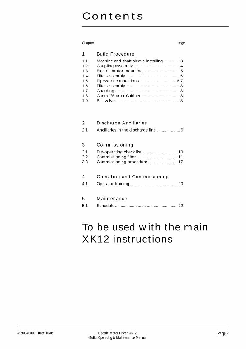
To be used with the mainXK12 instructions
1 Build Procedure
1.1 Machine and shaft sleeve installing .............. 31.2 Coupling assembly ........................................ 41.3 Electric motor mounting ................................ 51.4 Filter assembly ............................................... 61.5 Pipework connections ................................6-71.6 Filter assembly ............................................... 81.7 Guarding ......................................................... 81.8 Control/Starter Cabinet .................................. 81.9 Ball valve ........................................................ 8
2 Discharge Ancillaries
2.1 Ancillaries in the discharge line .................... 9
3 Commissioning
3.1 Pre-operating check list ............................... 103.2 Commissioning filter .................................... 113.3 Commissioning procedure .......................... 17
4 Operating and Commissioning
4.1 Operator training .......................................... 20
5 Maintenance
5.1 Schedule ....................................................... 22
Contents
Chapter Page
Page 34990340000 Date:10/05 Electric Motor Driven XK12-Build, Operating & Maintenance Manual
Build Procedure1
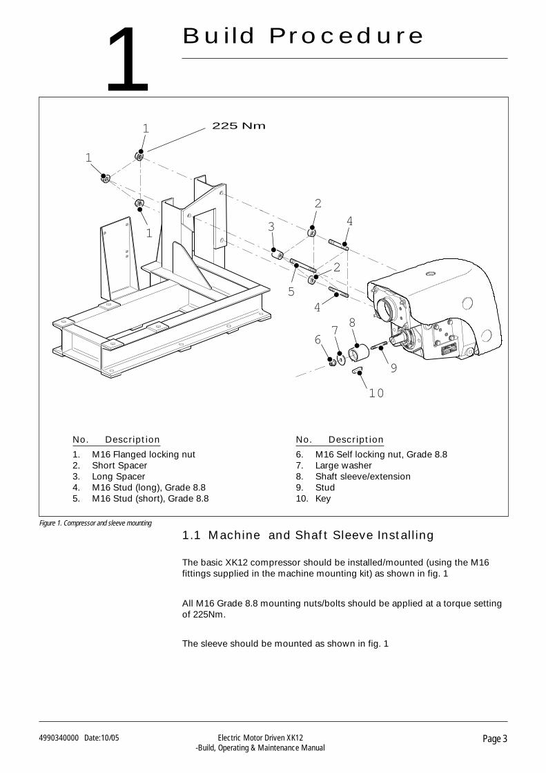
No. Description
1. M16 Flanged locking nut2. Short Spacer3. Long Spacer4. M16 Stud (long), Grade 8.85. M16 Stud (short), Grade 8.8
No. Description
6. M16 Self locking nut, Grade 8.87. Large washer8. Shaft sleeve/extension9. Stud10. Key
Figure 1. Compressor and sleeve mounting
1.1 Machine and Shaft Sleeve Installing
The basic XK12 compressor should be installed/mounted (using the M16fittings supplied in the machine mounting kit) as shown in fig. 1
All M16 Grade 8.8 mounting nuts/bolts should be applied at a torque settingof 225Nm.
The sleeve should be mounted as shown in fig. 1
3
24
45
2
1
1
1
9
10
87
6
225 Nm
Page 44990340000 Date:10/05 Electric Motor Driven XK12-Build, Operating & Maintenance Manual
Build Procedure
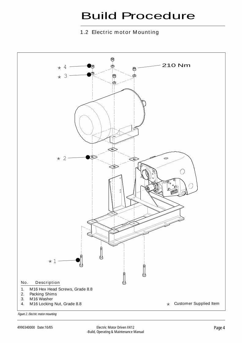
Figure 2. Electric motor mounting
1.2 Electric motor Mounting
* Customer Supplied Item
4
3
1
2
*
*
*
*
210 Nm
No. Description
1. M16 Hex Head Screws, Grade 8.82. Packing Shims3. M16 Washer4. M16 Locking Nut, Grade 8.8
Page 54990340000 Date:10/05 Electric Motor Driven XK12-Build, Operating & Maintenance Manual
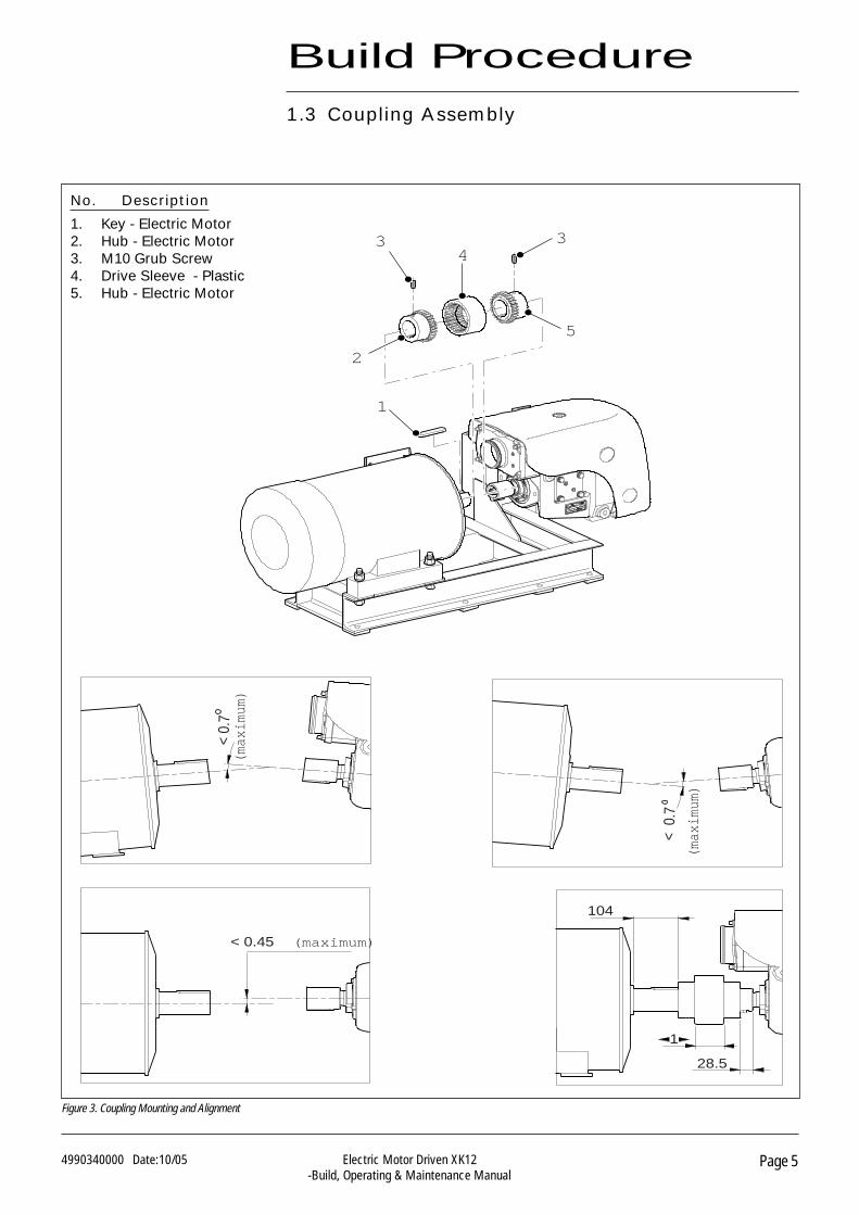
Figure 3. Coupling Mounting and Alignment
Build Procedure
1.3 Coupling Assembly
< 0.45 (maximum)
(max
imum
)
(max
imum
)
5
43 3
2
1
< 0.
7
< 0
.7
104
28.5
1
No. Description
1. Key - Electric Motor2. Hub - Electric Motor3. M10 Grub Screw4. Drive Sleeve - Plastic5. Hub - Electric Motor
Page 64990340000 Date:10/05 Electric Motor Driven XK12-Build, Operating & Maintenance Manual
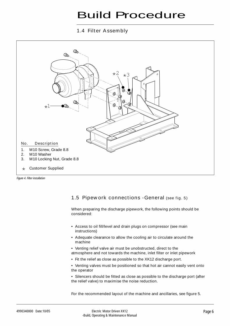
1.4 Filter Assembly
Figure 4. Filter installation
Build Procedure
1.5 Pipework connections -General (see fig. 5)
When preparing the discharge pipework, the following points should beconsidered:
• Access to oil fill/level and drain plugs on compressor (see maininstructions)
• Adequate clearance to allow the cooling air to circulate around themachine
• Venting relief valve air must be unobstructed, direct to theatmosphere and not towards the machine, inlet filter or inlet pipework
• Fit the relief as close as possible to the XK12 discharge port.
• Venting valves must be positioned so that hot air cannot easily vent ontothe operator
• Silencers should be fitted as close as possible to the discharge port (afterthe relief valve) to maximise the noise reduction.
For the recommended layout of the machine and ancillaries, see figure 5.
No. Description
1. M10 Screw, Grade 8.82. M10 Washer3. M10 Locking Nut, Grade 8.8
* Customer Supplied
1
2 3
*
**
Page 74990340000 Date:10/05 Electric Motor Driven XK12-Build, Operating & Maintenance Manual
Build Procedure
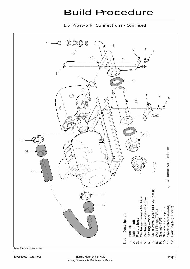
1.5 Pipework Connections - Continued
Figure 5. Pipework Connections
4
*
**12
11
910
7
32
1
8
5
*
6
*
12
***
****
*C
usto
mer
Sup
plie
dIte
m
No
.D
esc
rip
tio
n
1.H
ose
clip
2.R
ubb
ercu
ff3.
Flex
ible
hose
4.D
isch
arge
gask
et-
Mac
hine
5.D
isch
arge
flang
e-
mac
hine
6.S
ealin
gw
ashe
r7.
Rel
iefv
alve
(1.2
5”B
SP,
2.5
bar
g)8.
Wel
dFl
ange
(TW
1)9.
Gas
ket
-T
W1
10.
Sile
ncer
-ab
sorp
tive
11.
Che
ckva
lve
asse
mb
ly12
.C
oup
ling
(e.g
.Sto
rtz)
Page 84990340000 Date:10/05 Electric Motor Driven XK12-Build, Operating & Maintenance Manual
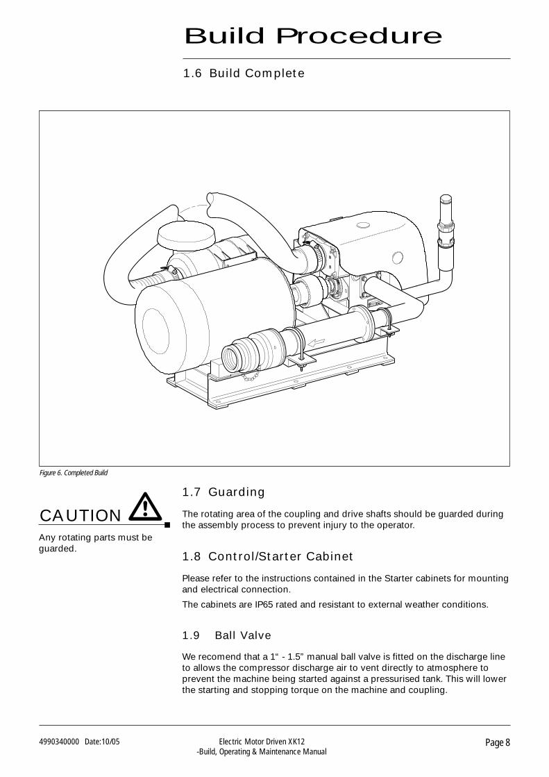
1.7 Guarding
The rotating area of the coupling and drive shafts should be guarded duringthe assembly process to prevent injury to the operator.
1.8 Control/Starter Cabinet
Please refer to the instructions contained in the Starter cabinets for mountingand electrical connection.
The cabinets are IP65 rated and resistant to external weather conditions.
1.9 Ball Valve
We recomend that a 1“ - 1.5” manual ball valve is fitted on the discharge lineto allows the compressor discharge air to vent directly to atmosphere toprevent the machine being started against a pressurised tank. This will lowerthe starting and stopping torque on the machine and coupling.
Any rotating parts must beguarded.
1.6 Build Complete
Build Procedure
Figure 6. Completed Build
CAUTION
Page 94990340000 Date:10/05 Electric Motor Driven XK12-Build, Operating & Maintenance Manual
2.1 Ancillaries in the discharge line
Inlet air filter and flexible induction kit
Should be located so that the inlet air is cool and clean. Do not mount closeto exhausts or other warm air sources.
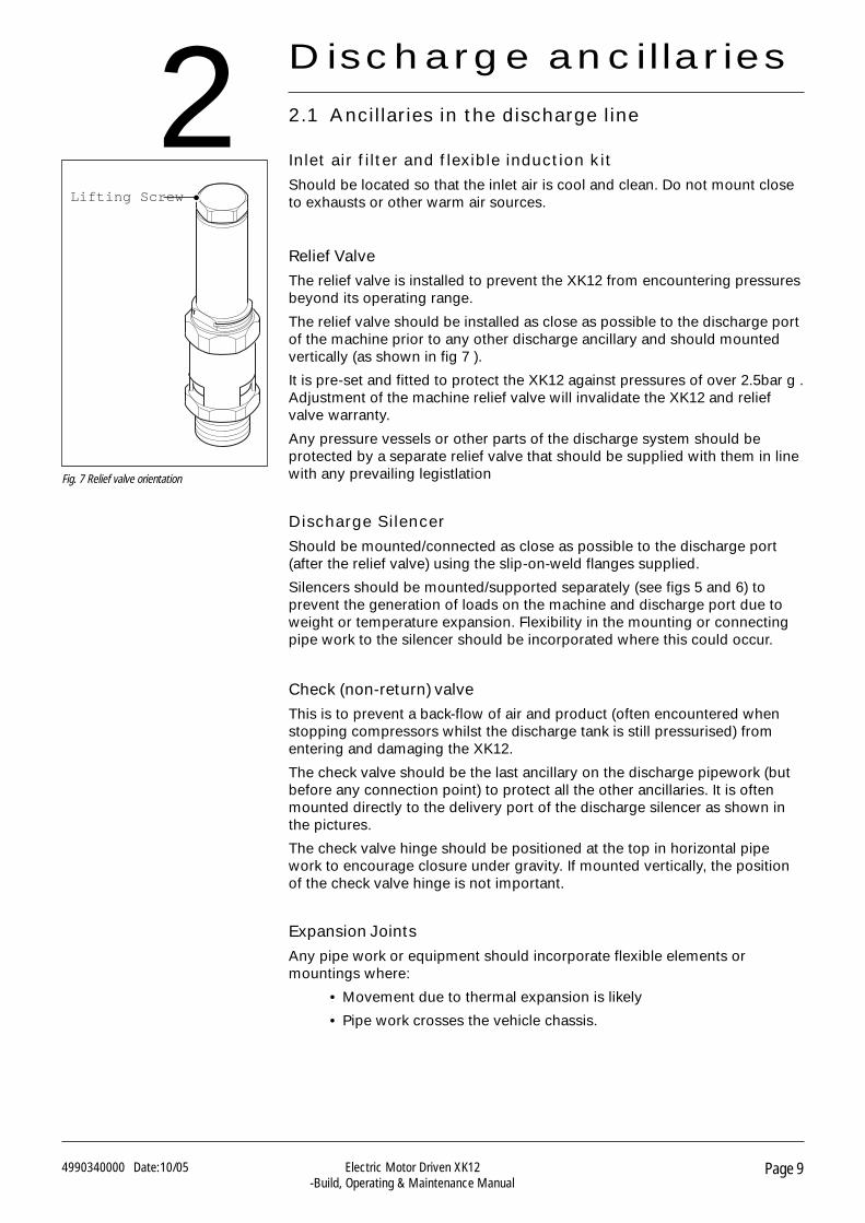
Relief Valve
The relief valve is installed to prevent the XK12 from encountering pressuresbeyond its operating range.
The relief valve should be installed as close as possible to the discharge portof the machine prior to any other discharge ancillary and should mountedvertically (as shown in fig 7 ).
It is pre-set and fitted to protect the XK12 against pressures of over 2.5bar g .Adjustment of the machine relief valve will invalidate the XK12 and reliefvalve warranty.
Any pressure vessels or other parts of the discharge system should beprotected by a separate relief valve that should be supplied with them in linewith any prevailing legistlation
Discharge Silencer
Should be mounted/connected as close as possible to the discharge port(after the relief valve) using the slip-on-weld flanges supplied.
Silencers should be mounted/supported separately (see figs 5 and 6) toprevent the generation of loads on the machine and discharge port due toweight or temperature expansion. Flexibility in the mounting or connectingpipe work to the silencer should be incorporated where this could occur.
Check(non-return)valve
This is to prevent a back-flow of air and product (often encountered whenstopping compressors whilst the discharge tank is still pressurised) fromentering and damaging the XK12.
The check valve should be the last ancillary on the discharge pipework (butbefore any connection point) to protect all the other ancillaries. It is oftenmounted directly to the delivery port of the discharge silencer as shown inthe pictures.
The check valve hinge should be positioned at the top in horizontal pipework to encourage closure under gravity. If mounted vertically, the positionof the check valve hinge is not important.
Expansion Joints
Any pipe work or equipment should incorporate flexible elements ormountings where:
• Movement due to thermal expansion is likely
• Pipe work crosses the vehicle chassis.
Fig. 7 Relief valve orientation
Lifting Screw
Discharge ancillaries2
Page 104990340000 Date:10/05 Electric Motor Driven XK12-Build, Operating & Maintenance Manual
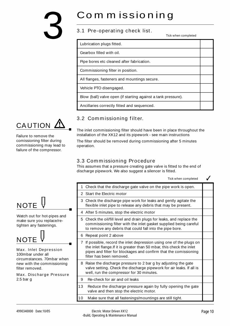
3.3 Commissioning ProcedureThis assumes that a pressure creating gate valve is fitted to the end ofdischarge pipework. We also suggest a silencer is fitted.
3
Watch out for hot-pipes andmake sure you replace/re-tighten any fastenings.
NOTE
Max. Inlet Depression100mbar under allcircumstances. 70mbar whennew with the commissioningfilter removed.
Max. Discharge Pressure2.5 bar g
1 Check that the discharge gate valve on the pipe work is open.
2 Start the Electric motor
3 Check the discharge pipe work for leaks and gently agitate theflexible inlet pipe to release any debris that may be present.
4 After 5 minutes, stop the electric motor
5 Check the oil/fill level and drain plugs for leaks, and replace thecommissioning filter with the inlet gasket supplied being carefulto remove any debris that could fall into the pipe bore.
6 Repeat point 2 above
7 If possible, record the inlet depression using one of the plugs onthe inlet flange.If it is greater than 50 mbar, this check the inletpipes and filter for blockages and confirm that the comissioningfilter has been removed.
8 Raise the discharge pressure to 2 bar g by adjusting the gatevalve setting. Check the discharge pipework for air leaks. If all iswell, run the compressor for 30 minutes.
9 Re-check for air and oil leaks
13 Reduce the discharge pressure again by fully opening the gatevalve and then stop the electric motor.
10 Make sure that all fastenings/mountings are still tight.
Tick when completed
Commissioning
3.1 Pre-operating check list.
3.2 Commissioning filter.
The inlet commissioning filter should have been in place throughout theinstallation of the XK12 and its pipework - see main instructions
The filter should be removed during commissioning after 5 minutesoperation.
Failure to remove thecomissioning filter duringcommissioning may lead tofailure of the compressor.
CAUTION
Lubrication plugs fitted.
Gearbox filled with oil.
Pipe bores etc cleaned after fabrication.
Commissioning filter in position.
All flanges, fasteners and mountings secure.
Vehicle PTO disengaged.
Blow (ball) valve open (if starting against a tank pressure).
Ancillaries correctly fitted and sequenced.
Tick when completed
NOTE
Page 114990340000 Date:10/05 Electric Motor Driven XK12-Build, Operating & Maintenance Manual
4 Training
4.1 Operator training
Driver training should be given when ever possible and should include:-
SafetyInstruct the driver regarding:
• Rotating parts
• Hot Pipework
• Safety valve
• Safety coupling
OperationInstruct the driver regarding:
• Speed range
• Maximum operating pressure
• PTO engagement
• Unloading valve
RoutineMaintenanceInstruct the driver regarding:
• Gearbox oil - topping-up and replacement
• Air filter - cleaning/replacing
• Pipe connections - checking
• Relief valve function
Page 124990340000 Date:10/05 Electric Motor Driven XK12-Build, Operating & Maintenance Manual
5
See the main instructions formaintenance techniques andother information
Maintenance
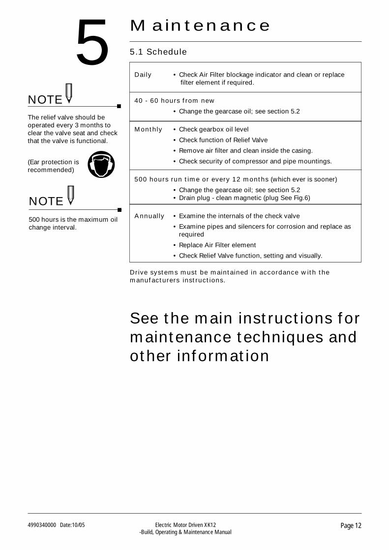
Daily • Check Air Filter blockage indicator and clean or replacefilter element if required.
40 - 60 hours from new
• Change the gearcase oil; see section 5.2
Monthly • Check gearbox oil level
• Check function of Relief Valve
• Remove air filter and clean inside the casing.
• Check security of compressor and pipe mountings.
500 hours run time or every 12 months (which ever is sooner)
• Change the gearcase oil; see section 5.2• Drain plug - clean magnetic (plug See Fig.6)
Annually • Examine the internals of the check valve
• Examine pipes and silencers for corrosion and replace asrequired
• Replace Air Filter element
• Check Relief Valve function, setting and visually.
5.1 Schedule
The relief valve should beoperated every 3 months toclear the valve seat and checkthat the valve is functional.
(Ear protection isrecommended)
NOTE
Drive systems must be maintained in accordance with themanufacturers instructions.
500 hours is the maximum oilchange interval.
NOTE
For additional information, contact your local representative or
Gardner Denver LtdPO Box 178,
Springmill Street, Bradford,
West Yorkshire, UK BD5 7YH
Tel: +44 (0)1274 718100Fax: +44 (0)1274 655272
Email: [email protected] Web: www.gd-transport.com
© 2013 Gardner Denver Ltd.
BelgiumGardner Denver Belgium N.V.Luithagen 7AHaven 200B-2030 AntwerpenBelgiumPhone: +32 (0)3 5415040Fax: +32 (0)3 5416509
email: [email protected]
AmericasGardner Denver, Inc.Industrial Products Group - Americas1800 Gardner ExpresswayQuincy, IL. 62305Toll Free: 1-800-682-9868Phone: 217-222-5400Fax: 217-221-8780
email: [email protected]
NetherlandsGardner Denver Nederland BVBarwoutswaarder 3B3449 He WoerdenThe NetherlandsPhone: +31 (0)348410150Fax: +31 (0)348418079
email: [email protected]
AustraliaGardner Denver Ind. Australia Pty Ltd30 Bearing RoadSeven HillsNew South Wales2147 AustraliaPhone: +61 2 96207000Fax: +61 2 96207955
email: [email protected]
FranceGardner Denver France SADivision Compresseurs42, rue du Montmurier, BP 60438070 Saint-Quentin-Fallavier, FrancePhone: +33 (0)474941673Fax: +33 (0)474941689
email: [email protected]
UK Sales & ServiceGardner Denver UK LtdPO Box 468Cross Lane, TongBradford, West YorkshireUnited KingdomBD4 0SUPhone: +44 (0)1274 683131Fax: +44 (0)1274 651006email: [email protected]
Rest of the WorldGardner Denver LtdPO Box 178Springmill StreetBradford, West YorkshireUnited KingdomBD5 7YHPhone: +44 (0)1274 718100Fax: +44 (0)1274 655272email: [email protected]
GermanyGardner Denver Deutschland GmbHAm Dorn 1448308 SendenGermanyPhone: +49 (0)253634840Fax: +49 (0)25363484010
email: [email protected]
SpainGardner Denver Iberica S.L.Calle Primavera, 20Poligono Industrial Las Monjas28850 Torrejon de ArdozMadrid, SpainPhone: +34 (0)916560056Fax: +34 (0)916770496
email: [email protected]
Contact Us


![(NLF) Harmonised Standards list [ PDF 1274 kB ]](https://img.pdfslide.us/doc/110x75/589ecc5b1a28ab2b4a8be7cb/nlf-harmonised-standards-list-pdf-1274-kb-.jpg)