Embed Size (px)
Citation preview
2TLC172167M0201, rev. E
Original instructions
DaltonProcess lock
ABB Jokab Safety Varlabergsvägen 11, SE-434 39, Sweden www.abb.com/jokabsafety
22TLC172167M0201, rev. E www.abb.com/jokabsafety
Read and understand this documentPlease read and understand this document before using the products. Please consult your ABB JOKAB SAFETY representative if you have any questions or comments.
WARRANTY
ABB JOKAB SAFETY’s exclusive warranty is that the products are free from defects in materials and workmanship for a period of one year (or other period if specified) from date of sale by ABB JOKAB SAFETY.
ABB JOKAB SAFETY MAKES NO WARRANTY OR REPRESENTATION, EXPRESS OR IMPLIED, REGARDING NON-INFRINGEMENT, MERCHANTABILITY, OR FITNESS FOR PARTICULAR PURPOSE OF THE PRODUCTS, ANY BUYER OR USER ACKNOWLEDGES THAT THE BUYER OR USER ALONE HAS DETERMINED THAT THE PRODUCTS WILL SUITABLY MEET THE REQUIREMENTS OR THEIR INTENDED USE. ABB JOKAB SAFETY DISCLAIMS ALL OTHER WARRANTIES, EXPRESS OR IMPLIED.
LIMITATIONS OF LIABILITY
ABB JOKAB SAFETY SHALL NOT BE RESPONSIBLE FOR SPECIAL, INDIRECT, OR CONSEQUENTIAL DAMAGES, LOSS OF PROFITS OR COMMERCIAL LOSS IN ANY WAY CONNECTED WITH THE PRODUCTS, WHETHER SUCH CLAIM IS BASED ON CONTRACT, WARRANTY, NEGLIGENCE, OR STRICT LIABILITY.
In no event shall responsibility of ABB JOKAB SAFETY for any act exceed the individual price of the product on which liability asserted.
IN NO EVENT SHALL ABB JOKAB SAFETY BE RESPONSIBLE FOR WARRANTY, REPAIR, OR OTHER CLAIMS REGARDING THE PRODUCTS UNLESS ABB JOKAB SAFETY’S ANALYSIS CONFIRMS THAT THE PRODUCTS WERE PROPERLY HANDLED, STORED, INSTALLED, AND MAINTAINED AND NOT SUBJECT TO ABUSE, MISUSE, OR INAPPROPRIATE MODIFICATION OR REPAIR.
SUITABILITY FOR USE
ABB JOKAB SAFETY shall not be responsible for conformity with any standards, codes, or regulations that apply to the combination of products in the customer’s application or use of the product.
At the customer’s request, ABB JOKAB SAFETY will provide applicable third party certification documents identifying ratings and limitations of use that apply to the products. This information by itself is not sufficient for a complete determination of the suitability of the products in combination with the end product, machine, system, or other application or use.
The following are some examples of applications for which particular attention must be given. This is not intended to be an exhaustive list of all possible uses of the products, nor is it intended to imply that the uses listed may be suitable for the products:
Outdoor use, uses involving potential chemical contamination or electrical interference, or conditions or uses not described in this document.
Nuclear energy control systems, combustion systems, railroad systems, aviation systems, medical equipment, amusement machines, vehicles, and installations subject to separate industry or government regulations.
Systems, machines, and equipment that could present a risk to life or property.
Please know and observe all prohibitions of use applicable to the products.
NEVER USE THE PRODUCTS FOR AN APPLICATION INVOLVING SERIOUS RISK TO LIFE OR PROPERTY WITHOUT ENSURING THAT THE SYSTEM AS A WHOLE HAS BEEN DESIGNED TO ADDRESS THE RISKS, AND THAT THE ABB JOKAB SAFETY PRODUCT IS PROPERLY RATED AND INSTALLED FOR THE INTENDED USE WITHIN THE OVERALL EQUIPMENT OR SYSTEM.
PERFORMANCE DATA
While every effort has been taken to ensure the accuracy of the information contained in this manual ABB JOKAB SAFETY cannot accept responsibility for errors or omissions and reserves the right to make changes and improvements without notice.Performance data given in this document is provided as a guide for the user in determining suitability and does not constitute a warranty. It may represent the result of ABB JOKAB SAFETY’S test conditions, and the users must correlate it to actual application requirements. Actual performance is subject to the ABB JOKAB SAFETY Warranty and Limitations of Liability.
3www.abb.com/jokabsafety 2TLC172167M0201, rev. E
1 Dalton - the intelligent process lock ..............................................51.1 Basic versions ........................................................................................... 5
2 General information .........................................................................62.1 Installation precautions ............................................................................. 62.2 Maintenance .............................................................................................. 62.3 In case of functional problems .................................................................. 62.4 Force to open ............................................................................................ 6
3 Mechanical design ...........................................................................73.1 Opening directions .................................................................................... 73.2 Detection of tongue ................................................................................... 83.3 Location of tongue towards Dalton ............................................................ 83.4 Adjustment of tongue ................................................................................ 93.5 Adjusting tension of the lock ................................................................... 103.6 Distance from hinge to tongue ................................................................ 113.7 Vertical installation .................................................................................. 123.8 Horizontal installation .............................................................................. 12
4 Electrical connections ...................................................................135 Connection examples ....................................................................146 Distribution blocks and special cables ........................................16
6.1 Distribution block Tina 12A ...................................................................... 166.2 Transfer cables ........................................................................................ 16
7 Dalton in combination with brackets ...........................................177.1 The basic Dalton versions ....................................................................... 177.2 Mounting brackets for Dalton .................................................................. 177.3 Mounting brackets for Dalton and Eden .................................................. 187.4 Mounting brackets for ABB/Jokab Safety Quick-Guard fence ................. 187.5 Mounting brackets with small bracket for tongue .................................... 197.6 Tongue .................................................................................................... 19
Table of contents
42TLC172167M0201, rev. E www.abb.com/jokabsafety
8 Assembly of Dalton and mounting bracket .................................209 Measurements ................................................................................21
9.1 Dalton with bracket 1 ............................................................................... 219.2 Dalton with bracket 2 ............................................................................... 219.3 Dalton with bracket 3 ............................................................................... 229.4 Dalton with bracket 4 ............................................................................... 229.5 Dalton with bracket 5 ............................................................................... 239.6 Dalton with bracket 6 ............................................................................... 23
10 Technical data ................................................................................2410.1 Indication and information ....................................................................... 2410.2 Connectors .............................................................................................. 2410.3 Pins (colour markings) ............................................................................ 2410.4 Data ......................................................................................................... 25
11 11 EC Declaration of conformity ..................................................26

5www.abb.com/jokabsafety 2TLC172167M0201, rev. E
1 Dalton - the intelligent process lockDalton is a locking unit that is intended for use in preventing unnecessary production stoppages, i.e. it is not a safety lock. It can be used either as a stand-alone lock or integrated with Eden (as a safety sensor). In the unlocked state the door is held closed by a ball catch and locked mechanically. If necessary, the holding force of the ball catch can be adjusted. The unit only permits locking if the ball catch is secured and when Eva is in contact with Adam (depending on variant). When the lock input is set, the ball catch is locked.
Dalton is easily connected with an M12 connector. A Tina junction block may also be used for distribution of the safety as well as locking functions. The Dalton status is indicated by LEDs and can also be read by PLC via the information output.
1.1 Basic versionsFour major versions of Dalton are available and can be combined with several mounting brackets. There are different types of Dalton depending on the actual requirements. The L-type is a ball catch without internal electronics. The M-type is a process lock with power to lock. There is a possibillity to choose between three versions of the M-type. Two versions with 8-pole connectors. The Dalton M11 without possibillity for connecting Eden and Dalton M12 with a 5-pole connector for Eden and easily distributed back to the electrical cabinet with the 8-pole cable including the functions needed controlling the Dalton. The M31 has a 5-pole connector (otherwise the same as M11) and the L00 version is without internal electronics.
Dalton M11 Dalton M12
Dalton M31 Dalton L00
62TLC172167M0201, rev. E www.abb.com/jokabsafety
2 General information2.1 Installation precautionsThe Dalton lock shall be installed by trained personnel following the Safety regulations, standards and the Machine directive. All safety functions shall be tested before the starting up of the machine.
2.2 MaintenanceBefore performing maintenance - Do not open the Dalton prior the warranty has elapsed. Opened units will not be given warranty if claims are made.
The ball-catch is lubricated from factory. More lubrication can be added when needed. Dismount the end caps and adjustment screws. Remove the springs, pistons and balls. Add grease on the ball seat, springs, pistons and balls.
Remount the details.
Warning! The piston o-rings may not be damaged. This will have an negative effect on the IP-rating. Caution! This product shall be handled with caution. The product should be replaced with the same type of product if there is a situation where it has been dropped on the floor, knocked strongly, exposed to extreme voltages, temperatures or humidity beyond the specified limits. Dalton may never be used as a door stop.
Note! In locked state Dalton might emit a low frequent noise. This is caused by the supervision of the locking function and is fully normal. Neither function nor lifetime will be affected.
2.3 In case of functional problemsThe entire system should be tested without disconnecting the power supply. Check the LED indicators according to ”Indication and information” under the chapter ”Technical data“ in this manual. If the problem is not solved, please contact the nearest ABB/Jokab Safety Service Office or reseller.
2.4 Force to openDo not attempt to force the lock open while Dalton is locked, as it will cause permanent damage to the device.
7www.abb.com/jokabsafety 2TLC172167M0201, rev. E
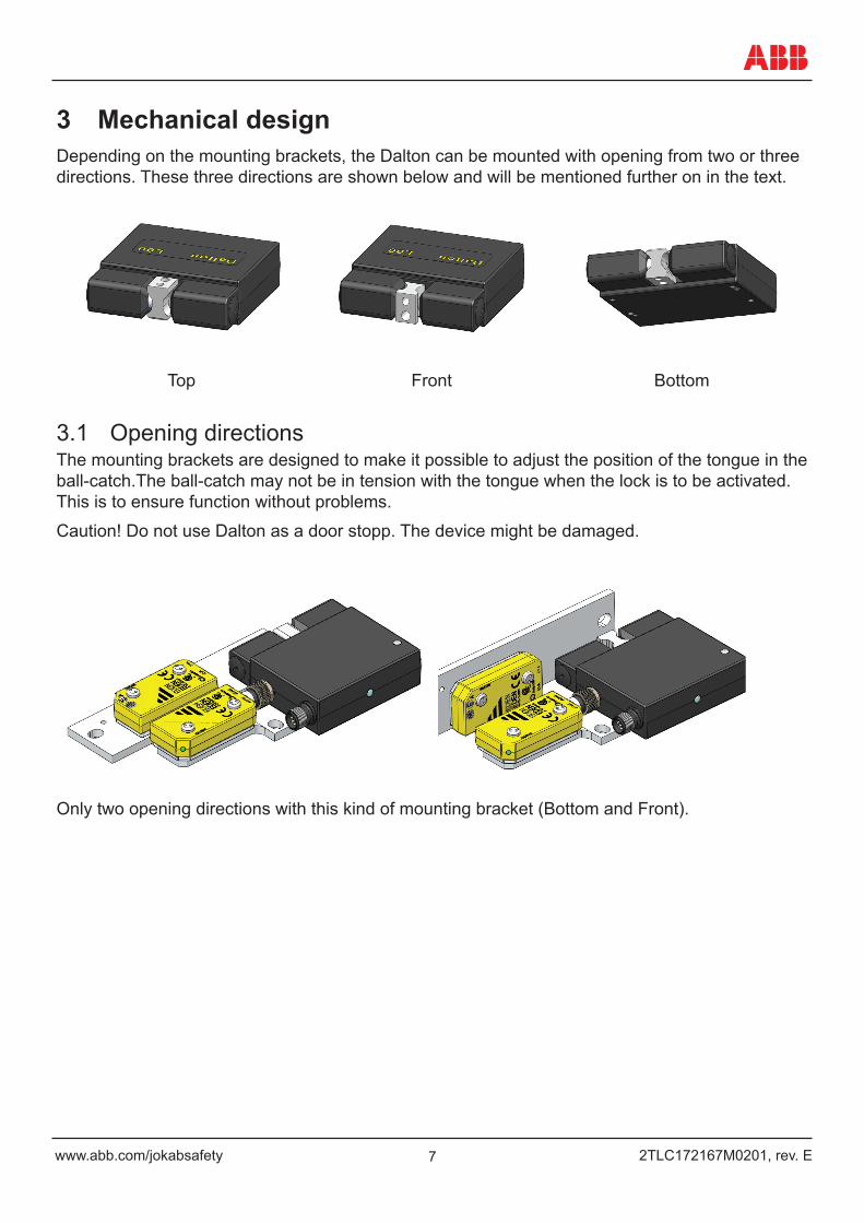
3 Mechanical designDepending on the mounting brackets, the Dalton can be mounted with opening from two or three directions. These three directions are shown below and will be mentioned further on in the text.
Top Front Bottom
3.1 Opening directionsThe mounting brackets are designed to make it possible to adjust the position of the tongue in the ball-catch.The ball-catch may not be in tension with the tongue when the lock is to be activated. This is to ensure function without problems.
Caution! Do not use Dalton as a door stopp. The device might be damaged.
Only two opening directions with this kind of mounting bracket (Bottom and Front).
82TLC172167M0201, rev. E www.abb.com/jokabsafety
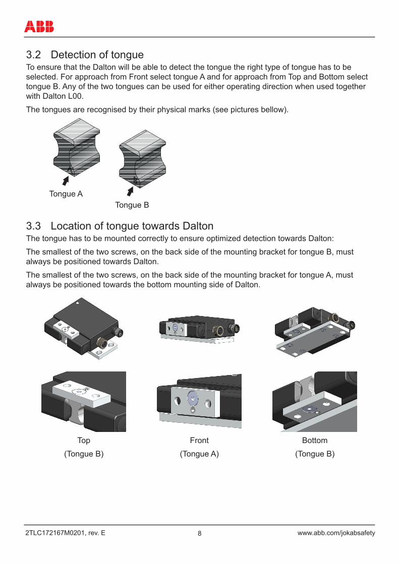
3.2 Detection of tongueTo ensure that the Dalton will be able to detect the tongue the right type of tongue has to be selected. For approach from Front select tongue A and for approach from Top and Bottom select tongue B. Any of the two tongues can be used for either operating direction when used together with Dalton L00.
The tongues are recognised by their physical marks (see pictures bellow).
3.3 Location of tongue towards DaltonThe tongue has to be mounted correctly to ensure optimized detection towards Dalton:
The smallest of the two screws, on the back side of the mounting bracket for tongue B, must always be positioned towards Dalton.
The smallest of the two screws, on the back side of the mounting bracket for tongue A, must always be positioned towards the bottom mounting side of Dalton.
Top
(Tongue B)
Front
(Tongue A)
Bottom
(Tongue B)
Tongue ATongue B

9www.abb.com/jokabsafety 2TLC172167M0201, rev. E
3.4 Adjustment of tongueWhen the door is closed the balls of the ball-catch must not be pressed by the tongue. The lock has to be mounted so that the tongue is well centered in the ball-catch in the X-direction and within the measurements stated for the Y- and Z-directions. When the balls are under pressure, the lock will not work reliably and the dust and liquid protection is reduced.
X
Y
X
Z
Front Top, Bottom
X: +/- 0,6 mm Y: +/- 5 mm Z: Min 2 mm, max 4 mm
102TLC172167M0201, rev. E www.abb.com/jokabsafety
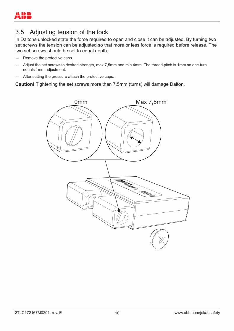
3.5 Adjusting tension of the lockIn Daltons unlocked state the force required to open and close it can be adjusted. By turning two set screws the tension can be adjusted so that more or less force is required before release. The two set screws should be set to equal depth.
– Remove the protective caps.
– Adjust the set screws to desired strength, max 7,5mm and min 4mm. The thread pitch is 1mm so one turn equals 1mm adjustment.
– After setting the pressure attach the protective caps.
Caution! Tightening the set screws more than 7.5mm (turns) will damage Dalton.
0mm Max 7,5mm
11www.abb.com/jokabsafety 2TLC172167M0201, rev. E
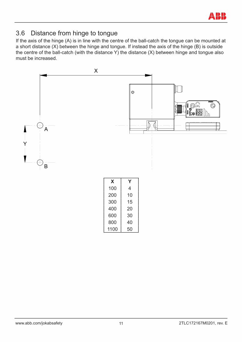
3.6 Distance from hinge to tongueIf the axis of the hinge (A) is in line with the centre of the ball-catch the tongue can be mounted at a short distance (X) between the hinge and tongue. If instead the axis of the hinge (B) is outside the centre of the ball-catch (with the distance Y) the distance (X) between hinge and tongue also must be increased.
X
Y
A
B
X Y100 4200 10300 15400 20600 30800 401100 50
122TLC172167M0201, rev. E www.abb.com/jokabsafety
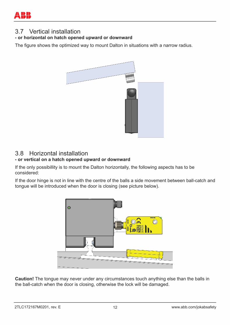
3.7 Vertical installation- or horizontal on hatch opened upward or downwardThe figure shows the optimized way to mount Dalton in situations with a narrow radius.
3.8 Horizontal installation- or vertical on a hatch opened upward or downwardIf the only possibillity is to mount the Dalton horizontally, the following aspects has to be considered:
If the door hinge is not in line with the centre of the balls a side movement between ball-catch and tongue will be introduced when the door is closing (see picture below).
Caution! The tongue may never under any circumstances touch anything else than the balls in the ball-catch when the door is closing, otherwise the lock will be damaged.
13www.abb.com/jokabsafety 2TLC172167M0201, rev. E
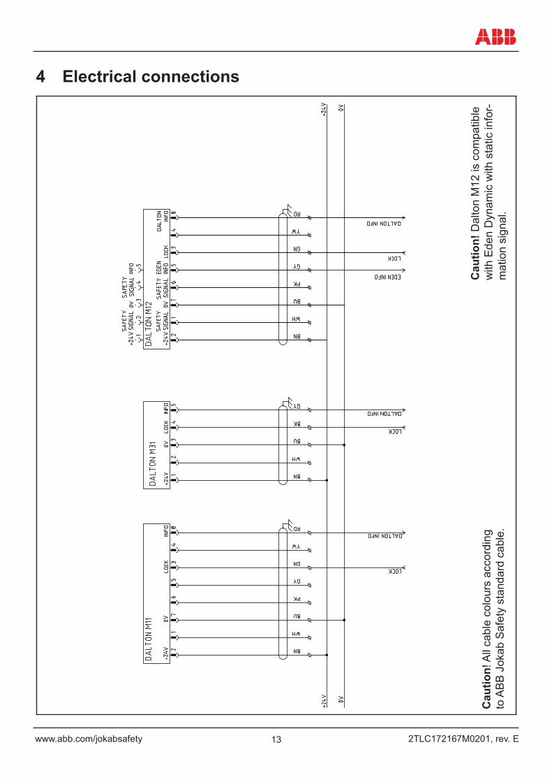
4 Electrical connections
Caution! D
alton M
12 is c
om
patible
with E
den D
ynam
ic w
ith s
tatic
info
rmation s
ignal.
Cau
tion!
All
cabl
e co
lour
s ac
cord
ing
to A
BB
Jok
ab S
afet
y st
anda
rd c
able
.
Cau
tion!
Dal
ton
M12
is c
ompa
tible
w
ith E
den
Dyn
amic
with
sta
tic in
for-
mat
ion
sign
al.
142TLC172167M0201, rev. E www.abb.com/jokabsafety
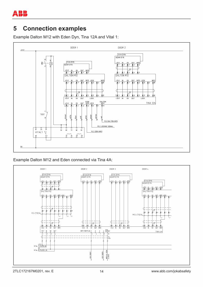
5 Connection examplesExample Dalton M12 with Eden Dyn, Tina 12A and Vital 1:
Example Dalton M12 and Eden connected via Tina 4A:
15www.abb.com/jokabsafety 2TLC172167M0201, rev. E
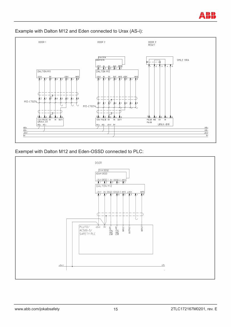
Example with Dalton M12 and Eden connected to Urax (AS-i):
Exempel with Dalton M12 and Eden-OSSD connected to PLC:
162TLC172167M0201, rev. E www.abb.com/jokabsafety
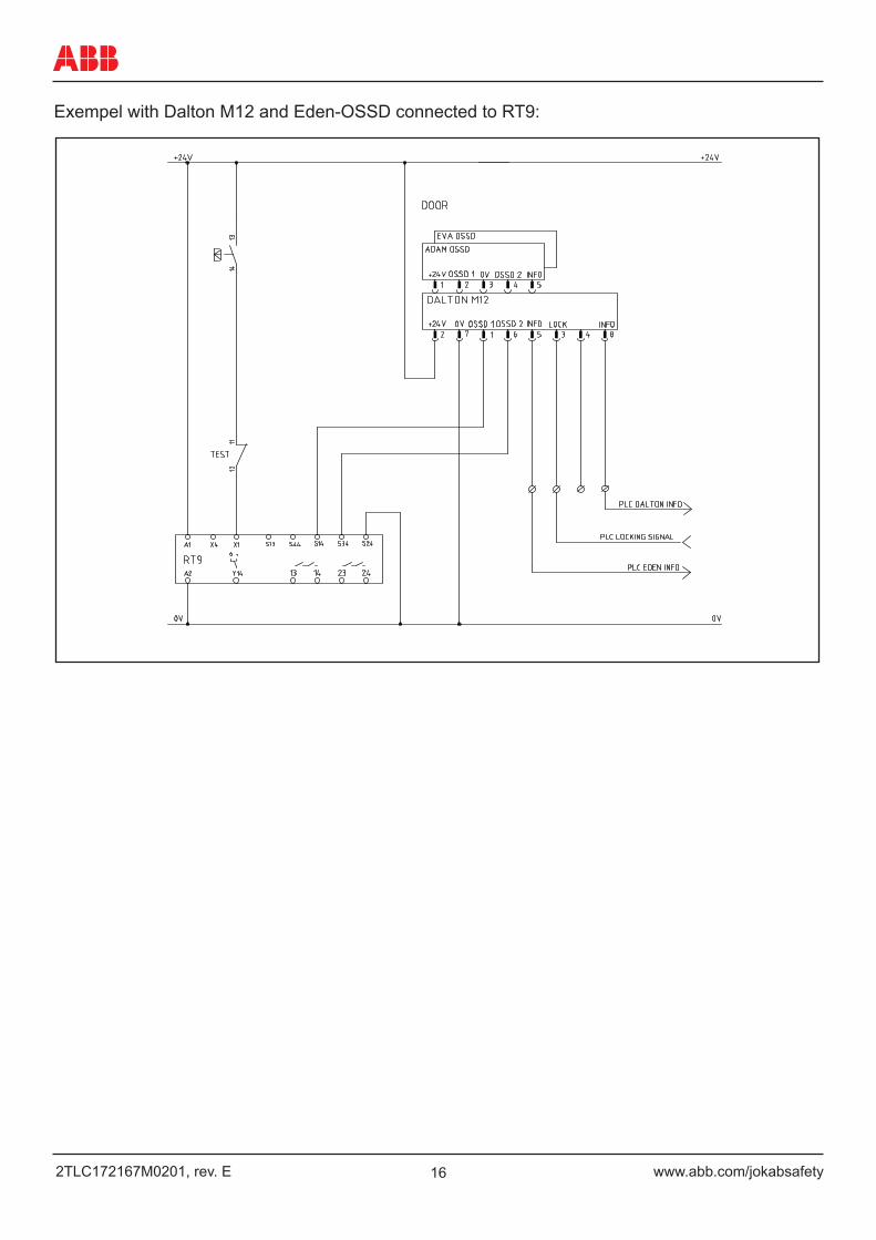
Exempel with Dalton M12 and Eden-OSSD connected to RT9:
17www.abb.com/jokabsafety 2TLC172167M0201, rev. E
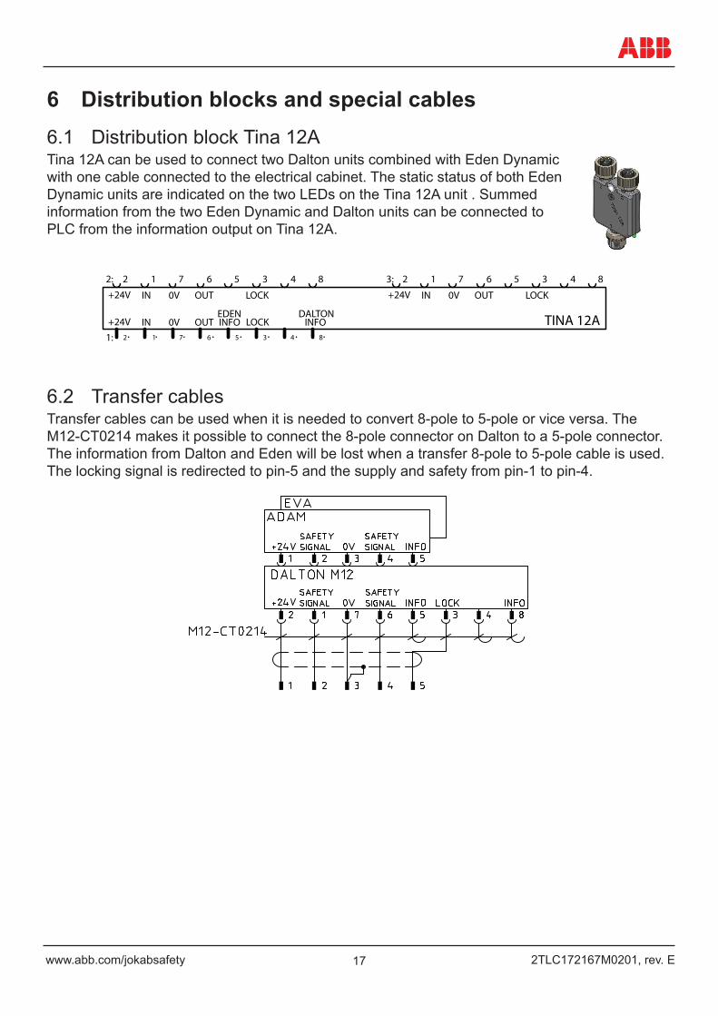
6 Distribution blocks and special cables6.1 Distribution block Tina 12ATina 12A can be used to connect two Dalton units combined with Eden Dynamic with one cable connected to the electrical cabinet. The static status of both Eden Dynamic units are indicated on the two LEDs on the Tina 12A unit . Summed information from the two Eden Dynamic and Dalton units can be connected to PLC from the information output on Tina 12A.
DALTONEDENLOCK
3 4 8
INFO
+24V LOCK
3 4 8
IN
2
OUT0V
1 7 6 5
LOCK
3 4 8 3:
1:
2:X107
IN
+24V IN
+24V
2
OUT
OUT
0V
0V
1 7 6 5
TINA 12A2 1 7 6 5
INFO
6.2 Transfer cablesTransfer cables can be used when it is needed to convert 8-pole to 5-pole or vice versa. The M12-CT0214 makes it possible to connect the 8-pole connector on Dalton to a 5-pole connector. The information from Dalton and Eden will be lost when a transfer 8-pole to 5-pole cable is used. The locking signal is redirected to pin-5 and the supply and safety from pin-1 to pin-4.
182TLC172167M0201, rev. E www.abb.com/jokabsafety
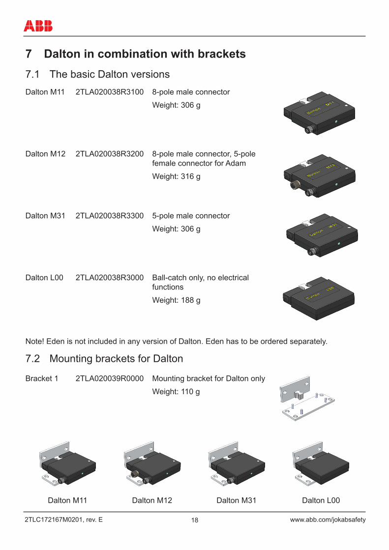
7 Dalton in combination with brackets7.1 The basic Dalton versionsDalton M11 2TLA020038R3100 8-pole male connector
Weight: 306 g
Dalton M12 2TLA020038R3200 8-pole male connector, 5-pole female connector for Adam
Weight: 316 g
Dalton M31 2TLA020038R3300 5-pole male connector
Weight: 306 g
Dalton L00 2TLA020038R3000 Ball-catch only, no electrical functions
Weight: 188 g
Note! Eden is not included in any version of Dalton. Eden has to be ordered separately.
7.2 Mounting brackets for Dalton
Bracket 1 2TLA020039R0000 Mounting bracket for Dalton only
Weight: 110 g
Dalton M11 Dalton M12 Dalton M31 Dalton L00
19www.abb.com/jokabsafety 2TLC172167M0201, rev. E
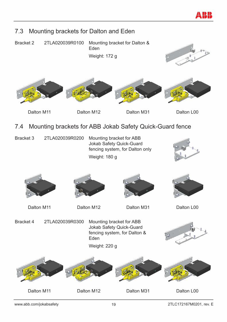
7.3 Mounting brackets for Dalton and Eden
Bracket 2 2TLA020039R0100 Mounting bracket for Dalton & Eden
Weight: 172 g
Dalton M11 Dalton M12 Dalton M31 Dalton L00
7.4 Mounting brackets for ABB Jokab Safety Quick-Guard fence
Bracket 3 2TLA020039R0200 Mounting bracket for ABB Jokab Safety Quick-Guard fencing system, for Dalton only
Weight: 180 g
Dalton M11 Dalton M12 Dalton M31 Dalton L00
Bracket 4 2TLA020039R0300 Mounting bracket for ABB Jokab Safety Quick-Guard fencing system, for Dalton & Eden
Weight: 220 g
Dalton M11 Dalton M12 Dalton M31 Dalton L00
202TLC172167M0201, rev. E www.abb.com/jokabsafety
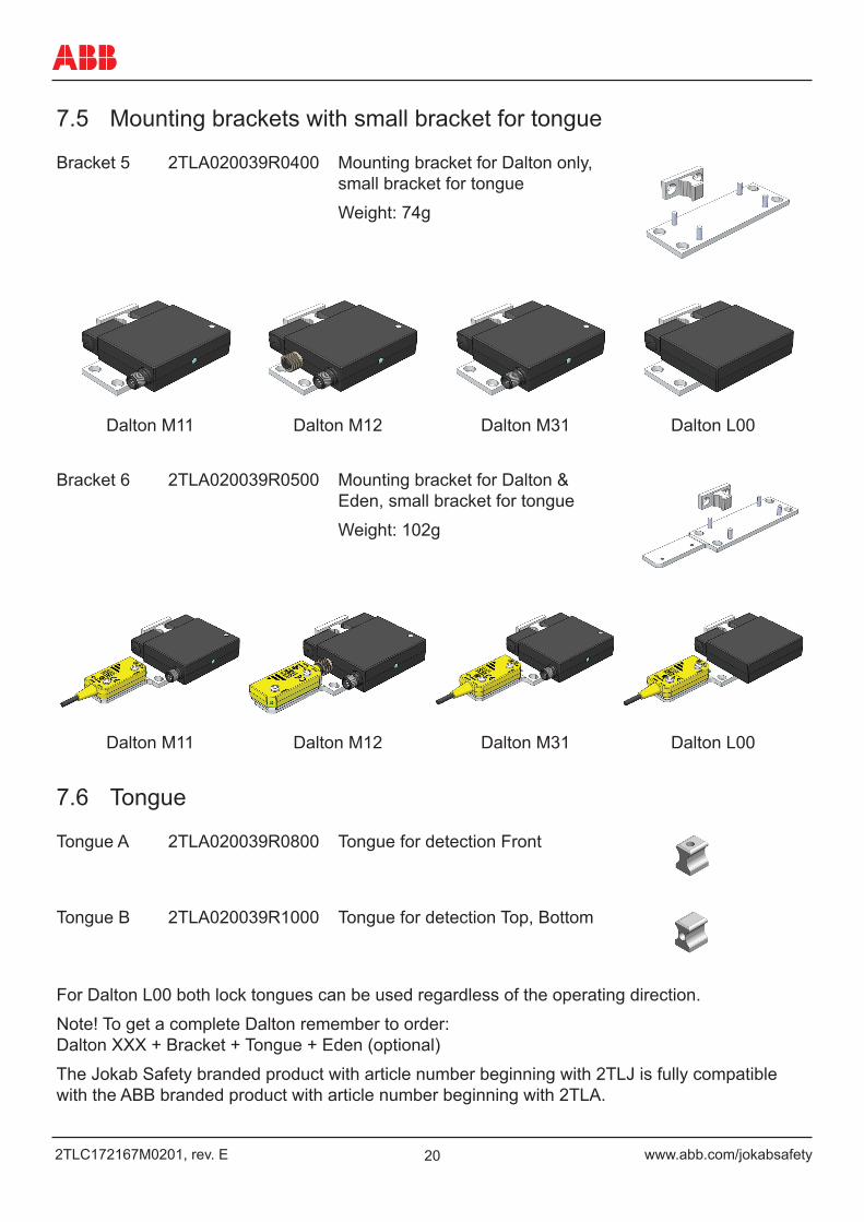
7.5 Mounting brackets with small bracket for tongue
Bracket 5 2TLA020039R0400 Mounting bracket for Dalton only, small bracket for tongue
Weight: 74g
Dalton M11 Dalton M12 Dalton M31 Dalton L00
Bracket 6 2TLA020039R0500 Mounting bracket for Dalton & Eden, small bracket for tongue
Weight: 102g
Dalton M11 Dalton M12 Dalton M31 Dalton L00
7.6 Tongue
Tongue A 2TLA020039R0800 Tongue for detection Front
Tongue B 2TLA020039R1000 Tongue for detection Top, Bottom
For Dalton L00 both lock tongues can be used regardless of the operating direction.
Note! To get a complete Dalton remember to order: Dalton XXX + Bracket + Tongue + Eden (optional)
The Jokab Safety branded product with article number beginning with 2TLJ is fully compatible with the ABB branded product with article number beginning with 2TLA.
21www.abb.com/jokabsafety 2TLC172167M0201, rev. E
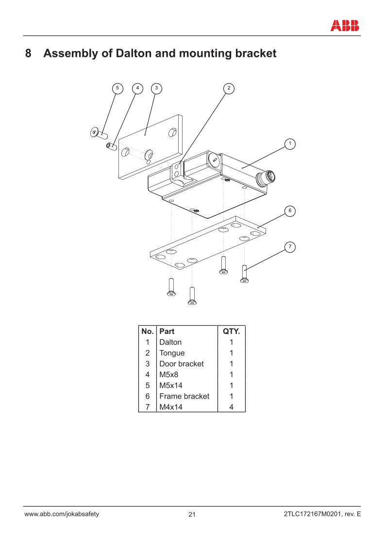
8 Assembly of Dalton and mounting bracket
1
3 5
6
4 2
7
No. Part QTY.1 Dalton 12 Tongue 13 Door bracket 14 M5x8 15 M5x14 16 Frame bracket 17 M4x14 4
222TLC172167M0201, rev. E www.abb.com/jokabsafety
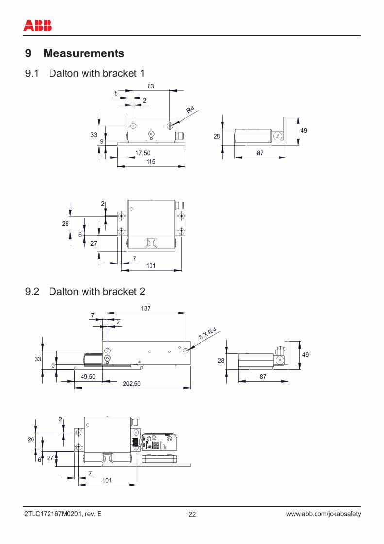
9 Measurements9.1 Dalton with bracket 1
49 28 33
9
2
6 27
26
8 2
63
17,50 115
R 4
7 101
87
9.2 Dalton with bracket 2
33 9
28 49
2
27
26
6
7 2
137
49,50 202,50
8 X R 4
87
7 101
23www.abb.com/jokabsafety 2TLC172167M0201, rev. E
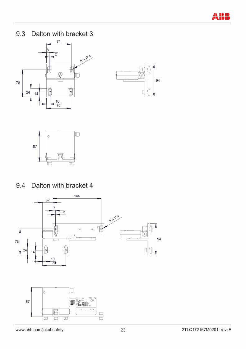
9.3 Dalton with bracket 3
78
24 14
94
87
1070
82
71
8 X R 4
9.4 Dalton with bracket 4
24
78
14
87
94
10 70
2
32
7
144
8 X R 4
242TLC172167M0201, rev. E www.abb.com/jokabsafety
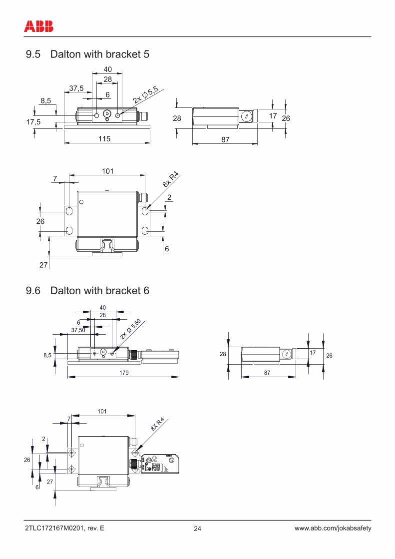
9.5 Dalton with bracket 5
101 7
26
27
8x R
4
6
2
115
37,5 6
28
2x 5,5
40
17,5
8,5
17 26 28
87
9.6 Dalton with bracket 6
8,5 28 26 17
26
27
2
6
179
37,50 6
28 40
2X Ø
5,50
7 101
8X R
4
87
25www.abb.com/jokabsafety 2TLC172167M0201, rev. E
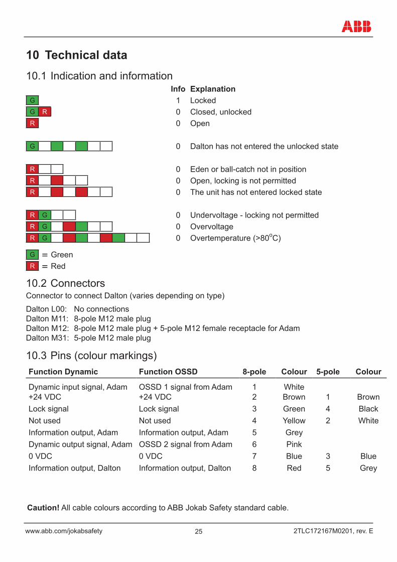
10 Technical data10.1 Indication and information
Info ExplanationG 1 LockedG R 0 Closed, unlockedR 0 Open
G 0 Dalton has not entered the unlocked state
R 0 Eden or ball-catch not in positionR 0 Open, locking is not permittedR 0 The unit has not entered locked state
R G 0 Undervoltage - locking not permittedR G 0 OvervoltageR G 0 Overtemperature (>80oC)
G = GreenR = Red
10.2 ConnectorsConnector to connect Dalton (varies depending on type)
Dalton L00: No connections Dalton M11: 8-pole M12 male plug Dalton M12: 8-pole M12 male plug + 5-pole M12 female receptacle for Adam Dalton M31: 5-pole M12 male plug
10.3 Pins (colour markings)Function Dynamic Function OSSD 8-pole Colour 5-pole Colour
Dynamic input signal, Adam OSSD 1 signal from Adam 1 White+24 VDC +24 VDC 2 Brown 1 BrownLock signal Lock signal 3 Green 4 BlackNot used Not used 4 Yellow 2 WhiteInformation output, Adam Information output, Adam 5 GreyDynamic output signal, Adam OSSD 2 signal from Adam 6 Pink0 VDC 0 VDC 7 Blue 3 BlueInformation output, Dalton Information output, Dalton 8 Red 5 Grey
Caution! All cable colours according to ABB Jokab Safety standard cable.
262TLC172167M0201, rev. E www.abb.com/jokabsafety
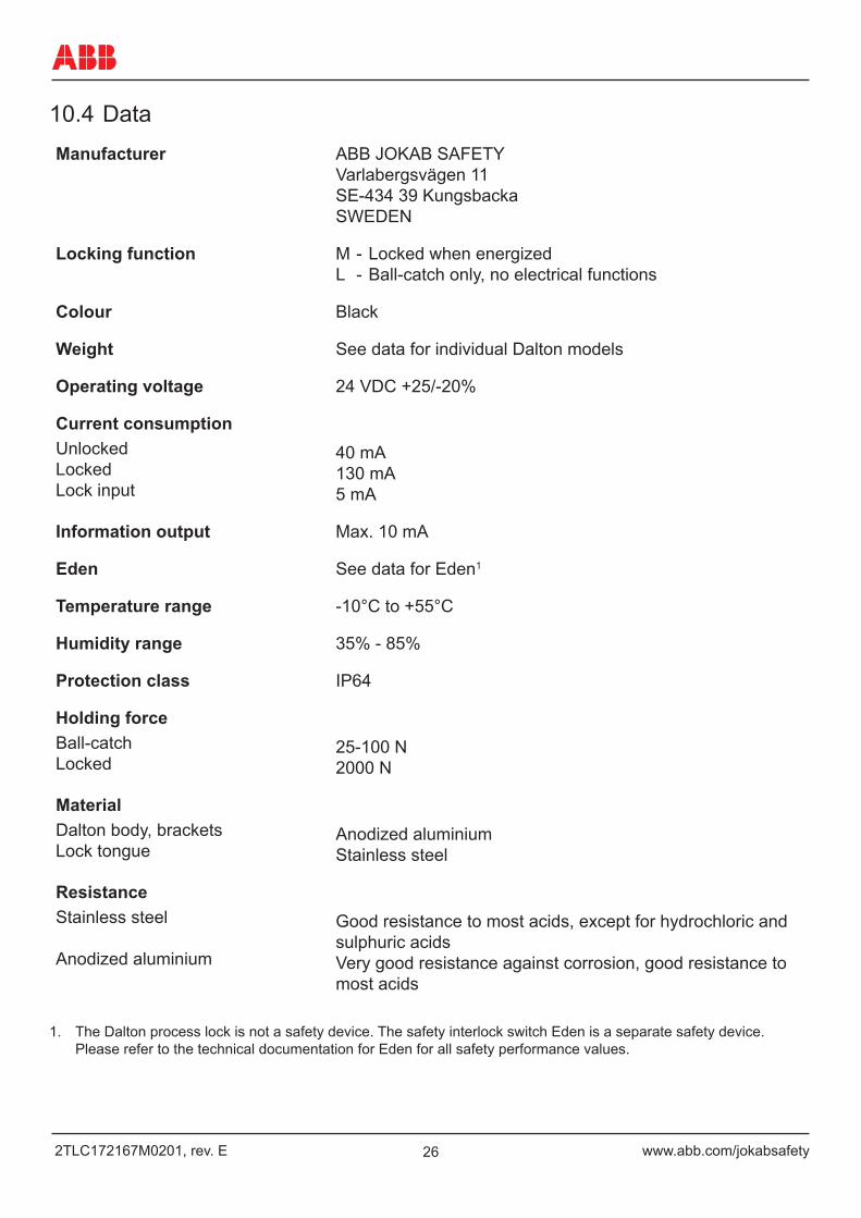
10.4 DataManufacturer ABB JOKAB SAFETY
Varlabergsvägen 11 SE-434 39 Kungsbacka SWEDEN
Locking function M - Locked when energized L - Ball-catch only, no electrical functions
Colour Black
Weight See data for individual Dalton models
Operating voltage 24 VDC +25/-20%
Current consumptionUnlocked Locked Lock input
40 mA 130 mA 5 mA
Information output Max. 10 mA
Eden See data for Eden1
Temperature range -10°C to +55°C
Humidity range 35% - 85%
Protection class IP64
Holding forceBall-catch Locked
25-100 N 2000 N
MaterialDalton body, brackets Lock tongue
Anodized aluminium Stainless steel
ResistanceStainless steel Anodized aluminium
Good resistance to most acids, except for hydrochloric and sulphuric acids Very good resistance against corrosion, good resistance to most acids
1. The Dalton process lock is not a safety device. The safety interlock switch Eden is a separate safety device. Please refer to the technical documentation for Eden for all safety performance values.
27www.abb.com/jokabsafety 2TLC172167M0201, rev. E
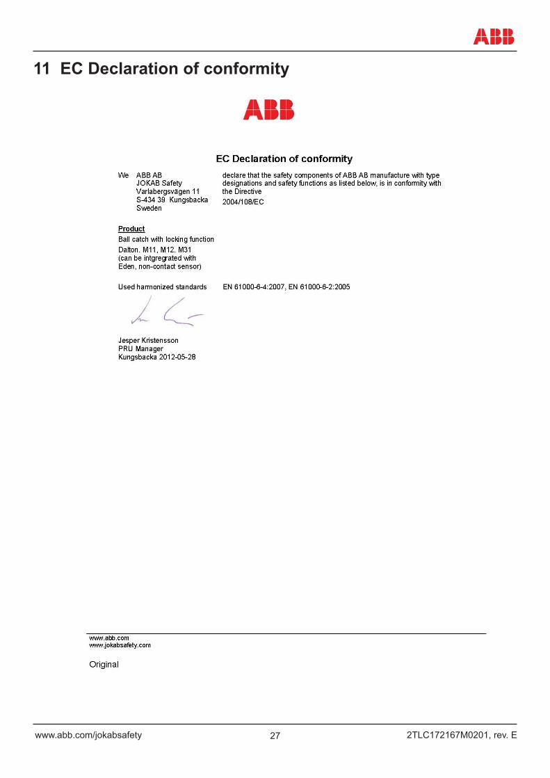
11 EC Declaration of conformity