Embed Size (px)
Citation preview
VFD for Centrifugal Chillers
DWSC/DWDC 063, 079, 087, 100, 113, 126
Original instructions
Installation, Operation and Maintenance Manual DEIMAC00904-14EU

2
ATTENTION
This Manual is a technical aid but does not represent a binding offer for Daikin. Daikin has drawn up this Manual to the best of its knowledge. The content cannot be held as explicitly or implicitly guaranteed as complete, precise or reliable. All data and specifications contained herein may be modified without notice. The data communicated at the moment of the order shall hold firm. Daikin shall assume no liability whatsoever for any direct or indirect damage, in the widest sense of the term, ensuing from or connected with the use and/or interpretation of this Manual. The entire content is protected by Daikin copyright.
WARNING
Before starting the installation of the unit, please read this manual carefully. Starting up the unit is absolutely forbidden if all instructions contained in this manual are not clear.
Key to symbols
Important note: failure to respect the instruction can damage the unit or compromise operation
Note regarding safety in general or respect of laws and regulations
Note regarding electrical safety

3
Table of Contents
General Information .............................................................................. 5 Purpose of the manual ............................................................................................... 5 Acceptance of the Product ......................................................................................... 5 Checks .......................................................................................................................... 5
Nomenclature .......................................................................................... 6
Introduction ............................................................................................ 7
VFDs and Distortion .............................................................................. 7 VFD Line Harmonics ................................................................................................... 7 EMI and RFI Filter ....................................................................................................... 7
Specifications .......................................................................................... 9 Standard Features ....................................................................................................... 9
Options .................................................................................................... 9 Harmonic Filter .......................................................................................................... 10 Top / Bottom In/Out Cable Entry ............................................................................... 9 Factory Mount .............................................................................................................. 9 Amp/Volt Meter ............................................................................................................ 9 Ground Fault Relay ..................................................................................................... 9 Extended Voltage Versions (340V up to 690V) ....................................................... 9
Technical Data ...................................................................................... 11
VFD Dimensional Drawings ................................................................ 12 Storage ........................................................................................................................ 15 Operation .................................................................................................................... 15
Mechanical Installation ........................................................................ 16 Shipping ...................................................................................................................... 16 Responsibility ............................................................................................................. 16 Safety .......................................................................................................................... 16 Cabinet Handling and Lifting .................................................................................... 17 Positioning and assembly ........................................................................................ 17 Minimum space requirements ................................................................................. 17 Installation of Units .................................................................................................... 18
Electrical Installation ........................................................................... 19 Field Wiring Diagram ................................................................................................ 20 Power Wiring .............................................................................................................. 21 VFD Terminals ........................................................................................................... 22 IT Mains ...................................................................................................................... 22
Operation .............................................................................................. 23 Start-up........................................................................................................................ 23 Operator Panel .......................................................................................................... 24 Alarms ......................................................................................................................... 31 Drive Commissioning ................................................................................................ 32
Maintenance .......................................................................................... 38 Safety Instructions ..................................................................................................... 38
Passive Harmonic filter Panels ............................................................ 42
Reference Documentation .................................................................... 42
Technical Characteristics ..................................................................... 43

4
Terms of Supply .................................................................................... 43
Handling and Transport ...................................................................... 43 Pallet Truck ................................................................................................................. 43 Forklift.......................................................................................................................... 44 Crane or Bridge Crane ............................................................................................ 44
Assembly ............................................................................................... 44 Systems with one harmonic filter ............................................................................ 44 Systems with two harmonic filters ........................................................................... 45
Wiring .................................................................................................... 46 Systems with one harmonic filter ............................................................................ 47 Systems with two harmonic filter ............................................................................. 47
Cables Cross Sections ........................................................................... 48
Low harmonic filter ............................................................................. 49
5
General Information
ATTENTION
The machines described in this manual represent a valuable investment. Maximum care should be taken to ensure
correct installation and to maintain them in good running order.
Correct maintenance of the unit is indispensable for its safety and reliability. Manufacturer’s service centres are the
only having adequate technical skill for maintenance.
ATTENTION
This manual describes the features and standard procedures for the complete series of units.
All the units are delivered together with electrical diagrams and inverter manuals.
WIRING DIAGRAMS AND INVERTER MANUALS MUST BE CONSIDERED ESSENTIAL PARTS OF THIS
MANUAL
In the case of discrepancy between this manual and the wiring diagram or the dimensional diagram, the latter two
documents must be considered valid.
Purpose of the manual
The purpose of this manual is to allow the installer and the qualified operator to carry out all operations necessary to ensure correct installation and maintenance of the machine without running the risk of harm to persons, animals or property. The manual is an important documentary aid to qualified persons, but cannot substitute them. All actions must be carried out by trained and qualified personnel, in compliance with local laws and regulations. NTION Acceptance of the Product
When the VFD is delivered to the place of installation, it must immediately be inspected for damage. All components described in the delivery note must be carefully inspected and checked; any damage must be reported to the carrier. Before unloading the machine, check that the model and the voltage shown on the identity plate correspond to your order. The manufacturer shall accept no liability for any damage which comes to light after acceptance of the machine. Checks
For your own protection in case the machine is incomplete (missing parts) or has been damaged during transport, carry out the following checks upon receipt of the machine:
a) Before accepting the VFD, check every single component of the supply. Check for any damage. b) If the VFD has been damaged, do not remove the damaged parts. A series of pictures can help to verify
responsibility. c) Immediately report the extent of the damage to the transport company and request them to inspect the
machine. d) Immediately inform the dealer of the extent of the damage to allow the latter to arrange for the necessary
repairs. Under no circumstances must the damage be repaired before being inspected by a representative of the transport company.
6
Nomenclature
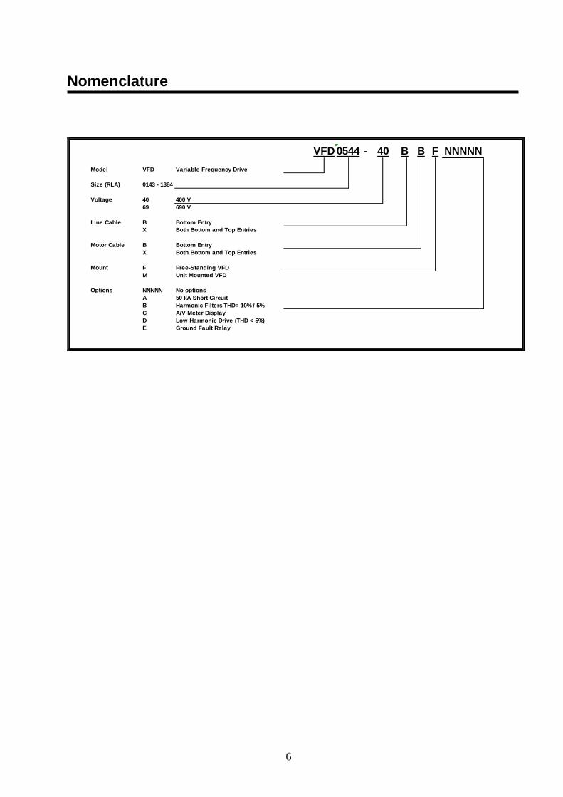
NNNNN
Model VFD Variable Frequency Drive
Size (RLA) 0143 - 1384
Voltage 40 400 V
69 690 V
Line Cable B Bottom Entry
X Both Bottom and Top Entries
Motor Cable B Bottom Entry
X Both Bottom and Top Entries
Mount F Free-Standing VFD
M Unit Mounted VFD
Options NNNNN No options
A 50 kA Short Circuit
B Harmonic Filters THD= 10% / 5%
C A/V Meter Display
D Low Harmonic Drive (THD < 5%)
E Ground Fault Relay
FB BVFD 0544 - 40
7
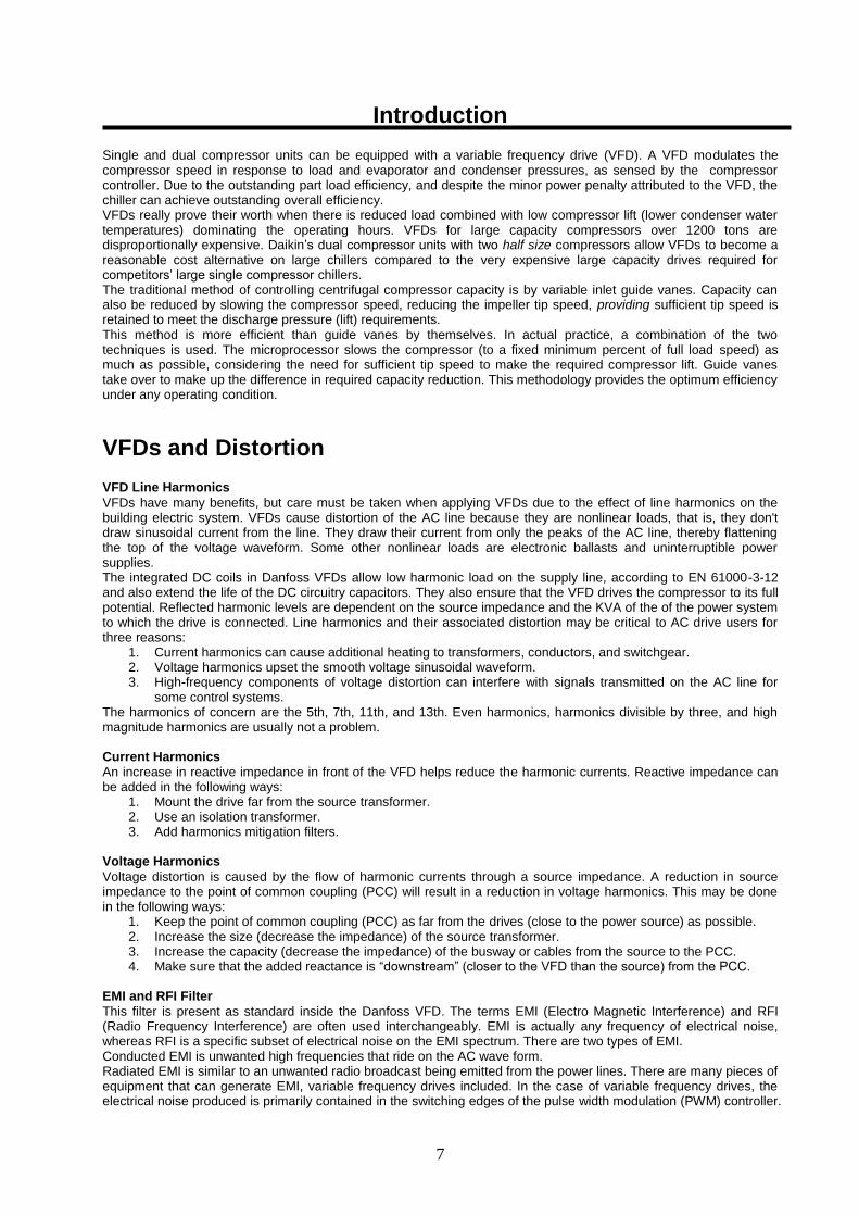
Introduction Single and dual compressor units can be equipped with a variable frequency drive (VFD). A VFD modulates the compressor speed in response to load and evaporator and condenser pressures, as sensed by the compressor controller. Due to the outstanding part load efficiency, and despite the minor power penalty attributed to the VFD, the chiller can achieve outstanding overall efficiency. VFDs really prove their worth when there is reduced load combined with low compressor lift (lower condenser water temperatures) dominating the operating hours. VFDs for large capacity compressors over 1200 tons are disproportionally expensive. Daikin’s dual compressor units with two half size compressors allow VFDs to become a reasonable cost alternative on large chillers compared to the very expensive large capacity drives required for competitors’ large single compressor chillers. The traditional method of controlling centrifugal compressor capacity is by variable inlet guide vanes. Capacity can also be reduced by slowing the compressor speed, reducing the impeller tip speed, providing sufficient tip speed is retained to meet the discharge pressure (lift) requirements. This method is more efficient than guide vanes by themselves. In actual practice, a combination of the two techniques is used. The microprocessor slows the compressor (to a fixed minimum percent of full load speed) as much as possible, considering the need for sufficient tip speed to make the required compressor lift. Guide vanes take over to make up the difference in required capacity reduction. This methodology provides the optimum efficiency under any operating condition.
VFDs and Distortion VFD Line Harmonics
VFDs have many benefits, but care must be taken when applying VFDs due to the effect of line harmonics on the building electric system. VFDs cause distortion of the AC line because they are nonlinear loads, that is, they don't draw sinusoidal current from the line. They draw their current from only the peaks of the AC line, thereby flattening the top of the voltage waveform. Some other nonlinear loads are electronic ballasts and uninterruptible power supplies. The integrated DC coils in Danfoss VFDs allow low harmonic load on the supply line, according to EN 61000-3-12 and also extend the life of the DC circuitry capacitors. They also ensure that the VFD drives the compressor to its full potential. Reflected harmonic levels are dependent on the source impedance and the KVA of the of the power system to which the drive is connected. Line harmonics and their associated distortion may be critical to AC drive users for three reasons:
1. Current harmonics can cause additional heating to transformers, conductors, and switchgear. 2. Voltage harmonics upset the smooth voltage sinusoidal waveform. 3. High-frequency components of voltage distortion can interfere with signals transmitted on the AC line for
some control systems. The harmonics of concern are the 5th, 7th, 11th, and 13th. Even harmonics, harmonics divisible by three, and high magnitude harmonics are usually not a problem. Current Harmonics
An increase in reactive impedance in front of the VFD helps reduce the harmonic currents. Reactive impedance can be added in the following ways:
1. Mount the drive far from the source transformer. 2. Use an isolation transformer. 3. Add harmonics mitigation filters.
Voltage Harmonics
Voltage distortion is caused by the flow of harmonic currents through a source impedance. A reduction in source impedance to the point of common coupling (PCC) will result in a reduction in voltage harmonics. This may be done in the following ways:
1. Keep the point of common coupling (PCC) as far from the drives (close to the power source) as possible. 2. Increase the size (decrease the impedance) of the source transformer. 3. Increase the capacity (decrease the impedance) of the busway or cables from the source to the PCC. 4. Make sure that the added reactance is “downstream” (closer to the VFD than the source) from the PCC.
EMI and RFI Filter
This filter is present as standard inside the Danfoss VFD. The terms EMI (Electro Magnetic Interference) and RFI (Radio Frequency Interference) are often used interchangeably. EMI is actually any frequency of electrical noise, whereas RFI is a specific subset of electrical noise on the EMI spectrum. There are two types of EMI. Conducted EMI is unwanted high frequencies that ride on the AC wave form. Radiated EMI is similar to an unwanted radio broadcast being emitted from the power lines. There are many pieces of equipment that can generate EMI, variable frequency drives included. In the case of variable frequency drives, the electrical noise produced is primarily contained in the switching edges of the pulse width modulation (PWM) controller.

8
As the technology of drives evolves, switching frequencies increase. These increases also increase the effective edge frequencies produced, thereby increasing the amount of electrical noise. The power line noise emissions associated with variable frequency and variable speed drives can cause disturbances in nearby equipment. Typical disturbances include:
Dimmer and ballast instability
Lighting disturbances such as flashing
Poor radio reception
Poor television reception
Instability of control systems
Flow meter totalizing
Flow metering fluctuation
Computer system failures including the loss of data
Thermostat control problems
Radar disruption
Sonar disruption The combined action of RFI filters and harmonic filters integrated into Danfoss VFD, allow to keep "clean" mains supply. The drive conforms to EN 61800-3 EMC product without additional external components and complies with the EMC guidelines 2004/108/EC, providing superior performances. Harmonic inductances integrated as standard, minimize harmonic distortion of the current absorbed by ensuring operations in compliance with the limits imposed by standard EN 61000-3-12.
9
Specifications
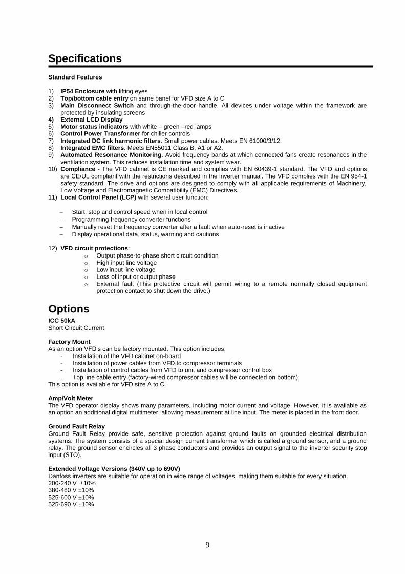
Standard Features 1) IP54 Enclosure with lifting eyes 2) Top/bottom cable entry on same panel for VFD size A to C 3) Main Disconnect Switch and through-the-door handle. All devices under voltage within the framework are
protected by insulating screens 4) External LCD Display 5) Motor status indicators with white – green –red lamps 6) Control Power Transformer for chiller controls 7) Integrated DC link harmonic filters. Small power cables. Meets EN 61000/3/12. 8) Integrated EMC filters. Meets EN55011 Class B, A1 or A2. 9) Automated Resonance Monitoring. Avoid frequency bands at which connected fans create resonances in the
ventilation system. This reduces installation time and system wear. 10) Compliance - The VFD cabinet is CE marked and complies with EN 60439-1 standard. The VFD and options
are CE/UL compliant with the restrictions described in the inverter manual. The VFD complies with the EN 954-1 safety standard. The drive and options are designed to comply with all applicable requirements of Machinery, Low Voltage and Electromagnetic Compatibility (EMC) Directives.
11) Local Control Panel (LCP) with several user function:
Start, stop and control speed when in local control
Programming frequency converter functions
Manually reset the frequency converter after a fault when auto-reset is inactive
Display operational data, status, warning and cautions
12) VFD circuit protections:
o Output phase-to-phase short circuit condition o High input line voltage o Low input line voltage o Loss of input or output phase o External fault (This protective circuit will permit wiring to a remote normally closed equipment
protection contact to shut down the drive.)
Options ICC 50kA
Short Circuit Current Factory Mount
As an option VFD’s can be factory mounted. This option includes: - Installation of the VFD cabinet on-board - Installation of power cables from VFD to compressor terminals - Installation of control cables from VFD to unit and compressor control box - Top line cable entry (factory-wired compressor cables will be connected on bottom)
This option is available for VFD size A to C. Amp/Volt Meter
The VFD operator display shows many parameters, including motor current and voltage. However, it is available as an option an additional digital multimeter, allowing measurement at line input. The meter is placed in the front door. Ground Fault Relay
Ground Fault Relay provide safe, sensitive protection against ground faults on grounded electrical distribution systems. The system consists of a special design current transformer which is called a ground sensor, and a ground relay. The ground sensor encircles all 3 phase conductors and provides an output signal to the inverter security stop input (STO). Extended Voltage Versions (340V up to 690V)
Danfoss inverters are suitable for operation in wide range of voltages, making them suitable for every situation. 200-240 V ±10% 380-480 V ±10% 525-600 V ±10% 525-690 V ±10%
10
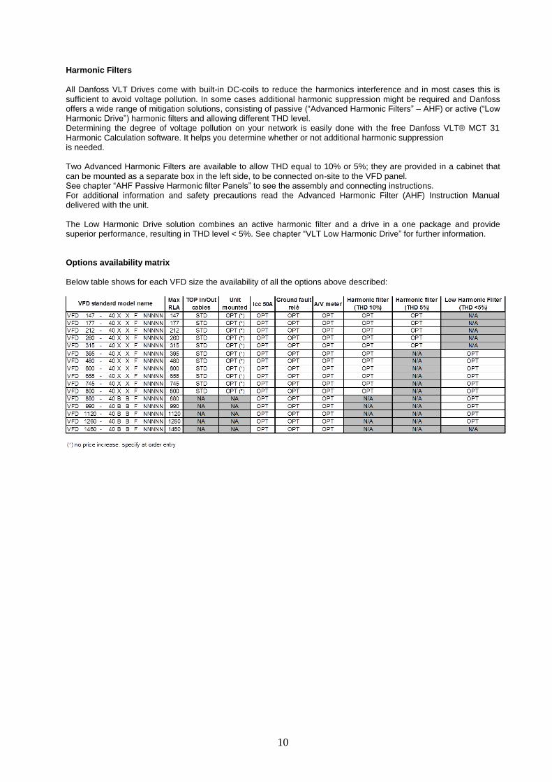
Harmonic Filters
All Danfoss VLT Drives come with built-in DC-coils to reduce the harmonics interference and in most cases this is sufficient to avoid voltage pollution. In some cases additional harmonic suppression might be required and Danfoss offers a wide range of mitigation solutions, consisting of passive (“Advanced Harmonic Filters” – AHF) or active (“Low Harmonic Drive”) harmonic filters and allowing different THD level. Determining the degree of voltage pollution on your network is easily done with the free Danfoss VLT® MCT 31 Harmonic Calculation software. It helps you determine whether or not additional harmonic suppression is needed. Two Advanced Harmonic Filters are available to allow THD equal to 10% or 5%; they are provided in a cabinet that can be mounted as a separate box in the left side, to be connected on-site to the VFD panel. See chapter “AHF Passive Harmonic filter Panels” to see the assembly and connecting instructions. For additional information and safety precautions read the Advanced Harmonic Filter (AHF) Instruction Manual delivered with the unit. The Low Harmonic Drive solution combines an active harmonic filter and a drive in a one package and provide superior performance, resulting in THD level < 5%. See chapter “VLT Low Harmonic Drive” for further information. Options availability matrix
Below table shows for each VFD size the availability of all the options above described:
11
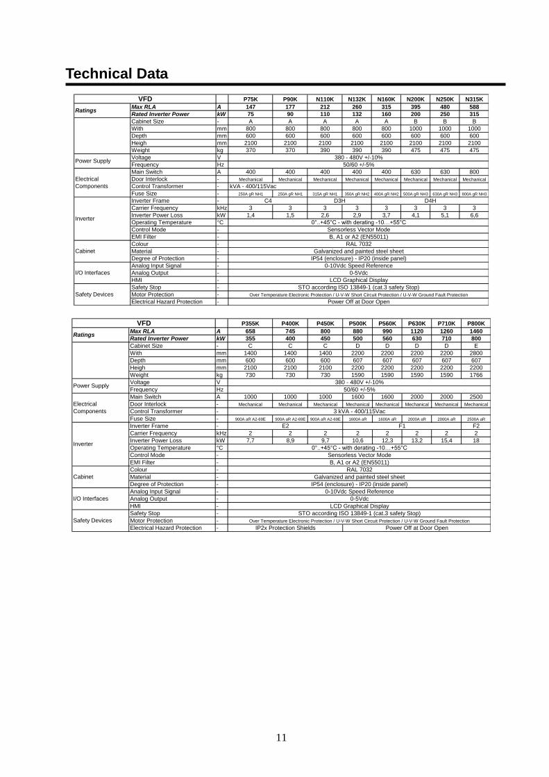
Technical Data
P75K P90K N110K N132K N160K N200K N250K N315K
Max RLA A 147 177 212 260 315 395 480 588
Rated Inverter Power kW 75 90 110 132 160 200 250 315
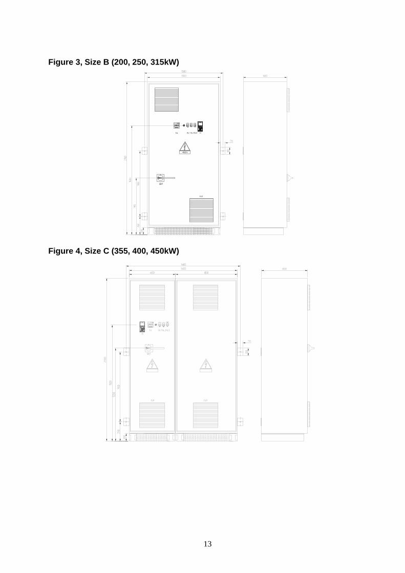
Cabinet Size - A A A A A B B B
With mm 800 800 800 800 800 1000 1000 1000
Depth mm 600 600 600 600 600 600 600 600
Heigh mm 2100 2100 2100 2100 2100 2100 2100 2100
Weight kg 370 370 390 390 390 475 475 475
Voltage V
Frequency Hz
Main Switch A 400 400 400 400 400 630 630 800
Door Interlock - Mechanical Mechanical Mechanical Mechanical Mechanical Mechanical Mechanical Mechanical
Control Transformer - 3 kVA - 400/115Vac
Fuse Size - 250A gR NH1 250A gR NH1 315A gR NH1 350A gR NH2 400A gR NH2 500A gR NH3 630A gR NH3 800A gR NH3
Inverter Frame -
Carrier Frequency kHz 3 3 3 3 3 3 3 3
Inverter Power Loss kW 1,4 1,5 2,6 2,9 3,7 4,1 5,1 6,6
Operating Temperature °C
Control Mode -
EMI Filter -
Colour -
Material -
Degree of Protection -
Analog Input Signal -
Analog Output -
HMI -
Safety Stop -
Motor Protection -
Electrical Hazard Protection -
0-5Vdc
LCD Graphical Display
STO according ISO 13849-1 (cat.3 safety Stop)
Over Temperature Electronic Protection / U-V-W Short Circuit Protection / U-V-W Ground Fault Protection
RAL 7032
Galvanized and painted steel sheet
IP54 (enclosure) - IP20 (inside panel)
0-10Vdc Speed Reference
Safety Devices
Power Off at Door Open
I/O Interfaces
Cabinet
0°..+45°C - with derating -10…+55°C
Sensorless Vector Mode
Inverter
C4 D3H D4H
B, A1 or A2 (EN55011)
Electrical
Components
380 - 480V +/-10%
50/60 +/-5%
VFD
Ratings
Power Supply
P355K P400K P450K P500K P560K P630K P710K P800K
Max RLA A 658 745 800 880 990 1120 1260 1460
Rated Inverter Power kW 355 400 450 500 560 630 710 800
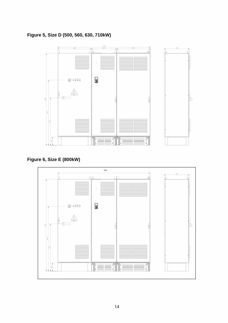
Cabinet Size - C C C D D D D E
With mm 1400 1400 1400 2200 2200 2200 2200 2800
Depth mm 600 600 600 607 607 607 607 607
Heigh mm 2100 2100 2100 2200 2200 2200 2200 2200
Weight kg 730 730 730 1590 1590 1590 1590 1766
Voltage V
Frequency Hz
Main Switch A 1000 1000 1000 1600 1600 2000 2000 2500
Door Interlock - Mechanical Mechanical Mechanical Mechanical Mechanical Mechanical Mechanical Mechanical
Control Transformer -
Fuse Size - 900A aR A2-69E 900A aR A2-69E 900A aR A2-69E 1600A aR 1600A aR 2000A aR 2000A aR 2500A aR
Inverter Frame - F2
Carrier Frequency kHz 2 2 2 2 2 2 2 2
Inverter Power Loss kW 7,7 8,9 9,7 10,6 12,3 13,2 15,4 18
Operating Temperature °C
Control Mode -
EMI Filter -
Colour -
Material -
Degree of Protection -
Analog Input Signal -
Analog Output -
HMI -
Safety Stop -
Motor Protection -
Electrical Hazard Protection -
Over Temperature Electronic Protection / U-V-W Short Circuit Protection / U-V-W Ground Fault Protection
Galvanized and painted steel sheet
IP54 (enclosure) - IP20 (inside panel)
0-10Vdc Speed Reference
0-5Vdc
0°..+45°C - with derating -10…+55°C
Sensorless Vector Mode
B, A1 or A2 (EN55011)
RAL 7032
380 - 480V +/-10%
50/60 +/-5%
3 kVA - 400/115Vac
F1E2
LCD Graphical Display
STO according ISO 13849-1 (cat.3 safety Stop)
Power Off at Door OpenIP2x Protection Shields
Safety Devices
I/O Interfaces
VFD
Ratings
Power Supply
Electrical
Components
Inverter
Cabinet
12
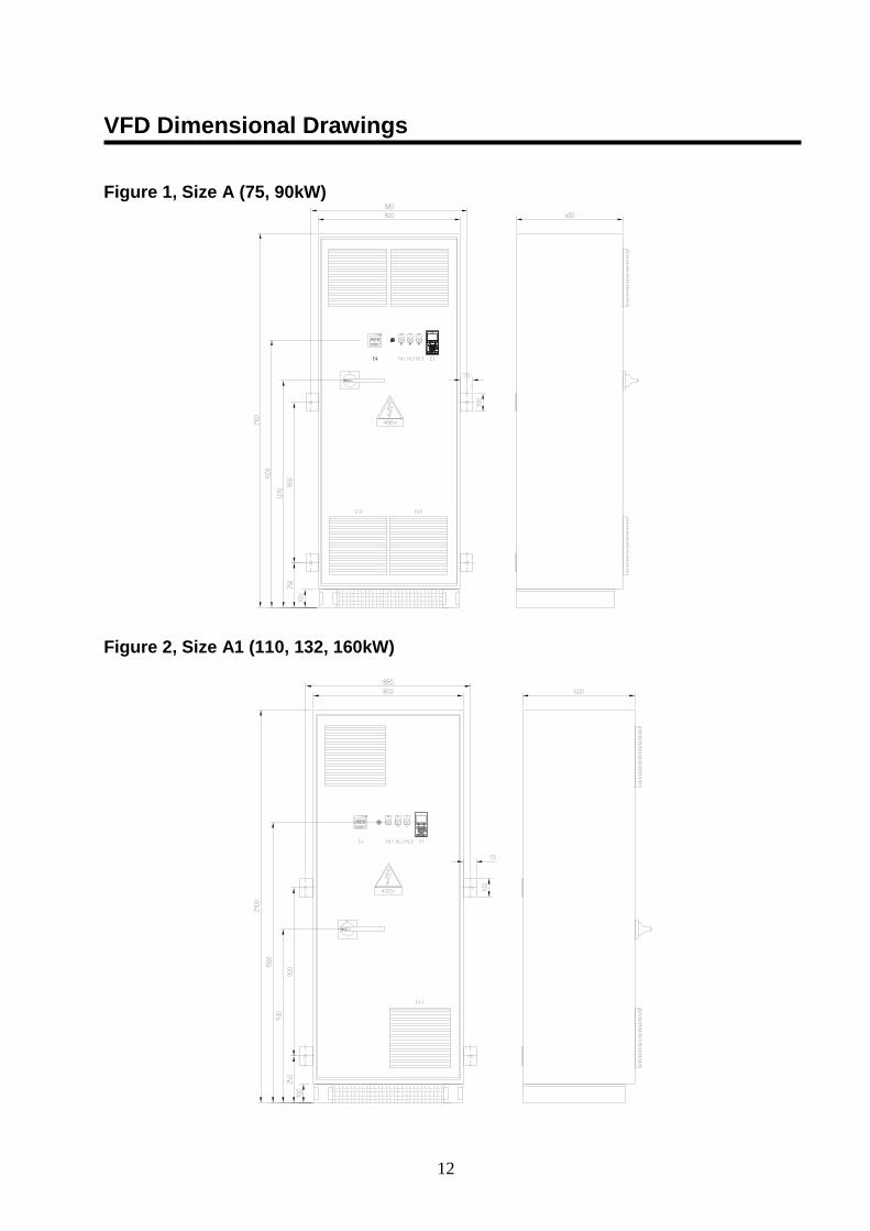
VFD Dimensional Drawings
Figure 1, Size A (75, 90kW)
Figure 2, Size A1 (110, 132, 160kW)
13
Figure 3, Size B (200, 250, 315kW)
Figure 4, Size C (355, 400, 450kW)
14
Figure 5, Size D (500, 560, 630, 710kW)
Figure 6, Size E (800kW)
provvisorio
2800
15
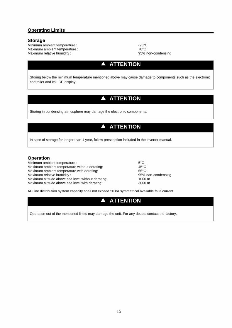
Operating Limits
Storage Minimum ambient temperature : -25°C Maximum ambient temperature : 70°C Maximum relative humidity : 95% non-condensing
ATTENTION
Storing below the minimum temperature mentioned above may cause damage to components such as the electronic
controller and its LCD display.
ATTENTION
Storing in condensing atmosphere may damage the electronic components.
ATTENTION
In case of storage for longer than 1 year, follow prescription included in the inverter manual.
Operation Minimum ambient temperature : 5°C Maximum ambient temperature without derating: 45°C Maximum ambient temperature with derating: 55°C Maximum relative humidity : 95% non-condensing Maximum altitude above sea level without derating: 1000 m Maximum altitude above sea level with derating: 3000 m AC line distribution system capacity shall not exceed 50 kA symmetrical available fault current.
ATTENTION
Operation out of the mentioned limits may damage the unit. For any doubts contact the factory.
16
Mechanical Installation
Shipping The stability and the absence of any kind of deformation of the unit during shipping must be ensured. If the machine is shipped with a wooden cross-plank on its base, this cross-plank must only be removed after the final destination has been reached.
Responsibility The manufacturer declines all present and future responsibility for any damage to persons, animals or things caused by negligence of operators failing to follow the installation and maintenance instructions in this Manual. All safety equipment must be regularly and periodically checked in accordance with this manual and with local laws and regulations regarding safety and environment protection. The rating plate specifies the serial number, the main operating data and the manufacturing year: they must always be provided for further information, especially when ordering spare parts.
Safety The machine must be securely fixed to the ground. It is essential to observe the following instructions:
The cabinet can only be lifted using the hoist points marked in yellow that are fixed to its base. These are the only points that can support the entire weight of the unit.
Do not allow unauthorised and/or unqualified personnel access to the machine.
It is forbidden to access electrical components without having opened the main switch and switched off the power supply.
It is forbidden to access electrical components without using an insulating platform. Do not access the electrical components if water and/or moisture are present.
Switch off the power supply, by opening the main switch, before servicing the VFD. Failure to observe this rule could result in serious personal injury.
In case of sudden stop of the unit, follow the instructions on the VLT Operating Instructions Manual which is part of
the on-board documentation delivered to the end user with this manual. It is recommended to perform installation and maintenance with other people. In case of accidental injury or unease, it is necessary to: - keep calm - press the alarm button if present in the installation site - move the injured person in a warm place far from the unit and in rest position - contact immediately emergency rescue personnel of the building or if the Health Emergency Service - wait without leaving the injured person alone until the rescue operators come - give all necessary information to the rescue operators
WARNING
Before carrying out any operation on the machine, please read carefully the instruction and operating manual.
Installation and maintenance must be carried out solely by qualified personnel that is familiar with provisions of law
and local regulations and has been trained properly or has experience with this type of equipment.

17
Cabinet Handling and Lifting Avoid bumping and/or jolting during unloading from the lorry and moving the machine. Do not push or pull the machine from any part other than the base frame. Block the machine from sliding inside the lorry in order to prevent damage to the panels and to the base frame. Avoid any part of the machine falling during unloading and/or moving, as this could cause serious damage. All units of the series are supplied with four lifting points. Only use these points for lifting the unit, as shown in figure 7.
Figure 7 – Lifting the unit
WARNING
Both the lifting ropes and the spacing bar and/or scales must be of sufficient size to support the machine safely. Please verify the unit’s weight on the machine’s nameplate. The weights shown in the “Technical data” tables refer to standard units.
WARNING
The machine must be lifted with the utmost attention and care. Avoid jolting when lifting and lift machine very slowly, keeping it perfectly level.
Positioning and assembly All units are produced for indoor installation. Outdoor installation should be avoided although the cabinet is IP54 rated. The cabinet must be installed vertically on a robust and perfectly level foundation. To avoid heat sink overheat and/or damage on the installation site, the following precautions and instructions must be followed:
Avoid air flow recirculation
Make sure that there are no obstacles to hamper air flow.
Air must circulate freely to ensure proper intake and expulsion.
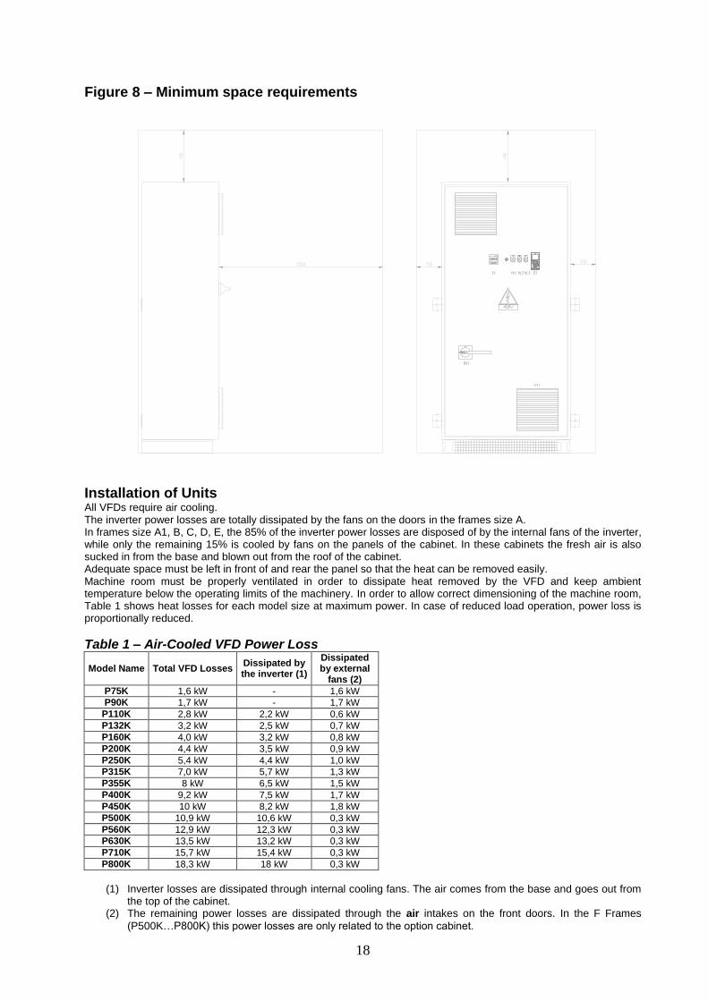
Minimum space requirements It is fundamental to respect minimum distances on all units, in order to ensure optimum ventilation for the electrical panel and to allow easy maintenance. All cabinets have ventilation fans placed in the front door (horizontal air flow) for to keep the electrical panel cold. The air passages must remain absolutely free of ostructions to ensure maximum cooling efficiency. Air filters must be periodically checked and cleaned. A minimum space on front of the panel must be left in order to allow easy maintenance and repair of cooling fans. Figure 8 shows the minimum space required. Should the machine be installed without observing the recommended minimum distances from walls and/or vertical obstacles, there could be a combination of warm air recirculation and/or insufficient supply to the inverter air-cooled heatsink which could overheat the VFD.
18
Figure 8 – Minimum space requirements
Installation of Units All VFDs require air cooling. The inverter power losses are totally dissipated by the fans on the doors in the frames size A. In frames size A1, B, C, D, E, the 85% of the inverter power losses are disposed of by the internal fans of the inverter, while only the remaining 15% is cooled by fans on the panels of the cabinet. In these cabinets the fresh air is also sucked in from the base and blown out from the roof of the cabinet. Adequate space must be left in front of and rear the panel so that the heat can be removed easily. Machine room must be properly ventilated in order to dissipate heat removed by the VFD and keep ambient temperature below the operating limits of the machinery. In order to allow correct dimensioning of the machine room, Table 1 shows heat losses for each model size at maximum power. In case of reduced load operation, power loss is proportionally reduced.
Table 1 – Air-Cooled VFD Power Loss
Model Name Total VFD Losses Dissipated by the inverter (1)
Dissipated by external
fans (2)
P75K 1,6 kW - 1,6 kW
P90K 1,7 kW - 1,7 kW
P110K 2,8 kW 2,2 kW 0,6 kW
P132K 3,2 kW 2,5 kW 0,7 kW
P160K 4,0 kW 3,2 kW 0,8 kW
P200K 4,4 kW 3,5 kW 0,9 kW
P250K 5,4 kW 4,4 kW 1,0 kW
P315K 7,0 kW 5,7 kW 1,3 kW
P355K 8 kW 6,5 kW 1,5 kW
P400K 9,2 kW 7,5 kW 1,7 kW
P450K 10 kW 8,2 kW 1,8 kW
P500K 10,9 kW 10,6 kW 0,3 kW
P560K 12,9 kW 12,3 kW 0,3 kW
P630K 13,5 kW 13,2 kW 0,3 kW
P710K 15,7 kW 15,4 kW 0,3 kW
P800K 18,3 kW 18 kW 0,3 kW
(1) Inverter losses are dissipated through internal cooling fans. The air comes from the base and goes out from
the top of the cabinet. (2) The remaining power losses are dissipated through the air intakes on the front doors. In the F Frames
(P500K…P800K) this power losses are only related to the option cabinet.
19
Electrical Installation
ATTENTION
All electrical connections to the machine must be carried out in compliance national codes and regulations. All installation, management and maintenance activities must be carried out by qualified personnel. Refer to the specific wiring diagram for the machine that you have purchased and which was sent with the unit. Should the wiring diagram not appear on the machine or should it have been lost, please contact your nearest manufacturer office, who will send you a copy.
ATTENTION
Use copper conductors only. Failure to use copper conductors could result in overheating or corrosion at connection points and could damage the unit. To avoid interference, all control wires must be connected separately from the power cables. Use different electrical passage ducts for this purpose.
CAUTION
Before any installation and connection work, the system must be switched off and secured. After switching off the unit, the intermediate circuit capacitors of the inverter are still charged with high voltage for a short period of time. The unit can be worked on again after it has been switched of for 5 minutes.
CAUTION
Before taking any action, switch off the main switch to cut off electricity to the machine. When the machine is off but the disconnecting switch is in the closed position, unused circuits are always live. Never open the terminal board box of the compressors unless the main switch of the machine has been switched off.
ATTENTION
Short-circuit withstand current is 50 kA. Check the actual short-circuit value at VFD input terminals and contact factory in case a higher short-circuit withstand current is needed.
20
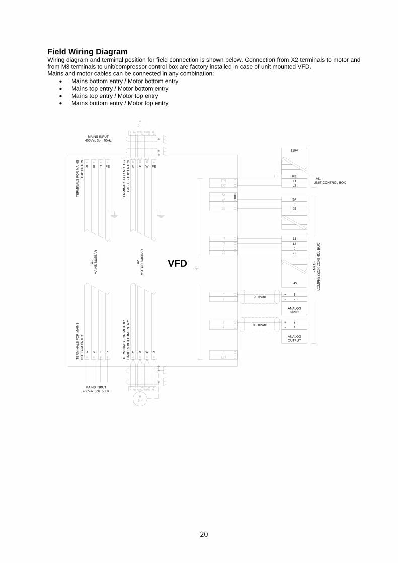
Field Wiring Diagram Wiring diagram and terminal position for field connection is shown below. Connection from X2 terminals to motor and from M3 terminals to unit/compressor control box are factory installed in case of unit mounted VFD. Mains and motor cables can be connected in any combination:
Mains bottom entry / Motor bottom entry
Mains top entry / Motor bottom entry
Mains top entry / Motor top entry
Mains bottom entry / Motor top entry
PE
L1
L2
5A
5
25
11
12
6
22
24V
110V
1
2
ANALOG
INPUT
3
4
ANALOG
OUTPUT
- M1 -
UNIT CONTROL BOX
- M
2A
-
CO
MP
RE
SS
OR
CO
NT
RO
L B
OX
- X
1 -
MA
INS
BU
SB
AR
R S T PE
R S T PE
TE
RM
INA
LS
FO
R M
AIN
S
TO
P E
NT
RY
TE
RM
INA
LS
FO
R M
AIN
S
BO
TT
OM
EN
TR
Y
- X
2 -
MO
TO
R B
US
BA
R
U V W PE
U V W PE
TE
RM
INA
LS
FO
R M
OT
OR
CA
BL
ES
TO
P E
NT
RY
TE
RM
INA
LS
FO
R M
OT
OR
CA
BL
ES
BO
TT
OM
EN
TR
Y
VFD
0 - 5Vdc
0 - 10Vdc+
-
-
+
MAINS INPUT
400Vac 3ph 50Hz
MAINS INPUT
400Vac 3ph 50Hz
21
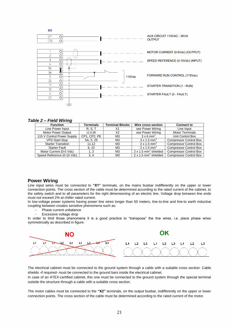
Table 2 – Field Wiring Function Terminals Terminal Blocks Wire cross-section Connect to
Line Power Input R, S, T X1 see Power Wiring Line Input
Motor Power Output U,V,W X2 see Power Wiring Motor Terminals
115 V Control Power Supply CP1, CP2, PE M3 3 x 6 mm2
Unit Control Box
VFD Start-Stop 5A, 5, 25 M3 3 x 1.5 mm2
Compressor Control Box
Starter Transition 11,12 M3 2 x 1.5 mm2
Compressor Control Box
Starter Fault 6, 22 M3 2 x 1.5 mm2 Compressor Control Box
Motor Current (0-5 Vdc) 1, 2 M3 2 x 1.5 mm2 shielded Compressor Control Box
Speed Reference (0-10 Vdc) 3, 4 M3 2 x 1.5 mm2 shielded
Compressor Control Box
Power Wiring Line input wires must be connected to “X1” terminals, on the mains busbar indifferently on the upper or lower
connection points. The cross section of the cable must be determined according to the rated current of the cabinet, to the safety switch and to all parameters for the right dimensioning of an electric line. Voltage drop between line ends must not exceed 2% at chiller rated current. In low-voltage power systems having power line wires longer than 50 meters, line-to-line and line-to earth inductive coupling between creates sensitive phenomena such as:
Phase current unbalance
Excessive voltage drop In order to limit those phenomena it is a good practice to “transpose” the line wires, i.e. place phase wires symmetrically as described in figure.
The electrical cabinet must be connected to the ground system through a cable with a suitable cross section. Cable
shields -if required- must be connected to the ground bars inside the electrical cabinet.
In case of an ATEX-certified cabinet, this one must be connected to the ground system through the special terminal
outside the structure through a cable with a suitable cross section.
The motor cables must be connected to the “X2” terminals, on the output busbar, indifferently on the upper or lower
connection points. The cross section of the cable must be determined according to the rated current of the motor.
22
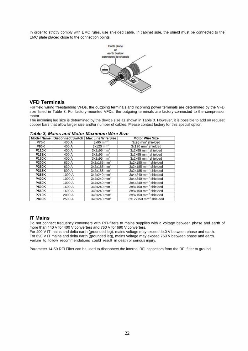
In order to strictly comply with EMC rules, use shielded cable. In cabinet side, the shield must be connected to the
EMC plate placed close to the connection points.
VFD Terminals For field wiring freestanding VFDs, the outgoing terminals and incoming power terminals are determined by the VFD size listed in Table 3. For factory-mounted VFDs, the outgoing terminals are factory-connected to the compressor motor. The incoming lug size is determined by the device size as shown in Table 3. However, it is possible to add on request copper bars that allow larger size and/or number of cables. Please contact factory for this special option.
Table 3, Mains and Motor Maximum Wire Size Model Name Disconnect Switch Max Line Wire Size Motor Wire Size
P75K 400 A 3x95 mm2
3x95 mm2 shielded
P90K 400 A 3x120 mm2 3x120 mm
2 shielded
P110K 400 A 3x2x95 mm2
3x2x95 mm2 shielded
P132K 400 A 3x2x95 mm2 3x2x95 mm
2 shielded
P160K 400 A 3x2x95 mm2 3x2x95 mm
2 shielded
P200K 630 A 3x2x185 mm2 3x2x185 mm
2 shielded
P250K 630 A 3x2x185 mm2 3x2x185 mm
2 shielded
P315K 800 A 3x2x185 mm2 3x2x185 mm
2 shielded
P355K 1000 A 3x4x240 mm2 3x4x240 mm
2 shielded
P400K 1000 A 3x4x240 mm2 3x4x240 mm
2 shielded
P450K 1000 A 3x4x240 mm2 3x4x240 mm
2 shielded
P500K 1600 A 3x8x240 mm2 3x8x150 mm
2 shielded
P560K 1600 A 3x8x240 mm2 3x8x150 mm
2 shielded
P710K 2000 A 3x8x240 mm2 3x8x150 mm
2 shielded
P800K 2500 A 3x8x240 mm2 3x12x150 mm
2 shielded
IT Mains Do not connect frequency converters with RFI-filters to mains supplies with a voltage between phase and earth of more than 440 V for 400 V converters and 760 V for 690 V converters. For 400 V IT mains and delta earth (grounded leg), mains voltage may exceed 440 V between phase and earth. For 690 V IT mains and delta earth (grounded leg), mains voltage may exceed 760 V between phase and earth. Failure to follow recommendations could result in death or serious injury. Parameter 14-50 RFI Filter can be used to disconnect the internal RFI capacitors from the RFI filter to ground.
23
Operation
Start-up
ATTENTION
It is extremely important to fulfil the following procedure. Avoid to fulfil these instructions may lead to damages and invalidate warranty.
Before starting up the electrical cabinet the following steps must be checked an carried out: - Check the working data by comparing the data on the rating plate with the order and the data of the unit -for
example working pressure and frequency- to be sure they match. - The voltage supply must match the voltage on the rating plate. The electrical cabinet must be connected
according to the electrical drawings included to the unit. - Check the connection of the electrical cabinet to the existing ground system. In particular, carry out the
additional earth connection of the cabinet using the external terminal. - Check the efficiency of the protection system against indirect contacts - Check the electrical connections on the terminal strip of the cabinet; also check if they coincide with the
wiring diagrams. - Check that the mechanical fastening of the cables does not cause mechanical stress to them. - Check that there is no water leakage to the water cooling system.
After all controls are carried out, close the door and raise the main switch to energize the VFD cabinet.
At power-up, the white lamp on the panel door will light up indicating that there is voltage inside the cabinet. At the
same time, the LCD display will load up its starting procedure. Do not try to access the panel when powered. The
drive is now ready to be commissioned.
24
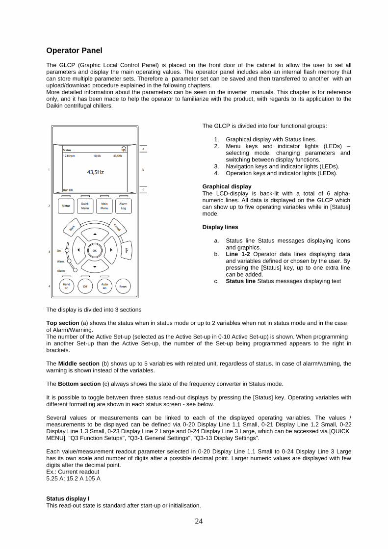
Operator Panel The GLCP (Graphic Local Control Panel) is placed on the front door of the cabinet to allow the user to set all parameters and display the main operating values. The operator panel includes also an internal flash memory that can store multiple parameter sets. Therefore a parameter set can be saved and then transferred to another with an upload/download procedure explained in the following chapters. More detailed information about the parameters can be seen on the inverter manuals. This chapter is for reference only, and it has been made to help the operator to familiarize with the product, with regards to its application to the Daikin centrifugal chillers.
The GLCP is divided into four functional groups:
1. Graphical display with Status lines. 2. Menu keys and indicator lights (LEDs) –
selecting mode, changing parameters and switching between display functions.
3. Navigation keys and indicator lights (LEDs). 4. Operation keys and indicator lights (LEDs).
Graphical display
The LCD-display is back-lit with a total of 6 alpha-numeric lines. All data is displayed on the GLCP which can show up to five operating variables while in [Status] mode. Display lines
a. Status line Status messages displaying icons and graphics.
b. Line 1-2 Operator data lines displaying data
and variables defined or chosen by the user. By pressing the [Status] key, up to one extra line can be added.
c. Status line Status messages displaying text
The display is divided into 3 sections Top section (a) shows the status when in status mode or up to 2 variables when not in status mode and in the case
of Alarm/Warning. The number of the Active Set-up (selected as the Active Set-up in 0-10 Active Set-up) is shown. When programming in another Set-up than the Active Set-up, the number of the Set-up being programmed appears to the right in brackets. The Middle section (b) shows up to 5 variables with related unit, regardless of status. In case of alarm/warning, the
warning is shown instead of the variables. The Bottom section (c) always shows the state of the frequency converter in Status mode.
It is possible to toggle between three status read-out displays by pressing the [Status] key. Operating variables with different formatting are shown in each status screen - see below. Several values or measurements can be linked to each of the displayed operating variables. The values / measurements to be displayed can be defined via 0-20 Display Line 1.1 Small, 0-21 Display Line 1.2 Small, 0-22 Display Line 1.3 Small, 0-23 Display Line 2 Large and 0-24 Display Line 3 Large, which can be accessed via [QUICK MENU], "Q3 Function Setups", "Q3-1 General Settings", "Q3-13 Display Settings". Each value/measurement readout parameter selected in 0-20 Display Line 1.1 Small to 0-24 Display Line 3 Large has its own scale and number of digits after a possible decimal point. Larger numeric values are displayed with few digits after the decimal point. Ex.: Current readout 5.25 A; 15.2 A 105 A Status display I
This read-out state is standard after start-up or initialisation.
25
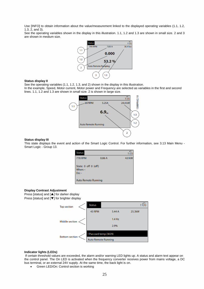
Use [INFO] to obtain information about the value/measurement linked to the displayed operating variables (1.1, 1.2, 1.3, 2, and 3). See the operating variables shown in the display in this illustration. 1.1, 1.2 and 1.3 are shown in small size. 2 and 3 are shown in medium size.
Status display II
See the operating variables (1.1, 1.2, 1.3, and 2) shown in the display in this illustration. In the example, Speed, Motor current, Motor power and Frequency are selected as variables in the first and second lines. 1.1, 1.2 and 1.3 are shown in small size. 2 is shown in large size.
Status display III
This state displays the event and action of the Smart Logic Control. For further information, see 3.13 Main Menu - Smart Logic - Group 13.
Display Contrast Adjustment
Press [status] and [▲] for darker display
Press [status] and [▼] for brighter display
Indicator lights (LEDs)
If certain threshold values are exceeded, the alarm and/or warning LED lights up. A status and alarm text appear on the control panel. The On LED is activated when the frequency converter receives power from mains voltage, a DC bus terminal, or an external 24V supply. At the same time, the back light is on.
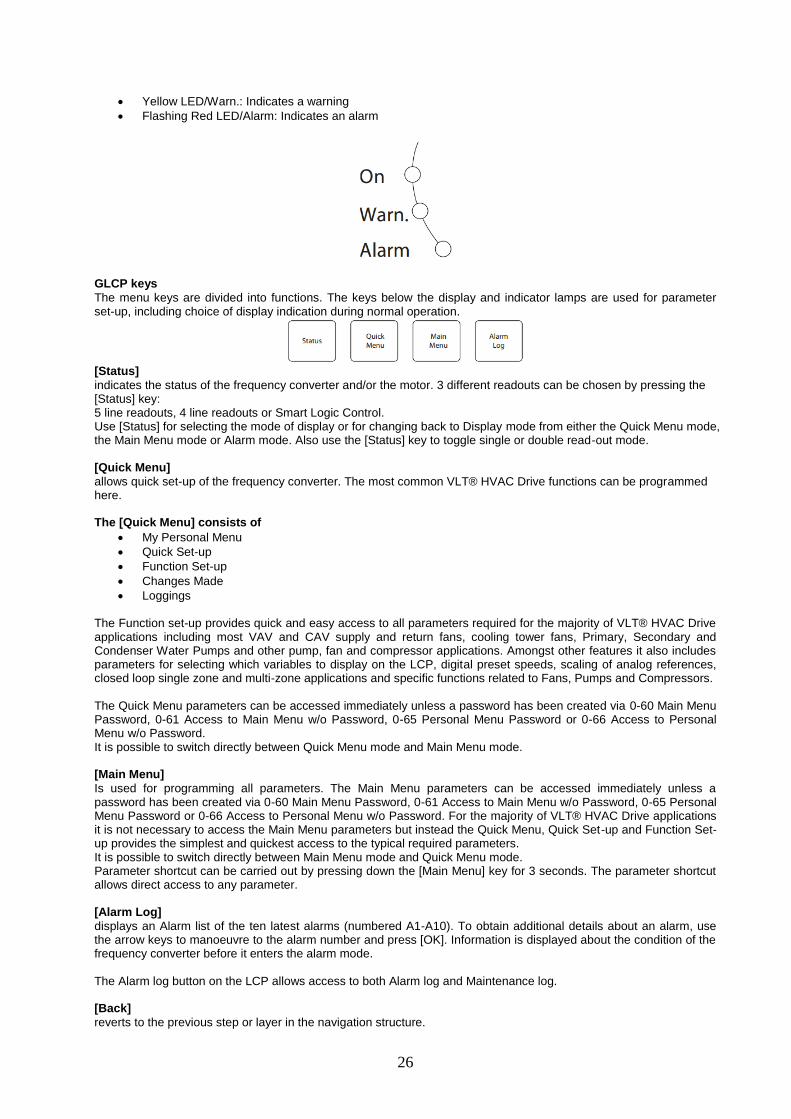
Green LED/On: Control section is working
26
Yellow LED/Warn.: Indicates a warning
Flashing Red LED/Alarm: Indicates an alarm
GLCP keys
The menu keys are divided into functions. The keys below the display and indicator lamps are used for parameter set-up, including choice of display indication during normal operation.
[Status]
indicates the status of the frequency converter and/or the motor. 3 different readouts can be chosen by pressing the [Status] key: 5 line readouts, 4 line readouts or Smart Logic Control. Use [Status] for selecting the mode of display or for changing back to Display mode from either the Quick Menu mode, the Main Menu mode or Alarm mode. Also use the [Status] key to toggle single or double read-out mode. [Quick Menu]
allows quick set-up of the frequency converter. The most common VLT® HVAC Drive functions can be programmed here. The [Quick Menu] consists of
My Personal Menu
Quick Set-up
Function Set-up
Changes Made
Loggings The Function set-up provides quick and easy access to all parameters required for the majority of VLT® HVAC Drive applications including most VAV and CAV supply and return fans, cooling tower fans, Primary, Secondary and Condenser Water Pumps and other pump, fan and compressor applications. Amongst other features it also includes parameters for selecting which variables to display on the LCP, digital preset speeds, scaling of analog references, closed loop single zone and multi-zone applications and specific functions related to Fans, Pumps and Compressors. The Quick Menu parameters can be accessed immediately unless a password has been created via 0-60 Main Menu Password, 0-61 Access to Main Menu w/o Password, 0-65 Personal Menu Password or 0-66 Access to Personal Menu w/o Password. It is possible to switch directly between Quick Menu mode and Main Menu mode. [Main Menu]
Is used for programming all parameters. The Main Menu parameters can be accessed immediately unless a password has been created via 0-60 Main Menu Password, 0-61 Access to Main Menu w/o Password, 0-65 Personal Menu Password or 0-66 Access to Personal Menu w/o Password. For the majority of VLT® HVAC Drive applications it is not necessary to access the Main Menu parameters but instead the Quick Menu, Quick Set-up and Function Set-up provides the simplest and quickest access to the typical required parameters. It is possible to switch directly between Main Menu mode and Quick Menu mode. Parameter shortcut can be carried out by pressing down the [Main Menu] key for 3 seconds. The parameter shortcut allows direct access to any parameter. [Alarm Log]
displays an Alarm list of the ten latest alarms (numbered A1-A10). To obtain additional details about an alarm, use the arrow keys to manoeuvre to the alarm number and press [OK]. Information is displayed about the condition of the frequency converter before it enters the alarm mode. The Alarm log button on the LCP allows access to both Alarm log and Maintenance log. [Back]
reverts to the previous step or layer in the navigation structure.
27
[Cancel]
last change or command will be cancelled as long as the display has not been changed.
[Info]
displays information about a command, parameter, or function in any display window. [Info] provides detailed information when needed. Exit Info mode by pressing either [Info], [Back], or [Cancel].
Navigation Keys
The four navigation arrows are used to navigate between the different choices available in [Quick Menu], [Main Menu] and [Alarm Log]. Use the keys to move the cursor. [OK] is used for choosing a parameter marked by the cursor and for enabling the change of a parameter
Operation Keys for local control are found at the bottom of the control panel
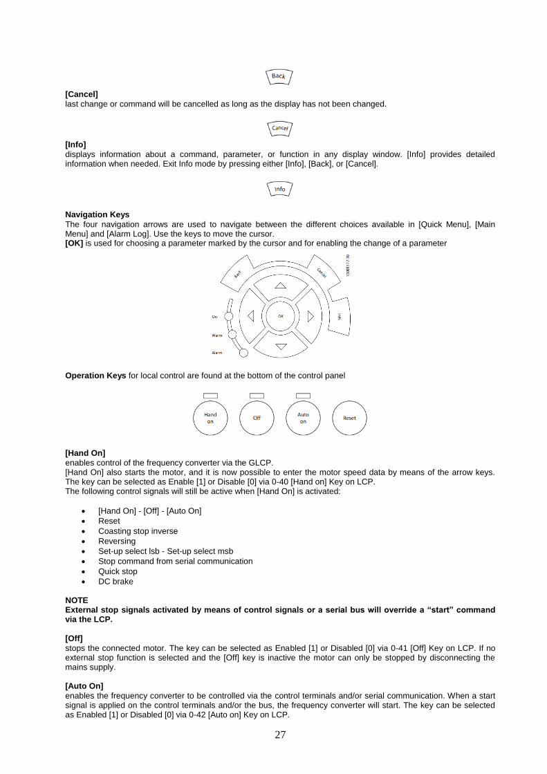
[Hand On]
enables control of the frequency converter via the GLCP. [Hand On] also starts the motor, and it is now possible to enter the motor speed data by means of the arrow keys. The key can be selected as Enable [1] or Disable [0] via 0-40 [Hand on] Key on LCP. The following control signals will still be active when [Hand On] is activated:
[Hand On] - [Off] - [Auto On]
Reset
Coasting stop inverse
Reversing
Set-up select lsb - Set-up select msb
Stop command from serial communication
Quick stop
DC brake NOTE External stop signals activated by means of control signals or a serial bus will override a “start” command via the LCP.
[Off]
stops the connected motor. The key can be selected as Enabled [1] or Disabled [0] via 0-41 [Off] Key on LCP. If no external stop function is selected and the [Off] key is inactive the motor can only be stopped by disconnecting the mains supply. [Auto On]
enables the frequency converter to be controlled via the control terminals and/or serial communication. When a start signal is applied on the control terminals and/or the bus, the frequency converter will start. The key can be selected as Enabled [1] or Disabled [0] via 0-42 [Auto on] Key on LCP.

28
NOTE An active HAND-OFF-AUTO signal via the digital inputs has higher priority than the control keys [Hand On] – Auto On]. [Reset]
is used for resetting the frequency converter after an alarm (trip). It can be selected as [1] Enable or [0] Disable via 0-43 [Reset] Key on LCP. Parameter Set-Up
The frequency converter can be used for practically all assignments, thus offering a significant number of parameters. The series offers a choice between two programming modes - the Quick Menu mode and the Main Menu mode. The latter provides access to all parameters. The former takes the user through a few parameters making it possible to program the majority of VLT ® HVAC Drive applications. Regardless of the mode of programming, parameters can be changed in both Quick Menu mode and in Main Menu mode. Main Menu Mode
Select the Main Menu mode by pressing the [Main Menu] key. The below read-out appears on the display. The middle and bottom sections on the display show a list of parameter groups which can be chosen by toggling the up and down buttons.
Each parameter has a name and number which remain the same regardless of the programming mode. In the Main Menu mode, the parameters are divided into groups. The first digit of the parameter number (from the left) indicates the parameter group number. All parameters can be changed in the Main Menu. However, depending on the choice of configuration (1-00 Configuration Mode), some parameters can be hidden. Parameter Selection
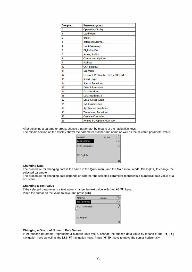
In the Main Menu mode, the parameters are divided into groups. You select a parameter group by means of the navigation keys. The following parameter groups are accessible:
29
After selecting a parameter group, choose a parameter by means of the navigation keys. The middle section on the display shows the parameter number and name as well as the selected parameter value.
Changing Data
The procedure for changing data is the same in the Quick menu and the Main menu mode. Press [OK] to change the selected parameter. The procedure for changing data depends on whether the selected parameter represents a numerical data value or a text value. Changing a Text Value
If the selected parameter is a text value, change the text value with the [▲] [▼] keys.
Place the cursor on the value to save and press [OK].
Changing a Group of Numeric Data Values
If the chosen parameter represents a numeric data value, change the chosen data value by means of the [◀] [▶]
navigation keys as well as the [▲] [▼] navigation keys. Press [◀] [▶] keys to move the cursor horizontally.
30
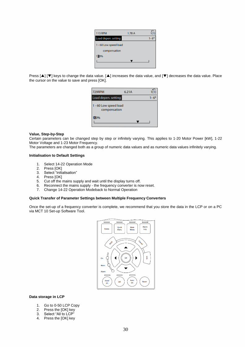
Press [▲] [▼] keys to change the data value. [▲] increases the data value, and [▼] decreases the data value. Place
the cursor on the value to save and press [OK].
Value, Step-by-Step
Certain parameters can be changed step by step or infinitely varying. This applies to 1-20 Motor Power [kW], 1-22 Motor Voltage and 1-23 Motor Frequency. The parameters are changed both as a group of numeric data values and as numeric data values infinitely varying. Initialisation to Default Settings
1. Select 14-22 Operation Mode 2. Press [OK] 3. Select “initialisation” 4. Press [OK] 5. Cut off the mains supply and wait until the display turns off. 6. Reconnect the mains supply - the frequency converter is now reset. 7. Change 14-22 Operation Modeback to Normal Operation
Quick Transfer of Parameter Settings between Multiple Frequency Converters
Once the set-up of a frequency converter is complete, we recommend that you store the data in the LCP or on a PC via MCT 10 Set-up Software Tool.
Data storage in LCP
1. Go to 0-50 LCP Copy 2. Press the [OK] key 3. Select “All to LCP” 4. Press the [OK] key
31
All parameter settings are now stored in the LCP indicated by the progress bar. When 100% is reached, press [OK]. NOTE Stop the motor before performing this operation.
Connect the LCP to another frequency converter and copy the parameter settings to this frequency converter as well. Data transfer from LCP to frequency converter
1. Go to 0-50 LCP Copy 2. Press the [OK] key 3. Select “All from LCP” 4. Press the [OK] key
The parameter settings stored in the LCP are now transferred to the frequency converter indicated by the progress bar. When 100% is reached, press [OK]. NOTE Stop the motor before performing this operation.
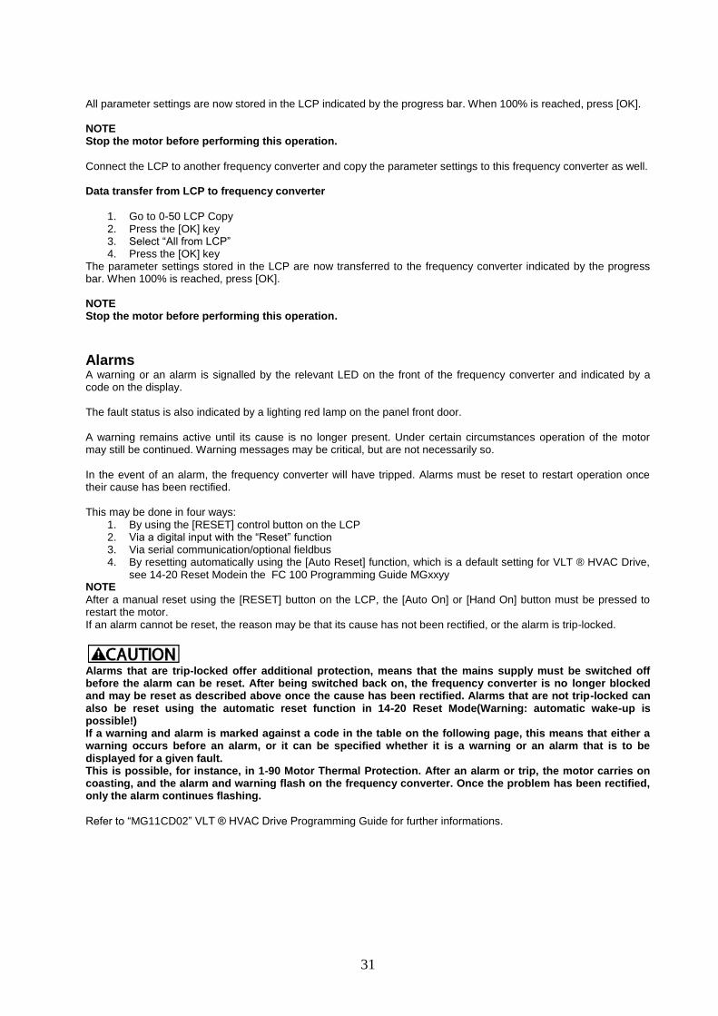
Alarms A warning or an alarm is signalled by the relevant LED on the front of the frequency converter and indicated by a code on the display. The fault status is also indicated by a lighting red lamp on the panel front door. A warning remains active until its cause is no longer present. Under certain circumstances operation of the motor may still be continued. Warning messages may be critical, but are not necessarily so. In the event of an alarm, the frequency converter will have tripped. Alarms must be reset to restart operation once their cause has been rectified. This may be done in four ways:
1. By using the [RESET] control button on the LCP 2. Via a digital input with the “Reset” function 3. Via serial communication/optional fieldbus 4. By resetting automatically using the [Auto Reset] function, which is a default setting for VLT ® HVAC Drive,
see 14-20 Reset Modein the FC 100 Programming Guide MGxxyy NOTE
After a manual reset using the [RESET] button on the LCP, the [Auto On] or [Hand On] button must be pressed to restart the motor. If an alarm cannot be reset, the reason may be that its cause has not been rectified, or the alarm is trip-locked.
Alarms that are trip-locked offer additional protection, means that the mains supply must be switched off before the alarm can be reset. After being switched back on, the frequency converter is no longer blocked and may be reset as described above once the cause has been rectified. Alarms that are not trip-locked can also be reset using the automatic reset function in 14-20 Reset Mode(Warning: automatic wake-up is possible!) If a warning and alarm is marked against a code in the table on the following page, this means that either a warning occurs before an alarm, or it can be specified whether it is a warning or an alarm that is to be displayed for a given fault. This is possible, for instance, in 1-90 Motor Thermal Protection. After an alarm or trip, the motor carries on coasting, and the alarm and warning flash on the frequency converter. Once the problem has been rectified, only the alarm continues flashing.
Refer to “MG11CD02” VLT ® HVAC Drive Programming Guide for further informations.
32
Drive Commissioning
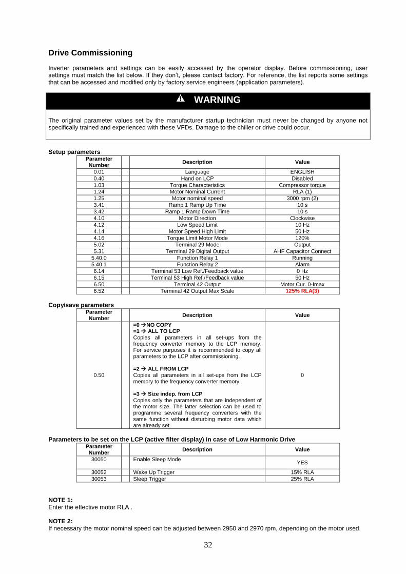
Inverter parameters and settings can be easily accessed by the operator display. Before commissioning, user settings must match the list below. If they don’t, please contact factory. For reference, the list reports some settings that can be accessed and modified only by factory service engineers (application parameters).
WARNING
The original parameter values set by the manufacturer startup technician must never be changed by anyone not specifically trained and experienced with these VFDs. Damage to the chiller or drive could occur.
Setup parameters
Parameter Number
Description Value
0.01 Language ENGLISH
0.40 Hand on LCP Disabled
1.03 Torque Characteristics Compressor torque
1.24 Motor Nominal Current RLA (1)
1.25 Motor nominal speed 3000 rpm (2)
3.41 Ramp 1 Ramp Up Time 10 s
3.42 Ramp 1 Ramp Down Time 10 s
4.10 Motor Direction Clockwise
4.12 Low Speed Limit 10 Hz
4.14 Motor Speed High Limit 50 Hz
4.16 Torque Limit Motor Mode 120%
5.02 Terminal 29 Mode Output
5.31 Terminal 29 Digital Output AHF Capacitor Connect
5.40.0 Function Relay 1 Running
5.40.1 Function Relay 2 Alarm
6.14 Terminal 53 Low Ref./Feedback value 0 Hz
6.15 Terminal 53 High Ref./Feedback value 50 Hz
6.50 Terminal 42 Output Motor Cur. 0-Imax
6.52 Terminal 42 Output Max Scale 125% RLA(3)
Copy/save parameters
Parameter Number
Description Value
0.50
=0 NO COPY =1 ALL TO LCP Copies all parameters in all set-ups from the frequency converter memory to the LCP memory. For service purposes it is recommended to copy all parameters to the LCP after commissioning. =2 ALL FROM LCP Copies all parameters in all set-ups from the LCP memory to the frequency converter memory. =3 Size indep. from LCP Copies only the parameters that are independent of the motor size. The latter selection can be used to programme several frequency converters with the same function without disturbing motor data which are already set
0
Parameters to be set on the LCP (active filter display) in case of Low Harmonic Drive
Parameter Number
Description Value
30050
Enable Sleep Mode
YES
30052 Wake Up Trigger 15% RLA
30053 Sleep Trigger 25% RLA
NOTE 1:
Enter the effective motor RLA . NOTE 2:
If necessary the motor nominal speed can be adjusted between 2950 and 2970 rpm, depending on the motor used.

33
NOTE 3:
Calculate the value starting from the inverter Imax written in the parameter 16.37. The value to be entered in 6.52 parameter is given by the formula:
[(RLA x 1,25)/Imax] x 100 Checks at startup
Item Correct Operation Check
Power On lamp (white) ON with panel powered
Starter Transition lamp (green) ON at compressor running
Fault lamp (red) OFF during normal operation
Ouput Current @ 100% Must match RLA
Electrical panel fan grille ON with panel powered

34
MicroTech IITM
VFD Control General Description:
The following describes the software for centrifugal chillers with variable speed drive and the MicroTech II controller. Complete information on the MicroTech II controller operation is contained in the Operating Manual OM CentrifMicro II. Variable Frequency Drive (VFD) Control:
Digital output NO1, (terminal J12) on the compressor controller is wired to the CR relay (Compressor Relay). The CR relay energizes the MCR (Motor Control Relay) which enables the variable frequency drive instead of a standard motor. Analog output Y1 (terminal J4) on the compressor controller provides the speed setpoint signal to the VFD. The output is a 0-10 VDC analog output signal, hard wired to the VFD. There is no feedback signal required from the variable frequency drive to the MicroTech II controller to indicate the speed of the motor. The actual percent motor speed is within 1% of the analog output signal from the MicroTech II controller. Digital Input ID9 (terminal J7) on the compressor controller is wired to the Vane Open switch (VO switch) that indicates when the vanes are 100% open. If the switch is open, the status of the vanes is Not Open. If the switch is closed, the status of the vanes is Open. Or
If the compressor controller pulses a load output for the vanes to load for a cumulative time of 300 seconds (user adjustable), the MicroTech II controller will assume the compressor is fully loaded the same as if the V.O. switch closed (one unload pulse will reset the timer). Sequence of Operation Compressor Off:
The VFD is turned off, the speed output is 0%, and the vanes are closed. If the chiller is turned on and if there is a load, the chiller will go through its start sequence. The MCR will be energized, the speed signal will be set to minimum speed, and the VFD will start the compressor. When the compressor starts, it will be in the VFD Running, hold speed, adjust vanes mode. VFD Running, Hold Minimum Speed, Adjust Vanes:
The VFD remains on, the command speed is held at Minimum Speed, and the vanes are modulated to maintain the Active LEWT Setpoint. As the load increases; if the vane open switch closes or the MicroTech II controller pulses the vanes open for a cumulative 300 seconds (default), and the LEWT is greater than the active setpoint, the mode switches to “VFD Running Adjust Speed, Open Vanes”. Otherwise, the controller stays in this mode with the speed at Minimum Speed and the vanes being controlled to satisfy the Active LEWT Setpoint. VFD Running, Adjust Speed, Open Vanes:
The VFD remains on, the speed output is modulated to maintain the Active LEWT Setpoint, and the vanes are driven to the open position. As the load decreases, if the speed equals the lift temperature control speed and the LEWT is less than the active LEWT setpoint, the mode switches to “VFD Running, Hold Minimum Speed, Adjust Vanes”. Otherwise, the controller stays in this mode. Compressor Shutdown:
The VFD remains on, the speed output remains constant, and the vanes are driven closed (shutdown unload state). This state is used during a routine shutdown of the chiller. If there is a rapid shutdown caused by a fault alarm, the MCR will be immediately deenergized, the speed signal will go to zero, and the compressor state will go directly to Postlube. Dual Compressor VFD Operation
The MicroTech II controller has the capability to control a dual compressor VFD chiller or multiple stand alone VFD chillers with interconnecting network communications, including all compressor staging and load balance functions. (See OMCentrifMicro II for set up of multiple compressor staging). General Dual Compressor VFD Operation
The first compressor starts and runs as a single VFD compressor controlling speed and vane position based on LEWT (Leaving Evaporator Water Temperature). When the capacity of the first compressor reaches “Full Load” and LEWT is greater than stage delta, and the slope (pull down rate) is less than the user adjustable minimum rate setpoint, the next compressor will be enabled. Dual Compressor Unit Stage Down
When “Compressor Capacity” exceeds calculated system load (internal algorithm), the “next off” compressor will be disabled. When the “next off” compressor is disabled, the controller will unload the compressor by closing the vanes (shutdown unload) to unload the compressor. The load balance function will make the other compressor follow. When the
35
shutdown unload timer expires, or the vane close switch closes (which ever occurs first), the MCR will de-energized, and the controller will transition to the post lube sequence. At the end of the post lube timer, the oil pump will be turned off and the controller will transition to the off sequence. Interface Panel Screens, MT II NOTE: This section contains the MicroTech II controller and Operator Interface Panel display screens.
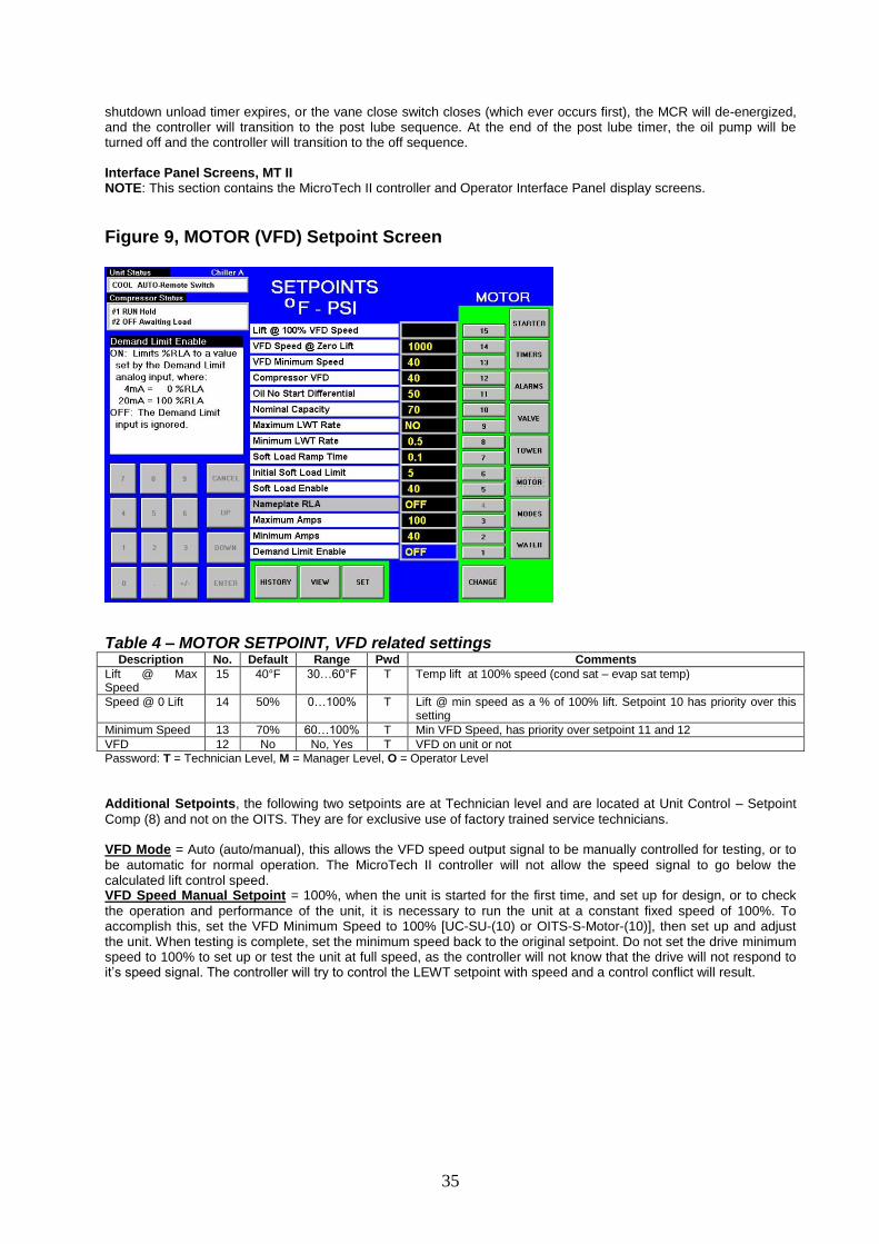
Figure 9, MOTOR (VFD) Setpoint Screen
Table 4 – MOTOR SETPOINT, VFD related settings Description No. Default Range Pwd Comments
Lift @ Max Speed
15 40°F 30…60°F T Temp lift at 100% speed (cond sat – evap sat temp)
Speed @ 0 Lift 14 50% 0…100% T Lift @ min speed as a % of 100% lift. Setpoint 10 has priority over this setting
Minimum Speed 13 70% 60…100% T Min VFD Speed, has priority over setpoint 11 and 12
VFD 12 No No, Yes T VFD on unit or not
Password: T = Technician Level, M = Manager Level, O = Operator Level
Additional Setpoints, the following two setpoints are at Technician level and are located at Unit Control – Setpoint
Comp (8) and not on the OITS. They are for exclusive use of factory trained service technicians. VFD Mode = Auto (auto/manual), this allows the VFD speed output signal to be manually controlled for testing, or to
be automatic for normal operation. The MicroTech II controller will not allow the speed signal to go below the calculated lift control speed. VFD Speed Manual Setpoint = 100%, when the unit is started for the first time, and set up for design, or to check
the operation and performance of the unit, it is necessary to run the unit at a constant fixed speed of 100%. To accomplish this, set the VFD Minimum Speed to 100% [UC-SU-(10) or OITS-S-Motor-(10)], then set up and adjust the unit. When testing is complete, set the minimum speed back to the original setpoint. Do not set the drive minimum speed to 100% to set up or test the unit at full speed, as the controller will not know that the drive will not respond to it’s speed signal. The controller will try to control the LEWT setpoint with speed and a control conflict will result.
36
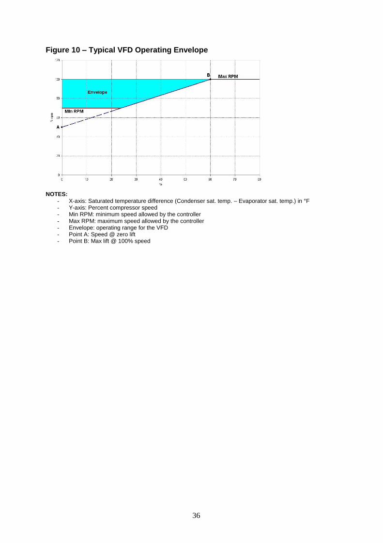
Figure 10 – Typical VFD Operating Envelope
NOTES:
- X-axis: Saturated temperature difference (Condenser sat. temp. – Evaporator sat. temp.) in °F - Y-axis: Percent compressor speed - Min RPM: minimum speed allowed by the controller - Max RPM: maximum speed allowed by the controller - Envelope: operating range for the VFD - Point A: Speed @ zero lift - Point B: Max lift @ 100% speed
37
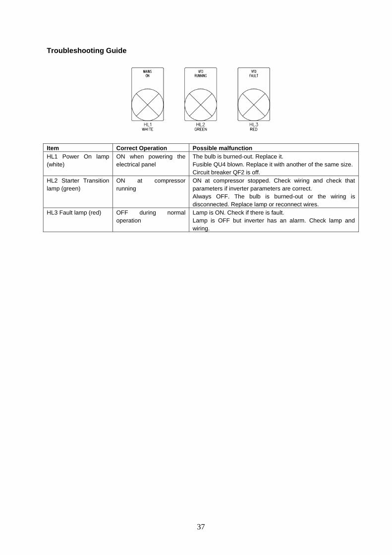
Troubleshooting Guide
Item Correct Operation Possible malfunction
HL1 Power On lamp
(white)
ON when powering the
electrical panel
The bulb is burned-out. Replace it.
Fusible QU4 blown. Replace it with another of the same size.
Circuit breaker QF2 is off.
HL2 Starter Transition
lamp (green)
ON at compressor
running
ON at compressor stopped. Check wiring and check that
parameters if inverter parameters are correct.
Always OFF. The bulb is burned-out or the wiring is
disconnected. Replace lamp or reconnect wires.
HL3 Fault lamp (red) OFF during normal
operation
Lamp is ON. Check if there is fault.
Lamp is OFF but inverter has an alarm. Check lamp and
wiring.

38
Maintenance
Safety Instructions Only qualified and authorized personnel have access to the electrical cabinet. Service, maintenance and inspection
personnel must be properly qualified. If they do not have the required experience, they must be trained and instructed. The owner must be sure that the contents of the manual have been totally understood by the personnel.
The non observance of the safety instructions may cause serious injury or damage the environment and the unit,
invalidating any right to compensation for damage. It may for example cause the following dangers:
Failure of important functions of the unit/installation;
Injury to people due to electrical or mechanical causes
Danger to the environment due to electrical or mechanical causes.
The safety instructions, the national regulations for accident prevention of this manual, as well as internal regulations
for working, operating and safety –if existing– must be observed.
Do not remove any cover from the electrical cabinet.
Do not open live electrical cabinets.
Before any work on the electrical cabinet is started, the electrical cabinet must be disconnected using the door-
handle switch; it is essential to follow the procedures of this manual for the disconnection of the cabinet.
When the work is finished, all safety and protection devices must be connected or started again.
Modifications or changes to the electrical cabinet are allowed only after consultations with the manufacturer. Original
spare parts and accessories authorised by the manufacturer are essential for compliance with safety requirements.
The use of other parts can invalidate any claim for responsibility for the consequences.
The customer should ensure that all control, inspection and installation works are carried out by authorized and
qualified personnel, well informed about work instructions. Well planned inspections help avoiding expensive and
useless repairs.
Periodic Inspection
WARNING
Always turn off the power supply before beginning the inspection. Confirm that LED indicators on the front cover have all turned off, then wait the time mentioned on the yellow label has elapsed before beginning the inspection. Be sure not to touch terminals right after the power has been turned off. Doing so can result in electric shock.
Check the following items during periodic maintenance.
Period Item Inspection Corrective Action
Monthly External terminals,
mounting bolts,
connectors
Are all connectors, screws and bolts tight? Reconnect the loose connectors.
Tighten loose screws and bolts
firmly
Cooling fans filter fins Are the air filters dirty or dusty? Cleanup any dirt and dust with an
airgun using max 6 bar
PCB’s Is there any conductive dirt or oil mist on
the PCB’s?
Cleanup any dirt and dust with an
airgun using max 6 bar
Cooling Fans Is there any abnormal noise or vibration or
has the total operating time exceeded
20,000 hours?
Replace the cooling fans
DC Capacitors Are there any irregularities, such as
discolouration or odour?
Replace the DC capacitors of the
Period Item Inspection Corrective Action
Yearly Busbar Is there any dust? Clean
Bolts Are they tightened? Tighten
Main Switch, contactors Pour some lubricating oil on the mechanism
Door Handle Lubricate
39
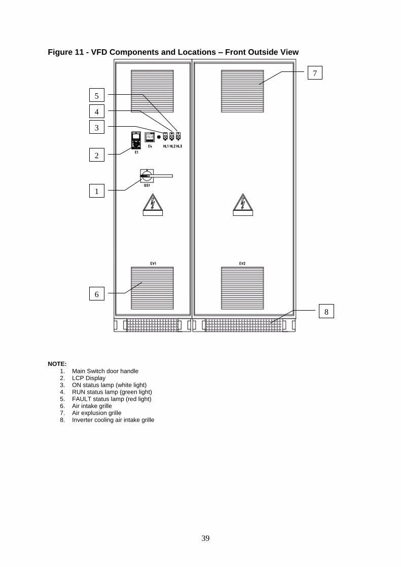
Figure 11 - VFD Components and Locations – Front Outside View
NOTE:
1. Main Switch door handle 2. LCP Display 3. ON status lamp (white light) 4. RUN status lamp (green light) 5. FAULT status lamp (red light) 6. Air intake grille 7. Air explusion grille 8. Inverter cooling air intake grille
1
2
3
4
5
6
7
8
40
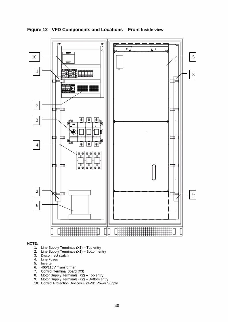
Figure 12 - VFD Components and Locations – Front Inside view
NOTE:
1. Line Supply Terminals (X1) – Top entry 2. Line Supply Terminals (X1) – Bottom entry 3. Disconnect switch 4. Line Fuses 5. Inverter 6. 400/115V Transformer 7. Control Terminal Board (X3) 8. Motor Supply Terminals (X2) – Top entry 9. Motor Supply Terminals (X2) – Bottom entry 10. Control Protection Devices + 24Vdc Power Supply
3
1
2
4
5
6
7
8
9
10
41
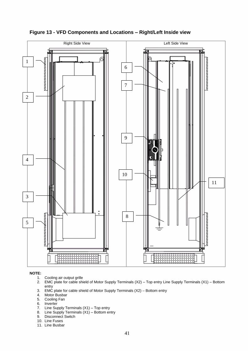
Figure 13 - VFD Components and Locations – Right/Left Inside view
Right Side View
Left Side View
NOTE:
1. Cooling air output grille 2. EMC plate for cable shield of Motor Supply Terminals (X2) – Top entry Line Supply Terminals (X1) – Bottom
entry 3. EMC plate for cable shield of Motor Supply Terminals (X2) – Bottom entry 4. Motor Busbar 5. Cooling Fan 6. Inverter 7. Line Supply Terminals (X1) – Top entry 8. Line Supply Terminals (X1) – Bottom entry 9. Disconnect Switch 10. Line Fuses 11. Line Busbar
1
2
3
5
4
11
9
10
6
7
8
42
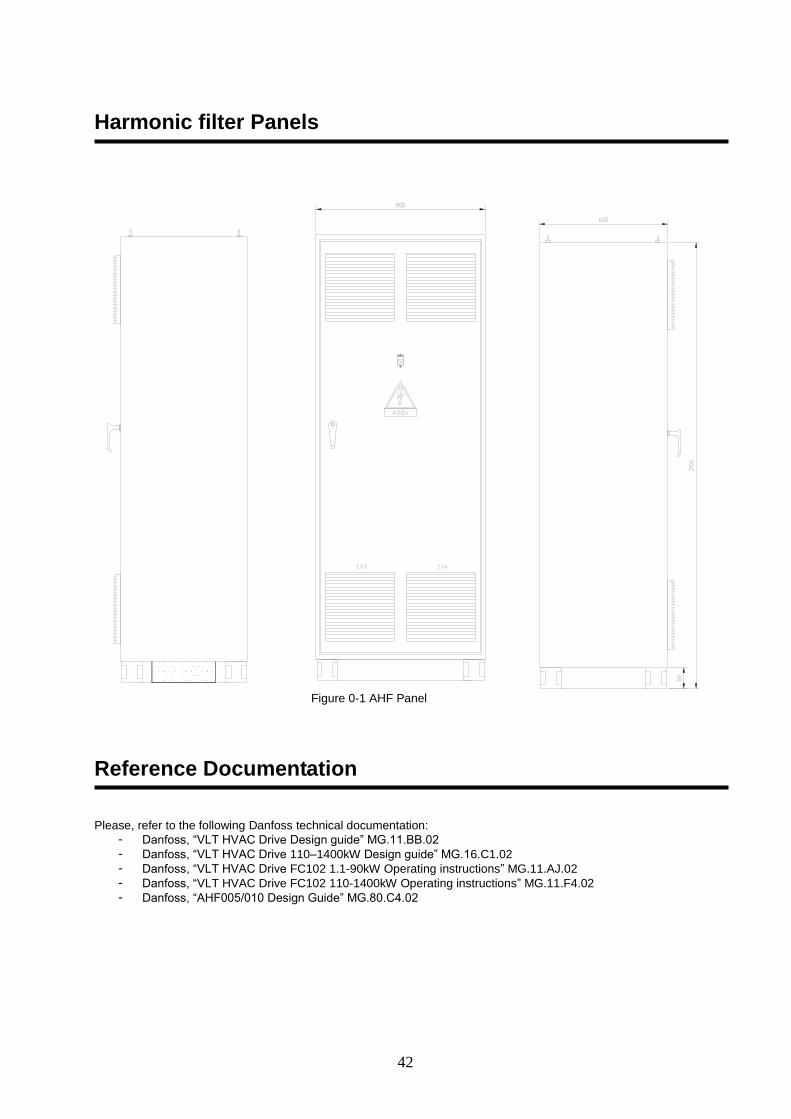
Harmonic filter Panels
Figure 0-1 AHF Panel
Reference Documentation Please, refer to the following Danfoss technical documentation:
- Danfoss, “VLT HVAC Drive Design guide” MG.11.BB.02
- Danfoss, “VLT HVAC Drive 110–1400kW Design guide” MG.16.C1.02
- Danfoss, “VLT HVAC Drive FC102 1.1-90kW Operating instructions” MG.11.AJ.02
- Danfoss, “VLT HVAC Drive FC102 110-1400kW Operating instructions” MG.11.F4.02
- Danfoss, “AHF005/010 Design Guide” MG.80.C4.02
43
Technical Characteristics To know the technical characteristics of harmonic filters, please refer to the instruction manual Danfoss cod. MG.80.C4.02 “AHF005/010 DESIGN GUIDE” by selecting the desired model. The electrical panel containing the harmonic filter has the following dimensions in mm, regardless of its size: 800 (L) x 2100 (A) x 600 (P) The weight of the panel varies depending on harmonic filter size.
Terms of Supply The harmonic filter comes complete with the following parts:
- Set of input cables connected only to the harmonic filter input terminals (L1 / L2 / L3), including the ground wire, the other end is free;
- Set the output cables connected only to the harmonic filter output terminals (L12 / L22 / L32), including the ground wire, the other end is free;
- Multicore cable 12G2, 5 connected to the terminal board M3, the other end is free;
- Cable raceway width 300mm, height 100mm. The length will be adequate to cross the entire width of the cabinets QG and QG1.
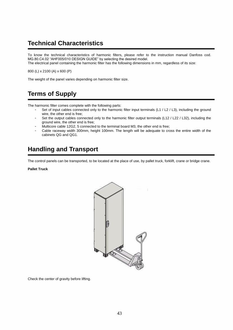
Handling and Transport The control panels can be transported, to be located at the place of use, by pallet truck, forklift, crane or bridge crane. Pallet Truck
Check the center of gravity before lifting.
44
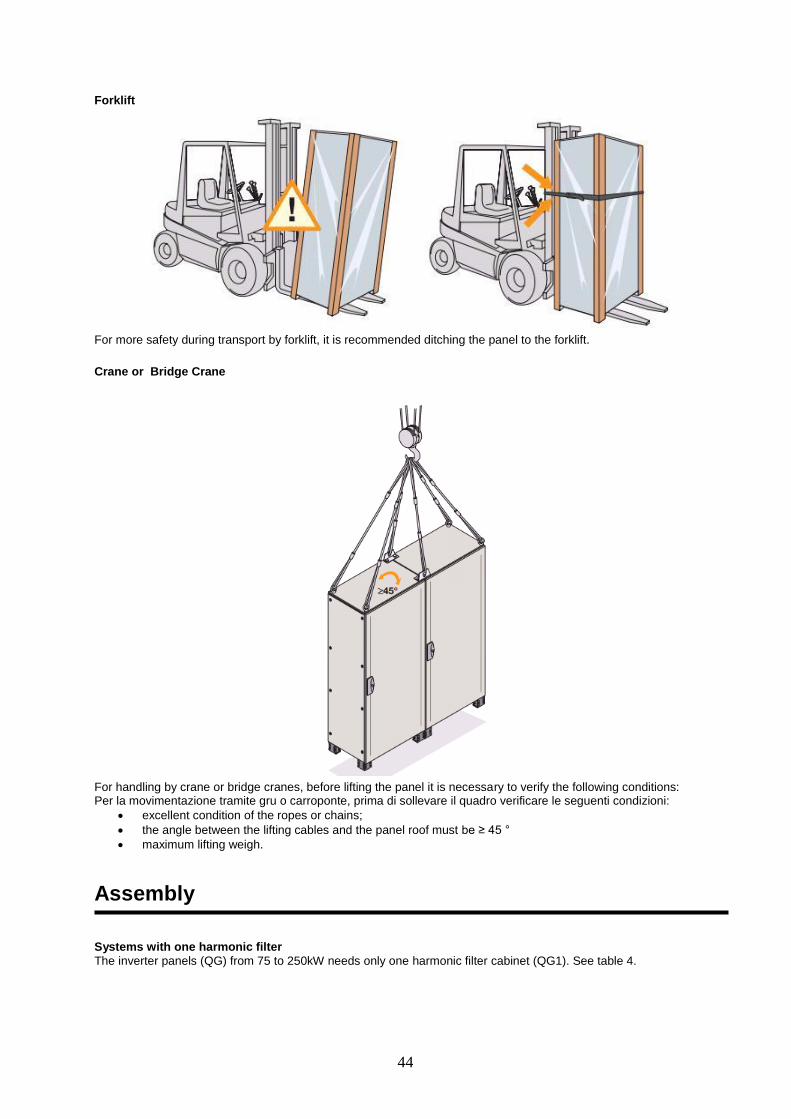
Forklift
For more safety during transport by forklift, it is recommended ditching the panel to the forklift.
Crane or Bridge Crane
For handling by crane or bridge cranes, before lifting the panel it is necessary to verify the following conditions: Per la movimentazione tramite gru o carroponte, prima di sollevare il quadro verificare le seguenti condizioni:
excellent condition of the ropes or chains;
the angle between the lifting cables and the panel roof must be ≥ 45 °
maximum lifting weigh.
Assembly Systems with one harmonic filter
The inverter panels (QG) from 75 to 250kW needs only one harmonic filter cabinet (QG1). See table 4.
45
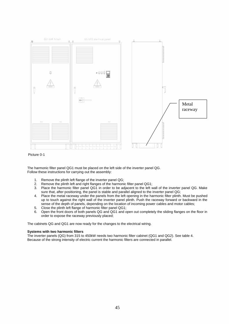
Picture 0-1
The harmonic filter panel QG1 must be placed on the left side of the inverter panel QG. Follow these instructions for carrying out the assembly:
1. Remove the plinth left flange of the inverter panel QG; 2. Remove the plinth left and right flanges of the harmonic filter panel QG1; 3. Place the harmonic filter panel QG1 in order to be adjacent to the left wall of the inverter panel QG. Make
sure that, after positioning, the panel is stable and parallel aligned to the inverter panel QG; 4. Place the metal raceway under the panels from the left opening in the harmonic filter plinth. Must be pushed
up to touch against the right wall of the inverter panel plinth. Push the raceway forward or backward in the sense of the depth of panels, depending on the location of incoming power cables and motor cables;
5. Close the plinth left flange of harmonic filter panel QG1; 6. Open the front doors of both panels QG and QG1 and open out completely the sliding flanges on the floor in
order to expose the raceway previously placed; The cabinets QG and QG1 are now ready for the changes to the electrical wiring. Systems with two harmonic filters
The inverter panels (QG) from 315 to 450kW needs two harmonic filter cabinet (QG1 and QG2). See table 4. Because of the strong intensity of electric current the harmonic filters are connected in parallel.
Metal
raceway
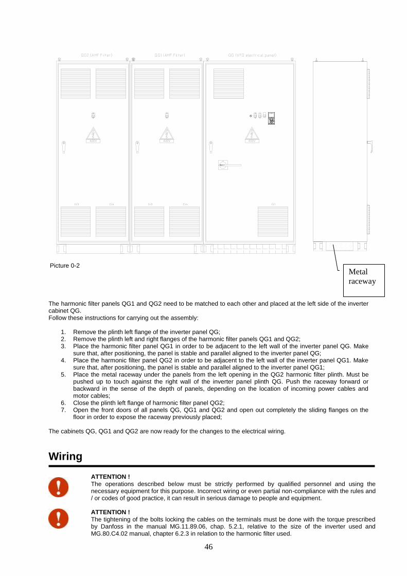
46
Picture 0-2
The harmonic filter panels QG1 and QG2 need to be matched to each other and placed at the left side of the inverter cabinet QG. Follow these instructions for carrying out the assembly:
1. Remove the plinth left flange of the inverter panel QG; 2. Remove the plinth left and right flanges of the harmonic filter panels QG1 and QG2; 3. Place the harmonic filter panel QG1 in order to be adjacent to the left wall of the inverter panel QG. Make
sure that, after positioning, the panel is stable and parallel aligned to the inverter panel QG; 4. Place the harmonic filter panel QG2 in order to be adjacent to the left wall of the inverter panel QG1. Make
sure that, after positioning, the panel is stable and parallel aligned to the inverter panel QG1; 5. Place the metal raceway under the panels from the left opening in the QG2 harmonic filter plinth. Must be
pushed up to touch against the right wall of the inverter panel plinth QG. Push the raceway forward or backward in the sense of the depth of panels, depending on the location of incoming power cables and motor cables;
6. Close the plinth left flange of harmonic filter panel QG2; 7. Open the front doors of all panels QG, QG1 and QG2 and open out completely the sliding flanges on the
floor in order to expose the raceway previously placed; The cabinets QG, QG1 and QG2 are now ready for the changes to the electrical wiring.
Wiring
ATTENTION !
The operations described below must be strictly performed by qualified personnel and using the necessary equipment for this purpose. Incorrect wiring or even partial non-compliance with the rules and / or codes of good practice, it can result in serious damage to people and equipment.
ATTENTION !
The tightening of the bolts locking the cables on the terminals must be done with the torque prescribed by Danfoss in the manual MG.11.89.06, chap. 5.2.1, relative to the size of the inverter used and MG.80.C4.02 manual, chapter 6.2.3 in relation to the harmonic filter used.
Metal
raceway
47
Systems with one harmonic filter
1. In the inverter panel QG disconnect the cables L1, L2 and L3 from the disconnector QU1 and from the inverter FC102 input terminals. These cables will be no longer used.
2. In the harmonic filter panel QG1, take the free end of the power cables L1, L2, L3 and PE (input harmonic filter ) and pass them into the metal conduit beneath the base and then blast them out in the inverter panel QG. Connect the cables L1, L2 and L3 to the output terminals of the disconnector QU1 using the appropriate bolts removed previously, respecting the numbering shown on the wiring diagram. Connect the PE cable on the PE busbar inside QG panel.
3. In the harmonic filter panel QG1 take the free end of the power cables L12, L22, L32 and PE (output of the harmonic filter ) and pass them into the metal conduit beneath the base, then blast them out in the inverter panel QG. Connect to the input terminals of the inverter FC102 using the appropriate bolts removed previously, respecting the numbering shown on the wiring diagram. Connect the PE cable on the PE busbar inside QG panel.
4. In the harmonic filter panel QG1 take the free end of the cable 12G2, 5 (terminal board M1) and slide it inside the metal conduit beneath the base and blast them out in the inverter panel QG. Connect the wires to the terminal board M2 respecting the numbering shown on the wiring diagram.
5. Slide the cables pass-thru flanges on the bottom of the two cabinets in order to close the opening as much as possible.
Systems with two harmonic filter
1. In the inverter panel QG disconnect the cables L1, L2 and L3 from the disconnector QU1 and from the inverter FC102 input terminals. These cables will be no longer used.
2. In the harmonic filter panel QG1, take the free end of the power cables L1, L2, L3 and PE (input harmonic filter ) and pass them into the metal conduit beneath the base and then blast them out in the inverter panel QG. Connect the cables L1, L2 and L3 to the output terminals of the disconnector QU1 using the appropriate bolts removed previously, respecting the numbering shown on the wiring diagram. Connect the PE cable on the PE busbar inside QG panel.
3. In the harmonic filter panel QG1, take the free end of the power cables L12, L22, L32 and PE (harmonic filter output) and pass them into the metal conduit beneath the base and then blast them out in the inverter panel QG. Connect the cables L12, L22 and L32 to the FC102 inverter input terminals using the appropriate bolts removed previously, respecting the numbering shown on the wiring diagram. Connect the PE cable on the PE busbar inside QG panel. Please note that the harmonic filter panels QG1 and QG2 have half of the conductors provided for by the panel QG for each phase, this to allow the parallel connection of the two harmonic filters to the panel QG.
4. In the harmonic filter panel QG1 take the free end of the cable 12G2, 5 (terminal board M1) and slide it inside the metal conduit beneath the base and blast them out in the inverter panel QG. Connect the wires to the terminal board M2 respecting the numbering shown on the wiring diagram.
Repeat the operations described in steps 2 to 4 for the harmonic filter panel QG2.
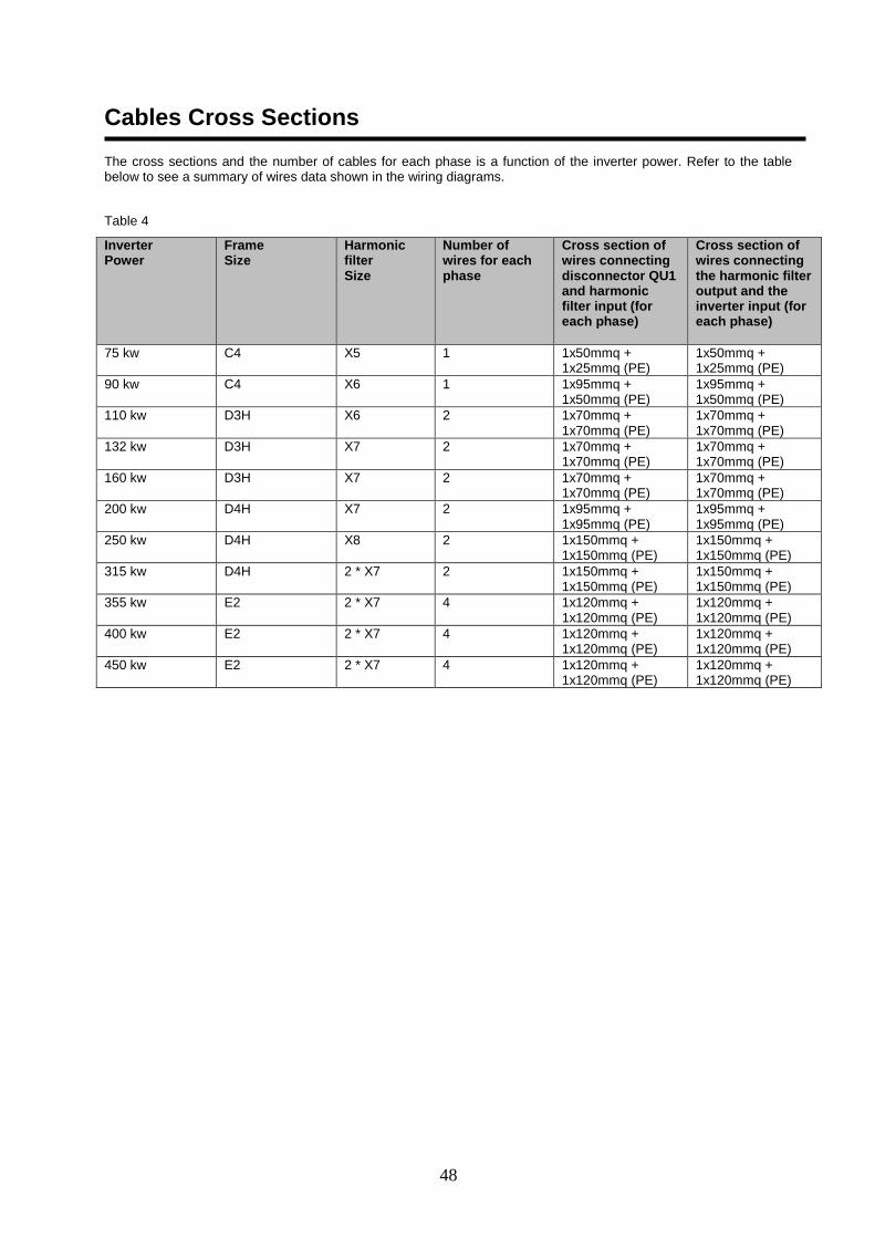
48
Cables Cross Sections The cross sections and the number of cables for each phase is a function of the inverter power. Refer to the table below to see a summary of wires data shown in the wiring diagrams.
Table 4
Inverter Power
Frame Size
Harmonic filter Size
Number of wires for each phase
Cross section of wires connecting disconnector QU1 and harmonic filter input (for each phase)
Cross section of wires connecting the harmonic filter output and the inverter input (for each phase)
75 kw C4 X5 1 1x50mmq + 1x25mmq (PE)
1x50mmq + 1x25mmq (PE)
90 kw C4 X6 1 1x95mmq + 1x50mmq (PE)
1x95mmq + 1x50mmq (PE)
110 kw D3H X6 2 1x70mmq + 1x70mmq (PE)
1x70mmq + 1x70mmq (PE)
132 kw D3H X7 2 1x70mmq + 1x70mmq (PE)
1x70mmq + 1x70mmq (PE)
160 kw D3H X7 2 1x70mmq + 1x70mmq (PE)
1x70mmq + 1x70mmq (PE)
200 kw D4H X7 2 1x95mmq + 1x95mmq (PE)
1x95mmq + 1x95mmq (PE)
250 kw D4H X8 2 1x150mmq + 1x150mmq (PE)
1x150mmq + 1x150mmq (PE)
315 kw D4H 2 * X7 2 1x150mmq + 1x150mmq (PE)
1x150mmq + 1x150mmq (PE)
355 kw E2 2 * X7 4 1x120mmq + 1x120mmq (PE)
1x120mmq + 1x120mmq (PE)
400 kw E2 2 * X7 4 1x120mmq + 1x120mmq (PE)
1x120mmq + 1x120mmq (PE)
450 kw E2 2 * X7 4 1x120mmq + 1x120mmq (PE)
1x120mmq + 1x120mmq (PE)
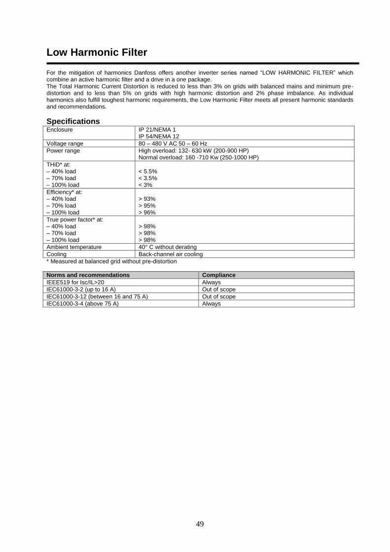
49
Low Harmonic Filter For the mitigation of harmonics Danfoss offers another inverter series named “LOW HARMONIC FILTER” which combine an active harmonic filter and a drive in a one package. The Total Harmonic Current Distortion is reduced to less than 3% on grids with balanced mains and minimum pre-distortion and to less than 5% on grids with high harmonic distortion and 2% phase imbalance. As individual harmonics also fulfill toughest harmonic requirements, the Low Harmonic Filter meets all present harmonic standards and recommendations.
Specifications Enclosure IP 21/NEMA 1
IP 54/NEMA 12
Voltage range 80 – 480 V AC 50 – 60 Hz
Power range High overload: 132- 630 kW (200-900 HP) Normal overload: 160 -710 Kw (250-1000 HP)
THiD* at: – 40% load – 70% load – 100% load
< 5.5% < 3.5% < 3%
Efficiency* at: – 40% load – 70% load – 100% load
> 93% > 95% > 96%
True power factor* at: – 40% load – 70% load – 100% load
> 98% > 98% > 98%
Ambient temperature 40° C without derating
Cooling Back-channel air cooling
* Measured at balanced grid without pre-distortion
Norms and recommendations Compliance
IEEE519 for Isc/IL>20 Always
IEC61000-3-2 (up to 16 A) Out of scope
IEC61000-3-12 (between 16 and 75 A) Out of scope
IEC61000-3-4 (above 75 A) Always

50
The present publication is drawn up by of information only and does not constitute an offer binding upon Daiki Applied Europe S.p.A.. Daikin Applied Europe S.p.A. has compiled the content of this publication to the best of its knowledge. No express or implied warranty is given for the completeness, accuracy, reliability or fitness for particular purpose of its content, and the products and services presented therein. Specification are subject to change without prior notice. Refer to the data communicated at the time of the order. Daikin Applied
Europe S.p.A. explicitly rejects any liability for any direct or indirect damage, in the broadest sense, arising from or related to the use and/or interpretation of this publication. All content is copyrighted by Daikiny Applied Europe S.p.A..
DAIKIN APPLIED EUROPE S.p.A. Via Piani di Santa Maria, 72 - 00040 Ariccia (Roma) - Italia Tel: (+39) 06 93 73 11 - Fax: (+39) 06 93 74 014 http://www.daikinapplied.eu