Embed Size (px)
Citation preview
Turbo-Lux® 3Orifice Plate Flowmeter
FM, LPCB and VdS approved
OPERATING INSTRUCTIONS
© MECON GmbH BA / Turbo-Lux® 3 / EN / 19-04

2 © MECON GmbH BA / Turbo-Lux® 3 / EN / 19-04
IMPRINT
All rights reserved. Any reproduction or usage without written authorisation of MECON GmbH - even partial content - is strictly prohibited.
Subject to change without notice.
Copyright 2019 by MECON GmbH - Röntgenstr. 105 - 50169 Kerpen - Germany
3© MECON GmbH BA / Turbo-Lux® 3 / EN / 19-04
Inhalt
1 SAFETYINSTRUCTIONS ............................................................................................41.1 Intended use ......................................................................................................................41.2 Certifications......................................................................................................................41.3 Safety instructions from the manufacturer ..............................................................5
2 DEVICEDESCRIPTION ................................................................................................62.1 Scope of delivery ..............................................................................................................62.2 Nameplate ...........................................................................................................................7
3 INSTALLATIONANDMODEOFOPERATION ............................................................83.1 Installation notes ..............................................................................................................83.2 Installation instructions ..................................................................................................83.3 Mode of operation .............................................................................................................10
4 START-UP .....................................................................................................................11
5 TECHNICALDATA ........................................................................................................135.1 Dimensions and weights .................................................................................................14
6 DESCRIPTIONCODE ....................................................................................................16
7 SERVICE ........................................................................................................................187.1 Storage ................................................................................................................................187.2 Maintenance .......................................................................................................................187.3 Returning the device to the manufacturer ................................................................187.4 Disposal ...............................................................................................................................19
4 © MECON GmbH BA / Turbo-Lux® 3 / EN / 19-04
SAFETY INSTRUCTIONS
1 SAFETYINSTRUCTIONS
1.1 Intended use
TheorificeplateflowmeterTurbo-Lux® 3 is used to measure the volume of water in closed conduits.Itissuitableforanypointofinstallation,mountingpositionandflowdirection(in compliance of the directional arrow).
The necessary approvals of the FM Approvals, LPCB and VdS Schadenverhütung GmbH are available.
Warning!
The operator of these measuring devices is solely responsible for the sui-tability, intended use and corrosion resistance of the selected materials. It must be particularly ensured that the materials selected for the wetted parts of the flowmeter are suitable for the process media to be measured.
The manufacturer is not liable for any damage resulting from improper or unintended use of these devices.
The device may only be used in the operating instruction specified pressu-re and temperature limits.
1.2 Certifications
» FM Approval Class: 1046 » LPCB Approval LPS 1045 » VdS Approval 2344, 2100-29
5© MECON GmbH BA / Turbo-Lux® 3 / EN / 19-04
SAFETY INSTRUCTIONS
1.3 Safetyinstructionsfromthemanufacturer
The manufacturer is not liable for damages of any kind caused by the use of the device, including, but not limited to direct, indirect, incidental, punitive and consequential dama-ges.
For every product purchased from the manufacturer warranty applies, according to the relevant product documentation and the valid terms and conditions.
The manufacturer reserves the right to revise the content of the documents, including this disclaimer, without notice, and is not liable in any way for possible consequences of such changes.
The responsibility that the instruments are suitable for the particular application rests solely with the operator. The MECON GmbH assumes no liability for the consequences ofmisuse,modificationsorrepairsthatwerecarriedoutbythecustomerwithoutpriorconsultation.
In case of a complaint the contested elements must be cleaned of hazardous substances and to be returned to the manufacturer unless otherwise agree (see 7.3).
To prevent injury to the user or damage to the unit, it is necessary that you reading this operating instruction carefully before starting using the device.
The instruction is intended for both the correct installation, operation and maintenance of the equipment.
Special designs for special applications and custom models are not covered by this do-cumentation.

6 © MECON GmbH BA / Turbo-Lux® 3 / EN / 19-04
DEVICE DESCRIPTION
2 DEVICEDESCRIPTION
2.1 Scopeofdelivery
OrificeplateflowmeterTurbo-Lux® 3Operating instructionsCertificate(partiallyoptional)Replacement gaskets (not shown here)
Fig. 1 Scope of delivery
7© MECON GmbH BA / Turbo-Lux® 3 / EN / 19-04
DEVICE DESCRIPTION
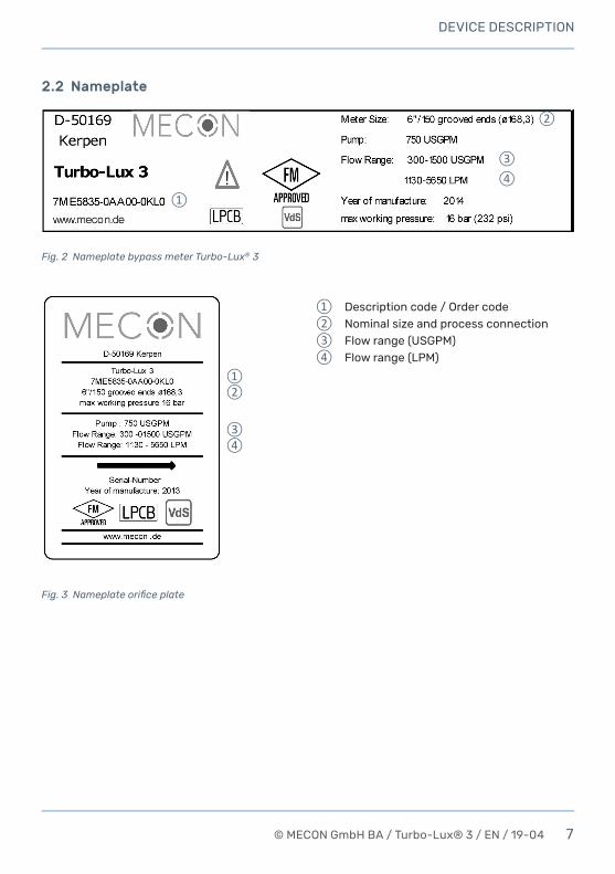
2.2 Nameplate
Description code / Order codeNominal size and process connectionFlow range (USGPM)Flow range (LPM)
Fig. 2 Nameplate bypass meter Turbo-Lux® 3
Fig. 3 Nameplate orifice plate

8 © MECON GmbH BA / Turbo-Lux® 3 / EN / 19-04
INSTALLATION AND MODE OF OPERATION
3 INSTALLATIONANDMODEOFOPERATION
3.1 Installationnotes
Information!
All instruments are carefully checked for proper function before shipment. Check immediately on receipt, the outer packing carefully for damage or signs of improper handling.
Report damage to the carrier and your locale sale staff. In such cases, a description of the defect, the type and the serial number of the device is indicated.
Unpack the unit carefully to avoid damage.
Check the completeness of the delivery against the packing list. Check the name plate, if the delivered flow meter according to your order.
Special requirements VdS: The version with rolled grooved ends may only be used in combination with VdS-approved pipe couplings manufactu-red by Anvil (Gruvlok mechanical grooved couplings), Jinan Meide (cas-ting couplings type 1G), Minimax, Modgal, Tyco (Grinnell Mechanical und G-Fire steel IPS couplings) and Victaulic (except pipe couplings of the type "Style 77").
3.2 Installationinstructions
Installationoftheorificeplate
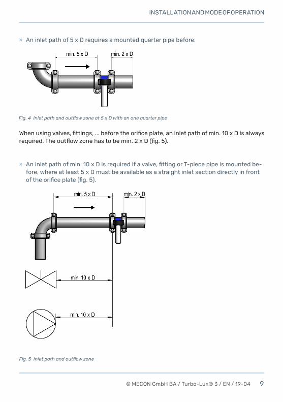
Beforeandaftertheorificeplateastraightcalmingsectionisprovidedasafunctionofthe nominal diameter (D).
With an installation of an one quarter pipe (independend of the direction) the distance of theinletpathofmin.5xDandanoutflowzoneof2xDisrequired.Theconnectedpipeshavetobeofthesamesizeastheorificeplate.
9© MECON GmbH BA / Turbo-Lux® 3 / EN / 19-04
INSTALLATION AND MODE OF OPERATION
Fig. 4 Inlet path and outflow zone at 5 x D with an one quarter pipe
» Aninletpathofmin.10xDisrequiredifavalve,fittingorT-piecepipeismountedbe-fore, where at least 5 x D must be available as a straight inlet section directly in front oftheorificeplate(fig.5).
Fig. 5 Inlet path and outflow zone
» An inlet path of 5 x D requires a mounted quarter pipe before.
Whenusingvalves,fittings,...beforetheorificeplate,aninletpathofmin.10xDisalwaysrequired.Theoutflowzonehastobemin.2xD(fig.5).
10 © MECON GmbH BA / Turbo-Lux® 3 / EN / 19-04
INSTALLATION AND MODE OF OPERATION
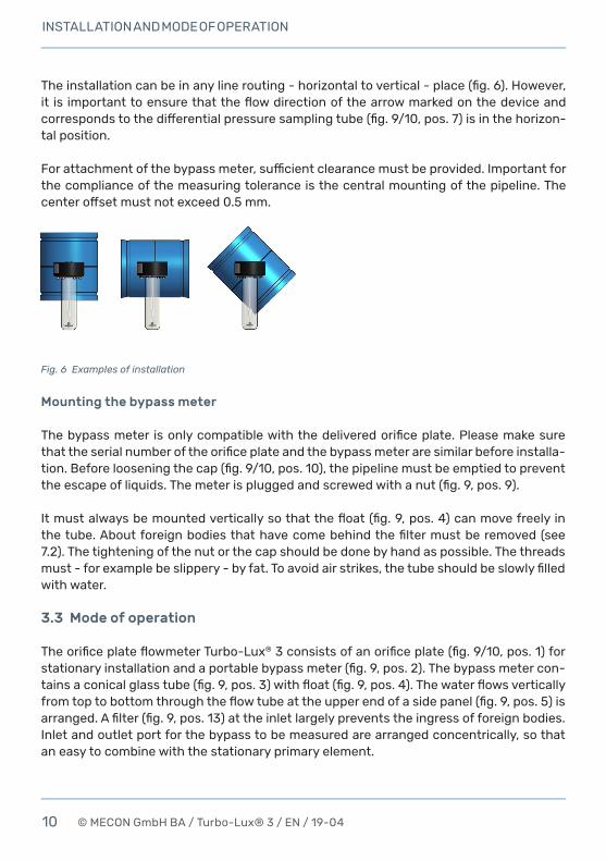
Theinstallationcanbeinanylinerouting-horizontaltovertical-place(fig.6).However,it is importanttoensurethattheflowdirectionofthearrowmarkedonthedeviceandcorrespondstothedifferentialpressuresamplingtube(fig.9/10,pos.7)isinthehorizon-tal position.
Forattachmentofthebypassmeter,sufficientclearancemustbeprovided.Importantforthe compliance of the measuring tolerance is the central mounting of the pipeline. The centeroffsetmustnotexceed0.5mm.
Fig. 6 Examples of installation
Mountingthebypassmeter
Thebypassmeter isonlycompatiblewiththedeliveredorificeplate.Pleasemakesurethattheserialnumberoftheorificeplateandthebypassmeteraresimilarbeforeinstalla-tion.Beforelooseningthecap(fig.9/10,pos.10),thepipelinemustbeemptiedtopreventtheescapeofliquids.Themeterispluggedandscrewedwithanut(fig.9,pos.9).
Itmustalwaysbemountedverticallysothatthefloat(fig.9,pos.4)canmovefreelyinthetube.Aboutforeignbodiesthathavecomebehindthefiltermustberemoved(see7.2). The tightening of the nut or the cap should be done by hand as possible. The threads must-forexamplebeslippery-byfat.Toavoidairstrikes,thetubeshouldbeslowlyfilledwith water.
3.3 Modeofoperation
TheorificeplateflowmeterTurbo-Lux®3consistsofanorificeplate(fig.9/10,pos.1)forstationaryinstallationandaportablebypassmeter(fig.9,pos.2).Thebypassmetercon-tainsaconicalglasstube(fig.9,pos.3)withfloat(fig.9,pos.4).Thewaterflowsverticallyfromtoptobottomthroughtheflowtubeattheupperendofasidepanel(fig.9,pos.5)isarranged.Afilter(fig.9,pos.13)attheinletlargelypreventstheingressofforeignbodies.Inlet and outlet port for the bypass to be measured are arranged concentrically, so that an easy to combine with the stationary primary element.
11© MECON GmbH BA / Turbo-Lux® 3 / EN / 19-04
START-UP
4 START-UP
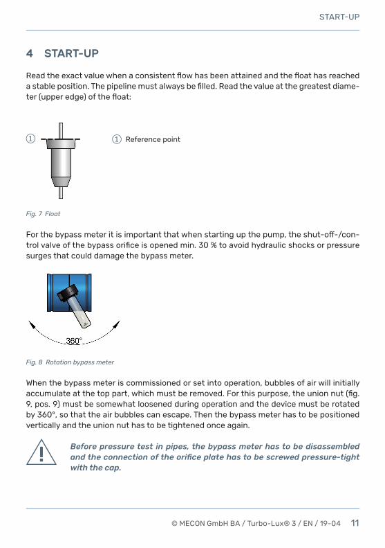
Readtheexactvaluewhenaconsistentflowhasbeenattainedandthefloathasreachedastableposition.Thepipelinemustalwaysbefilled.Readthevalueatthegreatestdiame-ter(upperedge)ofthefloat:
Fig. 7 Float
Forthebypassmeteritisimportantthatwhenstartingupthepump,theshut-off-/con-trolvalveofthebypassorificeisopenedmin.30%toavoidhydraulicshocksorpressuresurges that could damage the bypass meter.
Reference point
Fig. 8 Rotation bypass meter
When the bypass meter is commissioned or set into operation, bubbles of air will initially accumulateatthetoppart,whichmustberemoved.Forthispurpose,theunionnut(fig.9, pos. 9) must be somewhat loosened during operation and the device must be rotated by 360°, so that the air bubbles can escape. Then the bypass meter has to be positioned vertically and the union nut has to be tightened once again.
Before pressure test in pipes, the bypass meter has to be disassembled and the connection of the orifice plate has to be screwed pressure-tight with the cap.
12 © MECON GmbH BA / Turbo-Lux® 3 / EN / 19-04
START-UP
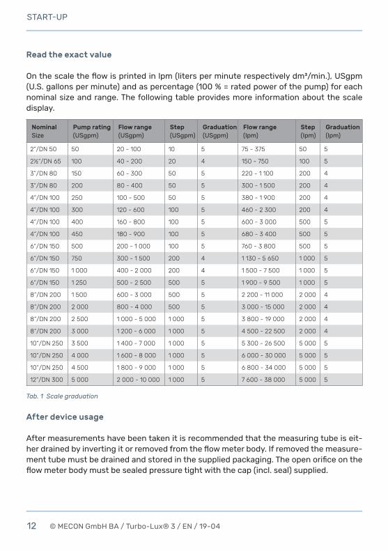
Readtheexactvalue
Onthescaletheflowisprintedinlpm(litersperminuterespectivelydm³/min.),USgpm(U.S.gallonsperminute)andaspercentage(100%=ratedpowerofthepump)foreachnominal size and range. The following table provides more information about the scale display.
NominalSize
Pumprating(USgpm)
Flowrange(USgpm)
Step(USgpm)
Graduation(USgpm)
Flowrange(Ipm)
Step(Ipm)
Graduation(lpm)
2“/DN 50 50 20 - 100 10 5 75 - 375 50 5
2½“/DN 65 100 40 - 200 20 4 150 - 750 100 5
3“/DN 80 150 60 - 300 50 5 220 - 1 100 200 4
3“/DN 80 200 80 - 400 50 5 300 - 1 500 200 4
4“/DN 100 250 100 - 500 50 5 380 - 1 900 200 4
4“/DN 100 300 120 - 600 100 5 460 - 2 300 200 4
4“/DN 100 400 160 - 800 100 5 600 - 3 000 500 5
4“/DN 100 450 180 - 900 100 5 680 - 3 400 500 5
6“/DN 150 500 200 - 1 000 100 5 760 - 3 800 500 5
6“/DN 150 750 300 - 1 500 200 4 1 130 - 5 650 1 000 5
6“/DN 150 1 000 400 - 2 000 200 4 1 500 - 7 500 1 000 5
6“/DN 150 1 250 500 - 2 500 500 5 1 900 - 9 500 1 000 5
8“/DN 200 1 500 600 - 3 000 500 5 2 200 - 11 000 2 000 4
8“/DN 200 2 000 800 - 4 000 500 5 3 000 - 15 000 2 000 4
8“/DN 200 2 500 1 000 - 5 000 1 000 5 3 800 - 19 000 2 000 4
8“/DN 200 3 000 1 200 - 6 000 1 000 5 4 500 - 22 500 2 000 4
10“/DN 250 3 500 1 400 - 7 000 1 000 5 5 300 - 26 500 5 000 5
10“/DN 250 4 000 1 600 - 8 000 1 000 5 6 000 - 30 000 5 000 5
10“/DN 250 4 500 1 800 - 9 000 1 000 5 6 800 - 34 000 5 000 5
12“/DN 300 5 000 2 000 - 10 000 1 000 5 7 600 - 38 000 5 000 5
Tab. 1 Scale graduation
Afterdeviceusage
After measurements have been taken it is recommended that the measuring tube is eit-herdrainedbyinvertingitorremovedfromtheflowmeterbody.Ifremovedthemeasure-menttubemustbedrainedandstoredinthesuppliedpackaging.Theopenorificeontheflowmeterbodymustbesealedpressuretightwiththecap(incl.seal)supplied.
13© MECON GmbH BA / Turbo-Lux® 3 / EN / 19-04
TECHNICAL DATA
5 TECHNICALDATA
Measuringprinciple Orificeplateflowmeterwithvariableflowmeteras indication
Input » Nominal Size
» Pressure limit » Hydrostatically strength/
Pressure strength
2"/DN 50 grooved ends (Ø60.3 mm)2½"/DN 65 grooved ends (Ø73.0 mm)2½"/DN 65 grooved ends (Ø76.1 mm)3"/DN 80 grooved ends (Ø88.9 mm)4"/DN 100 grooved ends (Ø114.3 mm)6"/DN 150 grooved ends (Ø165.1 mm)6"/DN 150 grooved ends (Ø168.3 mm)8"/DN 200 grooved ends (Ø219.1 mm)10"/DN 250 grooved ends (Ø273.0 mm)12"/DN 300 grooved ends (Ø323.9 mm)PN 16 (232 psig)64 bar (928 psig) for 5 min. (FM)40 bar (580 psig) for 5 min. (LPCB)64 bar (928 psig) for 10 min. (VdS)
Measuringaccuracy ±2.0%offullscalevalue(FM)±5.0%ofmeasuredvalue(LPCB)±2.5%offullscalevalue(VdS)
Applicationconditions » Temperature limit » Medium
+4 °C to +50 °C (+39 °F to +122 °F)Water
Design/Material » Orificeplate
2"/DN 50 - 4"/DN 100 6"/DN 150 - 12"/DN 300
» Differentialpressuretube » Float » Bypassorifice » Filter » Seal
Housing tube in stainless steel with turned grooved connection coated steel with rolled grooved connection1)
BrassStainless steelStainless steelStainless steelNBR
Certifications FM Approval 3056052LPCBCertificateNumber1385aVdS G415006
1) coated steel in RAL 5015 optional in stainless steel with rolled grooved connection
14 © MECON GmbH BA / Turbo-Lux® 3 / EN / 19-04
TECHNICAL DATA
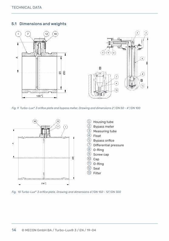
5.1 Dimensionsandweights
Fig. 9 Turbo-Lux® 3 orifice plate and bypass meter, Drawing and dimensions 2“/DN 50 - 4“/DN 100
Fig. 10 Turbo-Lux® 3 orifice plate, Drawing and dimensions 6"/DN 150 - 12"/DN 300
Housing tube Bypass meterMeasuring tubeFloatBypassorificeDifferentialpressureO-RingScrew capCapO-RingSealFilter
15© MECON GmbH BA / Turbo-Lux® 3 / EN / 19-04
TECHNICAL DATA
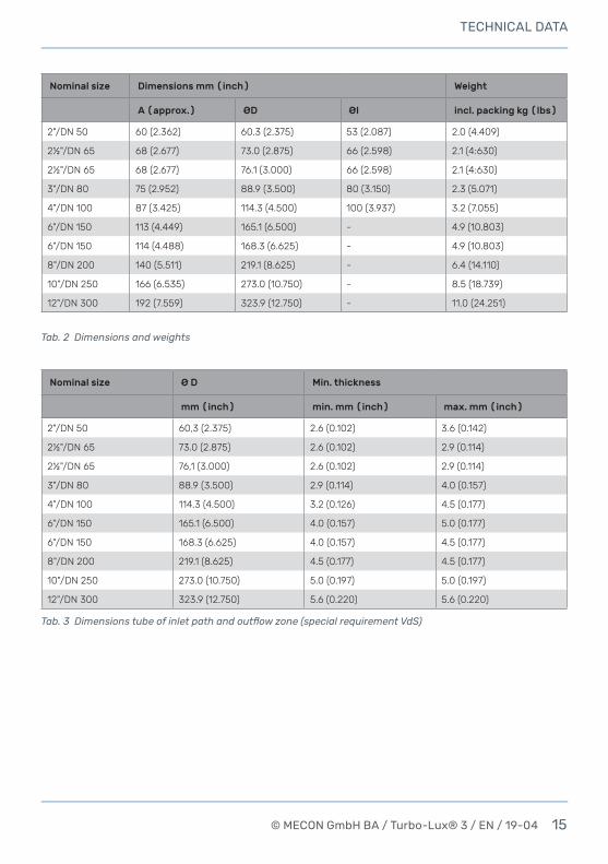
Nominalsize Dimensionsmm(inch) Weight
A(approx.) ØD ØI incl.packingkg(lbs)
2"/DN 50 60 (2.362) 60.3 (2.375) 53 (2.087) 2.0 (4.409)
2½"/DN 65 68 (2.677) 73.0 (2.875) 66 (2.598) 2.1 (4:630)
2½"/DN 65 68 (2.677) 76.1 (3.000) 66 (2.598) 2.1 (4:630)
3"/DN 80 75 (2.952) 88.9 (3.500) 80 (3.150) 2.3 (5.071)
4"/DN 100 87 (3.425) 114.3 (4.500) 100 (3.937) 3.2 (7.055)
6"/DN 150 113 (4.449) 165.1 (6.500) - 4.9 (10.803)
6"/DN 150 114 (4.488) 168.3 (6.625) - 4.9 (10.803)
8"/DN 200 140 (5.511) 219.1 (8.625) - 6.4 (14.110)
10"/DN 250 166 (6.535) 273.0 (10.750) - 8.5 (18.739)
12"/DN 300 192 (7.559) 323.9 (12.750) - 11.0 (24.251)
Nominalsize ØD Min.thickness
mm(inch) min.mm(inch) max.mm(inch)
2"/DN 50 60,3 (2.375) 2.6 (0.102) 3.6 (0.142)
2½"/DN 65 73.0 (2.875) 2.6 (0.102) 2.9 (0.114)
2½"/DN 65 76,1 (3.000) 2.6 (0.102) 2.9 (0.114)
3"/DN 80 88.9 (3.500) 2.9 (0.114) 4.0 (0.157)
4"/DN 100 114.3 (4.500) 3.2 (0.126) 4.5 (0.177)
6"/DN 150 165.1 (6.500) 4.0 (0.157) 5.0 (0.177)
6"/DN 150 168.3 (6.625) 4.0 (0.157) 4.5 (0.177)
8"/DN 200 219.1 (8.625) 4.5 (0.177) 4.5 (0.177)
10"/DN 250 273.0 (10.750) 5.0 (0.197) 5.0 (0.197)
12"/DN 300 323.9 (12.750) 5.6 (0.220) 5.6 (0.220)
Tab. 3 Dimensions tube of inlet path and outflow zone (special requirement VdS)
Tab. 2 Dimensions and weights
16 © MECON GmbH BA / Turbo-Lux® 3 / EN / 19-04
DESCRIPTION CODE
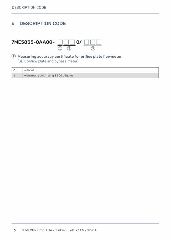
6 DESCRIPTIONCODE
Measuringaccuracycertificatefororificeplateflowmeter (SET: orifice plate and bypass meter)
7ME5835-0AA00- 0/
0 without
1 with (max. pump-rating 3 500 USgpm)

17© MECON GmbH BA / Turbo-Lux® 3 / EN / 19-04
DESCRIPTION CODE
Nominalsizegroovedends
PumpratingUSgpm
Flowrange Approval
USgpm LPM FM LPCB VdS
EB 2"/DN 50 (Ø60.3) 50 20 - 100 75 - 375 X X X
UC 2½"/DN 65 (Ø73.0) 100 40 - 200 150 - 750 X - -
FC 2½"/DN 65 (Ø76.1) 100 40 - 200 150 - 750 X X X
GD 3"/DN 80 (Ø88.9) 150 60 - 300 220 - 1 100 X X X
GE 3"/DN 80 (Ø88.9) 200 80 - 400 300 - 1 500 X X X
HF 4"/DN 100 (Ø114.3) 250 100 - 500 380 - 1 900 X X X
HG 4"/DN 100 (Ø114.3) 300 120 - 600 460 - 2 300 X X X
HH 4"/DN 100 (Ø114.3) 400 160 - 800 600 - 3 000 X X X
HJ 4"/DN 100 (Ø114.3) 450 180 - 900 680 - 3 400 X X X
XK 6"/DN 150 (Ø165.1) 500 200 - 1 000 760 - 3 800 X X X
XL 6"/DN 150 (Ø165.1) 750 300 - 1 500 1 130 - 5 650 X X X
XM 6"/DN 150 (Ø165.1) 1 000 400 - 2 000 1 500 - 7 500 X X X
XN 6"/DN 150 (Ø165.1) 1 250 500 - 2 500 1 900 - 9 500 X X X
KK 6"/DN 150 (Ø168.3) 500 200 - 1 000 760 - 3 800 X X X
KL 6"/DN 150 (Ø168.3) 750 300 – 1 500 1 130 - 5 650 X X X
KM 6"/DN 150 (Ø168.3) 1 000 400 - 2 000 1 500 - 7 500 X X X
KN 6"/DN 150 (Ø168.3) 1 250 500 - 2 500 1 900 - 9 500 X X X
LP 8"/DN 200 (Ø219,1) 1 500 600 - 3 000 2 200 - 11 000 X X X
LQ 8"/DN 200 (Ø219.1) 2 000 800 - 4 000 3 000 - 15 000 X X X
LR 8"/DN 200 (Ø219.1) 2 500 1 000 - 5 000 3 800 - 19 000 X X X
LS 8"/DN 200 (Ø219.1) 3 000 1 200 - 6 000 4 500 - 22 500 X X X*
MT 10"/DN 250 (Ø273.0) 3 500 1 400 - 7 000 5 300 - 26 500 X - -
MU 10"/DN 250 (Ø273.0) 4 000 1 600 - 8 000 6 000 - 30 000 X - -
MV 10"/DN 250 (Ø273.0) 4 500 1 800 - 9 000 6 800 - 34 000 X - -
NW 12"/DN 300 (Ø323.9) 5 000 2 000 - 10 000 7 600 - 38 000 X - -
7ME5835-0AA01- 0 0
Nominalsize/Pumprating
Options
00R Housing tube in colour RAL 3000, option for nominal size 6"/DN 150 to 12"/DN 300
00S Housing tube made in stainless steel, option for nominal size 6"/DN 150 to 12"/DN 300
*VdS-limited flow range up to 10 m/s (corresponds to 20 800 lpm)
BypassFlowmeter(Replacement)
18 © MECON GmbH BA / Turbo-Lux® 3 / EN / 19-04
SERVICE
7 SERVICE
7.1 Storage
Store the emptied device in a dry and dust-free place. Keep away from direct and perma-nent sun and heat. The storage temperature range is -20 to +60 °C (-4 °F to +140 °F). Keep away from direct external load to the device.
7.2 Maintenance
Ifthefilterisblockedbydeposits(fig.9,pos.13)theflowmetermustbereturnedtothemanufacturertobecleanedandtested.EnsurethattheO-ring (fig.9,pos.8)andthe M30x1.5threadoftheorificeplatearelubricatedwithgrease.
7.3 Returningthedevicetothemanufacturer
Allflowmetersweremanufacturedinaccordancewiththehighestqualitystandardsandwere thoroughly tested prior to shipment.
Should you nevertheless need to return a device to MECON GmbH please observe the following points:
7ME5835-0AA01- 0AA0
Replacementcap(incl.gasket)
19© MECON GmbH BA / Turbo-Lux® 3 / EN / 19-04
Attention!
According to the latest waste disposal directives, the owner/customer is responsible for the waste management of hazardous and toxic waste. For reasons of environmental protection and safeguarding the health and sa-fety of our personnel, all devices sent to MECON GmbH to be repaired must be free of toxic and hazardous substances. This also applies to cavities of the devices. If necessary, the customer is kindly requested to neutralize or rinse the devices before returning them to MECON GmbH.
The customer has to confirm this by filling in an appropriate form and to be added to the device, which is available for download on the MECON web-site:
» www.mecon.de/files/daten/downloads/en/Decontamination.pdf
7.4 Disposal
Attention!
For disposal of equipment are the regulations in your country comply.
20 © MECON GmbH BA / Turbo-Lux® 3 / EN / 19-04
MECONGmbHRöntgenstr. 10550169 KerpenGermany
Tel.: +49 (0) 2237 600 06 - 0Fax: +49 (0) 2237 600 06 - 40E-Mail: [email protected]
Web: www.mecon.de


![[MS-VDS-Diff]: Virtual Disk Service (VDS) Protocol · 3 / 349 [MS-VDS-Diff] - v20170601 Virtual Disk Service (VDS) Protocol Copyright © 2017 Microsoft Corporation Release: June 1,](https://img.pdfslide.us/doc/110x75/5ece115ec9f8163d2d78ee85/ms-vds-diff-virtual-disk-service-vds-protocol-3-349-ms-vds-diff-v20170601.jpg)