Embed Size (px)
Citation preview
ST
EP
PIN
G M
OTO
RS
B-1752000-2001 ORIENTAL MOTOR GENERAL CATALOG
Features ·····························································B-176
Standard Type ····················································B-179
TH Geared Type ·················································B-185
List of Motor and Driver Combinations ···············B-190
Wiring Diagrams ·················································B-191
Adjusting the Output Current ······························B-193
ORIENTAL MOTOR GENERAL CATALOG
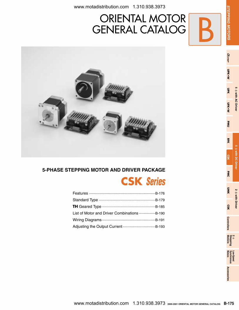
5-PHASE STEPPING MOTOR AND DRIVER PACKAGE
CSK Series
ST
EP
PIN
G M
OTO
RS
UPK
•W
UPK
UFK
•W
PM
URFK
CSK
PM
CU
MK
CSK
Co
ntro
llers
2
Step
pin
gM
oto
rs
Low-Speed
SynchronousM
otorsA
ccessories
5
with
AC
Driver
5
with
DC
Driver
2
with
Driver
www.motadistribution.com 1.310.938.3973
www.motadistribution.com 1.310.938.3973
B-176 2000-2001 ORIENTAL MOTOR GENERAL CATALOG
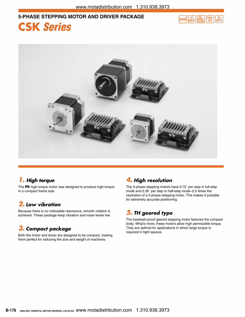
5-PHASE STEPPING MOTOR AND DRIVER PACKAGE
CSK Series
1. High torqueThe PK high torque motor was designed to produce high-torquein a compact frame size.
2. Low vibrationBecause there is no noticeable resonance, smooth rotation isachieved. These package keep vibration and noise levels low.
3. Compact packageBoth the motor and driver are designed to be compact, makingthem perfect for reducing the size and weight of machines.
4. High resolutionThe 5-phase stepping motors have 0.72˚ per step in full-stepmode and 0.36˚ per step in half-step mode–2.5 times theresolution of a 2-phase stepping motor. This makes it possiblefor extremely accurate positioning.
5. TH geared typeThe backlash-proof geared stepping motor features the compactbody: What's more, these motors allow high permissible torque. They are optimal for applications in which large torque isrequired in tight spaces.
PLCDIRECTGEAR
RE- GENER-ATION
PACK-AGE
DCINPUT
www.motadistribution.com 1.310.938.3973
www.motadistribution.com 1.310.938.3973
B-1772000-2001 ORIENTAL MOTOR GENERAL CATALOG
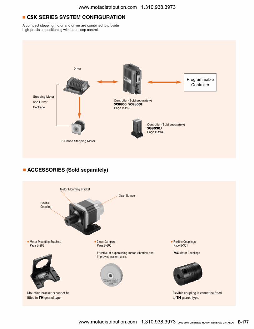
CSK SERIES SYSTEM CONFIGURATIONA compact stepping motor and driver are combined to providehigh-precision positioning with open loop control.
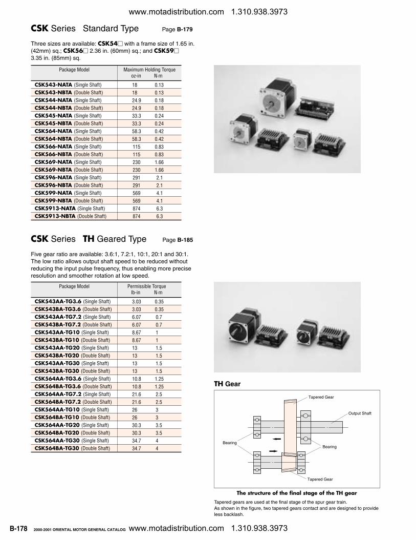
ACCESSORIES (Sold separately)
ProgrammableController
Driver
5-Phase Stepping Motor
Clean DampersPage B-300
Effective at suppressing motor vibration andimproving performance.
Motor Mounting BracketsPage B-298
Flexible CouplingsPage B-301
MC Motor Couplings
Controller (Sold separately)SC8800, SC8800EPage B-260
Controller (Sold separately)SG8030JPage B-264
FlexibleCoupling
Clean Damper
Motor Mounting Bracket
Stepping Motor
and Driver
Package
Mounting bracket is cannot befitted to TH geared type.
Flexible coupling is cannot be fittedto TH geared type.
www.motadistribution.com 1.310.938.3973
www.motadistribution.com 1.310.938.3973
B-178 2000-2001 ORIENTAL MOTOR GENERAL CATALOG
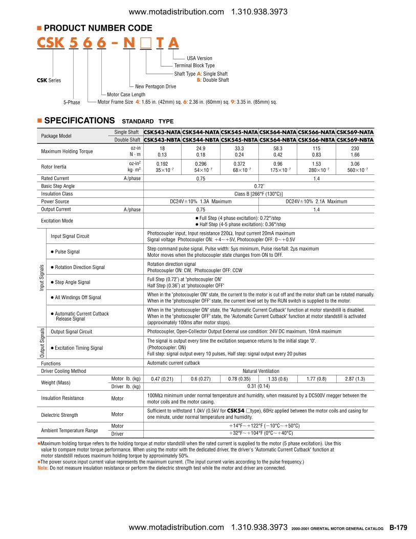
CSK Series Standard Type Page B-179
Three sizes are available: CSK54 with a frame size of 1.65 in.(42mm) sq.; CSK56 2.36 in. (60mm) sq.; and CSK59 3.35 in. (85mm) sq.
CSK Series TH Geared Type Page B-185
Five gear ratio are available: 3.6:1, 7.2:1, 10:1, 20:1 and 30:1.The low ratio allows output shaft speed to be reduced withoutreducing the input pulse frequency, thus enabling more preciseresolution and smoother rotation at low speed.
TH Gear
Tapered gears are used at the final stage of the spur gear train. As shown in the figure, two tapered gears contact and are designed to provideless backlash.
BearingBearing
Tapered Gear
Tapered Gear
Output Shaft
The structure of the final stage of the TH gear
Package Model
CSK543-NATA (Single Shaft)CSK543-NBTA (Double Shaft)CSK544-NATA (Single Shaft)CSK544-NBTA (Double Shaft)CSK545-NATA (Single Shaft)CSK545-NBTA (Double Shaft)CSK564-NATA (Single Shaft)CSK564-NBTA (Double Shaft)CSK566-NATA (Single Shaft)CSK566-NBTA (Double Shaft)CSK569-NATA (Single Shaft)CSK569-NBTA (Double Shaft)CSK596-NATA (Single Shaft)CSK596-NBTA (Double Shaft)CSK599-NATA (Single Shaft)CSK599-NBTA (Double Shaft)CSK5913-NATA (Single Shaft)CSK5913-NBTA (Double Shaft)
18 0.1318 0.1324.9 0.1824.9 0.1833.3 0.2433.3 0.2458.3 0.4258.3 0.42115 0.83115 0.83230 1.66230 1.66291 2.1291 2.1569 4.1569 4.1874 6.3874 6.3
Maximum Holding Torqueoz-in N·m
Package Model
CSK543AA-TG3.6 (Single Shaft)CSK543BA-TG3.6 (Double Shaft)CSK543AA-TG7.2 (Single Shaft)CSK543BA-TG7.2 (Double Shaft)CSK543AA-TG10 (Single Shaft)CSK543BA-TG10 (Double Shaft)CSK543AA-TG20 (Single Shaft)CSK543BA-TG20 (Double Shaft)CSK543AA-TG30 (Single Shaft)CSK543BA-TG30 (Double Shaft)CSK564AA-TG3.6 (Single Shaft)CSK564BA-TG3.6 (Double Shaft)CSK564AA-TG7.2 (Single Shaft)CSK564BA-TG7.2 (Double Shaft)CSK564AA-TG10 (Single Shaft)CSK564BA-TG10 (Double Shaft)CSK564AA-TG20 (Single Shaft)CSK564BA-TG20 (Double Shaft)CSK564AA-TG30 (Single Shaft)CSK564BA-TG30 (Double Shaft)
3.03 0.353.03 0.356.07 0.76.07 0.78.67 18.67 113 1.513 1.513 1.513 1.510.8 1.2510.8 1.2521.6 2.521.6 2.526 326 330.3 3.530.3 3.534.7 434.7 4
lb-in N·mPermissible Torque
www.motadistribution.com 1.310.938.3973
www.motadistribution.com 1.310.938.3973
B-1792000-2001 ORIENTAL MOTOR GENERAL CATALOG
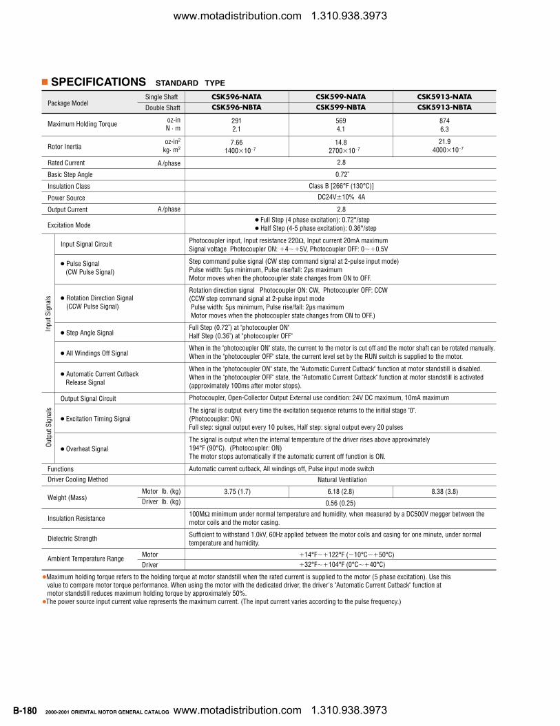
PRODUCT NUMBER CODE
Terminal Block Type
Motor Case Length
CSK Series
Package Model
Maximum Holding Torque
Rotor Inertia
Rated CurrentBasic Step AngleInsulation ClassPower SourceOutput Current
Excitation Mode
Input SignaI Circuit
Pulse Signal
Rotation Direction Signal
Step Angle Signal
All Windings Off Signal
Automatic Current Cutback Release Signal
Output Signal Circuit
Excitation Timing Signal
FunctionsDriver Cooling Method
Weight (Mass)
Insulation Resistance
Dielectric Strength
Ambient Temperature Range
SPECIFICATIONS STANDARD TYPE
Single ShaftDouble Shaft
oz-inN · m
oz-in2
kg· m2
A /phase
A /phase
Full Step (4 phase excitation): 0.72°/step Half Step (4-5 phase excitation): 0.36°/step
Photocoupler input, Input resistance 220Ω, Input current 20mA maximumSignal voltage Photocoupler ON: 45V, Photocoupler OFF: 00.5V
Step command pulse signal, Pulse width: 5µs minimum, Pulse rise/fall: 2µs maximumMotor moves when the photocoupler state changes from ON to OFF.
Rotation direction signalPhotocoupler ON: CW, Photocoupler OFF: CCW
Full Step (0.72˚) at "photocoupler ON"Half Step (0.36˚) at "photocoupler OFF"
When in the "photocoupler ON" state, the current to the motor is cut off and the motor shaft can be rotated manually.When in the "photocoupler OFF" state, the current level set by the RUN switch is supplied to the motor.
When in the "photocoupler ON" state, the "Automatic Current Cutback" function at motor standstill is disabled.When in the "photocoupler OFF" state, the "Automatic Current Cutback" function at motor standstill is activated(approximately 100ms after motor stops).
PhotocoupIer, Open-CoIIector Output External use condition: 24V DC maximum, 10mA maximum
The signal is output every time the excitation sequence returns to the initial stage "0". (Photocoupler: ON)Full step: signal output every 10 pulses, Half step: signal output every 20 pulses
Automatic current cutback
Natural Ventilation
100MΩ minimum under normal temperature and humidity, when measured by a DC500V megger between themotor coils and the motor casing.
Sufficient to withstand 1.0kV (0.5kV for CSK54 type), 60Hz applied between the motor coils and casing forone minute, under normal temperature and humidity.
14°F122°F (10°C50°C)32°F104°F (0°C40°C)
0.75 1.4
Motor lb. (kg)Driver lb. (kg)
Motor
Motor
MotorDriver
Maximum holding torque refers to the holding torque at motor standstill when the rated current is supplied to the motor (5 phase excitation). Use thisvalue to compare motor torque performance. When using the motor with the dedicated driver, the driver's "Automatic Current Cutback" function atmotor standstill reduces maximum holding torque by approximately 50%.
The power source input current value represents the maximum current. (The input current varies according to the pulse frequency.)Note: Do not measure insulation resistance or perform the dielectric strength test while the motor and driver are connected.
USA Version
Motor Frame Size 4: 1.65 in. (42mm) sq. 6: 2.36 in. (60mm) sq. 9: 3.35 in. (85mm) sq.
Shaft Type A: Single ShaftB: Double Shaft
CSK 5 6 6 - N T A
New Pentagon Drive
5-Phase
0.72˚Class B [266°F (130°C)]
1.33 (0.6)0.31 (0.14)
1.77 (0.8) 2.87 (1.3)0.47 (0.21) 0.6 (0.27) 0.78 (0.35)
CSK564-NATACSK564-NBTA
58.30.42
0.96175107
CSK566-NATACSK566-NBTA
1150.83
1.53280107
CSK569-NATACSK569-NBTA
2301.66
3.06560107
CSK543-NATACSK543-NBTA
180.13
0.19235107
CSK544-NATACSK544-NBTA
24.90.18
0.29654107
CSK545-NATACSK545-NBTA
33.30.24
0.37268107
0.75 1.4
DC24V10% 1.3A Maximum DC24V10% 2.1A Maximum
Inpu
t Sig
nals
Outp
ut S
igna
ls
www.motadistribution.com 1.310.938.3973
www.motadistribution.com 1.310.938.3973
B-180 2000-2001 ORIENTAL MOTOR GENERAL CATALOG
Package Model
Maximum Holding Torque
Rotor Inertia
Rated Current
Basic Step Angle
Insulation Class
Power Source
Output Current
Excitation Mode
Input Signal Circuit
Pulse Signal(CW Pulse Signal)
Rotation Direction Signal(CCW Pulse Signal)
Step Angle Signal
All Windings Off Signal
Automatic Current CutbackRelease Signal
Output Signal Circuit
Excitation Timing Signal
Overheat Signal
FunctionsDriver Cooling Method
Weight (Mass)
Insulation Resistance
Dielectric Strength
Ambient Temperature Range
CSK596-NATACSK596-NBTA
2912.1
7.661400107
Full Step (4 phase excitation): 0.72°/step Half Step (4-5 phase excitation): 0.36°/step
Photocoupler input, Input resistance 220Ω, Input current 20mA maximumSignal voltage Photocoupler ON: 45V, Photocoupler OFF: 00.5V
Step command pulse signal (CW step command signal at 2-pulse input mode)Pulse width: 5µs minimum, Pulse rise/fall: 2µs maximumMotor moves when the photocoupler state changes from ON to OFF.
Rotation direction signal Photocoupler ON: CW, Photocoupler OFF: CCW(CCW step command signal at 2-pulse input modePulse width: 5µs minimum, Pulse rise/fall: 2µs maximumMotor moves when the photocoupler state changes from ON to OFF.)
Full Step (0.72˚) at "photocoupler ON"Half Step (0.36˚) at "photocoupler OFF"
When in the "photocoupler ON" state, the current to the motor is cut off and the motor shaft can be rotated manually.When in the "photocoupler OFF" state, the current level set by the RUN switch is supplied to the motor.
When in the "photocoupler ON" state, the "Automatic Current Cutback" function at motor standstill is disabled.When in the "photocoupler OFF" state, the "Automatic Current Cutback" function at motor standstill is activated(approximately 100ms after motor stops).
Photocoupler, Open-Collector Output External use condition: 24V DC maximum, 10mA maximum
The signal is output every time the excitation sequence returns to the initial stage "0". (Photocoupler: ON)Full step: signal output every 10 pulses, Half step: signal output every 20 pulses
The signal is output when the internal temperature of the driver rises above approximately 194°F (90°C). (Photocoupler: ON)The motor stops automatically if the automatic current off function is ON.
Automatic current cutback, All windings off, Pulse input mode switch
Natural Ventilation
100MΩ minimum under normal temperature and humidity, when measured by a DC500V megger between themotor coils and the motor casing.
Sufficient to withstand 1.0kV, 60Hz applied between the motor coils and casing for one minute, under normaltemperature and humidity.
14°F122°F (10°C50°C)32°F104°F (0°C40°C)
Maximum holding torque refers to the holding torque at motor standstill when the rated current is supplied to the motor (5 phase excitation). Use thisvalue to compare motor torque performance. When using the motor with the dedicated driver, the driver's "Automatic Current Cutback" function atmotor standstill reduces maximum holding torque by approximately 50%.
The power source input current value represents the maximum current. (The input current varies according to the pulse frequency.)
0.72˚
Class B [266°F (130°C)]
CSK599-NATACSK599-NBTA
5694.1
14.82700107
CSK5913-NATACSK5913-NBTA
8746.3
21.94000107
2.8
2.8
DC24V10% 4A
Inpu
t Sig
nals
Outp
ut S
igna
ls
Single Shaft
Double Shaft
oz-inN · m
oz-in2
kg· m2
A /phase
A /phase
3.75 (1.7) 6.18 (2.8) 8.38 (3.8)Motor lb. (kg)Driver lb. (kg)
MotorDriver
0.56 (0.25)
SPECIFICATIONS STANDARD TYPE
www.motadistribution.com 1.310.938.3973
www.motadistribution.com 1.310.938.3973
B-1812000-2001 ORIENTAL MOTOR GENERAL CATALOG
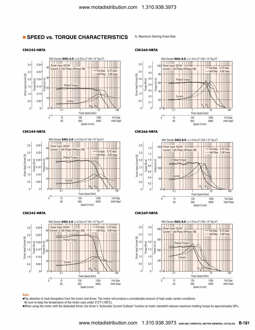
SPEED vs. TORQUE CHARACTERISTICS
CSK543-NBTA
CSK544-NBTA
CSK545-NBTA
0.1 1 10 100
Torq
ue [ o
z-in
]
40
30
20
10
0
Pulse Speed [kHz]
Torq
ue [ N
·m]
0.30
0.25
0.20
0.15
0.10
0.05
0
3.0
2.5
2.0
1.5
1.0
0.5
0
Drive
r Inp
ut C
urre
nt [ A
]
With Damper D4CL-5.0: JL=0.22oz-in2 (4010–7kg·m2)
Speed [r/min]
12(6)
0 120(60)
1200(600)
Full Step(Half Step)
Pullout Torque
Current
fs
Power Input: DC24VCurrent: 0.75A /Phase (4Phases ON)
Full Step 0.72˚/stepHalf Step 0.36˚/step
fs
CSK564-NBTA
CSK566-NBTA
CSK569-NBTA
0.1 1 10 100
Torq
ue [ o
z-in
]
100
80
60
40
20
0
Pulse Speed [kHz]
Torq
ue [ N
·m]
3.0
2.5
2.0
1.5
1.0
0.5
0
Drive
r Inp
ut C
urre
nt [ A
]
With Damper D6CL-8.0: JL=1.01oz-in2 (18510–7kg·m2)
Speed [r/min]
12(6)
0 120(60)
1200(600)
Full Step(Half Step)
Current
Power Input: DC24VCurrent: 1.4A /Phase (4Phases ON) Full Step 0.72˚/step
Half Step 0.36˚/step
fsfs
0.7
0.6
0.5
0.4
0.3
0.2
0.1
0
Pullout Torque
0.1 1 10 100
Torq
ue [ o
z-in
]
200
150
100
50
0
Pulse Speed [kHz]
Torq
ue [ N
·m]
3.0
2.5
2.0
1.5
1.0
0.5
0
Drive
r Inp
ut C
urre
nt [ A
]With Damper D6CL-8.0: JL=1.01oz-in2 (18510–7kg·m2)
Speed [r/min]
12(6)
0 120(60)
1200(600)
Full Step(Half Step)
Current
Power Input: DC24VCurrent: 1.4A /Phase (4Phases ON) Full Step 0.72˚/step
Half Step 0.36˚/step
fsfs
1.4
1.2
1.0
0.8
0.6
0.4
0.2
0
Pullout Torque
0.1 1 10 100
Torq
ue [ o
z-in
]
400
300
200
100
0
Pulse Speed [kHz]
Torq
ue [ N
·m]
3.0
2.5
2.0
1.5
1.0
0.5
0
Drive
r Inp
ut C
urre
nt [ A
]
With Damper D6CL-8.0: JL=1.01oz-in2 (18510–7kg·m2)
Speed [r/min]
12(6)
0 120(60)
1200(600)
Full Step(Half Step)
Current
Power Input: DC24VCurrent: 1.4A /Phase (4Phases ON) Full Step 0.72˚/step
Half Step 0.36˚/step
fsfs
3.0
2.5
2.0
1.5
1.0
0.5
0
Pullout Torque
Note: Pay attention to heat dissipation from the motor and driver. The motor will produce a considerable amount of heat under certain conditions.
Be sure to keep the temperature of the motor case under 212˚F (100˚C).When using the motor with the dedicated driver, the driver's "Automatic Current Cutback" function at motor standstill reduces maximum holding torque by approximately 50%.
fs: Maximum Starting Pulse Rate
www.motadistribution.com 1.310.938.3973
www.motadistribution.com 1.310.938.3973
B-182 2000-2001 ORIENTAL MOTOR GENERAL CATALOG
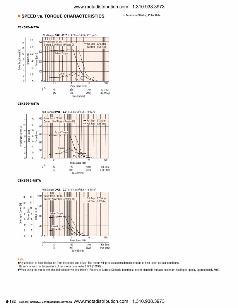
SPEED vs. TORQUE CHARACTERISTICS
CSK596-NBTA
CSK599-NBTA
CSK5913-NBTA
0.1 1 10 100
Torq
ue [ o
z-in
]
400
300
200
100
0
Pulse Speed [kHz]
Torq
ue [ N
·m]
14
12
10
8
6
4
2
0
Drive
r Inp
ut C
urre
nt [ A
]
With Damper D9CL-12.7: JL=4.76oz-in2 (87010–7kg·m2)
Speed [r/min]
12(6)
0 120(60)
1200(600)
Full Step(Half Step)
Current
Power Input: DC24VCurrent: 2.8A /Phase (4Phases ON) Full Step 0.72˚/step
Half Step 0.36˚/step
fsfs
3.0
2.5
2.0
1.5
1.0
0.5
0
Pullout Torque
0.1 1 10 100
Torq
ue [ o
z-in
]
1000
800
600
400
200
0
Pulse Speed [kHz]
Torq
ue [ N
·m]
14
12
10
8
6
4
2
0
Drive
r Inp
ut C
urre
nt [ A
]
With Damper D9CL-12.7: JL=4.76oz-in2 (87010–7kg·m2)
Speed [r/min]
12(6)
0 120(60)
1200(600)
Full Step(Half Step)
Current
Power Input: DC24VCurrent: 2.8A /Phase (4Phases ON) Full Step 0.72˚/step
Half Step 0.36˚/step
fsfs
7
6
5
4
3
2
1
0
Pullout Torque
0.1 1 10 100
Torq
ue [ o
z-in
]
2000
1500
1000
500
0
Pulse Speed [kHz]
Torq
ue [ N
·m]
14
12
10
8
6
4
2
0
Drive
r Inp
ut C
urre
nt [ A
]
With Damper D9CL-12.7: JL=4.76oz-in2 (87010–7kg·m2)
Speed [r/min]
12(6)
0 120(60)
1200(600)
Full Step(Half Step)
Current
Power Input: DC24VCurrent: 2.8A /Phase (4Phases ON) Full Step 0.72˚/step
Half Step 0.36˚/step
fs
14
12
10
8
6
4
2
0
Pullout Torque
Note: Pay attention to heat dissipation from the motor and driver. The motor will produce a considerable amount of heat under certain conditions.
Be sure to keep the temperature of the motor case under 212˚F (100˚C).When using the motor with the dedicated driver, the driver's "Automatic Current Cutback" function at motor standstill reduces maximum holding torque by approximately 50%.
fs: Maximum Starting Pulse Rate
www.motadistribution.com 1.310.938.3973
www.motadistribution.com 1.310.938.3973
B-1832000-2001 ORIENTAL MOTOR GENERAL CATALOG
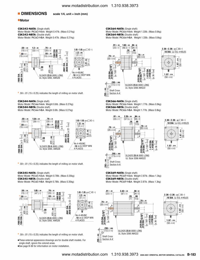
DIMENSIONS scale 1/4, unit = inch (mm)
Motor
CSK543-NATA (Single shaft)Motor Model: PK543-NAA Weight 0.47lb. (Mass 0.21kg)CSK543-NBTA (Double shaft)Motor Model: PK543-NBA Weight 0.47lb. (Mass 0.21kg)
CSK564-NATA (Single shaft)Motor Model: PK564-NAA Weight 1.33lb. (Mass 0.6kg)CSK564-NBTA (Double shaft)Motor Model: PK564-NBA Weight 1.33lb. (Mass 0.6kg)
.59.01 (150.25) indicates the length of milling on motor shaft.Shaft CrossSection A-A'
A
A'
A
A'
UL Style 3266 AWG225LEADS 23.6 (600) LONG
.295.006
.295
.0
06( 7
.5
0.15
)
90˚
.28 .062.362.36.04 (601)
1.97.014
(500.35)
1.97
.0
14
.18 DIA. ( 4.5), 4 HOLES
(231).91.04
(46.51)1.83.04 .94.04
(241)
(7) (1.5).79.01(200.25)
(200.25).79.01
( 7.
937
0.01
5)0
( 7.
937
0.01
5)0
.312
5 DI
A..3
119
DIA.
(7.50.15)
.312
5 DI
A..3
119
DIA.
( 36
0.
039)
0
.1.4
173
DIA.
.1.4
158
DIA.
( 50
0.35
)
[5/1
6"]
[5/1
6"]
UL Style 3265, AWG265LEADS 23.6 (600) LONG
.08(2)
.590.1(150.25)
(151).59.04
(331)1.3.04 .79.04
.177
.0
06( 4
.5
0.15
)
.196
8 DI
A..1
964
DIA .
( 5
0.
012)
0
(201)
(150.25).59.01
.866
1 DI
A..8
648
DIA .
( 2
20.
033)
0
.177
.0
06( 4
.5
0.15
).1
968
DIA
.196
4 DI
A(
5
0.01
2)0
No.4-40UNC .18 (4.5) DEEP MIN4 PLACES
1.651.650.4 (421)1.22.004
(310.1)
1.22
.0
04
(31
0.1 )
CSK544-NATA (Single shaft)Motor Model: PK544-NAA Weight 0.6lb. (Mass 0.27kg)CSK544-NBTA (Double shaft)Motor Model: PK544-NBA Weight 0.6lb. (Mass 0.27kg)
.59.01 (150.25) indicates the length of milling on motor shaft.
UL Style 3265, AWG265LEADS 23.6 (600) LONG
.08(2)
.590.1(150.25)
(151).59.04
(391)1.54.04 .79.04
.177
.0
06( 4
.5
0.15
)
.196
8 DI
A..1
964
DIA.
( 5
0.
012)
0
(201)
(150.25).59.01
.866
1 DI
A..8
648
DIA.
( 2
20.
033)
0
.177
.0
06( 4
.5
0.15
).1
968
DIA
.196
4 DI
A(
5
0.01
2)0
No.4-40UNC .18 (4.5) DEEP MIN4 PLACES
1.651.650.4 (421)1.22.004
(310.1)
1.22
.0
04
(31
0.1 )
Shaft CrossSection A-A'
A
A'
A
A'
UL Style 3266 AWG225LEADS 23.6 (600) LONG
.295.006
.295
.0
06( 7
.5
0.15
)
90˚
.28 .062.362.36.04 (601)
1.97.014
(500.35)
1.97
.0
14
.18 DIA. ( 4.5), 4 HOLES
(231).91.04
(57.51)2.26.04 .94.04
(241)
(7) (1.5).79.01(200.25)
(200.25).79.01
( 7.
937
0.01
5)0
( 7.
937
0.01
5)0
.312
5 DI
A..3
119
DIA.
(7.50.15)
.312
5 DI
A..3
119
DIA.
( 36
0.
039)
0
.1.4
173
DIA.
.1.4
158
DIA.
( 50
0.35
)
[5/1
6"]
[5/1
6"]
UL Style 3265, AWG265LEADS 23.6 (600) LONG
.08(2)
.590.1(150.25)
(151).59.04
(471)1.85.04 .79.04
.177
.0
06( 4
.5
0.15
)
.196
8 DI
A..1
964
DIA.
( 5
0.
012)
0
(201)
(150.25).59.01
.866
1 DI
A..8
648
DIA.
( 2
20.
033)
0
.177
.0
06( 4
.5
0.15
).1
968
DIA
.196
4 DI
A(
5
0.01
2)0
No.4-40UNC .18 (4.5) DEEP MIN4 PLACES
1.651.650.4 (421)1.22.004
(310.1)
1.22
.0
04
(31
0.1 )
These external appearance drawings are for double shaft models. Forsingle shaft, ignore the colored areas.
See page B-36 for information on motor installation.
CSK545-NATA (Single shaft)Motor Model: PK545-NAA Weight 0.78lb. (Mass 0.35kg)CSK545-NBTA (Double shaft)Motor Model: PK545-NBA Weight 0.78lb. (Mass 0.35kg)
CSK569-NATA (Single shaft)Motor Model: PK569-NAA Weight 2.87lb. (Mass 1.3kg)CSK569-NBTA (Double shaft)Motor Model: PK569-NBA Weight 2.87lb. (Mass 1.3kg)
.59.01 (150.25) indicates the length of milling on motor shaft.Shaft CrossSection A-A'
A
A'
A
A'
UL Style 3266 AWG225LEADS 23.6 (600) LONG
.295.006
.295
.0
06( 7
.5
0.15
)
90˚
.28 .062.362.36.04 (601)
1.97.014
(500.35)
1.97
.0
14
.18 DIA. ( 4.5), 4 HOLES
(231).91.04
(871)3.43.04 .94.04
(241)
(7) (1.5).79.01(200.25)
(200.25).79.01
( 7.
937
0.01
5)0
( 7.
937
0.01
5)0
.312
5 DI
A..3
119
DIA.
(7.50.15)
.312
5 DI
A..3
119
DIA.
( 3
60.
039)
0
.1.4
173
DIA.
.1.4
158
DIA.
( 50
0.35
)
[5/1
6"]
[5/1
6"]
CSK566-NATA (Single shaft)Motor Model: PK566-NAA Weight 1.77lb. (Mass 0.8kg)CSK566-NBTA (Double shaft)Motor Model: PK566-NBA Weight 1.77lb. (Mass 0.8kg)
www.motadistribution.com 1.310.938.3973
www.motadistribution.com 1.310.938.3973
B-184 2000-2001 ORIENTAL MOTOR GENERAL CATALOG
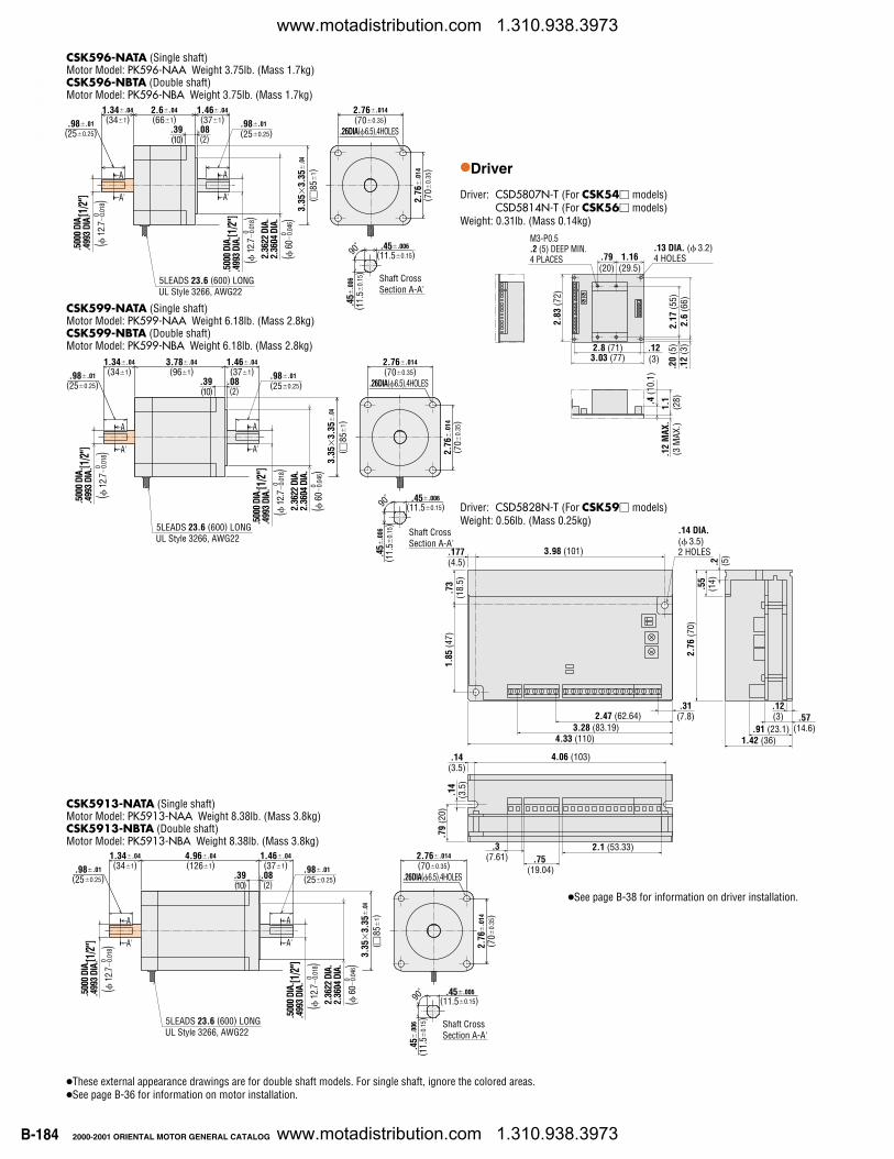
Driver: CSD5807N-T (For CSK54 models)CSD5814N-T (For CSK56 models)
Weight: 0.31lb. (Mass 0.14kg)
Driver: CSD5828N-T (For CSK59 models)Weight: 0.56lb. (Mass 0.25kg)
.12
MAX
.(3
MAX
.)
2.83
(72)
1.16(29.5)
.79(20)
.20
(5)
.12
(3)
.4 (1
0.1)
M3-P0.5 .2 (5) DEEP MIN. 4 PLACES
.13 DIA. ( 3.2)4 HOLES
2.6
(66)
2.17
(55)
.12(3)3.03 (77)
2.8 (71)
1.1
(28)
These external appearance drawings are for double shaft models. For single shaft, ignore the colored areas.See page B-36 for information on motor installation.
CSK596-NATA (Single shaft)Motor Model: PK596-NAA Weight 3.75lb. (Mass 1.7kg)CSK596-NBTA (Double shaft)Motor Model: PK596-NBA Weight 3.75lb. (Mass 1.7kg)
CSK5913-NATA (Single shaft)Motor Model: PK5913-NAA Weight 8.38lb. (Mass 3.8kg)CSK5913-NBTA (Double shaft)Motor Model: PK5913-NBA Weight 8.38lb. (Mass 3.8kg)
[1/2
"]
A
A'
UL Style 3266, AWG22
.45
.006
( 11.
50.
15)
90˚
2.6.04 1.46.04
.39 .08
1.34.04
2.76
.0
14( 7
00.
35)
2.76.014
(700.35).26DIA(6.5),4HOLES
(85
1)A
A'
.98.01.98.01 (661) (371)
(10) (2)
(341)(250.25)(250.25)
( 1
2.7
0.01
8)0
.500
0 DI
A..4
993
DIA.
( 1
2.7
0.01
8)0
.500
0 DI
A..4
993
DIA.
( 60
0.
046)
0
2.36
22 D
IA.
2.36
04 D
IA.
5LEADS 23.6 (600) LONG
3.35
3.
35
.04
Shaft CrossSection A-A'
.45.006(11.50.15)
[1/2
"]
A
A'
UL Style 3266, AWG22
.45
.006
( 11.
50.
15)
90˚
4.96.04 1.46.04
.39 .08
1.34.04
2.76
.0
14( 7
00.
35)
2.76.014
(700.35).26DIA(6.5),4HOLES
(85
1)A
A'
.98.01.98.01 (1261) (371)
(10) (2)
(341)(250.25)(250.25)
( 1
2.7
0.01
8)0
.500
0 DI
A..4
993
DIA.
( 1
2.7
0.01
8 )0
.500
0 DI
A..4
993
DIA.
( 6
00.
046)
0
2.36
22 D
IA.
2.36
04 D
IA.
5LEADS 23.6 (600) LONG
3.35
3.
35
.04
Shaft CrossSection A-A'
.45.006(11.50.15)
[1/2
"]
[1/2
"]
Driver
See page B-38 for information on driver installation.
.14
(3.5
)
.14(3.5)
4.06 (103)
1.85
(47)
.177(4.5)
3.98 (101)
4.33 (110)
.12(3) .57
(14.6)
.73
(18.
5)
.79
(20)
1.42 (36)
.31(7.8)2.47 (62.64)
3.28 (83.19).2
(5
)
.55
(14)
2.76
(70)
2.1 (53.33).75
(19.04)
.3 (7.61)
.91 (23.1)
.14 DIA.( 3.5)2 HOLES
CSK599-NATA (Single shaft)Motor Model: PK599-NAA Weight 6.18lb. (Mass 2.8kg)CSK599-NBTA (Double shaft)Motor Model: PK599-NBA Weight 6.18lb. (Mass 2.8kg)
[1/2
"]
A
A'
UL Style 3266, AWG22
.45
.006
( 11.
50.
15)
90˚
3.78.04 1.46.04
.39 .08
1.34.04
2.76
.0
14( 7
00.
35)
2.76.014
(700.35).26DIA(6.5),4HOLES
(85
1)A
A'
.98.01.98.01 (961) (371)
(10) (2)
(341)(250.25)(250.25)
( 1
2.7
0.01
8)0
.500
0 DI
A..4
993
DIA.
( 1
2.7
0.01
8)0
.500
0 DI
A..4
993
DIA.
( 60
0.
046)
0
2.36
22 D
IA.
2.36
04 D
IA.
5LEADS 23.6 (600) LONG
3.35
3.
35
.04
Shaft CrossSection A-A'
.45.006(11.50.15)
[1/2
"]
ST
EP
PIN
G M
OTO
RS
www.motadistribution.com 1.310.938.3973
www.motadistribution.com 1.310.938.3973
B-1852000-2001 ORIENTAL MOTOR GENERAL CATALOG
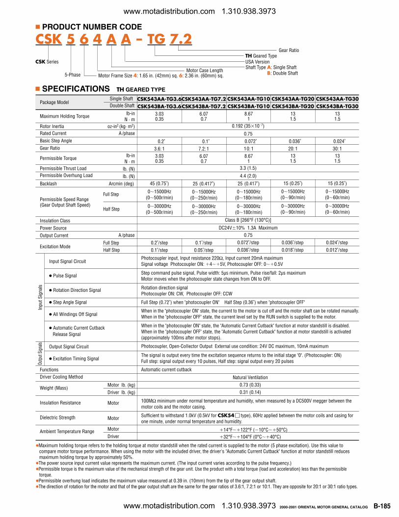
CSK543AA-TG30CSK543BA-TG30
131.5
0.024˚30: 1131.5
15 (0.25˚)
015000Hz(060r/min)
030000Hz(060r/min)
0.024˚/step0.012˚/step
CSK543AA-TG10CSK543BA-TG10
8.671
0.072˚10: 18.67
1
25 (0.417˚)
015000Hz(0180r/min)
030000Hz(0180r/min)
Package Model
Maximum Holding Torque
Rotor InertiaRated CurrentBasic Step AngleGear Ratio
Permissible Torque
Permissible Thrust LoadPermissible Overhung Load
Backlash
Permissible Speed Range(Gear Output Shaft Speed)
Insulation ClassPower SourceOutput Current
Excitation Mode
Input SignaI Circuit
Pulse Signal
Rotation Direction Signal
Step Angle Signal
All Windings Off Signal
Automatic Current Cutback Release Signal
Output Signal Circuit
Excitation Timing Signal
FunctionsDriver Cooling Method
Weight (Mass)
Insulation Resistance
Dielectric Strength
Ambient Temperature Range
Single ShaftDouble Shaft
lb-inN · m
oz-in2 (kg· m2)A /phase
lb-inN · m
lb. (N)lb. (N)
Arcmin (deg)
CSK543AA-TG7.2CSK543BA-TG7.2
6.070.7
0.1˚7.2: 16.070.7
25 (0.417˚)
015000Hz(0250r/min)
030000Hz(0250r/min)
CSK543AA-TG3.6CSK543BA-TG3.6
3.030.35
0.2˚3.6: 13.030.35
45 (0.75˚)
015000Hz(0500r/min)
030000Hz(0500r/min)
Motor lb. (kg)Driver lb. (kg)
Motor
Motor
MotorDriver
Class B [266°F (130°C)]
A /phase
Full StepHalf Step
0.1˚/step0.05˚/step
0.2˚/step0.1˚/step
0.072˚/step0.036˚/step
0.036˚/step0.018˚/step
Full Step
Half Step
CSK543AA-TG20CSK543BA-TG20
131.5
0.036˚20: 1131.5
15 (0.25˚)
015000Hz(090r/min)
030000Hz(090r/min)
DC24V10% 1.3A Maximum0.75
3.3 (1.5)
4.4 (2.0)
0.192 (35107)
0.75
Inpu
t Sig
nals
Outp
ut S
ignals
Maximum holding torque refers to the holding torque at motor standstill when the rated current is supplied to the motor (5 phase excitation). Use this value tocompare motor torque performance. When using the motor with the included driver, the driver's "Automatic Current Cutback" function at motor standstill reducesmaximum holding torque by approximately 50%.
The power source input current value represents the maximum current. (The input current varies according to the pulse frequency.)Permissible torque is the maximum value of the mechanical strength of the gear unit. Use the product with a total torque (load and acceleration) less than the permissible
torque.Permissible overhung load indicates the maximum value measured at 0.39 in. (10mm) from the tip of the gear output shaft.The direction of rotation for the motor and that of the gear output shaft are the same for the gear ratios of 3.6:1, 7.2:1 or 10:1. They are opposite for 20:1 or 30:1 ratio types.
Photocoupler input, Input resistance 220Ω, Input current 20mA maximumSignal voltage Photocoupler ON: 45V, Photocoupler OFF: 00.5V
Step command pulse signal, Pulse width: 5µs minimum, Pulse rise/fall: 2µs maximumMotor moves when the photocoupler state changes from ON to OFF.
Rotation direction signal Photocoupler ON: CW, Photocoupler OFF: CCW
Full Step (0.72˚) when "photocoupler ON" Half Step (0.36˚) when "photocoupler OFF"
When in the "photocoupler ON" state, the current to the motor is cut off and the motor shaft can be rotated manually.When in the "photocoupler OFF" state, the current level set by the RUN switch is supplied to the motor.
When in the "photocoupler ON" state, the "Automatic Current Cutback" function at motor standstill is disabled.When in the "photocoupler OFF" state, the "Automatic Current Cutback" function at motor standstill is activated(approximately 100ms after motor stops).
PhotocoupIer, Open-CoIIector Output External use condition: 24V DC maximum, 10mA maximum
The signal is output every time the excitation sequence returns to the initial stage "0". (Photocoupler: ON)Full step: signal output every 10 pulses, Half step: signal output every 20 pulses
Automatic current cutback
Natural Ventilation0.73 (0.33)0.31 (0.14)
100MΩ minimum under normal temperature and humidity, when measured by a DC500V megger between themotor coils and the motor casing.
Sufficient to withstand 1.0kV (0.5kV for CSK54 type), 60Hz applied between the motor coils and casing forone minute, under normal temperature and humidity.
14°F122°F (10°C50°C)32°F104°F (0°C40°C)
PRODUCT NUMBER CODE
USA Version
Motor Case Length
CSK Series
Motor Frame Size 4: 1.65 in. (42mm) sq. 6: 2.36 in. (60mm) sq.
Shaft Type A: Single ShaftB: Double Shaft
CSK 5 6 4 A A - TG 7.2
5-Phase
SPECIFICATIONS TH GEARED TYPE
Gear RatioTH Geared Type
www.motadistribution.com 1.310.938.3973
www.motadistribution.com 1.310.938.3973
B-186 2000-2001 ORIENTAL MOTOR GENERAL CATALOG
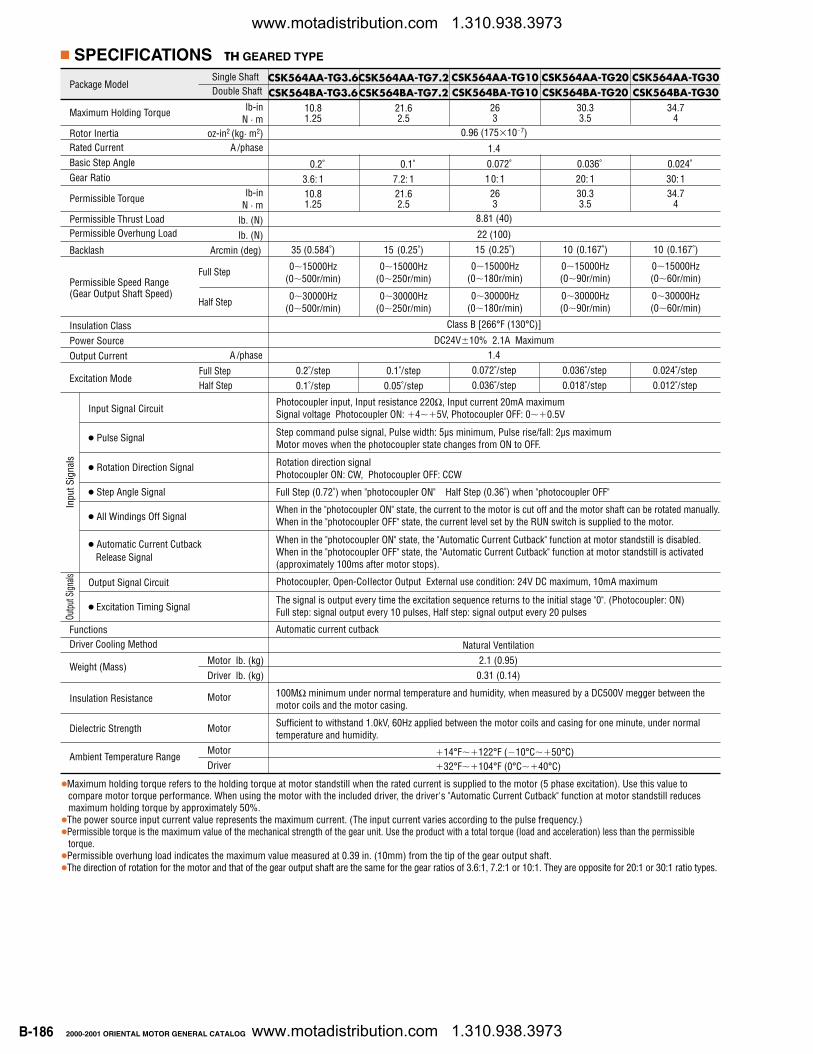
CSK564AA-TG30CSK564BA-TG30
34.74
0.024˚30: 134.7
4
10 (0.167˚)
015000Hz(060r/min)
030000Hz(060r/min)
0.024˚/step0.012˚/step
CSK564AA-TG10CSK564BA-TG10
263
0.072˚10: 1
263
15 (0.25˚)
015000Hz(0180r/min)
030000Hz(0180r/min)
Package Model
Maximum Holding Torque
Rotor InertiaRated CurrentBasic Step AngleGear Ratio
Permissible Torque
Permissible Thrust LoadPermissible Overhung Load
Backlash
Permissible Speed Range(Gear Output Shaft Speed)
Insulation ClassPower SourceOutput Current
Excitation Mode
Input SignaI Circuit
Pulse Signal
Rotation Direction Signal
Step Angle Signal
All Windings Off Signal
Automatic Current Cutback Release Signal
Output Signal Circuit
Excitation Timing Signal
FunctionsDriver Cooling Method
Weight (Mass)
Insulation Resistance
Dielectric Strength
Ambient Temperature Range
Single ShaftDouble Shaft
lb-inN · m
oz-in2 (kg· m2)A /phase
lb-inN · m
lb. (N)lb. (N)
Arcmin (deg)
CSK564AA-TG7.2CSK564BA-TG7.2
21.62.5
0.1˚7.2: 121.62.5
15 (0.25˚)
015000Hz(0250r/min)
030000Hz(0250r/min)
CSK564AA-TG3.6CSK564BA-TG3.6
10.81.25
0.2˚3.6: 110.81.25
35 (0.584˚)
015000Hz(0500r/min)
030000Hz(0500r/min)
Class B [266°F (130°C)]
A /phase
Full StepHalf Step
0.1˚/step0.05˚/step
0.2˚/step0.1˚/step
0.072˚/step0.036˚/step
0.036˚/step0.018˚/step
Full Step
Half Step
CSK564AA-TG20CSK564BA-TG20
30.33.5
0.036˚20: 130.33.5
10 (0.167˚)
015000Hz(090r/min)
030000Hz(090r/min)
DC24V10% 2.1A Maximum1.4
8.81 (40)
22 (100)
0.96 (175107)
1.4
Inpu
t Sig
nals
Outp
ut S
ignals
Maximum holding torque refers to the holding torque at motor standstill when the rated current is supplied to the motor (5 phase excitation). Use this value tocompare motor torque performance. When using the motor with the included driver, the driver's "Automatic Current Cutback" function at motor standstill reducesmaximum holding torque by approximately 50%.
The power source input current value represents the maximum current. (The input current varies according to the pulse frequency.)Permissible torque is the maximum value of the mechanical strength of the gear unit. Use the product with a total torque (load and acceleration) less than the permissible
torque.Permissible overhung load indicates the maximum value measured at 0.39 in. (10mm) from the tip of the gear output shaft.The direction of rotation for the motor and that of the gear output shaft are the same for the gear ratios of 3.6:1, 7.2:1 or 10:1. They are opposite for 20:1 or 30:1 ratio types.
Photocoupler input, Input resistance 220Ω, Input current 20mA maximumSignal voltage Photocoupler ON: 45V, Photocoupler OFF: 00.5V
Step command pulse signal, Pulse width: 5µs minimum, Pulse rise/fall: 2µs maximumMotor moves when the photocoupler state changes from ON to OFF.
Rotation direction signal Photocoupler ON: CW, Photocoupler OFF: CCW
Full Step (0.72˚) when "photocoupler ON" Half Step (0.36˚) when "photocoupler OFF"
When in the "photocoupler ON" state, the current to the motor is cut off and the motor shaft can be rotated manually.When in the "photocoupler OFF" state, the current level set by the RUN switch is supplied to the motor.
When in the "photocoupler ON" state, the "Automatic Current Cutback" function at motor standstill is disabled.When in the "photocoupler OFF" state, the "Automatic Current Cutback" function at motor standstill is activated(approximately 100ms after motor stops).
PhotocoupIer, Open-CoIIector Output External use condition: 24V DC maximum, 10mA maximum
The signal is output every time the excitation sequence returns to the initial stage "0". (Photocoupler: ON)Full step: signal output every 10 pulses, Half step: signal output every 20 pulses
Automatic current cutback
Natural Ventilation2.1 (0.95)0.31 (0.14)
100MΩ minimum under normal temperature and humidity, when measured by a DC500V megger between themotor coils and the motor casing.
Sufficient to withstand 1.0kV, 60Hz applied between the motor coils and casing for one minute, under normaltemperature and humidity.
14°F122°F (10°C50°C)32°F104°F (0°C40°C)
SPECIFICATIONS TH GEARED TYPE
Motor lb. (kg)Driver lb. (kg)
Motor
Motor
MotorDriver
www.motadistribution.com 1.310.938.3973
www.motadistribution.com 1.310.938.3973
B-1872000-2001 ORIENTAL MOTOR GENERAL CATALOG
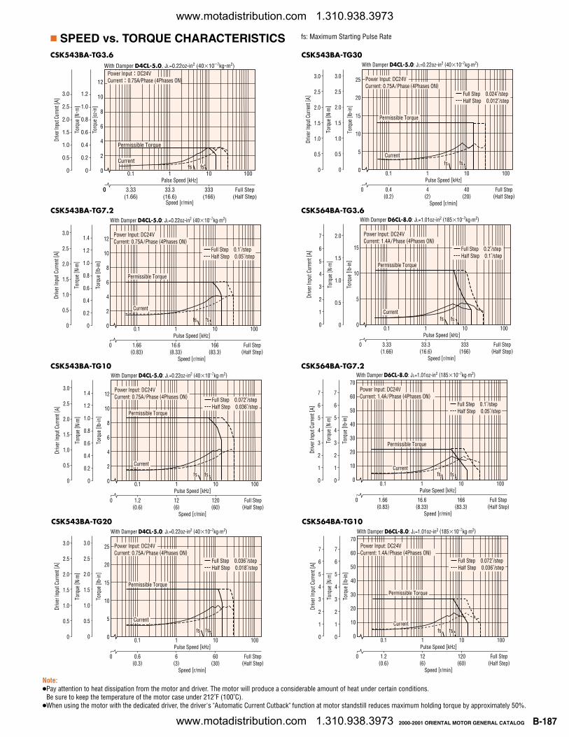
fs: Maximum Starting Pulse Rate SPEED vs. TORQUE CHARACTERISTICS
0.1 1 10 100
12
10
8
6
4
2
0
1.2
1.0
0.8
0.6
0.4
0.2
0
3.0
2.5
2.0
1.5
1.0
0.5
0
Drive
r Inp
ut C
urre
nt [A
]
Torq
ue [o
z-in]
Torq
ue [ N
m]
With Damper D4CL-5.0 JL=0.22oz-in2 (4010 7kg m2)
Palse Speed [kHz]
Speed [r/min]
3.33(1.66)
0 33.3(16.6)
333(166)
Full Step(Half Step)
0
Permissible Torque
Currentfs
Power Input DC24VCurrent 0.75A/Phase (4Phases ON)
fs
0.1 1 10 100
Torq
ue [ l
b-in
]
12
10
8
6
4
2
0
Pulse Speed [kHz]
Torq
ue [ N
·m]
3.0
2.5
2.0
1.5
1.0
0.5
0
Drive
r Inp
ut C
urre
nt [ A
]
With Damper D4CL-5.0: JL=0.22oz-in2 (4010–7kg·m2)
Speed [r/min]
1.66(0.83)
0 16.6(8.33)
166(83.3)
Full Step(Half Step)
Current
Power Input: DC24VCurrent: 0.75A /Phase (4Phases ON)
Full Step 0.1˚/stepHalf Step 0.05˚/step
fsfs
1.4
1.2
1.0
0.8
0.6
0.4
0.2
0
Permissible Torque
0.1 1 10 100
Torq
ue [ l
b-in
]
12
10
8
6
4
2
0
Pulse Speed [kHz]
Torq
ue [ N
·m]
3.0
2.5
2.0
1.5
1.0
0.5
0
Drive
r Inp
ut C
urre
nt [ A
]
With Damper D4CL-5.0: JL=0.22oz-in2 (4010–7kg·m2)
Speed [r/min]
1.2(0.6)
0 12(6)
120(60)
Full Step(Half Step)
Current
Power Input: DC24VCurrent: 0.75A /Phase (4Phases ON) Full Step 0.072˚/step
Half Step 0.036˚/step
fs
1.4
1.2
1.0
0.8
0.6
0.4
0.2
0
Permissible Torque
fs
0.1 1 10 100
Torq
ue [ l
b-in
]
25
20
15
10
5
0
Pulse Speed [kHz]
Torq
ue [ N
·m]
3.0
2.5
2.0
1.5
1.0
0.5
0
Drive
r Inp
ut C
urre
nt [ A
]
With Damper D4CL-5.0: JL=0.22oz-in2 (4010–7kg·m2)
Speed [r/min]
0.6(0.3)
0 6(3)
60(30)
Full Step(Half Step)
Current
Power Input: DC24VCurrent: 0.75A /Phase (4Phases ON)
Full Step 0.036˚/stepHalf Step 0.018˚/step
fs
3.0
2.5
2.0
1.5
1.0
0.5
0
Permissible Torque
fs
0.1 1 10 100
Torq
ue [ l
b-in
]
25
20
15
10
5
0
Pulse Speed [kHz]
Torq
ue [ N
·m]
3.0
2.5
2.0
1.5
1.0
0.5
0
Drive
r Inp
ut C
urre
nt [ A
]
With Damper D4CL-5.0: JL=0.22oz-in2 (4010–7kg·m2)
Speed [r/min]
0.4(0.2)
0 4(2)
40(20)
Full Step(Half Step)
Current
Power Input: DC24VCurrent: 0.75A /Phase (4Phases ON)
Full Step 0.024˚/stepHalf Step 0.012˚/step
fs
3.0
2.5
2.0
1.5
1.0
0.5
0
Permissible Torque
fs
0.1 1 10 100
Torq
ue [ l
b-in
]
15
10
5
0
Pulse Speed [kHz]To
rque
[ N·m
]
7
6
5
4
3
2
1
0
Drive
r Inp
ut C
urre
nt [ A
]
With Damper D6CL-8.0: JL=1.01oz-in2 (18510–7kg·m2)
Speed [r/min]
3.33(1.66)
0 33.3(16.6)
333(166)
Full Step(Half Step)
Current
Power Input: DC24VCurrent: 1.4A /Phase (4Phases ON)
Full Step 0.2˚/stepHalf Step 0.1˚/step
fs
2.0
1.5
1.0
0.5
0
Permissible Torque
fs
0.1 1 10 100
Torq
ue [ l
b-in
]
70
60
50
40
30
20
10
0
Pulse Speed [kHz]
Torq
ue [ N
·m]
7
6
5
4
3
2
1
0
Drive
r Inp
ut C
urre
nt [ A
]
With Damper D6CL-8.0: JL=1.01oz-in2 (18510–7kg·m2)
Speed [r/min]
1.66(0.83)
0 16.6(8.33)
166(83.3)
Full Step(Half Step)
Current
Power Input: DC24VCurrent: 1.4A /Phase (4Phases ON)
Full Step 0.1˚/stepHalf Step 0.05˚/step
fs
Permissible Torque
7
6
5
4
3
2
1
0fs
0.1 1 10 100
Torq
ue [ l
b-in
]
70
60
50
40
30
20
10
0
Pulse Speed [kHz]
Torq
ue [ N
·m]
7
6
5
4
3
2
1
0
Drive
r Inp
ut C
urre
nt [ A
]
With Damper D6CL-8.0: JL=1.01oz-in2 (18510–7kg·m2)
Speed [r/min]
1.2(0.6)
0 12(6)
120(60)
Full Step(Half Step)
Current
Power Input: DC24VCurrent: 1.4A /Phase (4Phases ON)
Full Step 0.072˚/stepHalf Step 0.036˚/step
fs
7
6
5
4
3
2
1
0fs
Permissible Torque
CSK543BA-TG10
CSK543BA-TG20
CSK543BA-TG3.6
CSK564BA-TG7.2
CSK564BA-TG10
CSK543BA-TG30
Note: Pay attention to heat dissipation from the motor and driver. The motor will produce a considerable amount of heat under certain conditions.
Be sure to keep the temperature of the motor case under 212˚F (100˚C).When using the motor with the dedicated driver, the driver's "Automatic Current Cutback" function at motor standstill reduces maximum holding torque by approximately 50%.
CSK564BA-TG3.6CSK543BA-TG7.2
www.motadistribution.com 1.310.938.3973
www.motadistribution.com 1.310.938.3973
B-188 2000-2001 ORIENTAL MOTOR GENERAL CATALOG
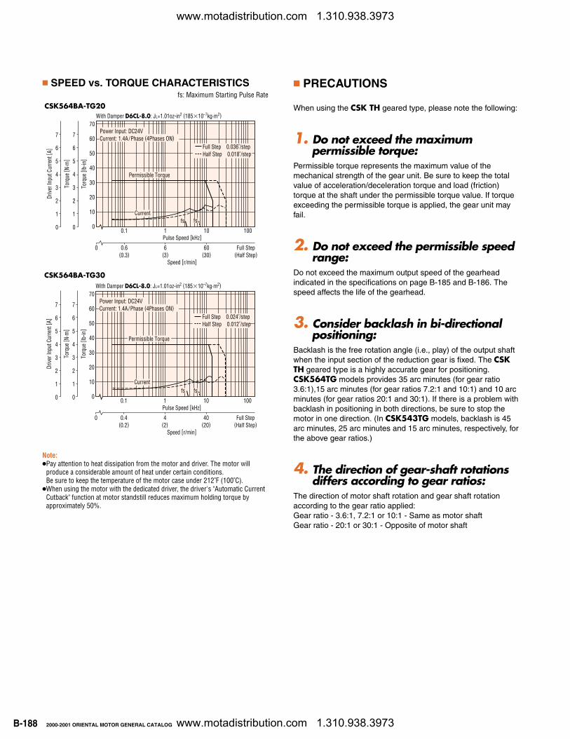
CSK564BA-TG30
PRECAUTIONS
When using the CSK TH geared type, please note the following:
1. Do not exceed the maximumpermissible torque:
Permissible torque represents the maximum value of themechanical strength of the gear unit. Be sure to keep the totalvalue of acceleration/deceleration torque and load (friction)torque at the shaft under the permissible torque value. If torqueexceeding the permissible torque is applied, the gear unit mayfail.
2. Do not exceed the permissible speedrange:
Do not exceed the maximum output speed of the gearheadindicated in the specifications on page B-185 and B-186. Thespeed affects the life of the gearhead.
3. Consider backlash in bi-directionalpositioning:
Backlash is the free rotation angle (i.e., play) of the output shaftwhen the input section of the reduction gear is fixed. The CSKTH geared type is a highly accurate gear for positioning.CSK564TG models provides 35 arc minutes (for gear ratio3.6:1),15 arc minutes (for gear ratios 7.2:1 and 10:1) and 10 arcminutes (for gear ratios 20:1 and 30:1). If there is a problem withbacklash in positioning in both directions, be sure to stop themotor in one direction. (In CSK543TG models, backlash is 45arc minutes, 25 arc minutes and 15 arc minutes, respectively, forthe above gear ratios.)
4. The direction of gear-shaft rotationsdiffers according to gear ratios:
The direction of motor shaft rotation and gear shaft rotationaccording to the gear ratio applied:Gear ratio - 3.6:1, 7.2:1 or 10:1 - Same as motor shaftGear ratio - 20:1 or 30:1 - Opposite of motor shaft
SPEED vs. TORQUE CHARACTERISTICS
CSK564BA-TG20
0.1 1 10 100
Torq
ue [ l
b-in
]
70
60
50
40
30
20
10
0
Pulse Speed [kHz]
Torq
ue [ N
·m]
7
6
5
4
3
2
1
0
Drive
r Inp
ut C
urre
nt [ A
]
With Damper D6CL-8.0: JL=1.01oz-in2 (18510–7kg·m2)
Speed [r/min]
0.4(0.2)
0 4(2)
40(20)
Full Step(Half Step)
Current
Power Input: DC24VCurrent: 1.4A /Phase (4Phases ON)
Full Step 0.024˚/stepHalf Step 0.012˚/step
fs
Permissible Torque
7
6
5
4
3
2
1
0fs
0.1 1 10 100
Torq
ue [ l
b-in
]
70
60
50
40
30
20
10
0
Pulse Speed [kHz]
Torq
ue [ N
·m]
7
6
5
4
3
2
1
0
Drive
r Inp
ut C
urre
nt [ A
]
With Damper D6CL-8.0: JL=1.01oz-in2 (18510–7kg·m2)
Speed [r/min]
0.6(0.3)
0 6(3)
60(30)
Full Step(Half Step)
Current
Power Input: DC24VCurrent: 1.4A /Phase (4Phases ON)
Full Step 0.036˚/stepHalf Step 0.018˚/step
fs
Permissible Torque
7
6
5
4
3
2
1
0fs
Note: Pay attention to heat dissipation from the motor and driver. The motor will
produce a considerable amount of heat under certain conditions. Be sure to keep the temperature of the motor case under 212˚F (100˚C).
When using the motor with the dedicated driver, the driver's "Automatic CurrentCutback" function at motor standstill reduces maximum holding torque byapproximately 50%.
fs: Maximum Starting Pulse Rate
www.motadistribution.com 1.310.938.3973
www.motadistribution.com 1.310.938.3973
B-1892000-2001 ORIENTAL MOTOR GENERAL CATALOG
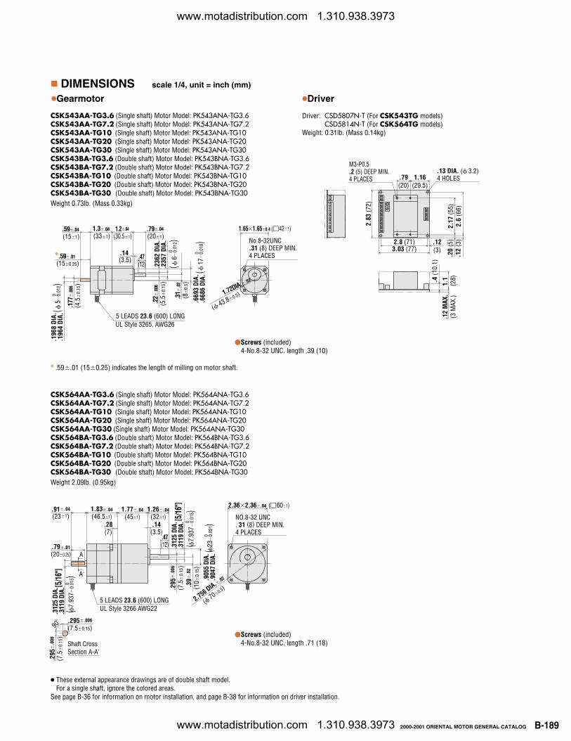
DIMENSIONS scale 1/4, unit = inch (mm)
Driver
See page B-36 for information on motor installation, and page B-38 for information on driver installation.
.12
MAX
.(3
MAX
.)
2.83
(72)
1.16(29.5)
.79(20)
.20
(5)
.12
(3)
.4 (1
0.1)
M3-P0.5 .2 (5) DEEP MIN. 4 PLACES
.13 DIA. ( 3.2)4 HOLES
2.6
(66)
2.17
(55)
.12(3)3.03 (77)
2.8 (71)
1.1
(28)
Driver: CSD5807N-T (For CSK543TG models)CSD5814N-T (For CSK564TG models)
Weight: 0.31lb. (Mass 0.14kg)
Gearmotor
CSK543AA-TG3.6 (Single shaft) Motor Model: PK543ANA-TG3.6CSK543AA-TG7.2 (Single shaft) Motor Model: PK543ANA-TG7.2CSK543AA-TG10 (Single shaft) Motor Model: PK543ANA-TG10CSK543AA-TG20 (Single shaft) Motor Model: PK543ANA-TG20CSK543AA-TG30 (Single shaft) Motor Model: PK543ANA-TG30CSK543BA-TG3.6 (Double shaft) Motor Model: PK543BNA-TG3.6CSK543BA-TG7.2 (Double shaft) Motor Model: PK543BNA-TG7.2CSK543BA-TG10 (Double shaft) Motor Model: PK543BNA-TG10CSK543BA-TG20 (Double shaft) Motor Model: PK543BNA-TG20CSK543BA-TG30 (Double shaft) Motor Model: PK543BNA-TG30
CSK564AA-TG3.6 (Single shaft) Motor Model: PK564ANA-TG3.6CSK564AA-TG7.2 (Single shaft) Motor Model: PK564ANA-TG7.2CSK564AA-TG10 (Single shaft) Motor Model: PK564ANA-TG10CSK564AA-TG20 (Single shaft) Motor Model: PK564ANA-TG20CSK564AA-TG30 (Single shaft) Motor Model: PK564ANA-TG30CSK564BA-TG3.6 (Double shaft) Motor Model: PK564BNA-TG3.6CSK564BA-TG7.2 (Double shaft) Motor Model: PK564BNA-TG7.2CSK564BA-TG10 (Double shaft) Motor Model: PK564BNA-TG10CSK564BA-TG20 (Double shaft) Motor Model: PK564BNA-TG20CSK564BA-TG30 (Double shaft) Motor Model: PK564BNA-TG30Weight 2.09lb. (0.95kg)
Weight 0.73lb. (Mass 0.33kg)
These external appearance drawings are of double shaft model.For a single shaft, ignore the colored areas.
UL Style 3265, AWG26
(151).59.04
(331)1.3.04
(30.51)1.2.04
(201).79.04
.14(3.5)(150.25)
.59.01
.196
8 DI
A..1
964
DIA.
0(
5
0.01
2)
(4.5
0.
15)
.177
.0
06
5 LEADS 23.6 (600) LONG
.47(12)
(5.5
0.
15)
.22
.006
.236
2 DI
A..2
357
DIA.
0(
6
0.01
2)(8
0.
5).3
1 .0
2
.669
3 DI
A..6
686
DIA.
0(
17
0.01
8) No.8-32UNC .31 (8) DEEP MIN.4 PLACES
1.651.650.4 (421)
1.72DIA..02
( 43.80.5)
Screws (included)4-No.8-32 UNC. length .71 (18)Shaft Cross
Section A-A'
A
A'
UL Style 3266 AWG225 LEADS 23.6 (600) LONG
.295.006
(7.50.15)
.295
.0
06
(7.5
0.
15)
.295
.0
06
(7.5
0.
15)
.39
.02
(10
0.15
)
90˚
2.362.36.04 (601)
NO.8-32 UNC. 31 (8) DEEP MIN.4 PLACES
.91.04
(231)1.83.04
(46.51)1.77.04
(451)1.26.04
(321).14
(3.5).28(7)
.47(12).79.01
(200.25)
.312
5 DI
A..3
119
DIA.
(7.9
37
0.01
5)0
.312
5 DI
A..3
119
DIA.
(7.9
37
0.01
5)0
(23
0.02
1)0
.905
5 DI
A..9
047
DIA.
2.756 DIA..02
( 700.5)
[5/1
6"]
[5/1
6"]
Screws (included)4-No.8-32 UNC. length .39 (10)
.59.01 (150.25) indicates the length of milling on motor shaft.
www.motadistribution.com 1.310.938.3973
www.motadistribution.com 1.310.938.3973
B-190 2000-2001 ORIENTAL MOTOR GENERAL CATALOG
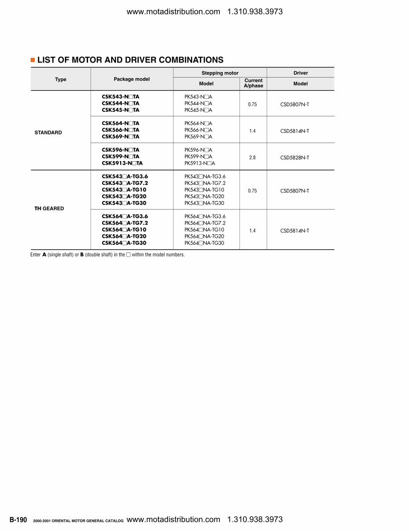
LIST OF MOTOR AND DRIVER COMBINATIONS
Type
STANDARD
TH GEARED
Package model
CSK543-NTACSK544-NTACSK545-NTA
CSK564-NTACSK566-NTACSK569-NTA
CSK596-NTACSK599-NTACSK5913-NTA
CSK543A-TG3.6CSK543A-TG7.2CSK543A-TG10CSK543A-TG20CSK543A-TG30
CSK564A-TG3.6CSK564A-TG7.2CSK564A-TG10CSK564A-TG20CSK564A-TG30
Model
PK543-NAPK544-NAPK545-NA
PK564-NAPK566-NAPK569-NA
PK596-NAPK599-NAPK5913-NA
PK543NA-TG3.6PK543NA-TG7.2PK543NA-TG10PK543NA-TG20PK543NA-TG30
PK564NA-TG3.6PK564NA-TG7.2PK564NA-TG10PK564NA-TG20PK564NA-TG30
0.75
1.4
2.8
0.75
1.4
Model
CSD5807N-T
CSD5814N-T
CSD5828N-T
CSD5807N-T
CSD5814N-T
Stepping motor Driver
Enter A (single shaft) or B (double shaft) in the within the model numbers.
CurrentA/phase
ST
EP
PIN
G M
OTO
RS
www.motadistribution.com 1.310.938.3973
www.motadistribution.com 1.310.938.3973
B-1912000-2001 ORIENTAL MOTOR GENERAL CATALOG
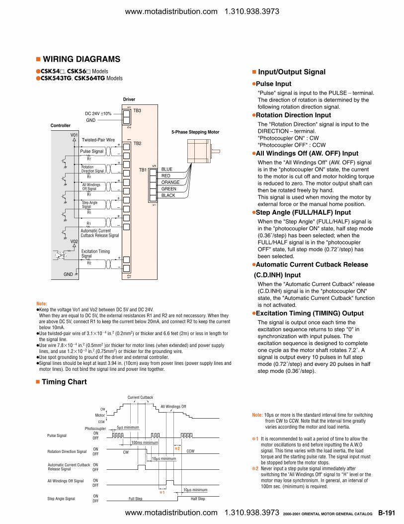
Note: 10µs or more is the standard interval time for switchingfrom CW to CCW. Note that the interval time greatlyvaries according the motor and load inertia.
1 It is recommended to wait a period of time to allow themotor oscillations to end before inputting the A.W.Osignal. This time varies with the load inertia, the loadtorque and the starting pulse rate. The signal input mustbe stopped before the motor stops.
2 Never input a step pulse signal immediately afterswitching the "All Windings Off" signal to “H” level or themotor may lose synchronism. In general, an interval of100m sec. (minimum) is required.
WIRING DIAGRAMS
Input/Output Signal
Rotation Direction Signal
All WindingsOff Signal
Step AngleSignal
Automatic Current Cutback Release Signal
5-Phase Stepping Motor
BLUEREDORANGEGREENBLACK
Controller
Driver
V01
Pulse Signal
TB2
DC 24V ±10%
GND
TB1
TB3
Twisted-Pair Wire
Excitation TimingSignal
GND
V02
5
21
121
1
+
–
+
–
+
–
+
–
+
–
+
–
R1
R1
R1
R1
R1
R2
Note:Keep the voltage Vo1 and Vo2 between DC 5V and DC 24V.
When they are equal to DC 5V, the external resistances R1 and R2 are not neccessory. When theyare above DC 5V, connect R1 to keep the current below 20mA, and connect R2 to keep the currentbelow 10mA.
Use twisted-pair wire of 3.1104 in.2 (0.2mm2) or thicker and 6.6 feet (2m) or less in length forthe signal line.
Use wire 7.8104 in.2 (0.5mm2 )or thicker for motor lines (when extended) and power supplylines, and use 1.2103 in.2 (0.75mm2) or thicker for the grounding wire.
Use spot grounding to ground of the driver and external controller. Signal lines should be kept at least 3.94 in. (10cm) away from power lines (power supply lines and
motor lines). Do not bind the signal line and power line together.
Timing Chart
10µs minimum
110µs minimum
CW CCW
Full Step Half Step
Pulse Signal
Rotation Direction Signal
Automatic Current CutbackRelease Signal
All Windings Off Signal
Step Angle Signal
Current Cutback
All Windings Off
Motor
CW
CCW
Photocoupler ONOFF
ONOFF
ONOFF
ONOFF
ONOFF
5µs minimum
100ms minimum2
Pulse Input"Pulse" signal is input to the PULSEterminal.The direction of rotation is determined by thefollowing rotation direction signal.
Rotation Direction InputThe "Rotation Direction" signal is input to theDIRECTIONterminal. "Photocoupler ON" : CW"Photocoupler OFF" : CCW
All Windings Off (AW. OFF) InputWhen the "All Windings Off" (AW. OFF) signalis in the "photocoupler ON" state, the currentto the motor is cut off and motor holding torqueis reduced to zero. The motor output shaft canthen be rotated freely by hand.This signal is used when moving the motor byexternal force or the manual home position.
Step Angle (FULL/HALF) InputWhen the "Step Angle" (FULL/HALF) signal isin the "photocoupler ON" state, half step mode(0.36˚/step) has been selected; when theFULL/HALF signal is in the "photocouplerOFF" state, full step mode (0.72˚/step) hasbeen selected.
Automatic Current Cutback Release
(C.D.INH) InputWhen the "Automatic Current Cutback" release(C.D.INH) signal is in the "photocoupler ON"state, the "Automatic Current Cutback" functionis not activated.
Excitation Timing (TIMING) OutputThe signal is output once each time theexcitation sequence returns to step "0" insynchronization with input pulses. Theexcitation sequence is designed to completeone cycle as the motor shaft rotates 7.2˚. Asignal is output every 10 pulses in full stepmode (0.72˚/step) and every 20 pulses in halfstep mode (0.36˚/step).
CSK54, CSK56 ModelsCSK543TG, CSK564TG Models
www.motadistribution.com 1.310.938.3973
www.motadistribution.com 1.310.938.3973
B-192 2000-2001 ORIENTAL MOTOR GENERAL CATALOG
Rotation Direction Input
All WindingsOff Input
Step AngleInput
Automatic Current Cutback Release Input
5-PhaseStepping
Motor
BLUEREDORANGEGREENBLACK
Controller
Driver
V01
Pulse Input
DC 24V ±10%
GND
Twisted-Pair Wire
Excitation TimingOutput
GND
V02
12
114
15
+
–
+
–
+
–
+
–
+
–
+
–
OverheatOutput
+
–
GND
R1
R1
R1
R1
R1
R2
R2
SIGNALPW
RM
OTOR
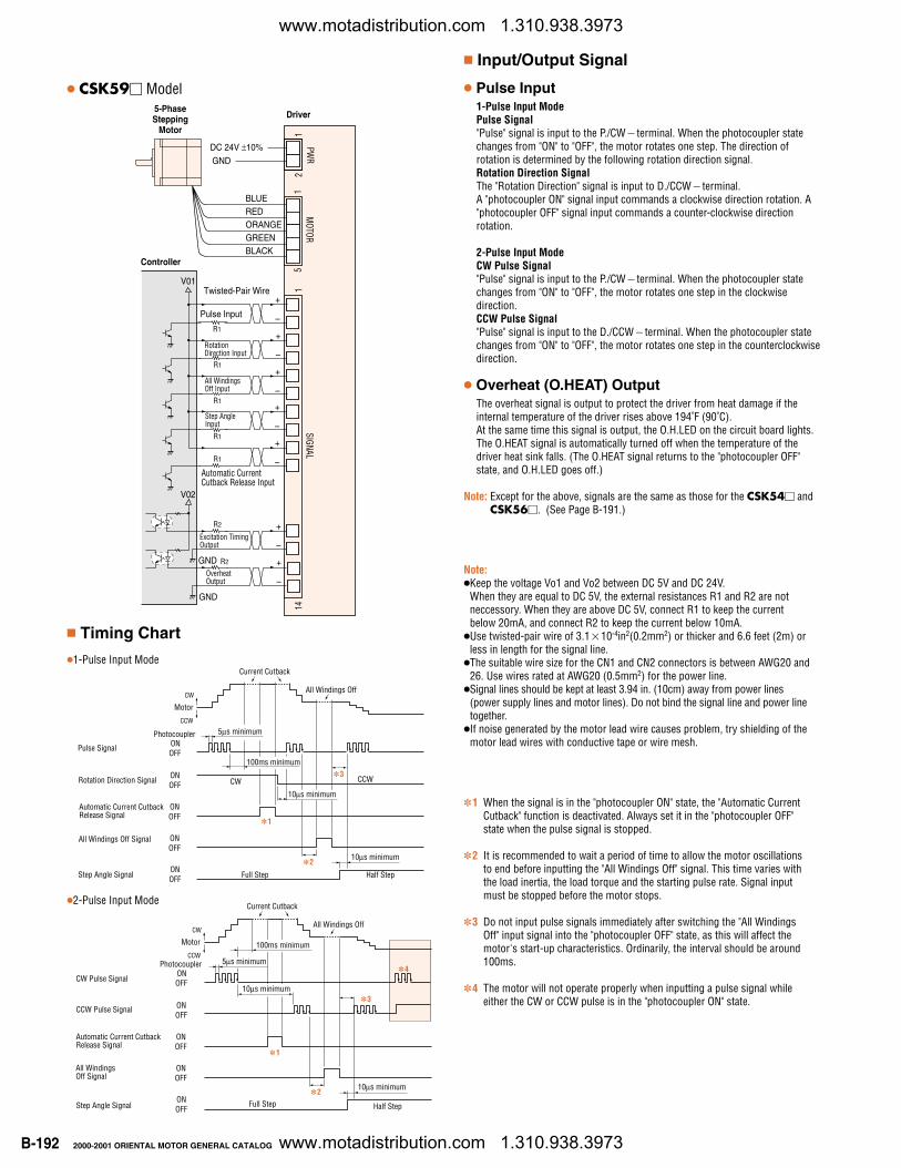
Note:Keep the voltage Vo1 and Vo2 between DC 5V and DC 24V.
When they are equal to DC 5V, the external resistances R1 and R2 are notneccessory. When they are above DC 5V, connect R1 to keep the currentbelow 20mA, and connect R2 to keep the current below 10mA.
Use twisted-pair wire of 3.110-4in2(0.2mm2) or thicker and 6.6 feet (2m) orless in length for the signal line.
The suitable wire size for the CN1 and CN2 connectors is between AWG20 and26. Use wires rated at AWG20 (0.5mm2) for the power line.
Signal lines should be kept at least 3.94 in. (10cm) away from power lines(power supply lines and motor lines). Do not bind the signal line and power linetogether.
If noise generated by the motor lead wire causes problem, try shielding of themotor lead wires with conductive tape or wire mesh.
Timing Chart
10µs minimum
210µs minimum
CW CCW
Full Step Half Step
Pulse Signal
Rotation Direction Signal
Automatic Current CutbackRelease Signal
All Windings Off Signal
Step Angle Signal
Current Cutback
All Windings Off
Motor
CW
CCW
Photocoupler ONOFF
ONOFF
ONOFF
ONOFF
ONOFF
5µs minimum
100ms minimum3
1
1 When the signal is in the "photocoupler ON" state, the "Automatic CurrentCutback" function is deactivated. Always set it in the "photocoupler OFF"state when the pulse signal is stopped.
2 It is recommended to wait a period of time to allow the motor oscillationsto end before inputting the "All Windings Off" signal. This time varies withthe load inertia, the load torque and the starting pulse rate. Signal inputmust be stopped before the motor stops.
3 Do not input pulse signals immediately after switching the "All WindingsOff" input signal into the "photocoupler OFF" state, as this will affect themotor's start-up characteristics. Ordinarily, the interval should be around100ms.
4 The motor will not operate properly when inputting a pulse signal whileeither the CW or CCW pulse is in the "photocoupler ON" state.
CSK59 Model
100ms minimum
10µs minimum
Full Step Half Step
Current Cutback
All Windings Off
Motor
CW
CCW
CW Pulse Signal
CCW Pulse Signal
Automatic Current CutbackRelease Signal
All WindingsOff Signal
Step Angle Signal
5µs minimum
10µs minimum
Photocoupler ONOFF
ONOFF
ONOFF
ONOFF
ONOFF
2
1
3
4
Input/Output Signal
Pulse Input1-Pulse Input ModePulse Signal"Pulse" signal is input to the P./CWterminal. When the photocoupler statechanges from "ON" to "OFF", the motor rotates one step. The direction ofrotation is determined by the following rotation direction signal.Rotation Direction SignalThe "Rotation Direction" signal is input to D./CCWterminal. A "photocoupler ON" signal input commands a clockwise direction rotation. A"photocoupler OFF" signal input commands a counter-clockwise directionrotation.
2-Pulse Input ModeCW Pulse Signal"Pulse" signal is input to the P./CWterminal. When the photocoupler statechanges from "ON" to "OFF", the motor rotates one step in the clockwisedirection.CCW Pulse Signal"Pulse" signal is input to the D./CCWterminal. When the photocoupler statechanges from "ON" to "OFF", the motor rotates one step in the counterclockwisedirection.
Overheat (O.HEAT) OutputThe overheat signal is output to protect the driver from heat damage if theinternal temperature of the driver rises above 194˚F (90˚C).At the same time this signal is output, the O.H.LED on the circuit board lights.The O.HEAT signal is automatically turned off when the temperature of thedriver heat sink falls. (The O.HEAT signal returns to the "photocoupler OFF"state, and O.H.LED goes off.)
Note: Except for the above, signals are the same as those for the CSK54 andCSK56. (See Page B-191.)
2-Pulse Input Mode
1-Pulse Input Mode
www.motadistribution.com 1.310.938.3973
www.motadistribution.com 1.310.938.3973
B-1932000-2001 ORIENTAL MOTOR GENERAL CATALOG
ADJUSTING THE OUTPUT CURRENT
1. Adjustment Method
Connecting an ammeter
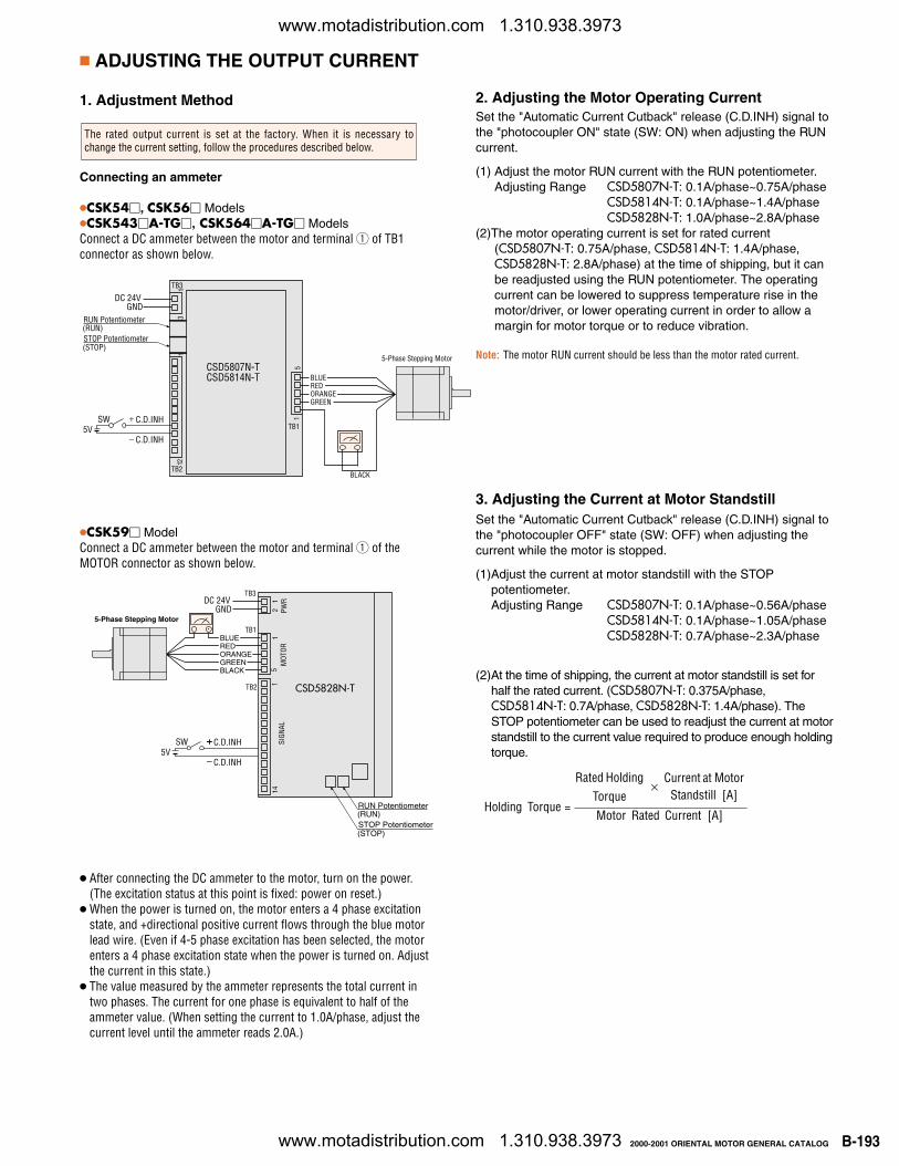
CSK54, CSK56 Models CSK543A-TG, CSK564A-TG Models Connect a DC ammeter between the motor and terminal 1 of TB1connector as shown below.
The rated output current is set at the factory. When it is necessary tochange the current setting, follow the procedures described below.
5VSW C.D.INH
C.D.INH
1
TB3
CSD5807N-TCSD5814N-T
RUN Potentiometer(RUN)STOP Potentiometer(STOP)
5-Phase Stepping Motor
5
BLUEREDORANGEGREEN
3
DC 24VGND
TB2
TB1
BLACK
12
1
1
CSK59 Model Connect a DC ammeter between the motor and terminal 1 of theMOTOR connector as shown below.
PWR
MOT
ORSI
GNAL
DC 24VGND
5VSW C.D.INH
C.D.INH
5-Phase Stepping Motor
CSD5828N-T
RUN Potentiometer(RUN)STOP Potentiometer(STOP)
BLUEREDORANGEGREENBLACK
1
TB3
5 2
TB2
TB1
141
1
After connecting the DC ammeter to the motor, turn on the power.(The excitation status at this point is fixed: power on reset.)
When the power is turned on, the motor enters a 4 phase excitationstate, and +directional positive current flows through the blue motorlead wire. (Even if 4-5 phase excitation has been selected, the motorenters a 4 phase excitation state when the power is turned on. Adjustthe current in this state.)
The value measured by the ammeter represents the total current intwo phases. The current for one phase is equivalent to half of theammeter value. (When setting the current to 1.0A/phase, adjust thecurrent level until the ammeter reads 2.0A.)
2. Adjusting the Motor Operating CurrentSet the "Automatic Current Cutback" release (C.D.INH) signal tothe "photocoupler ON" state (SW: ON) when adjusting the RUNcurrent.
(1) Adjust the motor RUN current with the RUN potentiometer. Adjusting Range CSD5807N-T: 0.1A/phase~0.75A/phase
CSD5814N-T: 0.1A/phase~1.4A/phaseCSD5828N-T: 1.0A/phase~2.8A/phase
(2)The motor operating current is set for rated current(CSD5807N-T: 0.75A/phase, CSD5814N-T: 1.4A/phase,CSD5828N-T: 2.8A/phase) at the time of shipping, but it canbe readjusted using the RUN potentiometer. The operatingcurrent can be lowered to suppress temperature rise in themotor/driver, or lower operating current in order to allow amargin for motor torque or to reduce vibration.
Note: The motor RUN current should be less than the motor rated current.
Holding Torque =
Rated HoldingTorque
×Current at Motor
Standstill [A]
Motor Rated Current [A]
3. Adjusting the Current at Motor Standstill Set the "Automatic Current Cutback" release (C.D.INH) signal tothe "photocoupler OFF" state (SW: OFF) when adjusting thecurrent while the motor is stopped.
(1)Adjust the current at motor standstill with the STOPpotentiometer.Adjusting Range CSD5807N-T: 0.1A/phase~0.56A/phase
CSD5814N-T: 0.1A/phase~1.05A/phaseCSD5828N-T: 0.7A/phase~2.3A/phase
(2)At the time of shipping, the current at motor standstill is set forhalf the rated current. (CSD5807N-T: 0.375A/phase,CSD5814N-T: 0.7A/phase, CSD5828N-T: 1.4A/phase). TheSTOP potentiometer can be used to readjust the current at motorstandstill to the current value required to produce enough holdingtorque.
www.motadistribution.com 1.310.938.3973
www.motadistribution.com 1.310.938.3973
B-194 2000-2001 ORIENTAL MOTOR GENERAL CATALOG
www.motadistribution.com 1.310.938.3973
www.motadistribution.com 1.310.938.3973