Embed Size (px)
Citation preview

Brian Cherry International Concrete Symposium - Paper No. 12 - Page 1
ORGANIC CORROSION INHIBITORS – NEW
BUILD AND EXISTING STRUCTURES
PERFORMANCE
J. Meyer
Cortec Corporation, St. Paul, Minnesota, US
SUMMARY: Corrosion of embedded steel is a leading cause of deterioration in reinforced concrete
structures. While concrete mix designs have become more durable, the possibility of cracking due to
shrinkage, movement, or other forces is a consideration when designing for long service life. In
addition, preserving integrity and extending the useful service life of existing structures is of
paramount importance. Migrating, organic corrosion inhibitors have been used for more than 30 years
in construction applications as an economical method of corrosion mitigation. This paper will give
details on the chemistry of organic corrosion inhibitors and their performance in new construction,
repair and specialty applications.
Keywords: Organic corrosion inhibitors, Migrating corrosion inhibitors, New construction, Repair,
Post tensioning, Service life.
1. INTRODUCTION
High performance mix designs have significantly improved the quality of today’s concrete. Unfortunately, cracking,
whether due to shrinkage, settlement or other forces, is a reality that is never completely eliminated no matter how good
your concrete is. The need for a corrosion inhibitor that can provide protection in the presence of minor cracks is very real.
In addition, with aging infrastructure, preserving the integrity of structures and extending useful service life is of paramount
importance. Topical corrosion inhibitor treatments must be capable of penetrating to the depth of embedded reinforcing
steel.
Migrating corrosion inhibitors meet these challenges in a cost effective manner. They are available in many different forms
for all types of construction – admixtures for new concrete; repair mortars and grouts; topical treatments; injectable
products; and many specialty formats.
Organic corrosion inhibitors (OCI) are amine based chemicals that possess appreciable saturated vapour pressure under
atmospheric conditions, thus allowing vapour transport of the inhibitive substance [1]. Concrete and other cementitious
materials have pore structures that allow for liquid and vapour diffusion of these chemicals throughout the substrate. When
organic inhibitors encounter embedded reinforcing, they have an attraction to it, adsorbing onto the metal surface forming a
protective molecular layer.
OCI are a mixed (anodic/cathodic) inhibitor system. The inhibition of the cathodic process is achieved by the incorporation
of one or more oxidising radicals in an organic molecule. Inhibitor molecules are hydrolysed in the electrolyte and then
adsorbed on the metal surface. The nitrogen of the amine group is capable of entering into a coordinate bond with metal
(including steel reinforcement) thus enhancing the adsorption process. Adsorption of amines and carboxylates increases
the resistivity of metal to corrosion. This molecular layer serves as a buffer to hold the pH at the interface in the basic
regime (above pH 9) [2].
Organic corrosion inhibitors migrate through the concrete depending on the OCI type and application method. OCI
admixtures are readily dispersed in the mixing process and can also migrate to reinforcement by diffusion as both a liquid
and a vapour. OCI topical treatments penetrate first as a liquid through capillary suction and then by diffusion [3]. OCI are
effective against chloride induced corrosion, as well as carbonation and other corrosive elements (H2S, SO2, etc.).
The first generation of OCI was based on amine alcohol technology. The latest generation is based on amine carboxylates
and was first introduced in the early 1990’s. The amine carboxylate technology includes by-products of corn – a renewable
resource.
Amine carboxylate based OCI can delay setting time of concrete 3-4 hours at 70°F (20°C). This delay is less pronounced
at warmer temperatures. Set delay is a desired side effect in warm weather as less retarder will need to be added to the
concrete mix when using OCI. Combining amine carboxylate based organic corrosion inhibitors with some set retarding

Brian Cherry International Concrete Symposium - Paper No. 12 - Page 2
materials (admixtures) may create increased setting times, but generally no other concrete properties are affected. In cases
where set delay is not desired, normal set (NS) versions of OCI have been developed, or non-chloride accelerators can be
used.
2. CHEMISTRY OF ORGANIC CORROSION INHIBITORS
Corrosion inhibitors are classified based upon the part of the corrosion cell that they affect. Organic corrosion inhibitors
are classified as mixed inhibitors, meaning they affect both anodic and cathodic portions of the corrosion cell. These
inhibitors adsorb onto metal, forming a protective molecular layer on steel surfaces. This film prevents corrosive elements
from further reacting with embedded reinforcement, and also reduces existing corrosion rates. Adsorption of the inhibitor
takes place via its polar functional group anchored to the metal while the non-polar or hydrophobic chain is oriented
perpendicularly to the metal surface. The hydrophobic chains not only repel aqueous corrosive fluids, but interact with
each other to form aggregates thereby forming a tight film on the metal surface [2]. Figures 1 and 2 illustrate adsorption of
amine alcohol and amine carboxylate organic inhibitors respectively.
Figure 1. Illustration of Amine Alcohol Inhibitor, where
R1,2,3 is H or alkyl group, OH tail end group
Figure 2. Illustration of Amine Carboxylate Inhibitor,
where R1,2,3 is H or alkyl group, OH tail end group
Migrating corrosion inhibitors reach embedded reinforcement in several ways. First, the inhibitor is dispersed through the
concrete with adequate mixing. The transportation of OCI within concrete then occurs via infiltration through concrete
pore capillary networks. Thirdly, due to their relatively high vapour pressures, OCI move via diffusion in a gaseous state
through the pore network and minor cracks. Finally, when the molecules come into contact with embedded metals, they
have a specific attraction (as described above) to it. This process is illustrated in Figures 3, 4, and 5.
The molecules move randomly from areas of high concentration to areas of low concentration until equilibrium is reached
(Fick’s 2nd
Law of Diffusion). Because of the final adsorption of OCI on embedded metal, the concentration gradient
drives OCI to move towards the metal. X-Ray Photoelectron Spectroscopy (XPS) analysis has demonstrated the nitrogen
rich layer (from amine moiety in OCI molecules) formed on rebar surfaces embedded in concrete that received a topical
treatment of OCI. This protective, monomolecular layer also reduces the corrosion rate [4,5].
Figure 3. Liquid OCI infiltration through concrete
capillary network
Figure 4. Vapour phase diffusion through concrete pores
and minor cracks
Figure 5. OCI Migrating Mechanisms – After liquid and vapour diffusion, showing final adsorption on metal
to form a protective layer
N ..
R1 R3
O
H
R2
N R1 R3
R2 O H
C O
R4
..

Brian Cherry International Concrete Symposium - Paper No. 12 - Page 3
Amine alcohols differ from amine carboxylates in their tail end group. As can be seen in Figures 1 and 2 above, the amine
alcohols contain an OH terminal group at the tail end, whereas amine carboxylates have no such hydrophilic terminal
group. The exposed OH group on amine alcohols makes it available to interact with water based electrolyte near the rebar.
This means that the amine alcohol film could more easily desorb from the metal surface compared to the amine carboxylate
film, and allow corrosive species (such as chlorides) to attack the metal. As a result the amine carboxylate based OCI by
nature have a more tenacious bond to the metal surface [2].
The strength of the bond between the OCI molecule and the rebar is what delays the onset of corrosion and reduces
corrosion rates compared to a control once initiated. With amine alcohols, we typically see a slight extension in time to
corrosion initiation, and corrosion currents cut in half compared to a control following corrosion initiation. With amine
carboxylates, we typically see a double to tripling in time to corrosion initiation, and once corrosion starts, rates are reduced
by 5-15 times compared to a control [6].
Another small effect amine carboxylates have is that as they migrate through the concrete, some of them will react with
calcium hydroxide to form calcium carboxylate/Ca(COO)2, an insoluble salt, which effectively blocks some of the pores,
making future ingress of chlorides and other contaminants more tortuous [7].
There are many test methods used to assess the efficacy of migrating corrosion inhibitors in concrete. It is important to
note that these tests are described by category – corrosion protection, migrating ability, film forming ability, and
compatibility with other materials.
2.1 Assessment of Corrosion Protection
The most widely used test method for evaluating concrete corrosion inhibiting admixtures is ASTM C1582 / C1582M –
Standard Specification for Admixtures to Inhibit Chloride-Induced Corrosion of Reinforcing Steel in Concrete [8]. This
standard consists of two components. The first is an evaluation of how the corrosion inhibitor affects concrete properties
such as setting time, air entrainment, compressive and flexural strengths, freeze thaw resistance, and length change.
The second component involves corrosion testing according to ASTM G109 – Standard Test Method for Determining
Effects of Chemical Admixtures on Corrosion of Embedded Steel Reinforcement in Concrete Exposed to Chloride
Environments [9] or ASTM G180 – 13, Standard Test Method for Corrosion Inhibiting Admixtures for Steel in Concrete by
Polarization Resistance in Cementitious Slurries [10].
ASTM G109 test samples can be seen in Figures 6 and 7 below. The test consists of casting concrete blocks containing a
triangular arrangement of rebar embedded within them – one bar on top and two on the bottom. These samples are then
exposed to cyclic wetting and drying cycles with salt water, and the macrocell current between the top bar and bottom two
bars is monitored and recorded every 4 weeks (4 weeks = one cycle). The testing stops once the total integrated macrocell
current reaches 150 Coulombs.
Figure 6. Example of ASTM G109 Test Blocks Figure 7. Example of ASTM G109 Test
Blocks
The ASTM G180 – 13 [10] test setup can be seen in Figure 8. This test method provides a means for assessing corrosion-
inhibiting concrete admixtures in a filtered cementitious liquid. Compared with a testing period of up to a few years
required by ASTM G 109, this test method provides results within a few days. In this test, the polarization resistance of a
steel sample is measured by applying a current through the test solution while varying the voltage. According to ASTM
C1582, an admixture is behaving as a corrosion inhibitor when using the G180 Test Method (using 0.5 M NaCl with four
control and four test specimens) if the mean 1/Rp value is less than or equal to 1/8 the control average. Poor performance in
G180 requires additional testing to determine if the admixture improves corrosion resistance.

Brian Cherry International Concrete Symposium - Paper No. 12 - Page 4
Figure 8. ASTM G180 Test Set-Up Figure 9. EIS Test Set-Up
Electrochemical Impedance Spectroscopy (EIS), Figure 9, is a powerful, rapid and accurate non-destructive method for the
evaluation of a wide range of materials including coatings, anodised films and organic corrosion inhibitors on metal
surfaces [11]. During EIS experiments, a small amplitude AC signal is applied to the metal system being studied. Data from
EIS can provide detailed information on corrosion rate, electrochemical mechanisms, reaction kinetics, and detection of
localised corrosion in a system.
In addition to the above standard tests, ASTM G109 is frequently modified to make it more aggressive so results can be
seen faster. These tests are generally referred to as a Modified ASTM G109 or a cracked beam test. In a cracked beam test,
test samples are created in the same manner as the ASTM G109 standard shown above, but the beams are cracked in a
controlled way (saw cut and application of flexural stress) prior to salt water cycling to make the test more aggressive.
Other modifications include changing the NaCl (salt) concentration (increasing from 3.5% to 6%) as well as the cycle times
(adjusting from 4 weeks down to as little as 1 week cycles). Another variation on ASTM G109 is permanent immersion of
concrete beams in salt water instead of using ponding cycles.
The most recent test for evaluating organic corrosion inhibitors in repair applications is the U.S. Bureau of Reclamation M-
82 - Standard Protocol to Evaluate the Performance of Corrosion Mitigation Technologies in Concrete Repairs (USBR M-
82) [12]. USBR M-82, Figure 10, is the outcome of a pilot program which was conducted by the Bureau of Reclamation
under a cooperative agreement with the Strategic Development Council. The contract to develop the protocol was awarded
to Tourney Consulting Group in the US and was funded by the US Bureau of Reclamation with funds from the American
Concrete Institute (ACI) Foundation. The protocol covers two methods for measuring and differentiating the performance
of reinforcing steel corrosion mitigating techniques for concrete repairs caused by damage due to chloride ingress. This
protocol doesn't differentiate between active and passive corrosion, but it has all of the positive aspects of impedance
testing (described in EIS above) but on a larger scale which is more representative of slabs in the field [13].
M-82 involves the production of 101.6cm long by 101.6 cm wide x 13.97cm thick (all dimensions +/- 1.27cm) concrete
slabs with discrete steel reinforcing bars near the top of the slab (~2.54cm from surface) and welded-wire reinforcing
(WWR) near the bottom of the slab (~2.54cm from bottom), Figure 10. The steel bars are connected to the WWR through
1 ohm (Ω) resistors through switches in a junction box attached to the side of the slab. Concrete slabs are cyclically ponded
with a 5% by mass sodium chloride (NaCl) solution for two weeks and then the solution is removed for two weeks (one test
cycle). Macrocell current between each bar and the WWR is determined by measuring the voltage drop across the resistor
within 24 hours of the start and immediately prior to the end of each ponding cycle. The positive macrocell currents
(reinforcing steel bar is corroding) are integrated over time to have total macrocell corrosion for each bar. The total for all
of the bars is also determined. The switches in the junction box are set so that all the bars and the WWR can be electrically
connected through the resistors. For potential mapping the bars are connected.

Brian Cherry International Concrete Symposium - Paper No. 12 - Page 5
Figure 10. Photo and Bar Layout Diagram of M-82 Test blocks
2.2 Assessment of Migrating Ability
Migration of OCI materials into concrete can be evaluated using UV Spectroscopy [14]. This method allows us to detect
OCI presence at various depths of concrete by analysing sliced core samples. OCIs are visible in the UV range. By
extracting powdered concrete in deionised water, and measuring the extract using UV spectroscopy, the presence of OCI in
concrete can be detected. This is done by comparing the absorbance values from treated concrete against the absorbance
values of untreated concrete at specific wavelengths. While initial results are only qualitative, if a calibration curve is
created with known doses of OCI, the actual concentration can be more accurately determined.
2.3 Assessment of Film Forming Ability
The film forming ability of OCIs can be measured using Scanning Electron Microscopy (SEM) and X-ray Photoelectron
Spectroscopy (XPS). SEM is microscopy that produces images of a sample by scanning it with a focused beam of
electrons. The electrons interact with atoms in the sample, producing various signals that can be detected. SEM coupled
with EDAX Energy Dispersive Spectroscopy (EDS) Detector can provide enriched information about the sample's surface
composition and topology. The presence of OCI, or the lack of it, on metal surfaces can thus be detected [15].
XPS is a spectroscopic technique in which a beam of x-rays is focused onto the surface of a material and as the beam
bounces off the surface it is received by an electron collection device. The data received is then analysed to determine the
elemental composition of the material which reflected the x-ray beam. A diagram showing how XPS works can be seen in
Figure 11.
Figure 11. Diagram of XPS Process
In terms of organic, migrating corrosion inhibitors XPS detection can be used to analyse a sample of rebar to determine if
there is inhibitor on the surface. Both amine alcohols and amine carboxylates are nitrogen containing compounds which is
not found in abundance in the concrete matrix. Therefore, nitrogen levels (relative concentration when comparing two
plots, i.e. control vs. treated) recorded on the XPS spectrogram can be used to determine if corrosion inhibitor has migrated
to the depth of the rebar. XPS also has the capability to look at the depth at which an element is from the surface of the

Brian Cherry International Concrete Symposium - Paper No. 12 - Page 6
steel so the spectrogram can be used to determine depth at which the corrosion inhibitor adsorbed into the rebar in
comparison to other elements like chloride.
3. NEW CONSTRUCTION APPLICATIONS
In new construction, organic corrosion inhibitors are incorporated into concrete as an admixture, either by adding to the
mix water at a ready mix plant, or by adding on the jobsite to the ready mix truck prior to pouring. Their dosage rate is
independent of the expected chloride levels. The recommended dosage rate is a sufficient concentration of inhibitor to
form a monomolecular film on embedded metals and is independent of chloride concentrations. Unlike anodic inhibitors
such as calcium nitrite, OCI do not have a “dangerous” concentration level – situations where a lower than required dosage
rate relative to chloride content concentration would promote pitting corrosion [16].
The latest generation of OCI admixtures, based on amine carboxylates, are certified to meet NSF/ANSI 61 – 2016 Drinking
Water System Components -Health Effects requirements, meaning they are safe for use at their recommended dosage rates
in structures containing potable water [17]. These corrosion inhibitors also contain renewable resources as raw materials –
one of the corrosion inhibiting materials in the amine carboxylate admixtures is derived from corn. They have been tested
to ASTM C1582 / C1582M – Standard Specification for Admixtures to Inhibit Chloride-Induced Corrosion of Reinforcing
Steel in Concrete [18] and pass the requirements for both physical property effects on concrete as well as for corrosion
inhibition capability.
3.1 Randolph Avenue Bridge
One of the oldest applications of OCI admixtures was a bridge deck overlay done in 1986 on the Randolph Avenue Bridge
which spans Interstate 35E in St. Paul, MN. The bridge is located in an area where winters are severe and de-icing salts are
heavily used to combat icy road conditions. Originally built in 1963, the deck underwent repair in 1986 to mitigate
chloride induced corrosion of the reinforcing steel and spalling that was occurring. Repair involved removing deteriorated
concrete, and milling to within 13 mm of embedded reinforcement. Deeper areas of unsound or damaged concrete were
also removed, resulting in varying depths of extraction according to the degree of deterioration. The deck was then
replaced with a low slump, dense concrete (LSDC) overlay. Depth of the overlay varied from 58 to 107 mm, with the top
layer of reinforcing steel located at 76 mm depth. Mix design for the overlay is shown in Table 1. An amine alcohol based
OCI admixture was added to the overlay for the two westbound traffic lanes at a rate of 0.6 l/m3. The two eastbound traffic
lanes used the same mix design without the corrosion inhibitor, to act as a control. The deck of the bridge slants towards
the northeast for water runoff. Due to the exposure conditions, the westbound lanes were experiencing more damage than
the eastbound lanes, resulting in a slightly thicker mean depth (8 mm thicker) of the overlay on the westbound lanes vs. the
eastbound lanes (according to measurements taken in 1991) [19].
Table 1. Mix Design of LSDC Overlay – Randolph Avenue Bridge
Component Control (kg/m3) –
Eastbound Lanes
Treated (kg/m3) –
Westbound Lanes
Type I Cement 496 496
Water 160 160
W/C Ratio 0.32 0.32
Coarse Aggregate 821.69 821.69
Fine Aggregate 815.16 815.16
Water-Reducing Admixture 0.148 0.148
Air-Entraining Agent 0.043 0.043
Organic Corrosion Inhibitor -- 0.564
The project was sponsored by the Minnesota Department of Transportation (MNDOT) and a part of a corrosion study with
the Federal Highway Administration (FHWA) from 1986-1990. In June 1991 and August 1992, researchers from Virginia
Tech conducted corrosion assessments, including visual inspections, chloride content as a function of depth, electrode
(half-cell) potentials, and estimates of corrosion current densities (icorr), using a 3LP (“3 electrode, linear polarisation”)
meter.
In November 2000, June 2007 and July 2011, local technicians returned to the bridge and took new measurements.
Measurements included linear polarisation resistance (using Gecor 6 [20,21] and GalvaPulse [22,23] devices), as well as
alkalinity, half-cell potentials and chloride content (profile) testing.

Brian Cherry International Concrete Symposium - Paper No. 12 - Page 7
Based on the service life prediction model, LIFE-365 [24], the chloride threshold of concrete is 0.05% by weight of the
concrete. This converts to 0.4% by weight of cement, or to 1.98 kg/m3 (assuming a concrete bulk density of 3960 kg/m
3).
Chloride contents shown in Table 2 indicate that the chloride levels in the control side were slightly higher than the treated
side and that they have continued to rise at the depth of the steel over time.
Table 2. Average Chloride Levels – Randolph Avenue Bridge
Year Treated (kg/m3) Control (kg/m
3)
0-2.54 cm 2.54-5.08 cm 5.08-7.62 cm 0-2.54 cm 2.54-5.08 cm 5.08-7.62 cm
1991 2.08 0 0.415 4.57 1.48 1.13
1992 3.86 0.65 1.13 5.64 2.08 1.48
2000 6.94 0.95 0.77 10.2 3.67 1.42
2007 6.94 0.59 1.54 11.87 4.39 1.36
2011 7.30 2.91 1.07 8.72 3.92 2.08
Corrosion current readings, Figure 11, have increased on both sides of the bridge over time. Readings taken in July of 2011
showed that the control side had entered into active corrosion levels (corrosion rate readings above 0.5µA/cm2). All three
sections tested indicated readings in the active corrosion range with the highest rate of corrosion recorded in the centre
section of the control side, with an average reading of 1.27 µA/cm2. In comparison, all three sections of the control side
had readings in the passive range (corrosion rate readings less than 0.5µA/cm2), with the highest being the centre section
with an average reading of 0.42µA/cm2, indicating the treated side had roughly 67% lower rates than the untreated areas.
Figure 12. Randolph Avenue Bridge Average Corrosion Rates
Half-cell (electrode) potential readings can be seen in Figure 13. This figure shows that the electrode potential is more
negative on the control side and has been for 20 years suggesting increased corrosion activity. This data along with the rest
of the supporting information indicate that the level of corrosion on the treated side of the bridge is lower than the control
areas.

Brian Cherry International Concrete Symposium - Paper No. 12 - Page 8
Figure 13. Randolph Avenue Bridge Average Corrosion Rates
3.2 Princess Tower Building, Dubai, UAE
The Princess Tower is a 101 story, 413.4 m [25] tall, residential-only skyscraper located in the Marina district of Dubai,
UAE. When constructed, Princess tower was the tallest residential building in the world, but lost its top ranking in 2015 to
432 Park Avenue in New York City. Princess Tower remains the second tallest building in Dubai after Burj Khalifa, and
the 20th tallest building in the world [26].
The building was completed and delivered by its developer, Tameer Holdings, in September 2012 and consists of 107
floors (6 basement levels, ground floor + 100 floors height above). It holds 763 residential units consisting of 1, 2, and 3
bedroom apartments, duplexes, and penthouses, together with 8 retail shops. It also houses 957 parking spaces.
In many areas of Dubai there is a high water table, as well as extremely high levels of chlorides and other contaminants in
the soils where superstructures are being built. The level of chlorides in the ground water in this area has been shown to
reach 90,000 mg/L in some cases. This aggressive environment leads to increased concern over the potential for corrosion
and the impact on service life expectations. Service life analysis using LIFE-365 [24] software was utilised by the design
engineers to see if the mix design proposed could meet the desired 100 year service life. Addition of an OCI admixture
increases chloride threshold and slows corrosion rates once initiated. The chloride threshold increases from 0.05%
(control) to 0.18% (OCI), and the propagation time increases from 6 years (control) to 30 years (OCI) to represent the
reduced corrosion rate compared to a control. Table 3 shows the estimated construction cost of the building, the cost to add
an amine carboxylate based organic corrosion inhibitor to the substructure of the building, as well as the expected service
life of the substructure with and without the inhibitor addition. In this scenario, service life is defined as the time to first
repair for the structure.
Table 3. Service Life & Cost Estimates – Princess Tower
Item Cost (USD)
Construction Cost $188,000,000
Additional Cost OCI in substructure $136,000 (0.07% of total cost)
LIFE-365 Service Life no OCI 48 Years
LIFE-365 Service Life with OCI 103 Years
Further analysis was done by the supplier to estimate the return on investment (ROI) that could be gained by delaying
costly repairs/maintenance on the substructure. Given that the building contains 763 rental units, calculation estimates

Brian Cherry International Concrete Symposium - Paper No. 12 - Page 9
were done to consider anticipated revenue, minus building management, licensing, insurance, maintenance, and other costs
over the design life of the structure. These calculations can be seen in Table 4.
Table 4. ROI Estimates (USD) – Princess Tower
Year 1 10 48 100
Revenue $28,066,757 $33,542,373 $71,186,938 $199,346,790
Building
Management $2,079,022 $2,712,653 $8,340,820 $38,792,200
Licensing &
Insurance $3,754,768 $4,106,535 $5,993,600 $10,055,396
Others $3,754,768 $4,106,535 $5,993,600 $10,055,396
Total Cost $9,588,559 $10,925,722 $20,328,019 $58,902,991
Net Profit $18,478,198 $22,616,651 $50,858,920 $140,443,799
Return on
Investment 9.8% 12.0% 27.1% 74.8%
Present
Value @ 3%
discount rate
$18,478,198 $16,828,912 $12,307,798 $7,307,690
ROI $18,478,198 $174,387,898 $724,175,783 $1,224,731,446
One can see that the ROI breaks even approximately 10.5 years into the life of the building. At 48 years, the property
would have generated an additional $536,175,783 in profit over the initial building cost. Extending the life to 100 years
with an OCI inhibitor, generates an additional $1,036,731,446 in profit – 93% more profit for an additional 0.07% in
construction costs.
3.3 Vachon Bridge, Montreal, QB, Canada
The Vachon Bridge is a structure that is north of Montreal that carries Highway 13 over the Mille- Îles River [27]. The
project was a study to determine the performance and factors affecting the effectiveness of corrosion inhibitors in bridge
deck repairs. Corrosion inhibiting systems studied consisted of concrete admixtures, epoxy coated reinforcement, and/or
concrete sealers/coatings. The consortium involved was formed by the National Research Council of Canada with other
interested groups including owners and manufacturers.
At the end of the ten year study, an inorganic admixture, calcium nitrite (CNI), dosed at 20 L/m3 was ranked as best
performing overall, followed by an organic corrosion inhibitor, dosed at 0.6 L/m3. It was noted that all systems had higher
corrosion rate readings in areas of the structure that experienced vertical shrinkage cracks shortly after construction. The
five year interim report presented results of field testing that included corrosion rate information. Where there was
cracking, the OCI admixture (Span F) had the lowest corrosion rate of all methods tested, while the CNI (Span H)
admixture performed worse than the control span (Span 21), Figure 14(Corrosion Rate of Reinforcement, Cracks) [28].
Brian Cherry International Concrete Symposium - Paper No. 12 - Page 10
Figure14. Field Performance Ranking of Corrosion Inhibiting Systems Used on Vachon Bridge. Span 21 is Control,
Span 12 is Epoxy Coated Reinforcing Steel, Span F is OCI Admixture, and Span H is Calcium Nitrite Admixture
4. REPAIR APPLICATIONS
Organic Corrosion inhibitors can also provide protection to existing concrete structures through topical coating or repair
mortar application. Products in this category generally come in the forms of A) Pure inhibitor solution to be applied on to
the concrete surface – the inhibitors will then be transported to embedded steel rebar via capillary infiltration and vapour
phase diffusion; B) Hydrophobic sealer with OCI component – this approach protects by reducing ingress of corrosive
species while simultaneously forming a barrier layer on the rebar surface though the action of the OCI molecules; and C)
OCI containing repair mortar that supplies the rebar with the migrating corrosion inhibitors. When comparing surface
treatments, generally the water based OCI solutions (Example A above, “pure inhibitor”) contain 2-3 times more inhibitor
than the water repellent versions with OCI added in (Example B above, “hydrophobic sealer + inhibitor”), .
Several OCI topical treatments are certified to meet NSF/ANSI 61 – 2016 Drinking Water System Components -Health
Effects [17] requirements, meaning they are safe for use at their recommended dosage rates in structures containing potable
water.
OCI topical treatments have also been tested to USBR M-82 [12], EIS [11], modified ASTM G109 [29], XPS and SEM
[15] to show their corrosion protection capabilities as well as their migrating capabilities.
USBR M-82 Protocol was run on three OCI topical treatments. Treatment A was a 20-25% OCI in water solution,
followed by a 40% silane water repellent; Treatment B was a 40% silane water repellent containing 2.5-10% OCI; and,
Treatment C was 100% silane water repellent containing 2.5-10% OCI. The testing was done according to Configuration A
of the slabs in the Protocol (used when the repair treatment is to be surface applied only), and the OCI repair treatments
were applied after 10,000 Coulombs of macrocell current had been reached. This variation of the test is used if the repair
method does not depend upon the amount of chloride present at the reinforcing bars, or protection at a higher initial
chloride content is to be demonstrated [30].
Table 5 shows chloride levels at time of repair and at the end of testing. All of the control slabs showed a statistically
significant (95% CL) increase in chloride levels from the time of repair to the end of testing. However, for the treated slabs
there was no a statistically significant change (less stringent 90% CL) in chloride levels from the time to repair to the end of
testing. The topical treatments used were expected to decrease the ingress of chloride, and that is evident in the data shown
in Table 5.

Brian Cherry International Concrete Symposium - Paper No. 12 - Page 11
Table 5. Average Chloride Values (ppm) Before Repair and At Test End (USBR M-82 Protocol Configuration A)
Control
Treatment A
(20-25% OCI in
water + 40%
Silane)
Treatment B
(40% Silane +
2.5-10% OCI)
Treatment C
(100% +
2.5-10% OCI)
Repair End Repair End Repair End Repair End
Average 2604 3520 2378 2620 2706 2600 2744 2540
SD 181 264 268 223 399 190 147 171
Sp 242
95% CL 230
90% CL 190
Table 6 shows the total crack length and average width following the USBR M-82 Protocol Configuration A testing.
Cracking is due to corrosion of the reinforcing steel. The 95% confidence limits in the table do not overlap, so there is a
statistically significant reduction in crack length and area for the treated slabs versus the control slabs.
Table 6. Crack Length and Area by Treatment (USBR M-82 Protocol Configuration A)
Length (mm) Area (mm2)
Average SD Average SD
Control 2315 311 284 78.55
Treatment A
(20-25% OCI in
water + 40%
Silane)
915 820 106.06 101.24
Treatment B
(40% Silane +
2.5-10% OCI)
689 341 75.10 44.496
Treatment C
(100% +
2.5-10% OCI)
465 527 51.92 61.63
Sp 539 74
95% CL 511 71
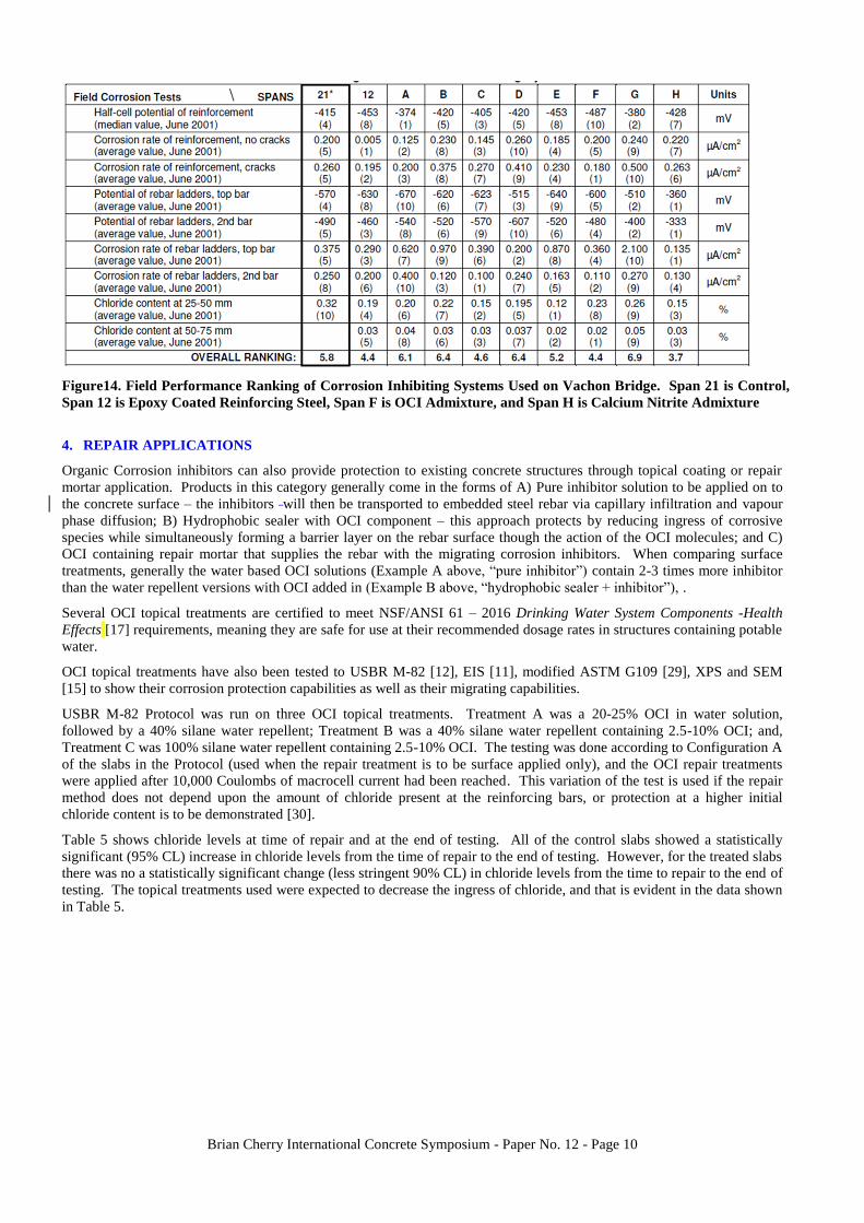
At the end of testing, slabs were excavated and bars visually inspected for corrosion damage. The galvanic corrosion
between the top bars and the wire mesh (macrocell current) is measured and integrated over time. Based on macrocell data,
the majority of the corrosion on embedded bars occurred before the OCI treatments were made to the slabs. Figure 15
shows the average integrated corrosion current (coulombs) after OCI repair treatments were applied.
Brian Cherry International Concrete Symposium - Paper No. 12 - Page 12
Figure 15. Average Integrated Current (After OCI Treatments) (USBR M-82 Protocol
Configuration A Test)
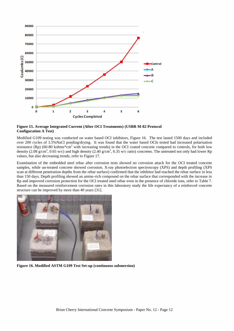
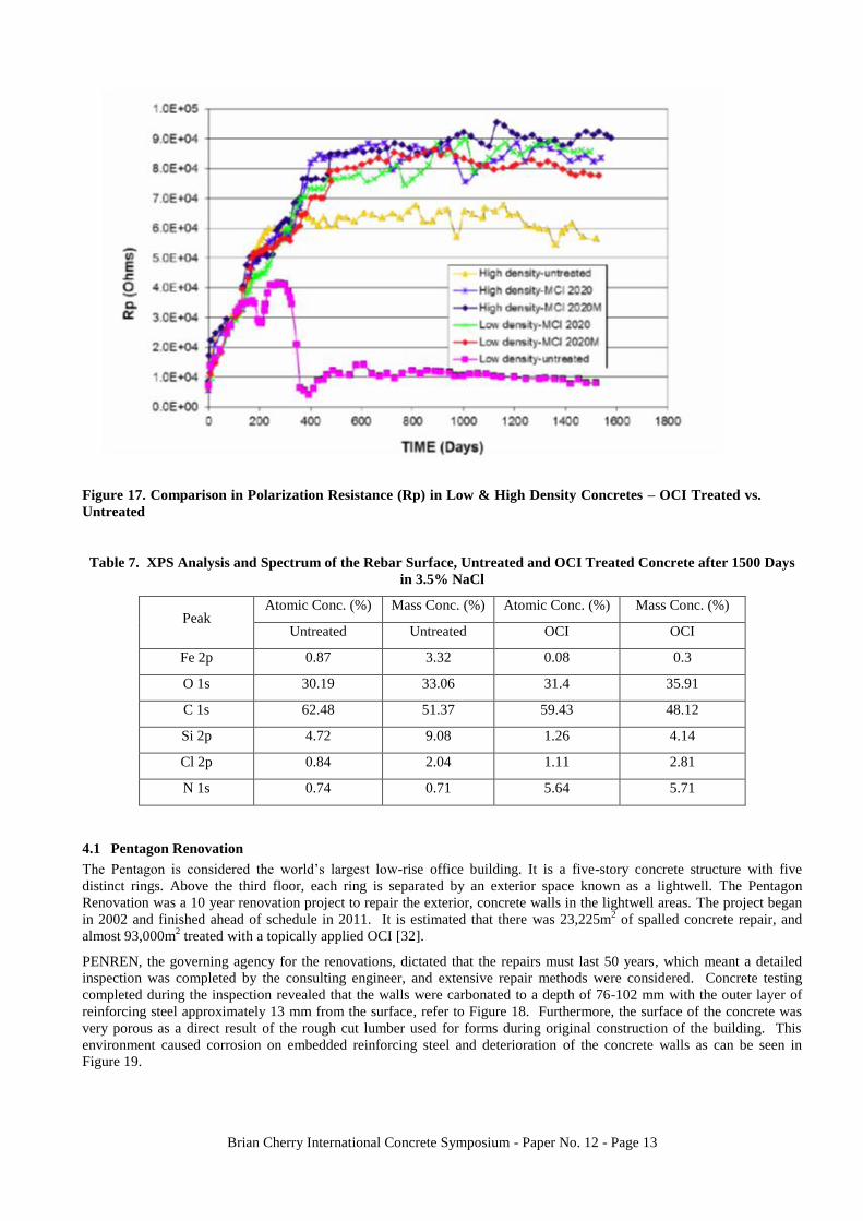
Modified G109 testing was conducted on water based OCI inhibitors, Figure 16. The test lasted 1500 days and included
over 200 cycles of 3.5%NaCl ponding/drying. It was found that the water based OCIs tested had increased polarisation
resistance (Rp) (60-80 kohms*cm2 with increasing trends) in the OCI coated concrete compared to controls, for both low
density (2.08 g/cm3, 0.65 w/c) and high density (2.40 g/cm
3, 0.35 w/c ratio) concretes. The untreated not only had lower Rp
values, but also decreasing trends, refer to Figure 17.
Examination of the embedded steel rebar after corrosion tests showed no corrosion attack for the OCI treated concrete
samples, while un-treated concrete showed corrosion. X-ray photoelectron spectroscopy (XPS) and depth profiling (XPS
scan at different penetration depths from the rebar surface) confirmed that the inhibitor had reached the rebar surface in less
than 150 days. Depth profiling showed an amine-rich compound on the rebar surface that corresponded with the increase in
Rp and improved corrosion protection for the OCI treated steel rebar even in the presence of chloride ions, refer to Table 7.
Based on the measured reinforcement corrosion rates in this laboratory study the life expectancy of a reinforced concrete
structure can be improved by more than 40 years [31].
Figure 16. Modified ASTM G109 Test Set-up (continuous submersion)
Brian Cherry International Concrete Symposium - Paper No. 12 - Page 13
Figure 17. Comparison in Polarization Resistance (Rp) in Low & High Density Concretes – OCI Treated vs.
Untreated
Table 7. XPS Analysis and Spectrum of the Rebar Surface, Untreated and OCI Treated Concrete after 1500 Days
in 3.5% NaCl
Peak Atomic Conc. (%) Mass Conc. (%) Atomic Conc. (%) Mass Conc. (%)
Untreated Untreated OCI OCI
Fe 2p 0.87 3.32 0.08 0.3
O 1s 30.19 33.06 31.4 35.91
C 1s 62.48 51.37 59.43 48.12
Si 2p 4.72 9.08 1.26 4.14
Cl 2p 0.84 2.04 1.11 2.81
N 1s 0.74 0.71 5.64 5.71
4.1 Pentagon Renovation
The Pentagon is considered the world’s largest low-rise office building. It is a five-story concrete structure with five
distinct rings. Above the third floor, each ring is separated by an exterior space known as a lightwell. The Pentagon
Renovation was a 10 year renovation project to repair the exterior, concrete walls in the lightwell areas. The project began
in 2002 and finished ahead of schedule in 2011. It is estimated that there was 23,225m2 of spalled concrete repair, and
almost 93,000m2 treated with a topically applied OCI [32].
PENREN, the governing agency for the renovations, dictated that the repairs must last 50 years, which meant a detailed
inspection was completed by the consulting engineer, and extensive repair methods were considered. Concrete testing
completed during the inspection revealed that the walls were carbonated to a depth of 76-102 mm with the outer layer of
reinforcing steel approximately 13 mm from the surface, refer to Figure 18. Furthermore, the surface of the concrete was
very porous as a direct result of the rough cut lumber used for forms during original construction of the building. This
environment caused corrosion on embedded reinforcing steel and deterioration of the concrete walls as can be seen in
Figure 19.

Brian Cherry International Concrete Symposium - Paper No. 12 - Page 14
Figure 18. Carbonation Testing on Lightwell Wall Figure 19. Example of Corrosion on Lightwell Walls
Prior to Repair
The repair program designed by the consulting engineers was to follow ICRI Technical Guidelines for Repair [33]. There
was also a requirement that the new repairs not be visible from a distance of 9m. All delaminated, spalled and cracked
concrete related to corrosion of the steel and any unsound concrete around rebar was removed to sound concrete. Exposed
bar was mechanically cleaned to remove all existing rust and scale. Reinforcing steel was relocated to provide, at a
minimum, 38 mm of concrete cover.
Once cleaned, exposed reinforcing steel was treated with a zinc rich, acrylic based, corrosion inhibiting coating and new
proprietary polymer modified cementitious patching material was installed. Patch material and forms were designed to
match the existing façade in colour and texture. When concrete repairs were completed, all surfaces of the building were
cleaned and treated with a water based OCI formulated for vertical and overhead applications to help compensate for the
loss of alkalinity around the steel (due to carbonation) and reduce corrosion rates. This treatment was then followed by a
100% silane sealer for water repellency, and then a mineral based, potassium silicate coating to create a uniform finish to
the building exterior, Figure 20 and Figure 21.
Figure 20. Before and After Coating Application Figure 21. Completed Lightwell area
During the repair years, linear polarisation readings were taken in selected areas of the lightwells using a GalvaPulse device
[22], Figure 22, every spring and fall to ensure that corrosion was being mitigated with the repairs and that the design life
would be achieved. A wire (cable) was installed on embedded reinforcing steel during the repairs and run outside of the
wall to use to attach the GalvaPulse to for future readings. Since the silane and silicate surfaces changed the resistivity of
the concrete surface, small test areas were left free of coating to allow for the taking of concrete resistivity readings in the
future. An example can be seen in Figure 23.

Brian Cherry International Concrete Symposium - Paper No. 12 - Page 15
Figure 22. GalvaPulse Readings Prior to Repair Figure 23. Testing Site Lightwell Walls
After Repair Completion
Estimated time to visible damage based on readings can be found in Table 8. This comes from the GalvaPulse Manual
[22]. Table 9 shows a set of readings from before repair and one from the same area three months after repair. As can be
seen, this area went from readings in the “low to moderate range” of corrosion (i.e. “5.8-174 µm/year) to the “passive
range” (i.e. <5.8 µm/year) of corrosion. During the 10 years onsite, the readings never exceeded 5 µA/cm2 (58 µm/year),
indicating no visible deterioration should be seen during the upcoming 10 years.
Table 8. GalvaPulse Time to Visible Damage
Corrosion Current,
µA/cm2
Corrosion Rate,
µm/year Corrosion Level
Time to Visible
Deterioration
< 0.5 < 5.8 Passive N/A
0.5 to 5 5.8 to 58 Low > 10 years
5 to 15 58 to 174 Moderate 3 to 10 years
> 15 >174 High < 2 years
Table 9. GalvaPulse Readings Before & After Repair
Before Repair – June 27, 2005,
Temperature ~ 26C, Dew Point ~ 23C,
Barometric Pressure~ 1023 hPa
After Repair – September 25, 2005,
Temperature ~ 24C, Dew Point ~ 10C,
Barometric Pressure~ 1015 hPa
Corrosion
Current, µA/cm2
Corrosion Rate,
µm/year
Corrosion Current,
µA/cm2
Corrosion Rate,
µm/year
10.9000 126.44 0.0957 1.1
2.8133 32.63 0.0808 0.94
0.1552 1.80 0.0927 1.08
0.9165 10.63 0.1130 1.31
0.6977 8.09 -- --
June Average 32.41 September Average 1.11

Brian Cherry International Concrete Symposium - Paper No. 12 - Page 16
4.2 C.A.T. Consorci D’Aigües De Tarragona Pipeline Repair
Consorci D’Aigües De Tarragona (C.A.T.) is the non-profit water consortium authority responsible for high pressure
drinking water in the Tarragona region of Spain [34, 35]. C.A.T. had a 30 year old network of prefabricated, reinforced
concrete pipes that were carbonated and experiencing corrosion problems. Restoration began in 2014 with damaged
concrete removal and repairs completed using a cementitious bonding agent on exposed bar and repair mortars that
contained OCI inhibitors certified for use on potable water structures. More than 7,000m2 of repair were completed in this
manner. After repairs were finalised, the entire length of the pipe was treated with a topically applied OCI (more than
13,000m2), Figures 24 and 25. Testing done after application showed that corrosion rates had dropped and the authorities
were pleased with the results. Due to the success of the repair, C.A.T. has since implemented the use of OCI admixtures on
the construction of their new potable water reservoirs.
Figure 24. Spraying OCI onto the Pipeline Figure 25. View of Pipeline Treated in Region
5. SPECIALTY APPLICATIONS
OCI inhibitors have also been developed to help with corrosion issues in unique construction environments. Use of powder
based OCI inhibitors on post tensioned structures has been occurring for more than 10 years in the United States to provide
temporary protection to PT cables prior to grouting. Researchers at Penn State confirmed that the powder based OCI
fogged into PT cable construction provided a significant reduction in corrosion compared to control samples in long term
laboratory-based corrosion studies (one year of saltwater exposure) and that the OCI did not significantly affect the bond of
grout injected after their application [36]. Based on this data and additional research, a novel use of OCI was created for
the Severn Bridge Structure in the United Kingdom.
5.1 Severn Bridge, United Kingdom
The Severn Bridge is a 988 m span suspension bridge that carries the M48 motorway over the Severn River between Bristol
and South Wales, Figure 27 [37]. It was built in 1966 and featured a number of unique innovations such as inclined
hangars and use of streamlined box girder deck construction. Inspections completed in 2006-07 found that the PT cables
were corroded and had reduced structural strength. Following this investigation, an acoustic monitoring system and dry air
injection system were installed on both main suspension cables to control the deterioration. The purpose of the dry air
injection system was to reduce the relative humidity (RH) within the cables to <40%, an accepted percentage to prevent
corrosion of metals [37].
To provide additional corrosion protection to the PT cable wires during the initial period of moisture reduction—when
corrosion rates could increase as oxygen became more available—and to provide a back-up in the event that the
dehumidification system went out of service (i.e. for maintenance), an organic corrosion inhibitor system was developed
for introduction into the dry air stream. Concerns over fogged OCI powders blocking air voids in the cables, water based
systems being unsuitable when looking for moisture reduction to reduce corrosion rate, and solvent based systems being
incompatible with the cable wrap and RH probes, meant a different approach had to be used in development of the OCI.
For these reasons, a powder version OCI, contained in a vapour permeable pouch, was developed to introduce pure
inhibitor vapour into the system using the dehumidification air stream as the carrier. This ensured a sufficient level of
inhibitor would be present within the air voids to protect exposed metal surfaces while avoiding the risks of blockage by
solid or liquid material. Because the protective inhibitor layer is at a molecular level, it has no influence on clearances and
had only a minimal effect on other physical properties. Testing showed that use of the inhibitor caused a small increase in
wire-to-wire friction at low contact pressure and no significant frictional effect at higher loads. Further testing was carried

Brian Cherry International Concrete Symposium - Paper No. 12 - Page 17
out to confirm the inhibitor would not adversely affect other components in the system; including; cable wraps, sealants,
and probes, Figure 26.
The OCI system manufacturer also developed an inhibitor detection kit that is used to confirm the delivery system is
effective in the field. The detection method involves a color change of the indicator from blue to red, making it possible to
confirm the presence of the inhibitor on the surface of the wires, even deep within the cable, by using swabs containing the
indicator solution. This detection method is used in ongoing field inspections to ensure presence of the inhibitor.
The consulting engineers for the project [22] also developed monitoring criteria and systems for future management of the
bridge to comply with the principals in the British BD79/13 Standard - The Management of Sub-standard Highway
Structures [38]. This involves visual inspections by bridge operators who record any observations that may be relevant to
the condition of the cables, including: damage, evidence of entrapment of water under the cable sleeve, and broken
wrapping or main cable wire; installation of sensors that measure relative and absolute humidity, temperature, flow,
pressure, and corrosion rates at the inlet and exhaust locations of the air drying system; and acoustic emission monitoring
which determines a confirmed wire break based on the characteristics of wire break acoustic signatures.
Figure 26. Laboratory Testing to Confirm OCI Compatibility with
Dehumidification System
Figure 27. View of Severn Bridge
The dry air injection system was installed during 2008 and the drying phase had been completed by September 2009, as
demonstrated by the achievement of a RH of 40%. Acoustic emissions taken before installation of the dry air injection
system represented wire breaks totalling 0.4% of the total number of wires in the cables. Acoustic emissions during the
cable drying out period were reduced, indicating ~15 breaks per year or 0.1% per year, and level of acoustic emissions for
wire breaks after drying out was reduced to less than 0.04%.
6. CONCLUSIONS
Organic corrosion inhibitors have been used in the construction industry for more than 30 years. Effectiveness has been
demonstrated on many types and ages of construction.
OCI Admixtures have been tested to meet the requirements of ASTM C1582 Standard Specification for Admixtures to
Inhibit Corrosion in Chloride Exposed Environments, and have demonstrated their ability to significantly increase expected
service life of structures with a single application during construction.
OCI topical treatments used for repair have also been tested extensively and shown to reduce corrosion rates significantly
even in the presence of existing chlorides and carbonation. Long term study on repair projects has demonstrated their
ability to extend the useful life of existing structures.
Finally, use of OCI is not limited to concrete admixtures or topical treatments, but can also be done in novel applications as
seen on the post tensioned tendons and cable ducts of the Severn Bridge rehabilitation.
7. ACKNOWLEDGMENTS
The author wishes to thank Usama Jacir, Cortec Middle East, for his assistance in providing figures and calculations for the
Princess Tower reference.

Brian Cherry International Concrete Symposium - Paper No. 12 - Page 18
8. REFERENCES
[1] Miksic B.A., Use of vapor phase inhibitors for corrosion protection of metal products, Corrosion, 83, Paper No. 308,
NACE, Houston, 1983.
[2] Miksic B.A, Improving the durability of infrastructure with migratory corrosion inhibitors (MCI) handbook, Cortec
Corporation, St Paul, 2014.
[3] Bjegovic D., Sipos L., Ukrainczyk V., et,al., Diffusion of the MCI 2020 and 2000 corrosion inhibitors into concrete,
In:Swamy R N Ed, Proceedings of Steel in Concrete, Sheffield, Academic Press, 865-877, 1994.
[4] Bavarian B. and Reiner L., Current progress in corrosion inhibition of reinforcing steel in concrete using migrating
corrosion inhibitors, Corrosion 2006, Paper No. 06347, San Diego, NACE, 2006.
[5] Zarenin V.A. and Ostrovski A.B., MCI-2000 Diffusion Rate Testing Report, Moscow, Institute for Corrosion
Protection Russian Federation, 1993.
[6] Suess T. and Stehly R., Report of Corrosion Inhibitor Testing AET Job No. 05-00021, St. Paul, American Engineering
and Testing, 2002.
[7] Rudy A. and Wachowski L., ASTM E96 (2005) - Standard Test Methods for Water Vapor Transmission of Materials.
TCG Project No. 09146, Kalamazoo, Tourney Consulting Group, 2010.
[8] ASTM International, ASTM C1582 / C1582M-11, Standard Specification for Admixtures to Inhibit Chloride-Induced
Corrosion of Reinforcing Steel in Concrete [Internet]. West Conshohocken, PA: ASTM International; 2011 [updated 2011
July 1; cited 2017 June 26]. Available from: www.astm.org
[9] ASTM International, ASTM G109-07(2013), Standard Test Method for Determining Effects of Chemical Admixtures
on Corrosion of Embedded Steel Reinforcement in Concrete Exposed to Chloride Environments [Internet]. West
Conshohocken, ASTM International; 2011 [updated 2013 May 1; cited 2017 June 26]. Available from: www.astm.org
[10] ASTM International. ASTM G180-13, Standard Test Method for Corrosion Inhibiting Admixtures for Steel in
Concrete by Polarization Resistance in Cementitious Slurries [Internet]. West Conshohocken, ASTM International; 2011
[updated 2013 May 1; cited 2017 June 26]. Available from: www.astm.org
[11] Furman, A, Austin, L. Measurement of Electrochemical Impedance of Concrete Samples. Cortec Test Method CC-
022. St. Paul, Cortec Corporation, 2016.
[12] United States Department of the Interior Bureau of Reclamation, M-82 (M0820000.714), Standard Protocol to
Evaluate the Performance of Corrosion Mitigation Technologies in Concrete Repairs. Denver, July 2014. [cited 2017 June
26]. Available from: www.usbr.gov/tsc/techreferences/mands/mands-pdfs/StandardCorrosionProtocol_07-2014rev08-
2016_508.pdf
[13] Shen M., Heurung C., et. al., Mitigating corrosion of concrete steel reinforcement with surface treatments containing
migrating corrosion inhibitors, Concrete Service Life Extension Conference, Paper No. W15, Orlando, NACE; 2016.
[14] Shen, M. Detecting MCI in Hardened Concrete. Cortec Test Method CC-048. St. Paul, MN: Cortec Corporation; 2014.
[15] Bavarian B. and Reiner L., Improving durability of reinforced concrete structures using migrating corrosion inhibitors.
Corrosion 2004, Paper No. 04558, New Orleans, NACE, 2004.
[16] Nathan C.C., Corrosion Inhibitors. National Association of Corrosion Engineers (NACE). Houston,1973. p. 259.
[17 ] NSF International Standard /American National Standard NSF/ANSI 61 – 2016 Drinking Water System Components
-Health Effects. NSF International, 2016. [cited 26 June 2017]. Available from: http://www.techstreet.com/standards/nsf-
61-2016?sid=msn&utm_source=bing&utm_medium=cpc&product_id=1925849
[18] Ade, K., Berke N., 2005 NS Admixture to Inhibit Chloride-Induced Corrosion of Reinforcing Steel in Concrete
(ASTM C 1582), Kalamazoo, Tourney Consulting Group, 2017.
[19] Drew M., Jackson Meyer J., and Hicks J., Evaluation of migrating corrosion inhibitors used in the restoration and
repair of reinforced concrete structures, A Supplement to Materials Performance, 6, 8-15, 2012.
[20] Gecor 6 as manufactured by James Instruments [cited 26 June 2017]. Found at: http://www.ndtjames.com/Gecor-6-
p/c-cs-5000.htm
[21] Law D.W., Millard S.G., Bungey J.H., Linear Polarisation Resistance Measurements using a Potentiostatically
Controlled Guard Ring, NDT & E Int.; Jan 2000, Volume 33 (1), 15-21.
[22] GalvaPulse device as manufactured by Germann Instruments [cited 26 June 2017] Found at
http://germann.org/products-by-application/half-cell-potential/galvapulse

Brian Cherry International Concrete Symposium - Paper No. 12 - Page 19
[23] Poursaee A., C.M. Hansson C.M., Galvanostatic Pulse Technique with the Current Confinement Guard Ring: The
Laboratory and Finite Element Analysis, Corros. Sci.; Oct 2008, Volume 50 (10), 2739-46.
[24] Ehlen, M, Kojundic,A. Life-365™ v2.2. Amer Conc I. 2014 May 1; 36(5):41-4. Available from: www.Life-365.org
[25] Princess Towers Dubai. Princess tower fact sheet. 2013 [cited 2017 June 4]. Available from:
http://theprincesstowerdubai.com/
[26] World Atlas. The tallest residential buildings in the world. No date [cited 2017 June 4]. Available from:
http://www.worldatlas.com/articles/the-tallest-residential-buildings-in-the-world.html
[27] Cusson D., Qian S., et. al., Field evaluation of corrosion inhibiting systems at Vachon bridge in Laval, QC – Phase 2
Final Report, Montreal, National Research Council Canada, 2006.
[28] Qian S., Cusson D., et. al., Field evaluation of corrosion inhibiting systems on the Vachon bridge in Laval, Quebec –
Final Report, Montreal, National Research Council Canada, 2002.
[29] Sherman, M., Krauss, P., Cracked Beam Corrosion Tests of Concrete Treated with MCI-2000 and MCI-2020
Corrosion Inhibitors for Cortec Corporation, WJE No. 92204, Northbrook, Wiss, Janney, Elstner Associates, Inc., 1995.
[30] Berke N., USBR M‐82 Evaluation of Surface Treatments, TCG Project No. 14104, Kalamazoo, Tourney Consulting
Group, 2015 (modified 2016).
[31] Bavarian B., Reiner L., and Kim C.Y., Corrosion protection of steel rebar in concrete by migrating corrosion
inhibitors, Corrosion 2003, Paper No. 03364, San Diego, NACE, 2003.
[32] Concrete Protection and Restoration Inc., Pentagon renovations— exterior wall repair and interior structural repair.
Concrete Repair Bulletin, 22, 6, 10-14, 2009.
[33] International Concrete Repair Institute. 110.1-2016 - Guide Specifications for Structural Concrete Repair, St, Paul,
MN: International Concrete Repair Institute; 2016 [updated 2016; cited 2017 June 26]. Available from: https://icri.site-
ym.com/
[34] Case History 496: Restoration and protection of concrete pipelines. 2016 [cited 2017 June 4]. Available from:
http://www.corteccasehistories.com/casehistories.php?.
[35] Meyer J., Crespo J., Pujol J. and Holmquist J.A., Safe corrosion solution for potable water reservoirs, Concrete
International, 39, 2, 61-64, 2017.
[36] Schokker A. and Musselman E., Cortec product testing: bond and corrosion testing, University Park, Penn State, 2008.
[37] Lambert P. and Fisher J., Corrosion control of the Severn Bridge main suspension cables, Materials Performance, ,
53, 11, 2-7, 2014.
[38] Standards for Highways. BD 79/13, The Management of Sub-standard Highway Structures, [cited 26 June 2017].
Available from: http://www.standardsforhighways.co.uk
9. AUTHOR DETAILS
Jessi Meyer is currently Vice President of Sales – Asia/MCI at Cortec
Corporation and has over 17 years of experience in the construction and
corrosion industries. Jessi holds six patents in the field of corrosion inhibitors
used in the concrete/construction market and has authored several technical
papers through NACE, ACI and other technical forums.