Embed Size (px)
Citation preview
D7.8.6/1112-0815/E 1/18
Date of last update: Aug-15 Ref: D7.8.6/1112-0815/E
Application Engineering Europe
CORESENSE™ DIAGNOSTICS FOR COPELAND™ STREAM COMPRESSORS
MODBUS® SPECIFICATION
CoreSense™ Diagnostics for Copeland™ Stream Compressors Modbus® Specification .......................................... 1
1 Introduction ...................................................................................................................................................... 3
1.1 Abbreviations ........................................................................................................................................... 3
1.1 Intent ........................................................................................................................................................ 3
1.2 Scope ....................................................................................................................................................... 3
1.3 References .............................................................................................................................................. 3
2 General description .......................................................................................................................................... 3
3 Modbus type identification ............................................................................................................................... 4
3.1 Modbus with 10 DIP-switch ..................................................................................................................... 4
3.2 Modbus with 12 DIP-switch – New version ............................................................................................. 5
3.3 DIP-Switch functions ............................................................................................................................... 5
4 Physical layer ................................................................................................................................................... 6
4.1 Topology .................................................................................................................................................. 6
4.1.1 Wire used .................................................................................................................................................. 6
4.1.2 Bus bias .................................................................................................................................................... 6
4.1.3 Termination ............................................................................................................................................... 6
4.2 Data signalling rates ................................................................................................................................ 6
4.2.1 Baud rate selection ................................................................................................................................... 6
4.2.2 Parity selection .......................................................................................................................................... 6
4.3 Labelling .................................................................................................................................................. 7
4.4 Connectors .............................................................................................................................................. 7
4.5 Wiring and connections ........................................................................................................................... 7
5 Data Link layer ................................................................................................................................................. 8
5.1 Node address .......................................................................................................................................... 8
5.2 DIP-Switch settings ................................................................................................................................. 9
5.3 RTU Transmission mode ....................................................................................................................... 10
5.4 Response message timeout .................................................................................................................. 10
6 Application layer............................................................................................................................................. 10
6.1 Available functions ................................................................................................................................. 10
6.2 Data types .............................................................................................................................................. 10
6.3 Functions supported .............................................................................................................................. 10
6.3.1 Coil input status ...................................................................................................................................... 10
C7.4.3/1107-1111/E
D7.8.6/1112-0815/E 2/18
Technical Information
6.3.2 Input register (command 0x04), version 1.13 ......................................................................................... 11
6.3.3 Holding register (command 0x03, 0x06, 0x10) ....................................................................................... 16
6.3.4 Status table ............................................................................................................................................. 17
7 Troubleshooting ............................................................................................................................................. 18
D7.8.6/1112-0815/E 3/18
1 Introduction
Stream with CoreSense™ Diagnostics provides advanced motor protection, diagnostics as well as Modbus® communication. Modbus communication enables reading compressor operating and alarm information from CoreSense both locally and remotely. By monitoring and analyzing data from the Copeland™ compressor, the module can accurately detect the cause of electrical and system related issues. If an unsafe condition is detected, the module trips the compressor. A flashing LED indicator communicates an alert code and guides the service technician more quickly and accurately to the root cause of a problem.
The module also has a RS-485 isolated communication port, by which the modules can communicate with the system controller or the network master. The details of the communication are provided in this document.
1.1 Abbreviations
RTU Remote Terminal Unit
DLT Discharge Line Temperature
OAC Overall Alarm Count (Total number of alarms since the module has been installed)
CRC Cyclic Redundancy Check
CMD Command
VFD Variable Frequency Drive
1.1 Intent
This document defines the CoreSense Diagnostics module standard usage of the Modbus protocol specification. This will allow 3rd party controllers to easily communicate to the CoreSense Diagnostics device using a standard Modbus interface.
1.2 Scope
This document only defines the Modbus options that are used in Stream with CoreSense Diagnostics. It is not intended to replace the Modbus protocol specification. This specification defines the common usage of the Physical layer, Data Link layer and some parts of the Application layer interface.
1.3 References
For the details of the Modbus specification, refer to
Modicon Modbus Protocol Reference Guide PI–MBUS–300 Rev. J www.modbus.org
2 General description
Modbus uses a three-layer protocol:
Physical layer: the hardware interface; Data Link layer: defines the reliable exchange of messages; Application layer: defines message structures for the exchange of application specific information.
Modbus has some required features, some recommended features, and some optional features. This specification starts with the physical layer and then works up to the application layer. The application layer defined in this specification defines the standard Modbus memory map and data interchange.
Modbus is a protocol with a single master and multiple slave devices. The master device initiates all messages.
D7.8.6/1112-0815/E 4/18
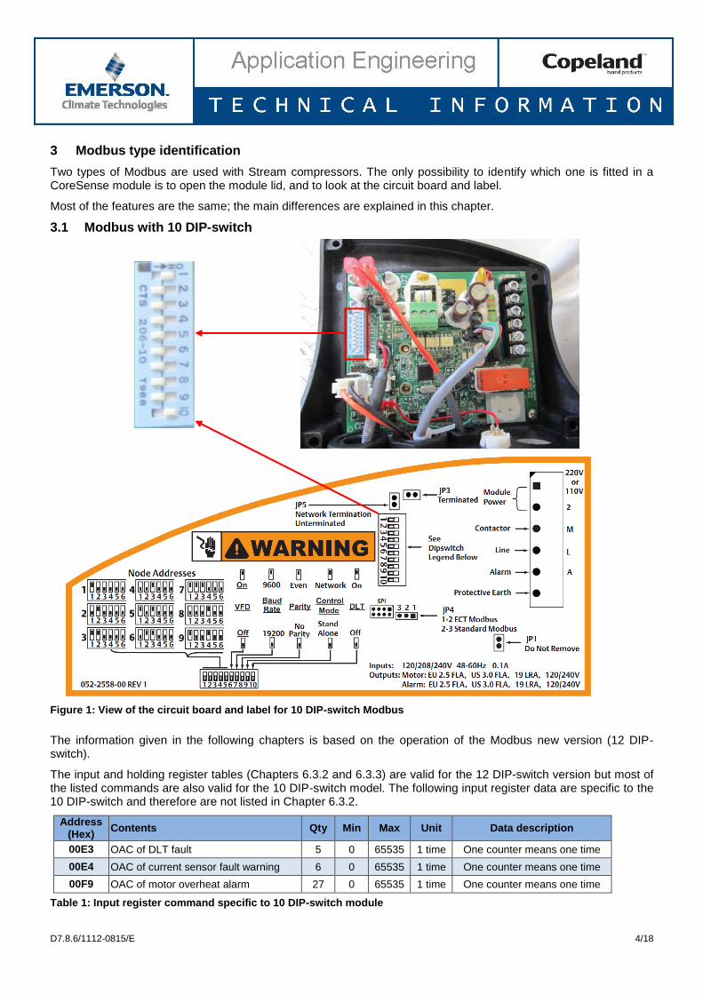
3 Modbus type identification
Two types of Modbus are used with Stream compressors. The only possibility to identify which one is fitted in a CoreSense module is to open the module lid, and to look at the circuit board and label.
Most of the features are the same; the main differences are explained in this chapter.
3.1 Modbus with 10 DIP-switch
Figure 1: View of the circuit board and label for 10 DIP-switch Modbus
The information given in the following chapters is based on the operation of the Modbus new version (12 DIP-switch).
The input and holding register tables (Chapters 6.3.2 and 6.3.3) are valid for the 12 DIP-switch version but most of the listed commands are also valid for the 10 DIP-switch model. The following input register data are specific to the 10 DIP-switch and therefore are not listed in Chapter 6.3.2.
Address (Hex)
Contents Qty Min Max Unit Data description
00E3 OAC of DLT fault 5 0 65535 1 time One counter means one time
00E4 OAC of current sensor fault warning 6 0 65535 1 time One counter means one time
00F9 OAC of motor overheat alarm 27 0 65535 1 time One counter means one time
Table 1: Input register command specific to 10 DIP-switch module
D7.8.6/1112-0815/E 5/18
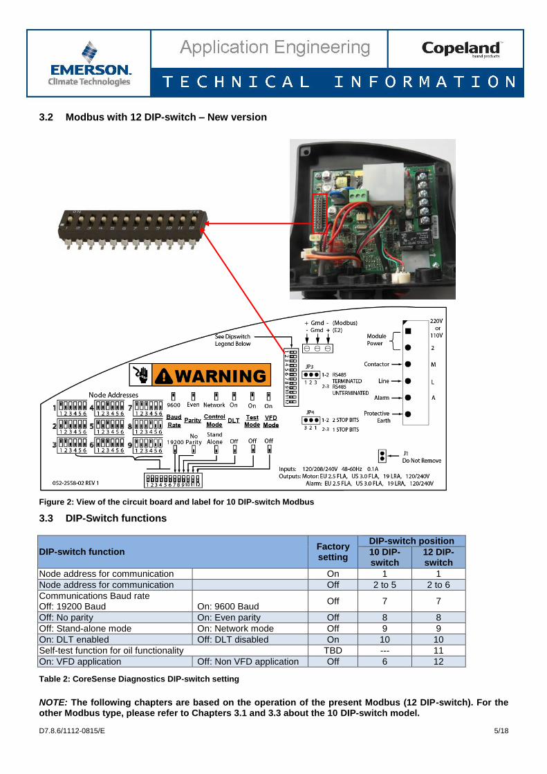
3.2 Modbus with 12 DIP-switch – New version
Figure 2: View of the circuit board and label for 10 DIP-switch Modbus
3.3 DIP-Switch functions
DIP-switch function Factory setting
DIP-switch position
10 DIP-switch
12 DIP-switch
Node address for communication On 1 1
Node address for communication Off 2 to 5 2 to 6
Communications Baud rate Off: 19200 Baud
On: 9600 Baud
Off 7 7
Off: No parity On: Even parity Off 8 8
Off: Stand-alone mode On: Network mode Off 9 9
On: DLT enabled Off: DLT disabled On 10 10
Self-test function for oil functionality TBD --- 11
On: VFD application Off: Non VFD application Off 6 12
Table 2: CoreSense Diagnostics DIP-switch setting
NOTE: The following chapters are based on the operation of the present Modbus (12 DIP-switch). For the other Modbus type, please refer to Chapters 3.1 and 3.3 about the 10 DIP-switch model.
D7.8.6/1112-0815/E 6/18
4 Physical layer
This layer defines the hardware interface to the network.
4.1 Topology
Stream with CoreSense Diagnostics uses the “two-wire” configuration (two signal wires plus a ground). The standard configuration will be to directly wire to the cable forming a daisy-chain.
4.1.1 Wire used
The recommended wire is shielded twisted pair (22 AWG or 0.33 mm2). The shield is also used as the circuit
ground.
Figure 3: Recommended communication wire (shielded twisted pair 22AWG or 0.33 mm
2)
4.1.2 Bus bias
All master devices must provide a means to bias the network. The recommended pull-down on the RS485 “+” output is a 511Ω resistor, but up to a 1KΩ resistor is acceptable. The recommended pull-up resistor on the RS485 “–“ output is a 511Ω resistor, but up to 1KΩ is acceptable. These bias resistors can either be always enabled or they can be enabled through jumpers. The bias is applied at one point in the network.
4.1.3 Termination
All master devices must provide a 150Ω termination resistor. The last slave in the network must have a 150Ω resistor for termination. In this module, there is a jumper provision to enable this termination. The jumper is located between positions 1-2 at “JP3” (see Figure 4). The last CoreSense module in the network shall be populated with a header on this jumper. For the other CoreSense modules in the network, this jumper needs not be populated.
4.2 Data signalling rates
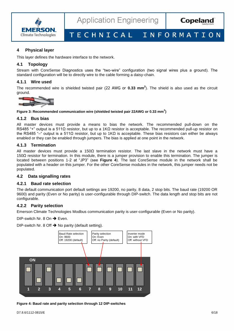
4.2.1 Baud rate selection
The default communication port default settings are 19200, no parity, 8 data, 2 stop bits. The baud rate (19200 OR 9600) and parity (Even or No parity) is user-configurable through DIP-switch. The data length and stop bits are not configurable.
4.2.2 Parity selection
Emerson Climate Technologies Modbus communication parity is user-configurable (Even or No parity).
DIP-switch Nr. 8 On Even.
DIP-switch Nr. 8 Off No parity (default setting).
Figure 4: Baud rate and parity selection through 12 DIP-switches
ON
1 2 3 4 5 6 7 8 9 10 11 12
Baud Rate selection On: 9600 Off: 19200 (default)
Parity selection On: Even Off: no Parity (default)
Inverter mode On: with VFD Off: without VFD
D7.8.6/1112-0815/E 7/18
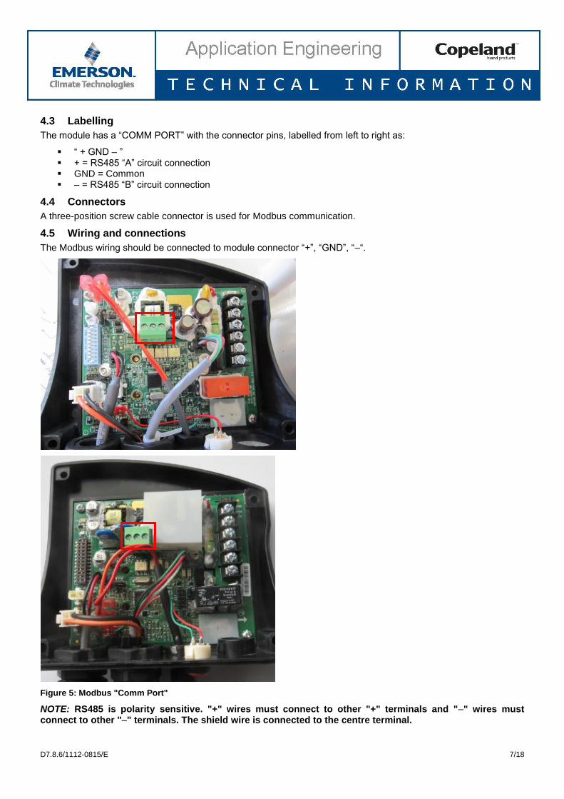
4.3 Labelling
The module has a “COMM PORT” with the connector pins, labelled from left to right as:
“ + GND – ” + = RS485 “A” circuit connection GND = Common – = RS485 “B” circuit connection
4.4 Connectors
A three-position screw cable connector is used for Modbus communication.
4.5 Wiring and connections
The Modbus wiring should be connected to module connector “+”, “GND”, “–“.
Figure 5: Modbus "Comm Port"
NOTE: RS485 is polarity sensitive. "+" wires must connect to other "+" terminals and "–" wires must connect to other "–" terminals. The shield wire is connected to the centre terminal.
D7.8.6/1112-0815/E 8/18
5 Data Link layer
Modbus uses master/slave protocol where there is a single master device that initiates all messages. The Data Link layer defines the reliable transfer of a message transferred from the master to one or more slave devices and the reliable transfer of the response message (when the command message is sent to a single device). The CoreSense Diagnostics module is a slave in the network and the rack controller is the master.
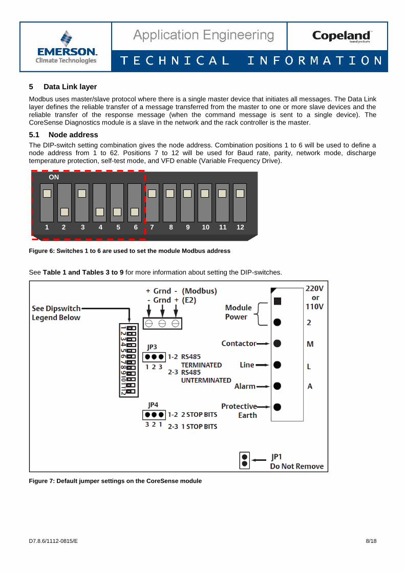
5.1 Node address
The DIP-switch setting combination gives the node address. Combination positions 1 to 6 will be used to define a node address from 1 to 62. Positions 7 to 12 will be used for Baud rate, parity, network mode, discharge temperature protection, self-test mode, and VFD enable (Variable Frequency Drive).
Figure 6: Switches 1 to 6 are used to set the module Modbus address
See Table 1 and Tables 3 to 9 for more information about setting the DIP-switches.
Figure 7: Default jumper settings on the CoreSense module
ON
1 2 3 4 5 6 7 8 9 10 11 12
D7.8.6/1112-0815/E 9/18
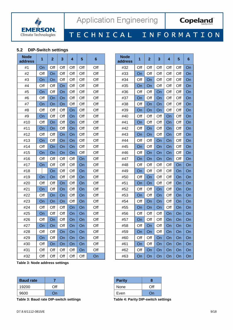
5.2 DIP-Switch settings
Node address
1 2 3 4 5 6
Node address
1 2 3 4 5 6
#1 On Off Off Off Off Off
#32 Off Off Off Off Off On
#2 Off On Off Off Off Off
#33 On Off Off Off Off On
#3 On On Off Off Off Off
#34 Off On Off Off Off On
#4 Off Off On Off Off Off
#35 On On Off Off Off On
#5 On Off On Off Off Off
#36 Off Off On Off Off On
#6 Off On On Off Off Off
#37 On Off On Off Off On
#7 On On On Off Off Off
#38 Off On On Off Off On
#8 Off Off Off On Off Off
#39 On On On Off Off On
#9 On Off Off On Off Off
#40 Off Off Off On Off On
#10 Off On Off On Off Off
#41 On Off Off On Off On
#11 On On Off On Off Off
#42 Off On Off On Off On
#12 Off Off On On Off Off
#43 On On Off On Off On
#13 On Off On On Off Off
#44 Off Off On On Off On
#14 Off On On On Off Off
#45 On Off On On Off On
#15 On On On On Off Off
#46 Off On On On Off On
#16 Off Off Off Off On Off
#47 On On On On Off On
#17 On Off Off Off On Off
#48 Off Off Off Off On On
#18 On Off Off On Off
#49 On Off Off Off On On
#19 On On Off Off On Off
#50 Off On Off Off On On
#20 Off Off On Off On Off
#51 On On Off Off On On
#21 On Off On Off On Off
#52 Off Off On Off On On
#22 Off On On Off On Off
#53 On Off On Off On On
#23 On On On Off On Off
#54 Off On On Off On On
#24 Off Off Off On On Off
#55 On On On Off On On
#25 On Off Off On On Off
#56 Off Off Off On On On
#26 Off On Off On On Off
#57 On Off Off On On On
#27 On On Off On On Off
#58 Off On Off On On On
#28 Off Off On On On Off
#59 On On Off On On On
#29 On Off On On On Off
#60 Off Off On On On On
#30 Off On On On On Off
#61 On Off On On On On
#31 Off Off Off Off On Off
#62 Off On On On On On
#32 Off Off Off Off Off On
#63 On On On On On On
Table 3: Node address settings
Baud rate 7 Parity 8
19200 Off None Off
9600 On Even On
Table 3: Baud rate DIP-switch settings Table 4: Parity DIP-switch settings
D7.8.6/1112-0815/E 10/18
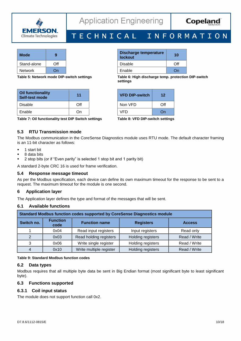
Mode 9 Discharge temperature lockout
10
Stand-alone Off Disable Off
Network On Enable On
Table 5: Network mode DIP-switch settings Table 6: High discharge temp. protection DIP-switch settings
Oil functionality Self-test mode
11
VFD DIP-switch 12
Disable Off Non VFD Off
Enable On VFD On
Table 7: Oil functionality test DIP Switch settings Table 8: VFD DIP-switch settings
5.3 RTU Transmission mode
The Modbus communication in the CoreSense Diagnostics module uses RTU mode. The default character framing is an 11-bit character as follows:
1 start bit 8 data bits 2 stop bits (or if “Even parity” is selected 1 stop bit and 1 parity bit)
A standard 2-byte CRC 16 is used for frame verification.
5.4 Response message timeout
As per the Modbus specification, each device can define its own maximum timeout for the response to be sent to a request. The maximum timeout for the module is one second.
6 Application layer
The Application layer defines the type and format of the messages that will be sent.
6.1 Available functions
Standard Modbus function codes supported by CoreSense Diagnostics module
Switch no. Function
code Function name Registers Access
1 0x04 Read input registers Input registers Read only
2 0x03 Read holding registers Holding registers Read / Write
3 0x06 Write single register Holding registers Read / Write
4 0x10 Write multiple register Holding registers Read / Write
Table 9: Standard Modbus function codes
6.2 Data types
Modbus requires that all multiple byte data be sent in Big Endian format (most significant byte to least significant byte).
6.3 Functions supported
6.3.1 Coil input status
The module does not support function call 0x2.
D7.8.6/1112-0815/E 11/18
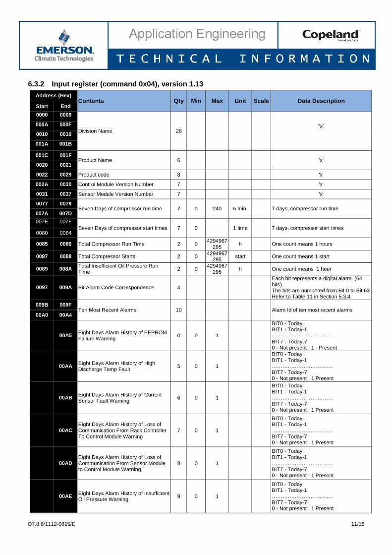
6.3.2 Input register (command 0x04), version 1.13
Address (Hex) Contents Qty Min Max Unit Scale Data Description
Start End
0000 0009
Division Name 28
“x” 000A 000F
0010 0019
001A 001B
001C 001F Product Name 6
'x'
0020 0021
0022 0029 Product code 8 'x'
002A 0030 Control Module Version Number 7 'x'
0031 0037 Sensor Module Version Number 7 'x'
0077 0079 Seven Days of compressor run time 7 0 240 6 min. 7 days, compressor run time
007A 007D
007E 007F
Seven Days of compressor start times 7 0 1 time 7 days, compressor start times 0080 0084
0085 0086 Total Compressor Run Time 2 0 4294967
295 h One count means 1 hours
0087 0088 Total Compressor Starts 2 0 4294967
295 start One count means 1 start
0089 008A Total Insufficient Oil Pressure Run Time
2 0 4294967
295 h One count means 1 hour
0097 009A Bit Alarm Code Correspondence 4
Each bit represents a digital alarm. (64 bits). The bits are numbered from Bit 0 to Bit 63 Refer to Table 11 in Section 5.3.4.
009B 009F Ten Most Recent Alarms 10
Alarm Id of ten most recent alarms
00A0 00A4
00A5
Eight Days Alarm History of EEPROM Failure Warning
0 0 1
BIT0 - Today BIT1 - Today-1 …………………………….. BIT7 - Today-7 0 - Not present 1 - Present
00AA
Eight Days Alarm History of High Discharge Temp Fault
5 0 1
BIT0 - Today BIT1 - Today-1 …………………………….. BIT7 - Today-7 0 - Not present 1 Present
00AB
Eight Days Alarm History of Current Sensor Fault Warning
6 0 1
BIT0 - Today BIT1 - Today-1 …………………………….. BIT7 - Today-7 0 - Not present 1 Present
00AC
Eight Days Alarm History of Loss of Communication From Rack Controller To Control Module Warning
7 0 1
BIT0 - Today: BIT1 - Today-1 …………………………….. BIT7 - Today-7 0 - Not present 1 Present
00AD
Eight Days Alarm History of Loss of Communication From Sensor Module to Control Module Warning
8 0 1
BIT0 - Today BIT1 - Today-1 …………………………….. BIT7 - Today-7 0 - Not present 1 Present
00AE
Eight Days Alarm History of Insufficient Oil Pressure Warning
9 0 1
BIT0 - Today BIT1 - Today-1 …………………………….. BIT7 - Today-7 0 - Not present 1 Present
D7.8.6/1112-0815/E 12/18
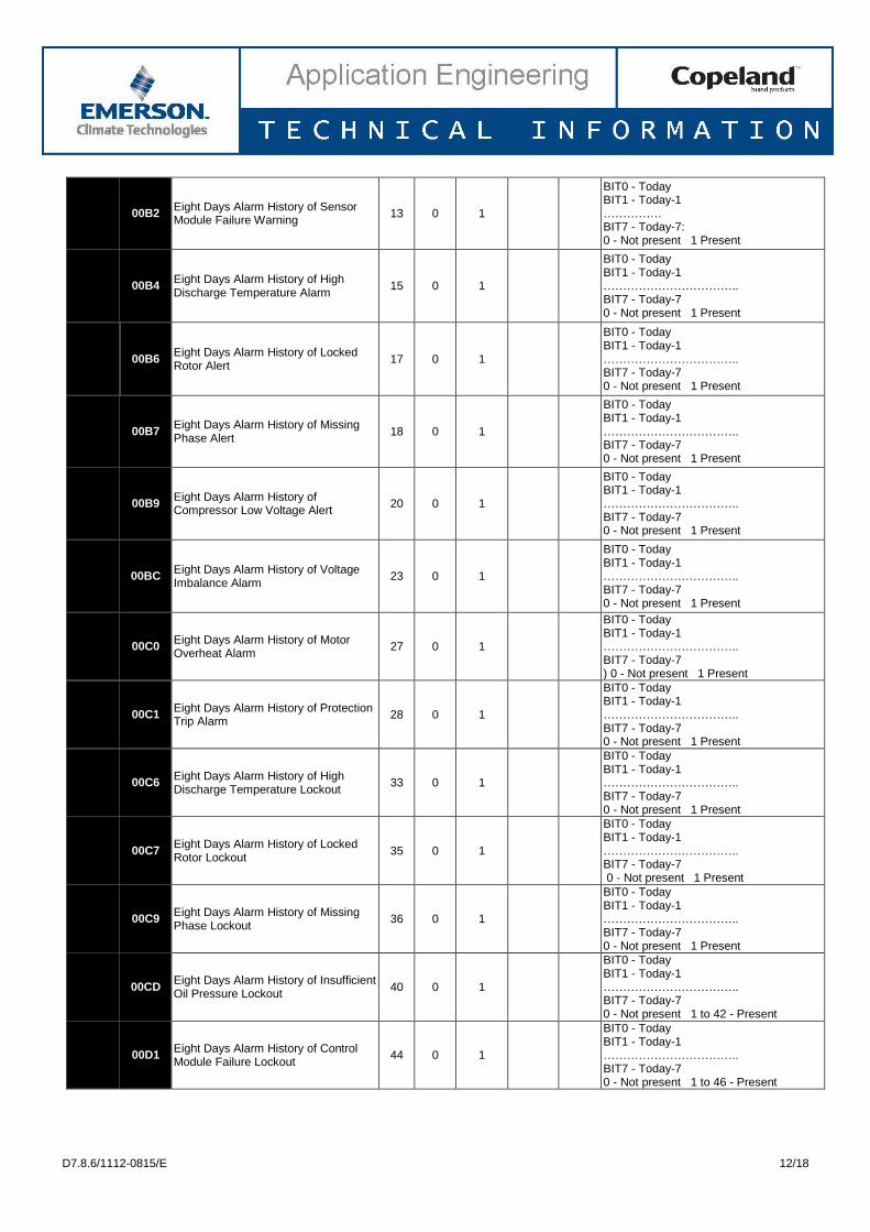
00B2
Eight Days Alarm History of Sensor Module Failure Warning
13 0 1
BIT0 - Today BIT1 - Today-1 …………… BIT7 - Today-7: 0 - Not present 1 Present
00B4
Eight Days Alarm History of High Discharge Temperature Alarm
15 0 1
BIT0 - Today BIT1 - Today-1 …………………………….. BIT7 - Today-7 0 - Not present 1 Present
00B6
Eight Days Alarm History of Locked Rotor Alert
17 0 1
BIT0 - Today BIT1 - Today-1 …………………………….. BIT7 - Today-7 0 - Not present 1 Present
00B7
Eight Days Alarm History of Missing Phase Alert
18 0 1
BIT0 - Today BIT1 - Today-1 …………………………….. BIT7 - Today-7 0 - Not present 1 Present
00B9
Eight Days Alarm History of Compressor Low Voltage Alert
20 0 1
BIT0 - Today BIT1 - Today-1 …………………………….. BIT7 - Today-7 0 - Not present 1 Present
00BC
Eight Days Alarm History of Voltage Imbalance Alarm
23 0 1
BIT0 - Today BIT1 - Today-1 …………………………….. BIT7 - Today-7 0 - Not present 1 Present
00C0
Eight Days Alarm History of Motor Overheat Alarm
27 0 1
BIT0 - Today BIT1 - Today-1 …………………………….. BIT7 - Today-7 ) 0 - Not present 1 Present
00C1
Eight Days Alarm History of Protection Trip Alarm
28 0 1
BIT0 - Today BIT1 - Today-1 …………………………….. BIT7 - Today-7 0 - Not present 1 Present
00C6
Eight Days Alarm History of High Discharge Temperature Lockout
33 0 1
BIT0 - Today BIT1 - Today-1 …………………………….. BIT7 - Today-7 0 - Not present 1 Present
00C7
Eight Days Alarm History of Locked Rotor Lockout
35 0 1
BIT0 - Today BIT1 - Today-1 …………………………….. BIT7 - Today-7 0 - Not present 1 Present
00C9
Eight Days Alarm History of Missing Phase Lockout
36 0 1
BIT0 - Today BIT1 - Today-1 …………………………….. BIT7 - Today-7 0 - Not present 1 Present
00CD
Eight Days Alarm History of Insufficient Oil Pressure Lockout
40 0 1
BIT0 - Today BIT1 - Today-1 …………………………….. BIT7 - Today-7 0 - Not present 1 to 42 - Present
00D1
Eight Days Alarm History of Control Module Failure Lockout
44 0 1
BIT0 - Today BIT1 - Today-1 …………………………….. BIT7 - Today-7 0 - Not present 1 to 46 - Present
D7.8.6/1112-0815/E 13/18
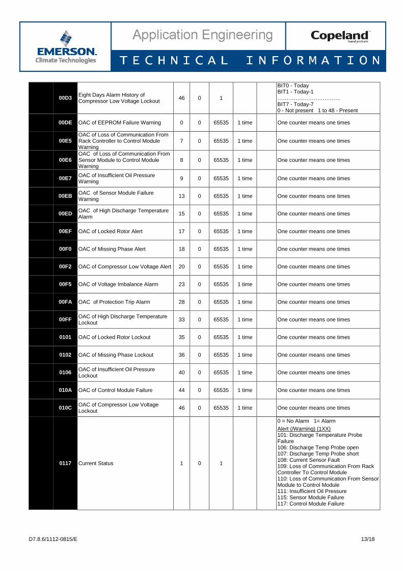
00D3
Eight Days Alarm History of Compressor Low Voltage Lockout
46 0 1
BIT0 - Today BIT1 - Today-1 …………………………….. BIT7 - Today-7 0 - Not present 1 to 48 - Present
00DE OAC of EEPROM Failure Warning 0 0 65535 1 time One counter means one times
00E5
OAC of Loss of Communication From Rack Controller to Control Module Warning
7 0 65535 1 time One counter means one times
00E6
OAC of Loss of Communication From Sensor Module to Control Module Warning
8 0 65535 1 time One counter means one times
00E7
OAC of Insufficient Oil Pressure Warning
9 0 65535 1 time One counter means one times
00EB
OAC of Sensor Module Failure Warning
13 0 65535 1 time One counter means one times
00ED
OAC of High Discharge Temperature Alarm
15 0 65535 1 time One counter means one times
00EF OAC of Locked Rotor Alert 17 0 65535 1 time One counter means one times
00F0 OAC of Missing Phase Alert 18 0 65535 1 time One counter means one times
00F2 OAC of Compressor Low Voltage Alert 20 0 65535 1 time One counter means one times
00F5 OAC of Voltage Imbalance Alarm 23 0 65535 1 time One counter means one times
00FA OAC of Protection Trip Alarm 28 0 65535 1 time One counter means one times
00FF
OAC of High Discharge Temperature Lockout
33 0 65535 1 time One counter means one times
0101 OAC of Locked Rotor Lockout 35 0 65535 1 time One counter means one times
0102 OAC of Missing Phase Lockout 36 0 65535 1 time One counter means one times
0106
OAC of Insufficient Oil Pressure Lockout
40 0 65535 1 time One counter means one times
010A OAC of Control Module Failure 44 0 65535 1 time One counter means one times
010C
OAC of Compressor Low Voltage Lockout
46 0 65535 1 time One counter means one times
0117 Current Status 1 0 1
0 = No Alarm 1= Alarm
Alert (/Warning) (1XX) 101: Discharge Temperature Probe Failure 106: Discharge Temp Probe open 107: Discharge Temp Probe short 108: Current Sensor Fault 109: Loss of Communication From Rack Controller To Control Module 110: Loss of Communication From Sensor Module to Control Module 111: Insufficient Oil Pressure 115: Sensor Module Failure 117: Control Module Failure
D7.8.6/1112-0815/E 14/18
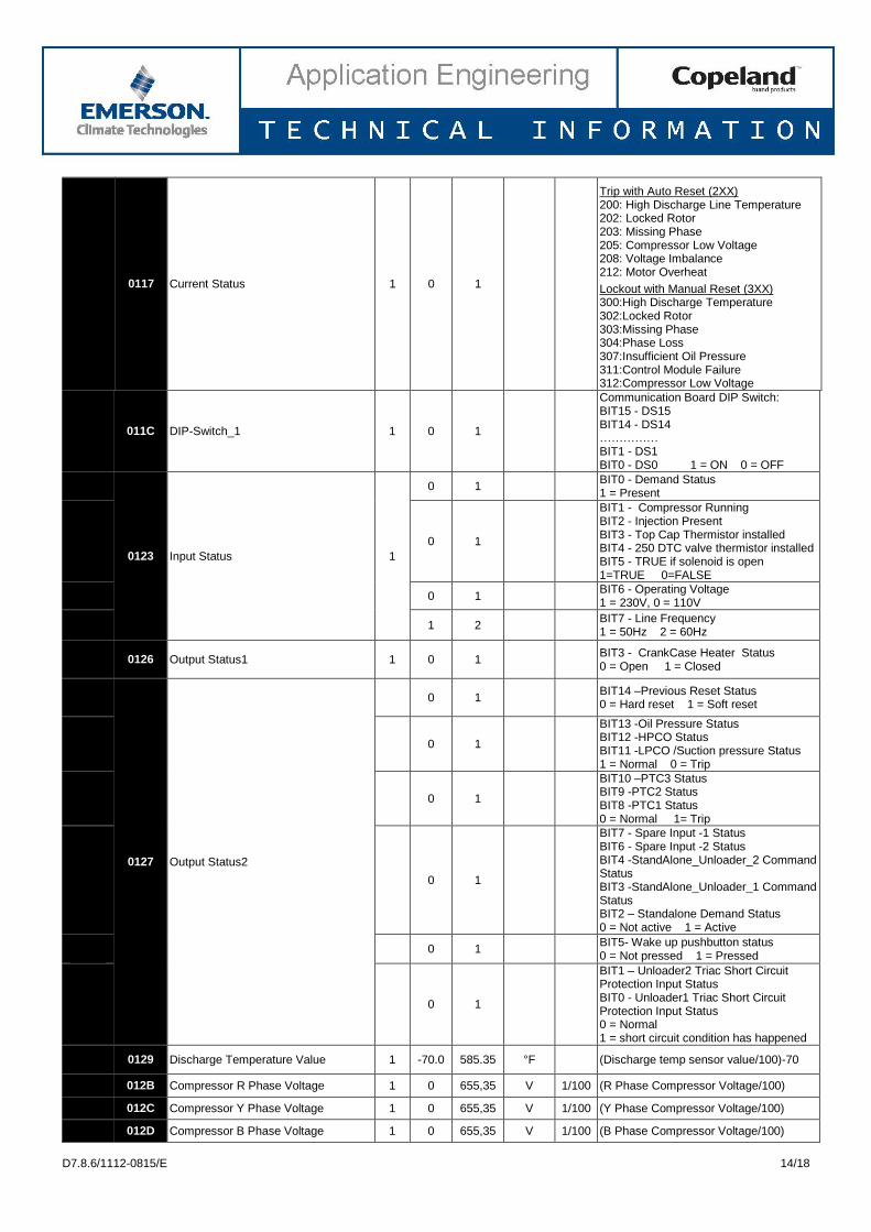
0117 Current Status 1 0 1
Trip with Auto Reset (2XX) 200: High Discharge Line Temperature 202: Locked Rotor 203: Missing Phase 205: Compressor Low Voltage 208: Voltage Imbalance 212: Motor Overheat
Lockout with Manual Reset (3XX) 300:High Discharge Temperature 302:Locked Rotor 303:Missing Phase 304:Phase Loss 307:Insufficient Oil Pressure 311:Control Module Failure 312:Compressor Low Voltage
011C DIP-Switch_1 1 0 1
Communication Board DIP Switch: BIT15 - DS15 BIT14 - DS14 …………… BIT1 - DS1 BIT0 - DS0 1 = ON 0 = OFF
0123 Input Status 1
0 1 BIT0 - Demand Status 1 = Present
0 1
BIT1 - Compressor Running BIT2 - Injection Present BIT3 - Top Cap Thermistor installed BIT4 - 250 DTC valve thermistor installed BIT5 - TRUE if solenoid is open 1=TRUE 0=FALSE
0 1
BIT6 - Operating Voltage 1 = 230V, 0 = 110V
1 2
BIT7 - Line Frequency 1 = 50Hz 2 = 60Hz
0126 Output Status1 1 0 1
BIT3 - CrankCase Heater Status 0 = Open 1 = Closed
0127 Output Status2
0 1
BIT14 –Previous Reset Status 0 = Hard reset 1 = Soft reset
0 1
BIT13 -Oil Pressure Status BIT12 -HPCO Status BIT11 -LPCO /Suction pressure Status 1 = Normal 0 = Trip
0 1
BIT10 –PTC3 Status BIT9 -PTC2 Status BIT8 -PTC1 Status 0 = Normal 1= Trip
0 1
BIT7 - Spare Input -1 Status BIT6 - Spare Input -2 Status BIT4 -StandAlone_Unloader_2 Command Status BIT3 -StandAlone_Unloader_1 Command Status BIT2 – Standalone Demand Status 0 = Not active 1 = Active
0 1
BIT5- Wake up pushbutton status 0 = Not pressed 1 = Pressed
0 1
BIT1 – Unloader2 Triac Short Circuit Protection Input Status BIT0 - Unloader1 Triac Short Circuit Protection Input Status 0 = Normal 1 = short circuit condition has happened
0129 Discharge Temperature Value 1 -70.0 585.35 °F (Discharge temp sensor value/100)-70
012B Compressor R Phase Voltage 1 0 655,35 V 1/100 (R Phase Compressor Voltage/100)
012C Compressor Y Phase Voltage 1 0 655,35 V 1/100 (Y Phase Compressor Voltage/100)
012D Compressor B Phase Voltage 1 0 655,35 V 1/100 (B Phase Compressor Voltage/100)
D7.8.6/1112-0815/E 15/18
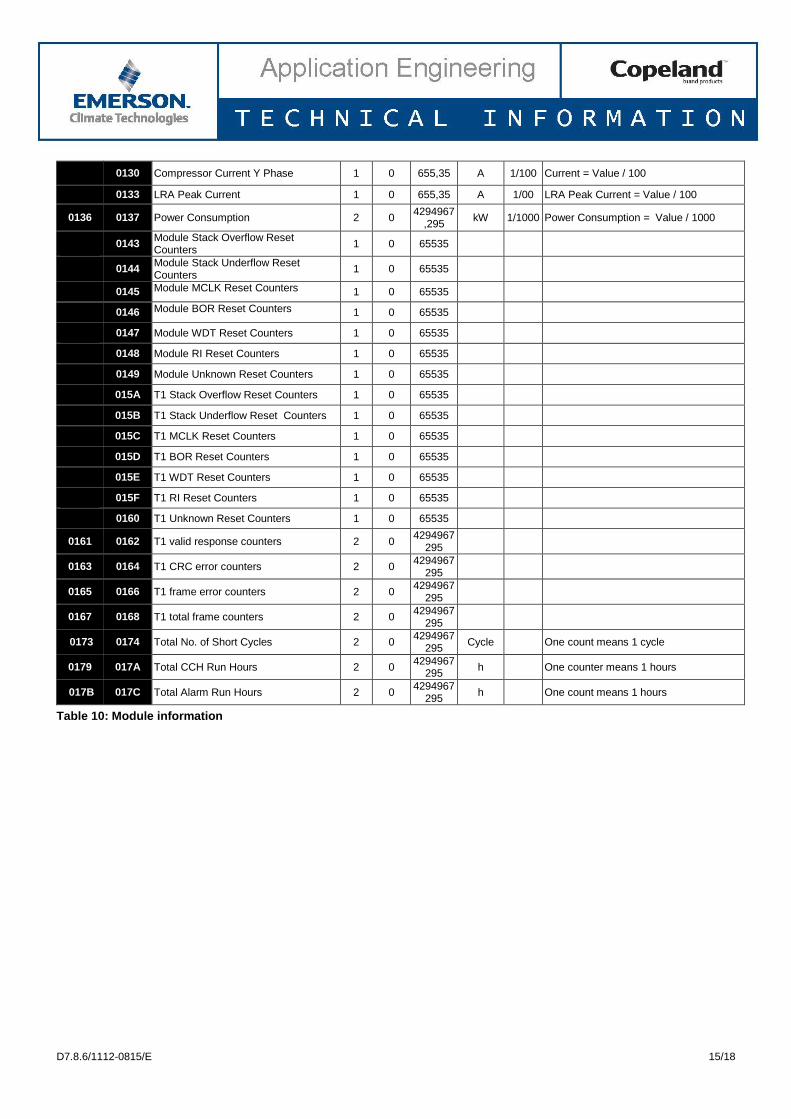
0130 Compressor Current Y Phase 1 0 655,35 A 1/100 Current = Value / 100
0133 LRA Peak Current 1 0 655,35 A 1/00 LRA Peak Current = Value / 100
0136 0137 Power Consumption 2 0 4294967
,295 kW 1/1000 Power Consumption = Value / 1000
0143
Module Stack Overflow Reset Counters
1 0 65535
0144
Module Stack Underflow Reset Counters
1 0 65535
0145 Module MCLK Reset Counters 1 0 65535
0146 Module BOR Reset Counters 1 0 65535
0147 Module WDT Reset Counters 1 0 65535
0148 Module RI Reset Counters 1 0 65535
0149 Module Unknown Reset Counters 1 0 65535
015A T1 Stack Overflow Reset Counters 1 0 65535
015B T1 Stack Underflow Reset Counters 1 0 65535
015C T1 MCLK Reset Counters 1 0 65535
015D T1 BOR Reset Counters 1 0 65535
015E T1 WDT Reset Counters 1 0 65535
015F T1 RI Reset Counters 1 0 65535
0160 T1 Unknown Reset Counters 1 0 65535
0161 0162 T1 valid response counters 2 0
4294967295
0163 0164 T1 CRC error counters 2 0 4294967
295
0165 0166 T1 frame error counters 2 0 4294967
295
0167 0168 T1 total frame counters 2 0 4294967
295
0173 0174 Total No. of Short Cycles 2 0 4294967
295 Cycle One count means 1 cycle
0179 017A Total CCH Run Hours 2 0 4294967
295 h One counter means 1 hours
017B 017C Total Alarm Run Hours 2 0 4294967
295 h One count means 1 hours
Table 10: Module information
D7.8.6/1112-0815/E 16/18
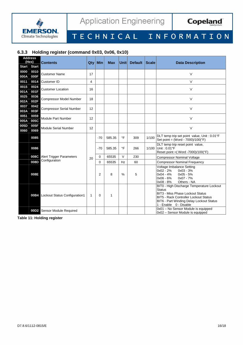
6.3.3 Holding register (command 0x03, 0x06, 0x10)
Address (Hex) Contents Qty Min Max Unit Default Scale Data Description
Start Start
0000 0010 Customer Name 17
'x'
000A 000F
0011 0014 Customer ID 4
'x'
0015 0024 Customer Location 16
'x'
001A 001F
0025 0036 Compressor Model Number 18
'x'
002A 002F
0037 0042 Compressor Serial Number 12
'x'
003A 003F
0051 0059 Module Part Number 12
'x'
005A 005C
005D 005F Module Serial Number 12
'x'
0060 0069
0085
Alert Trigger Parameters Configuration
20
-70 585.35 °F 309 1/100 DLT temp trip set point value, Unit : 0.01°F Set point = (Word - 7000)/100(°F)
0086 -70 585.35 °F 266 1/100 DLT temp trip reset point value, Unit : 0.01°F Reset point =( Word -7000)/100(°F)
008C 0 65535 V 230
Compressor Nominal Voltage
008D 0 65535 Hz 60
Compressor Nominal Frequency
008E 2 8 % 5
Voltage Imbalance Setting 0x02 - 2% 0x03 - 3% 0x04 - 4% 0x05 - 5% 0x06 - 6% 0x07 - 7% 0x08 - 8% Others - NA
00B4 Lockout Status Configuration1 1 0 1
BIT0 - High Discharge Temperature Lockout Status BIT3 - Miss Phase Lockout Status BIT5 - Rack Controller Lockout Status BIT6 - Part Winding Delay Lockout Status 1 - Enable 0 - Disable
00D2 Sensor Module Required
0x01 – No Sensor Module is equipped 0x02 – Sensor Module is equipped
Table 11: Holding register
D7.8.6/1112-0815/E 17/18
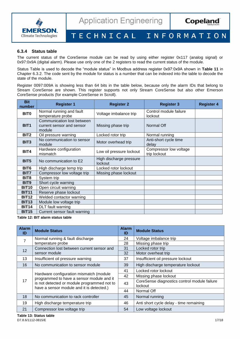
6.3.4 Status table
The current status of the CoreSense module can be read by using either register 0x117 (analog signal) or 0x97:0x9A (digital alarm). Please use only one of the 2 registers to read the current status of the module.
Status Table is used to decode the “module status” in Modbus address register 0x97:0x9A shown in Table 11 in Chapter 6.3.2. The code sent by the module for status is a number that can be indexed into the table to decode the state of the module.
Register 0097:009A is showing less than 64 bits in the table below, because only the alarm IDs that belong to Stream CoreSense are shown. This register supports not only Stream CoreSense but also other Emerson CoreSense products (for example CoreSense in Scroll).
Bit number
Register 1 Register 2 Register 3 Register 4
BIT0 Normal running and fault temperature probe
Voltage imbalance trip Control module failure lockout
BIT1 Communication lost between current sensor and sensor module
Missing phase trip Normal Off
BIT2 Oil pressure warning Locked rotor trip Normal running
BIT3 No communication to sensor module
Motor overhead trip Anti-short cycle time delay
BIT4 Hardware configuration mismatch
Low oil pressure lockout Compressor low voltage trip lockout
BIT5 No communication to E2 High discharge pressure lockout
BIT6 High discharge temp trip Locked rotor lockout
BIT7 Compressor low voltage trip Missing phase lockout
BIT8 System trip
BIT9 Short cycle warning
BIT10 Open circuit warning
BIT11 Reserve phase lockout
BIT12 Welded contactor warning
BIT13 Module low voltage trip
BIT14 DLT fault warning
BIT15 Current sensor fault warning
Table 12: BIT alarm status table
Alarm ID
Module Status Alarm
ID Module Status
7 Normal running & fault discharge temperature probe
24 Voltage imbalance trip
28 Missing phase trip
12 Connection lost between current sensor and sensor module
31 Locked rotor trip
32 Motor overheat trip
13 Insufficient oil pressure warning 37 Insufficient oil pressure lockout
16 No communication to sensor module 39 High discharge temperature lockout
17
Hardware configuration mismatch (module programmed to have a sensor module and it is not detected or module programmed not to have a sensor module and it is detected.)
41 Locked rotor lockout
42 Missing phase lockout
43 CoreSense diagnostics control module failure lockout
44 Normal Off
18 No communication to rack controller 45 Normal running
19 High discharge temperature trip 46 Anti short cycle delay - time remaining
21 Compressor low voltage trip 54 Low voltage lockout
Table 13: Status table
D7.8.6/1112-0815/E 18/18
7 Troubleshooting
If the communication module does not respond, here is a list of general troubleshooting tips:
1. Check the wiring connection. Ensure the wiring is correctly connected and the connector is not loose. 2. Check the power to the CoreSense module. Check the power supply line and ensure the power is on and
the green LED is on. 3. Check the module network address. The address should match the address that the master has requested.
The valid addresses are 1 to 31. “0” is not a valid address. 4. Check your master data format setting. Ensure the master node data format setting to: RTU mode, 1 start
bit, 8 data bits, no parity bit, and 2 stop bits. 5. Check the master node baud rate setting. Set your master node baud rate as 19200 and then try to
communicate with the module. If the module does not respond, then set to 9600 baud rate and try it again.
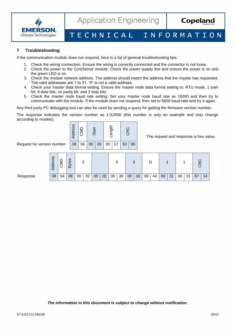
Any third party PC debugging tool can also be used by sending a query for getting the firmware version number.
The response indicates the version number as 1.01R00 (this number is only an example and may change according to models).
Addre
ss
CM
D
Sta
rt
Leng
th
CR
C
The request and response is hex value.
Request for version number 08 04 00 00 00 07 50 95
Addre
ss
CM
D
Byte
s
2 0 3 D 1 1
CR
C
Response 08 04 0E 00 32 00 2E 00 30 00 33 00 44 00 31 00 31 87 14
The information in this document is subject to change without notification.