Embed Size (px)
Citation preview

TM 9-1660
____WAR DEPARTMENT
0 —
TECHNICAL MANUAL
ORDNANCE MAINTENANCE
SOUND LOCATOR M2
WAR DEPARTMENT,WASHINGTON, October 9, 1940.
TM 9-1660, Ordnance Maintenance, Sound Locator M2, is publishedfor the information and guidance of maintenance personnel. Thismanual was prepared by the Sperry Gyroscope Company, Incorporated, for the use of the War Department.Instructions contained in this manual are to be followed to thesame extent as instructions in any other Technical Manual.
[A. G. 062.11 (10-9-40).]
BY ORDER OF THE SECRETARY OF WAR IG. C. MARSHALL,
Chief of Staff.OFFICIAL :
E. S. ADAMS,Major General,Tfi-e Adjutant General.
DISTRIBUTION :B4(2);IR4(l);Bn9 (3);IC9 (4).(For explanation of symbols, see F M 21-6.)
M558446

FOKEWOKD
1. TM 9-1660 contains information for guiding qualified maintenance personnel in locating and correcting such trouble as may be
encountered with the sound locator M2. Maintenance personnel,whether of the using arm or of the Ordnance Department, may be
qualified for this work either through the successful accomplishmentof a recognized course of instruction in sound locator maintenance,or through adequate experience in the type of operation to be undertaken. A recognized course of instruction is defined as one havingthe approval of the Chiefs of Ordnance and Coast Artillery forqualification in sound locator repair. Determination of adequateexperience will be made in each case by the responsible ordnanceofficer. The responsible ordnance officer will take necessary actionfor maintenance requiring facilities beyond those available locally.2. The material herein is divided into the following parts :
Section I—Introduction.Section II—Maintenance and inspection.Section III—Disassembly and reassembly.Section IV—Trouble shooting.
3. Successful servicing of the sound locator requires patience andattention to detail as well as an understanding of the interrelationsof the component parts and adjustments, so it is essential that servicemen acquaint themselves with the purpose, functions, and limitationsof each of the sound locator mechanisms. It is recommended thatTM 9-360, 3" AA gun materiel, which includes description, operation,disassembling for transportation, check tests, and care and preservation, TM 9-2660, and sections II and III of this manual be carefully studied before referring to section IV, trouble shooting. Inthis way service personnel will become familiar with the entire instrument and will be in a position to inspect and apply the correct serviceprocedure to any particular part to be repaired. TM 9-2660, Instruction Guide, Sound Locator M2, explains the principles of operation of the sound locator and gives a detailed description of its parts.It contains the material previously given in part I of the soundlocator handbook.
4. Adjustment and repair of the sound locator mechanism, especially those of the corrector and pantograph drives, will not be attemptedby the using arms, except by personnel who have been qualified forthis work as set forth herein.
in
CONTENTS Page
AUTHORIZATION IFOREWORD inCONTENTS v
LIST OF ILLUSTRATIONS ; vSECTION I—Introduction 1
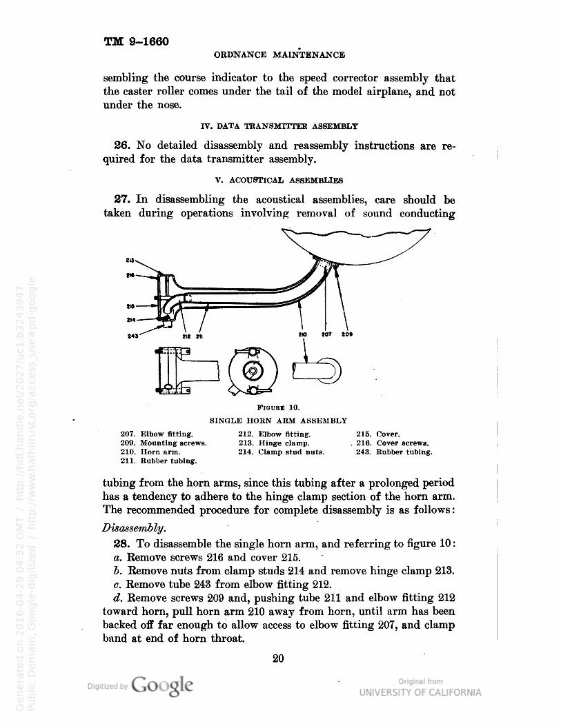
SECTION II—Maintenance and inspection:I. Main case assembly 2
II. Corrector drive assembly 2
III. Pantograph drive assembly 5
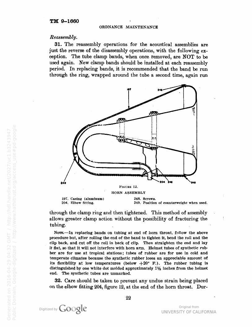
IV. Data transmitter assembly: 5
V. Acoustical assemblies 7
VI. Operation tests 7
VII. Spare parts and tools 9
SECTION III—Disassembly and reassembly for servicing, replacementand adjustment of parts:
I. Main case assembly 11
II. Corrector drive assembly 12
III. Pantograph drive assembly 18
IV. Data transmitter assembly 20
V. Acoustical assemblies 20
VI. Platform assembly and column 23
SECTION IV—Trouble shooting:I. Main case assembly 23
II. Corrector drive assembly • 24
III. Pantograph drive assembly 24
IV. Data transmitter assembly 24
V. Acoustical assemblies 26
APPENDIX A—References 27
APPENDIX B—Operation at extreme temperatures 28
LIST OF ILLUSTRATIONS
Figure TITLESound locator M2 Frontispiece
1 Main case assembly (right side—sectional) J 3
2 Corrector assembly (front view) 4
3 Main case assembly (front—sectional) 6
4 Data transmitter assembly 12
5 Corrector drive assembly 13
6 Open sight assembly 15
7 Corrector assembly (top view) 17
8 Pantograph drive assembly 18
9 Pantograph drive case 19
10 Single horn arm assembly 2011 Double horn arm assembly 21
12 Horn assembly, 2213 Speed corrector assembly . 2814 Schematic wiring diagram 29
15 Schematic gearing diagram 30

Sound locator M2.
VI
TM 9-1660SOUND LOCATOR M2
SECTION I
INTRODUCTION
1. Field servicing will include replacement of motor brushes, periodic checking and cleaning of electrical contacts, special lubricationservice, and other maintenance, inspection, replacement, and adjustment operations. It is recommended that periodic checks (at periodsdetermined by service conditions) be made to insure that the soundlocator is in satisfactory working condition. Each instrument isthoroughly checked for proper adjustment prior to leaving the factoryand no readjusting should be done except as outlined in this manual
and/or at the discretion of the officer in charge of maintenance. Acheck of the accuracy of data transmission is made by means of asearchlight or a test station which corresponds to a searchlight datareceiving system. The procedure for making this check is outlined insection II of this manual.2. Spare parts and tools, sufficient for normal field servicing operations, are contained in the wrapper and spare parts box inside of thestowage box. In any operation involving the removal of cover plates,special precautions should be observed to prevent dust, dirt or otherforeign matter from entering the mechanism.3. Disassembly and reassembly instructions are included for refer
ence, in event of damage to the sound locator necessitating replacement or repair of damaged parts. To facilitate repairs, spare partsare stored in Ordnance supply depots and some complete assembliescan be supplied upon requisition. For identification of parts referenceshould be made to the manufacturer's parts list.
SECTION IIMAINTENANCE AND INSPECTION
1. In addition to the routine maintenance instructions outlined inTM 9-2660, Instruction Guide, Sound Locator M2, the sound locatorshould be subjected to periodic inspection and maintenance check, dependent on service conditions. This procedure should also be appliedafter disassembly and reassembly operations. All mechanisms, adjustments, and settings should be carefully checked and all partsshould be inspected for lubrication, fit, and placement.
TM 9-1660ORDNANCE MAINTENANCE
3. It is recommended that the cleaning of lubricated parts be donewith solvent, dry cleaning*. Parts so cleaned should then be thoroughly dried and relubricated. Instrument oil may be used for balland sleeve bearings. Andok "C" grease** is recommended for lubrication of the pantograph drive chains. After lubrication of a ballbearing, a coat of the above grease should be applied to the outsideto afford additional protection by acting as a semiseal. Instructionsfor operation at extreme temperatures are in appendix B.
I. MAIN CASE ASSEMBLY
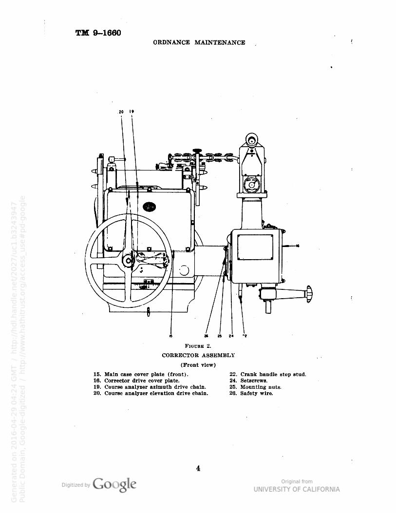
3. Kemove front and rear cover plates 15 and 38, respectively,figure 1.4. Inspect all gears, ball bearings, and shaft bearings for lubrication or wear. Check all taper pins, keys, and set screws for placementand tight fit.5. Check drive chains 19 and 20, figure 2, for proper lubricationand direction of travel. These chains, if correctly installed, shouldoperate the upper sprockets 126 and 124, figure 8, in such a mannerthat the sprockets will turn counterclockwise when viewed from theelevation rack side of the main case, for decreasing azimuth orelevation.
6. Check condition of slip rings 61, figure 1. Clean with carbon
tetrachloride, making certain that surfaces are completely clean anddry before applying any electrical power. Check resistors for continuity and resistance by means of volt-ohmmeter supplied with thisequipment. See wiring diagram on inside of cover plate 15, figure 2.
H. CORRECTOR DRIVE ASSEMBLY
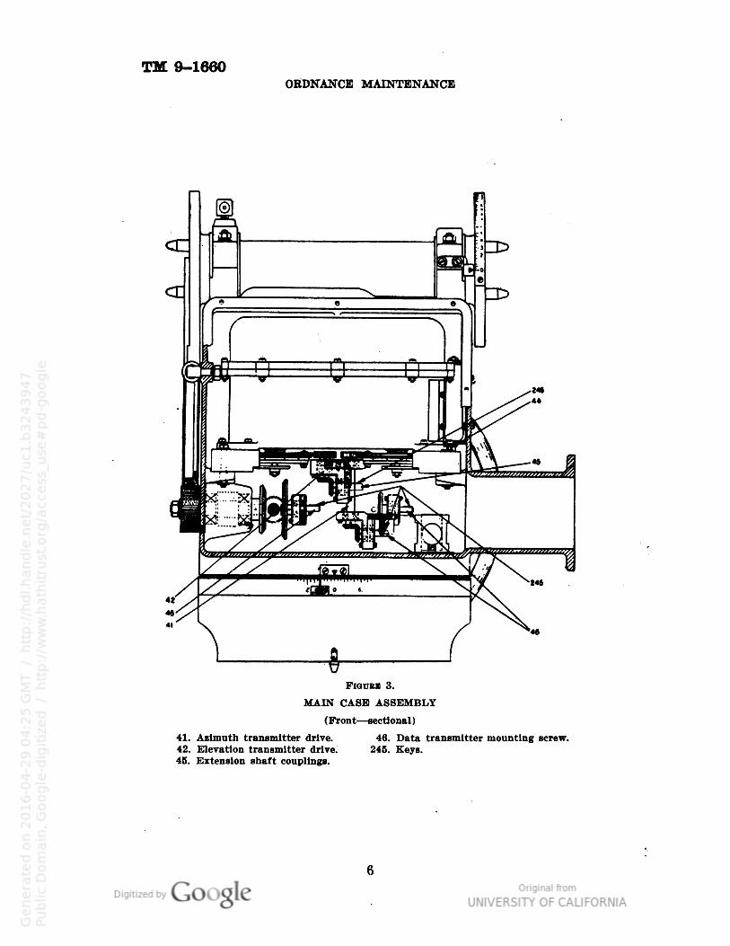
7. Remove corrector drive cover plate 16, figure 2, and inspect rackfind drive shaft bearings, as well as pinion and drive gears for lubrication or wear.8. Check corrector drive mechanism to see that there is no lost motion or binding. Should excessive lost motion be evidenced, the corrector drive mechanism should be thoroughly checked for loose, sheared,or missing taper pins or setscrews, particularly between the azimuthand elevation transmitter drives 41 and 42, respectively, figure 3, andthe respective transmitters. Lost motion may also result from loose
•Any standard Stoddard solvent may be used. In emergency, a good grade of gasolinemay be used but Is not recommended. In no case should a solvent having rustingproperties be used."Andok "C" is the trade name for a grease manufactured by the Standard Oil Companyof New Jersey. If not available a good grade of petrolatum (vaseline) may be used.
2

TM 9-1660SOUND LOCATOR M2
MAIN CASE ASSEMBLY
(Right side—sectional)15. Cover plate— front.38. Cover plate— rear.
45. Extension shaft couplings.61. Slip rings.
463650°
TM 9-1660ORDNANCE MAINTENANCE
20 19
CORRECTOR ASSEMBLY
(Front view)
15. Main case cover plate (front).16. Corrector drive cover plate.19. Course analyzer azimuth drive chain.20. Course analyzer elevation drive chain.
22. Crank handle stop stud.24. Setscrews.25. Mounting nuts.26. Safety wire.

TM 9-1660SOUND LOCATOR M2
couplings on the extension shafts between the drive mechanisms and
elevation and azimuth control handwheels.
9. Inspect gears and bearings in the open sight assembly for lubrication or wear. The sight mirror should also be checked for mountingrigidity and cleanliness of surface. Caution: Do not attempt to liftopen sight assembly off corrector drive case unless complete readjustment of corrector drive assembly is contemplated.10. Check sight mirror and corrector handle and knob adjustmentas outlined in subsection VI, Operation Tests.11. Reference should be made to paragraph 2, page 2, for cleaningand lubrication information.
III. PANTOGRAPH DRIVE ASSEMBLY
12. Check pantograph structure for distortion by measuring thedistance between pantograph pointer and the center of the sight mirrorfor all positions of elevation. This distance should be 7.5 inches withno speed or parallax correction set in. This dimension is given asa guide. If the results of check problem tests are satisfactory, slightinaccuracy in this dimension may be disregarded.13. Inspect all gears, bearings, sprockets, rollers, and drive chainsfor lubrication or wear. Reference should be made to paragraph 2.page 2. for cleaning and lubrication information.14. Inspect resolving ball 131, figure 9, and its supporting bowl fordirt or gummy lubricant. Clean and relubricate with light machineoil as indicated in paragraph 2, page 2.15. Check mechanism for loose, sheared, or missing taper pins andset screws.
NOTE: It is recommended that light instrument oil be used for lubrication ofresolving ball and associated rollers and supporting bearing bowl in very coldclimates. Medium lubricating oil may be used in very warm climates.
IV. DATA TRANSMITTER ASSEMBLY*
16. Inspect repeater brushes and clean or replace as required.17. Check brush and spring assembly to make certain tension issufficient to maintain constant contact on slip rings. Brushes shouldbe inspected for cleanliness and wear. If new brushes are necessary,change as required.18. Inspect all terminal blocks and terminals for dirty or corrodedcontacts. Clean all terminals and blocks, making certain that no oilor grease is left on block.
•This assembly includes units which are standard self-synchronous repeaters used astransmitters. They will be referred to in this text as repeaters.
TM 9-1660ORDNANCE MAINTENANCE
ft) Ai
g>)
(0)
ID
ID
FlGUEB 3.
MAIN CASE ASSEMBLY
(Front—sectional )
41. Azimuth transmitter drive. 46. Data transmitter mounting screw.42. Elevation transmitter drive. 245. Keys.45. Extension shaft couplings.
TM 9-1660SOUND LOCATOR M2
19. Using a continuity meter or ohmmeter, check continuity of repeater windings to determine the presence of grounds or short circuits.Ohmmeter tests should show the following resistances :
Between Approximate resistanceterminals in ohms1-2 24
2-3 24
3-1 24
4-5 16
20. Check the control cable between each of the 10 conductors andthe main case for grounded circuits, and from end to end of each conductor for continuity.
NOTE.—Using an ohmmeter, a reading of infinity will indicate absence of groundsand a low reading will indicate a closed circuit. If available, a 500-volt, d-cmegger may be used to measure the insulation resistance between each point ofthe 10-conductor cable and the main case. The minimum acceptable value is2 megohms.
V. ACOUSTICAL ASSEMBLIES
21. Cover plates 215 and 227, figures 10 and 11, respectively, should
be removed, and the elbow fittings inspected for proper fit and condition. If required, the soundproofing material should be replaced.22. All horns should be inspected, inside and out, for fracture orimproper assembly.23. Inspect all external flexible tubing for deterioration, fracture,or stoppage due to presence of foreign material or water in tubes. Thislatter inspection should be made by listening to some prearrangedsound source.24. When acoustical assemblies are disassembled for any purposesuch as repair, the opportunity should be taken to inspect and cleanall parts.
VI. OPERATION TESTS
A. Clamp locks
25. Caution: Do not force hand wheels. Tighten elevation clamplock and attempt to turn elevation handwheel, to determine amountof friction. This friction lock and the azimuth friction lock weredesigned, not to "lock" the controls, but to make accidental movementunlikely.26. Tighten azimuth clamp lock and attempt to turn azimuthhandwheel to determine amount of friction.
TM 9-1660ORDNANCE MAINTENANCE
B. Course indicator
27. Tighten elevation lock and loosen azimuth lock.28. Train sound locator clockwise to increase azimuth. The courseindicator should align itself parallel to the elevation axis within±2° and point to the right*.29. Train sound locator counterclockwise to decrease azimuth.The course indicator should align itself parallel to the elevation axis±2° and point to the left*.30. Tighten azimuth lock and loosen elevation lock.31. Increase elevation. The course indicator should align itselfperpendicular to the elevation axis and point toward the elevationoperator.32. Decrease. elevation. The course indicator should align itselfperpendicular to the elevation axis and point away from the elevationoperator.
0. Parallax pointer
33. Tighten elevation lock and loosen azimuth lock.34. Note the direction of the parallax pointer. It should remainpointing in the same direction, relative to some external object,regardless of azimuth movements of the sound locator.
D. Test problems**
35. Connect the sound locator to a test station consisting of, orequivalent to, a searchlight data receiving system. Rotate the sound
locator to increasing azimuth and/or elevation. Rotation of thetest station by the same amount should maintain the zero readerindicator at center.36. Check the accuracy of the data transmission system by movingthe sound locator in suitable steps and then moving the test stationto center the zero reader indicator. Comparison of the dial readingsof the sound locator and the test station, in azimuth and elevation,will indicate the accuracy of the data transmission.37. Lock the sound locator at zero azimuth and zero elevation. Setthe parallax and speed settings to zero. Center the pantographpointer on the cross lines of the sight mirror by means of the corrector handle and knob. Then set the test station to zero without
*The left and right directions of the course indicator are to be taken as viewed fromthe elevation side of the sound locator."Additional problems are in the rear of TM 9-2660, Instruction Guide, Sound Locator M2.
TM 9-1660SOUND LOCATOR M2
disturbing the sound locator. Set the speed setting to 400 miles perhour on the course indicator and point it to the right as viewed fromthe elevation side, and parallel with the elevation axis of the soundlocator. Set the test station to 500 mils and move the corrector handle clockwise until the zero reader indicator is centered. The pantograph pointer should appear centered in the cross lines of the mirrorto within % the diameter of the pointer.38. Reverse the course indicator, that is
,
point it to the left andparallel with the elevation axis of the sound locator. Set the teststation to 5900 mils and move the corrector handle counterclockwiseuntil the zero reader indicator is centered. The pantograph pointershould appear centered on the cross lines of the mirror within % thediameter of the pointer.39. Loosen the elevation lock, elevate to 1600 mils elevation andlock again. With 400 miles per hour speed setting point the courseindicator perpendicular to the elevation axis toward the elevationside of the sound locator. Set the test station to 2100 mils elevationand move the corrector handle to increasing elevation until the zeroreader indicator at the test station is centered. The pantographpointer should appear centered on the cross lines of the mirror towithin y
2 the diameter of the pointer.40. Reverse the course indicator, that is
,
point it away from the elevation side of the sound locator. Set the test station to 1100 mils andmove the corrector handle to decreasing elevation until the zeroreader indicator at the test station is centered. The pantographpointer should appear centered on the cross lines of the mirror towithin y2 the diameter of the pointer.41. Lock the sound locator at zero azimuth, elevation, and parallax.Set the air speed at zero. Center the pantograph pointer on the crosslines of the sight mirror and set the test station to zero. Set theparallax scale to 10, declutch the parallax pointer and set it parallelwith the elevation axis of the sound locator and pointing to theright. Set the test station to 6275 mils and move the corrector handlecounterclockwise until the zero reader indicator at the test station
is centered. The pantograph pointer should appear centered on thecross lines of the mirror to within y2 the diameter of the pointer.
VII. SPARE PARTS AND TOOLS
42. In addition to the accessories and protective coverings suppliedwith each sound locator (See TM 9-2660), the following spare partsand tools are also supplied : »
9
TM 9-1660
Sperry F . A. No.part drawing renumber number quired
158800 1
158801 1
156695 1
165520 1
154739 A177656 1
165521 1
35591 1
35592 1
4680 1
165509 1
165519 A177753 1
153499 1
153826 A177602 1
153842 A277616 2
154108 A177648 1
155352 130
163738 4
121437 A177461 4
156180 1
153736 1
153834 A177608 1
167102 A177767 1
136366 A39125 2
149218 A177471 1
800488 B138252 4
801415 4
173647 1
*164765 1
x V)
•J141444
ORDNANCE MAINTENANCE
Description
Wrench, double end (%"Wrench, double end (%"Wrench, double end (#" x V)Wrench, end (adjustable)Wrench, jackHammerPliers, side cuttingScrew driver (4}£ inch)Screw driver (1M inch)Can, oilWrapperLamp, portable troubleBall, resolvingRoller, resolving ball frictionRoller, resolving ball casterBall, resolving ball bearingBrush ass'y., selsynBrush ass'y., slip ringKit, tube clampPressure rollerSpring, pressure rollerMirror, correctorShield, rubber eyePointer, pantographTubes, helmetl One item only furnishedTubes, helmet] as ordered
Contents, list of spare parts boxVolt-ohmmeter, 0-150 volts a-c (accessory)Pantograph pointer lamp
•Furnished only with sound locators with serial numbers below 376.tNot furnished with sound locators with serial numbers below 376.
SECTION IIIDISASSEMBLY AND REASSEMBLY FOR SERVICING,REPLACEMENT AND ADJUSTMENT OF PARTS
1. Disassembly required for repair or replacement of parts shouldbe undertaken gnly by maintenance personnel qualified as described
in the foreword. The instructions in this section, if followed, will
10
TM 9-1660SOUND LOCATOR M2
simplify such disassembly. Only the more intricate mechanisms arecovered in detail, since reference to the illustrations or to the manufacturer's parts list will give sufficient information to allow servicingof the simpler assemblies and subassemblies. TM 9-2660, section III,describes assemblies mentioned herein. During servicing operationsit is recommended that service personnel DO NOT DISASSEMBLEthe instrument any further than necessary to complete the requiredwork.
2. During repairs, adjustments, or servicing of any kind involvingthe removal of cover plates, care should be taken to prevent dirt orforeign matter from entering the mechanisms. Parts removed fromthe sound locator during disassembly should be placed in a locationthat will protect them from possible damage or dirt. An identifyingtag, bearing the name of the part or subassembly and its location inthe instrument, should be attached to each part.3. As a first step in any extensive disassembly of the sound locatorfor repairs or servicing, the single and double horn arm assembliesand the pantograph should be removed to prevent possible damageto these units. The pantograph should be placed in its stowage box.4. In servicing the sound locator it is recommended that the maincase assembly be left on the column. This tends to simplify overhauland testing of the instrument, since the essential elevation and azimuthmechanisms are readily available for testing the other majorassemblies.
Caution: Do not attempt to operate the sound locator in the fielduntil the inspection and check problems outlined in section I of thisbook have been completed. During servicing, repairs, or parts replacement, care should be taken to prevent damage to gears or shaftswithin the mechanisms as a result of improperly applied force,dropping of tools on the mechanisms or other causes. When removingor replacing gears, do not exert off-center pressure on the gear. Whenremoving or replacing taper pins make certain that the shaft, or part,is securely supported from the side opposite that to which force isapplied.5. The corrector assembly consists of four parts : (1) the main caseassembly, (2) the corrector drive assembly, (3) the pantograph driveassembly, and. (4) the data transmitter assembly. These, with theacoustical assemblies and the platform assembly and column, arecovered in this section.
I. MAIN CASE ASSEMBLY
6. The main case assembly consists of two parts: (1) the stationary assembly (base), and (2) the revolving assembly (housing). The
463650°- -42 3
TM 9-1660ORDNANCE MAINTENANCE
latter is composed of the elevation and azimuth handwheels withassociated gear trains, elevation rack, pinion, elevation scale, datatransmitters and spring brush assembly, spirit level, push buttoncut-out switch, and potentiometer resistors.
7. No detailed disassembly instructions are required for the maincase.
n. CORRECTOR DRIVE 'ASSEMBLY
8. The following procedure is recommended for disassembly andreassembly of the corrector drive assembly, both from correctorassembly and as a unit.
Disassembly.
a. Remove the data transmitter assembly from the main case, asfollows :
(1) Disconnect the wires on terminal block 160. figure 4.*
(2) Remove safety wire and mounting screws 46. figure 3.
198
DATA TRANSMITTER ASSEMBLY
158. Brush and spring assembly.100. Termlnal block.
(3) Bring assembly forward until gears on under side are free.Taking care not to distort the brush springs in the rear 158, figure 4,lift assembly up toward elevation handwheel until unit is clear ofmain case housing. Set transmitter assembly down in an invertedposition to avoid damage to couplings or gears.
•Three-terminal Mock used in sound locators below serial number 376.
12

TM 9-1660
91 93
SOUND LOCATOR M2
102 101 76 86
FlGURE 5.
CORRECTOR DRIVE ASSEMBLY
4.
16.
75.76.
77.
78.
79.
80.
81.
82.
83.
84.
80.
86.
88.
89.
Open sight assembly. 0O.
Cover plate. 91.
Corrector drive housing. 92.
Corrector drive differential. 93.
Outer rack. 95.
Inner rack. 98.
Drive shaft. 99.
Elevation drive extension shafts. 100.
Azimuth drive extension shafts. 101.
1'pper bearing —outer rack. 102.
Upper bearing mounting screws. 103.
Stop screw. 104.
Lower bearing —outer rack. 241.Lower bearing mounting screws. 242.Upper bearing —drive shaft. 250.Upper bearing mounting screws. 251.
Lower bearing —drive shaft.Lower bearing mounting screws.Collar.Taper pin.Rack pinion gear.Differential assembly mounting screwsOpen sight assembly mounting screws.Open sight bearing surface.Lower bearing — inner rack.Lower bearing mounting screws.Inner rack pinion gear.Guide marks.Gear.Gear.Rheostat assembly.Cover of lamp housing.
13

TM 9-1660ORDNANCE MAINTENANCE
5. Remove corrector drive assembly as follows:
(1) Loosen set screws at end of extension shafts 80 and 81. figure 5.
(2) Remove setscrews 24, figure 2.
(3) Remove safety wire 26, and holding corrector drive housing inposition, remove nuts 25.
(4) Holding assembly in normal position, pull it straight out frommain case, being careful not to damage or distort the extension shafts.c. Referring to figure 5, remove cover plate 16.d. Drive out taper pin 93 and remove collar 92.e. Remove screws 91, and allow bearing 90 to drop free. Care shouldbe exercised during this operation to prevent damage to gears andpinions when driving shaft 79 drops out of position.
/. Remove screws 89 and bearing 88.g. Move drive shaft toward bottom of case, tilt away from differential, and lift out.A. Remove screws 83 and bearing 82.
i. Remove screws 86 and bearing 85.
j. Tilt outer rack 77 away from pinion gear 95. and lift rack out ofhousing.k. Remove screws 98 and pull differential assembly 76 straight outfrom housing.I. Remove rheostat assembly 250 from open sight assembly 4. Remove cover 251 and lamp. Disconnect one wire from lamp and onewire from rheostat to enable open sight assembly to be removed.m. Remove screws 99 and lift open sight assembly 4 out of correctordrive housing. Care should be exercised during this operation toprevent damage to inner rack 78. which forms a part of the open sightassembly.n. Remove screws 102 and bearing 101.
9. No detailed instructions are necessary for disassembly of the
open sight assembly.
Reassembly.
10. The following procedure is recommended for reassembly of thecorrector drive assembly as a unit. This is the most critical of alloperations and the following instructions should be closely adhered tofor satisfactory and accurate operation of the unit. Prior to reassembly the sound locator must be leveled, and the mirror must beblocked in its 15° below horizontal position and held thus duringreassembly.11.' If the open sight assembly has been disassembled it should bereassembled as follows :
14

TM 9-1660SOUND LOCATOR M2
a. Referring to figure 6, and to the actual mechanisms, reassemblethe unit in such a manner that when the scribe marks on the mirrorgear sector 114 and the idler gear 113 are in line as observed throughaperture 246, the mirror is at a position 15° below horizontal. This
may also be accomplished with level-protractor or gunner's quadrant,or by use of pointer provided* on the open sight bracket. Thispointer indicates accurately the 15° position of the mirror by coincidence between the pointer and the finished top surface of themirror mounting bracket.b. Assemble inner rack 78 and idler pinion 112 into open sight insuch a manner that, with previous setting maintained, the length of
• 2W
FlGUKE (j.
Ol'EN SIGHT ASSEMBLY
78. Inner rack.112. Idler pinion.113. Idler gear.
114. Mirror gear sector.246. Observation hole for scribe lines.
the inner rack as measured from the under bearing surface of theopen sight assembly 100. figure 5, to the extreme lower end of theinner rack, is 9%2".12. Mount open sight assembly on corrector drive housing. Securely fasten open sight assembly to corrector drive case by means
of screws, 99.Caution: Care must be taken that dimensions and settings outlinedin paragraph 11 are rigidly maintained during this operation.13. Replace and reconnect rheostat assembly, lamp, and cover.
14. Set sound locator at zero elevation, speed, and parallax.15. Mount corrector drive differential 76 in housing 75, and meshinner rack 78 with pinion gear 103. Replace and fasten bearing 101.
•Not provided on sound locators with serial numbers below 376.
15
TM 9-1660ORDNANCE MAINTENANCE
Mount housing on main case. This operation is the reverse of thedisassembly operation outlined in paragraph 8Z>. Fasten extensionshafts of differential assemblies to shaft couplings 45, figures 1 and 3,making certain that all shafts are properly keyed (245, fig. 3) andconnected.
16. Referring to figure 5, turn the open sight assembly in azimuthuntil the guide marks 104 are aligned. Do not disturb this settinguntil azimuth synchronization has been completed. Position corrector handle and knob so that it projects at right angles (90°) to theazimuth heading of the corrector drive housing.a. Replace drive shaft 79 and bearings 88 and 90.
Z>.
Mark a guide line across point of mesh of the two gears 241and 242 with a pencil. Then loosen bearing 90 and, holding driveshaft to prevent its turning, lower it until teeth of the two largegears are unmeshed. Move corrector handle so that the gear 241turns 3 teeth in a clockwise direction, with reference to the guidemarks. Then remesh with gear 242 on drive shaft and fasten bearing90 securely in position.c. This offset procedure compensates for the thickness of thecorrector handle at the point of contact with the stop stud 22, figure
2, resulting in equal displacement of the open sight assembly on
either side of the guide marks 104, figure 5. This completes the
azimuth adjustment of the corrector drive assembly.17. Maintaining all settings and dimensions indicated in paragraph11, and retaining zero elevation, speed, and parallax settings, replaceouter rack 77 and bearings 82 and 85. being careful not to disturbpinion gear 95 when meshing rack with gear.18. Center pantograph pointer on cross lines of mirror; this willresult in mirror being positioned 15° below horizontal. If not certain of pantograph accuracy, leave mirror blocked in position. Remove stop screw 84, and measure distance from top surface o
f bearing82 to upper end of outer rack. This distance must be adjusted to
!%"• To accomplish this remove the upper bearing 82, unmesh rackfrom pinion gear, and raise or lower rack until this dimension is
established. Then remesh rack and pinion gear, replace and fasten
bearing, and replace stop screw.
Caution: Do not run stop screw down, but leave greater part of it
out of bearing.19. Replace data transmitter assembly, reversing the disassembly
operations described in paragraph 8a.20. Unblock mirror, elevate sound locator to 1600 mils, and lock in
position. Run outer rack all the way down, by means of the cor-
1G

TM 9-1660SOUND LOCATOR M2
rector handle knob, until it comes to a stop against the lower bearing85. Using a scribe, mark the rack at a point level with the uppersurface of gear 241. Run outer rack up, by means of knob, until thedistance of travel as measured between the scribe mark and the
upper surface of gear 241 is 2.110". The stop screw 84 should nowbe turned down until it butts against the upper end of the outer rack.Tighten locknut on screw.
FIGURE 7.
CORRECTOR ASSEMRLY
(Top view)
32. Parallel link mounting screws.33. Drive case fork mounting nuts.244. Nut.
21. Unlock sound locator and decrease elevation to zero. It shouldnow be possible to center pantograph pointer on cross lines of sightmirror at any elevation setting, without binding, and to have suchcentering maintained during subsequent operations of the soundlocator.
22. Replace cover plate 16. The corrector drive is now adjustedin azimuth and elevation with respect to the sight mirror and pantograph, and the unit is ready for operation.
17

TM 9-1660ORDKANCE MAINTENANCE
III. PANTOGRAPH DRIVE ASSEMBLY
23. The following procedure is recommended for disassembly andreassembly of the pantograph drive assembly, both from the corrector assembly and as a unit.
FlGUKE 8.
PANTOGRAPH DRIVE ASSEMBLY
29. Drive case.31. Parallel link.121. Cover plate—parallel link.124. Intermediate elevation sprocket.126. Azimuth sprocket.127. Elevation drive sprocket.128. Azimuth drive sprocket.
131. Resolving ball.132. Pressure roller assembly.136. Sprocket mounting screws.137. Parallel link mounting screws.139. Taper pin.146. Mounting screws.
Disassembly.
a. Remove pantograph drive assembly as follows :
(1) Remove pantograph drive chains 19 and 20, figure 2, by open
ing a link of each chain. Care should be taken to prevent unduedistortion of the links, in order that they may be available forreassembly operations.
18

TM 9-1660SOUND LOCATOR M2
(2) Referring to figure 7, remove four screws 32, and two nuts 244.
(3) Holding the assembly in position, remove nuts 33 and liftassembly away from main case. Care should be taken to prevent the
assembly from dropping against the main case during this operation.6. Referring to figure 8, remove screws 146 and very slowly liftthe course indicator assembly off drive case 29. The resolving ballmay now be lifted out.Caution: Use care not to deform any parts while removing thecourse indicator assembly. It must be removed slowly to preventthe spring-backed pressure roller 132 from projecting the resolvingball from the case and scattering the many small ball bearings 151,figure 9, on which it revolves.
IflGURE 9.
PANTOGRAPH DRIVE CASE
131. Resolving ball.151. Ball bearing.
c. To remove parallel link and drive chain housing assembly, thefollowing procedure should be observed. Referring to figure 8:
(1) Remove the cover plate 121.
(2) Remove taper pin 139 from azimuth drive sprocket 128 andremove sprocket. If in so doing it is found necessary first to removethe chain, it may be done by opening a link.
(3) Remove three screws 136 from elevation drive sprocket 127and remove sprocket.
(4) Remove four parallel link mounting screws 137 and removethe collar held by them.
(5) Pull parallel link 31 away from drive case 29.d. Drive chains which have been removed (by opening a link)should be placed in an envelope and tied to the assembly.24. No detailed instructions are necessary for further disassembly.
Disassembly.
25. Reassembly procedure of the pantograph drive assembly is thereverse of the disassembly operations. Care must be taken in reas-
19
TM 9-1660ORDNANCE MAINTENANCE
sembling the course indicator to the speed corrector assembly thatthe caster roller comes under the tail of the model airplane, and notunder the nose.
IV. DATA TRANSMITTER ASSEMBLY
26. No detailed disassembly and reassembly instructions are required for the data transmitter assembly.
V. ACOUSTICAL ASSEMBLIES
27. In disassembling the acoustical assemblies, care should betaken during operations involving removal of sound conducting
207. Elbow fitting.209. Mounting screws.210. Horn arm.211. Rubber tubing.
FIGURE 10.
SINGLE HORN ARM ASSEMBLY
212. Elbow fitting.213. Hinge clamp.214. Clamp stud nuts.
215. Cover.216. Cover screws.243. Rubber tubing.
tubing from the horn arms, since this tubing after a prolonged periodhas a tendency to adhere to the hinge clamp section of the horn arm.The recommended procedure for complete disassembly is as follows :
Disassembly.
28. To disassemble the single horn arm, and referring to figure 10 :a. Remove screws 216 and cover 215.b. Remove nuts from clamp studs 214 and remove hinge clamp 213.c. Remove tube 243 from elbow fitting 212.d. Remove screws 209 and, pushing tube 211 and elbow fitting 212toward horn, pull horn arm 210 away from horn, until arm has beenbacked off far enough to allow access to elbow fitting 207, and clampband at end of horn throat.
20

TM 9-1660SOUND LOCATOR M2
e. Remove tubing from elbow fitting 207 and pull tubing out ofhorn arm.29. To disassemble the double horn arm, and referring to figure 11 :a. Remove screws 228 and cover 227.
&. Remove nuts from clamp studs 224 and 226, and remove hingeclamp 223.
c. Remove two tubes 243 from "Y" fitting 221.
207. Elbow fitting.209. Mounting screws.211. Rubber tubing.219. Horn arm.220. Elbow fitting.
FlGUBE 11.
DOUBLE HORN ARM ASSEMBLY221. "Y" fitting.223. Hinge clamp.. 224. Clamp studs.225. Spacer clamp.226. Clamp studs.
227. Cover.228. Cover screws.230. Mounting screws.243. Rubber tubing.
d. Push "Y" fitting 221 inside.e. Remove spacer clamp 225.
/. Remove one tube 243 from elbow fitting 220.g. Remove screws 209, and pushing tube 211 toward horn, pullhorn arm 219 away from horn until arm has been backed off farenough to allow access to elbow fitting 207 at end of horn throat.h. Remove tubing from elbow fitting 207 and pull tubing out ofhorn arm.i. Remove screws 230 and repeat operation g.30. If disassembly of horn assembly, figure 12, is required, removescrews 248 and casing 197.
21
TM 9-1660ORDNANCE MAINTENANCE
Reassembly.
31. The reassembly operations for the acoustical assemblies arejust the reverse of the disassembly operations, with the following exception. The tube clamp bands, when once removed, are NOT to beused again. New clamp bands should be installed at each reassemblyperiod. In replacing bands, it is recommended that the band be runthrough the ring, wrapped around the tube a second time, again run
249
197. Casing (aluminum)204. Elbow fitting.
FreuHE 12.
HORN ASSEMBLY
248. Screws.249. Position of counterweight when used.
through the clamp ring and then tightened. This method of assemblyallows greater clamp action without the possibility of fracturing thetubing.
NOTE. —In replacing bands on tubing at end of horn throat, follow the aboveprocedure but, after rolling the end of the band to tighten it, bend the roll and theclip back, and cut off the roll in back of clip. Then straighten the end and layit flat, so that it will not interfere with horn arm. Helmet tubes of synthetic rubber are for use at tropical stations; tubes of rubber are for use in cold andtemperate climates because the synthetic rubber loses an appreciable amount ofits flexibility at low temperatures (below +20° P.). The rubber tubing isdistinguished by one white dot molded approximately 1% inches from the helmetend. The synthetic tubes are unmarked.
32. Care should be taken to prevent any undue strain being placedon the elbow fitting 204, figure 12, at the end of the horn throat. Dur-
TM 9-1660SOUND LOCATOR M2
ing reassembling operations, inspection should be made prior to finalassembly of horns and horn arms, to make certain that all elbow fittings, tubing, etc. are securely and completely covered with specifiedsoundproofing material. When replacing a horn assembly, figure 12, alead counterweight is required in each of the two upper horns but noneis required in the lower horn. When a horn is reassembled it is recommended that casing points be coated with an acetate base cement or withshellac before replacing screws 248.
VI. PLATFORM ASSEMBLY AND COLUMN
33. No detailed instructions are required for servicing these units.
SECTION IV
TEOUBLE SHOOTING
1. The sound locator M2 determines and transmits to the searchlight the necessary data to control the searchlight beam with respect toa moving target. It is essential, therefore, that the persons designatedto service the sound locator familiarize themselves with the purposesand functions of the various mechanisms as outlined in TM 9-2660,Instruction Guide, Sound Locator M2. This information is of theutmost importance when a trouble develops, especially when there is
little time to locate and remedy that trouble.2. The troubles which may be encountered in the sound locator canbe divided into two general classifications : First, troubles occurring inan instrument that has been properly adjusted and in which there hasbeen no change in component parts. These may be failures due to accident, or to dirt or other foreign matter in the mechanisms, or to generalwear by extensive use in the field ; second, troubles experienced whenadjusting a sound locator after assembly, or when one or more component parts have been repaired or replaced.3. It is impossible to foretell all troubles which may result fromimproper servicing or unusual field service conditions, but the following possible troubles have been listed to afford the service personnel anopportunity to make an intelligent analysis.
I. MAIN CASE ASSEMBLY
The main case, containing the positive drives of the elevation andazimuth mechanisms, should not prove a source of trouble. It is recommended that all bearings, keys and taper pins be checked for replacement and tight fit, and all moving parts for cleanliness and properlubrication.
23
TM 9-1660ORDNANCE MAINTENANCE
II. CORRECTOR DRIVE ASSEMBLY
Symptom 1—Sight mirror not in adjustment with pantograph pointer
Probable cause Remedy
a. Loose couplings on extension Check all couplings and keys anddrive shafts. tighten set screws.
b. Gear pins sheared from shafts. Check pins and replace as re-c. Inner and outer racks not in quired.adjustment with mirror. Keadjust in accordance with
paragraphs 10 to 21, inclusive, section III.
HI. PANTOGRAPH DRIVE ASSEMBLY
Symptom 1—Intermittent operation of pantograph
Probable cause Remedy
a. Gummy lubricant on resolv- Remove resolving ball in ac-ing ball. cordance with paragraph 236,
page 19, and clean, relubricate,or replace as required.
Z>.
Marred or burred surfaces on Remove resolving ball as indi-resolving ball, drive rollers, or re- cated in Remedy a, and smooth orsolving ball supporting bowl. replace.c. Insufficient tension on pres-' Remove resolving ball and pressure roller bearings. sure roller and increase tension of
the spring or replace it.d. Loose or binding coupling Replace pantograph by loosen -
joints on pantograph structure. ing stud and lifting structure offdrive case.
e. Gear pins sheared from Check pins and replace as re-shafts, quired.
Caution: When removing resolving ball, care should be taken toprevent ball from jumping out of position as a result of spring tension of pressure roller. This will result in projection of roller intothe small bearings in the resolving ball supporting bowl.
IV. DATA TRANSMITTER ASSEMBLY
Symptom 1.—Transmitters fail to operate or have loud hum
Probable cause Remedy
a. No voltage at terminals. Check continuity of powercables and plugs. Check terminalblock wiring in accordance withfigure 14.
24
TM 9-1660SOUND LOCATOR M2
Provable cause
b. Brushes not making contactor set on wrong slip ring.
c. Terminal block wiring incorrect.
d. Open circuit in transmitterwinding.
e. Open circuit in control cable.
/. Short circuit in control cables.
Remedy
Check brush and spring assembly and slip ring contact arrangement. If required, replace brushand spring assembly by first re
moving data transmitter assemblyin accordance with paragraph Sa.
page 12.
Check with wiring diagram,figure 14.
Repair or replace, as required.Remove data transmitter assembly in accordance with paragraph8a, page 12.
Check continuity of cable andplugs and repair or replace.Check insulation between conductors of cable and repair or replace.
Symptom 2.—Transmitters furnish erroneous data
Probable cause.
a. Reversed secondary connec
tions.
&. Incorrect field connections.c. Dirt or foreign matter onspring brushes or slip rings.
d. Poor tension on springbrushes.
e. Loose couplings on extension
drive shafts from corrector drivemechanisms.
/. Gear pins sheared fromshafts.
g. Spring brush contactlined up with slip rings.
not
Remedy
Check with wiring diagram, figure 14, and correct as required.Same as a.Clean with carbon tetrachlorideand dry thoroughly or replacebrushes.
Increase tension or replacebrush assembly.
Inspect all couplings and tighten setscrews.
Check pins and replace as re
quired.Check brush and slip ring alignment.
NOTE. —Periodically, as determined by service conditions, it is recommended thatthe continuity of all motor windings and electrical circuits be tested for openor short circuits to preclude any possibility of failure under acnml service conditions.
25
TM 9-1660ORDNANCE MAINTENANCE
V. ACOUSTICAL ASSEMBLIES
Symptom 1.—Excessive noise
Probable cause Remedy
a. Fracture of external rubber Check condition and repair or
tubing or fittings. replace as required.
b. Fractured horn. Repair or replace with new horn.
NOTE. —Small fractures or holes inhorn may be repaired by filling withputty or plastic wood. Refer to paragraphs 27, 28, 29 and 30, pages 20 and 21.
Symptom 2.—No sound heard
Probable cause Remedy
a. Water in horns and/or rub- Drain horns and tubing andber tubing. blow dry with air.b. Dirt or foreign mater in rub- Blow clear with compressed air.ber tubing or fittings.c. Collapsed fittings or tubing. Inspect and repair or replace
as required. Refer to paragraphs27, 28, 29 and 30, pages 20 and 21.
26
TM 9-1660SOUND LOCATOR M2
APPENDIX A
REFERENCES
1. Standard nomenclature lists:
Until SNL F-176, Sound Locator M2, becomes available, the Manufacturer's Parts List will be used.An up-to-date list of SNL's is maintained as the "Ordnance Publications for Supply Index" (OPSI)2. Technical manuals :
3-inch AA gun materiel TM 9-360Cleaning and preserving materials TM 9-850Instruction guide, sound locator M2 TM 9-2660
27

TM 9-1660ORDNANCE MAINTENANCE
APPENDIX B
OPERATION AT EXTREME TEMPERATURES
1. The sound locator is lubricated at the factory with the lightgrease recommended in section II, and satisfactory operation is obtained for a. temperature range between +10° F. and +120° F. Ifthe sound locator is to be operated at a temperature between + 10° F.
249
249. Machine screw.250. Pin.251. Knob.
SPEED CORRECTOR ASSEMBLY
252. Screw.253. Nut.254. Bushing.
255. Pin.
and — 10° F., difficulty may be experienced, which should becorrected as follows:a. If elevation handwheel turns with difficulty, wash grease fromelevation rack bearing and relubricate with light oil.b. If course indicator movement is sluggish or if the correct courseis not indicated, wash grease from speed corrector mounting plateball bearings and relubricate with light oil.c. If target speed setting screw turns with difficulty, proceed asfollows. With the pantograph off, remove the course indicator(miniature airplane) from the speed corrector assembly, figure 13,by removing two screws 249. Drive out pin 250 by tapping the end
28

TM 9-1660SOUND LOCATOR M2
which is not marked "O." Pull knob 251 forward, drawing screw252, nut 253 and bushing 254 with it
. until the bushing clears thecasting. If necessary, screw nut 253 toward the tail of the airplane,but not far enough to separate it from the screw. Drive out pin 255,
ILLUMINATINGL«UP
Yl
L
•flFMLi L1
; 3
i
c
•HUSHJLOCK OHTRANSMITTER
ct • y
«*
«
\ ?
n
$ — «—TtDlllMLBLOCK IN
AtT—
y- 4
EMmn »«/ [I | "l a Al ft PI IS (t< a
/ I
| / 1/.
FiGTJBE 14.
SCHEMATIC WIRING DIAGRAM
(Sperry drawing No. 800524-B)
remove knob 251 and bushing 254. Wash both bearings clean andrelubricate with light oil. Reassemble the course indicator.
d. If corrector knob turns with difficulty, wash grease from handknob shaft bearings and relubricate with light oil.
29

TM 9-1660ORDNANCE MAINTENANCE
COURSEOf TMOEt
FlGUKE 15.
SCHEMATIC GEARING DIAGRAM
(Sperry drawing No. 644030-A)
2. For extended operation under extreme cold-temperature conditions it may be advisable to relubricate with light oil all ball andsleeve bearings except the two center post ball bearings, whichnormally will not require relubrication.
30
For sale by the Superintendent of Documents, Washington, D. C.


![Daily Los Angeles herald (Los Angeles [Calif.]) 1883-08-19 ...chroniclingamerica.loc.gov/lccn/sn85042459/1883-08-19/ed-1/seq-3.… · WARDEPARTMENT, SIGNAL SER- VICE, U. S. ARMY](https://img.pdfslide.us/doc/110x75/5fc264f1c292de33d8393c0d/daily-los-angeles-herald-los-angeles-calif-1883-08-19-wardepartment-signal.jpg)


![· ARMY REGISTER FOR 1823. 17th CONGRESS.] No, 237. [2d SESSION. ARMYREGISTER FOR TIIE YEAR 1823. COMMUNICATED TO TIlE SENATE, JANUARY 13, 1823. SIR: WARDEPARTMENT,January 10, 1823](https://img.pdfslide.us/doc/110x75/5b3fd43e7f8b9a5e528c9368/-army-register-for-1823-17th-congress-no-237-2d-session-armyregister-for.jpg)
![Daily Los Angeles herald (Los Angeles [Calif.]) 1883-08-05 ...chroniclingamerica.loc.gov/lccn/sn85042459/1883-08-05/ed-1/seq-3.… · WARDEPARTMENT. SIGNAL SER-VICE, U. S. ARMY. DlvUlon](https://img.pdfslide.us/doc/110x75/5f05a71c7e708231d414079a/daily-los-angeles-herald-los-angeles-calif-1883-08-05-wardepartment-signal.jpg)