Embed Size (px)
Citation preview
Ordering Guide For
Linear Displacement Transducers
ABSOLUTE PROCESS CONTROL KNOW WHERE YOU ARE... REGARDLESS
Courtesy of Steven Engineering, Inc. - (800) 258-9200 - [email protected] - www.stevenengineering.com
3 1080 N. Crooks Road • Clawson, MI 48017 • 800.635.0289 • 248.435.0700 • Fax 248.435.8120 • www.ametekapt.com
AUTOMATION & PROCESS TECHNOLOGIES
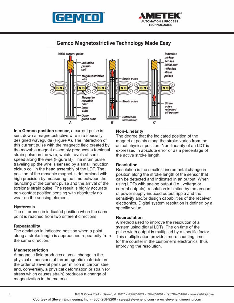
Gemco Magnetostrictive Technology Made Easy
In a Gemco position sensor,acurrentpulseissentdownamagnetostrictivewireinaspeciallydesignedwaveguide(FigureA).Theinteractionofthiscurrentpulsewiththemagneticfieldcreatedbythemovablemagnetassemblyproducesatorsionalstrainpulseonthewire,whichtravelsatsonicspeedalongthewire(FigureB).ThestrainpulsetravelingupthewireissensedbyasmallinductionpickupcoilintheheadassemblyoftheLDT.Thepositionofthemovablemagnetisdeterminedwithhighprecisionbymeasuringthetimebetweenthelaunchingofthecurrentpulseandthearrivalofthetorsionalstrainpulse.Theresultishighlyaccuratenon-contactpositionsensingwithabsolutelynowearonthesensingelement.
HysteresisThedifferenceinindicatedpositionwhenthesamepointisreachedfromtwodifferentdirections.
RepeatabilityThedeviationinindicatedpositionwhenapointalongastrokelengthisapproachedrepeatedlyfromthesamedirection.
MagnetostrictionAmagneticfieldproducesasmallchangeinthephysicaldimensionsofferromagneticmaterialsontheorderofseveralpartspermillionincarbonsteeland,conversely,aphysicaldeformationorstrain(orstresswhichcausesstrain)producesachangeofmagnetizationinthematerial.
Non-LinearityThedegreethattheindicatedpositionofthemagnetatpointsalongthestrokevariesfromtheactualphysicalposition.Non-linearityofanLDTisexpressedinabsoluteerrororasapercentageoftheactivestrokelength.
ResolutionResolutionisthesmallestincrementalchangeinpositionalongthestrokelengthofthesensorthatcanbedetectedandindicatedinanoutput.WhenusingLDTswithanalogoutput(i.e.,voltageorcurrentoutputs),resolutionislimitedbytheamountofpowersupply-inducedoutputrippleandthesensitivityand/ordesigncapabilitiesofthereceiverelectronics.Digitalsystemresolutionisdefinedbyaspecificvalue.RecirculationAmethodusedtoimprovetheresolutionofasystemusingdigitalLDTs.Theontimeofthepulsewidthoutputismultipliedbyaspecificfactor.Thismultiplicationprovidesmorecountingtimeforthecounterinthecustomer’selectronics,thusimprovingtheresolution.
Courtesy of Steven Engineering, Inc. - (800) 258-9200 - [email protected] - www.stevenengineering.com
31080 N. Crooks Road • Clawson, MI 48017 • 800.635.0289 • 248.435.0700 • Fax 248.435.8120 • www.ametekapt.com
AUTOMATION & PROCESS TECHNOLOGIES
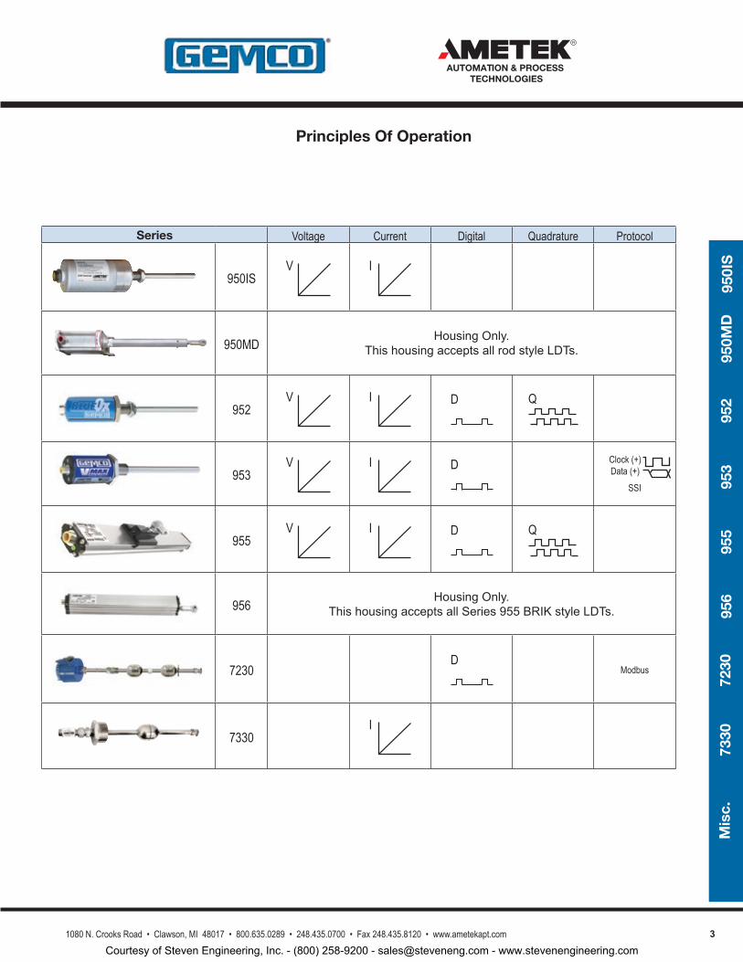
Series Voltage Current Digital Quadrature Protocol
950ISV I
950MD HousingOnly.ThishousingacceptsallrodstyleLDTs.
952V I D Q
953V I D Clock (+)
Data (+)SSI
955V I D Q
956 HousingOnly.ThishousingacceptsallSeries955BRIKstyleLDTs.
7230D
Modbus
7330I
950I
S95
0MD
952
953
955
956
7230
7330
Mis
c.
Principles Of Operation
Courtesy of Steven Engineering, Inc. - (800) 258-9200 - [email protected] - www.stevenengineering.com
4 1080 N. Crooks Road • Clawson, MI 48017 • 800.635.0289 • 248.435.0700 • Fax 248.435.8120 • www.ametekapt.com
AUTOMATION & PROCESS TECHNOLOGIES
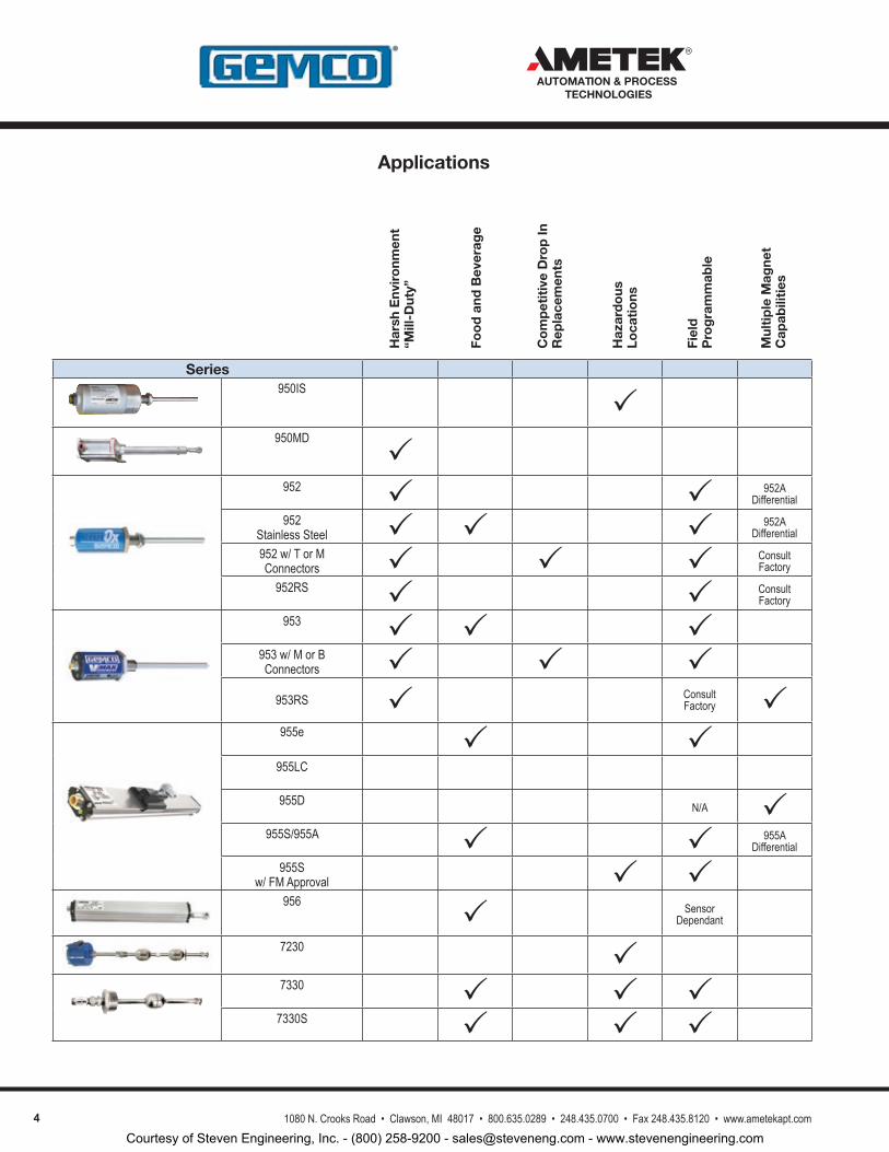
Applications
Series950IS
950MD
952 952A
Differential
952Stainless Steel 952A
Differential
952 w/ T or M Connectors Consult
Factory
952RS ConsultFactory
953 953 w/ M or B Connectors
953RS ConsultFactory
955e 955LC
955D N/A 955S/955A 955A
Differential
955S w/ FM Approval
956 Sensor
Dependant
7230 7330
7330S
Har
sh E
nvir
onm
ent
“M
ill-D
uty”
Foo
d a
nd B
ever
age
Co
mp
etit
ive
Dro
p In
R
epla
cem
ents
Haz
ard
ous
Lo
cati
ons
Fiel
d
Pro
gra
mm
able
Mul
tip
le M
agne
t
Cap
abili
ties
Courtesy of Steven Engineering, Inc. - (800) 258-9200 - [email protected] - www.stevenengineering.com
51080 N. Crooks Road • Clawson, MI 48017 • 800.635.0289 • 248.435.0700 • Fax 248.435.8120 • www.ametekapt.com
AUTOMATION & PROCESS TECHNOLOGIES
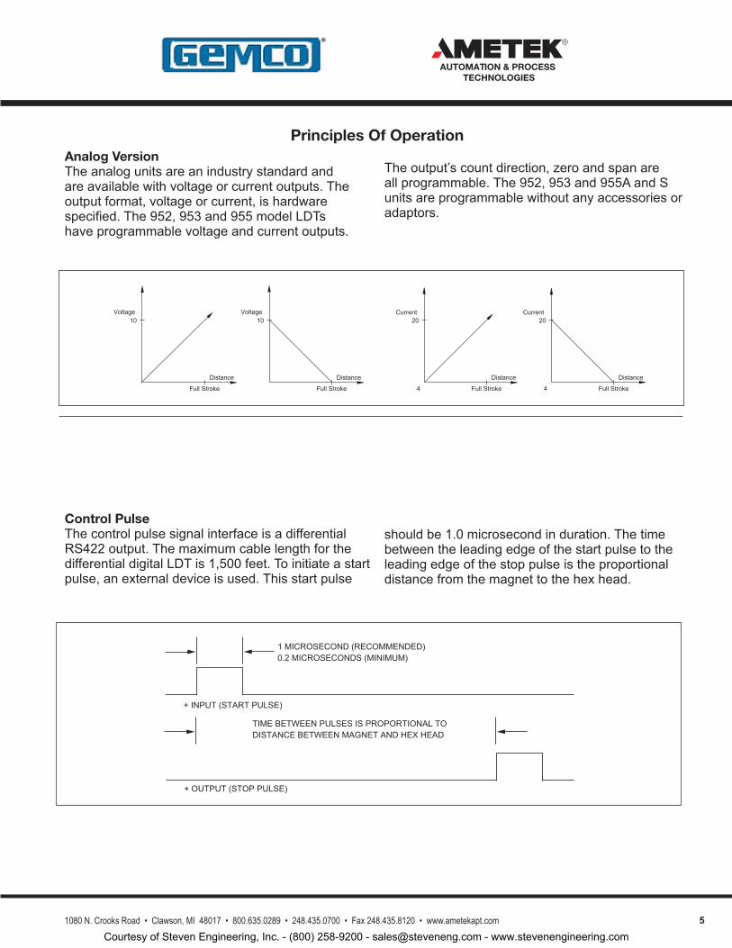
Analog VersionTheanalogunitsareanindustrystandardandareavailablewithvoltageorcurrentoutputs.Theoutputformat,voltageorcurrent,ishardwarespecified.The952,953and955modelLDTshaveprogrammablevoltageandcurrentoutputs.
Theoutput’scountdirection,zeroandspanareallprogrammable.The952,953and955AandSunitsareprogrammablewithoutanyaccessoriesoradaptors.
1MICROSECOND(RECOMMENDED)0.2MICROSECONDS(MINIMUM)
+INPUT(STARTPULSE)
TIMEBETWEENPULSESISPROPORTIONALTODISTANCEBETWEENMAGNETANDHEXHEAD
+OUTPUT(STOPPULSE)
Control PulseThecontrolpulsesignalinterfaceisadifferentialRS422output.ThemaximumcablelengthforthedifferentialdigitalLDTis1,500feet.Toinitiateastartpulse,anexternaldeviceisused.Thisstartpulse
shouldbe1.0microsecondinduration.Thetimebetweentheleadingedgeofthestartpulsetotheleadingedgeofthestoppulseistheproportionaldistancefromthemagnettothehexhead.
10
FullStroke
Distance
Voltage
Distance
FullStroke
Voltage10
4
Distance
FullStroke 4
Current20 20
Current
FullStroke
Distance
Principles Of Operation
Courtesy of Steven Engineering, Inc. - (800) 258-9200 - [email protected] - www.stevenengineering.com
6 1080 N. Crooks Road • Clawson, MI 48017 • 800.635.0289 • 248.435.0700 • Fax 248.435.8120 • www.ametekapt.com
AUTOMATION & PROCESS TECHNOLOGIES
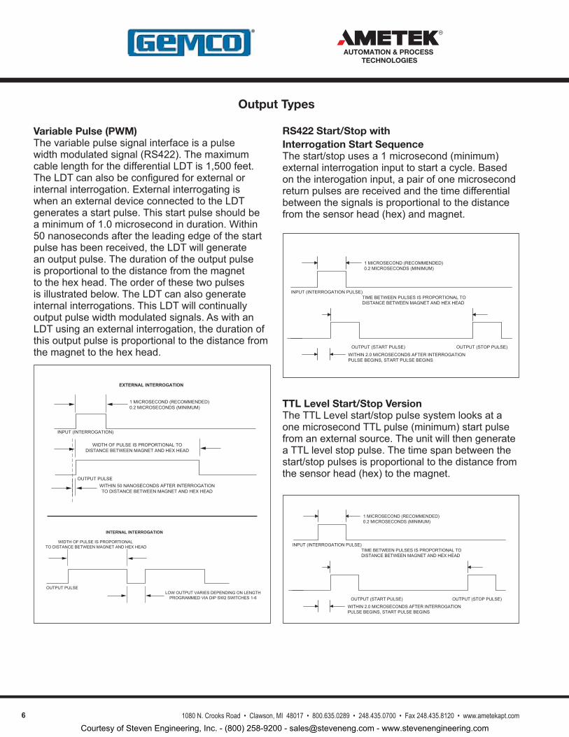
Variable Pulse (PWM)Thevariablepulsesignalinterfaceisapulsewidthmodulatedsignal(RS422).ThemaximumcablelengthforthedifferentialLDTis1,500feet.TheLDTcanalsobeconfiguredforexternalorinternalinterrogation.ExternalinterrogatingiswhenanexternaldeviceconnectedtotheLDTgeneratesastartpulse.Thisstartpulseshouldbeaminimumof1.0microsecondinduration.Within50nanosecondsaftertheleadingedgeofthestartpulsehasbeenreceived,theLDTwillgenerateanoutputpulse.Thedurationoftheoutputpulseisproportionaltothedistancefromthemagnettothehexhead.Theorderofthesetwopulsesisillustratedbelow.TheLDTcanalsogenerateinternalinterrogations.ThisLDTwillcontinuallyoutputpulsewidthmodulatedsignals.AswithanLDTusinganexternalinterrogation,thedurationofthisoutputpulseisproportionaltothedistancefromthemagnettothehexhead.
OUTPUTPULSELOWOUTPUTVARIESDEPENDINGONLENGTHPROGRAMMEDVIADIPSW2SWITCHES1-6
WIDTHOFPULSEISPROPORTIONALTODISTANCEBETWEENMAGNETANDHEXHEAD
INTERNAL INTERROGATION
INPUT(INTERROGATION)
1MICROSECOND(RECOMMENDED)0.2MICROSECONDS(MINIMUM)
WIDTHOFPULSEISPROPORTIONALTODISTANCEBETWEENMAGNETANDHEXHEAD
OUTPUTPULSEWITHIN50NANOSECONDSAFTERINTERROGATIONTODISTANCEBETWEENMAGNETANDHEXHEAD
EXTERNAL INTERROGATION
RS422 Start/Stop with Interrogation Start SequenceThestart/stopusesa1microsecond(minimum)externalinterrogationinputtostartacycle.Basedontheinterogationinput,apairofonemicrosecondreturnpulsesarereceivedandthetimedifferentialbetweenthesignalsisproportionaltothedistancefromthesensorhead(hex)andmagnet.
TTL Level Start/Stop VersionTheTTLLevelstart/stoppulsesystemlooksataonemicrosecondTTLpulse(minimum)startpulsefromanexternalsource.TheunitwillthengenerateaTTLlevelstoppulse.Thetimespanbetweenthestart/stoppulsesisproportionaltothedistancefromthesensorhead(hex)tothemagnet.
INPUT(INTERROGATIONPULSE)
1MICROSECOND(RECOMMENDED)0.2MICROSECONDS(MINIMUM)
TIMEBETWEENPULSESISPROPORTIONALTODISTANCEBETWEENMAGNETANDHEXHEAD
OUTPUT(STARTPULSE) OUTPUT(STOPPULSE)
WITHIN2.0MICROSECONDSAFTERINTERROGATIONPULSEBEGINS,STARTPULSEBEGINS
INPUT(INTERROGATIONPULSE)
1MICROSECOND(RECOMMENDED)0.2MICROSECONDS(MINIMUM)
TIMEBETWEENPULSESISPROPORTIONALTODISTANCEBETWEENMAGNETANDHEXHEAD
OUTPUT(STARTPULSE) OUTPUT(STOPPULSE)
WITHIN2.0MICROSECONDSAFTERINTERROGATIONPULSEBEGINS,STARTPULSEBEGINS
Output Types
Courtesy of Steven Engineering, Inc. - (800) 258-9200 - [email protected] - www.stevenengineering.com
71080 N. Crooks Road • Clawson, MI 48017 • 800.635.0289 • 248.435.0700 • Fax 248.435.8120 • www.ametekapt.com
AUTOMATION & PROCESS TECHNOLOGIES
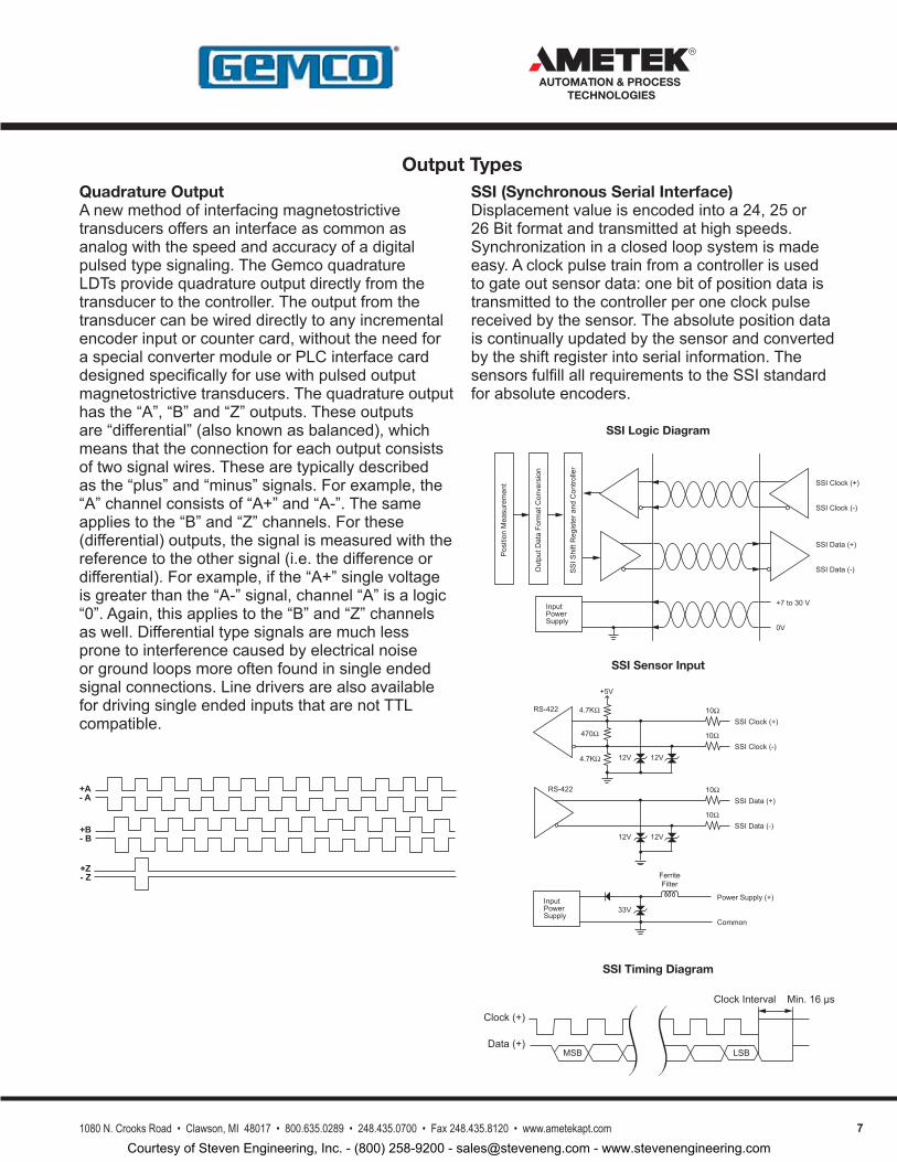
Quadrature OutputAnewmethodofinterfacingmagnetostrictivetransducersoffersaninterfaceascommonasanalogwiththespeedandaccuracyofadigitalpulsedtypesignaling.TheGemcoquadratureLDTsprovidequadratureoutputdirectlyfromthetransducertothecontroller.Theoutputfromthetransducercanbewireddirectlytoanyincrementalencoderinputorcountercard,withouttheneedforaspecialconvertermoduleorPLCinterfacecarddesignedspecificallyforusewithpulsedoutputmagnetostrictivetransducers.Thequadratureoutputhasthe“A”,“B”and“Z”outputs.Theseoutputsare“differential”(alsoknownasbalanced),whichmeansthattheconnectionforeachoutputconsistsoftwosignalwires.Thesearetypicallydescribedasthe“plus”and“minus”signals.Forexample,the“A”channelconsistsof“A+”and“A-”.Thesameappliestothe“B”and“Z”channels.Forthese(differential)outputs,thesignalismeasuredwiththereferencetotheothersignal(i.e.thedifferenceordifferential).Forexample,ifthe“A+”singlevoltageisgreaterthanthe“A-”signal,channel“A”isalogic“0”.Again,thisappliestothe“B”and“Z”channelsaswell.Differentialtypesignalsaremuchlesspronetointerferencecausedbyelectricalnoiseorgroundloopsmoreoftenfoundinsingleendedsignalconnections.LinedriversarealsoavailablefordrivingsingleendedinputsthatarenotTTLcompatible.
SSI (Synchronous Serial Interface)Displacementvalueisencodedintoa24,25or26Bitformatandtransmittedathighspeeds.Synchronizationinaclosedloopsystemismadeeasy.Aclockpulsetrainfromacontrollerisusedtogateoutsensordata:onebitofpositiondataistransmittedtothecontrollerperoneclockpulsereceivedbythesensor.Theabsolutepositiondataiscontinuallyupdatedbythesensorandconvertedbytheshiftregisterintoserialinformation.ThesensorsfulfillallrequirementstotheSSIstandardforabsoluteencoders.
SSI Clock (+)
SSI Clock (-)
SSI Data (+)
SSI Data (-)
+7 to 30 V
0V
Input Power Supply
SS
I Shi
ft R
egis
ter a
nd C
ontro
ller
Out
put D
ata
Form
at C
onve
rsio
n
Pos
ition
Mea
sure
men
t
SSI Clock (+)
SSI Clock (-)
4.7KΩ
470Ω
4.7KΩ 12V 12V
10Ω
10Ω
SSI Data (+)
SSI Data (-)12V 12V
10Ω
10Ω
Power Supply (+)
Common
33VInput Power Supply
Ferrite Filter
+5V
RS-422
RS-422
SSI Logic Diagram
SSI Sensor Input
SSI Timing Diagram
Clock (+)
Data (+)
Clock Interval
LSBMSB
Min. 16 µs
+A- A
+B- B
+Z- Z
Output Types
Courtesy of Steven Engineering, Inc. - (800) 258-9200 - [email protected] - www.stevenengineering.com
8 1080 N. Crooks Road • Clawson, MI 48017 • 800.635.0289 • 248.435.0700 • Fax 248.435.8120 • www.ametekapt.com
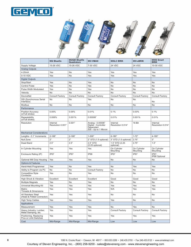
952 BlueOx 952QD BlueOx Quadrature 953 VMAX 955LC BRIK 955 eBRIK 955S Smart
BRIKSupplyVoltage 15-26VDC 15-26VDC 7-30VDC 24VDC 24VDC 10-30VDCAnalogOutputs4-20mA Yes No Yes Yes Yes Yes0-10VDC Yes No Yes Yes Yes YesDigitalOutputsStop/Start Yes No Yes No No NoControlPulse Yes No Yes No No NoPulseWidthModulated Yes No Yes No No NoVelocity No No No No No NoDeviceNet ConsultFactory ConsultFactory ConsultFactory ConsultFactory ConsultFactory ConsultFactorySSI(SynchronousSerialInterface)
No No Yes No NoNo
Modbus No No No No No NoPerformancePositionAccuracy(offullstroke)
0.05% 0.05% 0.01% 0.1% 0.03% 0.1%
Repeatability(offullstroke)
0.006% 0.001% 0.00006” 0.01% 0.001% 0.01%
Resolution InternalResolution0.001”
0.001” Analog-0.00006”Digital-ControllerDependantSSI-Upto1Micron
InternalResolution0.014”
16-Bit InternalResolution0.014”
MechanicalConsiderationsLengths-0.1”Increments 2-168” 2-168” 1-300” 6-180” 1-72” 4-180”NullZone 2” 2” 2”STD(1.5optional) 3”STD(1.5optional) 2.75” 3”DeadBand 2.5” 2.5” 2.5”STD
(2.25optional)1.5”STD(2.25optional)
2.75” 1.5”
InCylinderMounting Yes Yes Yes OnCylinderMounting
OnCylinderMounting
OnCylinderMounting
EnclosureRating(IP) IP67 IP67 IP68 IP67 IP67 IP67,IP68Optional
OptionalMillDutyHousing Yes Yes Yes No No NoOptions&FeaturesHand-HeldProgrammer Yes No Yes No Yes YesAbilitytoProgramviaPC No No ConsultFactory No No NoCompetitiveStyleConnector
Yes No Yes No No No
HighShock&Vibration Excellent Excellent Excellent Good Good GoodMultipleMagnets Yes No Yes No No NoUniversalMountingKit Yes Yes Yes Yes Yes YesMetricThreads&Dimensions
Yes Yes Yes N/A Yes Yes
AllStainlessSteel(Head&PottedConnector)
Yes Yes Yes No No No
HighTempCables Yes Yes Yes Yes No NoApplicationsMeasurement Yes Yes Yes No Yes NoHeavyIndustry,Lumber,MetalStamping,etc.
Yes Yes Yes ConsultFactory ConsultFactory ConsultFactory
Positioning,ReplacingProxorLimitSwitches
Yes Yes Yes Yes Yes Yes
Cost Mid-Range Mid-Range Mid-Range Low Low Low
Courtesy of Steven Engineering, Inc. - (800) 258-9200 - [email protected] - www.stevenengineering.com
91080 N. Crooks Road • Clawson, MI 48017 • 800.635.0289 • 248.435.0700 • Fax 248.435.8120 • www.ametekapt.com
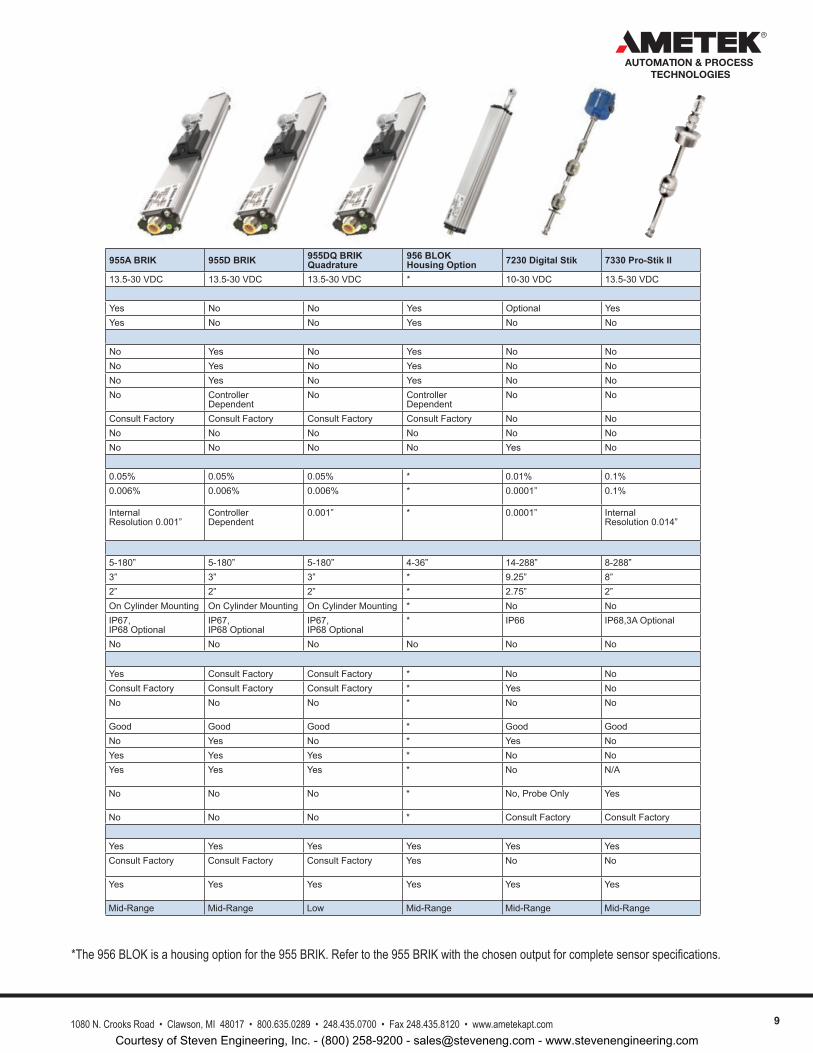
*The 956 BLOK is a housing option for the 955 BRIK. Refer to the 955 BRIK with the chosen output for complete sensor specifications.
955A BRIK 955D BRIK 955DQ BRIK Quadrature
956 BLOKHousing Option 7230 Digital Stik 7330 Pro-Stik II
13.5-30VDC 13.5-30VDC 13.5-30VDC * 10-30VDC 13.5-30VDC
Yes No No Yes Optional YesYes No No Yes No No
No Yes No Yes No NoNo Yes No Yes No NoNo Yes No Yes No NoNo Controller
DependentNo Controller
DependentNo No
ConsultFactory ConsultFactory ConsultFactory ConsultFactory No NoNo No No No No NoNo No No No Yes No
0.05% 0.05% 0.05% * 0.01% 0.1%0.006% 0.006% 0.006% * 0.0001” 0.1%
InternalResolution0.001”
ControllerDependent
0.001” * 0.0001” InternalResolution0.014”
5-180” 5-180” 5-180” 4-36” 14-288” 8-288”3” 3” 3” * 9.25” 8”2” 2” 2” * 2.75” 2”OnCylinderMounting OnCylinderMounting OnCylinderMounting * No NoIP67,IP68Optional
IP67,IP68Optional
IP67,IP68Optional
* IP66 IP68,3AOptional
No No No No No No
Yes ConsultFactory ConsultFactory * No NoConsultFactory ConsultFactory ConsultFactory * Yes NoNo No No * No No
Good Good Good * Good GoodNo Yes No * Yes NoYes Yes Yes * No NoYes Yes Yes * No N/A
No No No * No,ProbeOnly Yes
No No No * ConsultFactory ConsultFactory
Yes Yes Yes Yes Yes YesConsultFactory ConsultFactory ConsultFactory Yes No No
Yes Yes Yes Yes Yes Yes
Mid-Range Mid-Range Low Mid-Range Mid-Range Mid-Range
AUTOMATION & PROCESS TECHNOLOGIES
Courtesy of Steven Engineering, Inc. - (800) 258-9200 - [email protected] - www.stevenengineering.com
10 1080 N. Crooks Road • Clawson, MI 48017 • 800.635.0289 • 248.435.0700 • Fax 248.435.8120 • www.ametekapt.com
AUTOMATION & PROCESS TECHNOLOGIES
950I
S
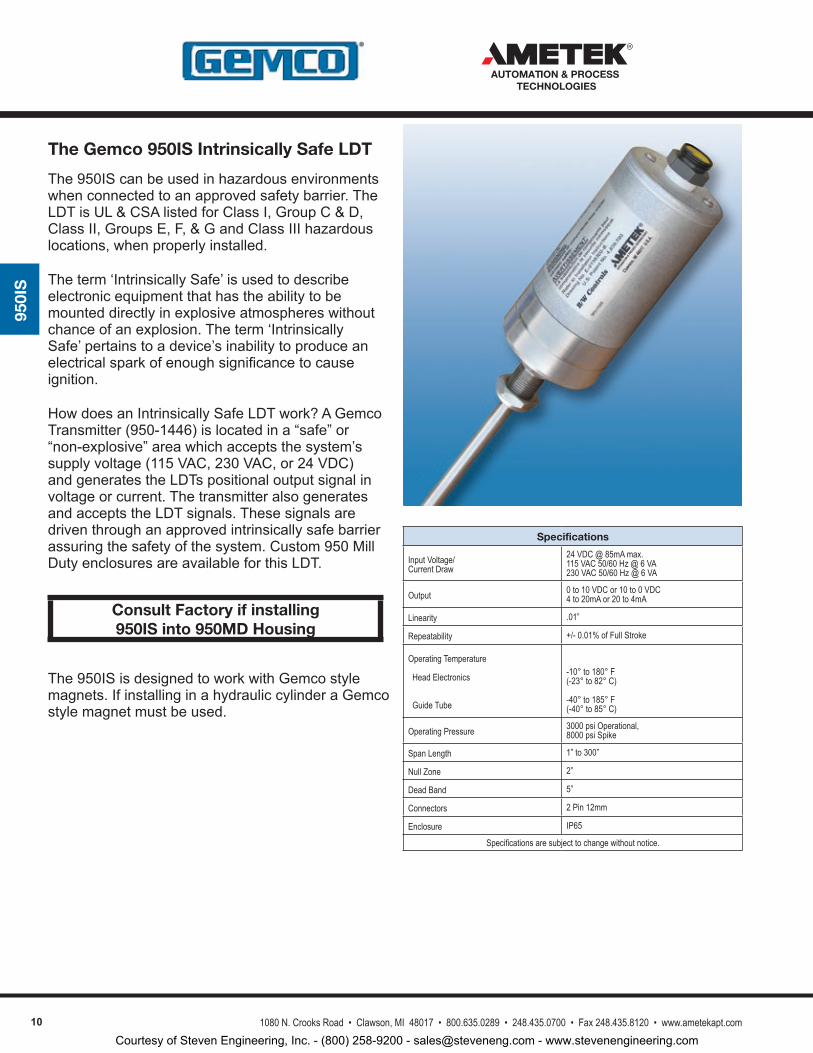
The950IScanbeusedinhazardousenvironmentswhenconnectedtoanapprovedsafetybarrier.TheLDTisUL&CSAlistedforClassI,GroupC&D,ClassII,GroupsE,F,&GandClassIIIhazardouslocations,whenproperlyinstalled.
Theterm‘IntrinsicallySafe’isusedtodescribeelectronicequipmentthathastheabilitytobemounteddirectlyinexplosiveatmosphereswithoutchanceofanexplosion.Theterm‘IntrinsicallySafe’pertainstoadevice’sinabilitytoproduceanelectricalsparkofenoughsignificancetocauseignition.
HowdoesanIntrinsicallySafeLDTwork?AGemcoTransmitter(950-1446)islocatedina“safe”or“non-explosive”areawhichacceptsthesystem’ssupplyvoltage(115VAC,230VAC,or24VDC)andgeneratestheLDTspositionaloutputsignalinvoltageorcurrent.ThetransmitteralsogeneratesandacceptstheLDTsignals.Thesesignalsaredriventhroughanapprovedintrinsicallysafebarrierassuringthesafetyofthesystem.Custom950MillDutyenclosuresareavailableforthisLDT.
The950ISisdesignedtoworkwithGemcostylemagnets.IfinstallinginahydrauliccylinderaGemcostylemagnetmustbeused.
Specifications
Input Voltage/Current Draw
24 VDC @ 85mA max.115 VAC 50/60 Hz @ 6 VA230 VAC 50/60 Hz @ 6 VA
Output 0 to 10 VDC or 10 to 0 VDC4 to 20mA or 20 to 4mA
Linearity .01”
Repeatability +/- 0.01% of Full Stroke
Operating Temperature
Head Electronics
Guide Tube
-10° to 180° F (-23° to 82° C)
-40° to 185° F (-40° to 85° C)
Operating Pressure 3000 psi Operational, 8000 psi Spike
Span Length 1” to 300”
Null Zone 2”
Dead Band 5”
Connectors 2 Pin 12mm
Enclosure IP65
Specifications are subject to change without notice.
Consult Factory if installing 950IS into 950MD Housing
The Gemco 950IS Intrinsically Safe LDT
Courtesy of Steven Engineering, Inc. - (800) 258-9200 - [email protected] - www.stevenengineering.com
111080 N. Crooks Road • Clawson, MI 48017 • 800.635.0289 • 248.435.0700 • Fax 248.435.8120 • www.ametekapt.com
AUTOMATION & PROCESS TECHNOLOGIES
950I
S
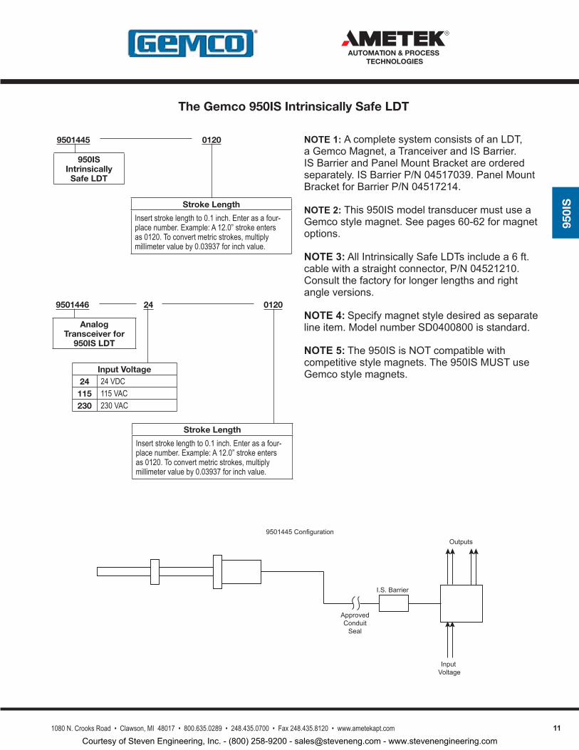
NOTE 1:AcompletesystemconsistsofanLDT,aGemcoMagnet,aTranceiverandISBarrier.ISBarrierandPanelMountBracketareorderedseparately.ISBarrierP/N04517039.PanelMountBracketforBarrierP/N04517214.
NOTE 2:This950ISmodeltransducermustuseaGemcostylemagnet.Seepages60-62formagnetoptions.
NOTE 3:AllIntrinsicallySafeLDTsincludea6ft.cablewithastraightconnector,P/N04521210.Consultthefactoryforlongerlengthsandrightangleversions.
NOTE 4: Specifymagnetstyledesiredasseparatelineitem.ModelnumberSD0400800isstandard.
NOTE 5: The950ISisNOTcompatiblewithcompetitivestylemagnets.The950ISMUSTuseGemcostylemagnets.
9501446 012024
Input Voltage24 24 VDC115 115 VAC230 230 VAC
Analog Transceiver for
950IS LDT
Stroke Length
Insert stroke length to 0.1 inch. Enter as a four-place number. Example: A 12.0” stroke enters as 0120. To convert metric strokes, multiply millimeter value by 0.03937 for inch value.
9501445 0120
950IS Intrinsically Safe LDT
Stroke Length
Insert stroke length to 0.1 inch. Enter as a four-place number. Example: A 12.0” stroke enters as 0120. To convert metric strokes, multiply millimeter value by 0.03937 for inch value.
I.S.Barrier
ApprovedConduitSeal
Outputs
InputVoltage
9501445Configuration
The Gemco 950IS Intrinsically Safe LDT
Courtesy of Steven Engineering, Inc. - (800) 258-9200 - [email protected] - www.stevenengineering.com
12 1080 N. Crooks Road • Clawson, MI 48017 • 800.635.0289 • 248.435.0700 • Fax 248.435.8120 • www.ametekapt.com
AUTOMATION & PROCESS TECHNOLOGIES
950I
S
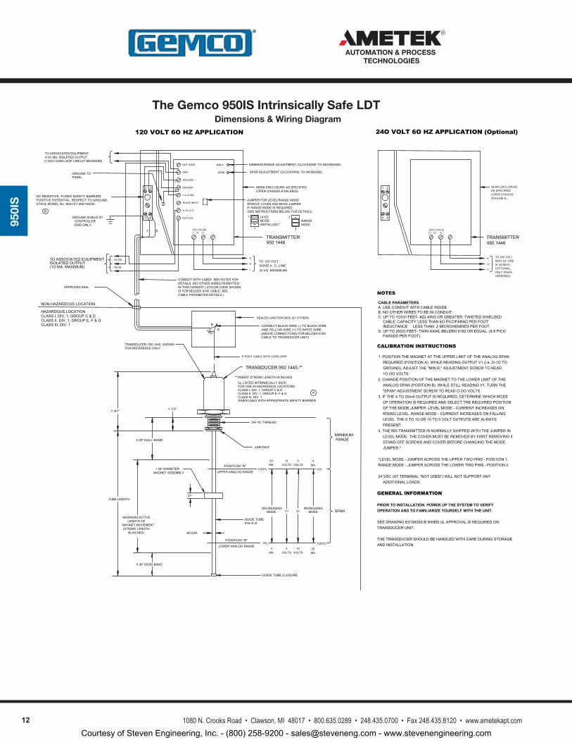
Dimensions & Wiring Diagram
131080 N. Crooks Road • Clawson, MI 48017 • 800.635.0289 • 248.435.0700 • Fax 248.435.8120 • www.ametekapt.com
950I
S
Dimensions & Wiring Diagram
950IS Intrinsically Safe
4FOOTCABLEWITHCORDGRIP
3/4-16THREAD
TRANSDUCER, 9501445,SHOWNFORREFERENCEONLY
2.00" NULLBAND
GUIDETUBE316S.S.
TUBELENGTH
CONNECTBLACKWIRE(-)TOBLACKWIREANDYELLOWWIRE(+)TOWHITEWIRE.
5.00"DEADBAND
7.81"
O%
1OO%
SPAN
1.13"
YW
BB
V1 V2INCREASING
MODE
2OMA.POSITION"A"
POSITION"B"
1OO%UPPERANALOGRANGE
O%LOWERANALOGRANGE
MAXIMUMACTIVELENGTH OF
MAGNET MOVEMENT(STROKELENGTH
MINIMUMRANGE
(ABOVECONNECTIONSFORBELDEN9182CABLETOTRANSDUCER UNIT)
SEALED JUNCTIONBOX,BYOTHERS.
NON-HAZARDOUSLOCATION
HAZARDOUSLOCATION
CLASSII,DIV.1,GROUPE,F&GCLASSIII,DIV.1
CLASSI,DIV.1,GROUPC&D
APPROVEDSEAL
10VOLTS
0VOLTS
4MA.
VOLTSMA. VOLTS4 0
MA.10 20
DECREASINGMODE
GUIDE TUBECLOSURE
JAM NUT
ININCHES)
.31"
MAGNET ASSEMBLY1.28"DIAMETER
.40DIA.
24OV6OHZL1L2 G
3
1
4
2
L1
L2
G
9501446TRANSMITTER
24O VOLT 6O HZ APPLICATION (Optional)
SPANADJUSTMENT(CLOCKWISETOINCREASE)
MINIMUMRANGEADJUSTMENT(CLOCKWISE TODECREASE)
120 VOLT 6O HZ APPLICATION
POSITIVEPOTENTIAL,RESPECT TOGROUND,STAHLMODELNo.9001/01-280/165/00.
DC-RESISTIVE,FUSEDSAFETYBARRIER,
ENDONLY.CONTROLLER
GROUNDSHIELDAT
(1OMA.MAXIMUM)
TOASSOCIATEDEQUIPMENT
(1,OOOOHMLOOPCIRCUITMAXIMUM)4-2OMA.ISOLATEDOUTPUTTOASSOCIATEDEQUIPMENT
ISOLATEDOUTPUT
PANELGROUNDTO
CONDUIT WITHCABLE.SEENOTESFOR
120V6OHZLN G
1O-O
O-1O
Y B
3 4
1 B
Y
SLAVEINPUT
O-1O(V1)
1O-O(V2)
+4-20MA
XDUCER -
XDUCER +
NOTUSED
GND
RANGE(INSTALLED) *
9501446TRANSMITTER
(6VA.MAXIMUM)6OHZA.C.LINETO120VOLT
L
N
G
1MODE
2
(SEEINSTRUCTIONSBELOWFORDETAILS)IFRANGEMODEISREQUIRED.REMOVECOVERANDMOVEJUMPERJUMPERFORLEVEL/RANGEMODE.
(OPEN CHASSISAVAILABLE)NEMAENCLOSUREASSPECIFIED
1MODELEVEL
MIN.R.
SPAN
1
CABLEPARAMETER DETAILS.)IS FOR BELDEN 9182CABLE.SEEINTHISCONDUIT.)(COLOR CODESHOWNDETAILS. (NO OTHERWIRESPERMITTED
WHENUSEDWITHAPPROPRIATESAFETYBARRIER
ULLISTEDINTRINSICALLYSAFE
CLASSIII,DIV.1CLASSII,DIV.1,GROUPE,F&GCLASSI,DIV.1,GROUPC&DFORUSEINHAZARDOUSLOCATIONS:
**INSERTSTROKELENGTHININCHES.
TRANSDUCER9501445-**
A
B
6
2
NOTES
CABLE PARAMETERSA.USECONDUITWITHCABLEINSIDE.B.NOOTHERWIRESTOBEINCONDUIT.C.UPTO1OOOFEET-#22AWGORGREATER,TWISTEDSHIELDED
CABLE,CAPACITYLESSTHAN6OPICOFARADPERFOOT,INDUCTANCELESSTHAN.2MICROHENRIESPERFOOT.
D.UPTO25OOFEET-TWINAXIALBELDEN9182OREQUAL.(8.8PICOFARADSPERFOOT).
CALIBRATION INSTRUCTIONS
1.POSITIONTHEMAGNETATTHEUPPERLIMITOFTHEANALOGSPANREQUIRED(POSITIONA).WHILEREADINGOUTPUTV1(i.e.O-1OTOGROUND),ADJUSTTHE"MIN.R."ADJUSTMENTSCREWTOREAD1O.OOVOLTS.
2.CHANGEPOSITIONOFTHEMAGNETTOTHELOWERLIMITOFTHEANALOGSPAN(POSITIONB).WHILESTILLREADINGV1,TURNTHE"SPAN"ADJUSTMENTSCREWTOREADO.OOVOLTS.
3.IFTHE4TO20mAOUTPUTISREQUIRED,DETERMINEWHICHMODEOFOPERATIONISREQUIREDANDSELECTTHEREQUIREDPOSITIONOFTHEMODEJUMPER.LEVELMODE-CURRENTINCREASESONRISINGLEVEL.RANGEMODE-CURRENTINCREASESONFALLINGLEVEL.THE0TO10OR10TO0VOLTOUTPUTSAREALWAYSPRESENT.
4.THE950TRANSMITTERISNORMALLYSHIPPEDWITHTHEJUMPERINLEVELMODE.THECOVERMUSTBEREMOVEDBYFIRSTREMOVING4STAND-OFFSCREWSANDCOVERBEFORECHANGINGTHEMODEJUMPER.*
*LEVELMODE-JUMPERACROSSTHEUPPERTWOPINS-POSITION1.RANGEMODE-JUMPERACROSSTHELOWERTWOPINS-POSITION2.
24VDC(ATTERMINAL“NOTUSED”)WILLNOTSUPPORTANYADDITIONALLOADS.
GENERAL INFORMATION
PRIOR TO INSTALLATION, POWER UP THE SYSTEM TO VERIFY OPERATION AND TO FAMILIARIZE YOURSELF WITH THE UNIT.
SEEDRAWINGE0198300-BWHENULAPPROVALISREQUIREDONTRANSDUCERUNIT.
THETRANSDUCERSHOULDBEHANDLEDWITHCAREDURINGSTORAGEANDINSTALLATION.
TO240VOLT60HZACLINE(6VAMAX)(OPTIONAL,ONLYWHENORDERED)
NEMAENCLOSUREASSPECIFIED(OPENCHASSISAVAILABLE)
The Gemco 950IS Intrinsically Safe LDT
Courtesy of Steven Engineering, Inc. - (800) 258-9200 - [email protected] - www.stevenengineering.com
131080 N. Crooks Road • Clawson, MI 48017 • 800.635.0289 • 248.435.0700 • Fax 248.435.8120 • www.ametekapt.com
AUTOMATION & PROCESS TECHNOLOGIES
950M
D
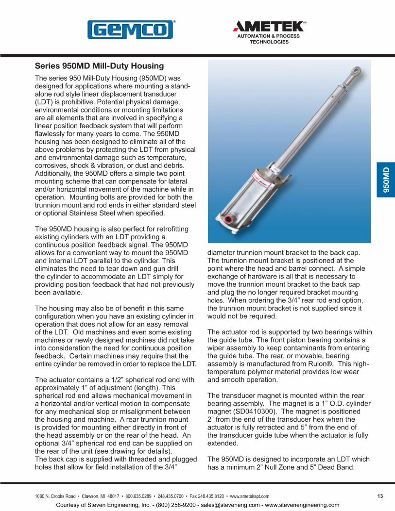
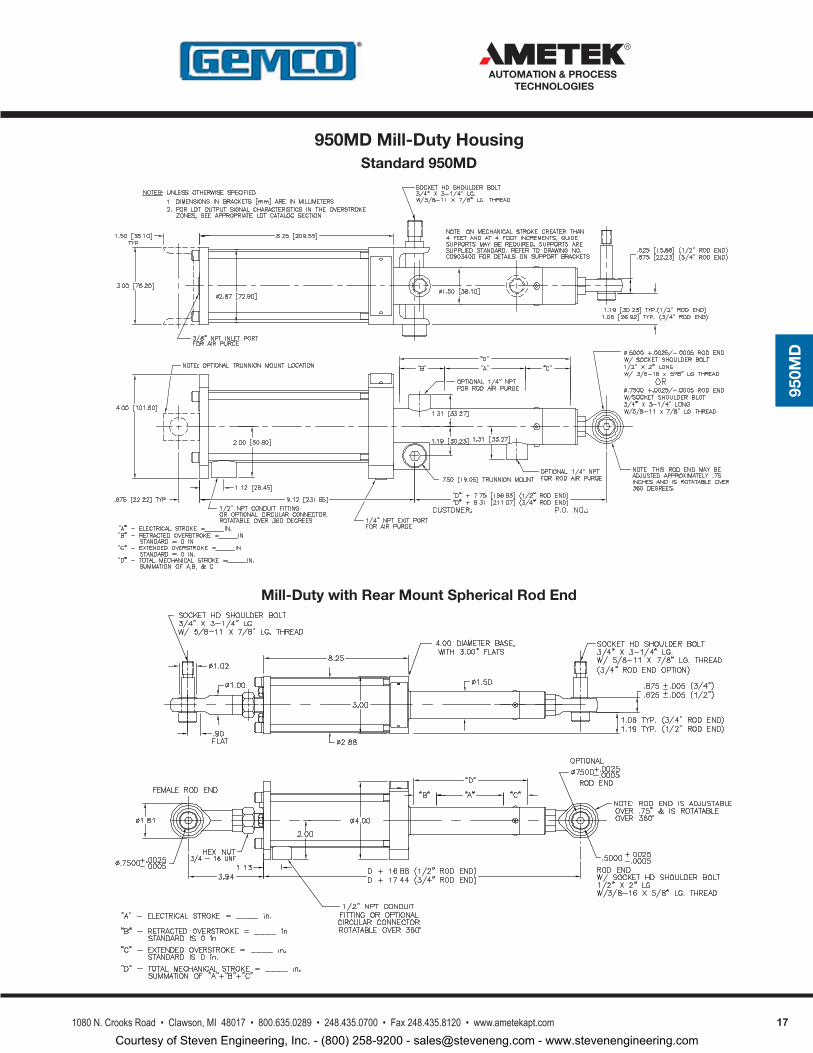
Theseries950Mill-DutyHousing(950MD)wasdesignedforapplicationswheremountingastand-alonerodstylelineardisplacementtransducer(LDT)isprohibitive.Potentialphysicaldamage,environmentalconditionsormountinglimitationsareallelementsthatareinvolvedinspecifyingalinearpositionfeedbacksystemthatwillperformflawlesslyformanyyearstocome.The950MDhousinghasbeendesignedtoeliminatealloftheaboveproblemsbyprotectingtheLDTfromphysicalandenvironmentaldamagesuchastemperature,corrosives,shock&vibration,ordustanddebris.Additionally,the950MDoffersasimpletwopointmountingschemethatcancompensateforlateraland/orhorizontalmovementofthemachinewhileinoperation.MountingboltsareprovidedforboththetrunnionmountandrodendsineitherstandardsteeloroptionalStainlessSteelwhenspecified.
The950MDhousingisalsoperfectforretrofittingexistingcylinderswithanLDTprovidingacontinuouspositionfeedbacksignal.The950MDallowsforaconvenientwaytomountthe950MDandinternalLDTparalleltothecylinder.ThiseliminatestheneedtoteardownandgundrillthecylindertoaccommodateanLDTsimplyforprovidingpositionfeedbackthathadnotpreviouslybeenavailable.
ThehousingmayalsobeofbenefitinthissameconfigurationwhenyouhaveanexistingcylinderinoperationthatdoesnotallowforaneasyremovaloftheLDT.Oldmachinesandevensomeexistingmachinesornewlydesignedmachinesdidnottakeintoconsiderationtheneedforcontinuouspositionfeedback.CertainmachinesmayrequirethattheentirecylinderberemovedinordertoreplacetheLDT.
Theactuatorcontainsa1/2”sphericalrodendwithapproximately1”ofadjustment(length).Thissphericalrodendallowsmechanicalmovementinahorizontaland/orverticalmotiontocompensateforanymechanicalslopormisalignmentbetweenthehousingandmachine.Areartrunnionmountisprovidedformountingeitherdirectlyinfrontoftheheadassemblyorontherearofthehead.Anoptional3/4”sphericalrodendcanbesuppliedontherearoftheunit(seedrawingfordetails).Thebackcapissuppliedwiththreadedandpluggedholesthatallowforfieldinstallationofthe3/4”
diametertrunnionmountbrackettothebackcap.Thetrunnionmountbracketispositionedatthepointwheretheheadandbarrelconnect.Asimpleexchangeofhardwareisallthatisnecessarytomovethetrunnionmountbrackettothebackcapandplugthenolongerrequiredbracketmountingholes.Whenorderingthe3/4”rearrodendoption,thetrunnionmountbracketisnotsuppliedsinceitwouldnotberequired.
Theactuatorrodissupportedbytwobearingswithintheguidetube.Thefrontpistonbearingcontainsawiperassemblytokeepcontaminantsfromenteringtheguidetube.Therear,ormovable,bearingassemblyismanufacturedfromRulon®.Thishigh-temperaturepolymermaterialprovideslowwearandsmoothoperation.
Thetransducermagnetismountedwithintherearbearingassembly.Themagnetisa1”O.D.cylindermagnet(SD0410300).Themagnetispositioned2”fromtheendofthetransducerhexwhentheactuatorisfullyretractedand5”fromtheendofthetransducerguidetubewhentheactuatorisfullyextended.
The950MDisdesignedtoincorporateanLDTwhichhasaminimum2”NullZoneand5”DeadBand.
Series 950MD Mill-Duty Housing
Courtesy of Steven Engineering, Inc. - (800) 258-9200 - [email protected] - www.stevenengineering.com
14 1080 N. Crooks Road • Clawson, MI 48017 • 800.635.0289 • 248.435.0700 • Fax 248.435.8120 • www.ametekapt.com
AUTOMATION & PROCESS TECHNOLOGIES
950M
D
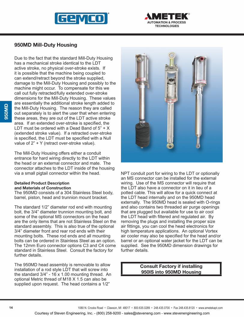
NPTconduitportforwiringtotheLDToroptionallyanMSconnectorcanbeinstalledfortheexternalwiring.UseoftheMSconnectorwillrequirethattheLDTalsohaveaconnectoronitinlieuofapottedcable.ThiswillallowforaquickconnectattheLDTheadinternallyandonthe950MDheadexternally.The950MDheadissealedwithO-ringsandalsocontainstwothreadedairpurgeopeningsthatarepluggedbutavailableforusetoaircooltheLDTheadwithfilteredandregulatedair.Byremovingtheplugsandinstallingthepropersizeairfittings,youcancooltheheadelectronicsforhightemperatureapplications.AnoptionalVortexaircoolermayalsobespecifiedfortheheadand/orbarreloranoptionalwaterjacketfortheLDTcanbesupplied.Seethe950MDdimensiondrawingsforfurtherdetails.
950MD Mill-Duty Housing
Optional Water-Cooled Head Assembly
Consult Factory if installing 950IS into 950MD Housing
Optional Bellows Boot
Optional Stainless Boot
DuetothefactthatthestandardMill-DutyHousinghasamechanicalstrokeidenticaltotheLDTactivestroke,nophysicalover-strokeexists.Ifitispossiblethatthemachinebeingcoupledtocanextend/retractbeyondthestrokesupplied,damagetotheMill-DutyHousingandpossiblytothemachinemightoccur.Tocompensateforthiswecalloutfullyretracted/fullyextendedover-strokedimensionsfortheMill-DutyHousing.ThesevaluesareessentiallytheadditionalstrokelengthaddedtotheMill-DutyHousing.Thereasontheyarecalledoutseparatelyistoalerttheuserthatwhenenteringtheseareas,theyareoutoftheLDTactivestrokearea.Ifanextendedover-strokeisspecified,theLDTmustbeorderedwithaDeadBandof5”+X(extendedstrokevalue).Ifaretractedover-strokeisspecified,theLDTmustbespecifiedwithaNullvalueof2”+Y(retractover-strokevalue).
TheMill-DutyHousingofferseitheraconduitentranceforhardwiringdirectlytotheLDTwithintheheadoranexternalconnectorandmate.TheconnectorattachestotheLDTinsideofthehousingviaasmallpigtailconnectorwithinthehead.
Detailed Product Description and Materials of ConstructionThe950MDconsistsofa304StainlessSteelbody,barrel,piston,headandtrunnionmountbracket.
Thestandard1/2”diameterrodendwithmountingbolt,the3/4”diametertrunnionmountingbolt,andsomeoftheoptionalMSconnectorsontheheadaretheonlyitemsthatarenotStainlessSteelonthestandardassembly.Thisisalsotrueoftheoptional3/4”diameterfrontandrearrodendswiththeirmountingbolts.TheserodendsandallmountingboltscanbeorderedinStainlessSteelasanoption.The12mmEuroconnectoroptionsC3andC4comestandardinStainlessSteel.Consultthefactoryforfurtherdetails.
The950MDheadassemblyisremovabletoallowinstallationofarodstyleLDTthatwillscrewintothestandard3/4”-16x1.00mountingthread.AnoptionalMetricthreadofM18X1.5canalsobesupplieduponrequest.Theheadcontainsa1/2”
Courtesy of Steven Engineering, Inc. - (800) 258-9200 - [email protected] - www.stevenengineering.com
151080 N. Crooks Road • Clawson, MI 48017 • 800.635.0289 • 248.435.0700 • Fax 248.435.8120 • www.ametekapt.com
AUTOMATION & PROCESS TECHNOLOGIES
950M
D
ApplicationsThe950MDwasoriginallydesignedforuseinsteelmillapplicationsbuthasproventobereliableinmanyapplicationswhereruggedness,environmentalprotectionandeaseofmountingarerequired.Someoftheseapplicationsinclude:
Steel Mills-Tundishcar(Tundishheight),turretheight(Caster),hydrauliccoilcars,torchcutoffmachine(torchheadmonitoring),furnacetilt,electrodepositioning,sideguidepositioning,ladleslidegatepositioning,louverorroofposition,etc.
Foundries, Forging and Casting–Lineartransducerswith950MDhousingshavebeenusedonsandmoldcompactors,furnaceorovendoorsandmaterialtransfersystems.
Injection Molding and Die Casting–Proveneffectiveinmonitoring/controllingthepositionoftheclampand/orshotcylinder.Thetwopointconnectionofthe950MDhousingallowsforasimpleretrofitbyreplacinglimitswitcheswithanLDTforpositionfeedbackovertheentirerangemovement.Linearpotentiometerscanalsobereplaced,thuseliminatingtheirproblemswithdrift,temperature,andshortlifespan.
Hydraulic Servo Applications-Idealforinstallingparalleltohydrauliccylindersincludingnewapplicationsandretrofits.Themajoradvantagetousingthe950MDhousingversusgundrillingthecylinderforanLDTisthatthecylinderfluidflowisnotcompromised.IfanLDTfailswithinacylinderitcannotberemovedwithouthavingtodealwiththehydraulicfluidlines,pressureetc.Somecylindersmaybedifficulttoremoveonceinstalled,thusinhibitingtheremovaloftheLDT.The950MDhousingistypicallymountedparalleltothecylinder,thesameasaslavecylinderwouldbe,soremovalisgreatlysimplifiedundertheseconditions.
Lock and Dam Sites-MitergateandTaintervalvepositionfeedbacksystemshavebothbenefitedfromthe950MDandLDTcombination.
Gate Position Feedback-Forhydro-electricplants,watercontrolstructures,waterandwastewatertreatmentandmanaging,wickettgatepositionfeedbackforTurbinespeedcontrol.
Optional ItemsThestandardMill-DutyHousingincludesthecomplete
housingassemblywithprovisionstoacceptanLDTandallbolts,nutsandmountinghardwarerequiredforacompleteinstallation.Therearealsoseveraloptionalitemsavailable.
Vortex Air Cooler-Thestandard950MDisequippedwithairpurgeports.Inmanycases,runningcleanshopairthroughtheheadissufficienttocooltheelectronics.ForseveretemperatureapplicationsaVortexAirCoolermaybedesired.AVortexAirCooleracceptsstandardshopair(80-100PSIG).TheairisejectedthroughageneratorinaVortexspinchamberwheretheairstreamrevolvesinatubeatupto1,000,000RPM.Insimplesttermstheinnerstreamgivesoffenergyintheformofheattotheouterstreamandtheinnerstreamexitstheoppositeendashotair.TheVortexCooleriscapableofgeneratingairflowsascoldas-40°F.
Protective Boots -Togiveaddedprotectiontotheactuatorrod,protectivebootsareavailable.ThesebootsattachbetweentheendoftheMill-Dutyguidetubeandtheendoftheactuatorrodassembly.Thebootsareofferedinneoprenecoatednylonformoststandardapplications.Theyoffer-60°Fto250°Foperatingrangewithresistancetowaterandoil.Also,siliconecoatedfiberglassoffershightemperatureresistancefrom-100°Fto550°F;Teflon-coatedfiberglassoffers-100°Fto500°Foperatingrangewithahighdegreeofcorrosionresistanceandoptionalstainlesssteelbootsforruggedapplications.
Water-Cooled Head Assemblies-Inapplicationswhereextremetemperaturesarepresentandaircoolingisnotappropriate,water-cooledheadassembliesareavailable.Coolingjacketswithintheheadassemblyallowwatertoflowaroundtheelectronics.
Front and Rear Mount Spherical Rod Ends-Inapplicationswheretwosphericalrodendsarerequired,rearmountsphericalrodendsareavailable.The3/4”rearrodendattachestoathreadedboltextendingfromtherearofthehead.The3/4”frontrodendisthreadedintothepistonrod.Anoptionalstainlesssteelversionisavailable.Mountingboltsaresuppliedwithbothversions.
Delrin Liner -Usedinlongerhorizontalapplications,typically60”orlongertopreventwearontheLDT’sguidetubeasthe950MDhousingisstroked.TheDelrinlinerisinstalledinsideofthe950MDbarrelandpreventssagoftheLDT’sguidetube.
950MD Mill-Duty Housing
Courtesy of Steven Engineering, Inc. - (800) 258-9200 - [email protected] - www.stevenengineering.com
16 1080 N. Crooks Road • Clawson, MI 48017 • 800.635.0289 • 248.435.0700 • Fax 248.435.8120 • www.ametekapt.com
AUTOMATION & PROCESS TECHNOLOGIES
950M
D
Note 1:Guidetubesupportbracketsaresuppliedasstandardforstrokesof72”orgreater.Note 2:Specialhightemperature,abrasionresistantandoilresistantcablesareavailable.ConsultyourCustomerServiceRepresentative.
Accessories
Item Part Number
Vortex Cooler 04578009
Muffler for Cooler 04578010
Replacement 1/2” Spherical Rod End 04570140
Guide Tube Support Bracket (See note 1) C0903400
Replacement (Male Connector) for Option “C2” Connector 04521407
Female Mating Connector for Option “C2” Connector 04521372
Replacement (Male Connector) for Option “C3” Connector 04521568
Replacement Piston & Magnet Sub Assembly SD0452400
Replacement Housing bushing & Seal Sub Assembly SD0563300
950MD Compatibility Guide
940 Yes
950IS Consult Factory
951 Yes (Must be ordered w/2” Null Zone & 5” Dead Band)
952 Yes (Must be ordered w/2” Null Zone & 5” Dead Band)
953 Yes (Must be ordered w/2” Null Zone & 5” Dead Band)
955 See 956 Section
7330 Consult Factory
950 LDT Cable Assemblies
Item Part Number
Cable Assembly with Mate for Option “C” Connector Style, 6 Feet, (For 950-CP) SD0436700L6
Cable Assembly with Mate for Option “C” Connector Style, 6 Feet, (For 950A/950TP) SD0436000L6
951, 952 and 953 LDT Cable Assemblies
Item Part Number
Cable Assembly with Mate for Option “C2”, C5S, and C5D Connector Styles, 6 Feet SD0439700L6
5 Pin, Straight, Stainless Steel Cable Assembly with Mate for Option “C3” Connector Style, 6 Feet 949013L6
6 Pin, Straight, Stainless Steel Cable Assembly with Mate for Option “C4” Connector Style, 6 Feet 949031L6
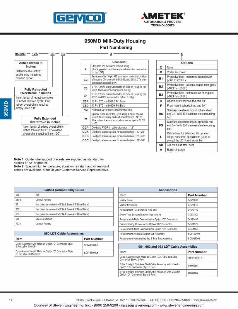
Part Numbering950MD 12A 0B
Fully Retracted Overstroke in Inches
Insert length of retract overstroke in inches followed by “B”. If no retract overstroke is required, simply insert “0B”.
0C XX
Options
X NoneV Vortex air cooler
B1 Protective boot - neoprene coated nylon (-60F to +250F )
B2 Protective boot - silicone coated fiber glass (-100F to +550F )
B3 Protective boot - teflon coated fiber glass (-100F to +500F )
R Rear mount spherical rod end 3/4”F Front mount spherical rod end 3/4”
RSStainless steel rear mount spherical rod end 3/4” with 304 stainless steel mounting bolt
FSStainless steel front mount spherical rod end 3/4” with 304 stainless steel mounting bolt
LDelron liner for extended life cycle on longer horizontal applications (used to protect the LDT’s rod assembly)
SB 304 stainless steel boot A Barrel air purge
Active Stroke in Inches
Determine the “active” stroke to be measured followed by “A”.
Fully Extended Overstroke in Inches
Insert length of extend overstroke in inches followed by “C” If no extend overstroke is required insert “0C”
Connector
XStandard 1/2 inch NPT conduit fitting (It is suggested to order a quick disconnect connector on the LDT)
C2Environmental 10 pin MS connector and mate on side of housing (for use with 951, 952, and 953 LDT’s with connector option E only)
C3 5 Pin, 12mm, Euro Connector on Side of Housing (for 952A /953A w/connector option S only)
C4 6 Pin, 12mm, Euro Connector on Side of Housing (for 953D and SSI w/connector option S only)
C5A 10 Pin STD - to 953A 5 Pin EuroC5D 10 Pin STD - to 953D 6 Pin EuroNC No Head Cover on the 950MD Housing
W
Special Head cover for LDTs using a water cooled jacket. Allows entry and exit of water lines. NOTE: This option does not support connector option C, C2 or C3.
CGP Cord grip PVDF for cable diameter .1”-.3”CGA Cord grip stainless steel for cable diameter .19”-.25”CGB Cord grip stainless steel for cable diameter .25”-.31”CGC Cord grip stainless steel for cable diameter .31”-.38”
950MD Mill-Duty Housing
Courtesy of Steven Engineering, Inc. - (800) 258-9200 - [email protected] - www.stevenengineering.com
171080 N. Crooks Road • Clawson, MI 48017 • 800.635.0289 • 248.435.0700 • Fax 248.435.8120 • www.ametekapt.com
AUTOMATION & PROCESS TECHNOLOGIES
950M
D
Standard 950MD
Mill-Duty with Rear Mount Spherical Rod End
950MD Mill-Duty Housing
Courtesy of Steven Engineering, Inc. - (800) 258-9200 - [email protected] - www.stevenengineering.com
18 1080 N. Crooks Road • Clawson, MI 48017 • 800.635.0289 • 248.435.0700 • Fax 248.435.8120 • www.ametekapt.com
AUTOMATION & PROCESS TECHNOLOGIES
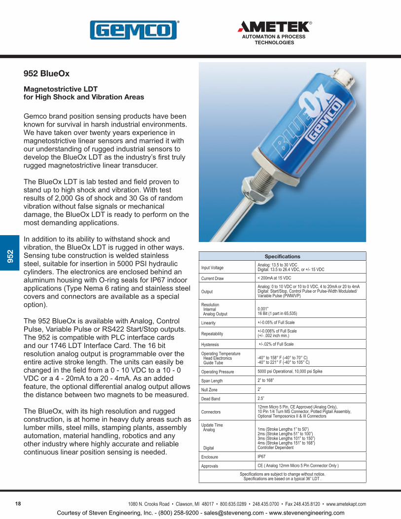
952
Magnetostrictive LDT for High Shock and Vibration Areas
Gemcobrandpositionsensingproductshavebeenknownforsurvivalinharshindustrialenvironments.WehavetakenovertwentyyearsexperienceinmagnetostrictivelinearsensorsandmarrieditwithourunderstandingofruggedindustrialsensorstodeveloptheBlueOxLDTastheindustry’sfirsttrulyruggedmagnetostrictivelineartransducer.
TheBlueOxLDTislabtestedandfieldproventostanduptohighshockandvibration.Withtestresultsof2,000Gsofshockand30Gsofrandomvibrationwithoutfalsesignalsormechanicaldamage,theBlueOxLDTisreadytoperformonthemostdemandingapplications.
Inadditiontoitsabilitytowithstandshockandvibration,theBlueOxLDTisruggedinotherways.Sensingtubeconstructionisweldedstainlesssteel,suitableforinsertionin5000PSIhydrauliccylinders.TheelectronicsareenclosedbehindanaluminumhousingwithO-ringsealsforIP67indoorapplications(TypeNema6ratingandstainlesssteelcoversandconnectorsareavailableasaspecialoption).
The952BlueOxisavailablewithAnalog,ControlPulse,VariablePulseorRS422Start/Stopoutputs.The952iscompatiblewithPLCinterfacecardsandour1746LDTInterfaceCard.The16bitresolutionanalogoutputisprogrammableovertheentireactivestrokelength.Theunitscaneasilybechangedinthefieldfroma0-10VDCtoa10-0VDCora4-20mAtoa20-4mA.Asanaddedfeature,theoptionaldifferentialanalogoutputallowsthedistancebetweentwomagnetstobemeasured.
TheBlueOx,withitshighresolutionandruggedconstruction,isathomeinheavydutyareassuchaslumbermills,steelmills,stampingplants,assemblyautomation,materialhandling,roboticsandanyotherindustrywherehighlyaccurateandreliablecontinuouslinearpositionsensingisneeded.
Specifications
Input Voltage Analog: 13.5 to 30 VDCDigital: 13.5 to 26.4 VDC, or +/- 15 VDC
Current Draw < 200mA at 15 VDC
OutputAnalog: 0 to 10 VDC or 10 to 0 VDC, 4 to 20mA or 20 to 4mADigital: Start/Stop, Control Pulse or Pulse-Width Modulated/Variable Pulse (PWM/VP)
Resolution Internal Analog Output
0.001” 16 Bit (1 part in 65,535)
Linearity +/-0.05% of Full Scale
Repeatability +/-0.006% of Full Scale(+/- .002 inch min.)
Hysteresis +/-.02% of Full Scale
Operating Temperature Head Electronics Guide Tube
-40° to 158° F (-40° to 70° C)-40° to 221° F (-40° to 105° C)
Operating Pressure 5000 psi Operational, 10,000 psi Spike
Span Length 2” to 168”
Null Zone 2”
Dead Band 2.5”
Connectors12mm Micro 5 Pin, CE Approved (Analog Only),10 Pin 1/4 Turn MS Connector, Potted Pigtail Assembly,Optional Temposonics II & III Connectors
Update Time Analog
Digital
1ms (Stroke Lengths 1” to 50”)2ms (Stroke Lengths 51” to 100”)3ms (Stroke Lengths 101” to 150”)4ms (Stroke Lengths 151” to 168”)Controller Dependent
Enclosure IP67
Approvals CE ( Analog 12mm Micro 5 Pin Connector Only )
Specifications are subject to change without notice. Specifications are based on a typical 36” LDT .
952 BlueOx
Courtesy of Steven Engineering, Inc. - (800) 258-9200 - [email protected] - www.stevenengineering.com
191080 N. Crooks Road • Clawson, MI 48017 • 800.635.0289 • 248.435.0700 • Fax 248.435.8120 • www.ametekapt.com
AUTOMATION & PROCESS TECHNOLOGIES
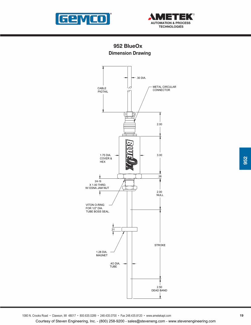
952
Dimension Drawing
2.00
DEAD BAND
3/4-16X 1.00 THRD.
W/ ESNA JAM NUT
CABLE
1.75 DIA.COVER &
.31
.4O DIA.TUBE
1.28 DIA.MAGNET
TUBE BOSS SEAL.
.30 DIA.
NULL
STROKE
2.50
3.00
.38
METAL CIRCULARCONNECTOR
2.00
PIGTAIL
VITON O-RINGFOR 1/2" DIA.
HEX
952 BlueOx
Courtesy of Steven Engineering, Inc. - (800) 258-9200 - [email protected] - www.stevenengineering.com
20 1080 N. Crooks Road • Clawson, MI 48017 • 800.635.0289 • 248.435.0700 • Fax 248.435.8120 • www.ametekapt.com
AUTOMATION & PROCESS TECHNOLOGIES
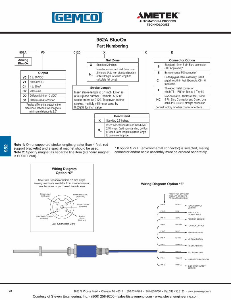
952 Note 1: Onunsupportedstrokelengthsgreaterthan4feet,rod
supportbracket(s)andaspecialmagnetshouldbeused.Note 2: Specifymagnetasseparatelineitem(standardmagnetisSD0400800).
Wiring Diagram Option “E”
LDTConnectorView
UseEuroConnector(micro12mmsinglekeyway)cordsets,availablefrommostconnector
manufacturersorpurchasedfromAmetek.
3
2
4
1
Power 15 to 30 VDC(brown wire)
PositionOutput
(black wire)
Power Supply Common(blue wire)
Program Input(white wire)
5Position Common
(gray wire)
Wiring Diagram Option “S”
WHITE
BLUE
BROWN
GRAY
RED
BLACK
PROGRAM INPUT
NO CONNECTION
POSITION OUTPUT
POSITION COMMON
+15/+30 VDC
POWER SUPPLY
ORANGENO CONNECTION
PIN-OUT FOR STANDARDCIRCULAR CONNECTOAT TRANSDUCER HEAD
GREEN
YELLOW
PURPLE
NO CONNECTION
2nd POSITION COMMON
2nd POWER SUPPLY
COMMON
POWER INPUT
COMMON
PIN-B
PIN-C
PIN-K
PIN-E
PIN-F
PIN-A
PIN-G
PIN-D
PIN-H
PIN-J
Part Numbering 952A 0120
Stroke Length
Insert stroke length to 0.1 inch. Enter as a four-place number. Example: A 12.0” stroke enters as 0120. To convert metric strokes, multiply millimeter value by 0.03937 for inch value.
EXX
Null Zone
X Standard 2 inches.
N_
Insert non-standard Null Zone over 2 inches. (Add non-standard portion of Null length to stroke length to calculate list price)
Connector Option
S Standard 12mm 5 pin Euro connector ( CE Approved )*
E Environmental MS connector*
C_Potted pigtail cable assembly, insert pigtail length in feet. Example: C6 = 6 foot cable.
T Threaded metal connector (fits MTS - “RB” on Tempo IITM or III)
NCNon-corrosive Stainless Steel, 12mm 5 Pin Euro Connector and Cover. Use cable P/N 949013 straight connector.
Consult factory for other connector options.
Dead Band
X Standard 2.5 inches.
D_
Insert non-standard Dead Band over 2.5 inches. (add non-standard portion of Dead Band length to stroke length to calculate list price)
*IfoptionSorE(environmentalconnector)isselected,matingconnectorand/orcableassemblymustbeorderedseparately.
Analog BlueOx
V0
Output
V0 0 to 10 VDCV1 10 to 0 VDCC4 4 to 20mAC2 20 to 4mAD0 Differential 0 to 10 VDC*D1 Differential 4 to 20mA*
*Analog differential output is the difference between two magnets,
minimum distance is 2.5”
952A BlueOx
Courtesy of Steven Engineering, Inc. - (800) 258-9200 - [email protected] - www.stevenengineering.com
211080 N. Crooks Road • Clawson, MI 48017 • 800.635.0289 • 248.435.0700 • Fax 248.435.8120 • www.ametekapt.com
AUTOMATION & PROCESS TECHNOLOGIES
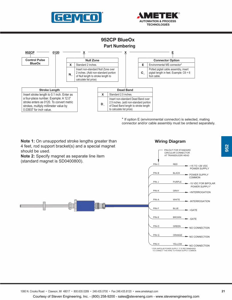
952
Note 1:Onunsupportedstrokelengthsgreaterthan4feet,rodsupportbracket(s)andaspecialmagnetshouldbeused.Note 2:Specifymagnetasseparatelineitem(standardmagnetisSD0400800).
Wiring Diagram
BLUE
WHITE
GRAY
PURPLE
BLACK
RED
-INTERROGATION
+GATE
+INTERROGATION
-15 VDC FOR BIPOLAR
POWER SUPPLY
+15 TO +26 VDC
BROWN-GATE
PIN-OUT FOR STANDARDCIRCULAR CONNECTORAT TRANSDUCER HEAD
GREEN
ORANGE
YELLOW
NO CONNECTION
NO CONNECTION
NO CONNECTION
POWER SUPPLY
COMMON
PIN-C
PIN-B
PIN-J
PIN-K
PIN-A
PIN-F
PIN-E
PIN-D
PIN-G
PIN-H
POWER SUPPLY*
* FOR UNIPOLAR POWER SUPPLY, IT IS RECOMMENDEDTO CONNECT THIS WIRE TO POWER SUPPLY COMMON
Part Numbering 952CP 0120
Stroke Length
Insert stroke length to 0.1 inch. Enter as a four-place number. Example: A 12.0” stroke enters as 0120. To convert metric strokes, multiply millimeter value by 0.03937 for inch value.
EXX
Null Zone
X Standard 2 inches.
N_
Insert non-standard Null Zone over 2 inches. (Add non-standard portion of Null length to stroke length to calculate list price)
Connector Option
E Environmental MS connector*
C_Potted pigtail cable assembly, insert pigtail length in feet. Example: C6 = 6 foot cable.
Dead Band
X Standard 2.5 inches.
D_
Insert non-standard Dead Band over 2.5 inches. (add non-standard portion of Dead Band length to stroke length to calculate list price)
*IfoptionE(environmentalconnector)isselected,matingconnectorand/orcableassemblymustbeorderedseparately.
Control PulseBlueOx
952CP BlueOx
Courtesy of Steven Engineering, Inc. - (800) 258-9200 - [email protected] - www.stevenengineering.com
22 1080 N. Crooks Road • Clawson, MI 48017 • 800.635.0289 • 248.435.0700 • Fax 248.435.8120 • www.ametekapt.com
AUTOMATION & PROCESS TECHNOLOGIES
952
Wiring Diagram
BLUE
WHITE
GRAY
PURPLE
BLACK
RED
-INTERROGATION
+GATE
+INTERROGATION
-15 VDC FOR BIPOLAR
POWER SUPPLY
+15 TO +26 VDC
BROWN-GATE
PIN-OUT FOR STANDARDCIRCULAR CONNECTORAT TRANSDUCER HEAD
GREEN
ORANGE
YELLOW
NO CONNECTION
NO CONNECTION
NO CONNECTION
POWER SUPPLY
COMMON
PIN- C
PIN- B
PIN- J
PIN- K
PIN- A
PIN- F
PIN- E
PIN- D
PIN- G
PIN- H
POWER SUPPLY*
* FOR UNIPOLAR POWER SUPPLY, IT IS RECOMMENDEDTO CONNECT THIS WIRE TO POWER SUPPLY COMMON
Note 1:Onunsupportedstrokelengthsgreaterthan4feet,rodsupportbracket(s)andaspecialmagnetshouldbeused.Note 2:Specifyasmagnetseparatelineitem(standardmagnetisSD0400800).
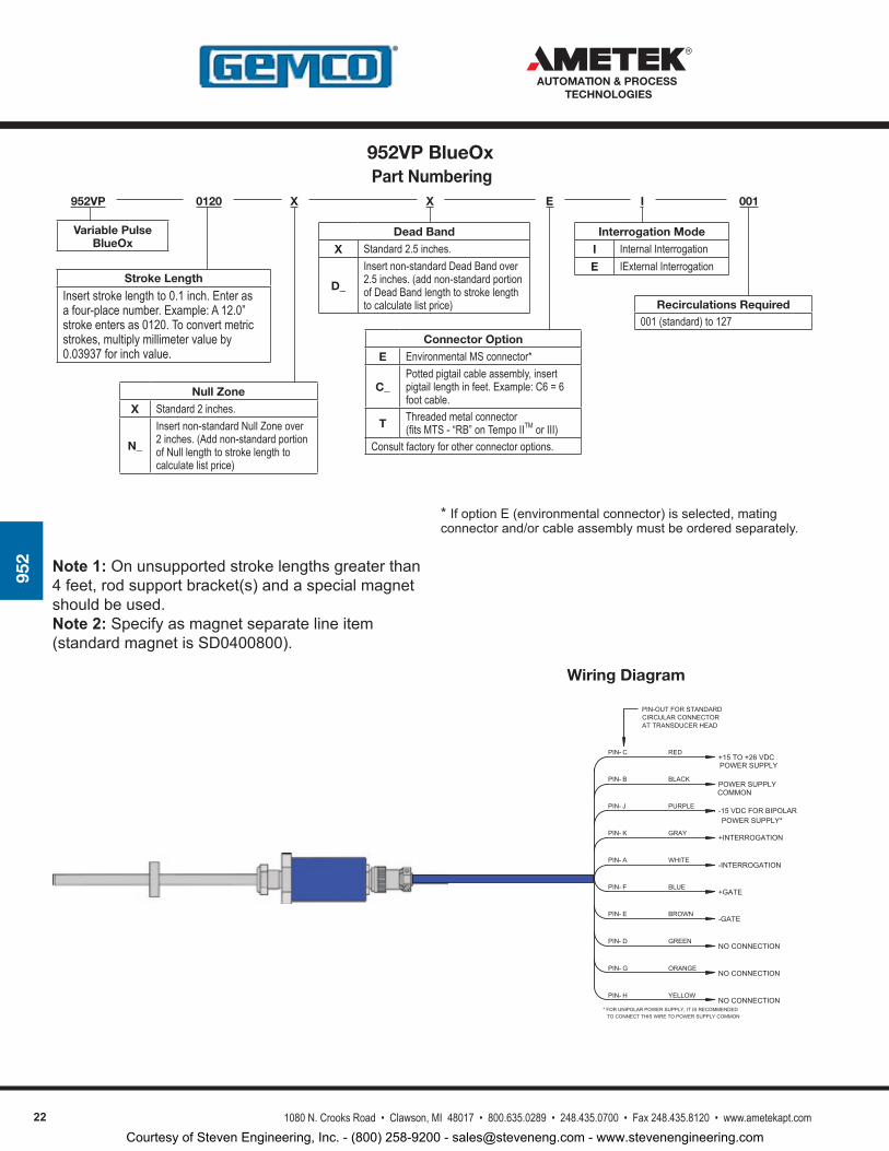
Part Numbering 952VP 0120
Stroke Length
Insert stroke length to 0.1 inch. Enter as a four-place number. Example: A 12.0” stroke enters as 0120. To convert metric strokes, multiply millimeter value by 0.03937 for inch value.
EXX
Null Zone
X Standard 2 inches.
N_
Insert non-standard Null Zone over 2 inches. (Add non-standard portion of Null length to stroke length to calculate list price)
Connector Option
E Environmental MS connector*
C_Potted pigtail cable assembly, insert pigtail length in feet. Example: C6 = 6 foot cable.
T Threaded metal connector (fits MTS - “RB” on Tempo IITM or III)
Consult factory for other connector options.
Dead Band
X Standard 2.5 inches.
D_
Insert non-standard Dead Band over 2.5 inches. (add non-standard portion of Dead Band length to stroke length to calculate list price)
*IfoptionE(environmentalconnector)isselected,matingconnectorand/orcableassemblymustbeorderedseparately.
Variable PulseBlueOx
I
Interrogation Mode
I Internal InterrogationE IExternal Interrogation
001
Recirculations Required001 (standard) to 127
952VP BlueOx
Courtesy of Steven Engineering, Inc. - (800) 258-9200 - [email protected] - www.stevenengineering.com
231080 N. Crooks Road • Clawson, MI 48017 • 800.635.0289 • 248.435.0700 • Fax 248.435.8120 • www.ametekapt.com
AUTOMATION & PROCESS TECHNOLOGIES
952
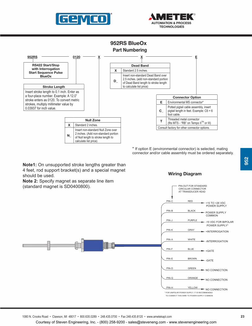
Note1:Onunsupportedstrokelengthsgreaterthan4feet,rodsupportbracket(s)andaspecialmagnetshouldbeused.Note 2:Specifymagnetasseparatelineitem(standardmagnetisSD0400800).
Wiring Diagram
BLUE
WHITE
GRAY
PURPLE
BLACK
RED
-INTERROGATION
+GATE
+INTERROGATION
-15 VDC FOR BIPOLAR
POWER SUPPLY
+15 TO +26 VDC
BROWN-GATE
PIN-OUT FOR STANDARDCIRCULAR CONNECTORAT TRANSDUCER HEAD
GREEN
ORANGE
YELLOW
NO CONNECTION
NO CONNECTION
NO CONNECTION
POWER SUPPLY
COMMON
PIN-C
PIN-B
PIN-J
PIN-K
PIN-A
PIN-F
PIN-E
PIN-D
PIN-G
PIN-H
POWER SUPPLY*
* FOR UNIPOLAR POWER SUPPLY, IT IS RECOMMENDED
TO CONNECT THIS WIRE TO POWER SUPPLY COMMON
Part Numbering 952RS 0120
Stroke Length
Insert stroke length to 0.1 inch. Enter as a four-place number. Example: A 12.0” stroke enters as 0120. To convert metric strokes, multiply millimeter value by 0.03937 for inch value.
EXX
Null Zone
X Standard 2 inches.
N_
Insert non-standard Null Zone over 2 inches. (Add non-standard portion of Null length to stroke length to calculate list price)
Connector Option
E Environmental MS connector*
C_Potted pigtail cable assembly, insert pigtail length in feet. Example: C6 = 6 foot cable.
T Threaded metal connector (fits MTS - “RB” on Tempo IITM or III)
Consult factory for other connector options.
Dead Band
X Standard 2.5 inches.
D_
Insert non-standard Dead Band over 2.5 inches. (add non-standard portion of Dead Band length to stroke length to calculate list price)
*IfoptionE(environmentalconnector)isselected,matingconnectorand/orcableassemblymustbeorderedseparately.
RS422 Start/Stop with Interrogation
Start Sequence Pulse BlueOx
952RS BlueOx
Courtesy of Steven Engineering, Inc. - (800) 258-9200 - [email protected] - www.stevenengineering.com
24 1080 N. Crooks Road • Clawson, MI 48017 • 800.635.0289 • 248.435.0700 • Fax 248.435.8120 • www.ametekapt.com
AUTOMATION & PROCESS TECHNOLOGIES
952
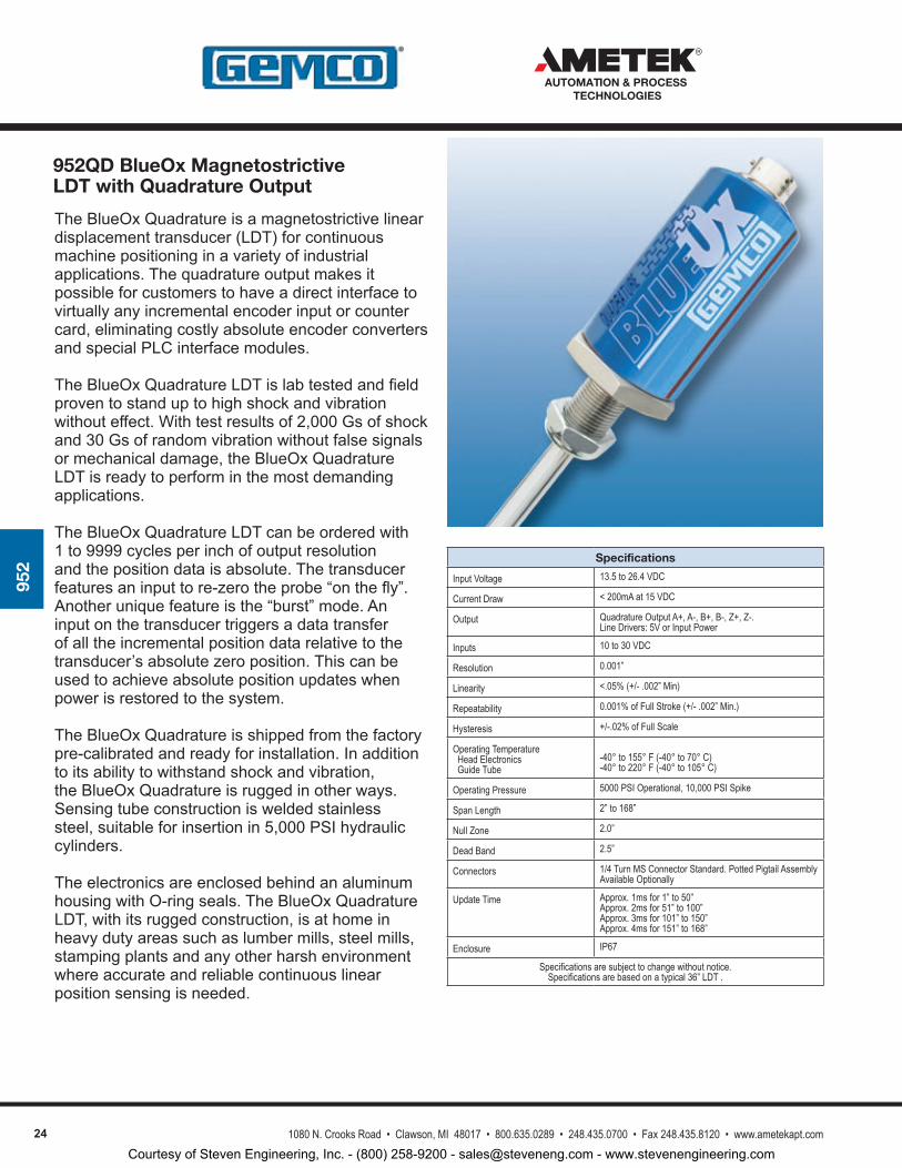
TheBlueOxQuadratureisamagnetostrictivelineardisplacementtransducer(LDT)forcontinuousmachinepositioninginavarietyofindustrialapplications.Thequadratureoutputmakesitpossibleforcustomerstohaveadirectinterfacetovirtuallyanyincrementalencoderinputorcountercard,eliminatingcostlyabsoluteencoderconvertersandspecialPLCinterfacemodules.
TheBlueOxQuadratureLDTislabtestedandfieldproventostanduptohighshockandvibrationwithouteffect.Withtestresultsof2,000Gsofshockand30Gsofrandomvibrationwithoutfalsesignalsormechanicaldamage,theBlueOxQuadratureLDTisreadytoperforminthemostdemandingapplications.
TheBlueOxQuadratureLDTcanbeorderedwith1to9999cyclesperinchofoutputresolutionandthepositiondataisabsolute.Thetransducerfeaturesaninputtore-zerotheprobe“onthefly”.Anotheruniquefeatureisthe“burst”mode.Aninputonthetransducertriggersadatatransferofalltheincrementalpositiondatarelativetothetransducer’sabsolutezeroposition.Thiscanbeusedtoachieveabsolutepositionupdateswhenpowerisrestoredtothesystem.
TheBlueOxQuadratureisshippedfromthefactorypre-calibratedandreadyforinstallation.Inadditiontoitsabilitytowithstandshockandvibration,theBlueOxQuadratureisruggedinotherways.Sensingtubeconstructionisweldedstainlesssteel,suitableforinsertionin5,000PSIhydrauliccylinders.
TheelectronicsareenclosedbehindanaluminumhousingwithO-ringseals.TheBlueOxQuadratureLDT,withitsruggedconstruction,isathomeinheavydutyareassuchaslumbermills,steelmills,stampingplantsandanyotherharshenvironmentwhereaccurateandreliablecontinuouslinearpositionsensingisneeded.
Specifications
Input Voltage 13.5 to 26.4 VDC
Current Draw < 200mA at 15 VDC
Output Quadrature Output A+, A-, B+, B-, Z+, Z-.Line Drivers: 5V or Input Power
Inputs 10 to 30 VDC
Resolution 0.001”
Linearity <.05% (+/- .002” Min)
Repeatability 0.001% of Full Stroke (+/- .002” Min.)
Hysteresis +/-.02% of Full Scale
Operating Temperature Head Electronics Guide Tube
-40° to 155° F (-40° to 70° C)-40° to 220° F (-40° to 105° C)
Operating Pressure 5000 PSI Operational, 10,000 PSI Spike
Span Length 2” to 168”
Null Zone 2.0”
Dead Band 2.5”
Connectors 1/4 Turn MS Connector Standard. Potted Pigtail Assembly Available Optionally
Update Time Approx. 1ms for 1” to 50”Approx. 2ms for 51” to 100”Approx. 3ms for 101” to 150”Approx. 4ms for 151” to 168”
Enclosure IP67
Specifications are subject to change without notice.Specifications are based on a typical 36” LDT .
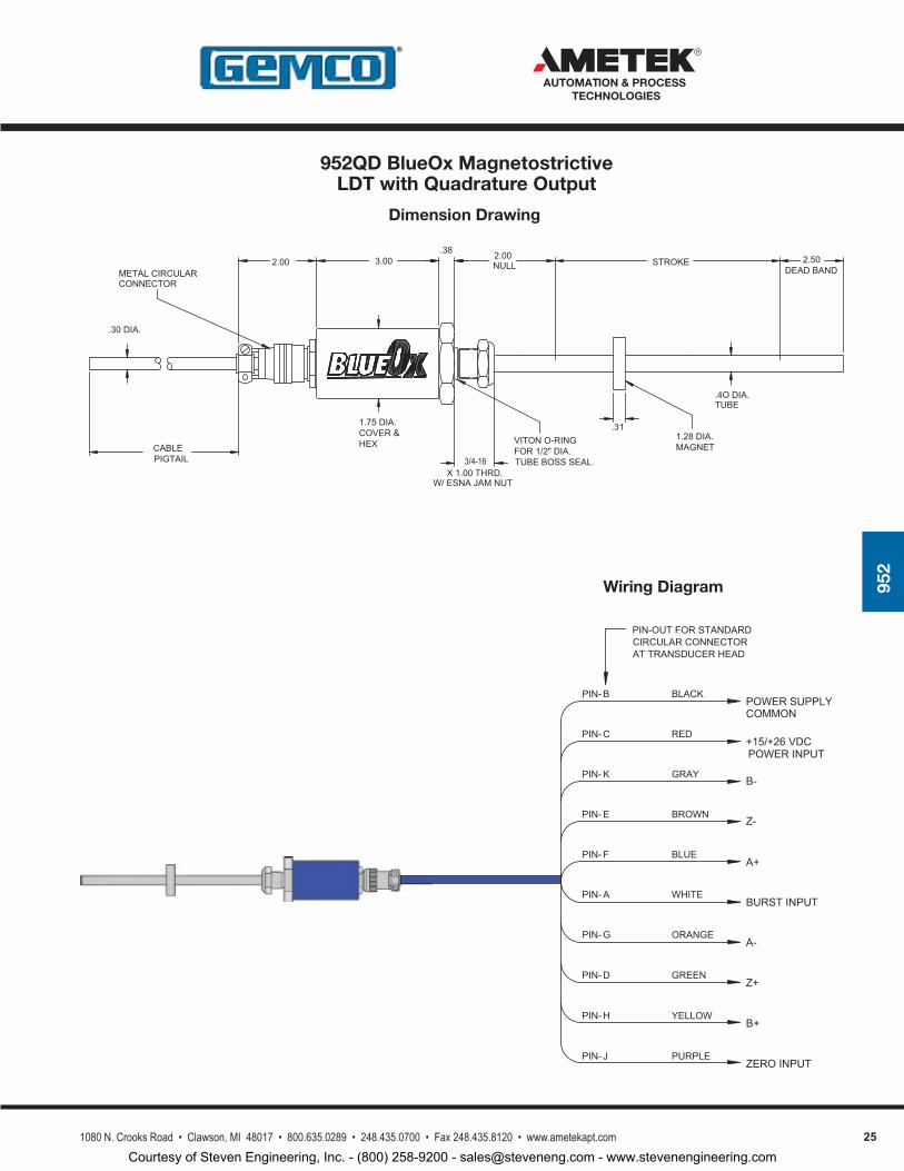
952QD BlueOx Magnetostrictive LDT with Quadrature Output
Courtesy of Steven Engineering, Inc. - (800) 258-9200 - [email protected] - www.stevenengineering.com
251080 N. Crooks Road • Clawson, MI 48017 • 800.635.0289 • 248.435.0700 • Fax 248.435.8120 • www.ametekapt.com
AUTOMATION & PROCESS TECHNOLOGIES
952
Dimension Drawing
Wiring Diagram
2.00DEAD BAND
3/4-16X 1.00 THRD.
W/ ESNA JAM NUT
CABLE
1.75 DIA.COVER &
.31
.4O DIA.TUBE
1.28 DIA.MAGNET
TUBE BOSS SEAL.
.30 DIA.
NULL STROKE 2.503.00.38
METAL CIRCULARCONNECTOR
2.00
PIGTAIL
VITON O-RINGFOR 1/2" DIA.
HEX
WHITE
BLUE
BROWN
GRAY
RED
BLACK
A+
BURST INPUT
Z-
B-
+15/+26 VDC
POWER SUPPLY
ORANGEA-
PIN-OUT FOR STANDARDCIRCULAR CONNECTORAT TRANSDUCER HEAD
GREEN
YELLOW
PURPLE
Z+
B+
ZERO INPUT
COMMON
POWER INPUT
PIN- B
PIN- C
PIN- K
PIN- E
PIN- F
PIN- A
PIN- G
PIN- D
PIN- H
PIN- J
952QD BlueOx Magnetostrictive LDT with Quadrature Output
Courtesy of Steven Engineering, Inc. - (800) 258-9200 - [email protected] - www.stevenengineering.com
26 1080 N. Crooks Road • Clawson, MI 48017 • 800.635.0289 • 248.435.0700 • Fax 248.435.8120 • www.ametekapt.com
AUTOMATION & PROCESS TECHNOLOGIES
952
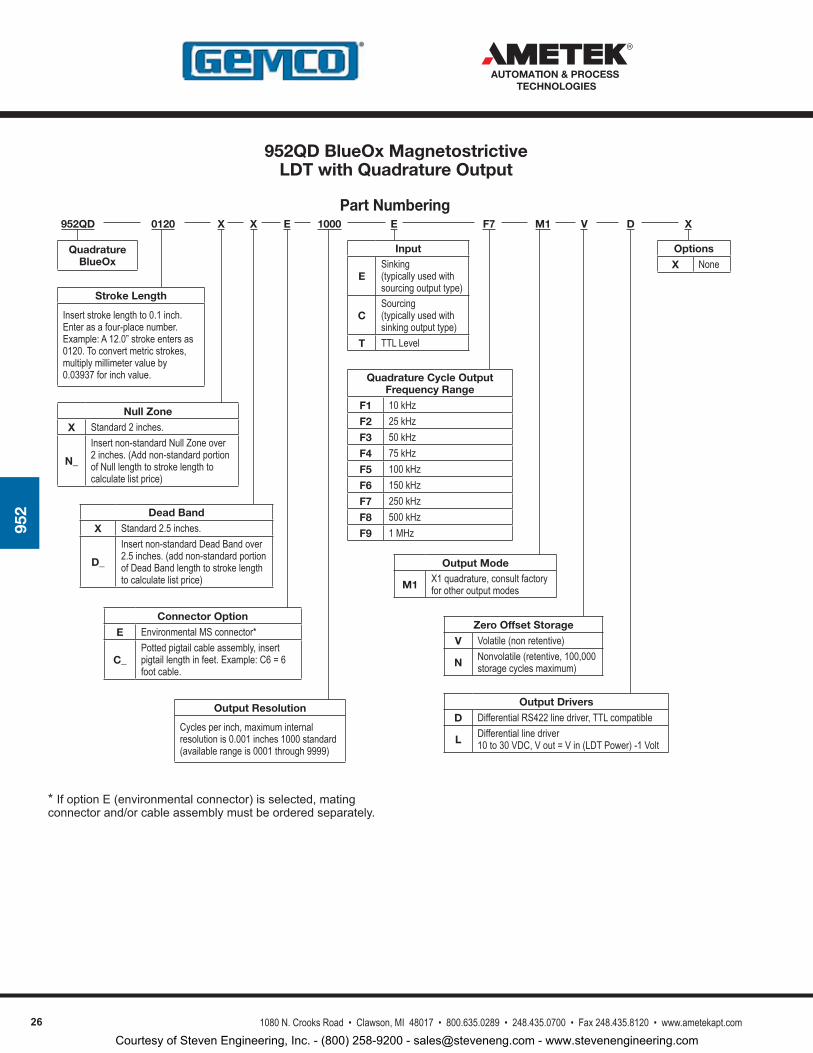
Part Numbering 952QD 0120
Stroke Length
Insert stroke length to 0.1 inch. Enter as a four-place number. Example: A 12.0” stroke enters as 0120. To convert metric strokes, multiply millimeter value by 0.03937 for inch value.
EXX
Null Zone
X Standard 2 inches.
N_
Insert non-standard Null Zone over 2 inches. (Add non-standard portion of Null length to stroke length to calculate list price)
Connector Option
E Environmental MS connector*
C_Potted pigtail cable assembly, insert pigtail length in feet. Example: C6 = 6 foot cable.
Dead Band
X Standard 2.5 inches.
D_
Insert non-standard Dead Band over 2.5 inches. (add non-standard portion of Dead Band length to stroke length to calculate list price)
*IfoptionE(environmentalconnector)isselected,matingconnectorand/orcableassemblymustbeorderedseparately.
Quadrature BlueOx
1000
Output Resolution
Cycles per inch, maximum internal resolution is 0.001 inches 1000 standard (available range is 0001 through 9999)
M1F7E
Input
ESinking (typically used with sourcing output type)
CSourcing (typically used with sinking output type)
T TTL Level
Output Mode
M1 X1 quadrature, consult factory for other output modes
Quadrature Cycle Output Frequency Range
F1 10 kHzF2 25 kHzF3 50 kHzF4 75 kHzF5 100 kHzF6 150 kHzF7 250 kHzF8 500 kHzF9 1 MHz
V XD
Output Drivers
D Differential RS422 line driver, TTL compatible
L Differential line driver 10 to 30 VDC, V out = V in (LDT Power) -1 Volt
Options
X None
Zero Offset Storage
V Volatile (non retentive)
N Nonvolatile (retentive, 100,000 storage cycles maximum)
952QD BlueOx Magnetostrictive LDT with Quadrature Output
Courtesy of Steven Engineering, Inc. - (800) 258-9200 - [email protected] - www.stevenengineering.com
271080 N. Crooks Road • Clawson, MI 48017 • 800.635.0289 • 248.435.0700 • Fax 248.435.8120 • www.ametekapt.com
AUTOMATION & PROCESS TECHNOLOGIES
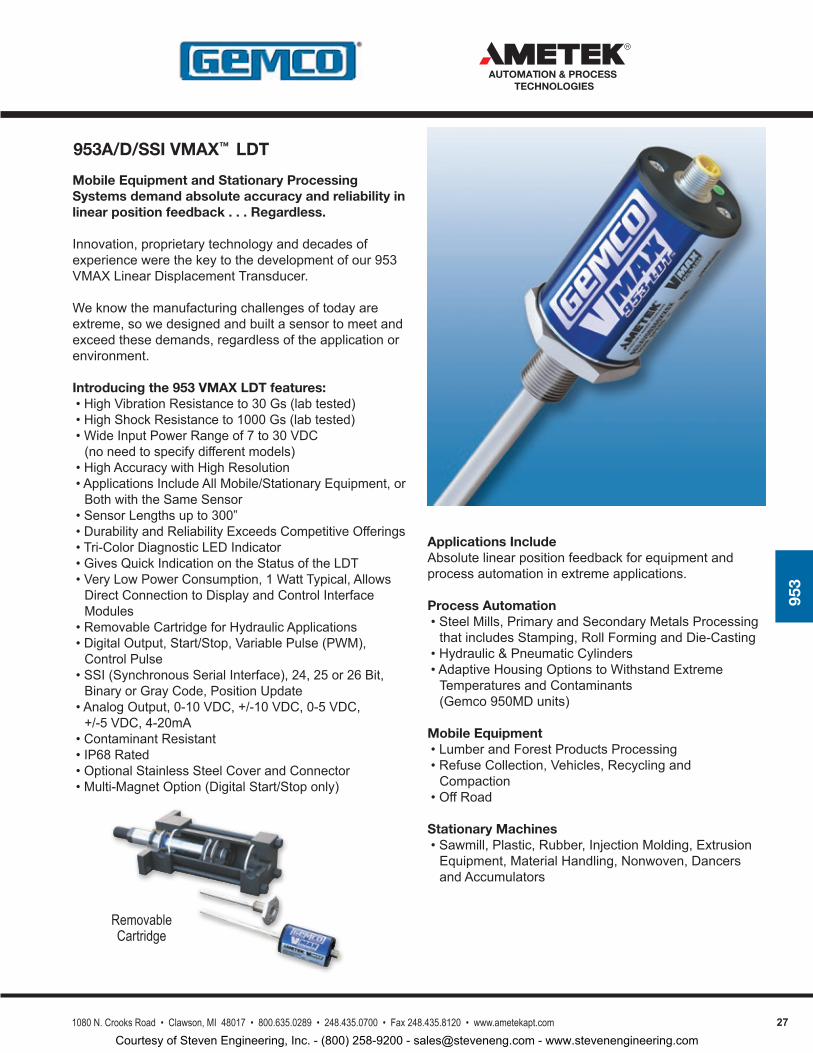
953
Mobile Equipment and Stationary Processing Systems demand absolute accuracy and reliability in linear position feedback . . . Regardless.
Innovation,proprietarytechnologyanddecadesofexperiencewerethekeytothedevelopmentofour953VMAXLinearDisplacementTransducer.
Weknowthemanufacturingchallengesoftodayareextreme,sowedesignedandbuiltasensortomeetandexceedthesedemands,regardlessoftheapplicationorenvironment.
Introducing the 953 VMAX LDT features:•HighVibrationResistanceto30Gs(labtested)•HighShockResistanceto1000Gs(labtested)•WideInputPowerRangeof7to30VDC(noneedtospecifydifferentmodels)
•HighAccuracywithHighResolution•ApplicationsIncludeAllMobile/StationaryEquipment,orBothwiththeSameSensor
•SensorLengthsupto300”•DurabilityandReliabilityExceedsCompetitiveOfferings•Tri-ColorDiagnosticLEDIndicator•GivesQuickIndicationontheStatusoftheLDT•VeryLowPowerConsumption,1WattTypical,AllowsDirectConnectiontoDisplayandControlInterfaceModules
•RemovableCartridgeforHydraulicApplications•DigitalOutput,Start/Stop,VariablePulse(PWM),ControlPulse
•SSI(SynchronousSerialInterface),24,25or26Bit,BinaryorGrayCode,PositionUpdate
•AnalogOutput,0-10VDC,+/-10VDC,0-5VDC,+/-5VDC,4-20mA
•ContaminantResistant•IP68Rated•OptionalStainlessSteelCoverandConnector•Multi-MagnetOption(DigitalStart/Stoponly)
Applications IncludeAbsolutelinearpositionfeedbackforequipmentandprocessautomationinextremeapplications.
Process Automation•SteelMills,PrimaryandSecondaryMetalsProcessingthatincludesStamping,RollFormingandDie-Casting
•Hydraulic&PneumaticCylinders•AdaptiveHousingOptionstoWithstandExtremeTemperaturesandContaminants(Gemco950MDunits)
Mobile Equipment•LumberandForestProductsProcessing•RefuseCollection,Vehicles,RecyclingandCompaction
•OffRoad
Stationary Machines•Sawmill,Plastic,Rubber,InjectionMolding,ExtrusionEquipment,MaterialHandling,Nonwoven,DancersandAccumulators
Removable Cartridge
953A/D/SSI VMAX™ LDT
Courtesy of Steven Engineering, Inc. - (800) 258-9200 - [email protected] - www.stevenengineering.com
28 1080 N. Crooks Road • Clawson, MI 48017 • 800.635.0289 • 248.435.0700 • Fax 248.435.8120 • www.ametekapt.com
AUTOMATION & PROCESS TECHNOLOGIES
953
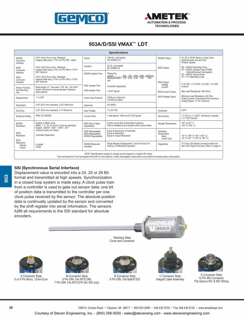
Specifications
953SSI Connector Interface
953D Connector Interface
953A Connector Interface
6 Pin 12mm Euro micro, Standard. Integral cable ass'y, 7 Pin or 8 Pin DIN - option
6 Pin 12mm Euro micro, Standard.Integral cable ass'y, 6 Pin or 8 Pin DIN or 10 Pin MS- Optional
5 Pin 12mm Euro micro, Standard Integral cable ass'y, 6 Pin or 8 Pin DIN or 10 Pin MS- Optional
Shock 1000 Gs (lab tested)IEC 60068-2-27
953SSI Output
953D Output
953A Output VoltageCurrent
953A Current Output
953A Voltage Output
24, 25 or 26 Bit, Binary or Gray Code (optional parity and error bit), Position Update
RS = RS422 Start/Stop PulseVP = RS422 Variable Pulse (PWM), Internal/External InterrogationCP = RS422 Control PulseTP = TTL Start/Stop Pulse
0-10 VDC, +/-10 VDC, 0-5 VDC, +/-5 VDC4-20mA
Max Load Resistance: 500 Ohms
Minimum Load Resistance: 2K OhmOutput Current: Guaranteed 5mA minimumAnalog Ripple: ≤1 mV maximum
Vibration 30 Gs (lab tested)IEC 60068-2-6
953SSI Update Time
953D Update Time
953A Update Time
Measuring Length 300 750 1000 2000 5000mmMeasurements/sec.
3.7k 3.0k 2.3k 1.2k 0.5k
Controller Dependant
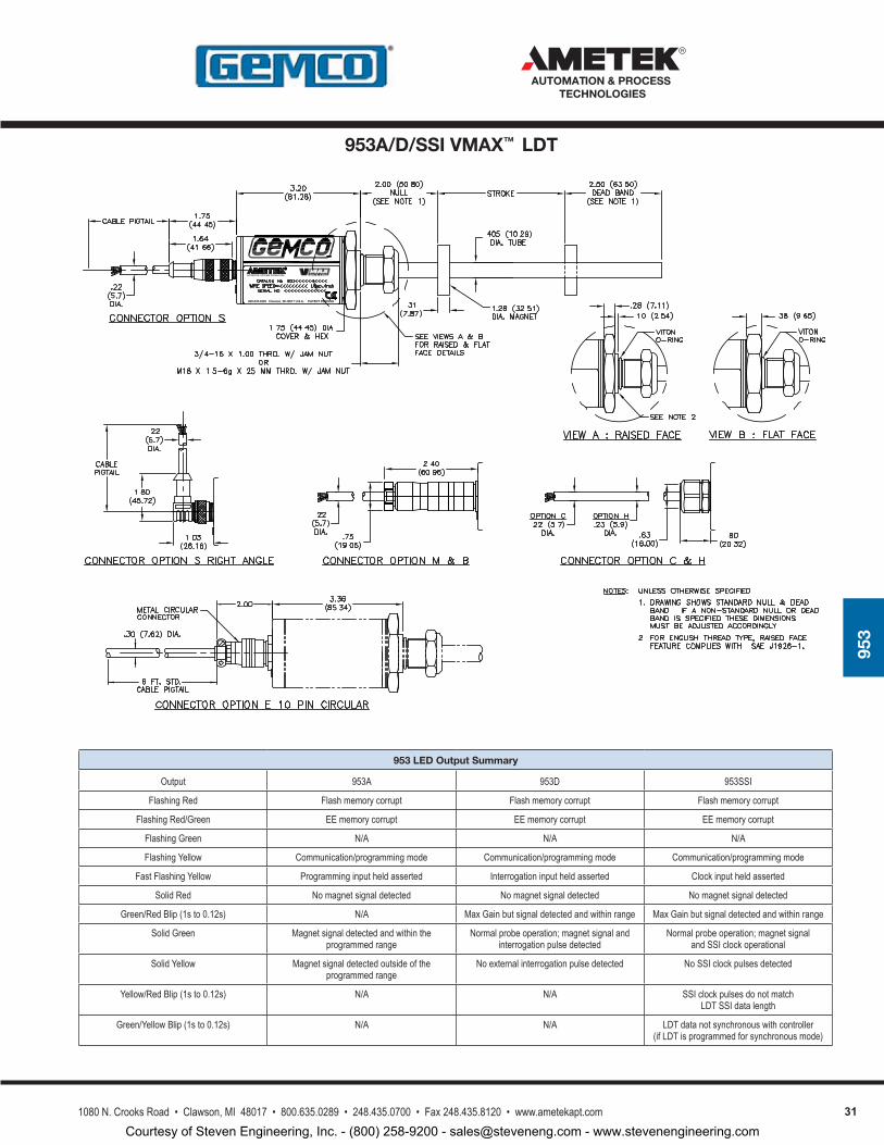
< 2mS TypicalSensor Housing and Mounting Hex
Body length 3.2”, hex base 1 3/4” dia., 3/4”x16x1” thread. Aluminum housing standard, stainless steel optional.
Displacement 1” to 300" Guide Tube Pressure 5,000 psi continuous (10,000 psi spike)
Dead Band 2.50" (63.5 mm) standard, (2.25” Minimum) Approvals CE (EMC)
Null Zone 2.00" (50.8 mm) standard, (1.5” Minimum) Input Voltage 7 to 30 VDC Hysteresis 0.001”
Enclosure Rating IP68, IEC 600529 Current Draw 1 watt typical*, 40mA at 24 VDC typical Non-linearity < 0.01% or +/- 0.005”, whichever is greater, (+/- 0.002 Typical)
953SSI Resolution
953D Resolution
953A Resolution
InternalOutput
English or Metric UnitsMetric: 1, 5, 10, 20 micron (5 micron standard)English: .00005", .0001", .0005", .001"Consult Factory for Others.
Controller Dependant
0.00006”16-Bit
953A Zero & Span Adjustability
Factory set at Null & Dead Band locations Field re-settable at any location within active stroke
Storage Temperature -40° to 221° F (-40° to 105° C)
953D Repeatability 953A Repeatability 953SSI Repeatability
Equal to Resolution of ControllerEqual to ResolutionEqual to Output Resolution
Operating Temperature
HeadGuide Tube
-40° to 185° F ( -40° to 85° C)-40° to 221° F (-40° to 105° C)
953SSI MeasuredVariables
Single Magnet Displacement, Consult Factory for Velocity or Differential Operation
Diagnostics Tri-Color LED beside connector/cable exit,See 'LED Output Summary Table' on page 31
NOTE: Specifications subject to change and are based on a typical 48” stroke. *One watt typical at 1ms interrogation time with no recirculations. Faster interrogation times and/or recirculations increase power consumption.
SSI (Synchronous Serial Interface)Displacementvalueisencodedintoa24,25or26Bitformatandtransmittedathighspeeds.Synchronizationinaclosedloopsystemismadeeasy.Aclockpulsetrainfromacontrollerisusedtogateoutsensordata:onebitofpositiondataistransmittedtothecontrollerperoneclockpulsereceivedbythesensor.Theabsolutepositiondataiscontinuallyupdatedbythesensorandconvertedbytheshiftregisterintoserialinformation.ThesensorsfulfillallrequirementstotheSSIstandardforabsoluteencoders.
S Connector Style5 or 6 Pin Micro, 12mm Euro
M Connector Style6 Pin DIN, Fits MTS D60
7 Pin DIN, Fits MTS D70 (for SSI only)
B Connector Style8 Pin DIN, Fits Balluff S32
C Connector StyleIntegral Cable Assembly
Stainless Steel Cover and Connector
E Connector Style10 Pin MS Connector,
Fits Gemco 951 & 952 Wiring
953A/D/SSI VMAX™ LDT
Courtesy of Steven Engineering, Inc. - (800) 258-9200 - [email protected] - www.stevenengineering.com
291080 N. Crooks Road • Clawson, MI 48017 • 800.635.0289 • 248.435.0700 • Fax 248.435.8120 • www.ametekapt.com
AUTOMATION & PROCESS TECHNOLOGIES
953
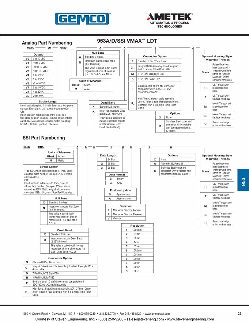
Analog Part Numbering
SSI Part Numbering
953A 0120V0 X
Stroke LengthInsert stroke length to 0.1 inch. Enter as a four-place number. Example: A 12.0” stroke enters as 0120. ORInsert stroke in millimeters to 1mm. Enter as a four-place number. Example: 305mm stroke entered as 0305M. Metric length includes metric mounting, M18x1.5. Unless Specified Otherwise.
SXX
Null Zone
X Standard 2 inches.
N Insert non-standard Null Zone (1.5” Minimum).This value is called out in inches regardless of units of measure (i.e. 1.5” Null Zone = N1.5)
Units of Measure
Blank Inches.M Metric
Options
X None
S
Stainless Steel cover and connector. Only available with connector options S, C, and H.
Dead Band
X Standard 2.5 inches.
D Insert non-standard Dead Band (2.25” Minimum)This value is called out in inches regardless of units of measure (i.e. 2.25” Dead Band = D2.25)
Output
V0 0 to 10 VDCV1 10 to 0 VDCV2 -10 to 10 VDCV3 10 to -10 VDCV4 0 to 5 VDCV5 5 to 0 VDCV6 -5 to 5 VDCV7 5 to -5 VDCC4 4 to 20mAC2 20 to 4mA
Connector Option
S Standard 5 Pin, 12mm Euro
C_ Integral Cable Assembly. Insert length in feet. Example: C6 = 6 foot cable.
M 6 Pin DIN, MTS Style D60
B 8 Pin DIN, Balluff S32
EEnvironmental 10 Pin MS Connector compatible w/951 & 952 LDTs w/connector option “E”.
H_
High Temp., Integral cable assembly 200º C Teflon Cable. Insert length in feet. Example: H6= 6 foot High Temp Teflon Cable.
Optional Housing Style - Mounting Threads
Blank
Raised face hex base (standard) - Threads will be the same as “Units of Measure” unless specified otherwise.
RUS Threads with raised face hex base
F US Threads with flat face hex base
MMetric Threads with raised face hex base
N Metric Threads with flat face hex base
C Sensor cartridge only - No hex base
VP953S 0120 1
Stroke Length1" to 300". Insert stroke length to 0.1 inch. Enter as a four-place number. Example: A 12.0” stroke enters as 0120. ORInsert stroke in millimeters to 1mm. Enter as a four-place number. Example: 305mm stroke entered as 0305. Metric length includes metric mounting, M18x1.5. Unless Specified Otherwise
SXX
Null Zone
X Standard 2 inches.
N Insert non-standard Null Zone (1.5” Minimum).This value is called out in inches regardless of units of measure (i.e. 1.5” Null Zone = N1.5)
Data Length
1 24 Bits2 25 Bits3 26 Bits
B
Data Format
B BinaryG Gray
X
Options
X NoneA Alarm Bit 25, Parity 26
SStainless Steel cover and connector. Only available with connector options S, C and H.
Units of Measure
Blank InchesM Metric
S
Position Update
S SynchronousA Asynchronous
F
Direction
F Measures Direction ForwardR Measures Direction ReverseV Velocity
1
Resolution
1 .005mm 2 .01mm 3 .05mm 4 .1mm 5 .02mm 6 .002mm 7 .001mm 8 .00005"9 .0001"A .0005"B .001"
Optional Housing Style - Mounting Threads
Blank
Raised face hex base (standard) - Threads will be the same as “Units of Measure” unless specified otherwise.
RUS Threads with raised face hex base
F US Threads with flat face hex base
MMetric Threads with raised face hex base
N Metric Threads with flat face hex base
C Sensor cartridge only - No hex base
Connector Option
S Standard 6 Pin, 12mm Euro
C_ Integral Cable Assembly. Insert length in feet. Example: C6 = 6 foot cable.
M 7 Pin DIN, MTS Style D70 B 8 Pin DIN, Balluff S32
E Environmental 10 pin MS connector compatible with SDO439700 LXX cable assembly
H_High Temp., Integral cable assembly 200º C Teflon Cable. Insert length in feet. Example: H6= 6 foot High Temp Teflon Cable.
Dead Band
X Standard 2.5 inches.
D Insert non-standard Dead Band (2.25” Minimum)This value is called out in inches regardless of units of measure (i.e. 2.25” Dead Band = D2.25)
953A/D/SSI VMAX™ LDT
Courtesy of Steven Engineering, Inc. - (800) 258-9200 - [email protected] - www.stevenengineering.com
30 1080 N. Crooks Road • Clawson, MI 48017 • 800.635.0289 • 248.435.0700 • Fax 248.435.8120 • www.ametekapt.com
AUTOMATION & PROCESS TECHNOLOGIES
953
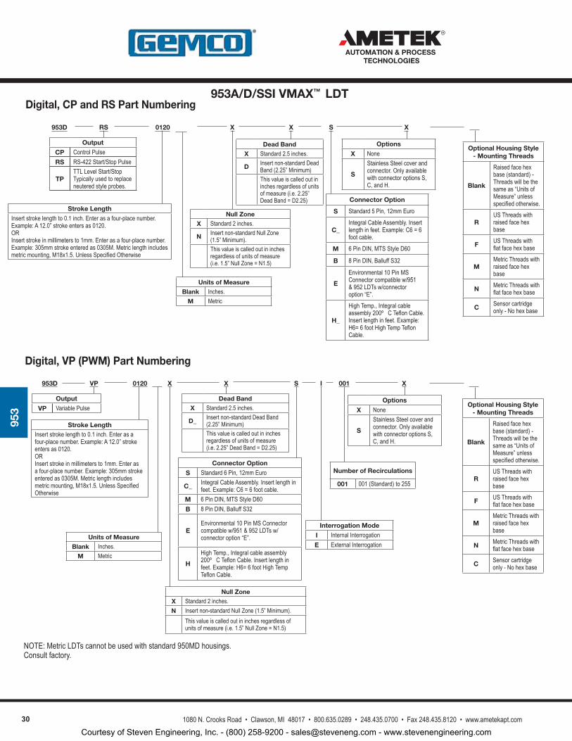
NOTE: Metric LDTs cannot be used with standard 950MD housings. Consult factory.
Digital, VP (PWM) Part Numbering
Digital, CP and RS Part Numbering
953D 0120RS
Stroke LengthInsert stroke length to 0.1 inch. Enter as a four-place number. Example: A 12.0” stroke enters as 0120. ORInsert stroke in millimeters to 1mm. Enter as a four-place number. Example: 305mm stroke entered as 0305M. Metric length includes metric mounting, M18x1.5. Unless Specified Otherwise
Output
CP Control PulseRS RS-422 Start/Stop Pulse
TPTTL Level Start/StopTypically used to replace neutered style probes.
SXX X
Options
X None
S
Stainless Steel cover and connector. Only available with connector options S, C, and H.
Connector Option
S Standard 5 Pin, 12mm Euro
C_Integral Cable Assembly. Insert length in feet. Example: C6 = 6 foot cable.
M 6 Pin DIN, MTS Style D60
B 8 Pin DIN, Balluff S32
E
Environmental 10 Pin MS Connector compatible w/951 & 952 LDTs w/connector option “E”.
H_
High Temp., Integral cable assembly 200º C Teflon Cable. Insert length in feet. Example: H6= 6 foot High Temp Teflon Cable.
Optional Housing Style - Mounting Threads
Blank
Raised face hex base (standard) - Threads will be the same as “Units of Measure” unless specified otherwise.
RUS Threads with raised face hex base
F US Threads with flat face hex base
MMetric Threads with raised face hex base
N Metric Threads with flat face hex base
C Sensor cartridge only - No hex base
953D 0120VP I
Stroke LengthInsert stroke length to 0.1 inch. Enter as a four-place number. Example: A 12.0” stroke enters as 0120. ORInsert stroke in millimeters to 1mm. Enter as a four-place number. Example: 305mm stroke entered as 0305M. Metric length includes metric mounting, M18x1.5. Unless Specified Otherwise
Output
VP Variable Pulse
SXX
Interrogation Mode
I Internal InterrogationE External Interrogation
001
Number of Recirculations
001 001 (Standard) to 255
X
Options
X None
S
Stainless Steel cover and connector. Only available with connector options S, C, and H.
Connector Option
S Standard 6 Pin, 12mm Euro
C_ Integral Cable Assembly. Insert length in feet. Example: C6 = 6 foot cable.
M 6 Pin DIN, MTS Style D60 B 8 Pin DIN, Balluff S32
EEnvironmental 10 Pin MS Connector compatible w/951 & 952 LDTs w/connector option “E”.
H
High Temp., Integral cable assembly 200º C Teflon Cable. Insert length in feet. Example: H6= 6 foot High Temp Teflon Cable.
Optional Housing Style - Mounting Threads
Blank
Raised face hex base (standard) - Threads will be the same as “Units of Measure” unless specified otherwise.
RUS Threads with raised face hex base
F US Threads with flat face hex base
MMetric Threads with raised face hex base
N Metric Threads with flat face hex base
C Sensor cartridge only - No hex base
Units of Measure
Blank Inches.M Metric
Units of Measure
Blank Inches.M Metric
Dead Band
X Standard 2.5 inches.
D Insert non-standard Dead Band (2.25” Minimum)This value is called out in inches regardless of units of measure (i.e. 2.25” Dead Band = D2.25)
Null Zone
X Standard 2 inches.
N Insert non-standard Null Zone (1.5” Minimum).This value is called out in inches regardless of units of measure (i.e. 1.5” Null Zone = N1.5)
Dead Band
X Standard 2.5 inches.
D_ Insert non-standard Dead Band (2.25” Minimum)This value is called out in inches regardless of units of measure (i.e. 2.25” Dead Band = D2.25)
Null Zone
X Standard 2 inches.N Insert non-standard Null Zone (1.5” Minimum).
This value is called out in inches regardless of units of measure (i.e. 1.5” Null Zone = N1.5)
953A/D/SSI VMAX™ LDT
Courtesy of Steven Engineering, Inc. - (800) 258-9200 - [email protected] - www.stevenengineering.com
311080 N. Crooks Road • Clawson, MI 48017 • 800.635.0289 • 248.435.0700 • Fax 248.435.8120 • www.ametekapt.com
AUTOMATION & PROCESS TECHNOLOGIES
953
Optional Housing Style - Mounting Threads
Blank
Raised face hex base (standard) - Threads will be the same as “Units of Measure” unless specified otherwise.
RUS Threads with raised face hex base
F US Threads with flat face hex base
MMetric Threads with raised face hex base
N Metric Threads with flat face hex base
C Sensor cartridge only - No hex base
953 LED Output Summary
Output 953A 953D 953SSI
Flashing Red Flash memory corrupt Flash memory corrupt Flash memory corrupt
Flashing Red/Green EE memory corrupt EE memory corrupt EE memory corrupt
Flashing Green N/A N/A N/A
Flashing Yellow Communication/programming mode Communication/programming mode Communication/programming mode
Fast Flashing Yellow Programming input held asserted Interrogation input held asserted Clock input held asserted
Solid Red No magnet signal detected No magnet signal detected No magnet signal detected
Green/Red Blip (1s to 0.12s) N/A Max Gain but signal detected and within range Max Gain but signal detected and within range
Solid Green Magnet signal detected and within the programmed range
Normal probe operation; magnet signal and interrogation pulse detected
Normal probe operation; magnet signal and SSI clock operational
Solid Yellow Magnet signal detected outside of the programmed range
No external interrogation pulse detected No SSI clock pulses detected
Yellow/Red Blip (1s to 0.12s) N/A N/A SSI clock pulses do not match LDT SSI data length
Green/Yellow Blip (1s to 0.12s) N/A N/A LDT data not synchronous with controller (if LDT is programmed for synchronous mode)
953A/D/SSI VMAX™ LDT
Courtesy of Steven Engineering, Inc. - (800) 258-9200 - [email protected] - www.stevenengineering.com
32 1080 N. Crooks Road • Clawson, MI 48017 • 800.635.0289 • 248.435.0700 • Fax 248.435.8120 • www.ametekapt.com
AUTOMATION & PROCESS TECHNOLOGIES
953
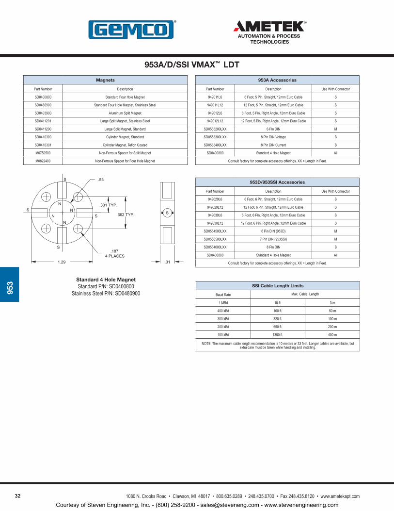
953A Accessories
Part Number Description Use With Connector
949011L6 6 Foot, 5 Pin, Straight, 12mm Euro Cable S
949011L12 12 Foot, 5 Pin, Straight, 12mm Euro Cable S
949012L6 6 Foot, 5 Pin, Right Angle, 12mm Euro Cable S
949012L12 12 Foot, 5 Pin, Right Angle, 12mm Euro Cable S
SD0553200LXX 6 Pin DIN M
SD0553300LXX 8 Pin DIN Voltage B
SD0553400LXX 8 Pin DIN Current B
SD0400800 Standard 4 Hole Magnet All
Consult factory for complete accessory offerings. XX = Length in Feet.
953D/953SSI Accessories
Part Number Description Use With Connector
949029L6 6 Foot, 6 Pin, Straight, 12mm Euro Cable S
949029L12 12 Foot, 6 Pin, Straight, 12mm Euro Cable S
949030L6 6 Foot, 6 Pin, Right Angle, 12mm Euro Cable S
949030L12 12 Foot, 6 Pin, Right Angle, 12mm Euro Cable S
SD0554500LXX 6 Pin DIN (953D) M
SD0558500LXX 7 Pin DIN (953SSI) M
SD0554600LXX 8 Pin DIN B
SD0400800 Standard 4 Hole Magnet All
Consult factory for complete accessory offerings. XX = Length in Feet.
Magnets
Part Number Description
SD0400800 Standard Four Hole Magnet
SD0480900 Standard Four Hole Magnet, Stainless Steel
SD0403900 Aluminum Split Magnet
SD0411201 Large Split Magnet, Stainless Steel
SD0411200 Large Split Magnet, Standard
SD0410300 Cylinder Magnet, Standard
SD0410301 Cylinder Magnet, Teflon Coated
M0750500 Non-Ferrous Spacer for Split Magnet
M0822400 Non-Ferrous Spacer for Four Hole Magnet
SN
NN
N
S
S
S
S
1.29 .31
.53
.331TYP.
.662TYP.
.1874PLACES
Standard 4 Hole MagnetStandard P/N: SD0400800
Stainless Steel P/N: SD0480900SSI Cable Length Limits
Baud Rate Max. Cable Length
1 MBd 10 ft. 3 m
400 kBd 160 ft. 50 m
300 kBd 320 ft. 100 m
200 kBd 650 ft. 200 m
100 kBd 1300 ft. 400 m
NOTE: The maximum cable length recommendation is 10 meters or 33 feet. Longer cables are available, but extra care must be taken while handling and installing.
953A/D/SSI VMAX™ LDT
Courtesy of Steven Engineering, Inc. - (800) 258-9200 - [email protected] - www.stevenengineering.com
331080 N. Crooks Road • Clawson, MI 48017 • 800.635.0289 • 248.435.0700 • Fax 248.435.8120 • www.ametekapt.com
AUTOMATION & PROCESS TECHNOLOGIES
955
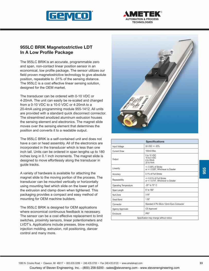
955LC BRIK Magnetostrictive LDT In A Low Profile Package
The955LCBRIKisanaccurate,programmablezeroandspan,non-contactlinearpositionsensorinaneconomical,lowprofilepackage.Thesensorutilizesourfieldprovenmagnetostrictivetechnologytogiveabsoluteposition,repeatableto.01%ofthesensingdistance.The955LCisacosteffectivelinearsensingsolution,designedfortheOEMmarket.
Thetransducercanbeorderedwith0-10VDCor4-20mA.Theunitcaneasilybere-scaledandchangedfroma0-10VDCtoa10-0VDCor4-20mAtoa20-4mAusingprogrammingmodule955-1412.Allunitsareprovidedwithastandardquickdisconnectconnector.Thestreamlinedanodizedaluminumextrusionhousesthesensingelementandelectronics.Themagnetslidemovesoverthesensingelementthatdeterminesthepositionandconvertsittoareadableoutput.
The955LCBRIKisaself-containedunitanddoesnothaveacanorheadassembly.Alloftheelectronicsareincorporatedinthetransducerwhichislessthanoneinchtall.Unitscanbeorderedinspanlengthsupto180incheslongin0.1inchincrements.Themagnetslideisdesignedtomoveeffortlesslyalongthetransduceringuidetracks.
Avarietyofhardwareisavailableforattachingthemagnetslidetothemovingportionoftheprocess.Thetransducercanbemountedverticallyorhorizontallyusingmountingfeetwhichslideonthelowerpartoftheextrusionandclampdownwhentightened.ThispackagingprovidesacompactandeasymethodofmountingforOEMmachinebuilders.
The955LCBRIKisdesignedforOEMapplicationswhereeconomicalcontinuousfeedbackisnecessary.Thesensorcanbeacosteffectivereplacementtolimitswitches,proximitysensors,linearpotentiometersandLVDT’s.Applicationsincludepresses,blowmolding,injectionmolding,extrusion,rollpositioning,dancercontrolandmanymore.
Specifications
Input Voltage 24 VDC +/- 20%
Current Draw 100mA Max.
Output0 to 10 VDC10 to 0 VDC4 to 20mA20 to 4mA
Linearity +/- 0.05% of Strokeor +/- 0.028”, Whichever is Greater
Accuracy 0.1% of Full Stroke
Repeatability +/- 0.01% of Full Strokeor +/- 0.014”, Whichever is Greater
Operating Temperature -20° to 70° C
Span Length 6” to 180”
Null Zone 3.00”
Dead Band 1.50”
Connector Standard 4 Pin Micro 12mm Euro Connector
Agency Approvals CE Approved
Enclosure IP67
Specifcation may change without notice.
Courtesy of Steven Engineering, Inc. - (800) 258-9200 - [email protected] - www.stevenengineering.com
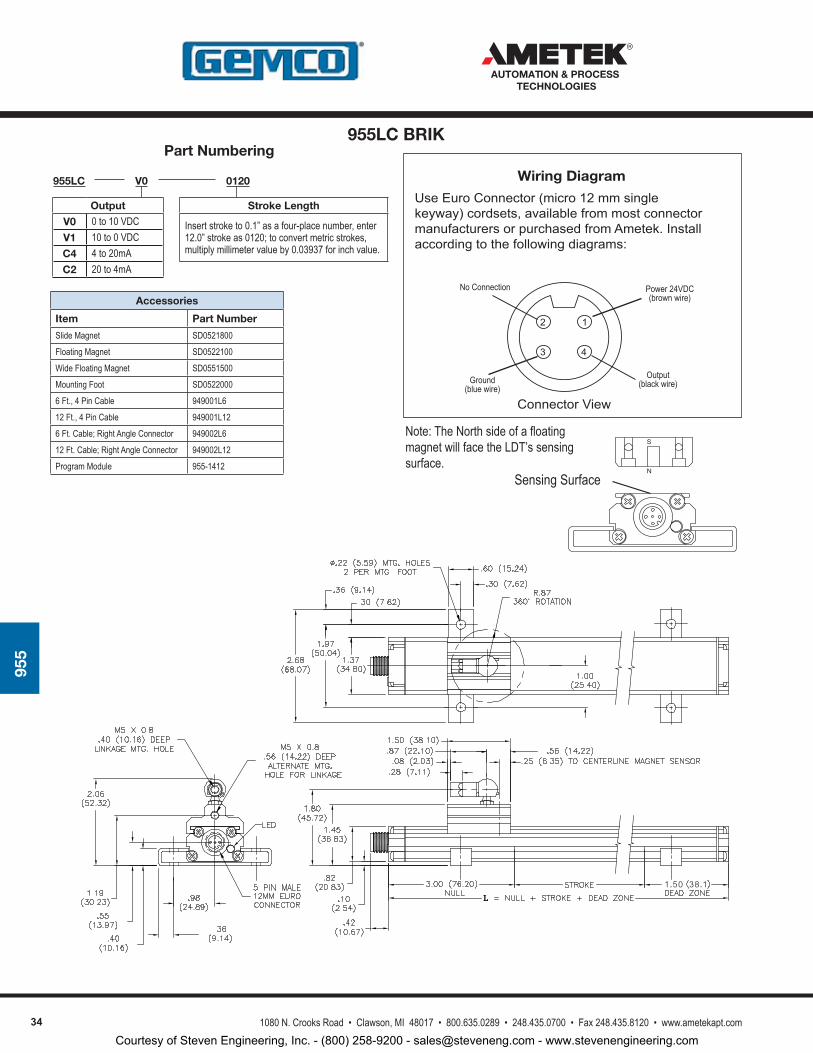
34 1080 N. Crooks Road • Clawson, MI 48017 • 800.635.0289 • 248.435.0700 • Fax 248.435.8120 • www.ametekapt.com
AUTOMATION & PROCESS TECHNOLOGIES
955
Part Numbering
Accessories
Item Part Number
Slide Magnet SD0521800
Floating Magnet SD0522100
Wide Floating Magnet SD0551500
Mounting Foot SD0522000
6 Ft., 4 Pin Cable 949001L6
12 Ft., 4 Pin Cable 949001L12
6 Ft. Cable; Right Angle Connector 949002L6
12 Ft. Cable; Right Angle Connector 949002L12
Program Module 955-1412
UseEuroConnector(micro12mmsinglekeyway)cordsets,availablefrommostconnectormanufacturersorpurchasedfromAmetek.Installaccordingtothefollowingdiagrams:
ConnectorView
Wiring Diagram
3
2
4
1
Power 24VDC(brown wire)
Output(black wire)Ground
(blue wire)
No Connection
955LC 0120V0
Stroke Length
Insert stroke to 0.1” as a four-place number, enter 12.0” stroke as 0120; to convert metric strokes, multiply millimeter value by 0.03937 for inch value.
Output
V0 0 to 10 VDCV1 10 to 0 VDCC4 4 to 20mAC2 20 to 4mA
Sensing SurfaceN
SNote: The North side of a floating magnet will face the LDT’s sensing surface.
955LC BRIK
Courtesy of Steven Engineering, Inc. - (800) 258-9200 - [email protected] - www.stevenengineering.com
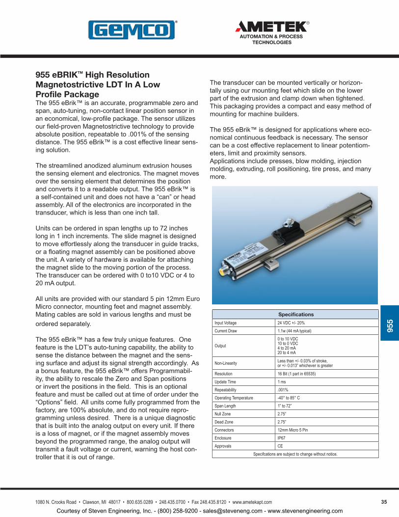
351080 N. Crooks Road • Clawson, MI 48017 • 800.635.0289 • 248.435.0700 • Fax 248.435.8120 • www.ametekapt.com
AUTOMATION & PROCESS TECHNOLOGIES
955
Thetransducercanbemountedverticallyorhorizon-tallyusingourmountingfeetwhichslideonthelowerpartoftheextrusionandclampdownwhentightened.Thispackagingprovidesacompactandeasymethodofmountingformachinebuilders.
The955eBrik™isdesignedforapplicationswhereeco-nomicalcontinuousfeedbackisnecessary.Thesensorcanbeacosteffectivereplacementtolinearpotentiom-eters,limitandproximitysensors.Applicationsincludepresses,blowmolding,injectionmolding,extruding,rollpositioning,tirepress,andmanymore.
955 eBRIKTM High Resolution Magnetostrictive LDT In A Low Profile PackageThe955eBrik™isanaccurate,programmablezeroandspan,auto-tuning,non-contactlinearpositionsensorinaneconomical,low-profilepackage.Thesensorutilizesourfield-provenMagnetostrictivetechnologytoprovideabsoluteposition,repeatableto.001%ofthesensingdistance.The955eBrik™isacosteffectivelinearsens-ingsolution.
Thestreamlinedanodizedaluminumextrusionhousesthesensingelementandelectronics.Themagnetmovesoverthesensingelementthatdeterminesthepositionandconvertsittoareadableoutput.The955eBrik™isaself-containedunitanddoesnothavea“can”orheadassembly.Alloftheelectronicsareincorporatedinthetransducer,whichislessthanoneinchtall.
Unitscanbeorderedinspanlengthsupto72incheslongin1inchincrements.Theslidemagnetisdesignedtomoveeffortlesslyalongthetransduceringuidetracks,orafloatingmagnetassemblycanbepositionedabovetheunit.Avarietyofhardwareisavailableforattachingthemagnetslidetothemovingportionoftheprocess.Thetransducercanbeorderedwith0to10VDCor4to20mAoutput.
Allunitsareprovidedwithourstandard5pin12mmEuroMicroconnector,mountingfeetandmagnetassembly.Matingcablesaresoldinvariouslengthsandmustbeorderedseparately.
The955eBrik™hasafewtrulyuniquefeatures.OnefeatureistheLDT’sauto-tuningcapability,theabilitytosensethedistancebetweenthemagnetandthesens-ingsurfaceandadjustitssignalstrengthaccordingly.Asabonusfeature,the955eBrik™offersProgrammabil-ity,theabilitytorescaletheZeroandSpanpositionsorinvertthepositionsinthefield.Thisisanoptionalfeatureandmustbecalledoutattimeoforderunderthe“Options”field.Allunitscomefullyprogrammedfromthefactory,are100%absolute,anddonotrequirerepro-grammingunlessdesired.Thereisauniquediagnosticthatisbuiltintotheanalogoutputoneveryunit.Ifthereisalossofmagnet,orifthemagnetassemblymovesbeyondtheprogrammedrange,theanalogoutputwilltransmitafaultvoltageorcurrent,warningthehostcon-trollerthatitisoutofrange.
Specifications
Input Voltage 24 VDC +/- 20%
Current Draw 1.1w (44 mA typical)
Output0 to 10 VDC10 to 0 VDC4 to 20 mA20 to 4 mA
Non-Linearity Less than +/- 0.03% of stroke, or +/- 0.013” whichever is greater
Resolution 16 Bit (1 part in 65535)
Update Time 1 ms
Repeatability .001%
Operating Temperature -40° to 85° C
Span Length 1” to 72”
Null Zone 2.75”
Dead Zone 2.75”
Connectors 12mm Micro 5 Pin
Enclosure IP67
Approvals CE
Specifcations are subject to change without notice.
Courtesy of Steven Engineering, Inc. - (800) 258-9200 - [email protected] - www.stevenengineering.com
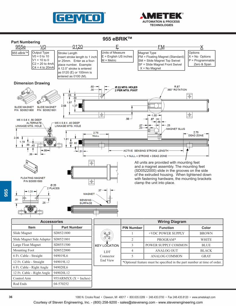
36 1080 N. Crooks Road • Clawson, MI 48017 • 800.635.0289 • 248.435.0700 • Fax 248.435.8120 • www.ametekapt.com
AUTOMATION & PROCESS TECHNOLOGIES
955
Allunitsareprovidedwithmountingfeetandamagnetassembly.Themountingfeet(SD0522000)slideinthegroovesonthesideoftheextrudedhousing.Whentighteneddownwithfasteninghardware,themountingbracketsclamptheunitintoplace.
955e955eBrik™ OutputType
V0=0to10V1=10to0C2=20to4mAC4=4to20mA
StrokeLengthInsertstrokelengthto1inchor25mm.Enterasafour-placenumber.Example:A12.0”strokeisenteredas0120(E)or100mmisenteredas0100(M).
UnitsofMeasureE=EnglishUSinchesM=Metric
MagnetTypeFM=FloatingMagnet(Standard)SM=SlideMagnetTopSwivelSF=SlideMagnetFrontSwivelX=NoMagnet
OptionsX=NoOptionsP=ProgrammableZero&Span
Part Numbering
Dimension Drawing
AccessoriesItem Part Number
Slide Magnet SD0521800
Slide Magnet Side Adapter SD0521801Large Float Magnet SD0551500Mounting Foot SD05220006 Ft. Cable - Straight 949019L6
12 Ft. Cable - Straight 949019L126 Ft. Cable - Right Angle 949020L612 Ft. Cable - Right Angle 949020L12Control Arm 955ARMXX (X = Inches)Rod Ends 04-570252
Wiring DiagramPIN Number Function Color
1 +VDC POWER SUPPLY BROWN
2 PROGRAM* WHITE3 POWER SUPPLY COMMON BLUE4 ANALOG OUT BLACK5 ANALOG COMMON GRAY
*Optional feature must be specified in the part number at time of order.
LDT Connector End View
V0 0120 E FM X
955 eBRIKTM
Courtesy of Steven Engineering, Inc. - (800) 258-9200 - [email protected] - www.stevenengineering.com
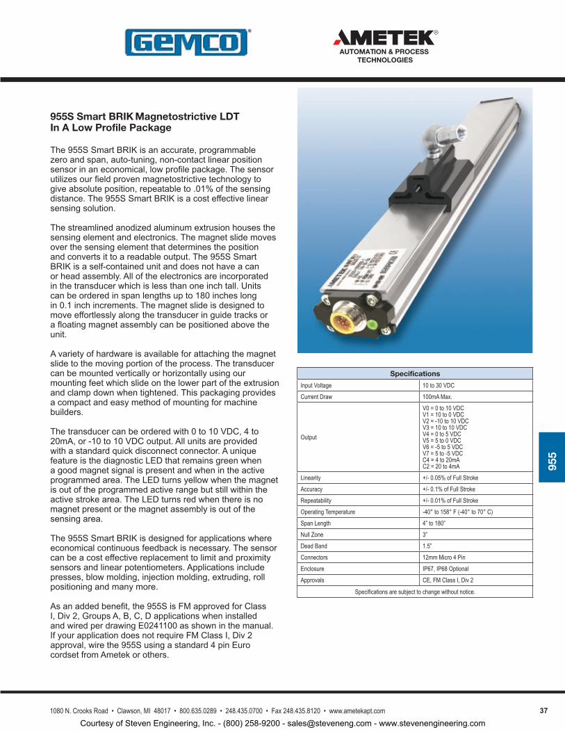
371080 N. Crooks Road • Clawson, MI 48017 • 800.635.0289 • 248.435.0700 • Fax 248.435.8120 • www.ametekapt.com
AUTOMATION & PROCESS TECHNOLOGIES
955
955S Smart BRIK Magnetostrictive LDT In A Low Profile Package
The955SSmartBRIKisanaccurate,programmablezeroandspan,auto-tuning,non-contactlinearpositionsensorinaneconomical,lowprofilepackage.Thesensorutilizesourfieldprovenmagnetostrictivetechnologytogiveabsoluteposition,repeatableto.01%ofthesensingdistance.The955SSmartBRIKisacosteffectivelinearsensingsolution.
Thestreamlinedanodizedaluminumextrusionhousesthesensingelementandelectronics.Themagnetslidemovesoverthesensingelementthatdeterminesthepositionandconvertsittoareadableoutput.The955SSmartBRIKisaself-containedunitanddoesnothaveacanorheadassembly.Alloftheelectronicsareincorporatedinthetransducerwhichislessthanoneinchtall.Unitscanbeorderedinspanlengthsupto180incheslongin0.1inchincrements.Themagnetslideisdesignedtomoveeffortlesslyalongthetransduceringuidetracksorafloatingmagnetassemblycanbepositionedabovetheunit.
Avarietyofhardwareisavailableforattachingthemagnetslidetothemovingportionoftheprocess.Thetransducercanbemountedverticallyorhorizontallyusingourmountingfeetwhichslideonthelowerpartoftheextrusionandclampdownwhentightened.Thispackagingprovidesacompactandeasymethodofmountingformachinebuilders.
Thetransducercanbeorderedwith0to10VDC,4to20mA,or-10to10VDCoutput.Allunitsareprovidedwithastandardquickdisconnectconnector.AuniquefeatureisthediagnosticLEDthatremainsgreenwhenagoodmagnetsignalispresentandwhenintheactiveprogrammedarea.TheLEDturnsyellowwhenthemagnetisoutoftheprogrammedactiverangebutstillwithintheactivestrokearea.TheLEDturnsredwhenthereisnomagnetpresentorthemagnetassemblyisoutofthesensingarea.
The955SSmartBRIKisdesignedforapplicationswhereeconomicalcontinuousfeedbackisnecessary.Thesensorcanbeacosteffectivereplacementtolimitandproximitysensorsandlinearpotentiometers.Applicationsincludepresses,blowmolding,injectionmolding,extruding,rollpositioningandmanymore.
Asanaddedbenefit,the955SisFMapprovedforClassI,Div2,GroupsA,B,C,DapplicationswheninstalledandwiredperdrawingE0241100asshowninthemanual.IfyourapplicationdoesnotrequireFMClassI,Div2approval,wirethe955Susingastandard4pinEurocordsetfromAmetekorothers.
Specifications
Input Voltage 10 to 30 VDC
Current Draw 100mA Max.
Output
V0 = 0 to 10 VDCV1 = 10 to 0 VDCV2 = -10 to 10 VDCV3 = 10 to 10 VDCV4 = 0 to 5 VDCV5 = 5 to 0 VDCV6 = -5 to 5 VDCV7 = 5 to -5 VDCC4 = 4 to 20mAC2 = 20 to 4mA
Linearity +/- 0.05% of Full Stroke
Accuracy +/- 0.1% of Full Stroke
Repeatability +/- 0.01% of Full Stroke
Operating Temperature -40° to 158° F (-40° to 70° C)
Span Length 4” to 180”
Null Zone 3”
Dead Band 1.5”
Connectors 12mm Micro 4 Pin
Enclosure IP67, IP68 Optional
Approvals CE, FM Class I, Div 2
Specifications are subject to change without notice.
Courtesy of Steven Engineering, Inc. - (800) 258-9200 - [email protected] - www.stevenengineering.com
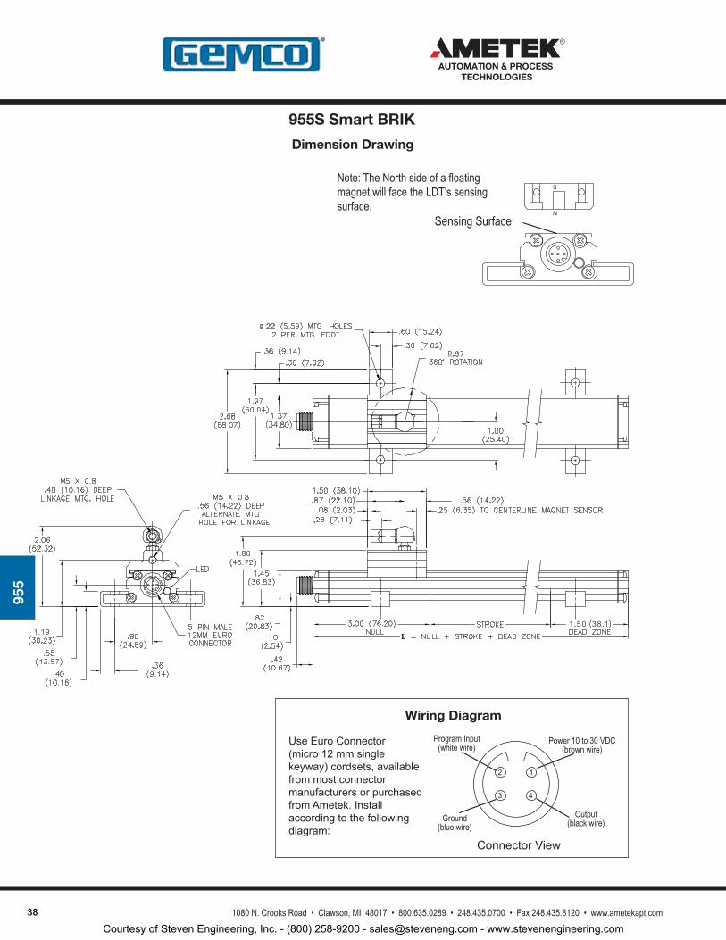
38 1080 N. Crooks Road • Clawson, MI 48017 • 800.635.0289 • 248.435.0700 • Fax 248.435.8120 • www.ametekapt.com
AUTOMATION & PROCESS TECHNOLOGIES
955
Dimension Drawing
ConnectorView
UseEuroConnector(micro12mmsinglekeyway)cordsets,availablefrommostconnectormanufacturersorpurchasedfromAmetek.Installaccordingtothefollowingdiagram:
Wiring Diagram
3
2
4
1
Power 10 to 30 VDC(brown wire)
Output(black wire)Ground
(blue wire)
Program Input(white wire)
Sensing SurfaceN
SNote: The North side of a floating magnet will face the LDT’s sensing surface.
955S Smart BRIK
Courtesy of Steven Engineering, Inc. - (800) 258-9200 - [email protected] - www.stevenengineering.com
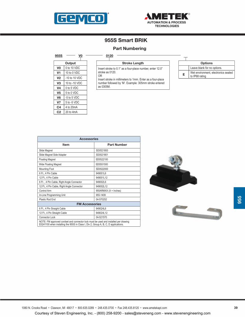
391080 N. Crooks Road • Clawson, MI 48017 • 800.635.0289 • 248.435.0700 • Fax 248.435.8120 • www.ametekapt.com
AUTOMATION & PROCESS TECHNOLOGIES
955
Accessories
Item Part Number
Slide Magnet SD0521800Slide Magnet Side Adapter SD0521801Floating Magnet SD0522100
Wide Floating Magnet SD0551500Mounting Foot SD05220006 Ft., 4 Pin Cable 949001L612 Ft., 4 Pin Cable 949001L126 Ft. , 4 Pin Cable, Right Angle Connector 949002L612 Ft., 4 Pin Cable, Right Angle Connector 949002L12Control Arm 955ARMXX (X = Inches)In-Line Programming Unit 955-1409Plastic Rod End 04-570252
FM Accessories6 Ft., 4 Pin Straight Cable 949024L612 Ft., 4 Pin Straight Cable 949024L12Connector Lock 04-521570NOTE: FM approved cordset and connector lock must be used and installed per drawing E0241100 when installing the 955S in Class I, Div 2, Group A, B, C, D applications.
Part Numbering
955S 0120V0
Output
V0 0 to 10 VDCV1 10 to 0 VDCV2 -10 to 10 VDCV3 10 to -10 VDCV4 0 to 5 VDCV5 5 to 0 VDCV6 -5 to 5 VDCV7 5 to -5 VDCC4 4 to 20mAC2 20 to 4mA
V0
OptionsLeave blank for no options.
E Wet environment, electronics sealed to IP68 rating
Stroke Length
Insert stroke to 0.1” as a four-place number, enter 12.0” stroke as 0120.ORInsert stroke in millimeters to 1mm. Enter as a four-place number followed by ‘M’. Example: 305mm stroke entered as 0305M.
955S Smart BRIK
Courtesy of Steven Engineering, Inc. - (800) 258-9200 - [email protected] - www.stevenengineering.com
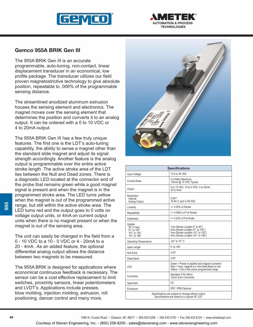
40 1080 N. Crooks Road • Clawson, MI 48017 • 800.635.0289 • 248.435.0700 • Fax 248.435.8120 • www.ametekapt.com
AUTOMATION & PROCESS TECHNOLOGIES
955
Specifications
Input Voltage 13.5 to 30 VDC
Current Draw 2.5 Watts Maximum, 120mA @ 15 VDC Typical
Output 0 to 10 VDC, 10 to 0 VDC, 4 to 20mA, 20 to 4mA
Resolution Internal Analog Output
0.001”16 Bit (1 part in 65,535)
Linearity +/- 0.05% of Stroke
Repeatbility +/- 0.006% of Full Stroke
Hysteresis +/- 0.02% of Full Scale
Update 50” or less 51” to 100” 101” to 150” 151” to 180”
1ms (Stroke Lengths 5” to 50”)2ms (Stroke Lengths 51” to 100”)3ms (Stroke Lengths 101” to 150”)4ms (Stroke Lengths 151” to 180”)
Operating Temperature -20° to 70° C
Span Length 5” to 180”
Null Zone 3.00”
Dead Band 2.00”
LEDGreen = Power is applied and magnet is presentRed = Fault, magnet is in the Dead Band or lostYellow = Out of the active programmed range
Connector Standard 5 Pin Micro 12mm Euro Connector
Approvals CE
Enclosure IP67, IP68 Optional
Specifications are subject to change without notice.Specifications are based on a typical 36” LDT.
Gemco 955A BRIK Gen III
The955ABRIKGenIIIisanaccurateprogrammable,auto-tuning,non-contact,lineardisplacementtransducerinaneconomical,lowprofilepackage.Thetransducerutilizesourfieldprovenmagnetostrictivetechnologytogiveabsoluteposition,repeatableto.006%oftheprogrammablesensingdistance.
Thestreamlinedanodizedaluminumextrusionhousesthesensingelementandelectronics.Themagnetmovesoverthesensingelementthatdeterminesthepositionandconvertsittoananalogoutput.Itcanbeorderedwitha0to10VDCor4to20mAoutput.
The955ABRIKGenIIIhasafewtrulyuniquefeatures.ThefirstoneistheLDT’sauto-tuningcapability,theabilitytosenseamagnetotherthanthestandardslidemagnetandadjustitssignalstrengthaccordingly.Anotherfeatureistheanalogoutputisprogrammableovertheentireactivestrokelength.TheactivestrokeareaoftheLDTliesbetweentheNullandDeadzones.ThereisadiagnosticLEDlocatedattheconnectorendoftheprobethatremainsgreenwhileagoodmagnetsignalispresentandwhenthemagnetisintheprogrammedstrokearea.TheLEDturnsyellowwhenthemagnetisoutoftheprogrammedactiverange,butstillwithintheactivestrokearea.TheLEDturnsredandtheoutputgoesto0voltsonvoltageoutputunits,or4mAoncurrentoutputunitswhenthereisnomagnetpresentorwhenthemagnetisoutofthesensingarea.
Theunitcaneasilybechangedinthefieldfroma0-10VDCtoa10-0VDCor4-20mAtoa20-4mA.Asanaddedfeature,theoptionaldifferentialanalogoutputallowsthedistancebetweentwomagnetstobemeasured.
The955ABRIKisdesignedforapplicationswhereeconomicalcontinuousfeedbackisnecessary.Thesensorcanbeacosteffectivereplacementtolimitswitches,proximitysensors,linearpotentiometersandLVDT’s.Applicationsincludepresses,blowmolding,injectionmolding,extrusion,rollpositioning,dancercontrolandmanymore.
Courtesy of Steven Engineering, Inc. - (800) 258-9200 - [email protected] - www.stevenengineering.com
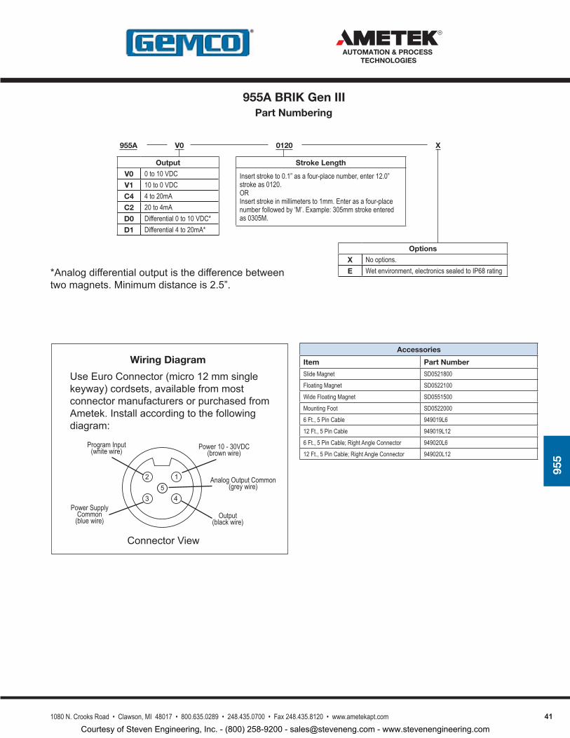
411080 N. Crooks Road • Clawson, MI 48017 • 800.635.0289 • 248.435.0700 • Fax 248.435.8120 • www.ametekapt.com
AUTOMATION & PROCESS TECHNOLOGIES
955
Accessories
Item Part Number
Slide Magnet SD0521800
Floating Magnet SD0522100
Wide Floating Magnet SD0551500
Mounting Foot SD0522000
6 Ft., 5 Pin Cable 949019L6
12 Ft., 5 Pin Cable 949019L12
6 Ft., 5 Pin Cable; Right Angle Connector 949020L6
12 Ft., 5 Pin Cable; Right Angle Connector 949020L12
ConnectorView
UseEuroConnector(micro12mmsinglekeyway)cordsets,availablefrommostconnectormanufacturersorpurchasedfromAmetek.Installaccordingtothefollowingdiagram:
Wiring Diagram
3
2
4
1
Power 10 - 30VDC(brown wire)
Output(black wire)
Power Supply Common
(blue wire)
Program Input(white wire)
5Analog Output Common
(grey wire)
Part Numbering
955A 0120V0
Stroke Length
Insert stroke to 0.1” as a four-place number, enter 12.0” stroke as 0120.ORInsert stroke in millimeters to 1mm. Enter as a four-place number followed by ‘M’. Example: 305mm stroke entered as 0305M.
Output
V0 0 to 10 VDCV1 10 to 0 VDCC4 4 to 20mAC2 20 to 4mA D0 Differential 0 to 10 VDC*D1 Differential 4 to 20mA*
X
Options
X No options.E Wet environment, electronics sealed to IP68 rating*Analogdifferentialoutputisthedifferencebetween
twomagnets.Minimumdistanceis2.5”.
955A BRIK Gen III
Courtesy of Steven Engineering, Inc. - (800) 258-9200 - [email protected] - www.stevenengineering.com

42 1080 N. Crooks Road • Clawson, MI 48017 • 800.635.0289 • 248.435.0700 • Fax 248.435.8120 • www.ametekapt.com
AUTOMATION & PROCESS TECHNOLOGIES
955
Specifications
Input Voltage 13.5 to 30 VDC
Current Draw 2.5 Watts Maximum, 120mA @ 15 VDC Typical
Output Control Pulse, Variable Pulse, Stop/Start
Resolution Controller Dependent
Linearity +/- 0.05% of Stroke
Repeatbility +/- 0.006% of Full Stroke
Hysteresis +/- 0.02% of Full Scale
Update Controller Dependent
Operating Temperature -20° to 70° C
Span Length 5” to 180”
Null Zone 3.00”
Dead Band 2.00”
LEDGreen = Power is applied and magnet is presentRed = Fault, magnet is in the Dead Band or lostYellow = No interrogation signal
Connector Standard 6 Pin Micro 12mm Euro Connector
Approvals CE
Enclosure IP67, IP68 Optional
Specifications are subject to change without notice.Specifications are based on a typical 36” LDT.
Gemco 955D Digital BRIK Gen III
The955DDigitalBRIKGenIIIisanaccurateprogrammable,auto-tuning,non-contact,lineardisplacementtransducerinaneconomical,lowprofilepackage.Thetransducerutilizesourfieldprovenmagnetostrictivetechnologytogiveabsoluteposition,repeatableto.006%oftheprogrammablesensingdistance.
Thestreamlinedanodizedaluminumextrusionhousesthesensingelementandelectronics.Themagnetmovesoverthesensingelementthatdeterminesthepositionandconvertsittoeitheracontrolpulse,variablepulseorRS422Start/Stopdigitaloutput.The955DiscompatiblewithPLCInterfaceCardslikeour2120L1moduleand1746LTDInterfaceCard.
The955DBRIKGenIIIhassometrulyuniquefeatures.ThefirstoneistheLDT’sauto-tuningcapability,theabilitytosenseamagnetotherthanthestandardslidemagnetandadjustitssignalstrengthaccordingly.
ThereisadiagnosticLEDlocatedattheconnectorendoftheprobethatremainsgreenwhileagoodmagnetsignalispresentandwhenthemagnetisintheprogrammedstrokearea.TheLEDturnsyellowifnointerrogationsignalisdetected.TheLEDturnsredwhenthereisnomagnetpresentorwhenthemagnetisoutofthesensingarea.
The955DBRIKisdesignedforapplicationswhereeconomicalcontinuousfeedbackisnecessary.Thesensorcanbeacosteffectivereplacementtolimitswitches,proximitysensors,linearpotentiometersandLVDT’s.Applicationsincludepresses,blowmolding,injectionmolding,extrusion,rollpositioning,dancercontrolandmanymore.
Courtesy of Steven Engineering, Inc. - (800) 258-9200 - [email protected] - www.stevenengineering.com
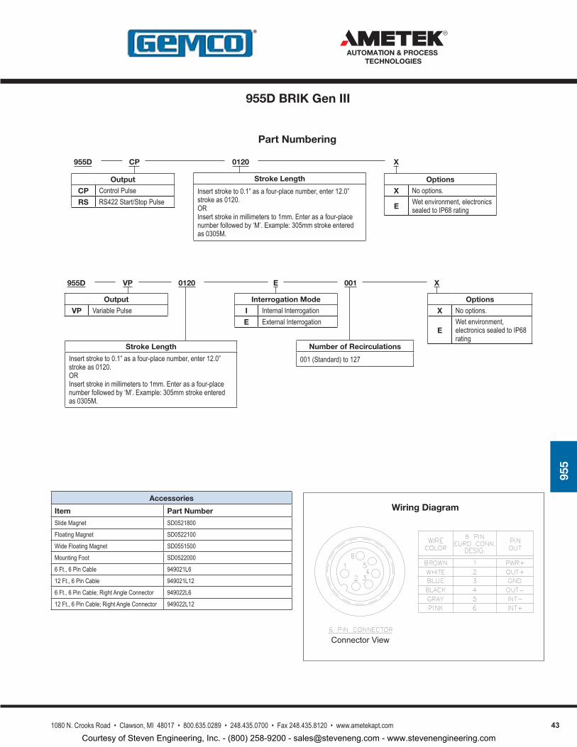
431080 N. Crooks Road • Clawson, MI 48017 • 800.635.0289 • 248.435.0700 • Fax 248.435.8120 • www.ametekapt.com
AUTOMATION & PROCESS TECHNOLOGIES
955
Accessories
Item Part Number
Slide Magnet SD0521800
Floating Magnet SD0522100
Wide Floating Magnet SD0551500
Mounting Foot SD0522000
6 Ft., 6 Pin Cable 949021L6
12 Ft., 6 Pin Cable 949021L12
6 Ft., 6 Pin Cable; Right Angle Connector 949022L6
12 Ft., 6 Pin Cable; Right Angle Connector 949022L12
Part Numbering
955D 0120CP
Output
CP Control PulseRS RS422 Start/Stop Pulse
X
Options
X No options.
E Wet environment, electronics sealed to IP68 rating
Wiring Diagram
ConnectorView
955D 0120VP
Output
VP Variable Pulse
X
Options
X No options.
EWet environment, electronics sealed to IP68 rating
001
Number of Recirculations
001 (Standard) to 127
E
Interrogation Mode
I Internal InterrogationE External Interrogation
Stroke Length
Insert stroke to 0.1” as a four-place number, enter 12.0” stroke as 0120.ORInsert stroke in millimeters to 1mm. Enter as a four-place number followed by ‘M’. Example: 305mm stroke entered as 0305M.
Stroke Length
Insert stroke to 0.1” as a four-place number, enter 12.0” stroke as 0120.ORInsert stroke in millimeters to 1mm. Enter as a four-place number followed by ‘M’. Example: 305mm stroke entered as 0305M.
955D BRIK Gen III
Courtesy of Steven Engineering, Inc. - (800) 258-9200 - [email protected] - www.stevenengineering.com
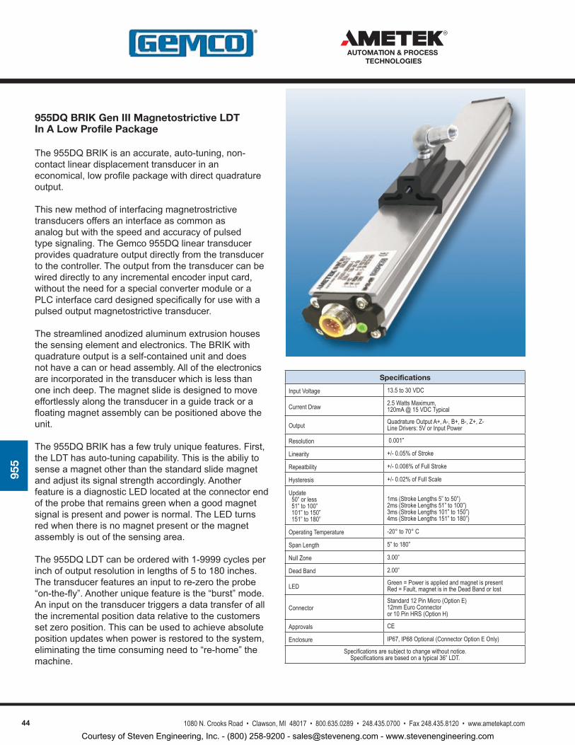
44 1080 N. Crooks Road • Clawson, MI 48017 • 800.635.0289 • 248.435.0700 • Fax 248.435.8120 • www.ametekapt.com
AUTOMATION & PROCESS TECHNOLOGIES
955
955DQ BRIK Gen III Magnetostrictive LDT In A Low Profile Package
The955DQBRIKisanaccurate,auto-tuning,non-contactlineardisplacementtransducerinaneconomical,lowprofilepackagewithdirectquadratureoutput.
Thisnewmethodofinterfacingmagnetrostrictivetransducersoffersaninterfaceascommonasanalogbutwiththespeedandaccuracyofpulsedtypesignaling.TheGemco955DQlineartransducerprovidesquadratureoutputdirectlyfromthetransducertothecontroller.Theoutputfromthetransducercanbewireddirectlytoanyincrementalencoderinputcard,withouttheneedforaspecialconvertermoduleoraPLCinterfacecarddesignedspecificallyforusewithapulsedoutputmagnetostrictivetransducer.
Thestreamlinedanodizedaluminumextrusionhousesthesensingelementandelectronics.TheBRIKwithquadratureoutputisaself-containedunitanddoesnothaveacanorheadassembly.Alloftheelectronicsareincorporatedinthetransducerwhichislessthanoneinchdeep.Themagnetslideisdesignedtomoveeffortlesslyalongthetransducerinaguidetrackorafloatingmagnetassemblycanbepositionedabovetheunit.
The955DQBRIKhasafewtrulyuniquefeatures.First,theLDThasauto-tuningcapability.Thisistheabiliytosenseamagnetotherthanthestandardslidemagnetandadjustitssignalstrengthaccordingly.AnotherfeatureisadiagnosticLEDlocatedattheconnectorendoftheprobethatremainsgreenwhenagoodmagnetsignalispresentandpowerisnormal.TheLEDturnsredwhenthereisnomagnetpresentorthemagnetassemblyisoutofthesensingarea.
The955DQLDTcanbeorderedwith1-9999cyclesperinchofoutputresolutioninlengthsof5to180inches.Thetransducerfeaturesaninputtore-zerotheprobe“on-the-fly”.Anotheruniquefeatureisthe“burst”mode.Aninputonthetransducertriggersadatatransferofalltheincrementalpositiondatarelativetothecustomerssetzeroposition.Thiscanbeusedtoachieveabsolutepositionupdateswhenpowerisrestoredtothesystem,eliminatingthetimeconsumingneedto“re-home”themachine.
Specifications
Input Voltage 13.5 to 30 VDC
Current Draw 2.5 Watts Maximum, 120mA @ 15 VDC Typical
Output Quadrature Output A+, A-, B+, B-, Z+, Z- Line Drivers: 5V or Input Power
Resolution 0.001”
Linearity +/- 0.05% of Stroke
Repeatbility +/- 0.006% of Full Stroke
Hysteresis +/- 0.02% of Full Scale
Update 50” or less 51” to 100” 101” to 150” 151” to 180”
1ms (Stroke Lengths 5” to 50”)2ms (Stroke Lengths 51” to 100”)3ms (Stroke Lengths 101” to 150”)4ms (Stroke Lengths 151” to 180”)
Operating Temperature -20° to 70° C
Span Length 5” to 180”
Null Zone 3.00”
Dead Band 2.00”
LED Green = Power is applied and magnet is presentRed = Fault, magnet is in the Dead Band or lost
Connector Standard 12 Pin Micro (Option E)12mm Euro Connectoror 10 Pin HRS (Option H)
Approvals CE
Enclosure IP67, IP68 Optional (Connector Option E Only)
Specifications are subject to change without notice.Specifications are based on a typical 36” LDT.
Courtesy of Steven Engineering, Inc. - (800) 258-9200 - [email protected] - www.stevenengineering.com
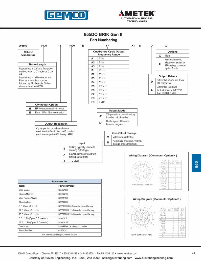
451080 N. Crooks Road • Clawson, MI 48017 • 800.635.0289 • 248.435.0700 • Fax 248.435.8120 • www.ametekapt.com
AUTOMATION & PROCESS TECHNOLOGIES
955
Accessories
Item Part Number
Slide Magnet SD0521800
Floating Magnet SD0522100
Wide Floating Magnet SD0551500
Mounting Foot SD0522000
6 Ft. Cable (Option H) SD0527700L6 - Obsolete, consult factory
12 Ft. Cable (Option H) SD0527700L12 - Obsolete, consult factory
25 Ft. Cable (Option H) SD0527700L25 - Obsolete, consult factory
6 Ft. 12 Pin (Option E Connector ) 949023L6
12 Ft. 12 Pin (Option E Connector) 949023L12
Control Arm 955ARMXX ( X = Length in Inches )
Plastic Rod End 04-570252
For non-standard lengths, consult factory. 12 PIN CONNECTOR VIEW
Wiring Diagram ( Connector Option E )
Wiring Diagram ( Connector Option H )
10 PIN HIROSE CONNECTOR VIEW
Part Numbering 955DQ 0120 E
Connector Option
H HRS environmental connectorE Euro 12 Pin, 12mm connector
955DQ Quadrature
1000
Output Resolution
Cycles per inch, maximum internal resolution is 0.001 inches 1000 standard (available range is 0001 through 9999)
X1F7E
Input
E Sinking (typically used with sourcing output type)
C Sourcing (typically used with sinking output type)
T TTL Level
Output Mode
X1 X1 quadrature, consult factory for other output modes
D1 Dual magnet, difference between magnets
Quadrature Cycle Output Frequency Range
A1 1 kHzA2 2 kHzA3 5 kHzF1 10 kHzF2 25 kHzF3 50 kHzF4 75 kHzF5 100 kHzF6 150 kHzF7 250 kHzF8 500 kHzF9 1 MHz
N XD
Output Drivers
D Differential RS422 line driver, TTL compatible
LDifferential line driver 10 to 30 VDC, V out = V in (LDT Power) -1 Volt
Options
X None
E
Wet environment, electronics sealed to IP68 rating, connector option E only
Zero Offset Storage
V Volatile (non retentive)
N Nonvolatile (retentive, 100,000 storage cycles maximum)
Stroke Length
Insert stroke to 0.1” as a four-place number, enter 12.0” stroke as 0120.ORInsert stroke in millimeters to 1mm. Enter as a four-place number followed by ‘M’. Example: 305mm stroke entered as 0305M.
955DQ BRIK Gen III
Courtesy of Steven Engineering, Inc. - (800) 258-9200 - [email protected] - www.stevenengineering.com
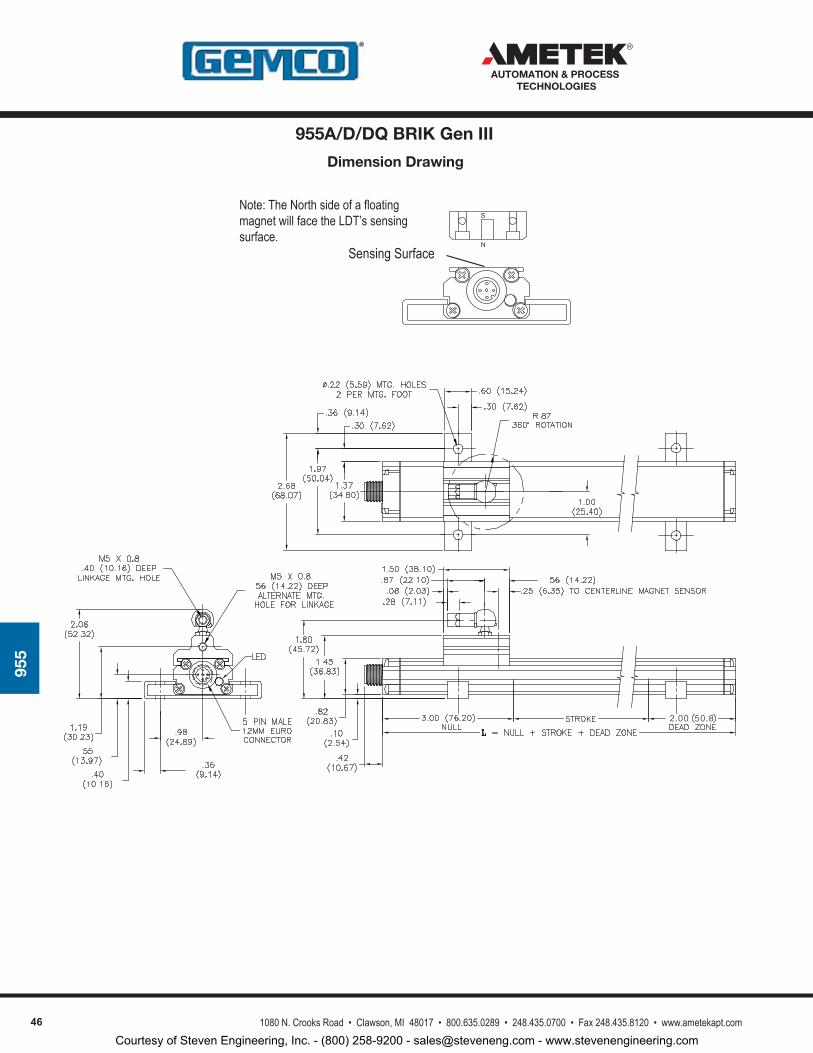
46 1080 N. Crooks Road • Clawson, MI 48017 • 800.635.0289 • 248.435.0700 • Fax 248.435.8120 • www.ametekapt.com
AUTOMATION & PROCESS TECHNOLOGIES
955
Dimension Drawing
Sensing SurfaceN
SNote: The North side of a floating magnet will face the LDT’s sensing surface.
955A/D/DQ BRIK Gen III
Courtesy of Steven Engineering, Inc. - (800) 258-9200 - [email protected] - www.stevenengineering.com
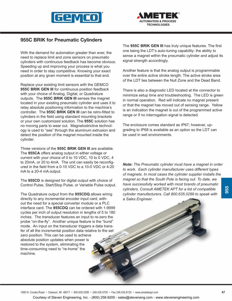
471080 N. Crooks Road • Clawson, MI 48017 • 800.635.0289 • 248.435.0700 • Fax 248.435.8120 • www.ametekapt.com
AUTOMATION & PROCESS TECHNOLOGIES
955
Withthedemandforautomationgreaterthanever,theneedtoreplacelimitandzonesensorsonpneumaticcylinderswithcontinuousfeedbackhasbecomeobvious.Speedingupandimprovingyourprocessiswhatyouneedinordertostaycompetitive.Knowingyourexactpositionatanygivenmomentisessentialtothatend.
ReplaceyourexistinglimitsensorswiththeGEMCO955CBRIK GEN IIIforcontinuouspositionfeedbackwithyourchoiceofAnalog,Digital,orQuadratureoutputs.The955CBRIK GEN III sensesthemagnetlocatedinyourexistingpneumaticcylinderandusesittorelayabsolutepositioninginformationtothemachine’scontroller.The955C BRIKGEN IIIcanberetro-fittedtocylindersinthefieldusingstandardmountingbracketsoryourowncustomizedsolution.The955Csolutionhasnomovingpartstowearout.Magnetostrictivetechnol-ogyisusedto“see”throughthealuminumextrusionanddetectthepositionofthemagnetmountedinsidethecylinder.
Threeversionsofthe 955C BRIK GEN III areavailable.The955CAoffersanalogoutputineithervoltageorcurrentwithyourchoiceof0to10VDC,10to0VDC,4to20mA,or20to4mA.Theunitcaneasilybereconfig-uredinthefieldfroma0-10VDCtoa10-0VDCor4-20mAtoa20-4mAoutput.
The 955CDisdesignedfordigitaloutputwithchoiceofControlPulse,Start/StopPulse,orVariablePulseoutput.
TheQuadratureoutputfromthe955CDQallowswiringdirectlytoanyincrementalencoderinputcard,with-outtheneedforaspecialconvertermoduleoraPLCinterfacecard.The955CDQcanbeorderedwith1-9999cyclesperinchofoutputresolutioninlengthsof5to180inches.Thetransducerfeaturesaninputtore-zerotheprobe“on-the-fly”.Anotheruniquefeatureisthe“burst”mode.Aninputonthetransducertriggersadatatrans-ferofalltheincrementalpositiondatarelativetothesetzeroposition.Thiscanbeusedtoachieveabsolutepositionupdateswhenpowerisrestoredtothesystem,eliminatingthetime-consumingneedto“re-home”themachine.
The 955C BRIK GEN III hastrulyuniquefeatures.ThefirstonebeingtheLDT’sauto-tuningcapability:theabilitytosenseamagnetwithinthepneumaticcylinderandadjustitssignalstrengthaccordingly.
Anotherfeatureisthattheanalogoutputisprogrammableovertheentireactivestrokelength.TheactivestrokeareaoftheLDTliesbetweentheNullZoneandtheDeadBand.
ThereisalsoadiagnosticLEDlocatedattheconnectortominimizesetuptimeandtroubleshooting.TheLEDisgreeninnormaloperation.Redwillindicatenomagnetpresentorthatthemagnethasmovedoutofsensingrange.Yellowisanindicationthemagnetisoutoftheprogrammedactiverangeorifnointerrogationsignalisdetected.
TheenclosurecomesstandardasIP67;however,up-gradingtoIP68isavailableasanoptionsotheLDTcanbeusedinwetenvironments.
Note: The Pneumatic cylinder must have a magnet in order to work. Each cylinder manufacturer uses different types of magnets. In most cases the cylinder supplier installs the magnet so that the South Pole is facing out. To date, we have successfully worked with most brands of pneumatic cylinders. Consult AMETEK APT for a list of compatible cylinder manufacturers. Call 800.635.0289 to speak with a Sales Engineer.
955C BRIK for Pneumatic Cylinders
Courtesy of Steven Engineering, Inc. - (800) 258-9200 - [email protected] - www.stevenengineering.com
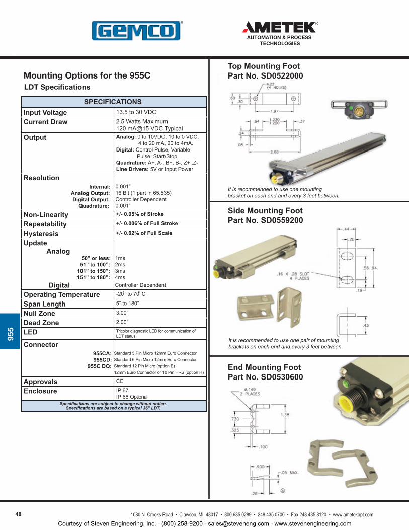
48 1080 N. Crooks Road • Clawson, MI 48017 • 800.635.0289 • 248.435.0700 • Fax 248.435.8120 • www.ametekapt.com
AUTOMATION & PROCESS TECHNOLOGIES
955
Input Voltage 13.5to30VDC
Current Draw 2.5WattsMaximum,120mA@15VDCTypical
Output Analog:0to10VDC,10to0VDC,4to20mA,20to4mA.Digital:ControlPulse,VariablePulse,Start/StopQuadrature:A+,A-,B+,B-,Z+,Z-Line Drivers:5VorInputPower
Resolution Internal: Analog Output: Digital Output: Quadrature:
Non-Linearity +/- 0.05% of Stroke
Repeatability +/- 0.006% of Full Stroke
Hysteresis +/- 0.02% of Full Scale
Update Analog 50” or less: 51” to 100”: 101” to 150”: 151” to 180”: DigitalOperating Temperature -20to70C
Span Length 5”to180”
Null Zone 3.00”
Dead Zone 2.00”
LED TricolordiagnosticLEDforcommunicationofLDTstatus.
Connector 955CA: 955CD: 955C DQ:
Approvals CE
Enclosure IP67IP68Optional
0.001”16Bit(1partin65,535)ControllerDependent0.001”
1ms2ms3ms4msControllerDependent
Specifications are subject to change without notice. Specifications are based on a typical 36” LDT.
SPECIFICATIONS
o o
Standard5PinMicro12mmEuroConnectorStandard6PinMicro12mmEuroConnectorStandard12PinMicro(optionE)12mmEuroConnectoror10PinHRS(optionH)
LDT Specifications
It is recommended to use one mounting bracket on each end and every 3 feet between.
It is recommended to use one pair of mounting brackets on each end and every 3 feet between.
Side Mounting FootPart No. SD0559200
End Mounting FootPart No. SD0530600
Top Mounting FootPart No. SD0522000Mounting Options for the 955C
Courtesy of Steven Engineering, Inc. - (800) 258-9200 - [email protected] - www.stevenengineering.com
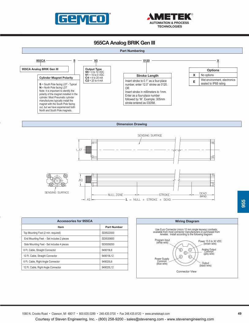
491080 N. Crooks Road • Clawson, MI 48017 • 800.635.0289 • 248.435.0700 • Fax 248.435.8120 • www.ametekapt.com
AUTOMATION & PROCESS TECHNOLOGIES
955
Accessories for 955CA
Item Part Number
Top Mounting Foot (2 min. required) SD0522000
End Mounting Feet - Set includes 2 pieces SD0530600
Side Mounting Feet - Set includes 4 pieces SD0559200
6 Ft. Cable, Straight Connector 949019L6
12 Ft. Cable, Straight Connector 949019L12
6 Ft. Cable, Right Angle Connector 949020L6
12 Ft. Cable, Right Angle Connector 949020L12
Wiring Diagram
ConnectorView
Use Euro Connector (micro 12 mm single keyway) cordsets, available from most connector manufacturers or purchased from
Ametek. Install according to the following diagram:
3
2
4
1
Power 13.5 to 30 VDC(brown wire)
Output(black wire)
Power Supply Common
(blue wire)
Program Input(white wire)
5Analog Output
Common(grey wire)
955CA V0S 0120 X
955CA Analog BRIK Gen III Output Type V0 = 0 to 10 VDCV1 = 10 to 0 VDCC4 = 4 to 20 mAC2 = 20 to 4 mA
Part Numbering
Dimension Drawing
955CA Analog BRIK Gen III
Options
X No options
E Wet environment, electronics sealed to IP68 rating
Stroke Length
Insert stroke to 0.1” as a four-place number, enter 12.0” stroke as 0120.ORInsert stroke in millimeters to 1mm. Enter as a four-place number followed by ‘M’. Example: 305mm stroke entered as 0305M.
Cylinder Magnet Polarity
S = South Pole facing LDT - TypicalN = North Pole facing LDTNote: It is important to identify the polarity of the magnet installed in the cylinder. Most Pneumatic cylinder manufactures typically install the magnet with the South Pole facing out, but we have experienced both North and South Pole magnets.
Courtesy of Steven Engineering, Inc. - (800) 258-9200 - [email protected] - www.stevenengineering.com
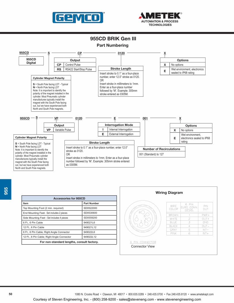
50 1080 N. Crooks Road • Clawson, MI 48017 • 800.635.0289 • 248.435.0700 • Fax 248.435.8120 • www.ametekapt.com
AUTOMATION & PROCESS TECHNOLOGIES
955
Cylinder Magnet Polarity
S = South Pole facing LDT - TypicalN = North Pole facing LDTNote: It is important to identify the polarity of the magnet installed in the cylinder. Most Pneumatic cylinder manufactures typically install the magnet with the South Pole facing out, but we have experienced both North and South Pole magnets.
955CD
955CD Digital
955CD BRIK Gen III Part Numbering
0120CPS
S
Output
CP Control PulseRS RS422 Start/Stop Pulse
X
Options
X No options
E Wet environment, electronics sealed to IP68 rating
Wiring Diagram
ConnectorView
955CD 0120VP
Output
VP Variable Pulse
X
Options
X No options
EWet environment, electronics sealed to IP68 rating
001
Number of Recirculations
001 (Standard) to 127
E
Interrogation Mode
I Internal InterrogationE External Interrogation
Stroke Length
Insert stroke to 0.1” as a four-place number, enter 12.0” stroke as 0120.ORInsert stroke in millimeters to 1mm. Enter as a four-place number followed by ‘M’. Example: 305mm stroke entered as 0305M.
Item Part Number
TopMountingFoot(2min.required) SD0522000
EndMountingFeet- Set includes 2 pieces SD0530600
SideMountingFeet- Set includes 4 pieces SD0559200
6Ft.,6PinCable 949021L6
12Ft.,6PinCable 949021L12
6Ft.,6PinCable;RightAngleConnector 949022L6
12Ft.,6PinCable;RightAngleConnector 949022L12
For non-standard lengths, consult factory.
Accessories for 955CD
Stroke Length
Insert stroke to 0.1” as a four-place number, enter 12.0” stroke as 0120.ORInsert stroke in millimeters to 1mm. Enter as a four-place number followed by ‘M’. Example: 305mm stroke entered as 0305M.
Cylinder Magnet Polarity
S = South Pole facing LDT - TypicalN = North Pole facing LDTNote: It is important to identify the polarity of the magnet installed in the cylinder. Most Pneumatic cylinder manufactures typically install the magnet with the South Pole facing out, but we have experienced both North and South Pole magnets.
Courtesy of Steven Engineering, Inc. - (800) 258-9200 - [email protected] - www.stevenengineering.com
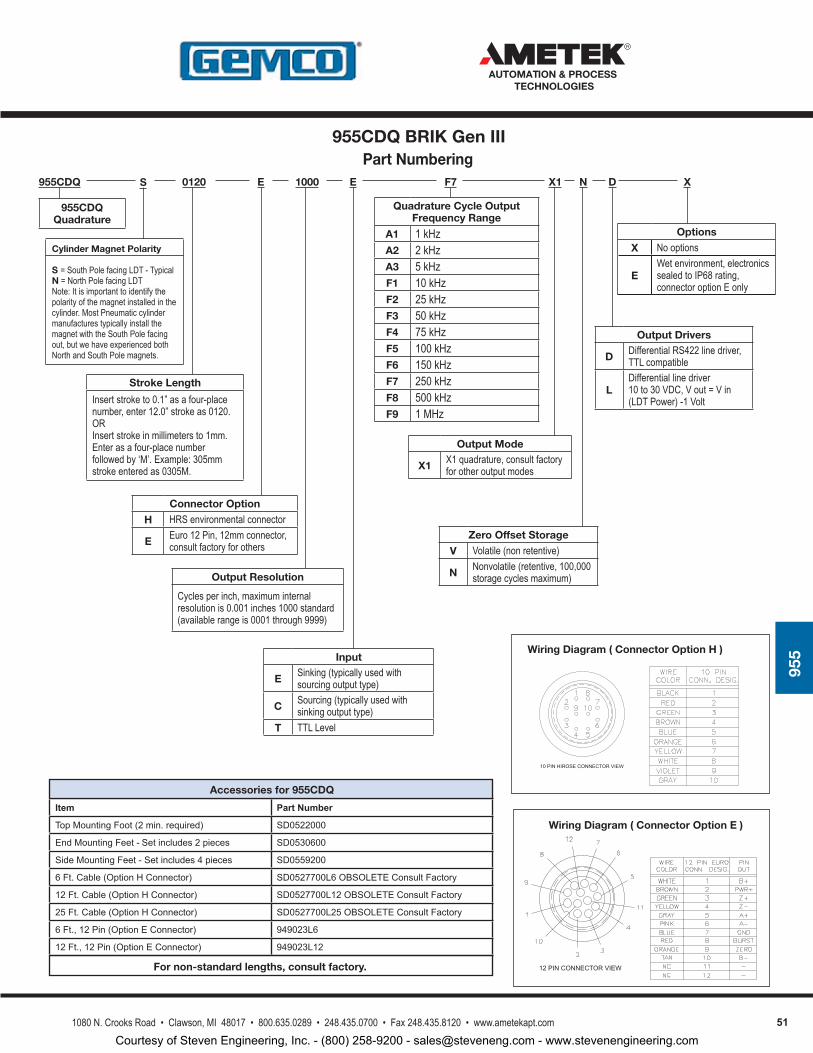
511080 N. Crooks Road • Clawson, MI 48017 • 800.635.0289 • 248.435.0700 • Fax 248.435.8120 • www.ametekapt.com
AUTOMATION & PROCESS TECHNOLOGIES
955
12 PIN CONNECTOR VIEW
Wiring Diagram ( Connector Option E )
Wiring Diagram ( Connector Option H )
10 PIN HIROSE CONNECTOR VIEW
Part Numbering 955CDQ 0120S E
Connector Option
H HRS environmental connector
E Euro 12 Pin, 12mm connector, consult factory for others
955CDQ Quadrature
1000
Output Resolution
Cycles per inch, maximum internal resolution is 0.001 inches 1000 standard (available range is 0001 through 9999)
X1F7E
Input
E Sinking (typically used with sourcing output type)
C Sourcing (typically used with sinking output type)
T TTL Level
Output Mode
X1 X1 quadrature, consult factory for other output modes
Quadrature Cycle Output Frequency Range
A1 1 kHzA2 2 kHzA3 5 kHzF1 10 kHzF2 25 kHzF3 50 kHzF4 75 kHzF5 100 kHzF6 150 kHzF7 250 kHzF8 500 kHzF9 1 MHz
N XD
Output Drivers
D Differential RS422 line driver, TTL compatible
LDifferential line driver 10 to 30 VDC, V out = V in (LDT Power) -1 Volt
Zero Offset Storage
V Volatile (non retentive)
N Nonvolatile (retentive, 100,000 storage cycles maximum)
Stroke Length
Insert stroke to 0.1” as a four-place number, enter 12.0” stroke as 0120.ORInsert stroke in millimeters to 1mm. Enter as a four-place number followed by ‘M’. Example: 305mm stroke entered as 0305M.
Item Part Number
TopMountingFoot(2min.required) SD0522000
EndMountingFeet- Setincludes2pieces SD0530600
SideMountingFeet-Setincludes4pieces SD0559200
6Ft.Cable(OptionHConnector) SD0527700L6OBSOLETEConsultFactory
12Ft.Cable(OptionHConnector) SD0527700L12OBSOLETEConsultFactory
25Ft.Cable(OptionHConnector) SD0527700L25OBSOLETEConsultFactory
6Ft.,12Pin(OptionEConnector) 949023L6
12Ft.,12Pin(OptionEConnector) 949023L12
Accessories for 955CDQ
For non-standard lengths, consult factory.
Options
X No options
EWet environment, electronics sealed to IP68 rating,connector option E only
Cylinder Magnet Polarity
S = South Pole facing LDT - TypicalN = North Pole facing LDTNote: It is important to identify the polarity of the magnet installed in the cylinder. Most Pneumatic cylinder manufactures typically install the magnet with the South Pole facing out, but we have experienced both North and South Pole magnets.
955CDQ BRIK Gen III
Courtesy of Steven Engineering, Inc. - (800) 258-9200 - [email protected] - www.stevenengineering.com
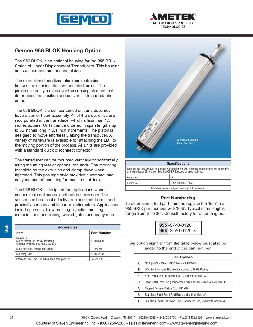
52 1080 N. Crooks Road • Clawson, MI 48017 • 800.635.0289 • 248.435.0700 • Fax 248.435.8120 • www.ametekapt.com
AUTOMATION & PROCESS TECHNOLOGIES
956
Gemco 956 BLOK Housing Option
The956BLOKisanoptionalhousingforthe955BRIKSeriesofLinearDisplacementTransducers.Thishousingaddsachamber,magnetandpiston.
Thestreamlinedanodizedaluminumextrusionhousesthesensingelementandelectronics.Thepistonassemblymovesoverthesensingelementthatdeterminesthepositionandconvertsittoareadableoutput.
The956BLOKisaself-containedunitanddoesnothaveacanorheadassembly.Alloftheelectronicsareincorporatedinthetransducerwhichislessthan1.5inchessquare.Unitscanbeorderedinspanlengthsupto36incheslongin0.1inchincrements.Thepistonisdesignedtomoveeffortlesslyalongthetransducer.AvarietyofhardwareisavailableforattachingtheLDTtothemovingportionoftheprocess.Allunitsareprovidedwithastandardquickdisconnectconector.
Thetransducercanbemountedverticallyorhorizontallyusingmountingfeetoroptionalrodends.Themountingfeetslideontheextrusionandclampdownwhentightened.Thispackagestyleprovidesacompactandeasymethodofmountingformachinebuilders.
The956BLOKisdesignedforapplicationswhereeconomicalcontinuousfeedbackisnecessary.Thesensorcanbeacosteffectivereplacementtolimitandproximitysensorsandlinearpotentiometers.Applicationsincludepresses,blowmolding,injectionmolding,extrusion,rollpositioning,wicketgatesandmanymore.
Accessories
Item Part Number
Spacer Kit Mount feet for .45” or .75” mounting Includes two mounting feet & spacers
SD0545100
Metal Rod End, Female for Option”F” 04-570256
Mounting Foot SD0522000
Stainless Steel Rod End 1/4-28 Male for Option ”A” 04-570264
Specifications
Because the 956 BLOK is an optional housing for the 955, electrical specifications are dependant on the particular 955 sensor. See the 955 BRIK pages for specifications.
Approvals CE
Enclosure IP67 (Optional IP68)
Specifications are subject to change without notice.
Shown with optional Metal Rod End.
Part NumberingTodeterminea956partnumber,replacethe‘955’ina955BRIKpartnumberwith‘956’.Typicalspanlengthsrangefrom6”to36”.Consultfactoryforotherlengths.
Anoptionsignifierfromthetablebelowmustalsobeaddedtotheendofthepartnumber.
955-S-V0-0120956-S-V0-0120-X
956 Options
X No Options - Male Piston 1/4” - 28 Threads.
E Wet Environment. Electronics sealed to IP 68 Rating.
F Front Metal Rod End, Female - used with option “X”.
R Rear Metal Rod End (Connector End), Female - used with option “X”.
A Tapped Female Piston Rod 1/4” -28 .
S Stainless Steel Front Rod End used with option “A”.
T Stainless Steel Rear Rod End (Connector End) used with option “A”.
Courtesy of Steven Engineering, Inc. - (800) 258-9200 - [email protected] - www.stevenengineering.com
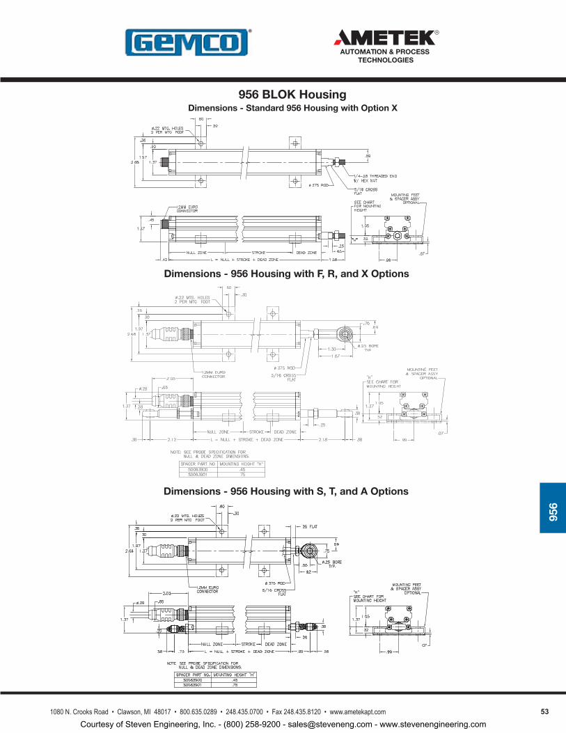
531080 N. Crooks Road • Clawson, MI 48017 • 800.635.0289 • 248.435.0700 • Fax 248.435.8120 • www.ametekapt.com
AUTOMATION & PROCESS TECHNOLOGIES
956
Dimensions - Standard 956 Housing with Option X956 BLOK Housing
Dimensions - 956 Housing with F, R, and X Options
Dimensions - 956 Housing with S, T, and A Options
Courtesy of Steven Engineering, Inc. - (800) 258-9200 - [email protected] - www.stevenengineering.com
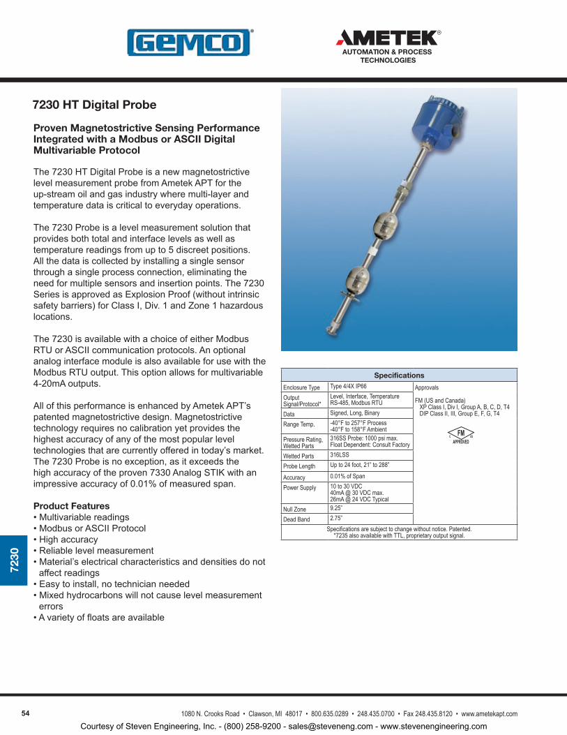
54 1080 N. Crooks Road • Clawson, MI 48017 • 800.635.0289 • 248.435.0700 • Fax 248.435.8120 • www.ametekapt.com
AUTOMATION & PROCESS TECHNOLOGIES
7230
Specifications
Enclosure Type Type 4/4X IP66 Approvals
FM (US and Canada) XP Class I, Div I, Group A, B, C, D, T4 DIP Class II, III, Group E, F, G, T4
Output Signal/Protocol*
Level, Interface, TemperatureRS-485, Modbus RTU
Data Signed, Long, Binary
Range Temp. -40°F to 257°F Process-40°F to 158°F Ambient
Pressure Rating, Wetted Parts
316SS Probe: 1000 psi max.Float Dependent: Consult Factory
Wetted Parts 316LSS
Probe Length Up to 24 foot, 21” to 288”
Accuracy 0.01% of Span
Power Supply 10 to 30 VDC 40mA @ 30 VDC max.26mA @ 24 VDC Typical
Null Zone 9.25”
Dead Band 2.75”Specifications are subject to change without notice. Patented.
*7235 also available with TTL, proprietary output signal.
APPROVEDC USFM
Proven Magnetostrictive Sensing Performance Integrated with a Modbus or ASCII Digital Multivariable Protocol
The7230HTDigitalProbeisanewmagnetostrictivelevelmeasurementprobefromAmetekAPTfortheup-streamoilandgasindustrywheremulti-layerandtemperaturedataiscriticaltoeverydayoperations.
The7230Probeisalevelmeasurementsolutionthatprovidesbothtotalandinterfacelevelsaswellastemperaturereadingsfromupto5discreetpositions.Allthedataiscollectedbyinstallingasinglesensorthroughasingleprocessconnection,eliminatingtheneedformultiplesensorsandinsertionpoints.The7230SeriesisapprovedasExplosionProof(withoutintrinsicsafetybarriers)forClassI,Div.1andZone1hazardouslocations.
The7230isavailablewithachoiceofeitherModbusRTUorASCIIcommunicationprotocols.AnoptionalanaloginterfacemoduleisalsoavailableforusewiththeModbusRTUoutput.Thisoptionallowsformultivariable4-20mAoutputs.
AllofthisperformanceisenhancedbyAmetekAPT’spatentedmagnetostrictivedesign.Magnetostrictivetechnologyrequiresnocalibrationyetprovidesthehighestaccuracyofanyofthemostpopularleveltechnologiesthatarecurrentlyofferedintoday’smarket.The7230Probeisnoexception,asitexceedsthehighaccuracyoftheproven7330AnalogSTIKwithanimpressiveaccuracyof0.01%ofmeasuredspan.
Product Features•Multivariablereadings•ModbusorASCIIProtocol•Highaccuracy•Reliablelevelmeasurement•Material’selectricalcharacteristicsanddensitiesdonotaffectreadings
•Easytoinstall,notechnicianneeded•Mixedhydrocarbonswillnotcauselevelmeasurementerrors
•Avarietyoffloatsareavailable
7230 HT Digital Probe
Courtesy of Steven Engineering, Inc. - (800) 258-9200 - [email protected] - www.stevenengineering.com
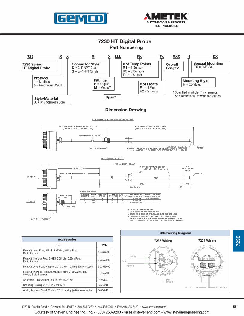
551080 N. Crooks Road • Clawson, MI 48017 • 800.635.0289 • 248.435.0700 • Fax 248.435.8120 • www.ametekapt.com
AUTOMATION & PROCESS TECHNOLOGIES
7230
723 X X X X LLL Fx XXX H EX
Overall Length*
Mounting StyleH = Condulet
Connector StyleD = 3/4” NPT DualS = 3/4” NPT Single
Fittings E = EnglishM = Metric**
7230 Series HT Digital Probe
Protocol1 = Modbus 5 = Proprietary ASCII
Span*
# of FloatsF1 = 1 FloatF2 = 2 Floats
Special MountingEX = FM/CSA
Style/MaterialX = 316 Stainless Steel
* Specified in whole 1” increments. See Dimension Drawing for ranges.
Rx
# of Temp PointsR1 = 1 SensorR5 = 5 SensorsT1 = 1 Sensor
Dimension Drawing
Part Numbering
7230 Wiring Diagram
7235 Wiring 7231 WiringAccessories
Item P/N
Float Kit: Level Float, 316SS, 2.05” dia., 0.54sg Float, E-clip & spacer SD0557200
Float Kit: Interface Float, 316SS, 2.05” dia., 0.96sg Float, E-clip & spacer SD0556800
Float Kit: Level Float, Nitrophyl 2.0” d x 3.0” h 0.40sg, E-clip & spacer SD0548600
Float Kit: Interface Float (w/Nitro. level float), 316SS, 2.05” dia., 0.96sg, E-clip & spacer SD0557300
Adjustable Tube Coupling: 316SS, 5/8” x 3/4” NPT 04283800
Reducing Bushing: 316SS, 2” x 3/4” NPT 04587241
Analog Interface Board: Modbus RTU to analog (4-20mA) converter 04534047
DA
TAP
WR
CO
M
7230 HT Digital Probe
Courtesy of Steven Engineering, Inc. - (800) 258-9200 - [email protected] - www.stevenengineering.com
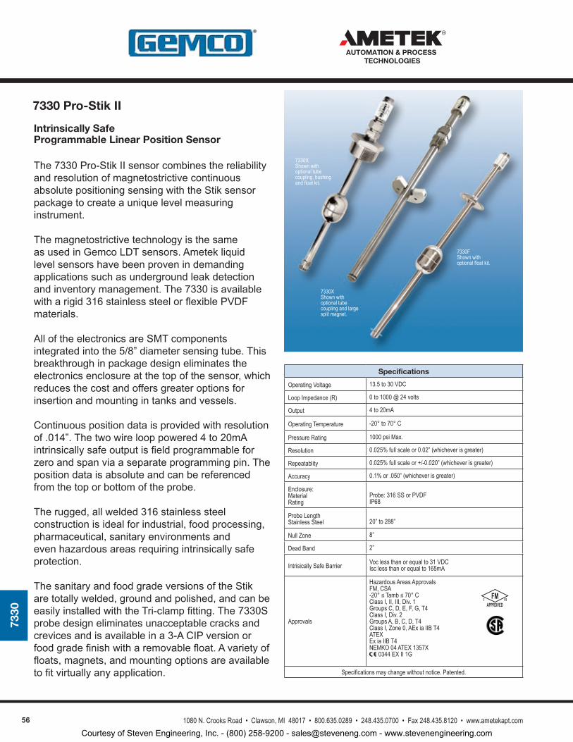
56 1080 N. Crooks Road • Clawson, MI 48017 • 800.635.0289 • 248.435.0700 • Fax 248.435.8120 • www.ametekapt.com
AUTOMATION & PROCESS TECHNOLOGIES
7330
Intrinsically Safe Programmable Linear Position Sensor
The7330Pro-StikIIsensorcombinesthereliabilityandresolutionofmagnetostrictivecontinuousabsolutepositioningsensingwiththeStiksensorpackagetocreateauniquelevelmeasuringinstrument.
ThemagnetostrictivetechnologyisthesameasusedinGemcoLDTsensors.Ametekliquidlevelsensorshavebeenprovenindemandingapplicationssuchasundergroundleakdetectionandinventorymanagement.The7330isavailablewitharigid316stainlesssteelorflexiblePVDFmaterials.
AlloftheelectronicsareSMTcomponentsintegratedintothe5/8”diametersensingtube.Thisbreakthroughinpackagedesigneliminatestheelectronicsenclosureatthetopofthesensor,whichreducesthecostandoffersgreateroptionsforinsertionandmountingintanksandvessels.
Continuouspositiondataisprovidedwithresolutionof.014”.Thetwowirelooppowered4to20mAintrinsicallysafeoutputisfieldprogrammableforzeroandspanviaaseparateprogrammingpin.Thepositiondataisabsoluteandcanbereferencedfromthetoporbottomoftheprobe.
Therugged,allwelded316stainlesssteelconstructionisidealforindustrial,foodprocessing,pharmaceutical,sanitaryenvironmentsandevenhazardousareasrequiringintrinsicallysafeprotection.
ThesanitaryandfoodgradeversionsoftheStikaretotallywelded,groundandpolished,andcanbeeasilyinstalledwiththeTri-clampfitting.The7330Sprobedesigneliminatesunacceptablecracksandcrevicesandisavailableina3-ACIPversionorfoodgradefinishwitharemovablefloat.Avarietyoffloats,magnets,andmountingoptionsareavailabletofitvirtuallyanyapplication.
Specifications
Operating Voltage 13.5 to 30 VDC
Loop Impedance (R) 0 to 1000 @ 24 volts
Output 4 to 20mA
Operating Temperature -20° to 70° C
Pressure Rating 1000 psi Max.
Resolution 0.025% full scale or 0.02” (whichever is greater)
Repeatablity 0.025% full scale or +/-0.020” (whichever is greater)
Accuracy 0.1% or .050” (whichever is greater)
Enclosure:MaterialRating
Probe: 316 SS or PVDFIP68
Probe LengthStainless Steel 20” to 288”
Null Zone 8”
Dead Band 2”
Intrisically Safe Barrier Voc less than or equal to 31 VDCIsc less than or equal to 165mA
Approvals
Hazardous Areas ApprovalsFM, CSA-20° ≤ Tamb ≤ 70° CClass I, II, III, Div. 1Groups C, D, E, F, G, T4Class I, Div. 2Groups A, B, C, D, T4Class I, Zone 0, AEx ia IIB T4ATEXEx ia IIB T4NEMKO 04 ATEX 1357X 0344 EX II 1G
Specifications may change without notice. Patented.
7330FShown with optional float kit.
7330X Shown with optional tube coupling, bushing and float kit.
7330XShown with optional tube coupling and large split magnet.
7330 Pro-Stik II
APPROVEDC USFM
Courtesy of Steven Engineering, Inc. - (800) 258-9200 - [email protected] - www.stevenengineering.com
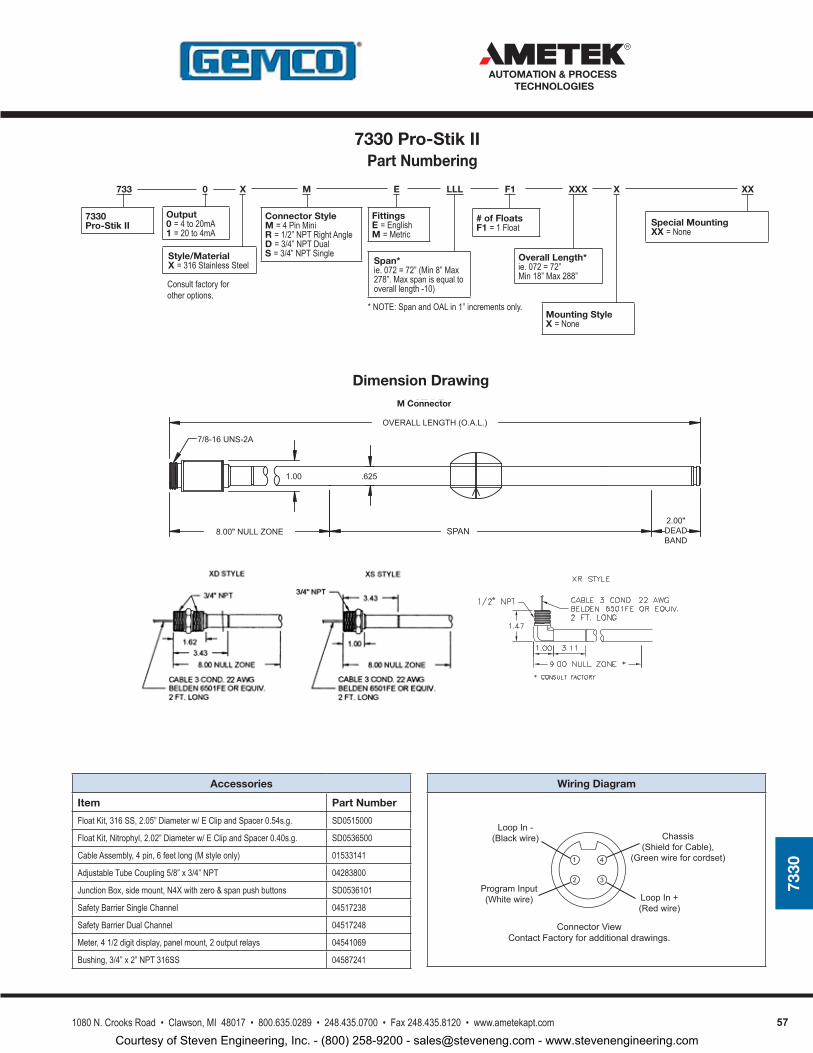
571080 N. Crooks Road • Clawson, MI 48017 • 800.635.0289 • 248.435.0700 • Fax 248.435.8120 • www.ametekapt.com
AUTOMATION & PROCESS TECHNOLOGIES
7330
Accessories
Item Part Number
Float Kit, 316 SS, 2.05” Diameter w/ E Clip and Spacer 0.54s.g. SD0515000
Float Kit, Nitrophyl, 2.02” Diameter w/ E Clip and Spacer 0.40s.g. SD0536500
Cable Assembly, 4 pin, 6 feet long (M style only) 01533141
Adjustable Tube Coupling 5/8” x 3/4” NPT 04283800
Junction Box, side mount, N4X with zero & span push buttons SD0536101
Safety Barrier Single Channel 04517238
Safety Barrier Dual Channel 04517248
Meter, 4 1/2 digit display, panel mount, 2 output relays 04541069
Bushing, 3/4” x 2” NPT 316SS 04587241
Wiring Diagram
733 0 X M E LLL F1 XXX X XX
Overall Length*ie. 072 = 72” Min 18” Max 288”
Mounting StyleX = None
Connector StyleM = 4 Pin MiniR = 1/2” NPT Right AngleD = 3/4” NPT DualS = 3/4” NPT Single
Fittings E = EnglishM = Metric
7330 Pro-Stik II
Output0 = 4 to 20mA1 = 20 to 4mA
Span*ie. 072 = 72” (Min 8” Max 278”. Max span is equal to overall length -10)
# of FloatsF1 = 1 Float Special Mounting
XX = None
Style/MaterialX = 316 Stainless Steel
Consult factory for other options.
Chassis(ShieldforCable),
(Greenwireforcordset)
LoopIn-(Blackwire)
ProgramInput(Whitewire) LoopIn+
(Redwire)
ConnectorViewContactFactoryforadditionaldrawings.
1
2
4
3
* NOTE: Span and OAL in 1” increments only.
7/8-16UNS-2A
1.00
8.00"NULLZONE
OVERALLLENGTH(O.A.L.)
.625
2.00"DEADBAND
MSTYLEM Connector
SPAN
Dimension Drawing
Part Numbering7330 Pro-Stik II
Courtesy of Steven Engineering, Inc. - (800) 258-9200 - [email protected] - www.stevenengineering.com
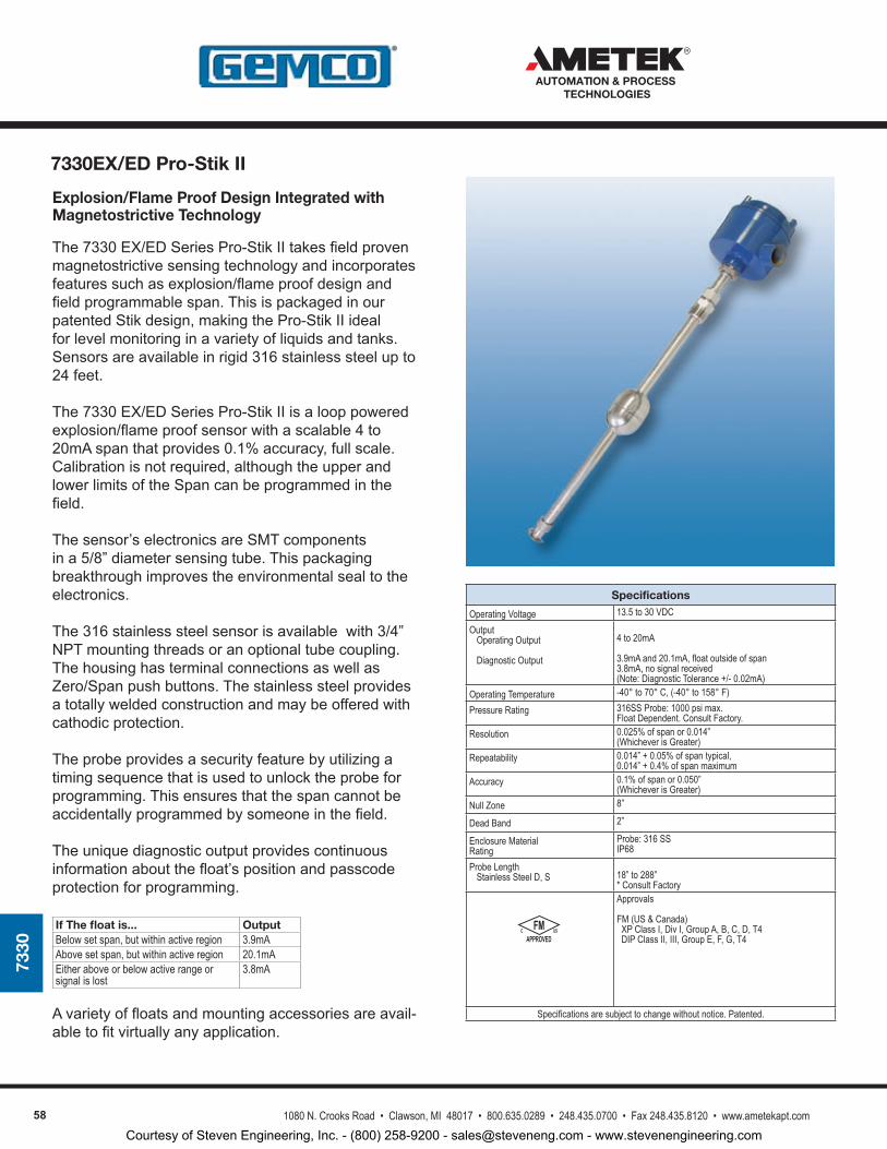
58 1080 N. Crooks Road • Clawson, MI 48017 • 800.635.0289 • 248.435.0700 • Fax 248.435.8120 • www.ametekapt.com
AUTOMATION & PROCESS TECHNOLOGIES
7330
Explosion/Flame Proof Design Integrated with Magnetostrictive Technology
The7330EX/EDSeriesPro-StikIItakesfieldprovenmagnetostrictivesensingtechnologyandincorporatesfeaturessuchasexplosion/flameproofdesignandfieldprogrammablespan.ThisispackagedinourpatentedStikdesign,makingthePro-StikIIidealforlevelmonitoringinavarietyofliquidsandtanks.Sensorsareavailableinrigid316stainlesssteelupto24feet.
The7330EX/EDSeriesPro-StikIIisalooppoweredexplosion/flameproofsensorwithascalable4to20mAspanthatprovides0.1%accuracy,fullscale.Calibrationisnotrequired,althoughtheupperandlowerlimitsoftheSpancanbeprogrammedinthefield.
Thesensor’selectronicsareSMTcomponentsina5/8”diametersensingtube.Thispackagingbreakthroughimprovestheenvironmentalsealtotheelectronics.
The316stainlesssteelsensorisavailablewith3/4”NPTmountingthreadsoranoptionaltubecoupling.ThehousinghasterminalconnectionsaswellasZero/Spanpushbuttons.Thestainlesssteelprovidesatotallyweldedconstructionandmaybeofferedwithcathodicprotection.
Theprobeprovidesasecurityfeaturebyutilizingatimingsequencethatisusedtounlocktheprobeforprogramming.Thisensuresthatthespancannotbeaccidentallyprogrammedbysomeoneinthefield.
Theuniquediagnosticoutputprovidescontinuousinformationaboutthefloat’spositionandpasscodeprotectionforprogramming.
If The float is... OutputBelow set span, but within active region 3.9mAAbove set span, but within active region 20.1mAEither above or below active range or signal is lost
3.8mA
Avarietyoffloatsandmountingaccessoriesareavail-abletofitvirtuallyanyapplication.
Specifications
Operating Voltage 13.5 to 30 VDC
Output Operating Output
Diagnostic Output
4 to 20mA
3.9mA and 20.1mA, float outside of span3.8mA, no signal received(Note: Diagnostic Tolerance +/- 0.02mA)
Operating Temperature -40° to 70° C, (-40° to 158° F)
Pressure Rating 316SS Probe: 1000 psi max.Float Dependent. Consult Factory.
Resolution 0.025% of span or 0.014” (Whichever is Greater)
Repeatability 0.014” + 0.05% of span typical, 0.014” + 0.4% of span maximum
Accuracy 0.1% of span or 0.050” (Whichever is Greater)
Null Zone 8”
Dead Band 2”
Enclosure Material Rating
Probe: 316 SS IP68
Probe Length Stainless Steel D, S 18” to 288”
* Consult Factory
APPROVEDC USFM
Approvals
FM (US & Canada) XP Class I, Div I, Group A, B, C, D, T4 DIP Class II, III, Group E, F, G, T4
Specifications are subject to change without notice. Patented.
7330EX/ED Pro-Stik II
Courtesy of Steven Engineering, Inc. - (800) 258-9200 - [email protected] - www.stevenengineering.com
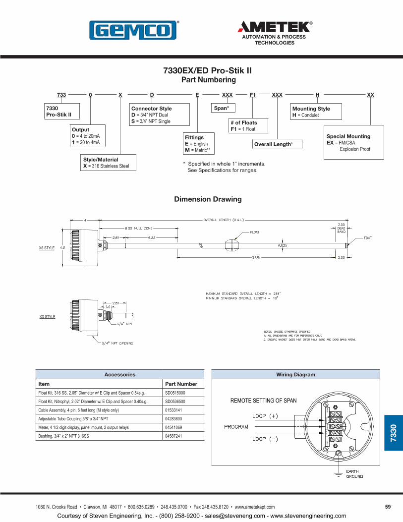
591080 N. Crooks Road • Clawson, MI 48017 • 800.635.0289 • 248.435.0700 • Fax 248.435.8120 • www.ametekapt.com
AUTOMATION & PROCESS TECHNOLOGIES
7330
Specifications
Operating Voltage 13.5 to 30 VDC
Output Operating Output
Diagnostic Output
4 to 20mA
3.9mA and 20.1mA, float outside of span3.8mA, no signal received(Note: Diagnostic Tolerance +/- 0.02mA)
Operating Temperature -40° to 70° C, (-40° to 158° F)
Pressure Rating 316SS Probe: 1000 psi max.Float Dependent. Consult Factory.
Resolution 0.025% of span or 0.014” (Whichever is Greater)
Repeatability 0.014” + 0.05% of span typical, 0.014” + 0.4% of span maximum
Accuracy 0.1% of span or 0.050” (Whichever is Greater)
Null Zone 8”
Dead Band 2”
Enclosure Material Rating
Probe: 316 SS IP68
Probe Length Stainless Steel D, S 18” to 288”
* Consult Factory
APPROVEDC USFM
Approvals
FM (US & Canada) XP Class I, Div I, Group A, B, C, D, T4 DIP Class II, III, Group E, F, G, T4
Specifications are subject to change without notice. Patented.
Accessories
Item Part Number
Float Kit, 316 SS, 2.05” Diameter w/ E Clip and Spacer 0.54s.g. SD0515000
Float Kit, Nitrophyl, 2.02” Diameter w/ E Clip and Spacer 0.40s.g. SD0536500
Cable Assembly, 4 pin, 6 feet long (M style only) 01533141
Adjustable Tube Coupling 5/8” x 3/4” NPT 04283800
Meter, 4 1/2 digit display, panel mount, 2 output relays 04541069
Bushing, 3/4” x 2” NPT 316SS 04587241
Wiring Diagram
733 0 X D E XXX F1 XXX H XX
Overall Length*
Mounting StyleH = Condulet
Connector StyleD = 3/4” NPT DualS = 3/4” NPT Single
Fittings E = EnglishM = Metric**
7330 Pro-Stik II
Output0 = 4 to 20mA1 = 20 to 4mA
Span*
# of FloatsF1 = 1 Float
Special MountingEX = FM/CSA Explosion Proof
Style/MaterialX = 316 Stainless Steel *Specifiedinwhole1”increments.
SeeSpecificationsforranges.
Dimension Drawing
Part Numbering
XS STYLE
XD STYLE
SPA
NZE
RO
LOO
P+
LOO
P-
PR
GM
REMOTE SETTING OF SPAN
7330EX/ED Pro-Stik II
Courtesy of Steven Engineering, Inc. - (800) 258-9200 - [email protected] - www.stevenengineering.com
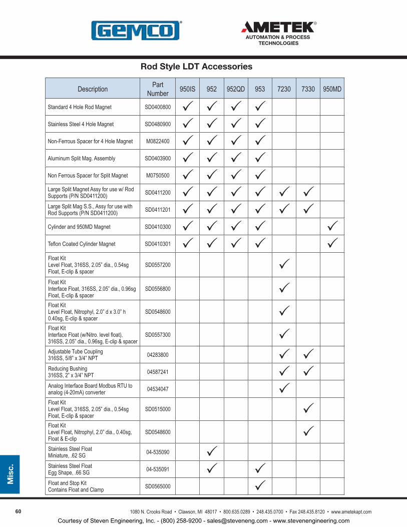
60 1080 N. Crooks Road • Clawson, MI 48017 • 800.635.0289 • 248.435.0700 • Fax 248.435.8120 • www.ametekapt.com
AUTOMATION & PROCESS TECHNOLOGIES
Mis
c.
Description Part Number 950IS 952 952QD 953 7230 7330 950MD
Standard 4 Hole Rod Magnet SD0400800 Stainless Steel 4 Hole Magnet SD0480900 Non-Ferrous Spacer for 4 Hole Magnet M0822400 Aluminum Split Mag. Assembly SD0403900 Non Ferrous Spacer for Split Magnet M0750500 Large Split Magnet Assy for use w/ Rod Supports (P/N SD0411200) SD0411200 Large Split Mag S.S., Assy for use with Rod Supports (P/N SD0411200) SD0411201 Cylinder and 950MD Magnet SD0410300 Teflon Coated Cylinder Magnet SD0410301 Float Kit Level Float, 316SS, 2.05” dia., 0.54sg Float, E-clip & spacer
SD0557200 Float Kit Interface Float, 316SS, 2.05” dia., 0.96sg Float, E-clip & spacer
SD0556800 Float Kit Level Float, Nitrophyl, 2.0” d x 3.0” h 0.40sg, E-clip & spacer
SD0548600 Float Kit Interface Float (w/Nitro. level float), 316SS, 2.05” dia., 0.96sg, E-clip & spacer
SD0557300 Adjustable Tube Coupling 316SS, 5/8” x 3/4” NPT 04283800 Reducing Bushing 316SS, 2” x 3/4” NPT 04587241 Analog Interface Board Modbus RTU to analog (4-20mA) converter 04534047 Float Kit Level Float, 316SS, 2.05” dia., 0.54sg Float, E-clip & spacer
SD0515000 Float Kit Level Float, Nitrophyl, 2.0” dia., 0.40sg, Float & E-clip
SD0548600 Stainless Steel Float Miniature, .62 SG 04-535090 Stainless Steel Float Egg Shape, .66 SG 04-535091 Float and Stop Kit Contains Float and Clamp SD0565000
Rod Style LDT Accessories
Courtesy of Steven Engineering, Inc. - (800) 258-9200 - [email protected] - www.stevenengineering.com
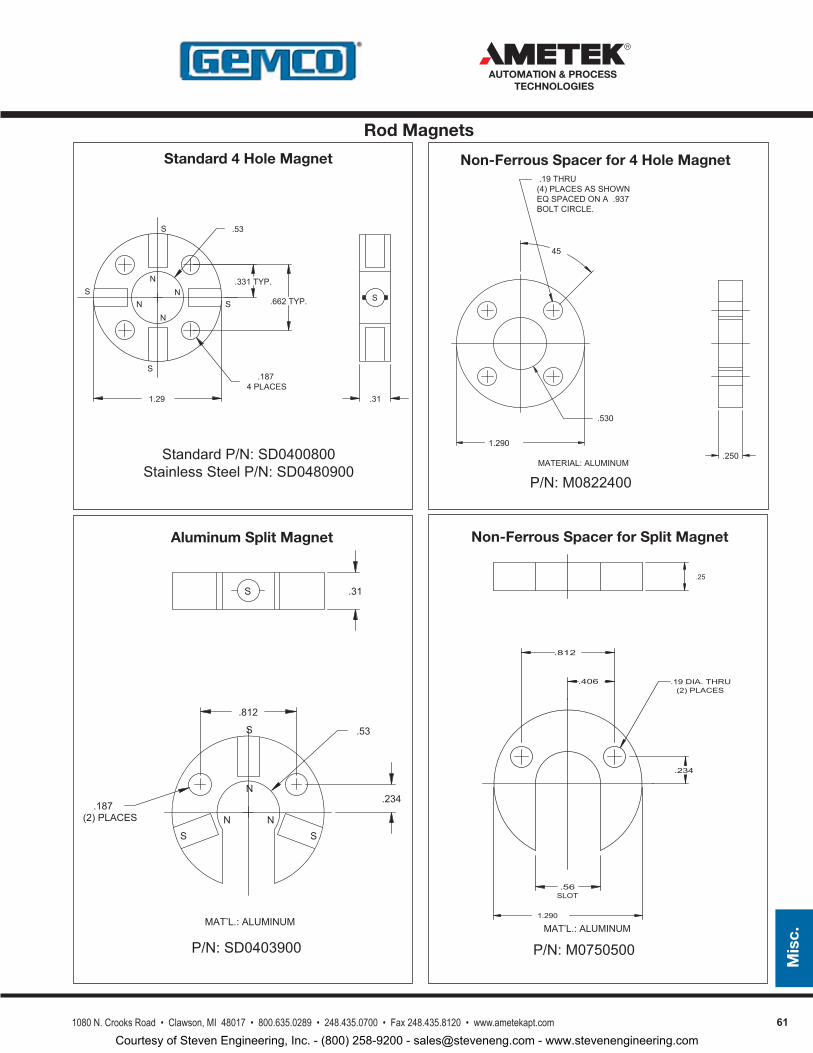
611080 N. Crooks Road • Clawson, MI 48017 • 800.635.0289 • 248.435.0700 • Fax 248.435.8120 • www.ametekapt.com
AUTOMATION & PROCESS TECHNOLOGIES
Mis
c.
45
.19THRU
BOLTCIRCLE.
(4)PLACESASSHOWNEQSPACEDONA .937
MATERIAL:ALUMINUM
.530
1.290.250
P/N:M0822400
Non-Ferrous Spacer for 4 Hole Magnet
SN
NN
N
S
S
S
S
1.29 .31
.53
.331TYP.
.662TYP.
.1874PLACES
StandardP/N:SD0400800StainlessSteelP/N:SD0480900
Standard 4 Hole Magnet
S
N
N
NS
S
S
(2)PLACES
.234
.812
.187
.53
.31
MAT’L.:ALUMINUM
P/N:SD0403900
Aluminum Split Magnet
P/N:M0750500
Non-Ferrous Spacer for Split Magnet
.234
.406
.812
.19DIA.THRU(2)PLACES
.56SLOT
1.290
.25
MAT’L.:ALUMINUM
Rod Magnets
Courtesy of Steven Engineering, Inc. - (800) 258-9200 - [email protected] - www.stevenengineering.com
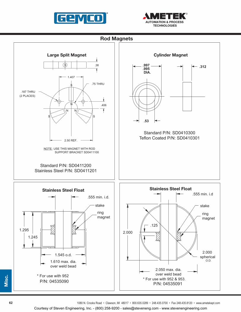
62 1080 N. Crooks Road • Clawson, MI 48017 • 800.635.0289 • 248.435.0700 • Fax 248.435.8120 • www.ametekapt.com
AUTOMATION & PROCESS TECHNOLOGIES
Mis
c.
P/N:04535090
StandardP/N:SD0411200StainlessSteelP/N:SD0411201
Large Split Magnet
2.50REF.
.406
1.407
.75THRU
.38
.187THRU(2PLACES)
S
N
N N
S
SS
NOTE:USETHISMAGNETWITHRODSUPPORTBRACKETSD0411100
.555min.i.d.
1.295
ringmagnet
stake
1.245
1.545o.d.
1.610max.dia.overweldbead
Stainless Steel Float
*Forusewith952
Cylinder Magnet
StandardP/N:SD0410300TeflonCoatedP/N:SD0410301
P/N:04535091
Stainless Steel Float
*Forusewith952&953.
.555min.i.d
2.000
.125
2.000spherical
ringmagnet
stake
2.050max.dia.overweldbead
O.D.
.312
.53
.997
.995DIA.
Rod Magnets
Courtesy of Steven Engineering, Inc. - (800) 258-9200 - [email protected] - www.stevenengineering.com
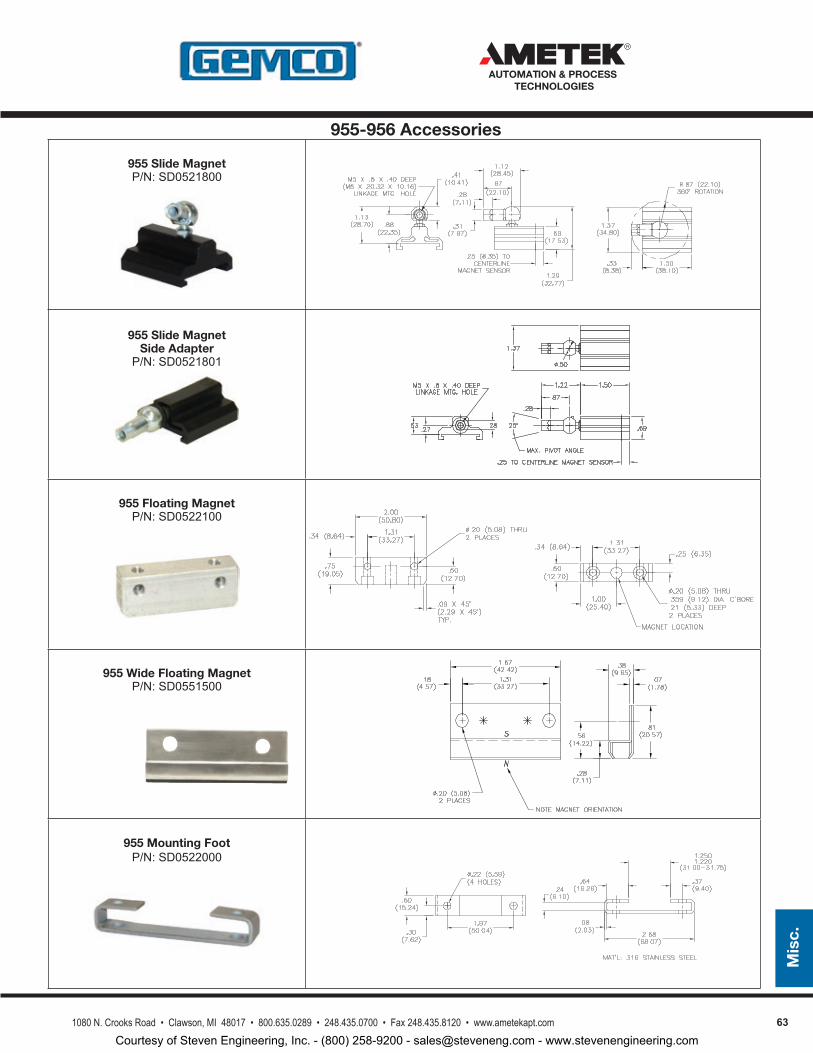
631080 N. Crooks Road • Clawson, MI 48017 • 800.635.0289 • 248.435.0700 • Fax 248.435.8120 • www.ametekapt.com
AUTOMATION & PROCESS TECHNOLOGIES
Mis
c.
955 Slide MagnetP/N:SD0521800
955 Slide Magnet Side Adapter
P/N:SD0521801
955 Floating MagnetP/N:SD0522100
955 Wide Floating MagnetP/N:SD0551500
955 Mounting FootP/N:SD0522000
955-956 Accessories
Courtesy of Steven Engineering, Inc. - (800) 258-9200 - [email protected] - www.stevenengineering.com
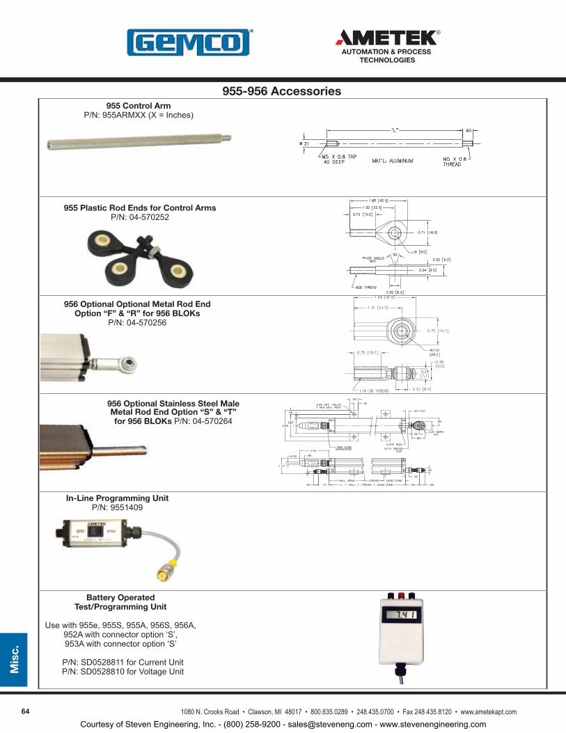
64 1080 N. Crooks Road • Clawson, MI 48017 • 800.635.0289 • 248.435.0700 • Fax 248.435.8120 • www.ametekapt.com
AUTOMATION & PROCESS TECHNOLOGIES
Mis
c.
In-Line Programming UnitP/N:9551409
955 Control ArmP/N:955ARMXX(X=Inches)
955 Plastic Rod Ends for Control ArmsP/N:04-570252
956 Optional Optional Metal Rod End Option “F” & “R” for 956 BLOKs
P/N:04-570256
956 Optional Stainless Steel Male Metal Rod End Option “S” & “T” for 956 BLOKs P/N:04-570264
Battery Operated Test/Programming Unit
Usewith955e,955S,955A,956S,956A,952Awithconnectoroption‘S’,953Awithconnectoroption‘S’
P/N:SD0528811forCurrentUnit P/N:SD0528810forVoltageUnit
955-956 Accessories
Courtesy of Steven Engineering, Inc. - (800) 258-9200 - [email protected] - www.stevenengineering.com
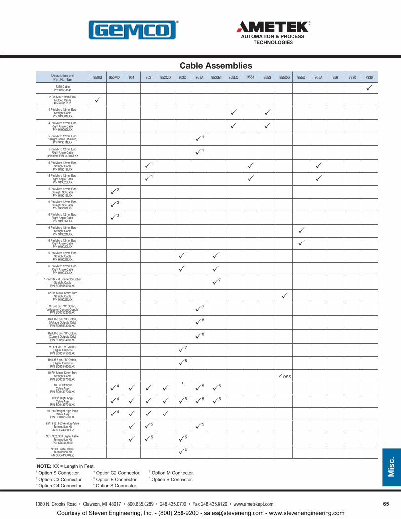
651080 N. Crooks Road • Clawson, MI 48017 • 800.635.0289 • 248.435.0700 • Fax 248.435.8120 • www.ametekapt.com
AUTOMATION & PROCESS TECHNOLOGIES
Mis
c.
Description andPart Number 950IS 950MD 951 952 952QD 953D 953A 953SSI 955LC 955e 955S 955DQ 955D 955A 956 7230 7330
7330 Cable P/N 01533141
2 Pin Mini 16mm Euro Molded CableP/N 04521210
4 Pin Micro 12mm EuroStraight Cable
P/N 949001LXX 4 Pin Micro 12mm Euro
Right Angle Cable P/N 949002LXX
5 Pin Micro 12mm Euro Straight Cable (shielded)
P/N 949011LXX 1
5 Pin Micro 12mm Euro Right Angle Cable
(shielded) P/N 949012LXX 1
5 Pin Micro 12mm Euro Straight Cable
P/N 949019LXX 1 5 Pin Micro 12mm Euro
Right Angle Cable P/N 949020LXX 1
5 Pin Micro 12mm Euro Straight SS Cable P/N 949013LXX 2
6 Pin Micro 12mm Euro Straight SS Cable P/N 949031LXX 3
6 Pin Micro 12mm Euro Right Angle Cable P/N 949032LXX 3
6 Pin Micro 12mm Euro Straight Cable
P/N 949021LXX 6 Pin Micro 12mm Euro
Right Angle Cable P/N 949022LXX
6 Pin Micro 12mm Euro Straight Cable
P/N 949029LXX 1 1
6 Pin Micro 12mm Euro Right Angle Cable P/N 949030LXX 1 1
7 Pin DIN - M Connector Option Straight Cable
P/N SD0558500LXX 7
12 Pin Micro 12mm Euro Straight Cable
P/N 949023LXX MTS-6 pin, “M” Option,
(Voltage or Current Outputs)P/N SD0553200LXX 7
Balluff-8 pin, “B” Option, (Voltage Outputs Only)P/N SD0553300LXX 8
Balluff-8 pin, “B” Option, (Current Outputs Only)P/N SD0553400LXX 8
MTS-6 pin, “M” Option, (Digital Outputs)
P/N SD0554500LXX 7
Balluff-8 pin, “B” Option, (Digital Outputs)
P/N SD0554600LXX 8
10 Pin Micro 12mm Euro Straight Cable
P/N SD0527700LXX OBS
10 Pin Straight Cable Assy
P/N SD0439700LXX 4 5
5 5
10 Pin Right Angle Cable Assy
P/N SD0439701LXX 4 5 5 5
10 Pin Straight High Temp Cable Assy
P/N SD0465500LXX 4 951, 952, 953 Analog Cable
Termination KitP/N SD0443803L25 5 5
951, 952, 953 Digital Cable Termination Kit
P/N SD0443800 5 5
953D Digital Cable Termination Kit
P/N SD0443804L25 6
NOTE:XX=LengthinFeet.1OptionSConnector. 4
OptionC2Connector.7
OptionMConnector.
2OptionC3Connector.5
OptionEConnector.8
OptionBConnector.
3OptionC4Connector.6
OptionSConnector.
Cable Assemblies
Courtesy of Steven Engineering, Inc. - (800) 258-9200 - [email protected] - www.stevenengineering.com
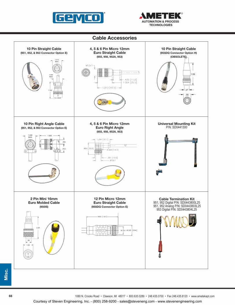
66 1080 N. Crooks Road • Clawson, MI 48017 • 800.635.0289 • 248.435.0700 • Fax 248.435.8120 • www.ametekapt.com
AUTOMATION & PROCESS TECHNOLOGIES
Mis
c.
1.760
1.013MAX.
1.000MAX.
10 Pin Straight Cable(951, 952, & 953 Connector Option E)
4, 5 & 6 Pin Micro 12mm Euro Straight Cable
(955, 956, 952A, 953)
1.69
.58
.37
10 Pin Straight Cable (955DQ Connector Option H)
(OBSOLETE)
4, 5 & 6 Pin Micro 12mm Euro Right Angle(955, 956, 952A, 953)
Universal Mounting KitP/N: SD0441300
2.25
.55
1.00
2 Pin Mini 16mm Euro Molded Cable
(950IS)
12 Pin Micro 12mm Euro Straight Cable
(955DQ Connector Option E)
Cable Termination Kit951, 952 Digital P/N: SD0443800L25
951, 952 Analog P/N: SD0443803L25953 Digital P/N: SD0443804L25
1.965
.450
.812
1.046MAX.
10 Pin Right Angle Cable(951, 952, & 953 Connector Option E)
Cable Accessories
Courtesy of Steven Engineering, Inc. - (800) 258-9200 - [email protected] - www.stevenengineering.com
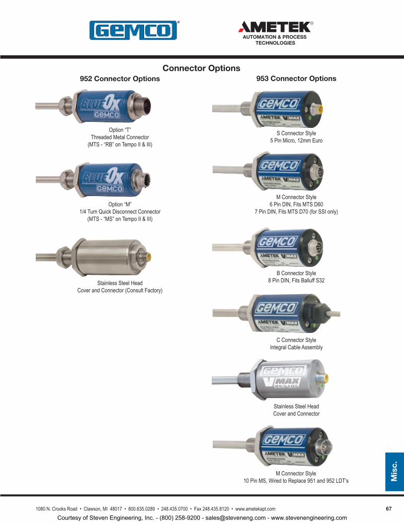
671080 N. Crooks Road • Clawson, MI 48017 • 800.635.0289 • 248.435.0700 • Fax 248.435.8120 • www.ametekapt.com
AUTOMATION & PROCESS TECHNOLOGIES
Mis
c.
S Connector Style5 Pin Micro, 12mm Euro
M Connector Style6 Pin DIN, Fits MTS D60
7 Pin DIN, Fits MTS D70 (for SSI only)
B Connector Style8 Pin DIN, Fits Balluff S32
C Connector StyleIntegral Cable Assembly
Option “T” Threaded Metal Connector
(MTS - “RB” on Tempo II & III)
Option “M” 1/4 Turn Quick Disconnect Connector
(MTS - “MS” on Tempo II & III)
Stainless Steel Head Cover and Connector (Consult Factory)
952 Connector Options 953 Connector Options
Stainless Steel Head Cover and Connector
Connector Options
M Connector Style10 Pin MS, Wired to Replace 951 and 952 LDT’s
Courtesy of Steven Engineering, Inc. - (800) 258-9200 - [email protected] - www.stevenengineering.com
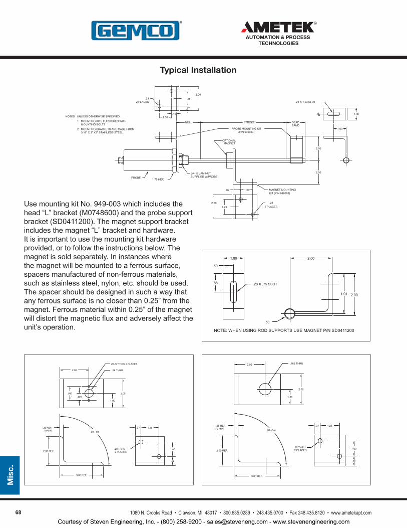
68 1080 N. Crooks Road • Clawson, MI 48017 • 800.635.0289 • 248.435.0700 • Fax 248.435.8120 • www.ametekapt.com
AUTOMATION & PROCESS TECHNOLOGIES
Mis
c.
UsemountingkitNo.949-003whichincludesthehead“L”bracket(M0748600)andtheprobesupportbracket(SD0411200).Themagnetsupportbracketincludesthemagnet“L”bracketandhardware.Itisimportanttousethemountingkithardwareprovided,ortofollowtheinstructionsbelow.Themagnetissoldseparately.Ininstanceswherethemagnetwillbemountedtoaferroussurface,spacersmanufacturedofnon-ferrousmaterials,suchasstainlesssteel,nylon,etc.shouldbeused.Thespacershouldbedesignedinsuchawaythatanyferroussurfaceisnocloserthan0.25”fromthemagnet.Ferrousmaterialwithin0.25”ofthemagnetwilldistortthemagneticfluxandadverselyaffecttheunit’soperation.
1.00 2.00
2.00
.28 X .75 SLOT
.50
.50
.88
1.91
NOTE: WHEN USING ROD SUPPORTS USE MAGNET P/N SD0411200
90 –1/4
2.00
1.00
2.00
.766 THRU
.25 REF.
2.00 REF.
3.00 REF.
.37 1.25
.62
1.00.28 THRU
.19 MIN.
2 PLACES
90 –1/4
2.00
1.00
2.00
.56 THRU
.25 REF.
2.00 REF.
3.00 REF.
.37 1.25
.62
1.00.28 THRU
.19 MIN.
.469.937
#6-32 THRU 2 PLACES
2 PLACES
BAND
OPTIONALMAGNET
NULL STROKE DEAD
1.75 HEX
MAGNET MOUNTINGKIT (P/N 949005)
PROBE MOUNTING KIT(P/N 949003)
2.00
2.003/4-16 JAM NUTSUPPLIED W/PROBE
1.00
1.03
.28 X 1.03 SLOT
1.00.44
1.252.00
.282 PLACES
2.001.25
1.00
2 PLACES.28
.62
PROBE
3/16" X 2" X3" STAINLESS STEEL .2. MOUNTING BRACKETS ARE MADE FROM
MOUNTING BOLTS.1. MOUNTING KITS FURNISHED WITH
NOTES: UNLESS OTHERWISE SPECIFIEDCL
.37
Typical Installation
Courtesy of Steven Engineering, Inc. - (800) 258-9200 - [email protected] - www.stevenengineering.com
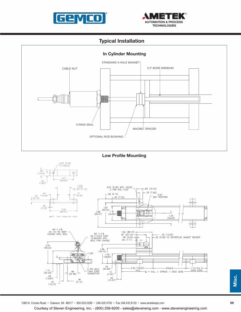
691080 N. Crooks Road • Clawson, MI 48017 • 800.635.0289 • 248.435.0700 • Fax 248.435.8120 • www.ametekapt.com
AUTOMATION & PROCESS TECHNOLOGIES
Mis
c.
Low Profile Mounting
In Cylinder Mounting
STANDARD4-HOLEMAGNET
0.5"BOREMINIMUMCABLENUT
O-RINGSEAL
OPTIONALRODBUSHING
MAGNETSPACER
Typical Installation
Courtesy of Steven Engineering, Inc. - (800) 258-9200 - [email protected] - www.stevenengineering.com
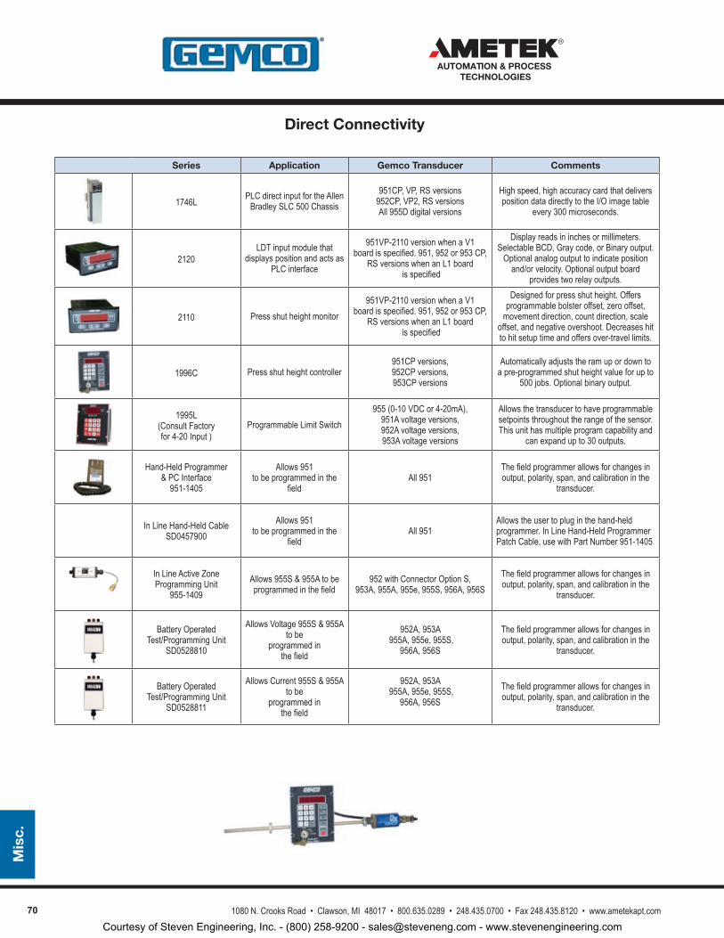
70
Series Application Gemco Transducer Comments
1746L PLC direct input for the Allen Bradley SLC 500 Chassis
951CP, VP, RS versions 952CP, VP2, RS versions All 955D digital versions
High speed, high accuracy card that delivers position data directly to the I/O image table
every 300 microseconds.
2120LDT input module that
displays position and acts as PLC interface
951VP-2110 version when a V1 board is specified. 951, 952 or 953 CP,
RS versions when an L1 board is specified
Display reads in inches or millimeters. Selectable BCD, Gray code, or Binary output.
Optional analog output to indicate position and/or velocity. Optional output board
provides two relay outputs.
2110 Press shut height monitor951VP-2110 version when a V1
board is specified. 951, 952 or 953 CP, RS versions when an L1 board
is specified
Designed for press shut height. Offers programmable bolster offset, zero offset,
movement direction, count direction, scale offset, and negative overshoot. Decreases hit to hit setup time and offers over-travel limits.
1996C Press shut height controller951CP versions,952CP versions,953CP versions
Automatically adjusts the ram up or down to a pre-programmed shut height value for up to
500 jobs. Optional binary output.
1995L(Consult Factory for 4-20 Input )
Programmable Limit Switch955 (0-10 VDC or 4-20mA),
951A voltage versions,952A voltage versions,953A voltage versions
Allows the transducer to have programmable setpoints throughout the range of the sensor. This unit has multiple program capability and
can expand up to 30 outputs.
Hand-Held Programmer & PC Interface
951-1405
Allows 951 to be programmed in the
fieldAll 951
The field programmer allows for changes in output, polarity, span, and calibration in the
transducer.
In Line Hand-Held Cable SD0457900
Allows 951 to be programmed in the
fieldAll 951
Allows the user to plug in the hand-held programmer. In Line Hand-Held Programmer Patch Cable, use with Part Number 951-1405
In Line Active Zone Programming Unit
955-1409Allows 955S & 955A to be programmed in the field
952 with Connector Option S,953A, 955A, 955e, 955S, 956A, 956S
The field programmer allows for changes in output, polarity, span, and calibration in the
transducer.
Battery Operated Test/Programming Unit
SD0528810
Allows Voltage 955S & 955A to be
programmed in the field
952A, 953A 955A, 955e, 955S,
956A, 956S
The field programmer allows for changes in output, polarity, span, and calibration in the
transducer.
Battery Operated Test/Programming Unit
SD0528811
Allows Current 955S & 955A to be
programmed in the field
952A, 953A 955A, 955e, 955S,
956A, 956S The field programmer allows for changes in output, polarity, span, and calibration in the
transducer.
1080 N. Crooks Road • Clawson, MI 48017 • 800.635.0289 • 248.435.0700 • Fax 248.435.8120 • www.ametekapt.com
AUTOMATION & PROCESS TECHNOLOGIES
Mis
c.
Direct Connectivity
Courtesy of Steven Engineering, Inc. - (800) 258-9200 - [email protected] - www.stevenengineering.com
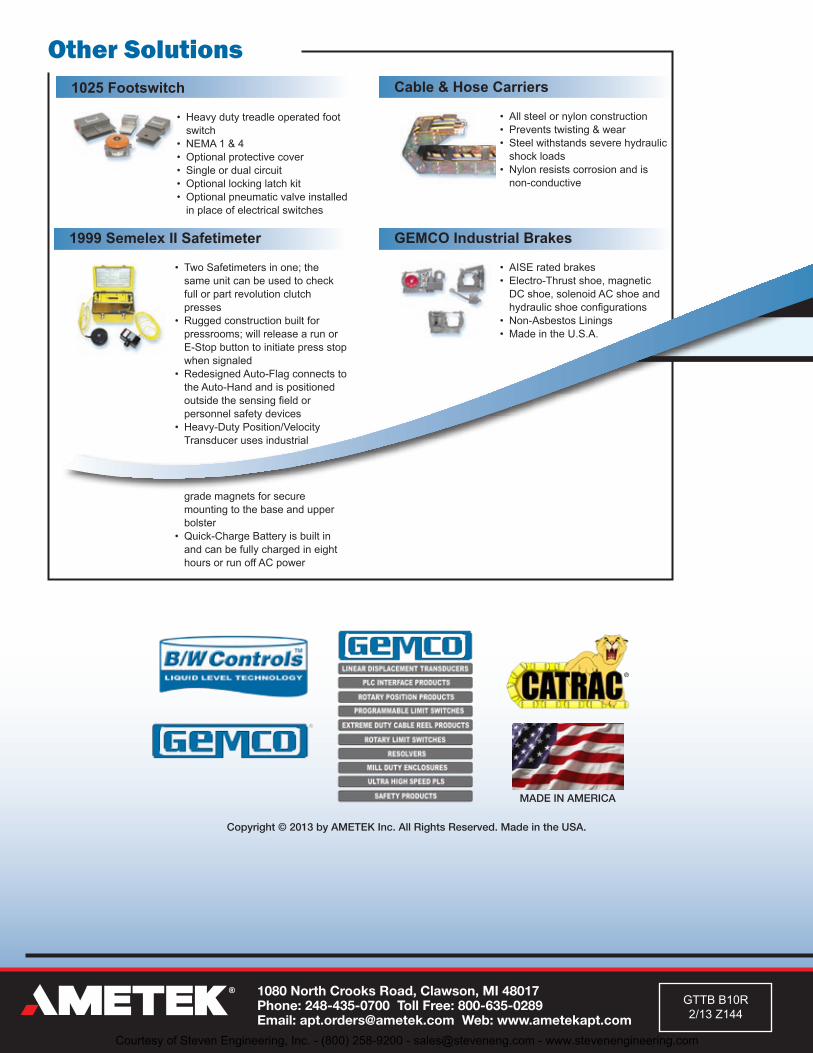
Other Solutions1025 Footswitch
• Heavydutytreadleoperatedfootswitch
• NEMA1&4• Optionalprotectivecover• Singleordualcircuit• Optionallockinglatchkit• Optionalpneumaticvalveinstalledinplaceofelectricalswitches
GEMCO Industrial Brakes
• AISEratedbrakes• Electro-Thrustshoe,magneticDCshoe,solenoidACshoeandhydraulicshoeconfigurations
• Non-AsbestosLinings• MadeintheU.S.A.
Cable & Hose Carriers
• Allsteelornylonconstruction• Preventstwisting&wear• Steelwithstandsseverehydraulicshockloads
• Nylonresistscorrosionandisnon-conductive
1999 Semelex II Safetimeter
• TwoSafetimetersinone;thesameunitcanbeusedtocheckfullorpartrevolutionclutchpresses
• Ruggedconstructionbuiltforpressrooms;willreleasearunorE-Stopbuttontoinitiatepressstopwhensignaled
• RedesignedAuto-FlagconnectstotheAuto-Handandispositionedoutsidethesensingfieldorpersonnelsafetydevices
• Heavy-DutyPosition/VelocityTransducerusesindustrialgrademagnetsforsecuremountingtothebaseandupperbolster
• Quick-ChargeBatteryisbuiltinandcanbefullychargedineighthoursorrunoffACpower
MADE IN AMERICA
Copyright © 2013 by AMETEK Inc. All Rights Reserved. Made in the USA.
®
1080 North Crooks Road, Clawson, MI 48017 Phone: 248-435-0700 Toll Free: 800-635-0289 Email: [email protected] Web: www.ametekapt.com
GTTBB10R2/13Z144
Courtesy of Steven Engineering, Inc. - (800) 258-9200 - [email protected] - www.stevenengineering.com