Embed Size (px)
Citation preview

Service ManualOrder No. PHAT070801S3
Automatic Rice CookerSR-G06G/G10SG/G18SG
(Hong Kong)
© 2007 Panasonic Home Appliance (Thailand) Co.,Ltd All rights reserved. Unauthorized copying and distrbution is a violation of law.
Specification
Specification subject to change without notice.
Model SR-G06G SR-G10SG SR-G18SGDetail
Power Source 1 Phase AC 120V 60 Hz
Powerconsumption
Cooking 300W 450W 650W
Warming - 43.7W 45W
Cooking capacity 0.18 ~ 0.6 L 0.18 ~ 1.0 L 0.54 ~ 1.8 L
Center thermostatworking temperature 134 °C ± 6 °C
Keep warm temperature More than or equal to 80 °C (After 1 Hr. keep warm)
Thermal fuse specification 110 °C 250V 10A
Dimension (mm)Width x Depth x Height 254 x 201 x 209 282 x 229 x 238 325 x 283 x 255
Weight 1.5 kg 2.1 kg 2.7 kg
Power Cord (approx.) 1.0 m
Accessories Rice Scoop Measuring Cup, Steaming Basket
2
SR-G06G/SR-G10SG/SR-G18SG
WARNINGThis service information is designed for experienced repair technicians only and is not designed for use by the general public.It does not contain warnings or cautions to advise non-technical individuals of potential dangers in attempting to service a product.Products powered by electricity should be serviced or repaired only by experienced professional technicians. Any attempt to service or repair the product or products dealt with in this service information by anyone else could result in serious injury or death.
There are special components used in this equipment which are important for safety. These parts are marked by in the SchematicDiagrams, Circuit Board Diagrams, Exploded Views and Replacement Parts List. It is essential that these critical parts should be replaced with manufacturer’s specified parts to prevent shock, fire or other hazards. Do not modify the original design without permission of manufacturer.
IMPORTANT SAFETY NOTICE
CONTENTS
1. SCHEMATIC DIAGRAM & WIRING DIAGRAM ............................................................................3-4
2. FUNCTION OF CENTER THERMOSTAT AND THERMAL FUSE ................................................5-6
3. TROUBLE SHOOTING GUIDE .....................................................................................................7-8
4. TEST PROCEDURE ....................................................................................................................9-10
5. EXPLODED VIEW ..........................................................................................................................11
6. REPLACEMENT OF PARTS LIST & PACKING LIST ..............................................................12-14
Page

3
SR-G06G/SR-G10SG/SR-G18SG
SCHEMATIC DIAGRAM (SR-G06G)
WIRING DIAGRAM (SR-G06G)
LAMP RESIST. LAMP RESIST.T. F.
INPUT
RED
REDCN1
BLUECN2
CAST HEATER
COOKING NEON LAMP
LAMP BORD
KEEP WARM NEON LAMP
MICA HEATER ASS’Y
NC
NCC
WHITECN3
CN4YELLOW
RED
SWITCH
GREEN
Red tube (N)InsulationColor : Blue
In case of wire broken, make sure thatearth wire is the last wire to be disconnected
Red tube (L)InsulationColor : Brown
Green tube (E)InsulationColor : Green
Lamp lead wire A (Red)
Lamp lead wire D (Yellow)
Power Cord Wire (Red)
Lamp lead wire D (Yellow)
Lamp lead wire C (White)
Lamp lead wire C (White) Lead wire of mica heater (White)
Lamp lead wire B (Blue) shall not pass on top side of other ring terminal
1. SCHEMATIC DIAGRAM & WIRING DIAGRAM

4
SR-G06G/SR-G10SG/SR-G18SG
LAMP RESIST.T. F.
INPUT
RED
RED
CN2BLUE
CAST HEATER
COOKING NEON LAMP
LAMP BORD
NCC
CN1YELLOW
CN3RED
SWITCH
GREEN
Red tube (N)InsulationColor : Blue
In case of wire broken, make sure thatearth wire is the last wire to be disconnected
Red tube (L)InsulationColor : Brown
Lamp lead wire C (Red)
Lamp lead wire A (Yellow)
Power Cord Wire (Red)
Lamp lead wire B (Blue)
Lamp lead wire B (White)
SCHEMATIC DIAGRAM (SR-G10SG/SR-G18SG)
WIRING DIAGRAM (SR-G10SG/SR-G18SG)
1. SCHEMATIC DIAGRAM & WIRING DIAGRAM

5
SR-G06G/SR-G10SG/SR-G18SG
2. FUNCTION OF CENTER THERMOSTAT AND THERMALFUSEA. Center Thermostat
The center thermostat senses when the bottom of the rice cooker pan reach 134°C ± 6°C. And it’s action turns off the cooking cycle, and starts the warming cycle.
Refer to these figures showing the center thermostat construction and cooking position. As the metal is heated, its ability to be attracted by the magnet decreases.
Finally, the inner spring pressure becomes stronger than the magnetic pull and the metal and magnet will pop apart. The rod activates the switch lever which causes the auxiliary lever to press the micro-switch button into the warming cycle.
B. Switch-On Preventive System
This is design to prevent the rice cooker from being turned on without the pan placed into position.1) Normally when the pan is inserted properly into the rice cooker, the pan will depress the
center thermostat. The center thermostat outer spring will be compressed. In this case when the switch button is depressed, the following will happen:a. The auxiliary lever will release the micro-switch button. This puts the micro-switch in the
cook position.b. The switch lever will push the rod which will allow the magnet to meet with the metal.c. When the rice is cooked and the proper temperature has been reached 134°C ± 6°C, the
metal and magnet will pop apart as described in the center thermostat operation above.d. The rod will push the switch lever and cause the auxiliary lever to depress the micro-
switch button. This puts the micro-switch in the warming position.
2) When the pan is not in place within the rice cooker, the center thermostat is not depressed.a. In this condition, the outer spring is not compressed within the center thermostat
preventing the metal from reaching its normal operating position.b. When the switch button is depressed, the switch lever and auxiliary lever work as above
but the magnet cannot come in contact with the metal to hold the switch lever in the cook position. This happens because the switch lever hits the thermostat case and cannot push the rod, with the magnet attached, all they way up to meet with the metal.
c. When the pressure is taken off the switch button, the switch lever releases immediately to the open or warm positions.
Metal
Magnet
Inner spring Cooking heater
Rod
10mm
Outer spring
Switch lever
Cook switch button
Micro switch
Thermostat case
Thermostat surface
Auxiliary lever
Metal
Magnet Inner spring Cooking heater
Rod Inner spring
Outer spring Switch lever
Cook switch button
Micro switch NC C
Center thermostat construction
(Cooking Position) (Warming or Off Position)Figure 1
6
SR-G06G/SR-G10SG/SR-G18SG
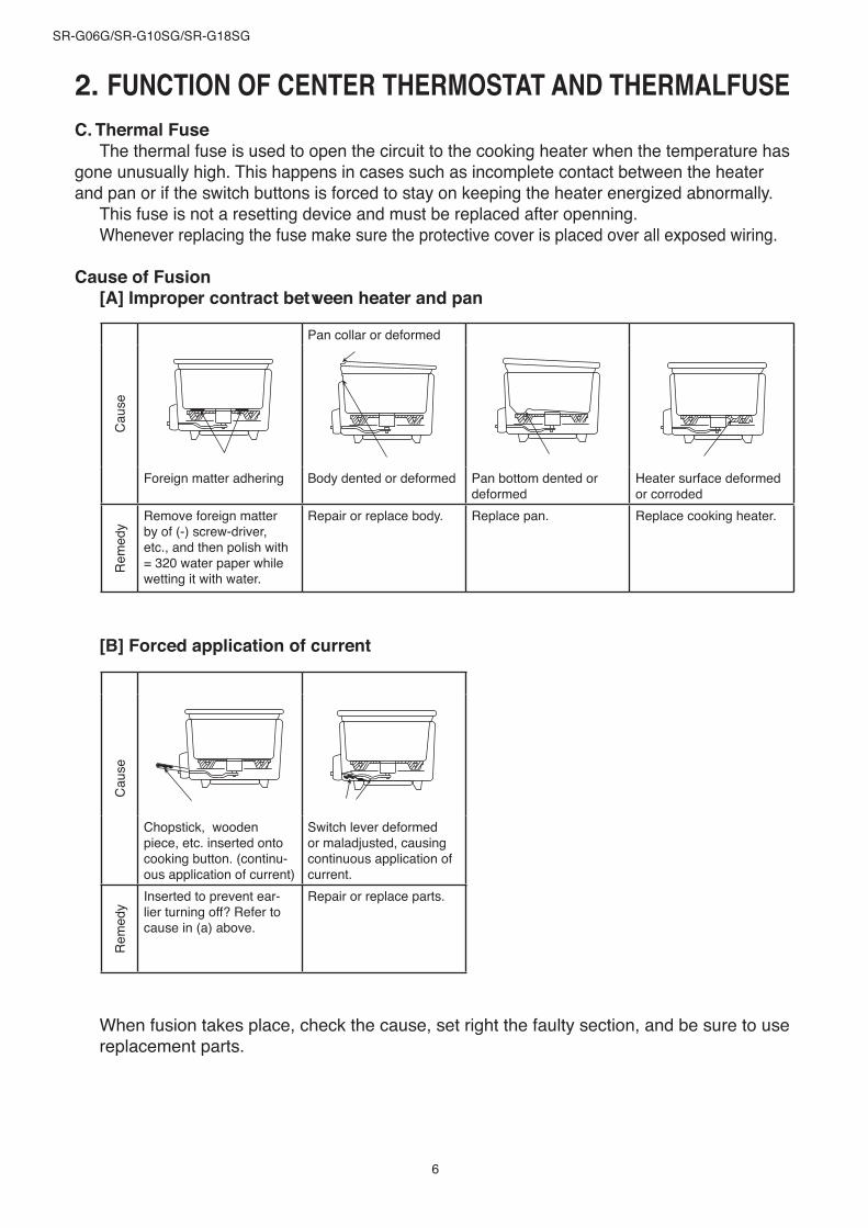
C. Thermal FuseThe thermal fuse is used to open the circuit to the cooking heater when the temperature has
gone unusually high. This happens in cases such as incomplete contact between the heater and pan or if the switch buttons is forced to stay on keeping the heater energized abnormally.
This fuse is not a resetting device and must be replaced after openning.Whenever replacing the fuse make sure the protective cover is placed over all exposed wiring.
Cause of Fusion[A] Improper contract between heater and pan
[B] Forced application of current
Cau
se
Pan collar or deformed
Foreign matter adhering Body dented or deformed Pan bottom dented or deformed
Heater surface deformed or corroded
Rem
edy
Remove foreign matter by of (-) screw-driver, etc., and then polish with = 320 water paper while wetting it with water.
Repair or replace body. Replace pan. Replace cooking heater.
Cau
se
Chopstick, wooden piece, etc. inserted onto cooking button. (continu-ous application of current)
Switch lever deformed or maladjusted, causing continuous application of current.
Rem
edy
Inserted to prevent ear-lier turning off? Refer to cause in (a) above.
Repair or replace parts.
When fusion takes place, check the cause, set right the faulty section, and be sure to use replacement parts.
2. FUNCTION OF CENTER THERMOSTAT AND THERMALFUSE

7
SR-G06G/SR-G10SG/SR-G18SG
Symptom Diagnosis Remedy
Cooking function● Cooking fails (Cooking
lamp is not shown)No continuity of cord?
Yes ● Replace AC cord.
No continuity of thermal fuse?
Yes ● Locate cause for fusing and
replace fuse.
No continuity of micro switch?Yes
● Replace Frame ass’y.
Center thermostat is broken?(Checked evaporation test)
Yes
● Replace center thermostat.
Switch lever properly adjust?No
● Adjust Switch lever.
● Cooking fails (Cooking lamp is not shown)
No continuity of sheathed heater?
Yes
● Replace sheathed heater.
● Thermal fuse blownForced application of current?
Yes ● Explain correct usage.
● Rice burns (Brown color)Center thermostat defective?(Check with evaporation test)
Yes
● Replace center thermostat.
Switch lever has been properly adjusted?
No
● Adjust Lever.
Usage correct?● Rice is not rinced well enough?● Using with low rated voltage?● Too much water input for cooking?
Yes
● Explain correct usage.
When receiving the cooker to be repaired, be sure to always take charge of not only the cooker body but also the pan and the lid, and ask for details as to the symptom of the trouble.Furthermore, when making troubleshooting of each part, be sure to remove the power plug from the socket.
No
No
No
No
No
Yes
3. TROUBLESHOOTING GUIDE

8
SR-G06G/SR-G10SG/SR-G18SG
Symptom Diagnosis Remedy● Earlier Switching-off● Poor cooking finish
Too hardToo softHalf-boiled
Poor contact between pan and sheathed heater? (Check with bubbling test)
Yes ● Replace pan or sheathed
heater.
Center thermostat defective?(Check with evaporation test)
Yes
● Replace Center thermostat.
Switch lever has been properly adjusted?No
● Adjust switch lever.
Usage correct?● Too small or large in rice quantity.● Too small or large in water quantity.● Switched off once by hand in cooking
process.● Switched off by shocks given in cooking
process.● Rice not untied.
● Explain correct usage.
Keep warm function● Warming fails (Warm lamp
not shown)Micro switch change contact to NO (Warm
mode) after cooking is done?
No
● Adjust switch lever.
● Warming fails (Warm lamp shown)
No continuity of warming heater?
Yes
● Replace warming heater.
No
No
Yes
3. TROUBLESHOOTING GUIDE

9
SR-G06G/SR-G10SG/SR-G18SG
1. Bubbling testInput the pan in the main body, and lightly rotate the pan clockwise and counter clockwise
to set the pan on the heating plate properly.1. Fill water until the center area of the pan bottom is dipped, and close the lid. Then turn
on the boiling switch.2. When it beings boiling to produce steam, remove the lid and immediately check the
bubbling condition on the pan bottom.3. Bubbling condition is shown in figure 3.
A. Bubbles generate through out the circumference of the pan bottom ............... ProperB. Bubbles does not generate on more than one quater part of the pan bottom
circuference .................................................................................................. Improper
If it is improper, it may result from the insfficient contact between the pan bottom and the sheathed heater. Check the pan bottom and the sheathed heater for foreign material remained. Clean up the foreign materials or replace the parts.
2. Evaporation test1. After satisfactory bubbling is confirmed, remove the lid and put a weight on the cooker.2. Cover the entire pan bottom with 2 or 3 pieces of tissue paper (or gauze), and turn on
the switch subsequently.3. The cooker is considered acceptable if the timing when steam generation comes to
a stop after water of the pan bottom has evaporated, is within 1 minute before and after the cooking switch is turned off. If these requirements are not satisfied, check the center thermostat as well as the contacted condition between the pan bottom and the cooking heater, and then repair or replace the parts.
5 cm.
.mc 04
Pan (viewed from above)
Pan flange section
Holes of tissue paper
Tissue paper
Water Level
Sheathed heaterCenter thermostat
Figure 2 Figure 3
Water Level
A B
4. TESTING PROCEDURE

10
SR-G06G/SR-G10SG/SR-G18SG
3. Boiling control lever adjustmentSuch a mechanical operation as center thermostat goes up and down is used to turn on
and off the micro-switch. Check and adjust this relationship as shown below.
When the boiling switch is turned on. When the boiling switch is turned off.
Checking The auxiliary lever presses the push-button (The “WARM” lamp comes on.)
The auxiliary lever does not press the push-button (The “COOK” lamp comes on.)
Adjusting To gain the above relationship, adjust the auxiliary lever by bending it with long nose pliers.
4. TESTING PROCEDURE

11
SR-G06G/SR-G10SG/SR-G18SG
A-2
2-2
32
1-2
23
24
4-1
5
6
7
9
2122
8
19
18
13
1510
14
12
11
16
17
20C
B
E
H
I
D
G
F
5. EXPLODED VIEW

12
SR-G06G/SR-G10SG/SR-G18SG
PARTS LISTNo. Part Name Part Number SR-G06G SR-G10SG SR-G18SG Remark 1-2 AQB01T280-WU GLASS LID ASS’Y 1 - - White 1-2 AQB01T280-EG GLASS LID ASS’Y 1 - - Silver 1-2 AQB01T279-WU GLASS LID ASS’Y - 1 - White 1-2 AQB01T279-EG GLASS LID ASS’Y - 1 - Silver 1-2 AQB01T278-WU GLASS LID ASS’Y - - 1 White 1-2 AQB01T278-EG GLASS LID ASS’Y - - 1 Silver 2-1 AQB10T280-WU LID KNOB 1 - - White 2-1 AQB10T280-EG LID KNOB 1 - - Silver 2-2 AQB10T278-WU LID KNOB - 1 1 White 2-2 AQB10T278-EG LID KNOB - 1 1 Silver 3-2 AQB01T280 GLASS LID 1 - - 3-2 AQB01T279 GLASS LID - 1 - 3-2 AQB01T278 GLASS LID - - 1 4-1 AQE50T272 ALUMINIUM PAN 1 - - 4-1 AQE50T271 ALUMINIUM PAN - 1 - 4-1 AQH50H276 ALUMINIUM PAN - - 1 5 ASR00H920-0U THERMOSTAT ASS’Y 1 1 1 6 AQS61T27210U OUTER SPRING 1 - - 6 AQS61T27010U OUTER SPRING - 1 1 7 AQL20T272-0U CAST HEATER ASS’Y 1 - - 7 AQL20T270-0U CAST HEATER ASS’Y 1 1 8 AQE30T271-WU HANDLE 2 2 - White 8 AQE30T271-EG HANDLE 2 2 - Silver 8 AQE30T270-WU HANDLE - - 2 White 8 AQE30T270-EG HANDLE - - 2 Silver 9 AQE13T272-WU BODY COMPLETE 1 - - White 9 AQE13T272-U2 BODY COMPLETE 1 - - Silver 9 AQE13T271-WU BODY COMPLETE - 1 - White 9 AQE13T271-U2 BODY COMPLETE - 1 - Silver 9 AQE13T270-WU BODY COMPLETE - - 1 White 9 AQE13T270-U2 BODY COMPLETE - - 1 Silver
10 AQN00T272-WU SWITCH ASS’Y 1 - - White 10 AQN00T272-EG SWITCH ASS’Y 1 - - Silver 10 AQN00T271-WU SWITCH ASS’Y - 1 - White 10 AQN00T271-EG SWITCH ASS’Y - 1 - Silver 10 AQN00T270-WU SWITCH ASS’Y - - 1 White 10 AQN00T270-EG SWITCH ASS’Y - - 1 Silver 11 AQN10T272-WU SWITCH PANEL 1 - - White 11 AQN10T272-EG SWITCH PANEL 1 - - Silver 11 AQN10T270-WU SWITCH PANEL - 1 - White 11 AQN10T270-EG SWITCH PANEL - 1 - Silver 11 AQN10T270-WU SWITCH PANEL - - 1 White 11 AQN10T270-EG SWITCH PANEL - - 1 Silver 12 AQN85T27210U LAMP BOARD ASS'Y 1 - - 12 AQN85T27110U LAMP BOARD ASS'Y - 1 - 12 AQN85T27010U LAMP BOARD ASS'Y - - 1
6. REPLACEMENT OF PARTS LIST & PACKING LIST

13
SR-G06G/SR-G10SG/SR-G18SG
PARTS LISTNo. Part Name Part Number SR-G06G SR-G10SG SR-G18SG Remark 13 AQN65T270 WIRING TIED 1 - - 13 AQL65T270 WIRING TIED - 1 1 14 AQN20T272-WT DECORATIVE PANEL 1 - - White 14 AQN20T272-UH DECORATIVE PANEL 1 - - Silver 14 AQN20T270-WT DECORATIVE PANEL - 1 1 White 14 AQN20T270-UH DECORATIVE PANEL - 1 1 Silver 15 AQN60T272-0U FRAME COMPLETE 1 - - 15 AQN60T271-0U FRAME COMPLETE - 1 - 15 AQN60T270-0U FRAME COMPLETE - - 1 16 AQN31T272-WU SWITCH BUTTON 1 - - White 16 AQN31T272-EG SWITCH BUTTON 1 - - Silver 16 AQN31T270-WU SWITCH BUTTON - 1 1 White 16 AQN31T270-EG SWITCH BUTTON - 1 1 Silver 17 AQL70T270-0U MICA HEATER ASS’Y - 1 1 18 AQL92T270 WIRING TERMINAL ASS’Y - 1 1 19 AQH20T270-WU BOTTOM PLATE ASS’Y 1 - - White 19 AQH20T270-EG BOTTOM PLATE ASS’Y 1 - - Silver 19 AQH20T271-WU BOTTOM PLATE ASS’Y - 1 - White 19 AQH20T271-EG BOTTOM PLATE ASS’Y - 1 - Silver 19 AQH20T270-WU BOTTOM PLATE ASS’Y - - 1 White 19 AQH20T270-EG BOTTOM PLATE ASS’Y - - 1 Silver 20 AQY50H280-WU NAME PLATE 1 - - White 20 AQY50H280-EG NAME PLATE 1 - - Silver 20 AQY50H279-WU NAME PLATE - 1 - White 20 AQY50H279-UG NAME PLATE - 1 - Silver 20 AQY50H278-WU NAME PLATE - - 1 White 20 AQY50H278-UG NAME PLATE - - 1 Silver 21 AQQ00H272-0U POWER CORD ASS’Y 1 - - 21 AQQ00H277-0U POWER CORD ASS’Y - 1 - 21 AQQ00H276-0U POWER CORD ASS’Y - - 1 22 ASR577Y120-K CORD BUSHING 1 1 1 23 ASR792-454BK MEASURING CUP 1 1 1 24 AQK25T277-W9 STEAM BASKET 1 24 AQK25T276-W9 STEAM BASKET 1
6. REPLACEMENT OF PARTS LIST & PACKING LIST

14
SR-G06G/SR-G10SG/SR-G18SG
LIST OF SCREW No. Part Name Part Number SR-G06G SR-G10SG SR-G18SG Remark A-2 QB06T270 ALUMINIUM SCREW 1 1 1 B XYN4+C10FNS SEMS SCREW 2 2 2 C XTN4+10BFJ TAPPING SCREW 2 2 2 D XTN4+8BFJ TAPPING SCREW 1 1 1 E XTN4+6FFJ TAPPING SCREW 2 2 2 F XTN4+14BFJ TAPPING SCREW - 1 1 G XYN4+C7FNS TAPPING SCREW 1 1 1 H XTN4+8BFJ TAPPING SCREW 1 1 1
I XYC4+CF6FJ SEMS TAPPING SCREW 1 1 1
PACKING LISTNo. Part Name Part Number SR-G06G SR-G10SG SR-G18SG Remark
1 AQY00H2761 OPERATING INSTRUCTION 1 1 -
1 AQY00H2701 OPERATING INSTRUCTION - - 1
2 AQZ11T270 UPPER PAD - - 2 2 AQZ11T271 UPPER PAD - 2 - 2 AQZ11T272 UPPER PAD 2 - - 3 ASR758T140A RUST PROOF PAPER 1 1 1 4 AQZ12T272 LOWER PED A 1 - - 4 AQZ12T271 LOWER PED A - 1 - 4 AQZ12T270 LOWER PED A - - 1 5 AQZ13T772 LOWER PED B 1 - - 5 AQZ13T271 LOWER PED B - 1 - 5 AQZ13T270 LOWER PED B - - 1 6 AQZ12T272-WU INNER PACKING CASE 1 - - 6 AQZ01H270-W9 INNER PACKING CASE - 1 - 6 AQZ01H278-WU INNER PACKING CASE - - 1 7 AQZ80H280-UG POS LABEL 1 - - 7 AQZ80H279-UG POS LABEL - 1 - 7 AQZ80H278-UG POS LABEL - - 1 8 AQZ31H276-UG PACKING CASE LABEL 1 1 1
6. REPLACEMENT OF PARTS LIST & PACKING LIST