Embed Size (px)
Citation preview
ORDER GUIDE RTK7
Configure your required system in 12 or 24 V.
Version 1/ 2012 – Page 3
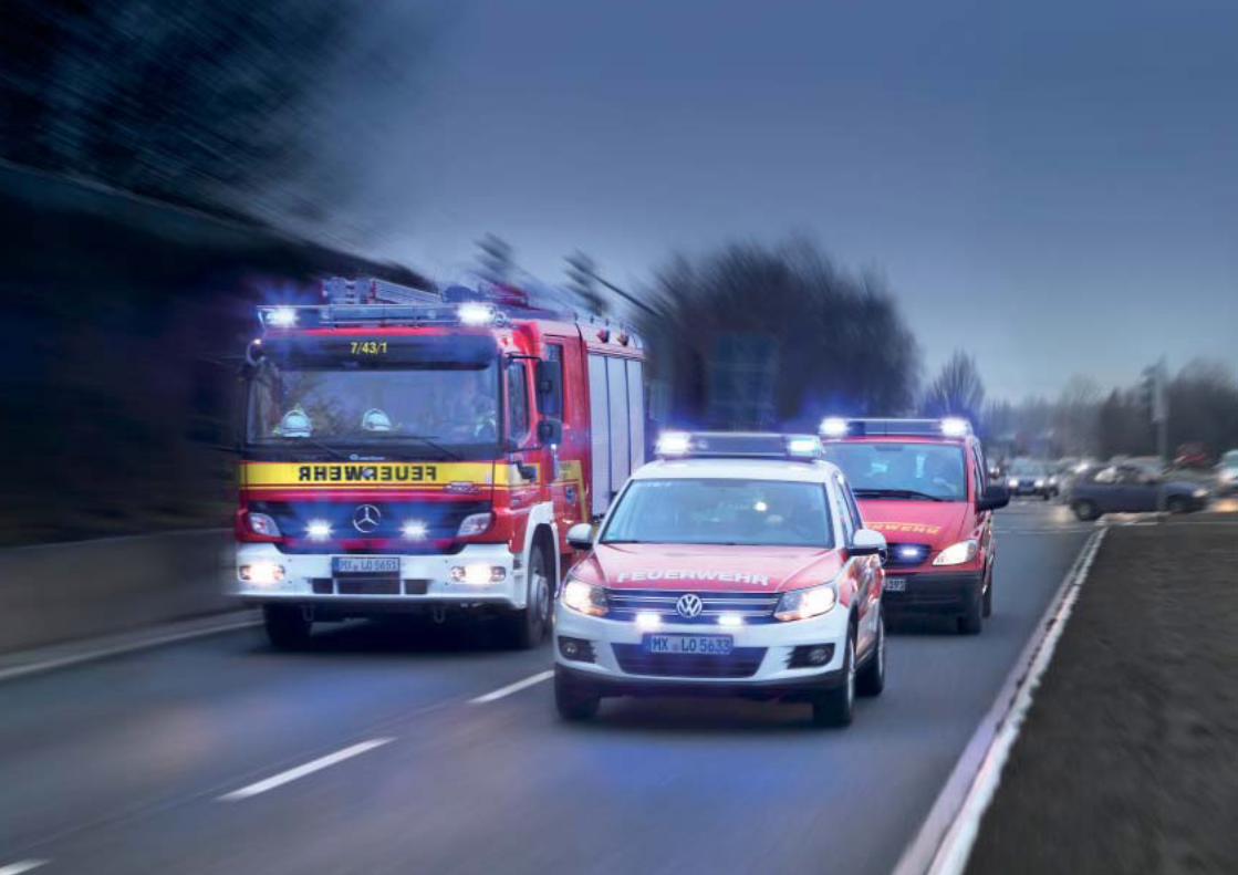
HELLA RTK7 Configuration and orders
The RTK7 module system offers thousands of configuration possibilities.
You can use this document to put your required system together item by item in
12 or 24 V version.
Page 4–10 Overview of the individual modules and components.
Here you choose which elements you would like in your RTK7. Certain modules are positioned in the main beacons, others have been designed for placement in the central section of the housing. On page 4 you will find the the inner dimensions available for module placement at the front and rear in the remaining widths calculator columns. Enter the values relevant for your system width in the columns and subtract the module dimensions of the elements you require accordingly at the front or back. Now transfer the new remaining widths to the next page.
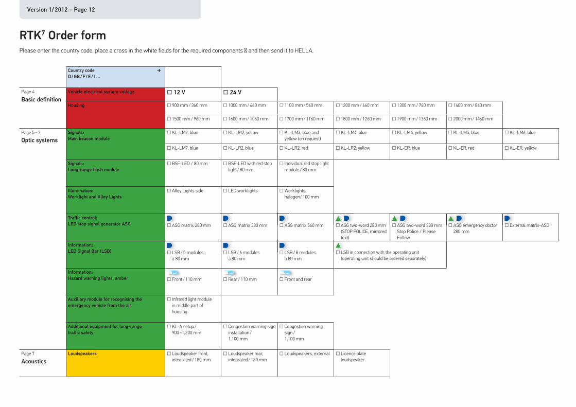
Page 12–13 The order form.
Mark the modules and components you want with a cross and send the form to HELLA. You can see an example below.
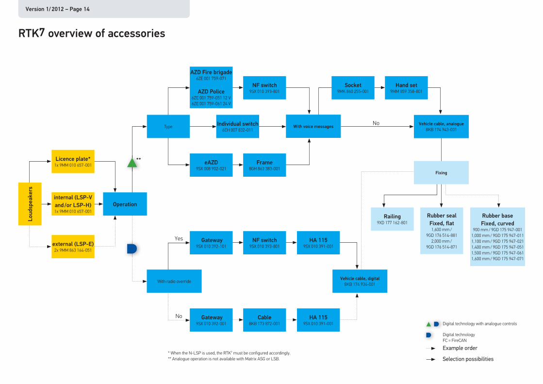
Page 14 Overview of accessories.
The schematic overview shows you which RTK7 accessories can be combined and which parts are required for the function.
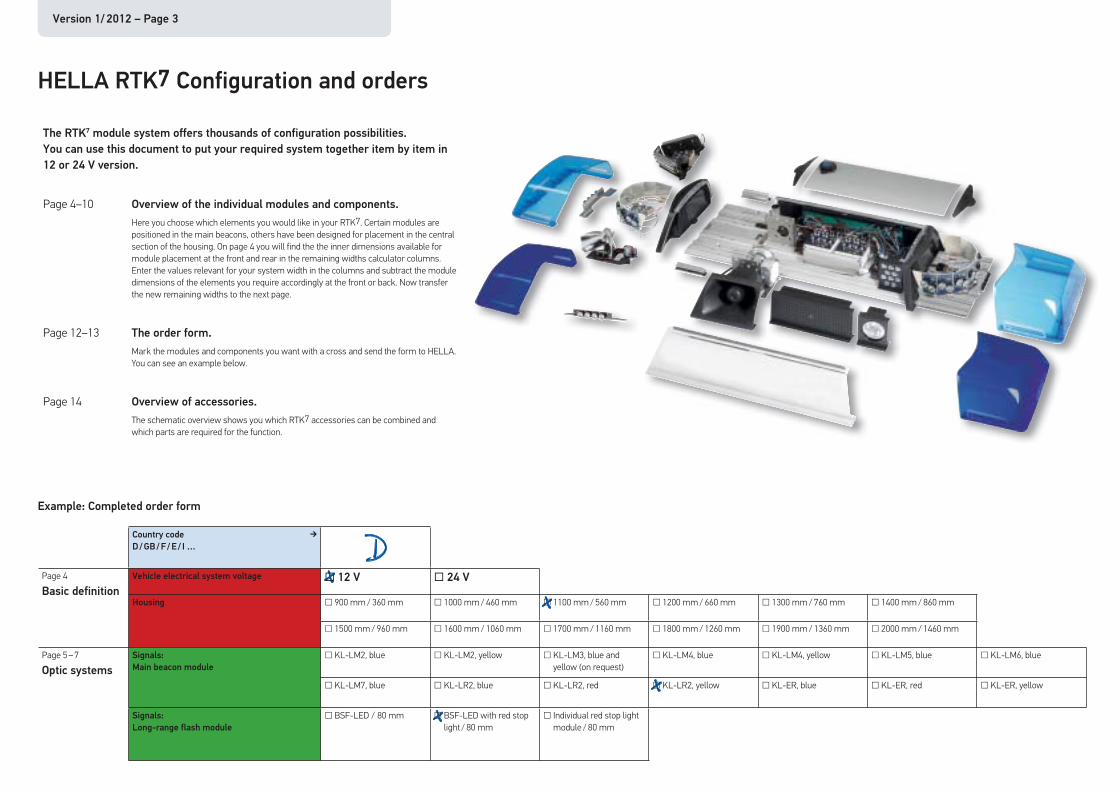
Example: Completed order form
Country code
D / GB / F / E / I …
Page 4
Basic definition
Vehicle electrical system voltage □ 12 V □ 24 V
Housing □ 900 mm / 360 mm □ 1000 mm / 460 mm □ 1100 mm / 560 mm □ 1200 mm / 660 mm □ 1300 mm / 760 mm □ 1400 mm / 860 mm
□ 1500 mm / 960 mm □ 1600 mm / 1060 mm □ 1700 mm / 1160 mm □ 1800 mm / 1260 mm □ 1900 mm / 1360 mm □ 2000 mm / 1460 mm
Page 5 – 7
Optic systems
Signals:
Main beacon module
□ KL-LM2, blue □ KL-LM2, yellow □ KL-LM3, blue and yellow (on request)
□ KL-LM4, blue □ KL-LM4, yellow □ KL-LM5, blue □ KL-LM6, blue
□ KL-LM7, blue □ KL-LR2, blue □ KL-LR2, red □ KL-LR2, yellow □ KL-ER, blue □ KL-ER, red □ KL-ER, yellow
Signals:
Long-range flash module
□ BSF-LED / 80 mm □ BSF-LED with red stop light / 80 mm
□ Individual red stop light module / 80 mm
�
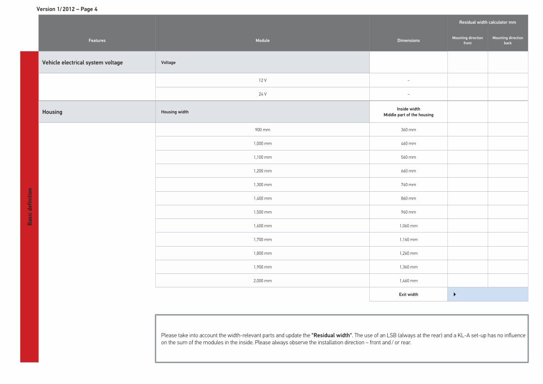
Version 1/ 2012 – Page 4
Residual width calculator mm
Features Module DimensionsMounting direction
front
Mounting direction
back
Basic
de
fin
itio
n
Vehicle electrical system voltage Voltage
12 V –
24 V –
Housing Housing widthInside width
Middle part of the housing
900 mm 360 mm
1,000 mm 460 mm
1,100 mm 560 mm
1,200 mm 660 mm
1,300 mm 760 mm
1,400 mm 860 mm
1,500 mm 960 mm
1,600 mm 1,060 mm
1,700 mm 1,160 mm
1,800 mm 1,260 mm
1,900 mm 1,360 mm
2,000 mm 1,460 mm
Exit width �
Please take into account the width-relevant parts and update the "Residual width". The use of an LSB (always at the rear) and a KL-A set-up has no influence on the sum of the modules in the inside. Please always observe the installation direction – front and / or rear.
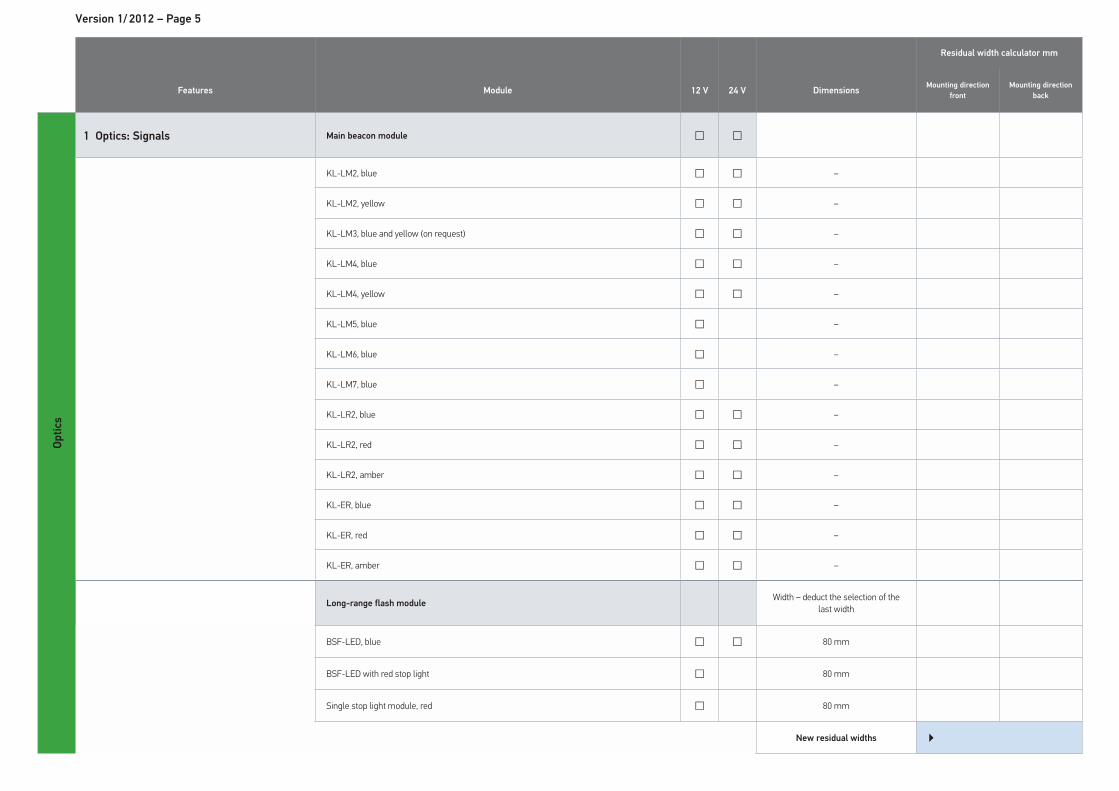
Version 1/ 2012 – Page 5
Residual width calculator mm
Features Module 12 V 24 V DimensionsMounting direction
front
Mounting direction
back
Op
tics
1 Optics: Signals Main beacon module � �
KL-LM2, blue � � –
KL-LM2, yellow � � –
KL-LM3, blue and yellow (on request) � � –
KL-LM4, blue � � –
KL-LM4, yellow � � –
KL-LM5, blue � –
KL-LM6, blue � –
KL-LM7, blue � –
KL-LR2, blue � � –
KL-LR2, red � � –
KL-LR2, amber � � –
KL-ER, blue � � –
KL-ER, red � � –
KL-ER, amber � � –
Long-range flash moduleWidth – deduct the selection of the
last width
BSF-LED, blue � � 80 mm
BSF-LED with red stop light � 80 mm
Single stop light module, red � 80 mm
New residual widths �
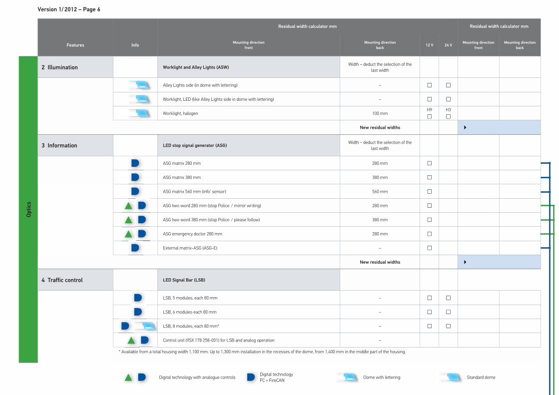
Version 1/ 2012 – Page 6
Residual width calculator mm Residual width calculator mm
Features InfoMounting direction
front
Mounting direction
back12 V 24 V
Mounting direction
front
Mounting direction
back
Op
tics
2 Illumination Worklight and Alley Lights (ASW) Width – deduct the selection of the
last width
Alley Lights side (in dome with lettering) – � �
Worklight, LED (like Alley Lights side in dome with lettering) – � �
Worklight, halogen 100 mmH9�
H3�
New residual widths �
3 Information LED stop signal generator (ASG)Width – deduct the selection of the
last width
ASG matrix 280 mm 280 mm �
ASG matrix 380 mm 380 mm �
ASG matrix 560 mm (info' sensor) 560 mm �
ASG two-word 280 mm (stop Police / mirror writing) 280 mm �
ASG two-word 380 mm (stop Police / please follow) 380 mm �
ASG emergency doctor 280 mm 280 mm �
External matrix-ASG (ASG-E) – �
New residual widths �
4 Traffic control LED Signal Bar (LSB)
LSB, 5 modules, each 80 mm – � �
LSB, 6 modules each 80 mm – � �
LSB, 8 modules, each 80 mm* – � �
Control unit (9SX 178 258-001) for LSB and analog operation –
* Available from a total housing width 1,100 mm. Up to 1,300 mm installation in the recesses of the dome, from 1,400 mm in the middle part of the housing.
Digital technology with analogue controls Digital technology FC = FireCAN Dome with lettering Standard dome
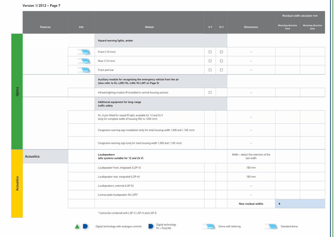
Version 1/ 2012 – Page 7
Residual width calculator mm
Features Info Module 12 V 24 V DimensionsMounting direction
front
Mounting direction
back
Op
tics
Hazard warning lights, amber
Front (110 mm) � � –
Rear (110 mm) � � –
Front and rear � � –
Auxiliary module for recognising the emergency vehicle from the air
(also refer to KL-LM5 / KL-LM6 / Kl-LM7 on Page 5)
Infrared lighting module IR (installed in central housing section) � –
Additional equipment for long-range
traffic safety
KL-A pre-fitted for raised ID light, available for 12 and 24 V(only for complete width of housing 900 to 1200 mm) –
Congestion warning sign installation (only for total housing width 1,000 and 1,100 mm) –
Congestion warning sign (only for total housing width 1,000 and 1,100 mm) –
Aco
usti
cs
AcousticsLoudspeakers
(alls systems suitable for 12 and 24 V)
Width – deduct the selection of the last width
Loudspeaker front, integrated (LSP-V) 180 mm
Loudspeaker rear, integrated (LSP-H) 180 mm
Loudspeakers, external (LSP-E) –
License plate loudspeaker (N-LSP)* –
New residual widths �
* Cannot be combined with LSP-V, LSP-H and LSP-E.
Digital technology with analogue controls Digital technology FC = FireCAN Dome with lettering Standard dome
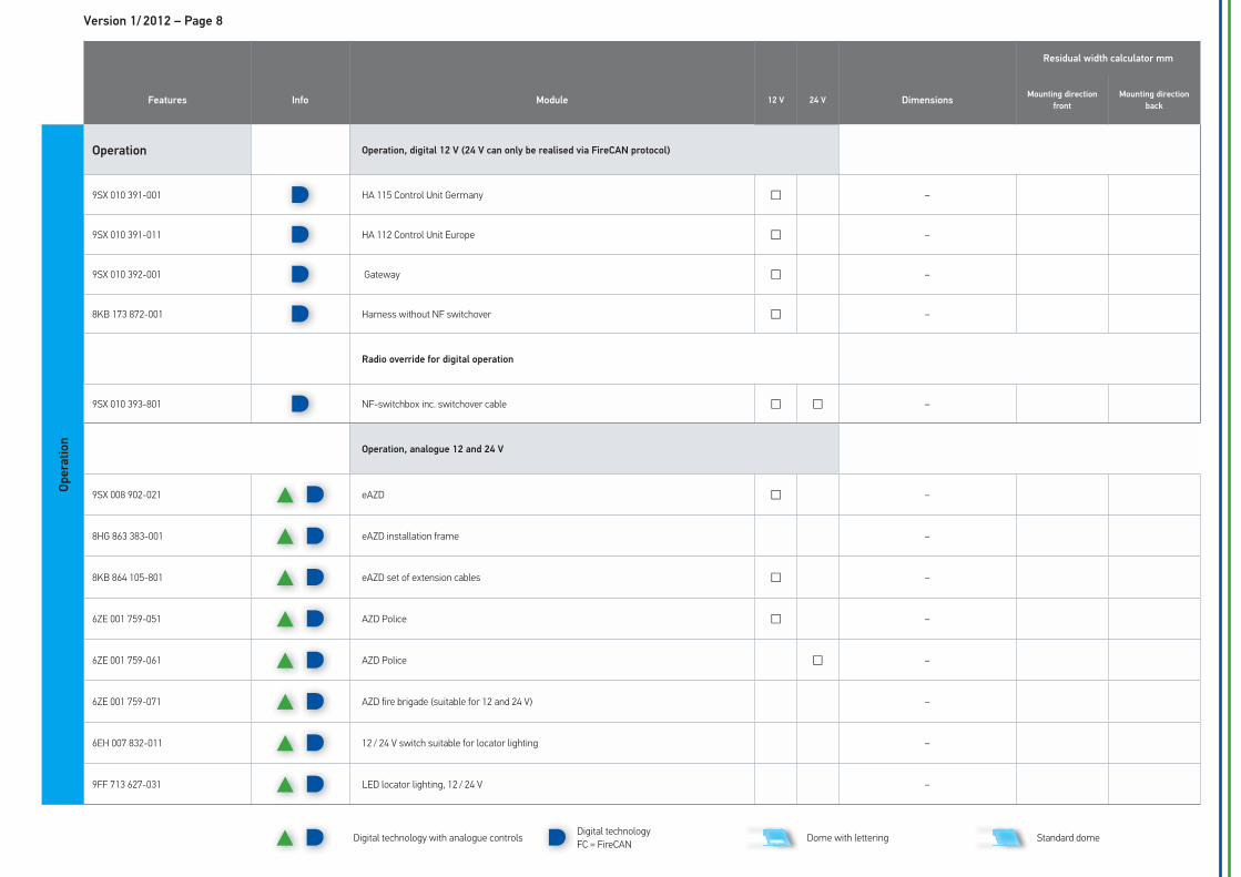
Version 1/ 2012 – Page 8
Residual width calculator mm
Features Info Module 12 V 24 V DimensionsMounting direction
front
Mounting direction
back
Op
era
tio
n
Operation Operation, digital 12 V (24 V can only be realised via FireCAN protocol)
9SX 010 391-001 HA 115 Control Unit Germany � –
9SX 010 391-011 HA 112 Control Unit Europe � –
9SX 010 392-001 Gateway � –
8KB 173 872-001 Harness without NF switchover � –
Radio override for digital operation
9SX 010 393-801 NF-switchbox inc. switchover cable � � –
Operation, analogue 12 and 24 V
9SX 008 902-021 eAZD � –
8HG 863 383-001 eAZD installation frame –
8KB 864 105-801 eAZD set of extension cables � –
6ZE 001 759-051 AZD Police � –
6ZE 001 759-061 AZD Police � –
6ZE 001 759-071 AZD fire brigade (suitable for 12 and 24 V) –
6EH 007 832-011 12 / 24 V switch suitable for locator lighting –
9FF 713 627-031 LED locator lighting, 12 / 24 V –
Digital technology with analogue controls Digital technology FC = FireCAN Dome with lettering Standard dome
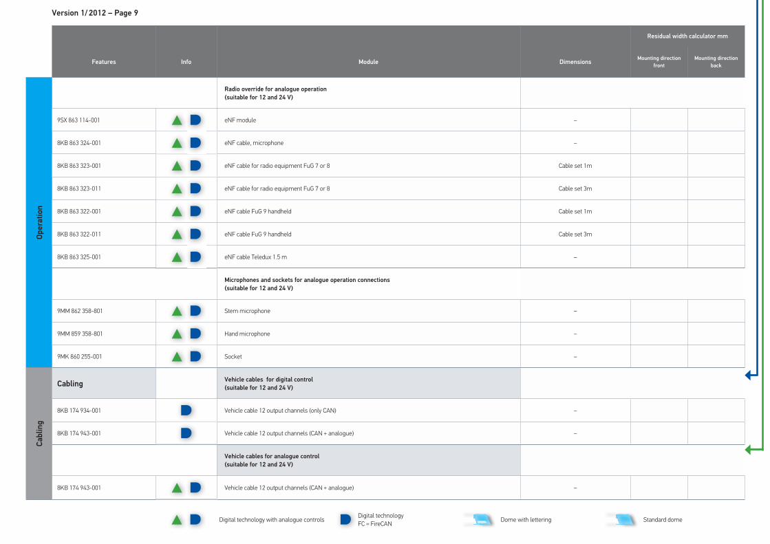
Version 1/ 2012 – Page 9
Residual width calculator mm
Features Info Module DimensionsMounting direction
front
Mounting direction
back
Op
era
tio
n
Radio override for analogue operation
(suitable for 12 and 24 V)
9SX 863 114-001 eNF module –
8KB 863 324-001 eNF cable, microphone –
8KB 863 323-001 eNF cable for radio equipment FuG 7 or 8 Cable set 1m
8KB 863 323-011 eNF cable for radio equipment FuG 7 or 8 Cable set 3m
8KB 863 322-001 eNF cable FuG 9 handheld Cable set 1m
8KB 863 322-011 eNF cable FuG 9 handheld Cable set 3m
8KB 863 325-001 eNF cable Teledux 1.5 m –
Microphones and sockets for analogue operation connections
(suitable for 12 and 24 V)
9MM 862 358-801 Stem microphone –
9MM 859 358-801 Hand microphone –
9MK 860 255-001 Socket –
Cab
lin
g
CablingVehicle cables for digital control
(suitable for 12 and 24 V)
8KB 174 934-001 Vehicle cable 12 output channels (only CAN) –
8KB 174 943-001 Vehicle cable 12 output channels (CAN + analogue) –
Vehicle cables for analogue control
(suitable for 12 and 24 V)
8KB 174 943-001 Vehicle cable 12 output channels (CAN + analogue) –
Digital technology with analogue controls Digital technology
FC = FireCAN Dome with lettering Standard dome
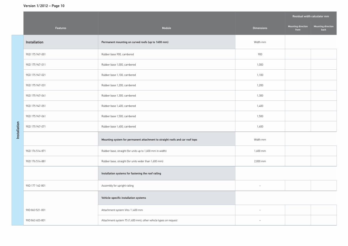
Version 1/ 2012 – Page 10
Residual width calculator mm
Features Module DimensionsMounting direction
front
Mounting direction
back
Insta
llati
on
Installation Permanent mounting on curved roofs (up to 1600 mm) Width mm
9GD 175 947-001 Rubber base 900, cambered 900
9GD 175 947-011 Rubber base 1,000, cambered 1,000
9GD 175 947-021 Rubber base 1,100, cambered 1,100
9GD 175 947-031 Rubber base 1,200, cambered 1,200
9GD 175 947-041 Rubber base 1,300, cambered 1,300
9GD 175 947-051 Rubber base 1,400, cambered 1,400
9GD 175 947-061 Rubber base 1,500, cambered 1,500
9GD 175 947-071 Rubber base 1,600, cambered 1,600
Mounting system for permanent attachment to straight roofs and car roof tops Width mm
9GD 176 514-871 Rubber base, straight (for units up to 1,600 mm in width) 1,600 mm
9GD 176 514-881 Rubber base, straight (for units wider than 1,600 mm) 2,000 mm
Installation systems for fastening the roof railing
9XD 177 162-801 Assembly for upright railing –
Vehicle-specific installation systems
9XD 863 521-001 Attachment system Vito / 1,400 mm –
9XD 863 403-801 Attachment system T5 (1,400 mm), other vehicle types on request –
You will find the order form on the following page.
Simply mark the modules and components you want with a cross and send the form to
HELLA.
Version 1/ 2012 – Page 12
Country code
D / GB / F / E / I …
Page 4
Basic definition
Vehicle electrical system voltage □ 12 V □ 24 V
Housing □ 900 mm / 360 mm □ 1000 mm / 460 mm □ 1100 mm / 560 mm □ 1200 mm / 660 mm □ 1300 mm / 760 mm □ 1400 mm / 860 mm
□ 1500 mm / 960 mm □ 1600 mm / 1060 mm □ 1700 mm / 1160 mm □ 1800 mm / 1260 mm □ 1900 mm / 1360 mm □ 2000 mm / 1460 mm
Page 5 – 7
Optic systems
Signals:
Main beacon module
□ KL-LM2, blue □ KL-LM2, yellow □ KL-LM3, blue and yellow (on request)
□ KL-LM4, blue □ KL-LM4, yellow □ KL-LM5, blue □ KL-LM6, blue
□ KL-LM7, blue □ KL-LR2, blue □ KL-LR2, red □ KL-LR2, yellow □ KL-ER, blue □ KL-ER, red □ KL-ER, yellow
Signals:
Long-range flash module
□ BSF-LED / 80 mm □ BSF-LED with red stop light / 80 mm
□ Individual red stop light module / 80 mm
Illumination:
Worklight and Alley Lights
□ Alley Lights side □ LED worklights □ Worklights, halogen/ 100 mm
Traffic control:
LED stop signal generator ASG □ ASG matrix 280 mm □ ASG matrix 380 mm □ ASG matrix 560 mm
□ ASG two-word 280 mm (STOP POLICE, mirrored text)
□ ASG two-word 380 mm
Stop Police / Please Follow
□ ASG emergency doctor
280 mm□ External matrix-ASG
Information:
LED Signal Bar (LSB) □ LSB / 5 modules à 80 mm
□ LSB / 6 modules à 80 mm
□ LSB / 8 modules à 80 mm
□ LSB in connection with the operating unit (operating unit should be ordered separately)
Information:
Hazard warning lights, amber □ Front / 110 mm □ Rear / 110 mm □ Front and rear
Auxiliary module for recognising the
emergency vehicle from the air
□ Infrared light modulein middle part of housing
Additional equipment for long-range
traffic safety
□ KL-A setup / 900 –1,200 mm
□ Congestion warning sign installation / 1,100 mm
□ Congestion warning sign / 1,100 mm
Page 7
Acoustics
Loudspeakers □ Loudspeaker front, integrated / 180 mm
□ Loudspeaker rear, integrated / 180 mm
□ Loudspeakers, external □ Licence plate loudspeaker
RTK7 Order form Please enter the country code, place a cross in the white fields for the required components � and then send it to HELLA.
�
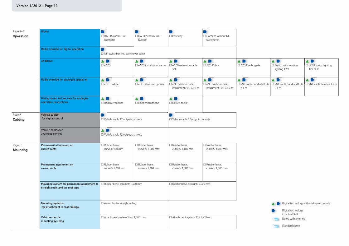
Version 1/ 2012 – Page 13
Page 8 – 9
Operation
Digital
□ HA 115 control unit Germany
□ HA 112 control unit Europe
□ Gateway □ Harness without NF switchover
Radio override for digital operation
□ NF-switchbox inc. switchover cable
Analogue □ eAZD
□ eAZD installation frame
□ eAZD extension cable
set
□ AZD Police
□ AZD Fire brigade
□ Switch with location
lighting 12 V
□ LED locator lighting,
12 / 24 V
Radio override for analogue operation □ eNF module
□ eNF cable microphone
□ eNF cable for radio
equipment FuG 7.8 3 m
□ eNF cable for radio
equipment FuG 7.8 3 m
□ eNF cable handheld FuG
9 1 m
□ eNF cable handheld FuG
9 3 m
□ eNF cable Teledux 1.5 m
Microphones and sockets for analogue
operation connections
□ Rod microphone
□ Hand microphone
□ Device socket
Page 9
Cabling
Vehicle cables
for digital control □ Vehicle cable 12 output channels □ Vehicle cable 12 output channels
Vehicle cables for
analogue control
□ Vehicle cable 12 output channels
Page 10
Mounting
Permanent attachment on
curved roofs
□ Rubber base, curved/ 900 mm
□ Rubber base, curved/ 1,000 mm
□ Rubber base, curved/ 1,100 mm
□ Rubber base, curved/ 1,200 mm
Permanent attachment on
curved roofs
□ Rubber base, curved/ 1,300 mm
□ Rubber base, curved/ 1,400 mm
□ Rubber base, curved/ 1,500 mm
□ Rubber base, curved/ 1,600 mm
Mounting system for permanent attachment to
straight roofs and car roof tops
□ Rubber base, straight/ 1,600 mm □ Rubber base, straight/ 2,000 mm
Mounting systems
for attachment to roof railings
□ Assembly for upright railing
Vehicle-specific
mounting systems
□ Attachment system Vito / 1,400 mm □ Attachment system T5 / 1,400 mm
Digital technology with analogue controls
Digital technologyFC = FireCANDome with lettering
Standard dome
Version 1/ 2012 – Page 14
RTK7 overview of accessories
Licence plate*1x 9MM 010 657-001
Yes
No
Gateway9SX 010 392-101
NF switch9SX 010 393-801
HA 1159SX 010 391-001
Cable8KB 173 872-001
HA 1159SX 010 391-001
AZD Fire brigade6ZE 001 759-071
AZD Police6ZE 001 759-051 12 V6ZE 001 759-061 24 V
eAZD9SX 008 902-021
Frame8GH 863 383-001
Individual switch6EH 007 832-011
NF switch9SX 010 393-801
With voice messages
Socket9MK 860 255-001
Hand set9MM 859 358-801
Vehicle cable, digital
8KB 174 934-001
Vehicle cable, analogue
8KB 174 943-001
Rubber seal
Fixed, flat1,600 mm /
9GD 176 514-8812,000 mm /
9GD 176 514-871
Railing9XD 177 162-801
Digital technology with analogue controls
Digital technologyFC = FireCAN
Example order
Selection possibilities
Rubber base
Fixed, curved900 mm / 9GD 175 947-001
1,000 mm / 9GD 175 947-0111,100 mm / 9GD 175 947-0211,400 mm / 9GD 175 947-0511,500 mm / 9GD 175 947-0611,600 mm / 9GD 175 947-071
Operation
Gateway9SX 010 392-001
Fixing
external (LSP-E)2x 9MM 863 164-051
Type
With radio override
**
* When the N-LSP is used, the RTK7 must be configured accordingly.** Analogue operation is not available with Matrix ASG or LSB.
Lo
ud
sp
eak
ers
internal (LSP-V
and /or LSP-H)1x 9MM 010 657-001
No
**
HELLA KGaA Hueck & Co.
Rixbecker Straße 7559552 Lippstadt, GermanyTel.: +49 2941 38-0Fax: +49 2941 38-7133Internet: www.hella.com
© HELLA KGaA Hueck & Co., Lippstadt, 05.12