Embed Size (px)
Citation preview
Orbitrap Tribrid SeriesHardware Manual
80000-97027 Revision A June 2018

© 2018 Thermo Fisher Scientific Inc. All rights reserved.
Automatic Gain Control, EASY-ETD, EASY-IC, EASY-Max NG, Fusion, ID-X, Lumos, OptaMax NG, and Orbitrap ID-X are trademarks; Unity is a registered service mark; and Hypersil GOLD AQ, Orbitrap, Orbitrap Fusion, Orbitrap Fusion Lumos, Pierce, Thermo Scientific, Tribrid, and Xcalibur are registered trademarks of Thermo Fisher Scientific Inc. in the United States. Fisher Scientific is a registered trademark of Fisher Scientific Co. in the United States.
The following are registered trademarks in the United States and other countries: COMBICON is a registered trademark of Phoenix Contact GmbH & Co. Microsoft and Windows are registered trademarks of Microsoft Corporation. Teflon is a registered trademark of E.I. du Pont de Nemours & Co.
The following are registered trademarks in the United States and possibly other countries: Liquinox is a registered trademark of Alconox, Inc. MICRO-MESH is a registered trademark of Micro-Surface Finishing Products, Inc. Nalgene is a registered trademark of Nalge Nunc International Corporation. Oerlikon Leybold Vacuum is a registered trademark of OC Oerlikon Corporation AG. Rheodyne is a registered trademark of IDEX Health & Science, LLC. SOGEVAC is a registered trademark of Oerlikon Leybold Vacuum. Swagelok is a registered trademark of Swagelok Company. Tygon is a registered trademark of the division of Saint-Gobain Performance Plastics Corporation. Upchurch Scientific is a registered trademark of IDEX Health & Science LLC. Vespel is a registered trademark of E.I. du Pont de Nemours & Co. Viton is a registered trademark of DuPont Performance Elastomers LLC.
Chemyx is a trademark of Chemyx Inc. MX Series II is a trademark of IDEX Health & Science, LLC.
All other trademarks are the property of Thermo Fisher Scientific Inc. and its subsidiaries.
Thermo Fisher Scientific Inc. provides this document to its customers with a product purchase to use in the product operation. This document is copyright protected and any reproduction of the whole or any part of this document is strictly prohibited, except with the written authorization of Thermo Fisher Scientific Inc.
The contents of this document are subject to change without notice. All technical information in this document is for reference purposes only. System configurations and specifications in this document supersede all previous information received by the purchaser.
This document is not part of any sales contract between Thermo Fisher Scientific Inc. and a purchaser. This document shall in no way govern or modify any Terms and Conditions of Sale, which Terms and Conditions of Sale shall govern all conflicting information between the two documents.
Release history: Rev A, June 2018
Software version: (Thermo) Foundation 3.1 SP5 and later, Xcalibur 4.2 and later, Tune 3.1 and later
For Research Use Only. Not for use in diagnostic procedures.
Regulatory Compliance
Thermo Fisher Scientific performs complete testing and evaluation of its products to ensure full compliance with applicable North American and European regulations. Your system meets the applicable requirements in the electromagnetic compatibility (EMC) and product safety standards described in this section.
Unauthorized changes that you make to your system will void regulatory compliance and may defeat the built-in protections for your instrument. Some examples of unauthorized changes include using replacement parts or adding components, options, or peripherals that Thermo Fisher Scientific has not qualified and authorized. Unauthorized changes can also result in bodily injury and/or damage to your system and laboratory.
Ensure continued compliance with regulatory standards:• Follow all installation instructions provided in the documentation that comes with your system.• Order replacement parts (as specified in the instrument manual) and additional components, options, and periph-
erals directly from Thermo Fisher Scientific or an authorized representative.
Regulatory compliance results for the following Thermo Scientific™ mass spectrometers: • Orbitrap Fusion Lumos• Orbitrap Fusion and Orbitrap ID-X
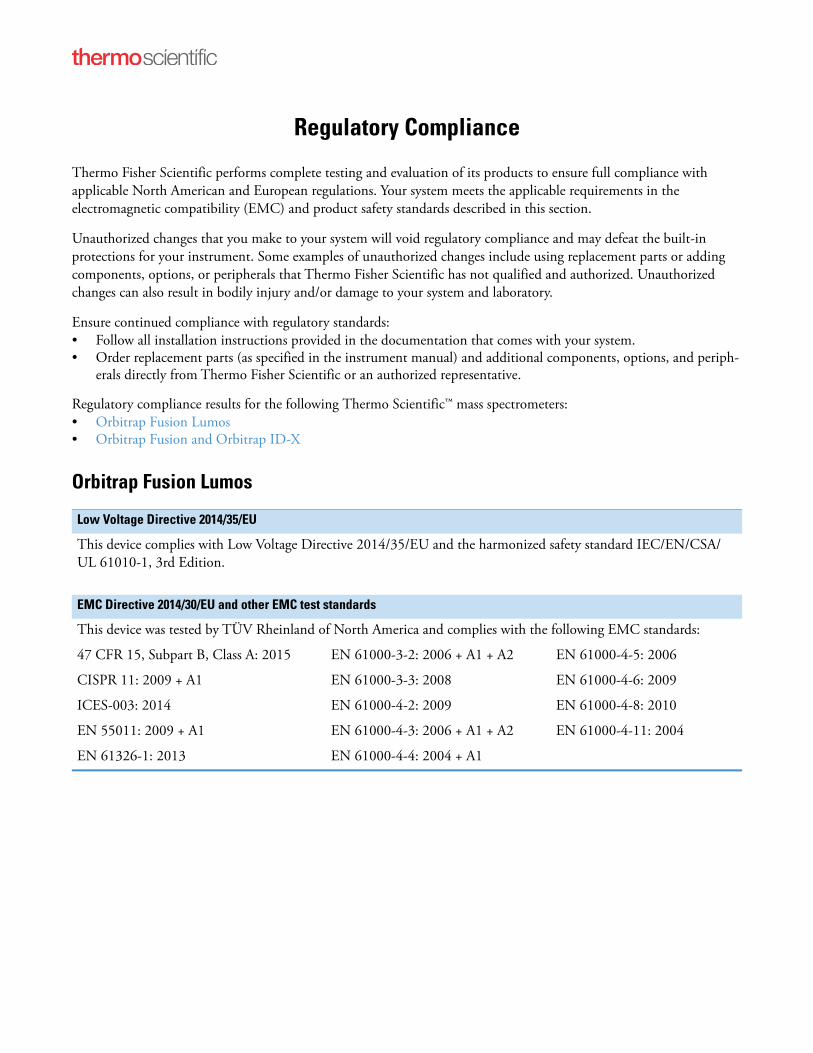
Orbitrap Fusion Lumos
Low Voltage Directive 2014/35/EU
This device complies with Low Voltage Directive 2014/35/EU and the harmonized safety standard IEC/EN/CSA/ UL 61010-1, 3rd Edition.
EMC Directive 2014/30/EU and other EMC test standards
This device was tested by TÜV Rheinland of North America and complies with the following EMC standards:
47 CFR 15, Subpart B, Class A: 2015 EN 61000-3-2: 2006 + A1 + A2 EN 61000-4-5: 2006
CISPR 11: 2009 + A1 EN 61000-3-3: 2008 EN 61000-4-6: 2009
ICES-003: 2014 EN 61000-4-2: 2009 EN 61000-4-8: 2010
EN 55011: 2009 + A1 EN 61000-4-3: 2006 + A1 + A2 EN 61000-4-11: 2004
EN 61326-1: 2013 EN 61000-4-4: 2004 + A1
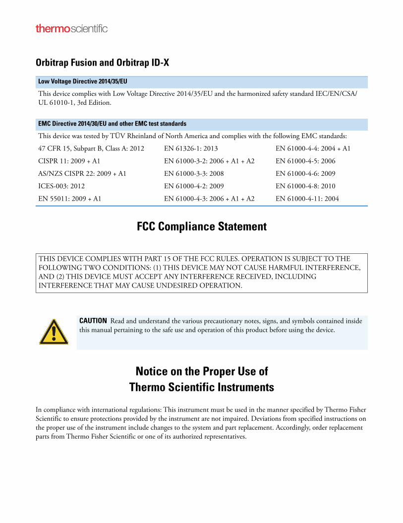
Orbitrap Fusion and Orbitrap ID-X
FCC Compliance Statement
Notice on the Proper Use ofThermo Scientific Instruments
In compliance with international regulations: This instrument must be used in the manner specified by Thermo Fisher Scientific to ensure protections provided by the instrument are not impaired. Deviations from specified instructions on the proper use of the instrument include changes to the system and part replacement. Accordingly, order replacement parts from Thermo Fisher Scientific or one of its authorized representatives.
Low Voltage Directive 2014/35/EU
This device complies with Low Voltage Directive 2014/35/EU and the harmonized safety standard IEC/EN/CSA/ UL 61010-1, 3rd Edition.
EMC Directive 2014/30/EU and other EMC test standards
This device was tested by TÜV Rheinland of North America and complies with the following EMC standards:
47 CFR 15, Subpart B, Class A: 2012 EN 61326-1: 2013 EN 61000-4-4: 2004 + A1
CISPR 11: 2009 + A1 EN 61000-3-2: 2006 + A1 + A2 EN 61000-4-5: 2006
AS/NZS CISPR 22: 2009 + A1 EN 61000-3-3: 2008 EN 61000-4-6: 2009
ICES-003: 2012 EN 61000-4-2: 2009 EN 61000-4-8: 2010
EN 55011: 2009 + A1 EN 61000-4-3: 2006 + A1 + A2 EN 61000-4-11: 2004
THIS DEVICE COMPLIES WITH PART 15 OF THE FCC RULES. OPERATION IS SUBJECT TO THE FOLLOWING TWO CONDITIONS: (1) THIS DEVICE MAY NOT CAUSE HARMFUL INTERFERENCE, AND (2) THIS DEVICE MUST ACCEPT ANY INTERFERENCE RECEIVED, INCLUDING INTERFERENCE THAT MAY CAUSE UNDESIRED OPERATION.
CAUTION Read and understand the various precautionary notes, signs, and symbols contained inside this manual pertaining to the safe use and operation of this product before using the device.
WEEE Directive2012/19/EU
Thermo Fisher Scientific is registered with B2B Compliance (B2Bcompliance.org.uk) in the UK and with the European Recycling Platform (ERP-recycling.org) in all other countries of the European Union and in Norway.
If this product is located in Europe and you want to participate in the Thermo Fisher Scientific Business-to-Business (B2B) Recycling Program, send an email request to [email protected] with the following information:
• WEEE product class
• Name of the manufacturer or distributor (where you purchased the product)
• Number of product pieces, and the estimated total weight and volume
• Pick-up address and contact person (include contact information)
• Appropriate pick-up time
• Declaration of decontamination, stating that all hazardous fluids or material have been removed from the product
For additional information about the Restriction on Hazardous Substances (RoHS) Directive for the European Union, search for RoHS on the Thermo Fisher Scientific European language websites.
IMPORTANT This recycling program is not for biological hazard products or for products that have been medically contaminated. You must treat these types of products as biohazard waste and dispose of them in accordance with your local regulations.

Thermo Scientific Orbitrap Tribrid Series Hardware Manual vii
C
Preface . . . . . . . . . . . . . . . . . . . . . . . . . . . . . . . . . . . . . . . . . . . . . . . . . . . . . . . . . . . . .xiiiAccessing Documentation. . . . . . . . . . . . . . . . . . . . . . . . . . . . . . . . . . . . . . . . .xiii
Viewing the Product Manuals . . . . . . . . . . . . . . . . . . . . . . . . . . . . . . . . . . . .xivAccessing the Help Menu Options . . . . . . . . . . . . . . . . . . . . . . . . . . . . . . . .xivViewing Online User Documentation . . . . . . . . . . . . . . . . . . . . . . . . . . . . . .xiv
Providing Documentation Feedback. . . . . . . . . . . . . . . . . . . . . . . . . . . . . . . . . xvLicense for the 1M Option . . . . . . . . . . . . . . . . . . . . . . . . . . . . . . . . . . . . . . . . xvSpecial Notices, Symbols, and Cautions . . . . . . . . . . . . . . . . . . . . . . . . . . . . . . xvModel Differences . . . . . . . . . . . . . . . . . . . . . . . . . . . . . . . . . . . . . . . . . . . . . xviiContacting Us . . . . . . . . . . . . . . . . . . . . . . . . . . . . . . . . . . . . . . . . . . . . . . . .xviii
Chapter 1 Introduction . . . . . . . . . . . . . . . . . . . . . . . . . . . . . . . . . . . . . . . . . . . . . . . . . . . . . . . . . . .1Orbitrap Tribrid Series Mass Spectrometers . . . . . . . . . . . . . . . . . . . . . . . . . . . . 1Overview of an LC/MS Analysis . . . . . . . . . . . . . . . . . . . . . . . . . . . . . . . . . . . . . 3LC/MS Functional Block Diagram . . . . . . . . . . . . . . . . . . . . . . . . . . . . . . . . . . . 5Electronic Assemblies . . . . . . . . . . . . . . . . . . . . . . . . . . . . . . . . . . . . . . . . . . . . . 5Controls and Indicators . . . . . . . . . . . . . . . . . . . . . . . . . . . . . . . . . . . . . . . . . . . . 6
LEDs. . . . . . . . . . . . . . . . . . . . . . . . . . . . . . . . . . . . . . . . . . . . . . . . . . . . . . . . 6Power Entry Module . . . . . . . . . . . . . . . . . . . . . . . . . . . . . . . . . . . . . . . . . . . . 7Communications Panel . . . . . . . . . . . . . . . . . . . . . . . . . . . . . . . . . . . . . . . . . . 8
Cooling Fans . . . . . . . . . . . . . . . . . . . . . . . . . . . . . . . . . . . . . . . . . . . . . . . . . . . 10
Chapter 2 Scan Parameters . . . . . . . . . . . . . . . . . . . . . . . . . . . . . . . . . . . . . . . . . . . . . . . . . . . . . .11Scan Types . . . . . . . . . . . . . . . . . . . . . . . . . . . . . . . . . . . . . . . . . . . . . . . . . . . . 11
MS Scan . . . . . . . . . . . . . . . . . . . . . . . . . . . . . . . . . . . . . . . . . . . . . . . . . . . . 11MS2 Scan and MSn Scan . . . . . . . . . . . . . . . . . . . . . . . . . . . . . . . . . . . . . . . . 12SIM Scan. . . . . . . . . . . . . . . . . . . . . . . . . . . . . . . . . . . . . . . . . . . . . . . . . . . . 12
Scan Rates for the Ion Trap Detector . . . . . . . . . . . . . . . . . . . . . . . . . . . . . . . . 12Scan Mass-To-Charge Ratio Ranges . . . . . . . . . . . . . . . . . . . . . . . . . . . . . . . . . 13Resolutions for the Orbitrap Detector . . . . . . . . . . . . . . . . . . . . . . . . . . . . . . . . 13Data Types . . . . . . . . . . . . . . . . . . . . . . . . . . . . . . . . . . . . . . . . . . . . . . . . . . . . 14Ion Polarity Modes . . . . . . . . . . . . . . . . . . . . . . . . . . . . . . . . . . . . . . . . . . . . . . 14
Contents
Contents
viii Orbitrap Tribrid Series Hardware Manual Thermo Scientific
Chapter 3 Vacuum System . . . . . . . . . . . . . . . . . . . . . . . . . . . . . . . . . . . . . . . . . . . . . . . . . . . . . . .15Vacuum System Functional Block Diagram . . . . . . . . . . . . . . . . . . . . . . . . . . . 15Schematic of the Internal Gas Supply Lines. . . . . . . . . . . . . . . . . . . . . . . . . . . . 17Inlet Gases Hardware . . . . . . . . . . . . . . . . . . . . . . . . . . . . . . . . . . . . . . . . . . . . 18
Helium Regulator . . . . . . . . . . . . . . . . . . . . . . . . . . . . . . . . . . . . . . . . . . . . . 19Nitrogen Gas Valves . . . . . . . . . . . . . . . . . . . . . . . . . . . . . . . . . . . . . . . . . . . 19Vent Valve. . . . . . . . . . . . . . . . . . . . . . . . . . . . . . . . . . . . . . . . . . . . . . . . . . . 20
Vacuum Manifold . . . . . . . . . . . . . . . . . . . . . . . . . . . . . . . . . . . . . . . . . . . . . . . 20Vacuum Gauges . . . . . . . . . . . . . . . . . . . . . . . . . . . . . . . . . . . . . . . . . . . . . . . . 21Vacuum Pumps. . . . . . . . . . . . . . . . . . . . . . . . . . . . . . . . . . . . . . . . . . . . . . . . . 21Atmospheric Pressure Ionization Source . . . . . . . . . . . . . . . . . . . . . . . . . . . . . . 23API Source Interface . . . . . . . . . . . . . . . . . . . . . . . . . . . . . . . . . . . . . . . . . . . . . 24
Chapter 4 Ion Transmission and Mass Analysis . . . . . . . . . . . . . . . . . . . . . . . . . . . . . . . . . . . .27Workflow for Mass Analysis . . . . . . . . . . . . . . . . . . . . . . . . . . . . . . . . . . . . . . . 27Ion Optics . . . . . . . . . . . . . . . . . . . . . . . . . . . . . . . . . . . . . . . . . . . . . . . . . . . . . 29
MP00 Ion Optics . . . . . . . . . . . . . . . . . . . . . . . . . . . . . . . . . . . . . . . . . . . . . 30MP0 Ion Optics . . . . . . . . . . . . . . . . . . . . . . . . . . . . . . . . . . . . . . . . . . . . . . 31MP1 Ion Optics . . . . . . . . . . . . . . . . . . . . . . . . . . . . . . . . . . . . . . . . . . . . . . 32Curved Linear Trap. . . . . . . . . . . . . . . . . . . . . . . . . . . . . . . . . . . . . . . . . . . . 32Ion-Routing Multipole . . . . . . . . . . . . . . . . . . . . . . . . . . . . . . . . . . . . . . . . . 33MP3 Ion Optics . . . . . . . . . . . . . . . . . . . . . . . . . . . . . . . . . . . . . . . . . . . . . . 33DC Offset Voltages . . . . . . . . . . . . . . . . . . . . . . . . . . . . . . . . . . . . . . . . . . . . 34
Mass Analyzers . . . . . . . . . . . . . . . . . . . . . . . . . . . . . . . . . . . . . . . . . . . . . . . . . 34Quadrupole Mass Analyzer . . . . . . . . . . . . . . . . . . . . . . . . . . . . . . . . . . . . . . 34Orbitrap Mass Analyzer . . . . . . . . . . . . . . . . . . . . . . . . . . . . . . . . . . . . . . . . . 36Linear Ion Trap Mass Analyzer . . . . . . . . . . . . . . . . . . . . . . . . . . . . . . . . . . . 39
Ion Detection Systems. . . . . . . . . . . . . . . . . . . . . . . . . . . . . . . . . . . . . . . . . . . . 42
Chapter 5 Syringe Pump and Divert/Inject Valve . . . . . . . . . . . . . . . . . . . . . . . . . . . . . . . . . . .43Syringe Pump . . . . . . . . . . . . . . . . . . . . . . . . . . . . . . . . . . . . . . . . . . . . . . . . . . 43Divert/Inject Valve . . . . . . . . . . . . . . . . . . . . . . . . . . . . . . . . . . . . . . . . . . . . . . 44
Configurations . . . . . . . . . . . . . . . . . . . . . . . . . . . . . . . . . . . . . . . . . . . . . . . 45Controlling the Divert/Inject Valve . . . . . . . . . . . . . . . . . . . . . . . . . . . . . . . . 46
Chapter 6 System Shutdown, Startup, and Reset . . . . . . . . . . . . . . . . . . . . . . . . . . . . . . . . . . .47Shutting Down the System in an Emergency. . . . . . . . . . . . . . . . . . . . . . . . . . . 47Placing the Mass Spectrometer in Standby Mode . . . . . . . . . . . . . . . . . . . . . . . 48Turning On the Mass Spectrometer . . . . . . . . . . . . . . . . . . . . . . . . . . . . . . . . . 48Shutting Down the Mass Spectrometer System Completely . . . . . . . . . . . . . . . 48Starting the System after a Complete Shutdown . . . . . . . . . . . . . . . . . . . . . . . . 50
Starting the LC System . . . . . . . . . . . . . . . . . . . . . . . . . . . . . . . . . . . . . . . . . 50Starting the Data System . . . . . . . . . . . . . . . . . . . . . . . . . . . . . . . . . . . . . . . . 50Starting the Mass Spectrometer . . . . . . . . . . . . . . . . . . . . . . . . . . . . . . . . . . . 50Starting the Autosampler . . . . . . . . . . . . . . . . . . . . . . . . . . . . . . . . . . . . . . . . 51
Contents
Thermo Scientific Orbitrap Tribrid Series Hardware Manual ix
Resetting the Mass Spectrometer . . . . . . . . . . . . . . . . . . . . . . . . . . . . . . . . . . . . 52Resetting Calibration Parameters. . . . . . . . . . . . . . . . . . . . . . . . . . . . . . . . . . . . 52Restarting the Data System . . . . . . . . . . . . . . . . . . . . . . . . . . . . . . . . . . . . . . . . 53On/Off Status for MS Components Under Varying Power Conditions. . . . . . . 54
Chapter 7 Daily Operation . . . . . . . . . . . . . . . . . . . . . . . . . . . . . . . . . . . . . . . . . . . . . . . . . . . . . . .57Before Operating the Orbitrap Tribrid Series System . . . . . . . . . . . . . . . . . . . . 58
Checking the System Mode . . . . . . . . . . . . . . . . . . . . . . . . . . . . . . . . . . . . . . 58Checking the Vacuum Pressure Levels . . . . . . . . . . . . . . . . . . . . . . . . . . . . . . 58Checking the Gas Supplies . . . . . . . . . . . . . . . . . . . . . . . . . . . . . . . . . . . . . . 59
After Operating the Orbitrap Tribrid Series System . . . . . . . . . . . . . . . . . . . . . 59Flushing the Inlet Components . . . . . . . . . . . . . . . . . . . . . . . . . . . . . . . . . . . 60Purging the Oil in the Forepump . . . . . . . . . . . . . . . . . . . . . . . . . . . . . . . . . 61Emptying the Solvent Waste Container. . . . . . . . . . . . . . . . . . . . . . . . . . . . . 61Placing the System in Standby Mode. . . . . . . . . . . . . . . . . . . . . . . . . . . . . . . 61
Chapter 8 Maintenance . . . . . . . . . . . . . . . . . . . . . . . . . . . . . . . . . . . . . . . . . . . . . . . . . . . . . . . . .63Maintenance Schedule. . . . . . . . . . . . . . . . . . . . . . . . . . . . . . . . . . . . . . . . . . . . 64Guidelines . . . . . . . . . . . . . . . . . . . . . . . . . . . . . . . . . . . . . . . . . . . . . . . . . . . . . 65Tools and Supplies . . . . . . . . . . . . . . . . . . . . . . . . . . . . . . . . . . . . . . . . . . . . . . 65Maintaining the API Source Housing . . . . . . . . . . . . . . . . . . . . . . . . . . . . . . . . 67Maintaining the API Source Interface . . . . . . . . . . . . . . . . . . . . . . . . . . . . . . . . 68
Cleaning the Ion Sweep Cone, Spray Cone, and Ion Transfer Tube . . . . . . . 68Removing the API Source Interface . . . . . . . . . . . . . . . . . . . . . . . . . . . . . . . . 73Cleaning the RF Lens, Exit Lens, MP00 RF Lens, and Lens L0. . . . . . . . . . . 74Reinstalling the API Source Interface. . . . . . . . . . . . . . . . . . . . . . . . . . . . . . . 78
Maintaining the Forepump . . . . . . . . . . . . . . . . . . . . . . . . . . . . . . . . . . . . . . . . 78Maintaining the Air Filter . . . . . . . . . . . . . . . . . . . . . . . . . . . . . . . . . . . . . . . . . 79Pumping Down the Mass Spectrometer . . . . . . . . . . . . . . . . . . . . . . . . . . . . . . 79
Chapter 9 Replaceable Parts. . . . . . . . . . . . . . . . . . . . . . . . . . . . . . . . . . . . . . . . . . . . . . . . . . . . .83Orbitrap Tribrid Series Chemicals Kit. . . . . . . . . . . . . . . . . . . . . . . . . . . . . . . . 83Calibration Kit . . . . . . . . . . . . . . . . . . . . . . . . . . . . . . . . . . . . . . . . . . . . . . . . . 84MS Setup Kit . . . . . . . . . . . . . . . . . . . . . . . . . . . . . . . . . . . . . . . . . . . . . . . . . . 85Performance Specification Kit . . . . . . . . . . . . . . . . . . . . . . . . . . . . . . . . . . . . . . 85Single Mechanical Pump Kit . . . . . . . . . . . . . . . . . . . . . . . . . . . . . . . . . . . . . . . 86Dual Mechanical Pumps Kit . . . . . . . . . . . . . . . . . . . . . . . . . . . . . . . . . . . . . . . 86API Source Interface . . . . . . . . . . . . . . . . . . . . . . . . . . . . . . . . . . . . . . . . . . . . . 87Miscellaneous Parts . . . . . . . . . . . . . . . . . . . . . . . . . . . . . . . . . . . . . . . . . . . . . . 87
Glossary . . . . . . . . . . . . . . . . . . . . . . . . . . . . . . . . . . . . . . . . . . . . . . . . . . . . . . . . . . . . .89
Index . . . . . . . . . . . . . . . . . . . . . . . . . . . . . . . . . . . . . . . . . . . . . . . . . . . . . . . . . . . . . . . .95

Contents
x Orbitrap Tribrid Series Hardware Manual Thermo Scientific
Thermo Scientific Orbitrap Tribrid Series Hardware Manual xi
F
Figure 1. Functional block diagram of the Orbitrap Tribrid Series system . . . . . . . . . . . . . 5Figure 2. Orbitrap Tribrid Series front panel LEDs . . . . . . . . . . . . . . . . . . . . . . . . . . . . . . 6Figure 3. Power entry module . . . . . . . . . . . . . . . . . . . . . . . . . . . . . . . . . . . . . . . . . . . . . . . 7Figure 4. Communication connectors (left side of the MS) . . . . . . . . . . . . . . . . . . . . . . . . . 8Figure 5. Functional block diagram of the vacuum system . . . . . . . . . . . . . . . . . . . . . . . . 16Figure 6. Schematic of the internal gas supplies . . . . . . . . . . . . . . . . . . . . . . . . . . . . . . . . 17Figure 7. Gas inlet ports (back of the MS) . . . . . . . . . . . . . . . . . . . . . . . . . . . . . . . . . . . . 18Figure 8. Placement of the three turbomolecular pumps . . . . . . . . . . . . . . . . . . . . . . . . . . 22Figure 9. Thermo Scientific API source (H-ESI mode) . . . . . . . . . . . . . . . . . . . . . . . . . . . 23Figure 10. API source interface cross section (Orbitrap Fusion and Orbitrap ID-X
MSs) . . . . . . . . . . . . . . . . . . . . . . . . . . . . . . . . . . . . . . . . . . . . . . . . . . . . . . . 24Figure 11. Exit lenses and RF lenses . . . . . . . . . . . . . . . . . . . . . . . . . . . . . . . . . . . . . . . . . . 25Figure 12. Workflow for mass analysis . . . . . . . . . . . . . . . . . . . . . . . . . . . . . . . . . . . . . . . . 28Figure 13. Ion transmission path for the Orbitrap Fusion Lumos Tribrid MS (with
the ETD source and UVPD options) . . . . . . . . . . . . . . . . . . . . . . . . . . . . . . 29Figure 14. MP00 RF lens (left, Orbitrap Fusion Lumos MS) and lens L0 (right) . . . . . . . . 30Figure 15. Multipole MP0 . . . . . . . . . . . . . . . . . . . . . . . . . . . . . . . . . . . . . . . . . . . . . . . . . 31Figure 16. TK lens (both sides) . . . . . . . . . . . . . . . . . . . . . . . . . . . . . . . . . . . . . . . . . . . . . . 31Figure 17. Multipole MP1 (Orbitrap Fusion Lumos MS) . . . . . . . . . . . . . . . . . . . . . . . . . . 32Figure 18. C-trap . . . . . . . . . . . . . . . . . . . . . . . . . . . . . . . . . . . . . . . . . . . . . . . . . . . . . . . . 32Figure 19. Ion-routing multipole (IRM) . . . . . . . . . . . . . . . . . . . . . . . . . . . . . . . . . . . . . . . 33Figure 20. Multipole MP3 . . . . . . . . . . . . . . . . . . . . . . . . . . . . . . . . . . . . . . . . . . . . . . . . . 33Figure 21. Quadrupole Q1, side and end views (Orbitrap Fusion and Orbitrap ID-X
MSs) . . . . . . . . . . . . . . . . . . . . . . . . . . . . . . . . . . . . . . . . . . . . . . . . . . . . . . . 34Figure 22. Dual-split gate lens (both sides) . . . . . . . . . . . . . . . . . . . . . . . . . . . . . . . . . . . . . 35Figure 23. Polarity of the RF and DC voltages applied to the Q1 rods . . . . . . . . . . . . . . . . 35Figure 24. Schematic of the Orbitrap cell and an example stable ion trajectory . . . . . . . . . . 36Figure 25. Electrodynamic squeezing of ions in the Orbitrap analyzer (r) versus the
increased field strength (z) . . . . . . . . . . . . . . . . . . . . . . . . . . . . . . . . . . . . . . 37Figure 26. Approximate shape of ion packets of different m/z values after the
voltages stabilize . . . . . . . . . . . . . . . . . . . . . . . . . . . . . . . . . . . . . . . . . . . . . . 39Figure 27. Linear ion trap (LIT) (Orbitrap Fusion and Orbitrap ID-X MSs) . . . . . . . . . . . 39Figure 28. Assembly for the linear ion trap . . . . . . . . . . . . . . . . . . . . . . . . . . . . . . . . . . . . . 40Figure 29. Low pressure cell of the LIT mass analyzer in operation (representation) . . . . . . 42Figure 30. Syringe pump setup (top view) . . . . . . . . . . . . . . . . . . . . . . . . . . . . . . . . . . . . . 44Figure 31. Divert/inject valve positions . . . . . . . . . . . . . . . . . . . . . . . . . . . . . . . . . . . . . . . . 45Figure 32. Divert/inject valve plumbed as a loop injector and as a divert valve . . . . . . . . . . 46
Figures
Figures
xii Orbitrap Tribrid Series Hardware Manual Thermo Scientific
Figure 33. Modular divert/inject valve (front view) . . . . . . . . . . . . . . . . . . . . . . . . . . . . . . 46Figure 34. Ion sweep cone removed from the MS mount assembly . . . . . . . . . . . . . . . . . . 69Figure 35. Ion transfer tube removal tool . . . . . . . . . . . . . . . . . . . . . . . . . . . . . . . . . . . . . . 70Figure 36. Ion transfer tube removal tool . . . . . . . . . . . . . . . . . . . . . . . . . . . . . . . . . . . . . . 70Figure 37. Spray cone, O-ring, ion transfer tube, and ion sweep cone . . . . . . . . . . . . . . . . 71Figure 38. API source interface removed from the vacuum manifold (example). . . . . . . . . 73Figure 39. Lens L0 removed from the back of the API source interface (example) . . . . . . . 74Figure 40. MP00 RF lens assembly removed from the API source interface (example). . . . 75Figure 41. RF lens removed from the API source interface cage (example). . . . . . . . . . . . . 75Figure 42. Exit lens removed from the API source interface (example). . . . . . . . . . . . . . . . 76Figure 43. Alignment slot and thumbscrew locations on the MP00 RF lens
(example) . . . . . . . . . . . . . . . . . . . . . . . . . . . . . . . . . . . . . . . . . . . . . . . . . . . 77Figure 44. Power entry module (right side of the MS) . . . . . . . . . . . . . . . . . . . . . . . . . . . . 80
Thermo Scientific Orbitrap Tribrid Series Hardware Manual xiii
P
Preface
The Orbitrap Tribrid Series Hardware Manual describes the modes of operation and hardware components for the Thermo Scientific Orbitrap™ Tribrid™ Series mass spectrometer (MS) system. It also provides the instrument’s cleaning and maintenance procedures.
This guide is intended for the following Thermo Scientific MSs:
• Orbitrap Fusion™ (also known as Fusion™)• Orbitrap Fusion Lumos™ (also known as Lumos™)• Orbitrap ID-X™ (also known as ID-X™)
Contents
• Accessing Documentation
• Providing Documentation Feedback
• License for the 1M Option
• Special Notices, Symbols, and Cautions
• Model Differences
• Contacting Us
Accessing DocumentationThe Orbitrap Tribrid Series MS includes complete documentation.
• Viewing the Product Manuals
• Accessing the Help Menu Options
• Viewing Online User Documentation
For system requirements, refer to the release notes on the software DVD.
Preface
xiv Orbitrap Tribrid Series Hardware Manual Thermo Scientific
Viewing the Product Manuals
The Thermo Fisher Scientific service engineer installs the instrument control applications and the instrument manuals on the data system computer.
To view the product manuals
From the Microsoft™ Windows™ taskbar, choose Start > All Apps (Windows 10) or All Programs (Windows 7) > Thermo Instruments > model x.x, and then open the applicable PDF file.
Accessing the Help Menu Options
Follow this procedure to view the Help systems for the instrument-control applications.
To view the Help
Do the following as applicable:
• Thermo Tune instrument-control application: Click the Options icon, , and choose Tune Help.
• Thermo Xcalibur™ Method Editor application: Choose an option from the Help menu (or press the F1 key).
Viewing Online User Documentation
Visit the Thermo Fisher Scientific website for product manuals and more.
To view user documentation from the Thermo Fisher Scientific website
1. Go to thermofisher.com.
2. Point to Services & Support and click Manuals on the left.
3. In the Refine Your Search box, search by the product name.
4. From the results list, click the title to open the document in your web browser, save it, or print it.
To return to the document list, click the browser Back button.
Preface
Thermo Scientific Orbitrap Tribrid Series Hardware Manual xv
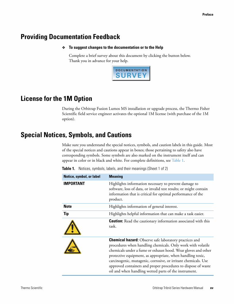
Providing Documentation Feedback To suggest changes to the documentation or to the Help
Complete a brief survey about this document by clicking the button below. Thank you in advance for your help.
License for the 1M OptionDuring the Orbitrap Fusion Lumos MS installation or upgrade process, the Thermo Fisher Scientific field service engineer activates the optional 1M license (with purchase of the 1M option).
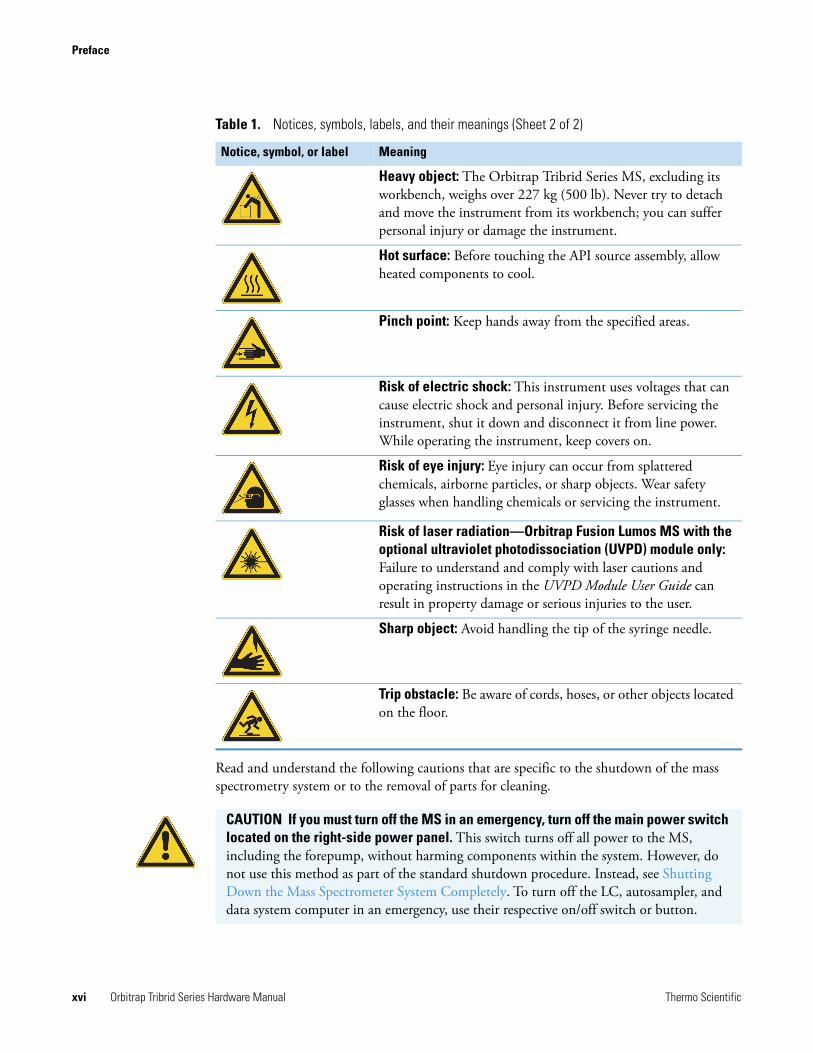
Special Notices, Symbols, and CautionsMake sure you understand the special notices, symbols, and caution labels in this guide. Most of the special notices and cautions appear in boxes; those pertaining to safety also have corresponding symbols. Some symbols are also marked on the instrument itself and can appear in color or in black and white. For complete definitions, see Table 1.
Table 1. Notices, symbols, labels, and their meanings (Sheet 1 of 2)
Notice, symbol, or label Meaning
IMPORTANT Highlights information necessary to prevent damage to software, loss of data, or invalid test results; or might contain information that is critical for optimal performance of the product.
Note Highlights information of general interest.
Tip Highlights helpful information that can make a task easier.
Caution: Read the cautionary information associated with this task.
Chemical hazard: Observe safe laboratory practices and procedures when handling chemicals. Only work with volatile chemicals under a fume or exhaust hood. Wear gloves and other protective equipment, as appropriate, when handling toxic, carcinogenic, mutagenic, corrosive, or irritant chemicals. Use approved containers and proper procedures to dispose of waste oil and when handling wetted parts of the instrument.
Preface
xvi Orbitrap Tribrid Series Hardware Manual Thermo Scientific
Read and understand the following cautions that are specific to the shutdown of the mass spectrometry system or to the removal of parts for cleaning.
Heavy object: The Orbitrap Tribrid Series MS, excluding its workbench, weighs over 227 kg (500 lb). Never try to detach and move the instrument from its workbench; you can suffer personal injury or damage the instrument.
Hot surface: Before touching the API source assembly, allow heated components to cool.
Pinch point: Keep hands away from the specified areas.
Risk of electric shock: This instrument uses voltages that can cause electric shock and personal injury. Before servicing the instrument, shut it down and disconnect it from line power. While operating the instrument, keep covers on.
Risk of eye injury: Eye injury can occur from splattered chemicals, airborne particles, or sharp objects. Wear safety glasses when handling chemicals or servicing the instrument.
Risk of laser radiation—Orbitrap Fusion Lumos MS with the optional ultraviolet photodissociation (UVPD) module only: Failure to understand and comply with laser cautions and operating instructions in the UVPD Module User Guide can result in property damage or serious injuries to the user.
Sharp object: Avoid handling the tip of the syringe needle.
Trip obstacle: Be aware of cords, hoses, or other objects located on the floor.
Table 1. Notices, symbols, labels, and their meanings (Sheet 2 of 2)
Notice, symbol, or label Meaning
CAUTION If you must turn off the MS in an emergency, turn off the main power switch located on the right-side power panel. This switch turns off all power to the MS, including the forepump, without harming components within the system. However, do not use this method as part of the standard shutdown procedure. Instead, see Shutting Down the Mass Spectrometer System Completely. To turn off the LC, autosampler, and data system computer in an emergency, use their respective on/off switch or button.
Preface
Thermo Scientific Orbitrap Tribrid Series Hardware Manual xvii
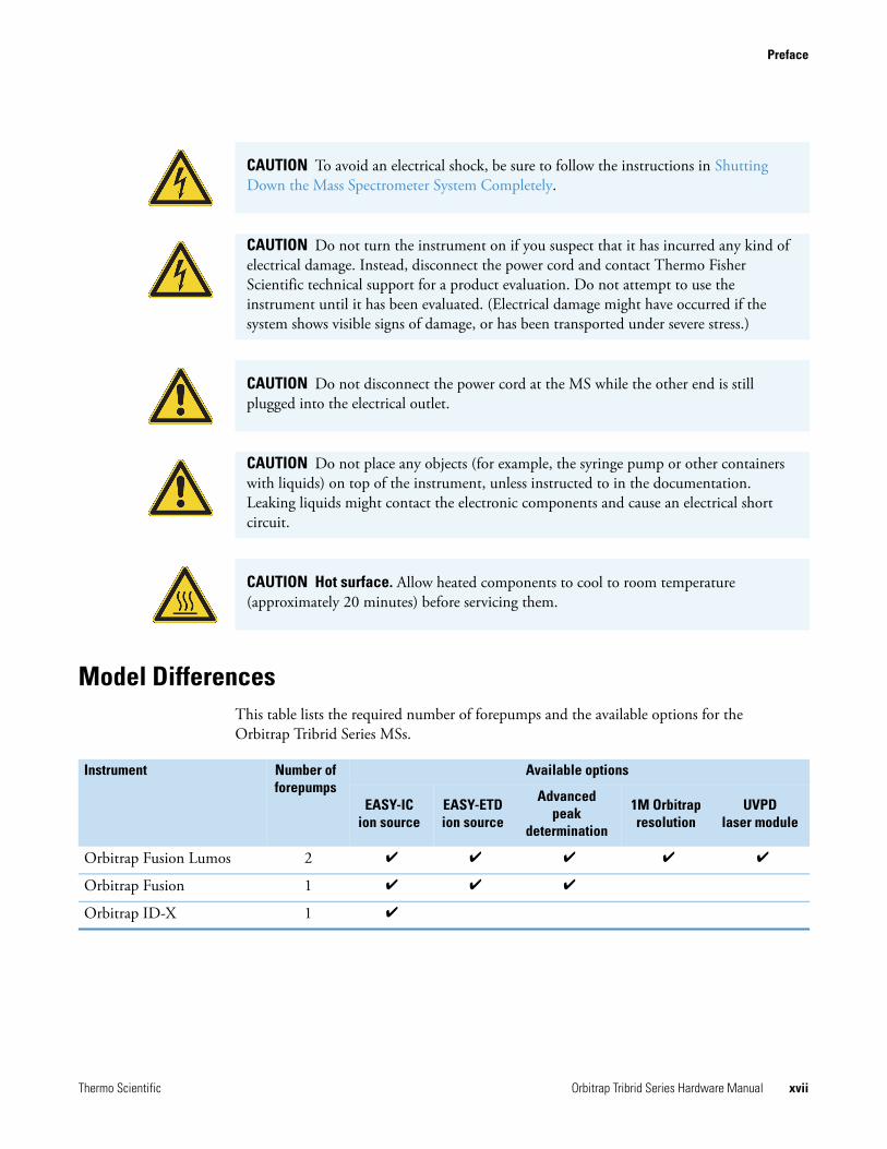
Model DifferencesThis table lists the required number of forepumps and the available options for the Orbitrap Tribrid Series MSs.
CAUTION To avoid an electrical shock, be sure to follow the instructions in Shutting Down the Mass Spectrometer System Completely.
CAUTION Do not turn the instrument on if you suspect that it has incurred any kind of electrical damage. Instead, disconnect the power cord and contact Thermo Fisher Scientific technical support for a product evaluation. Do not attempt to use the instrument until it has been evaluated. (Electrical damage might have occurred if the system shows visible signs of damage, or has been transported under severe stress.)
CAUTION Do not disconnect the power cord at the MS while the other end is still plugged into the electrical outlet.
CAUTION Do not place any objects (for example, the syringe pump or other containers with liquids) on top of the instrument, unless instructed to in the documentation. Leaking liquids might contact the electronic components and cause an electrical short circuit.
CAUTION Hot surface. Allow heated components to cool to room temperature (approximately 20 minutes) before servicing them.
Instrument Number offorepumps
Available options
EASY-ICion source
EASY-ETDion source
Advanced peak
determination
1M Orbitrapresolution
UVPDlaser module
Orbitrap Fusion Lumos 2
Orbitrap Fusion 1
Orbitrap ID-X 1
Preface
xviii Orbitrap Tribrid Series Hardware Manual Thermo Scientific
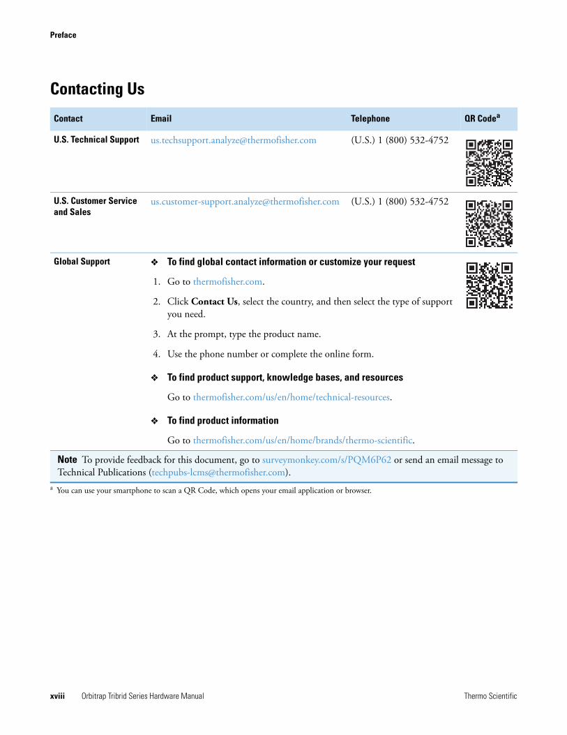
Contacting Us
Contact Email Telephone QR Codea
a You can use your smartphone to scan a QR Code, which opens your email application or browser.
U.S. Technical Support [email protected] (U.S.) 1 (800) 532-4752
U.S. Customer Service and Sales
[email protected] (U.S.) 1 (800) 532-4752
Global Support To find global contact information or customize your request
1. Go to thermofisher.com.
2. Click Contact Us, select the country, and then select the type of support you need.
3. At the prompt, type the product name.
4. Use the phone number or complete the online form.
To find product support, knowledge bases, and resources
Go to thermofisher.com/us/en/home/technical-resources.
To find product information
Go to thermofisher.com/us/en/home/brands/thermo-scientific.
Note To provide feedback for this document, go to surveymonkey.com/s/PQM6P62 or send an email message to Technical Publications ([email protected]).
Thermo Scientific Orbitrap Tribrid Series Hardware Manual 1
1
Introduction
The Orbitrap Tribrid Series MS is part of the Thermo Scientific family of MSs. The Orbitrap Tribrid Series system consists of the MS, a syringe pump, a divert/inject valve, and the Thermo Xcalibur data system.
Contents
• Orbitrap Tribrid Series Mass Spectrometers
• Overview of an LC/MS Analysis
• LC/MS Functional Block Diagram
• Electronic Assemblies
• Controls and Indicators
• Cooling Fans
Orbitrap Tribrid Series Mass SpectrometersSee these topics:
• Orbitrap Fusion MS
• Orbitrap Fusion Lumos MS
• Orbitrap ID-X MS
For a summary of the significant differences, see Model Differences.
For descriptions of the various hardware components, see Chapter 3, “Vacuum System,” Chapter 4, “Ion Transmission and Mass Analysis,” and Chapter 5, “Syringe Pump and Divert/Inject Valve.”
For an MS with the ETD option (see Model Differences), refer to the EASY-ETD and EASY-IC Ion Sources User Guide. For an Orbitrap Fusion Lumos MS with the UVPD option, refer to the UVPD Module User Guide.
Note The “Glossary” defines some of the terms used in this manual.
1 IntroductionOrbitrap Tribrid Series Mass Spectrometers
2 Orbitrap Tribrid Series Hardware Manual Thermo Scientific
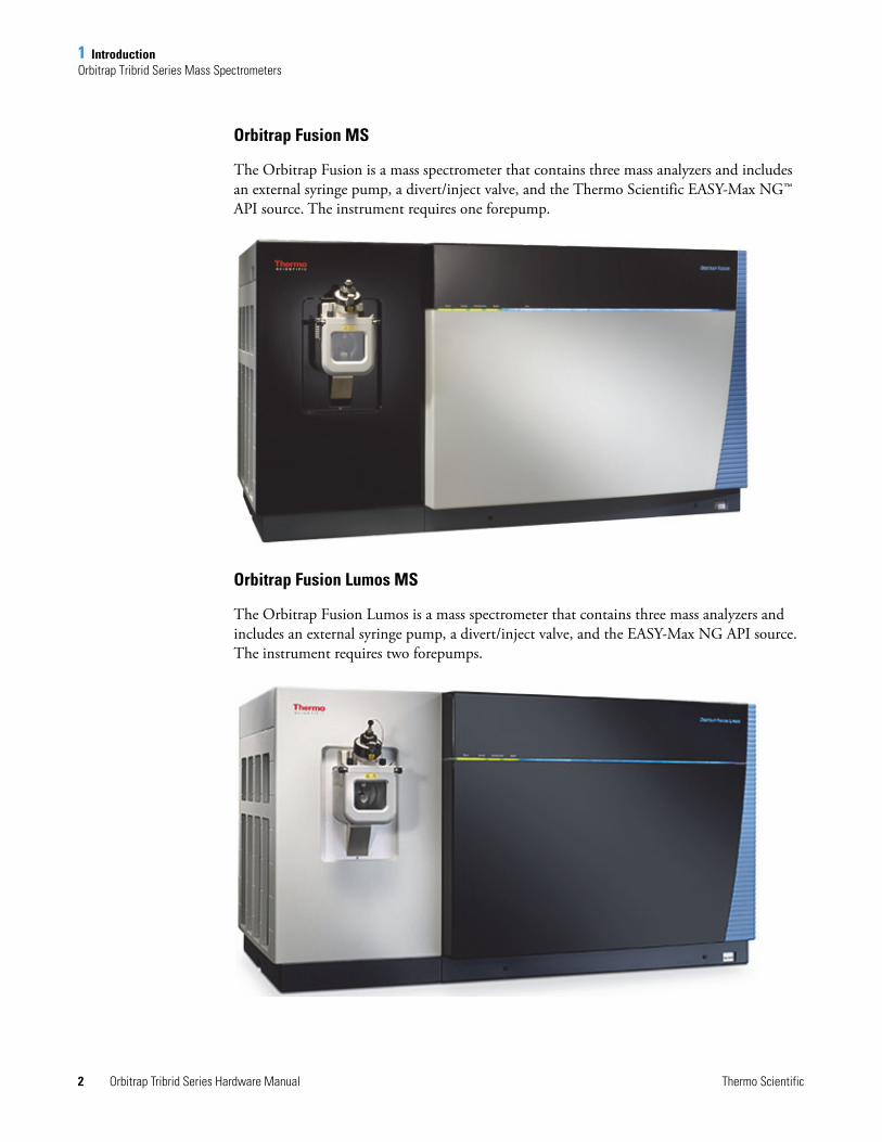
Orbitrap Fusion MS
The Orbitrap Fusion is a mass spectrometer that contains three mass analyzers and includes an external syringe pump, a divert/inject valve, and the Thermo Scientific EASY-Max NG™ API source. The instrument requires one forepump.
Orbitrap Fusion Lumos MS
The Orbitrap Fusion Lumos is a mass spectrometer that contains three mass analyzers and includes an external syringe pump, a divert/inject valve, and the EASY-Max NG API source. The instrument requires two forepumps.
1 IntroductionOverview of an LC/MS Analysis
Thermo Scientific Orbitrap Tribrid Series Hardware Manual 3
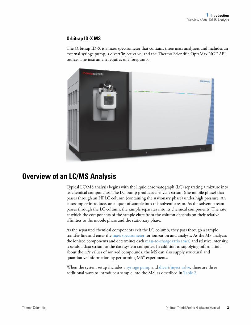
Orbitrap ID-X MS
The Orbitrap ID-X is a mass spectrometer that contains three mass analyzers and includes an external syringe pump, a divert/inject valve, and the Thermo Scientific OptaMax NG™ API source. The instrument requires one forepump.
Overview of an LC/MS AnalysisTypical LC/MS analysis begins with the liquid chromatograph (LC) separating a mixture into its chemical components. The LC pump produces a solvent stream (the mobile phase) that passes through an HPLC column (containing the stationary phase) under high pressure. An autosampler introduces an aliquot of sample into this solvent stream. As the solvent stream passes through the LC column, the sample separates into its chemical components. The rate at which the components of the sample elute from the column depends on their relative affinities to the mobile phase and the stationary phase.
As the separated chemical components exit the LC column, they pass through a sample transfer line and enter the mass spectrometer for ionization and analysis. As the MS analyzes the ionized components and determines each mass-to-charge ratio (m/z) and relative intensity, it sends a data stream to the data system computer. In addition to supplying information about the m/z values of ionized compounds, the MS can also supply structural and quantitative information by performing MSn experiments.
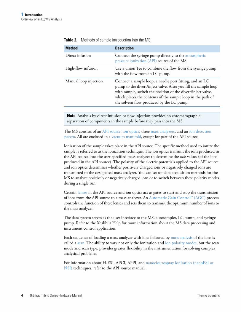
When the system setup includes a syringe pump and divert/inject valve, there are three additional ways to introduce a sample into the MS, as described in Table 2.
1 IntroductionOverview of an LC/MS Analysis
4 Orbitrap Tribrid Series Hardware Manual Thermo Scientific
The MS consists of an API source, ion optics, three mass analyzers, and an ion detection system. All are enclosed in a vacuum manifold, except for part of the API source.
Ionization of the sample takes place in the API source. The specific method used to ionize the sample is referred to as the ionization technique. The ion optics transmit the ions produced in the API source into the user-specified mass analyzer to determine the m/z values (of the ions produced in the API source). The polarity of the electric potentials applied to the API source and ion optics determines whether positively charged ions or negatively charged ions are transmitted to the designated mass analyzer. You can set up data acquisition methods for the MS to analyze positively or negatively charged ions or to switch between these polarity modes during a single run.
Certain lenses in the API source and ion optics act as gates to start and stop the transmission of ions from the API source to a mass analyzer. An Automatic Gain Control™ (AGC) process controls the function of these lenses and sets them to transmit the optimum number of ions to the mass analyzer.
The data system serves as the user interface to the MS, autosampler, LC pump, and syringe pump. Refer to the Xcalibur Help for more information about the MS data processing and instrument control application.
Each sequence of loading a mass analyzer with ions followed by mass analysis of the ions is called a scan. The ability to vary not only the ionization and ion polarity modes, but the scan mode and scan type, provides greater flexibility in the instrumentation for solving complex analytical problems.
For information about H-ESI, APCI, APPI, and nanoelectrospray ionization (nanoESI or NSI) techniques, refer to the API source manual.
Table 2. Methods of sample introduction into the MS
Method Description
Direct infusion Connect the syringe pump directly to the atmospheric pressure ionization (API) source of the MS.
High-flow infusion Use a union Tee to combine the flow from the syringe pump with the flow from an LC pump.
Manual loop injection Connect a sample loop, a needle port fitting, and an LC pump to the divert/inject valve. After you fill the sample loop with sample, switch the position of the divert/inject valve, which places the contents of the sample loop in the path of the solvent flow produced by the LC pump.
Note Analysis by direct infusion or flow injection provides no chromatographic separation of components in the sample before they pass into the MS.
1 IntroductionLC/MS Functional Block Diagram
Thermo Scientific Orbitrap Tribrid Series Hardware Manual 5
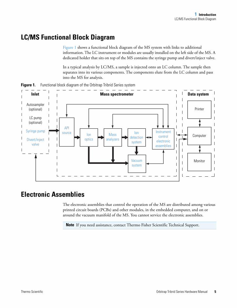
LC/MS Functional Block DiagramFigure 1 shows a functional block diagram of the MS system with links to additional information. The LC instrument or modules are usually installed on the left side of the MS. A dedicated holder that sits on top of the MS contains the syringe pump and divert/inject valve.
In a typical analysis by LC/MS, a sample is injected onto an LC column. The sample then separates into its various components. The components elute from the LC column and pass into the MS for analysis.
Figure 1. Functional block diagram of the Orbitrap Tribrid Series system
Electronic AssembliesThe electronic assemblies that control the operation of the MS are distributed among various printed circuit boards (PCBs) and other modules, in the embedded computer, and on or around the vacuum manifold of the MS. You cannot service the electronic assemblies.
Ion optics
Mass analyzers
Ion detection system
Instrument control
electronic assemblies
Vacuum system
Printer
Computer
Monitor
Mass spectrometer Data systemInlet
Autosampler (optional)
LC pump (optional)
Syringe pump
Divert/injectvalve
API source
Note If you need assistance, contact Thermo Fisher Scientific Technical Support.
1 IntroductionControls and Indicators
6 Orbitrap Tribrid Series Hardware Manual Thermo Scientific
Controls and IndicatorsSee these topics:
• LEDs
• Power Entry Module
• Communications Panel
LEDs
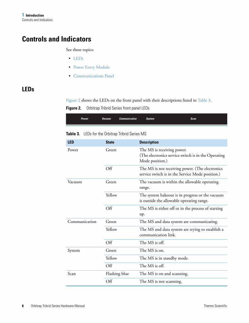
Figure 2 shows the LEDs on the front panel with their descriptions listed in Table 3.
Figure 2. Orbitrap Tribrid Series front panel LEDs
Table 3. LEDs for the Orbitrap Tribrid Series MS
LED State Description
Power Green The MS is receiving power. (The electronics service switch is in the Operating Mode position.)
Off The MS is not receiving power. (The electronics service switch is in the Service Mode position.)
Vacuum Green The vacuum is within the allowable operating range.
Yellow The system bakeout is in progress or the vacuum is outside the allowable operating range.
Off The MS is either off or in the process of starting up.
Communication Green The MS and data system are communicating.
Yellow The MS and data system are trying to establish a communication link.
Off The MS is off.
System Green The MS is on.
Yellow The MS is in standby mode.
Off The MS is off.
Scan Flashing blue The MS is on and scanning.
Off The MS is not scanning.

1 IntroductionControls and Indicators
Thermo Scientific Orbitrap Tribrid Series Hardware Manual 7
Power Entry Module
The MS receives line power at 230 Vac ±10%, 15 A, 50/60 Hz through the right-side power entry module (Figure 3).
Figure 3. Power entry module
Main Power Switch
In the Off position, the Main Power (circuit breaker) switch removes all power to the MS, including the external forepump or forepumps. In the On position, the MS receives power. In the standard operational mode, the switch stays in the On position.
Electronics Service Switch
The electronics service switch is a circuit breaker. In the Service Mode (down) position, the switch removes power to all components of the MS except for the fans and vacuum system. This setting allows you to service nonvacuum system components with the vacuum system still operating. In the Operating Mode (up) position, all components of the MS have power.
SV65 Pump Enable Connector
The MS turns the forepump or forepumps on and off by using the relay control cable that connects to the SV65 Pump Enable connector.
Power In receptacle (230 Vac)
Main Power switch
Electronics service switch
SV65 Pump Enable connector (forepump on/off control)
AC Output receptacle (reserved for future use)
CAUTION In an emergency do not use the electronics service switch to shut off power to the MS. Instead, place the main power circuit breaker switch (labeled Main Power) in the Off (down) position and disconnect the power cord from the electrical outlet.
1 IntroductionControls and Indicators
8 Orbitrap Tribrid Series Hardware Manual Thermo Scientific
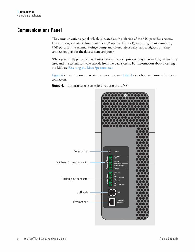
Communications Panel
The communications panel, which is located on the left side of the MS, provides a system Reset button, a contact closure interface (Peripheral Control), an analog input connector, USB ports for the external syringe pump and divert/inject valve, and a Gigabit Ethernet connection port for the data system computer.
When you briefly press the reset button, the embedded processing system and digital circuitry reset and the system software reloads from the data system. For information about resetting the MS, see Resetting the Mass Spectrometer.
Figure 4 shows the communication connectors, and Table 4 describes the pin-outs for these connectors.
Figure 4. Communication connectors (left side of the MS)
Peripheral Control connector
Analog Input connector
USB ports
Ethernet port
Reset button
1 IntroductionControls and Indicators
Thermo Scientific Orbitrap Tribrid Series Hardware Manual 9
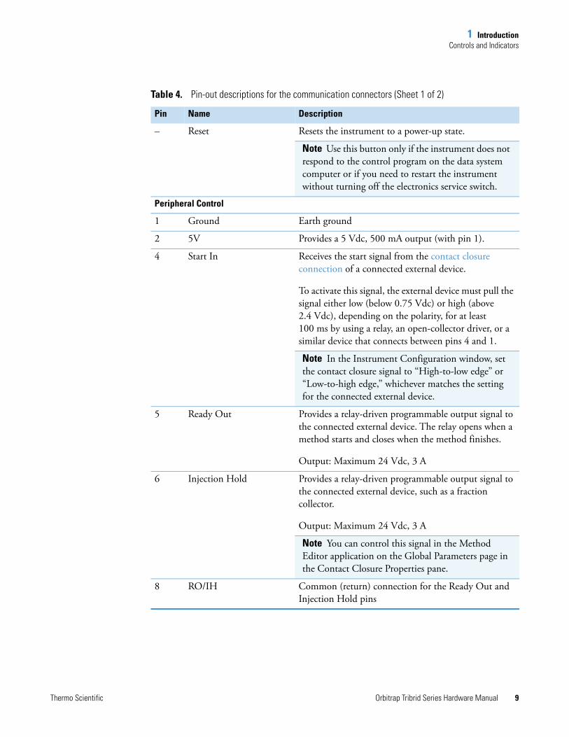
Table 4. Pin-out descriptions for the communication connectors (Sheet 1 of 2)
Pin Name Description
– Reset Resets the instrument to a power-up state.
Note Use this button only if the instrument does not respond to the control program on the data system computer or if you need to restart the instrument without turning off the electronics service switch.
Peripheral Control
1 Ground Earth ground
2 5V Provides a 5 Vdc, 500 mA output (with pin 1).
4 Start In Receives the start signal from the contact closure connection of a connected external device.
To activate this signal, the external device must pull the signal either low (below 0.75 Vdc) or high (above 2.4 Vdc), depending on the polarity, for at least 100 ms by using a relay, an open-collector driver, or a similar device that connects between pins 4 and 1.
Note In the Instrument Configuration window, set the contact closure signal to “High-to-low edge” or “Low-to-high edge,” whichever matches the setting for the connected external device.
5 Ready Out Provides a relay-driven programmable output signal to the connected external device. The relay opens when a method starts and closes when the method finishes.
Output: Maximum 24 Vdc, 3 A
6 Injection Hold Provides a relay-driven programmable output signal to the connected external device, such as a fraction collector.
Output: Maximum 24 Vdc, 3 A
Note You can control this signal in the Method Editor application on the Global Parameters page in the Contact Closure Properties pane.
8 RO/IH Common (return) connection for the Ready Out and Injection Hold pins
1 IntroductionCooling Fans
10 Orbitrap Tribrid Series Hardware Manual Thermo Scientific
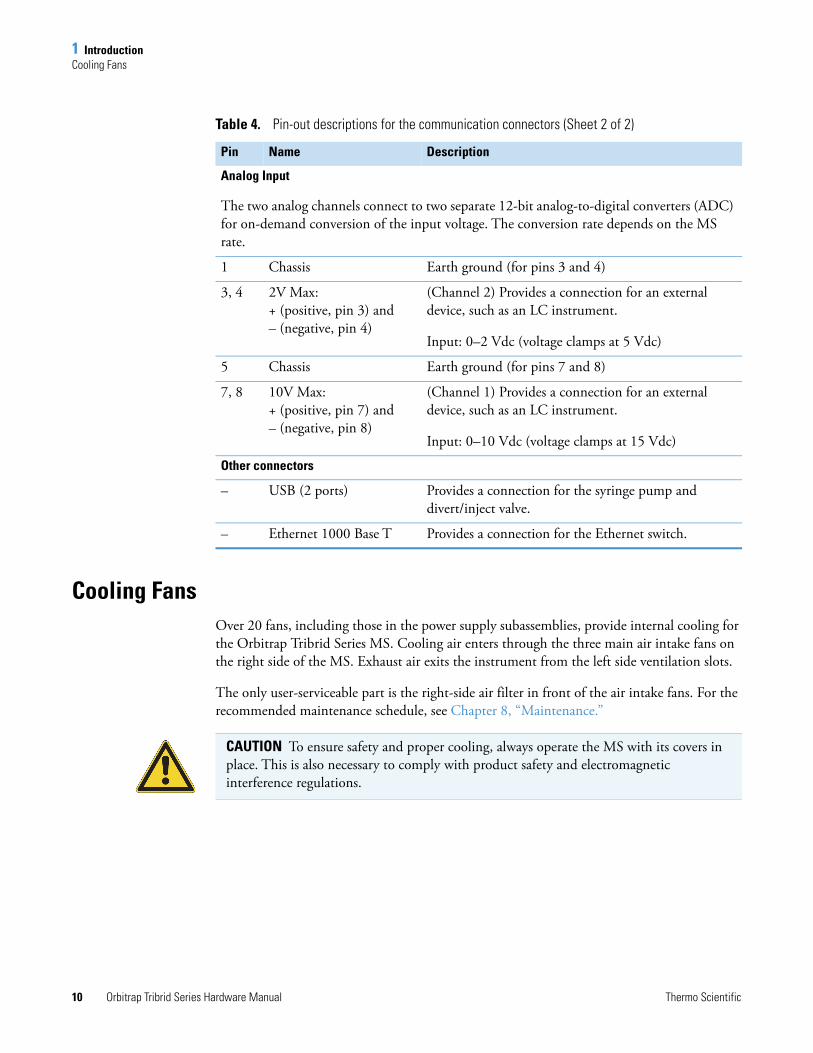
Cooling FansOver 20 fans, including those in the power supply subassemblies, provide internal cooling for the Orbitrap Tribrid Series MS. Cooling air enters through the three main air intake fans on the right side of the MS. Exhaust air exits the instrument from the left side ventilation slots.
The only user-serviceable part is the right-side air filter in front of the air intake fans. For the recommended maintenance schedule, see Chapter 8, “Maintenance.”
Analog Input
The two analog channels connect to two separate 12-bit analog-to-digital converters (ADC) for on-demand conversion of the input voltage. The conversion rate depends on the MS rate.
1 Chassis Earth ground (for pins 3 and 4)
3, 4 2V Max: + (positive, pin 3) and – (negative, pin 4)
(Channel 2) Provides a connection for an external device, such as an LC instrument.
Input: 0–2 Vdc (voltage clamps at 5 Vdc)
5 Chassis Earth ground (for pins 7 and 8)
7, 8 10V Max: + (positive, pin 7) and – (negative, pin 8)
(Channel 1) Provides a connection for an external device, such as an LC instrument.
Input: 0–10 Vdc (voltage clamps at 15 Vdc)
Other connectors
– USB (2 ports) Provides a connection for the syringe pump and divert/inject valve.
– Ethernet 1000 Base T Provides a connection for the Ethernet switch.
Table 4. Pin-out descriptions for the communication connectors (Sheet 2 of 2)
Pin Name Description
CAUTION To ensure safety and proper cooling, always operate the MS with its covers in place. This is also necessary to comply with product safety and electromagnetic interference regulations.
Thermo Scientific Orbitrap Tribrid Series Hardware Manual 11
2
Scan Parameters
This chapter describes some of the scan parameter settings that you set in the Orbitrap Tribrid Series Tune application.
Contents
• Scan Types
• Scan Rates for the Ion Trap Detector
• Scan Mass-To-Charge Ratio Ranges
• Resolutions for the Orbitrap Detector
• Data Types
• Ion Polarity Modes
Scan TypesSee these topics:
• MS Scan
• MS2 Scan and MSn Scan
• SIM Scan
MS Scan
The full-scan MS (or MS1) scan type corresponds to a single stage of mass analysis—that is, a scan power of n = 1.
With the single-stage full scan, the ions formed in the API source are stored in the ion-routing multipole (IRM). The MS then transfers these ions to either the Orbitrap or linear ion trap (LIT) to produce a full mass spectrum of the observable ions in the specified mass range at a specific time point in the analysis.
2 Scan ParametersScan Rates for the Ion Trap Detector
12 Orbitrap Tribrid Series Hardware Manual Thermo Scientific
Single-stage full-scan analysis is a useful tool for qualitative and quantitative analysis. Use single-stage full-scan experiments to determine the molecular weight and intensity of compounds present in the mass spectrum.
MS2 Scan and MSn Scan
An MS2 Scan selects the MS/MS mass analysis. An MSn Scan typically involves 2 to 10 stages of mass analysis (scan power of n = 2 to n = 10). Each stage of mass analysis where n > 1 includes an ion selection step. As you raise the scan power, you can obtain more structural information that can be useful in structure elucidation of compounds of interest. The Orbitrap Tribrid Series MS has several advanced features that make its MSn capabilities extremely powerful.
In an MS/MS scan, precursor ions fragment into product ions. The MS/MS scan type experiment can use a full-scan or a defined scan range.
• First stage of mass analysis—You can set either the Quadrupole or the Ion Trap to select the ions for MS/MS analysis. The MS then transfers the selected ions to the IRM for HCD or to the linear ion trap (LIT) for CID, ETD (for MSs with the ETD option1), or UVPD (for the Orbitrap Fusion Lumos MS with the UVPD option).
• Second stage of mass analysis—The MS transfers the product ions to either the Orbitrap or the LIT for detection.
In the nth stage of mass analysis, subsequent stages of product ion selection occur in the LIT.
SIM Scan
The selected ion monitoring (SIM) scan type is a single-stage (scan power of n = 1) technique that monitors a particular ion or set of ions. In a SIM scan, the MS selects ions in the defined m/z range, and ejects all other ions by using either the quadrupole or the LIT analyzer. The Orbitrap or the LIT then detects the selected ions to produce a SIM mass spectrum.
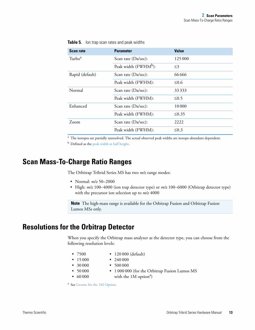
Scan Rates for the Ion Trap DetectorWith the Orbitrap Tribrid Series MS, you can use five scan rates: Turbo, Rapid, Normal, Enhanced, and Zoom. For information about these scan rates, refer to the Tune Help.
Table 5 lists the scan rates and their peak widths (resolutions) for the Orbitrap Tribrid Series MS. For additional information about the scan rates, refer to the Method Editor Help.
1 See Model Differences.
2 Scan ParametersScan Mass-To-Charge Ratio Ranges
Thermo Scientific Orbitrap Tribrid Series Hardware Manual 13
Scan Mass-To-Charge Ratio RangesThe Orbitrap Tribrid Series MS has two m/z range modes:
• Normal: m/z 50–2000 • High: m/z 100–4000 (ion trap detector type) or m/z 100–6000 (Orbitrap detector type)
with the precursor ion selection up to m/z 4000
Resolutions for the Orbitrap DetectorWhen you specify the Orbitrap mass analyzer as the detector type, you can choose from the following resolution levels:
Table 5. Ion trap scan rates and peak widths
Scan rate Parameter Value
Turboa
a The isotopes are partially unresolved. The actual observed peak widths are isotope-abundant dependent.
Scan rate (Da/sec): 125 000
Peak width (FWHMb):
b Defined as the peak width at half height.
3
Rapid (default) Scan rate (Da/sec): 66 666
Peak width (FWHM): 0.6
Normal Scan rate (Da/sec): 33 333
Peak width (FWHM): 0.5
Enhanced Scan rate (Da/sec): 10 000
Peak width (FWHM): 0.35
Zoom Scan rate (Da/sec): 2222
Peak width (FWHM): 0.3
Note The high-mass range is available for the Orbitrap Fusion and Orbitrap Fusion Lumos MSs only.
• 7500• 15 000• 30 000• 50 000• 60 000
• 120 000 (default)• 240 000• 500 000• 1 000 000 (for the Orbitrap Fusion Lumos MS
with the 1M optiona)a See License for the 1M Option.
2 Scan ParametersData Types
14 Orbitrap Tribrid Series Hardware Manual Thermo Scientific
Data TypesYou can acquire and display mass spectral data (intensity versus m/z) in one of two data types:
• Profile data—With profile data, you can see the inherent shape of the peaks in the mass spectrum. The mass spectrum divides each atomic mass unit into several sampling intervals. The intensity of the ion current is determined at each sampling interval. The intensity at each sampling interval is displayed with the intensities connected by a continuous line.
• Centroid data —With centroid data, you can see the mass spectrum as a bar graph. This scan data type sums the intensities of each set of sampling intervals. This sum is displayed versus the integral center of mass of the many sampling intervals. Centroid data requires about one-tenth the computer disk space of what is required for profile data.
Ion Polarity ModesThe Orbitrap Tribrid Series MS can operate in either positive or negative ion polarity mode. The MS controls whether positive ions or negative ions are transmitted to the mass analyzer for mass analysis by changing the polarity of the voltage potentials applied to the API source, ion optics, and ion detection system. The ion optics are located between the API source and the mass analyzer. For a schematic of the ion transmission path, see Figure 13.
Thermo Scientific Orbitrap Tribrid Series Hardware Manual 15
3
Vacuum System
This chapter describes the principal components of the vacuum system for the Orbitrap Tribrid Series MS.
Contents
• Vacuum System Functional Block Diagram
• Schematic of the Internal Gas Supply Lines
• Inlet Gases Hardware
• Vacuum Manifold
• Vacuum Gauges
• Vacuum Pumps
• Atmospheric Pressure Ionization Source
• API Source Interface
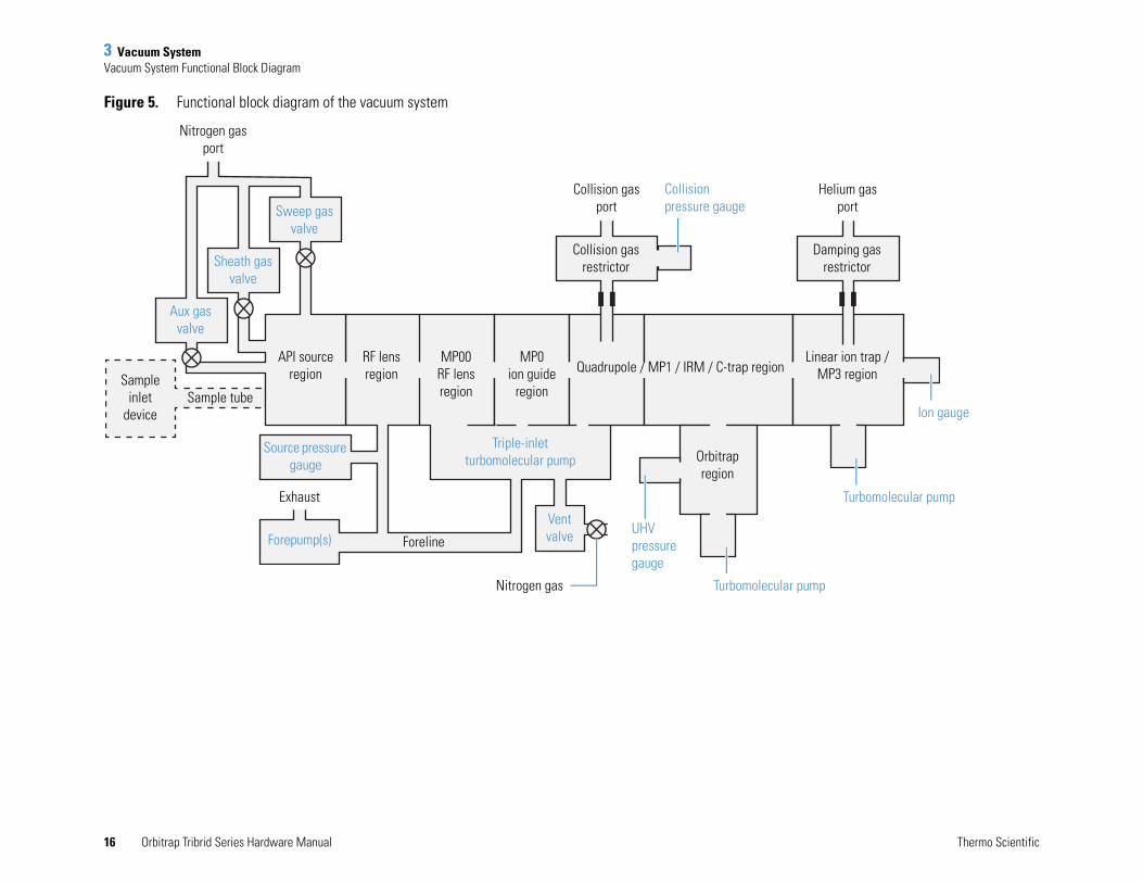
Vacuum System Functional Block DiagramThe vacuum system evacuates the region around the API source interface, ion optics, mass analyzers, and ion detection system. Figure 5 shows a functional block diagram of the vacuum system with links to additional information.
16 Orbitrap Tribrid Series Hardware Manual Thermo Scientific
3 Vacuum SystemVacuum System Functional Block Diagram
Figure 5. Functional block diagram of the vacuum system
Nitrogen gas port
Sweep gas valve
Sheath gas valve
Aux gas valve
Sample inlet
deviceSample tube
API source region
RF lens region
MP00 RF lens region
MP0 ion guide
region
Quadrupole / MP1 / IRM / C-trap regionLinear ion trap /
MP3 region
Damping gas restrictor
Helium gas port
Collision gas restrictor
Collision gas port
Orbitrap region
UHV pressure gauge
Vent valve
Triple-inlet turbomolecular pump
ForelineForepump(s)
Exhaust
Source pressure gauge
Collision pressure gauge
Turbomolecular pump
Turbomolecular pump
Ion gauge
Nitrogen gas
3 Vacuum SystemSchematic of the Internal Gas Supply Lines
Thermo Scientific Orbitrap Tribrid Series Hardware Manual 17
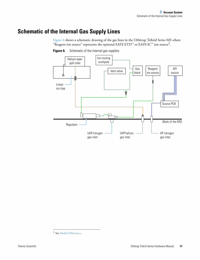
Schematic of the Internal Gas Supply LinesFigure 6 shows a schematic drawing of the gas lines in the Orbitrap Tribrid Series MS where “Reagent ion source” represents the optional EASY-ETD™ or EASY-IC™ ion source2.
Figure 6. Schematic of the internal gas supplies
2 See Model Differences.
Helium open split inlet
Gas block
Reagent ion source
API source
Ion-routing multipole
Vent valve
Source PCB
Regulator
UHP nitrogen gas inlet
UHP helium gas inlet
HP nitrogen gas inlet
Linear ion trap
(Back of the MS)

3 Vacuum SystemInlet Gases Hardware
18 Orbitrap Tribrid Series Hardware Manual Thermo Scientific
Inlet Gases HardwareThe inlet gas hardware controls the flow of the helium damping gas; the nitrogen sheath gas, auxiliary gas, sweep gas, and collision gas; and the nitrogen venting gas into the MS. Figure 7 shows the gas inlets on the back of the MS.
• Helium Regulator
• Nitrogen Gas Valves
• Vent Valve
Figure 7. Gas inlet ports (back of the MS)
UHP nitrogen gas inlet
HP nitrogen gas inlet
UHP helium gas inlet
Orbitrap Fusion and Orbitrap ID-X MSs
Orbitrap Fusion Lumos MS
UHP nitrogen gas inlet
HP nitrogen gas inlet
UHP helium gas inlet
3 Vacuum SystemInlet Gases Hardware
Thermo Scientific Orbitrap Tribrid Series Hardware Manual 19
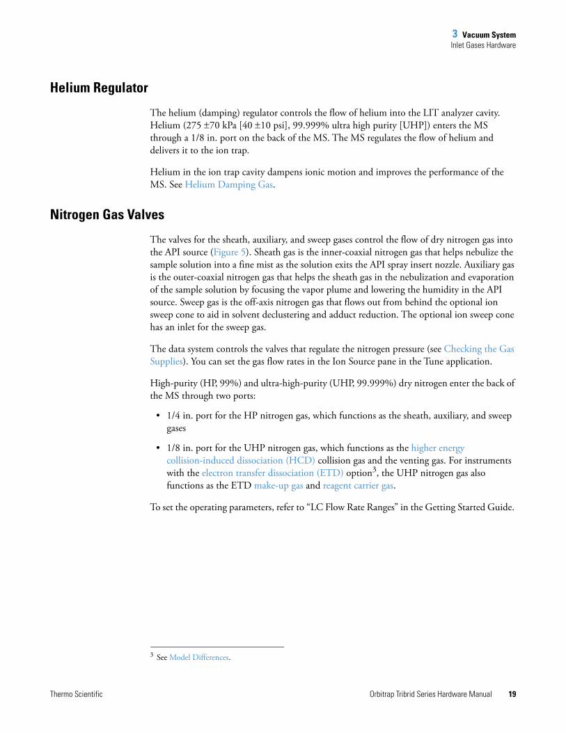
Helium Regulator
The helium (damping) regulator controls the flow of helium into the LIT analyzer cavity. Helium (275 70 kPa [40 10 psi], 99.999% ultra high purity [UHP]) enters the MS through a 1/8 in. port on the back of the MS. The MS regulates the flow of helium and delivers it to the ion trap.
Helium in the ion trap cavity dampens ionic motion and improves the performance of the MS. See Helium Damping Gas.
Nitrogen Gas Valves
The valves for the sheath, auxiliary, and sweep gases control the flow of dry nitrogen gas into the API source (Figure 5). Sheath gas is the inner-coaxial nitrogen gas that helps nebulize the sample solution into a fine mist as the solution exits the API spray insert nozzle. Auxiliary gas is the outer-coaxial nitrogen gas that helps the sheath gas in the nebulization and evaporation of the sample solution by focusing the vapor plume and lowering the humidity in the API source. Sweep gas is the off-axis nitrogen gas that flows out from behind the optional ion sweep cone to aid in solvent declustering and adduct reduction. The optional ion sweep cone has an inlet for the sweep gas.
The data system controls the valves that regulate the nitrogen pressure (see Checking the Gas Supplies). You can set the gas flow rates in the Ion Source pane in the Tune application.
High-purity (HP, 99%) and ultra-high-purity (UHP, 99.999%) dry nitrogen enter the back of the MS through two ports:
• 1/4 in. port for the HP nitrogen gas, which functions as the sheath, auxiliary, and sweep gases
• 1/8 in. port for the UHP nitrogen gas, which functions as the higher energy collision-induced dissociation (HCD) collision gas and the venting gas. For instruments with the electron transfer dissociation (ETD) option3, the UHP nitrogen gas also functions as the ETD make-up gas and reagent carrier gas.
To set the operating parameters, refer to “LC Flow Rate Ranges” in the Getting Started Guide.
3 See Model Differences.
3 Vacuum SystemVacuum Manifold
20 Orbitrap Tribrid Series Hardware Manual Thermo Scientific
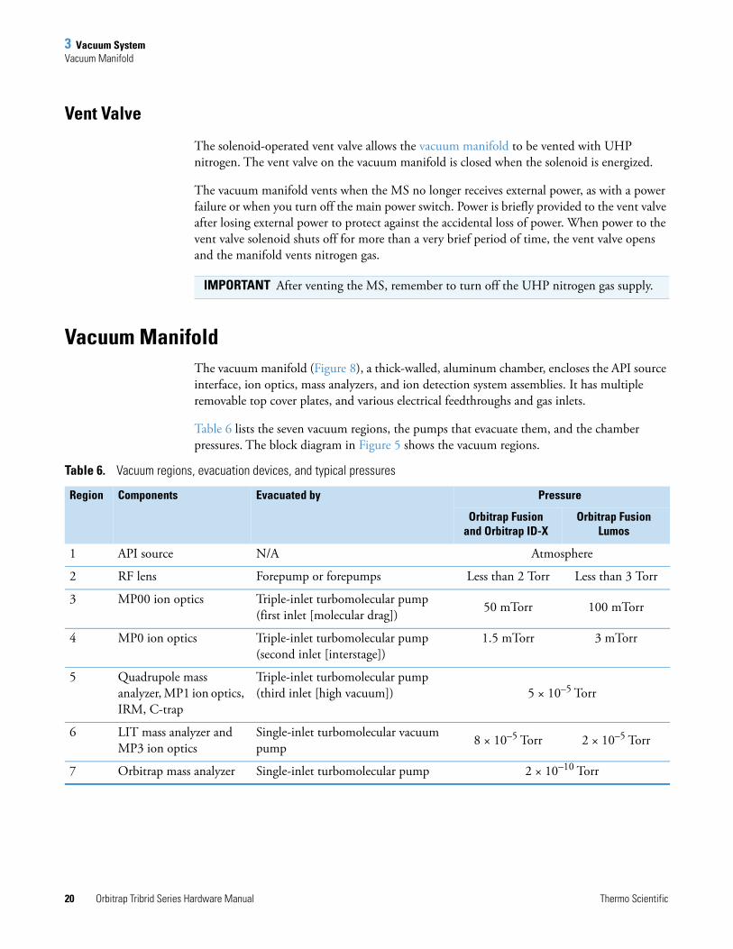
Vent Valve
The solenoid-operated vent valve allows the vacuum manifold to be vented with UHP nitrogen. The vent valve on the vacuum manifold is closed when the solenoid is energized.
The vacuum manifold vents when the MS no longer receives external power, as with a power failure or when you turn off the main power switch. Power is briefly provided to the vent valve after losing external power to protect against the accidental loss of power. When power to the vent valve solenoid shuts off for more than a very brief period of time, the vent valve opens and the manifold vents nitrogen gas.
Vacuum ManifoldThe vacuum manifold (Figure 8), a thick-walled, aluminum chamber, encloses the API source interface, ion optics, mass analyzers, and ion detection system assemblies. It has multiple removable top cover plates, and various electrical feedthroughs and gas inlets.
Table 6 lists the seven vacuum regions, the pumps that evacuate them, and the chamber pressures. The block diagram in Figure 5 shows the vacuum regions.
IMPORTANT After venting the MS, remember to turn off the UHP nitrogen gas supply.
Table 6. Vacuum regions, evacuation devices, and typical pressures
Region Components Evacuated by Pressure
Orbitrap Fusion and Orbitrap ID-X
Orbitrap Fusion Lumos
1 API source N/A Atmosphere
2 RF lens Forepump or forepumps Less than 2 Torr Less than 3 Torr
3 MP00 ion optics Triple-inlet turbomolecular pump (first inlet [molecular drag]) 50 mTorr 100 mTorr
4 MP0 ion optics Triple-inlet turbomolecular pump (second inlet [interstage])
1.5 mTorr 3 mTorr
5 Quadrupole mass analyzer, MP1 ion optics, IRM, C-trap
Triple-inlet turbomolecular pump (third inlet [high vacuum]) 5 × 10⁻⁵ Torr
6 LIT mass analyzer and MP3 ion optics
Single-inlet turbomolecular vacuum pump 8 × 10⁻⁵ Torr 2 × 10⁻⁵ Torr
7 Orbitrap mass analyzer Single-inlet turbomolecular pump 2 × 10⁻¹⁰ Torr
3 Vacuum SystemVacuum Gauges
Thermo Scientific Orbitrap Tribrid Series Hardware Manual 21
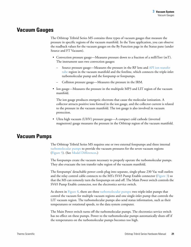
Vacuum GaugesThe Orbitrap Tribrid Series MS contains three types of vacuum gauges that measure the pressure in specific regions of the vacuum manifold. In the Tune application, you can observe the readback values for the vacuum gauges on the By Function page in the Status pane (under Source and FT Vacuum).
• Convection pressure gauge—Measures pressure down to a fraction of a milliTorr (mT). The instrument uses two convection gauges:
– Source pressure gauge—Measures the pressure in the RF lens and API ion transfer tube region in the vacuum manifold and the foreline, which connects the triple-inlet turbomolecular pump and the forepump or forepumps.
– Collision pressure gauge—Measures the pressure in the IRM.
• Ion gauge—Measures the pressure in the multipole MP3 and LIT region of the vacuum manifold.
The ion gauge produces energetic electrons that cause the molecular ionization. A collector attracts positive ions formed in the ion gauge, and the collector current is related to the pressure in the vacuum manifold. The ion gauge is also involved in vacuum protection.
• Ultra high vacuum (UHV) pressure gauge—A compact cold cathode (inverted magnetron) gauge measures the pressure in the Orbitrap region of the vacuum manifold.
Vacuum PumpsThe Orbitrap Tribrid Series MS requires one or two external forepumps and three internal turbomolecular pumps to provide the vacuum pressures for the seven vacuum regions (Figure 5). (See Model Differences.)
The forepumps create the vacuum necessary to properly operate the turbomolecular pumps. They also evacuate the ion transfer tube region of the vacuum manifold.
The forepumps’ detachable power cords plug into separate, single-phase 230 Vac wall outlets and the relay control cable connects to the MS’s SV65 Pump Enable connector (Figure 3) so that the MS can remotely turn the forepumps on and off. The Main Power switch controls the SV65 Pump Enable connector, not the electronics service switch.
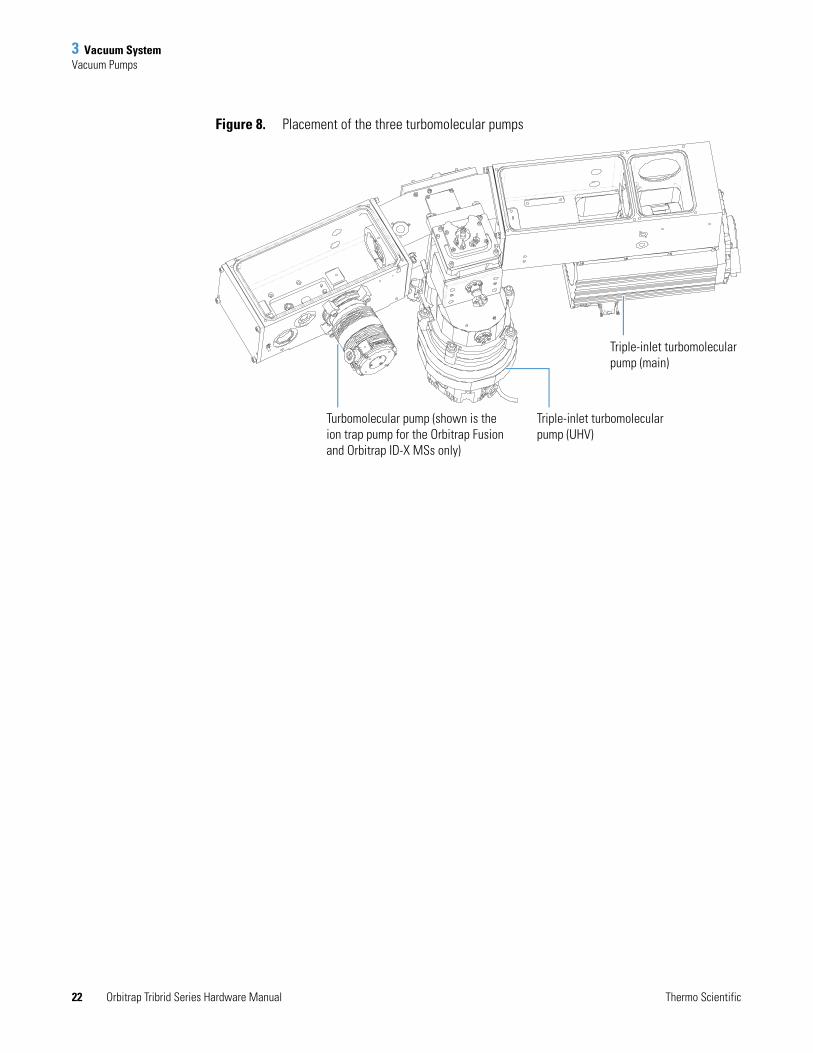
As shown in Figure 8, there are three turbomolecular pumps: two triple-inlet pumps that control the vacuum for multiple vacuum regions and one single-inlet pump that controls the LIT vacuum region. The turbomolecular pumps also send status information, such as their temperatures or rotational speeds, to the data system computer.
The Main Power switch turns off the turbomolecular pumps. The electronics service switch has no effect on these pumps. Power to the turbomolecular pumps automatically shuts off if the temperatures on the turbomolecular pumps becomes too high.
3 Vacuum SystemVacuum Pumps
22 Orbitrap Tribrid Series Hardware Manual Thermo Scientific
Figure 8. Placement of the three turbomolecular pumps
Triple-inlet turbomolecular pump (main)
Triple-inlet turbomolecular pump (UHV)
Turbomolecular pump (shown is the ion trap pump for the Orbitrap Fusion and Orbitrap ID-X MSs only)

3 Vacuum SystemAtmospheric Pressure Ionization Source
Thermo Scientific Orbitrap Tribrid Series Hardware Manual 23
Atmospheric Pressure Ionization SourceThe atmospheric pressure ionization (API) source forms gas phase sample ions from sample molecules that are contained in solution. The API source also serves as the interface between the LC and the MS. You can configure the API source, which is provided with the MS, for the following ionization techniques: heated-electrospray (H-ESI), atmospheric pressure chemical ionization (APCI), and atmospheric pressure photoionization (APPI).
The Orbitrap Tribrid Series MS has a front, built-in drain that routes the solvent waste from the API source to the solvent waste container connected to the back drain/waste port. For information about the solvent waste connection, refer to the Getting Connected Guide.
For information about the API source, refer to the API source manual and “Setting Up the Ion Source” in the Getting Started Guide.
Figure 9. Thermo Scientific API source (H-ESI mode)
ESI spray insert
API source housing
Locking lever (locked position)
Sample inlet
3 Vacuum SystemAPI Source Interface
24 Orbitrap Tribrid Series Hardware Manual Thermo Scientific
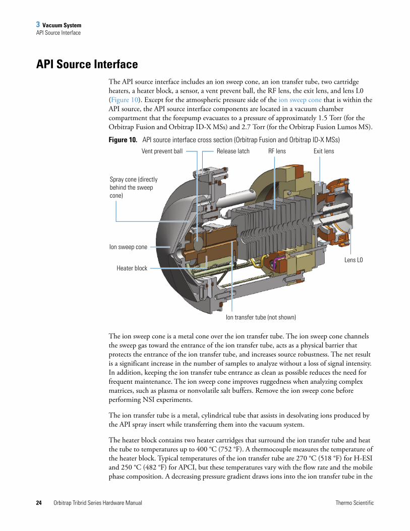
API Source InterfaceThe API source interface includes an ion sweep cone, an ion transfer tube, two cartridge heaters, a heater block, a sensor, a vent prevent ball, the RF lens, the exit lens, and lens L0 (Figure 10). Except for the atmospheric pressure side of the ion sweep cone that is within the API source, the API source interface components are located in a vacuum chamber compartment that the forepump evacuates to a pressure of approximately 1.5 Torr (for the Orbitrap Fusion and Orbitrap ID-X MSs) and 2.7 Torr (for the Orbitrap Fusion Lumos MS).
Figure 10. API source interface cross section (Orbitrap Fusion and Orbitrap ID-X MSs)
The ion sweep cone is a metal cone over the ion transfer tube. The ion sweep cone channels the sweep gas toward the entrance of the ion transfer tube, acts as a physical barrier that protects the entrance of the ion transfer tube, and increases source robustness. The net result is a significant increase in the number of samples to analyze without a loss of signal intensity. In addition, keeping the ion transfer tube entrance as clean as possible reduces the need for frequent maintenance. The ion sweep cone improves ruggedness when analyzing complex matrices, such as plasma or nonvolatile salt buffers. Remove the ion sweep cone before performing NSI experiments.
The ion transfer tube is a metal, cylindrical tube that assists in desolvating ions produced by the API spray insert while transferring them into the vacuum system.
The heater block contains two heater cartridges that surround the ion transfer tube and heat the tube to temperatures up to 400 °C (752 °F). A thermocouple measures the temperature of the heater block. Typical temperatures of the ion transfer tube are 270 °C (518 °F) for H-ESI and 250 °C (482 °F) for APCI, but these temperatures vary with the flow rate and the mobile phase composition. A decreasing pressure gradient draws ions into the ion transfer tube in the
Ion transfer tube (not shown)
RF lensVent prevent ball
Ion sweep cone
Heater block
Exit lens
Lens L0
Spray cone (directly behind the sweep cone)
Release latch
3 Vacuum SystemAPI Source Interface
Thermo Scientific Orbitrap Tribrid Series Hardware Manual 25
atmospheric pressure region and transports them to the API source interface region of the vacuum manifold. When you remove the ion transfer tube (after it has cooled to room temperature), the vent prevent ball drops into place to stop air from entering the vacuum manifold. Therefore, you can remove the ion transfer tube for cleaning or replacement without venting the system.
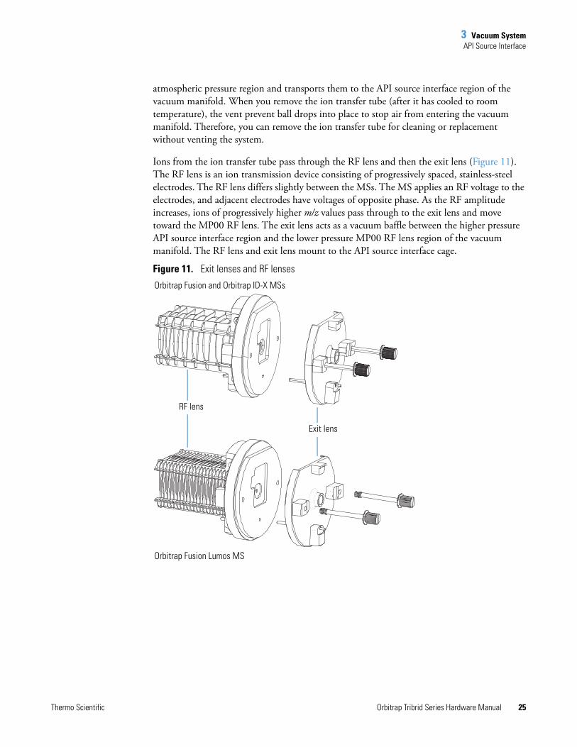
Ions from the ion transfer tube pass through the RF lens and then the exit lens (Figure 11). The RF lens is an ion transmission device consisting of progressively spaced, stainless-steel electrodes. The RF lens differs slightly between the MSs. The MS applies an RF voltage to the electrodes, and adjacent electrodes have voltages of opposite phase. As the RF amplitude increases, ions of progressively higher m/z values pass through to the exit lens and move toward the MP00 RF lens. The exit lens acts as a vacuum baffle between the higher pressure API source interface region and the lower pressure MP00 RF lens region of the vacuum manifold. The RF lens and exit lens mount to the API source interface cage.
Figure 11. Exit lenses and RF lenses
Exit lens
RF lens
Orbitrap Fusion and Orbitrap ID-X MSs
Orbitrap Fusion Lumos MS

3 Vacuum SystemAPI Source Interface
26 Orbitrap Tribrid Series Hardware Manual Thermo Scientific
Thermo Scientific Orbitrap Tribrid Series Hardware Manual 27
4
Ion Transmission and Mass Analysis
This chapter provides a workflow chart that shows the paths for mass analysis through the Orbitrap Tribrid Series MS. It also provides descriptions of the ion optics elements, the three mass analyzers, and the ion detection system.
Contents
• Workflow for Mass Analysis
• Ion Optics
• Mass Analyzers
• Ion Detection Systems
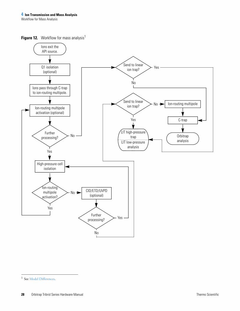
Workflow for Mass AnalysisFigure 12 shows the possible mass analysis paths through the Orbitrap Tribrid Series MS.
4 Ion Transmission and Mass AnalysisWorkflow for Mass Analysis
28 Orbitrap Tribrid Series Hardware Manual Thermo Scientific
Figure 12. Workflow for mass analysis1
1 See Model Differences.
Ion-routing multipole activation (optional)
Further processing?
Send to linear ion trap?
Ion-routing multipole
activation?
Ion-routing multipole
C-trap
LIT high-pressure trap
Yes
No
Further processing? Yes
LIT low-pressure analysis
Yes
No
Send to linear ion trap?
No
CID/ETD/UVPD (optional)
Orbitrap analysis
Q1 isolation (optional)
Ions pass through C-trap to ion-routing multipole.
High-pressure cell isolation
Ions exit the API source.
Yes
No
Yes
No
4 Ion Transmission and Mass AnalysisIon Optics
Thermo Scientific Orbitrap Tribrid Series Hardware Manual 29
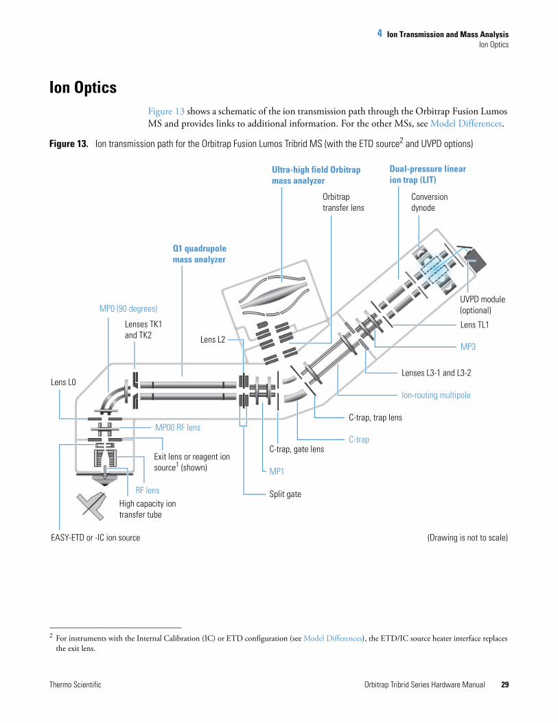
Ion OpticsFigure 13 shows a schematic of the ion transmission path through the Orbitrap Fusion Lumos MS and provides links to additional information. For the other MSs, see Model Differences.
Figure 13. Ion transmission path for the Orbitrap Fusion Lumos Tribrid MS (with the ETD source2 and UVPD options)
2 For instruments with the Internal Calibration (IC) or ETD configuration (see Model Differences), the ETD/IC source heater interface replaces the exit lens.
Dual-pressure linear ion trap (LIT)
Conversion dynode
Lens TL1
MP3
Lenses L3-1 and L3-2
Ion-routing multipole
C-trap, trap lens
C-trapC-trap, gate lens
Ultra-high field Orbitrap mass analyzer
Orbitrap transfer lens
MP1
Split gate
Lens L2
Lens L0
MP00 RF lens
Exit lens or reagent ion source1 (shown)
RF lens
EASY-ETD or -IC ion source
High capacity ion transfer tube
UVPD module (optional)
Q1 quadrupole mass analyzer
Lenses TK1 and TK2
MP0 (90 degrees)
(Drawing is not to scale)
4 Ion Transmission and Mass AnalysisIon Optics
30 Orbitrap Tribrid Series Hardware Manual Thermo Scientific
The ion optics focus and accelerate the gas-phase sample ions into the designated mass analyzer, where they are isolated and ejected according to their m/z values. See these topics:
• MP00 Ion Optics
• MP0 Ion Optics
• MP1 Ion Optics
• Curved Linear Trap
• Ion-Routing Multipole
• MP3 Ion Optics
• DC Offset Voltages
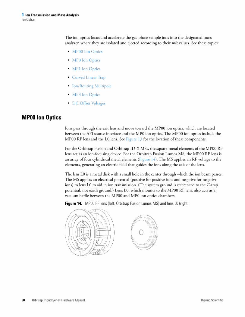
MP00 Ion Optics
Ions pass through the exit lens and move toward the MP00 ion optics, which are located between the API source interface and the MP0 ion optics. The MP00 ion optics include the MP00 RF lens and the L0 lens. See Figure 13 for the location of these components.
For the Orbitrap Fusion and Orbitrap ID-X MSs, the square-metal elements of the MP00 RF lens act as an ion-focusing device. For the Orbitrap Fusion Lumos MS, the MP00 RF lens is an array of four cylindrical metal elements (Figure 14). The MS applies an RF voltage to the elements, generating an electric field that guides the ions along the axis of the lens.
The lens L0 is a metal disk with a small hole in the center through which the ion beam passes. The MS applies an electrical potential (positive for positive ions and negative for negative ions) to lens L0 to aid in ion transmission. (The system ground is referenced to the C-trap potential, not earth ground.) Lens L0, which mounts to the MP00 RF lens, also acts as a vacuum baffle between the MP00 and MP0 ion optics chambers.
Figure 14. MP00 RF lens (left, Orbitrap Fusion Lumos MS) and lens L0 (right)
4 Ion Transmission and Mass AnalysisIon Optics
Thermo Scientific Orbitrap Tribrid Series Hardware Manual 31
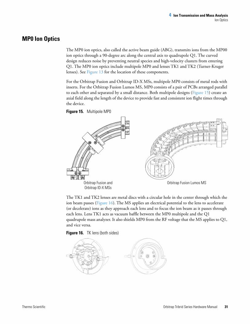
MP0 Ion Optics
The MP0 ion optics, also called the active beam guide (ABG), transmits ions from the MP00 ion optics through a 90-degree arc along the central axis to quadrupole Q1. The curved design reduces noise by preventing neutral species and high-velocity clusters from entering Q1. The MP0 ion optics include multipole MP0 and lenses TK1 and TK2 (Turner-Kruger lenses). See Figure 13 for the location of these components.
For the Orbitrap Fusion and Orbitrap ID-X MSs, multipole MP0 consists of metal rods with inserts. For the Orbitrap Fusion Lumos MS, MP0 consists of a pair of PCBs arranged parallel to each other and separated by a small distance. Both multipole designs (Figure 15) create an axial field along the length of the device to provide fast and consistent ion flight times through the device.
Figure 15. Multipole MP0
The TK1 and TK2 lenses are metal discs with a circular hole in the center through which the ion beam passes (Figure 16). The MS applies an electrical potential to the lens to accelerate (or decelerate) ions as they approach each lens and to focus the ion beam as it passes through each lens. Lens TK1 acts as vacuum baffle between the MP0 multipole and the Q1 quadrupole mass analyzer. It also shields MP0 from the RF voltage that the MS applies to Q1, and vice versa.
Figure 16. TK lens (both sides)
Orbitrap Fusion Lumos MSOrbitrap Fusion and Orbitrap ID-X MSs
4 Ion Transmission and Mass AnalysisIon Optics
32 Orbitrap Tribrid Series Hardware Manual Thermo Scientific
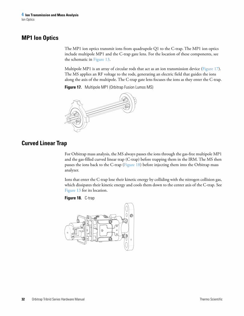
MP1 Ion Optics
The MP1 ion optics transmit ions from quadrupole Q1 to the C-trap. The MP1 ion optics include multipole MP1 and the C-trap gate lens. For the location of these components, see the schematic in Figure 13.
Multipole MP1 is an array of circular rods that act as an ion transmission device (Figure 17). The MS applies an RF voltage to the rods, generating an electric field that guides the ions along the axis of the multipole. The C-trap gate lens focuses the ions as they enter the C-trap.
Figure 17. Multipole MP1 (Orbitrap Fusion Lumos MS)
Curved Linear Trap
For Orbitrap mass analysis, the MS always passes the ions through the gas-free multipole MP1 and the gas-filled curved linear trap (C-trap) before trapping them in the IRM. The MS then passes the ions back to the C-trap (Figure 18) before injecting them into the Orbitrap mass analyzer.
Ions that enter the C-trap lose their kinetic energy by colliding with the nitrogen collision gas, which dissipates their kinetic energy and cools them down to the center axis of the C-trap. See Figure 13 for its location.
Figure 18. C-trap
4 Ion Transmission and Mass AnalysisIon Optics
Thermo Scientific Orbitrap Tribrid Series Hardware Manual 33
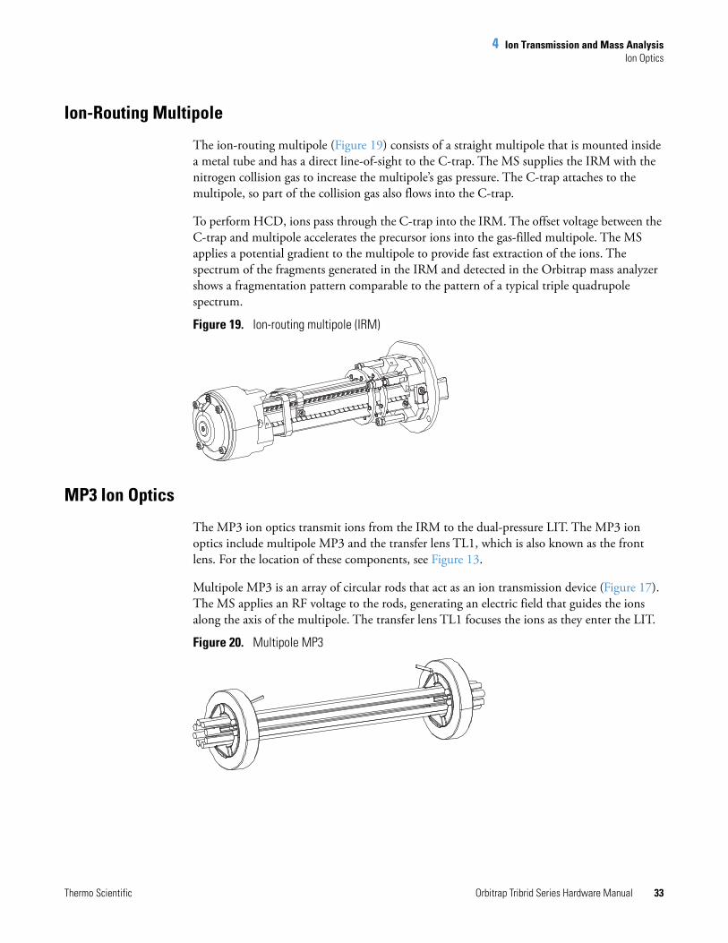
Ion-Routing Multipole
The ion-routing multipole (Figure 19) consists of a straight multipole that is mounted inside a metal tube and has a direct line-of-sight to the C-trap. The MS supplies the IRM with the nitrogen collision gas to increase the multipole’s gas pressure. The C-trap attaches to the multipole, so part of the collision gas also flows into the C-trap.
To perform HCD, ions pass through the C-trap into the IRM. The offset voltage between the C-trap and multipole accelerates the precursor ions into the gas-filled multipole. The MS applies a potential gradient to the multipole to provide fast extraction of the ions. The spectrum of the fragments generated in the IRM and detected in the Orbitrap mass analyzer shows a fragmentation pattern comparable to the pattern of a typical triple quadrupole spectrum.
Figure 19. Ion-routing multipole (IRM)
MP3 Ion Optics
The MP3 ion optics transmit ions from the IRM to the dual-pressure LIT. The MP3 ion optics include multipole MP3 and the transfer lens TL1, which is also known as the front lens. For the location of these components, see Figure 13.
Multipole MP3 is an array of circular rods that act as an ion transmission device (Figure 17). The MS applies an RF voltage to the rods, generating an electric field that guides the ions along the axis of the multipole. The transfer lens TL1 focuses the ions as they enter the LIT.
Figure 20. Multipole MP3
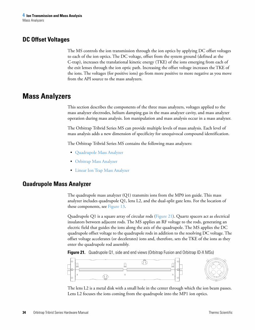
4 Ion Transmission and Mass AnalysisMass Analyzers
34 Orbitrap Tribrid Series Hardware Manual Thermo Scientific
DC Offset Voltages
The MS controls the ion transmission through the ion optics by applying DC offset voltages to each of the ion optics. The DC voltage, offset from the system ground (defined at the C-trap), increases the translational kinetic energy (TKE) of the ions emerging from each of the exit lenses through the ion optic path. Increasing the offset voltage increases the TKE of the ions. The voltages (for positive ions) go from more positive to more negative as you move from the API source to the mass analyzers.
Mass AnalyzersThis section describes the components of the three mass analyzers, voltages applied to the mass analyzer electrodes, helium damping gas in the mass analyzer cavity, and mass analyzer operation during mass analysis. Ion manipulation and mass analysis occur in a mass analyzer.
The Orbitrap Tribrid Series MS can provide multiple levels of mass analysis. Each level of mass analysis adds a new dimension of specificity for unequivocal compound identification.
The Orbitrap Tribrid Series MS contains the following mass analyzers:
• Quadrupole Mass Analyzer
• Orbitrap Mass Analyzer
• Linear Ion Trap Mass Analyzer
Quadrupole Mass Analyzer
The quadrupole mass analyzer (Q1) transmits ions from the MP0 ion guide. This mass analyzer includes quadrupole Q1, lens L2, and the dual-split gate lens. For the location of these components, see Figure 13.
Quadrupole Q1 is a square array of circular rods (Figure 21). Quartz spacers act as electrical insulators between adjacent rods. The MS applies an RF voltage to the rods, generating an electric field that guides the ions along the axis of the quadrupole. The MS applies the DC quadrupole offset voltage to the quadrupole rods in addition to the resolving DC voltage. The offset voltage accelerates (or decelerates) ions and, therefore, sets the TKE of the ions as they enter the quadrupole rod assembly.
Figure 21. Quadrupole Q1, side and end views (Orbitrap Fusion and Orbitrap ID-X MSs)
The lens L2 is a metal disk with a small hole in the center through which the ion beam passes. Lens L2 focuses the ions coming from the quadrupole into the MP1 ion optics.
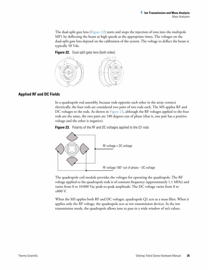
4 Ion Transmission and Mass AnalysisMass Analyzers
Thermo Scientific Orbitrap Tribrid Series Hardware Manual 35
The dual-split gate lens (Figure 22) starts and stops the injection of ions into the multipole MP1 by deflecting the beam at high speeds at the appropriate times. The voltages on the dual-split gate lens depend on the calibration of the system. The voltage to deflect the beam is typically 50 Vdc.
Figure 22. Dual-split gate lens (both sides)
Applied RF and DC Fields
In a quadrupole rod assembly, because rods opposite each other in the array connect electrically, the four rods are considered two pairs of two rods each. The MS applies RF and DC voltages to the rods. As shown in Figure 23, although the RF voltages applied to the four rods are the same, the two pairs are 180 degrees out of phase (that is, one pair has a positive voltage and the other is negative).
Figure 23. Polarity of the RF and DC voltages applied to the Q1 rods
The quadrupole coil module provides the voltages for operating the quadrupole. The RF voltage applied to the quadrupole rods is of constant frequency (approximately 1.1 MHz) and varies from 0 to 10 000 Vac peak-to-peak amplitude. The DC voltage varies from 0 to ±800 V.
When the MS applies both RF and DC voltages, quadrupole Q1 acts as a mass filter. When it applies only the RF voltage, the quadrupole acts as ion transmission devices. In the ion transmission mode, the quadrupole allows ions to pass in a wide window of m/z values.
RF voltage + DC voltage
RF voltage 180° out of phase – DC voltage
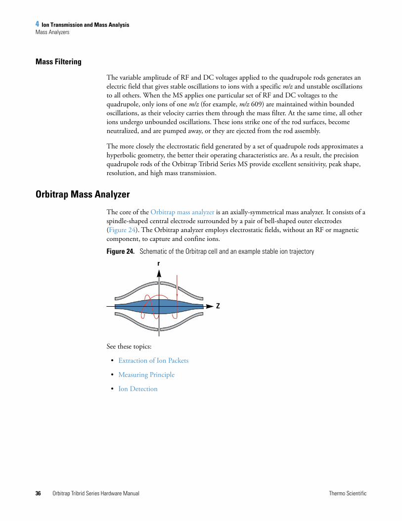
4 Ion Transmission and Mass AnalysisMass Analyzers
36 Orbitrap Tribrid Series Hardware Manual Thermo Scientific
Mass Filtering
The variable amplitude of RF and DC voltages applied to the quadrupole rods generates an electric field that gives stable oscillations to ions with a specific m/z and unstable oscillations to all others. When the MS applies one particular set of RF and DC voltages to the quadrupole, only ions of one m/z (for example, m/z 609) are maintained within bounded oscillations, as their velocity carries them through the mass filter. At the same time, all other ions undergo unbounded oscillations. These ions strike one of the rod surfaces, become neutralized, and are pumped away, or they are ejected from the rod assembly.
The more closely the electrostatic field generated by a set of quadrupole rods approximates a hyperbolic geometry, the better their operating characteristics are. As a result, the precision quadrupole rods of the Orbitrap Tribrid Series MS provide excellent sensitivity, peak shape, resolution, and high mass transmission.
Orbitrap Mass Analyzer
The core of the Orbitrap mass analyzer is an axially-symmetrical mass analyzer. It consists of a spindle-shaped central electrode surrounded by a pair of bell-shaped outer electrodes (Figure 24). The Orbitrap analyzer employs electrostatic fields, without an RF or magnetic component, to capture and confine ions.
Figure 24. Schematic of the Orbitrap cell and an example stable ion trajectory
See these topics:
• Extraction of Ion Packets
• Measuring Principle
• Ion Detection
r
Z
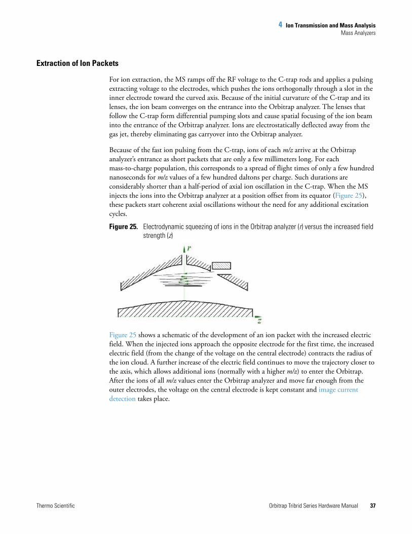
4 Ion Transmission and Mass AnalysisMass Analyzers
Thermo Scientific Orbitrap Tribrid Series Hardware Manual 37
Extraction of Ion Packets
For ion extraction, the MS ramps off the RF voltage to the C-trap rods and applies a pulsing extracting voltage to the electrodes, which pushes the ions orthogonally through a slot in the inner electrode toward the curved axis. Because of the initial curvature of the C-trap and its lenses, the ion beam converges on the entrance into the Orbitrap analyzer. The lenses that follow the C-trap form differential pumping slots and cause spatial focusing of the ion beam into the entrance of the Orbitrap analyzer. Ions are electrostatically deflected away from the gas jet, thereby eliminating gas carryover into the Orbitrap analyzer.
Because of the fast ion pulsing from the C-trap, ions of each m/z arrive at the Orbitrap analyzer’s entrance as short packets that are only a few millimeters long. For each mass-to-charge population, this corresponds to a spread of flight times of only a few hundred nanoseconds for m/z values of a few hundred daltons per charge. Such durations are considerably shorter than a half-period of axial ion oscillation in the C-trap. When the MS injects the ions into the Orbitrap analyzer at a position offset from its equator (Figure 25), these packets start coherent axial oscillations without the need for any additional excitation cycles.
Figure 25. Electrodynamic squeezing of ions in the Orbitrap analyzer (r) versus the increased field strength (z)
Figure 25 shows a schematic of the development of an ion packet with the increased electric field. When the injected ions approach the opposite electrode for the first time, the increased electric field (from the change of the voltage on the central electrode) contracts the radius of the ion cloud. A further increase of the electric field continues to move the trajectory closer to the axis, which allows additional ions (normally with a higher m/z) to enter the Orbitrap. After the ions of all m/z values enter the Orbitrap analyzer and move far enough from the outer electrodes, the voltage on the central electrode is kept constant and image current detection takes place.
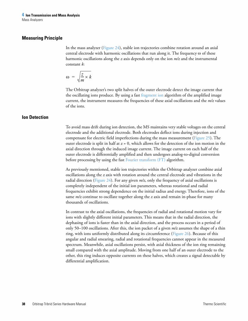
4 Ion Transmission and Mass AnalysisMass Analyzers
38 Orbitrap Tribrid Series Hardware Manual Thermo Scientific
Measuring Principle
In the mass analyzer (Figure 24), stable ion trajectories combine rotation around an axial central electrode with harmonic oscillations that run along it. The frequency of these harmonic oscillations along the z axis depends only on the ion m/z and the instrumental constant k:
The Orbitrap analyzer’s two split halves of the outer electrode detect the image current that the oscillating ions produce. By using a fast fragment ion algorithm of the amplified image current, the instrument measures the frequencies of these axial oscillations and the m/z values of the ions.
Ion Detection
To avoid mass drift during ion detection, the MS maintains very stable voltages on the central electrode and the additional electrode. Both electrodes deflect ions during injection and compensate for electric field imperfections during the mass measurement (Figure 25). The outer electrode is split in half at z = 0, which allows for the detection of the ion motion in the axial direction through the induced image current. The image current on each half of the outer electrode is differentially amplified and then undergoes analog-to-digital conversion before processing by using the fast Fourier transform (FT) algorithm.
As previously mentioned, stable ion trajectories within the Orbitrap analyzer combine axial oscillations along the z axis with rotation around the central electrode and vibrations in the radial direction (Figure 24). For any given m/z, only the frequency of axial oscillations is completely independent of the initial ion parameters, whereas rotational and radial frequencies exhibit strong dependence on the initial radius and energy. Therefore, ions of the same m/z continue to oscillate together along the z axis and remain in-phase for many thousands of oscillations.
In contrast to the axial oscillations, the frequencies of radial and rotational motion vary for ions with slightly different initial parameters. This means that in the radial direction, the dephasing of ions is faster than in the axial direction, and the process occurs in a period of only 50–100 oscillations. After this, the ion packet of a given m/z assumes the shape of a thin ring, with ions uniformly distributed along its circumference (Figure 26). Because of this angular and radial smearing, radial and rotational frequencies cannot appear in the measured spectrum. Meanwhile, axial oscillations persist, with axial thickness of the ion ring remaining small compared with the axial amplitude. Moving from one half of an outer electrode to the other, this ring induces opposite currents on these halves, which creates a signal detectable by differential amplification.
zm---- k=
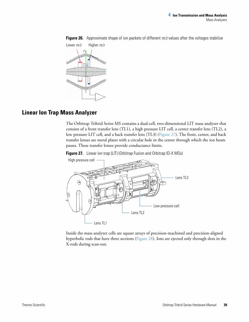
4 Ion Transmission and Mass AnalysisMass Analyzers
Thermo Scientific Orbitrap Tribrid Series Hardware Manual 39
Figure 26. Approximate shape of ion packets of different m/z values after the voltages stabilize
Linear Ion Trap Mass Analyzer
The Orbitrap Tribrid Series MS contains a dual-cell, two-dimensional LIT mass analyzer that consists of a front transfer lens (TL1), a high pressure LIT cell, a center transfer lens (TL2), a low pressure LIT cell, and a back transfer lens (TL3) (Figure 27). The front, center, and back transfer lenses are metal plates with a circular hole in the center through which the ion beam passes. These transfer lenses provide conductance limits.
Figure 27. Linear ion trap (LIT) (Orbitrap Fusion and Orbitrap ID-X MSs)
Inside the mass analyzer cells are square arrays of precision-machined and precision-aligned hyperbolic rods that have three sections (Figure 28). Ions are ejected only through slots in the X-rods during scan-out.
Lower m/z Higher m/z
High pressure cell
Low pressure cell
Lens TL3
Lens TL2
Lens TL1
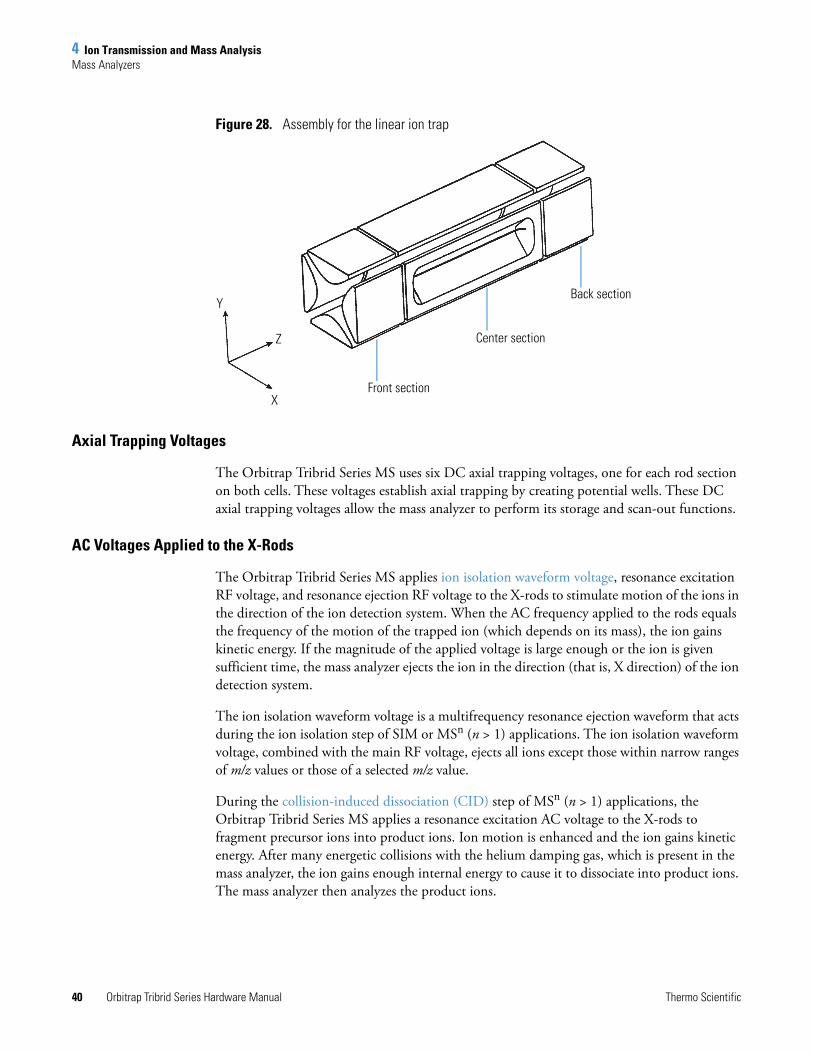
4 Ion Transmission and Mass AnalysisMass Analyzers
40 Orbitrap Tribrid Series Hardware Manual Thermo Scientific
Figure 28. Assembly for the linear ion trap
Axial Trapping Voltages
The Orbitrap Tribrid Series MS uses six DC axial trapping voltages, one for each rod section on both cells. These voltages establish axial trapping by creating potential wells. These DC axial trapping voltages allow the mass analyzer to perform its storage and scan-out functions.
AC Voltages Applied to the X-Rods
The Orbitrap Tribrid Series MS applies ion isolation waveform voltage, resonance excitation RF voltage, and resonance ejection RF voltage to the X-rods to stimulate motion of the ions in the direction of the ion detection system. When the AC frequency applied to the rods equals the frequency of the motion of the trapped ion (which depends on its mass), the ion gains kinetic energy. If the magnitude of the applied voltage is large enough or the ion is given sufficient time, the mass analyzer ejects the ion in the direction (that is, X direction) of the ion detection system.
The ion isolation waveform voltage is a multifrequency resonance ejection waveform that acts during the ion isolation step of SIM or MSn (n > 1) applications. The ion isolation waveform voltage, combined with the main RF voltage, ejects all ions except those within narrow ranges of m/z values or those of a selected m/z value.
During the collision-induced dissociation (CID) step of MSn (n > 1) applications, the Orbitrap Tribrid Series MS applies a resonance excitation AC voltage to the X-rods to fragment precursor ions into product ions. Ion motion is enhanced and the ion gains kinetic energy. After many energetic collisions with the helium damping gas, which is present in the mass analyzer, the ion gains enough internal energy to cause it to dissociate into product ions. The mass analyzer then analyzes the product ions.
Y
X
Z
Back section
Center section
Front section
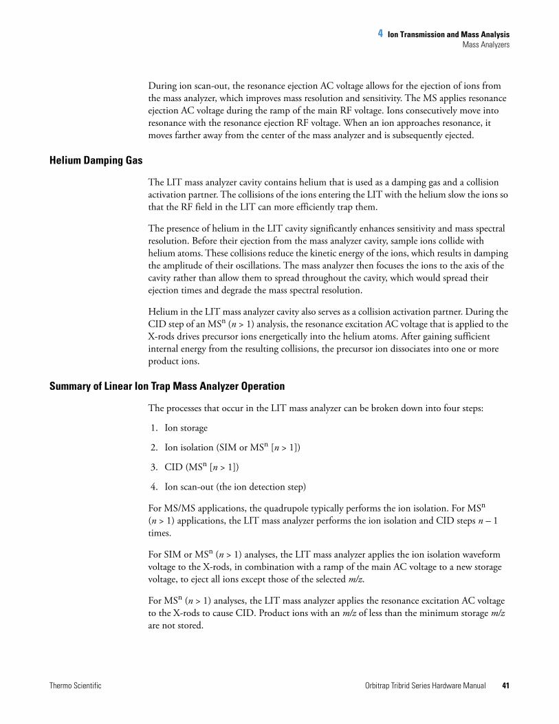
4 Ion Transmission and Mass AnalysisMass Analyzers
Thermo Scientific Orbitrap Tribrid Series Hardware Manual 41
During ion scan-out, the resonance ejection AC voltage allows for the ejection of ions from the mass analyzer, which improves mass resolution and sensitivity. The MS applies resonance ejection AC voltage during the ramp of the main RF voltage. Ions consecutively move into resonance with the resonance ejection RF voltage. When an ion approaches resonance, it moves farther away from the center of the mass analyzer and is subsequently ejected.
Helium Damping Gas
The LIT mass analyzer cavity contains helium that is used as a damping gas and a collision activation partner. The collisions of the ions entering the LIT with the helium slow the ions so that the RF field in the LIT can more efficiently trap them.
The presence of helium in the LIT cavity significantly enhances sensitivity and mass spectral resolution. Before their ejection from the mass analyzer cavity, sample ions collide with helium atoms. These collisions reduce the kinetic energy of the ions, which results in damping the amplitude of their oscillations. The mass analyzer then focuses the ions to the axis of the cavity rather than allow them to spread throughout the cavity, which would spread their ejection times and degrade the mass spectral resolution.
Helium in the LIT mass analyzer cavity also serves as a collision activation partner. During the CID step of an MSn (n > 1) analysis, the resonance excitation AC voltage that is applied to the X-rods drives precursor ions energetically into the helium atoms. After gaining sufficient internal energy from the resulting collisions, the precursor ion dissociates into one or more product ions.
Summary of Linear Ion Trap Mass Analyzer Operation
The processes that occur in the LIT mass analyzer can be broken down into four steps:
1. Ion storage
2. Ion isolation (SIM or MSn [n > 1])
3. CID (MSn [n > 1])
4. Ion scan-out (the ion detection step)
For MS/MS applications, the quadrupole typically performs the ion isolation. For MSn (n > 1) applications, the LIT mass analyzer performs the ion isolation and CID steps n – 1 times.
For SIM or MSn (n > 1) analyses, the LIT mass analyzer applies the ion isolation waveform voltage to the X-rods, in combination with a ramp of the main AC voltage to a new storage voltage, to eject all ions except those of the selected m/z.
For MSn (n > 1) analyses, the LIT mass analyzer applies the resonance excitation AC voltage to the X-rods to cause CID. Product ions with an m/z of less than the minimum storage m/z are not stored.
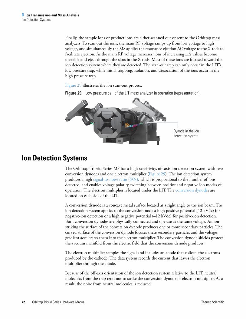
4 Ion Transmission and Mass AnalysisIon Detection Systems
42 Orbitrap Tribrid Series Hardware Manual Thermo Scientific
Finally, the sample ions or product ions are either scanned out or sent to the Orbitrap mass analyzers. To scan out the ions, the main RF voltage ramps up from low voltage to high voltage, and simultaneously the MS applies the resonance ejection AC voltage to the X-rods to facilitate ejection. As the main RF voltage increases, ions of increasing m/z values become unstable and eject through the slots in the X-rods. Most of these ions are focused toward the ion detection system where they are detected. The scan-out step can only occur in the LIT’s low pressure trap, while initial trapping, isolation, and dissociation of the ions occur in the high pressure trap.
Figure 29 illustrates the ion scan-out process.
Figure 29. Low pressure cell of the LIT mass analyzer in operation (representation)
Ion Detection SystemsThe Orbitrap Tribrid Series MS has a high-sensitivity, off-axis ion detection system with two conversion dynodes and one electron multiplier (Figure 29). The ion detection system produces a high signal-to-noise ratio (S/N), which is proportional to the number of ions detected, and enables voltage polarity switching between positive and negative ion modes of operation. The electron multiplier is located under the LIT. The conversion dynodes are located on each side of the LIT.
A conversion dynode is a concave metal surface located at a right angle to the ion beam. The ion detection system applies to the conversion node a high positive potential (12 kVdc) for negative-ion detection or a high negative potential (–12 kVdc) for positive-ion detection. Both conversion dynodes are physically connected and operate at the same voltage. An ion striking the surface of the conversion dynode produces one or more secondary particles. The curved surface of the conversion dynode focuses these secondary particles and the voltage gradient accelerates them into the electron multiplier. The conversion dynode shields protect the vacuum manifold from the electric field that the conversion dynode produces.
The electron multiplier samples the signal and includes an anode that collects the electrons produced by the cathode. The data system records the current that leaves the electron multiplier through the anode.
Because of the off-axis orientation of the ion detection system relative to the LIT, neutral molecules from the trap tend not to strike the conversion dynode or electron multiplier. As a result, the noise from neutral molecules is reduced.
Dynode in the ion detection system
Thermo Scientific Orbitrap Tribrid Series Hardware Manual 43
5
Syringe Pump and Divert/Inject Valve
This chapter describes the external syringe pump and divert/inject valve that ship with the Orbitrap Tribrid Series MS. For information about installing these components, refer to the Getting Connected Guide.
Contents
• Syringe Pump
• Divert/Inject Valve
Syringe PumpThe external Chemyx™ Fusion 100T syringe pump delivers sample solution from an installed syringe, through the sample transfer line (red PEEK), and into the API source. The motorized pusher block (Figure 30) depresses the syringe plunger at the flow rate specified in the data system. (The default flow rate for calibration is 3 μL/min.)
You can start and stop the syringe pump from the data system; refer to the data system Help for instructions. You can also start and stop the syringe pump by pressing the syringe pump buttons.
Note If you choose to provide a syringe pump other than the Fusion 100T, ensure that it can provide a steady, continuous flow of 1–5 μL/min.
In the Tune application version 3.0 and later, you can prime the syringe while it is in the provided syringe pump.
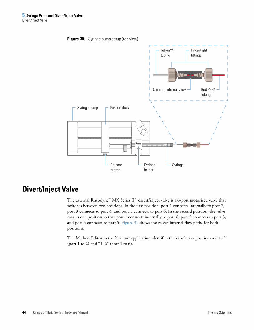
5 Syringe Pump and Divert/Inject ValveDivert/Inject Valve
44 Orbitrap Tribrid Series Hardware Manual Thermo Scientific
Figure 30. Syringe pump setup (top view)
Divert/Inject ValveThe external Rheodyne™ MX Series II™ divert/inject valve is a 6-port motorized valve that switches between two positions. In the first position, port 1 connects internally to port 2, port 3 connects to port 4, and port 5 connects to port 6. In the second position, the valve rotates one position so that port 1 connects internally to port 6, port 2 connects to port 3, and port 4 connects to port 5. Figure 31 shows the valve’s internal flow paths for both positions.
The Method Editor in the Xcalibur application identifies the valve’s two positions as “1–2” (port 1 to 2) and “1–6” (port 1 to 6).
Teflon™ tubing
Fingertight fittings
LC union, internal view Red PEEK tubing
Pusher blockSyringe pump
Release button
Syringe holder
Syringe
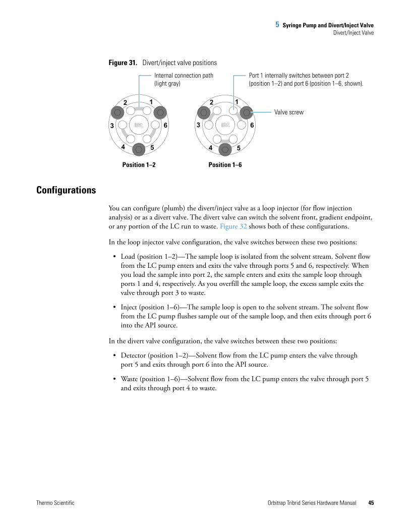
5 Syringe Pump and Divert/Inject ValveDivert/Inject Valve
Thermo Scientific Orbitrap Tribrid Series Hardware Manual 45
Figure 31. Divert/inject valve positions
Configurations
You can configure (plumb) the divert/inject valve as a loop injector (for flow injection analysis) or as a divert valve. The divert valve can switch the solvent front, gradient endpoint, or any portion of the LC run to waste. Figure 32 shows both of these configurations.
In the loop injector valve configuration, the valve switches between these two positions:
• Load (position 1–2)—The sample loop is isolated from the solvent stream. Solvent flow from the LC pump enters and exits the valve through ports 5 and 6, respectively. When you load the sample into port 2, the sample enters and exits the sample loop through ports 1 and 4, respectively. As you overfill the sample loop, the excess sample exits the valve through port 3 to waste.
• Inject (position 1–6)—The sample loop is open to the solvent stream. The solvent flow from the LC pump flushes sample out of the sample loop, and then exits through port 6 into the API source.
In the divert valve configuration, the valve switches between these two positions:
• Detector (position 1–2)—Solvent flow from the LC pump enters the valve through port 5 and exits through port 6 into the API source.
• Waste (position 1–6)—Solvent flow from the LC pump enters the valve through port 5 and exits through port 4 to waste.
3
2 1
54
3
2 1
54
6 6
Internal connection path (light gray)
Port 1 internally switches between port 2 (position 1–2) and port 6 (position 1–6, shown).
Position 1–2 Position 1–6
Valve screw
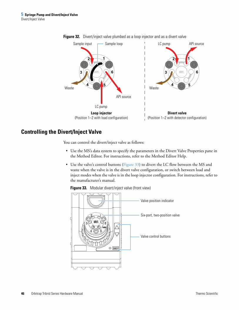
5 Syringe Pump and Divert/Inject ValveDivert/Inject Valve
46 Orbitrap Tribrid Series Hardware Manual Thermo Scientific
Figure 32. Divert/inject valve plumbed as a loop injector and as a divert valve
Controlling the Divert/Inject Valve
You can control the divert/inject valve as follows:
• Use the MS’s data system to specify the parameters in the Divert Valve Properties pane in the Method Editor. For instructions, refer to the Method Editor Help.
• Use the valve’s control buttons (Figure 33) to divert the LC flow between the MS and waste when the valve is in the divert valve configuration, or switch between load and inject modes when the valve is in the loop injector configuration. For instructions, refer to the manufacturer’s manual.
Figure 33. Modular divert/inject valve (front view)
3
2 1
54
6 3
2 1
54
6
Waste Waste
API sourceLC pump
LC pump
API source
Loop injector (Position 1–2 with load configuration)
Sample input
Divert valve (Position 1–2 with detector configuration)
Sample loop
Valve control buttons
Valve position indicator
Six-port, two-position valve

Thermo Scientific Orbitrap Tribrid Series Hardware Manual 47
6
System Shutdown, Startup, and Reset
When you are not using the Orbitrap Tribrid Series system for short periods of time, place the MS in standby mode. For longer periods, for example, two or more months, you can shut it down completely. In addition, many maintenance procedures require shutting down the MS completely.
Contents
• Shutting Down the System in an Emergency
• Placing the Mass Spectrometer in Standby Mode
• Turning On the Mass Spectrometer
• Shutting Down the Mass Spectrometer System Completely
• Starting the System after a Complete Shutdown
• Resetting the Mass Spectrometer
• Resetting Calibration Parameters
• Restarting the Data System
• On/Off Status for MS Components Under Varying Power Conditions
Shutting Down the System in an EmergencyCAUTION To turn off the MS in an emergency, turn off the main power switch located on the right-side power panel (Figure 3). This switch turns off all power to the MS, including the forepump, without harming components within the instrument. However, do not use this method as part of the standard shutdown procedure. Instead, see Shutting Down the Mass Spectrometer System Completely.
To turn off the LC, autosampler, and data system computer in an emergency, use their respective on/off switch or button.
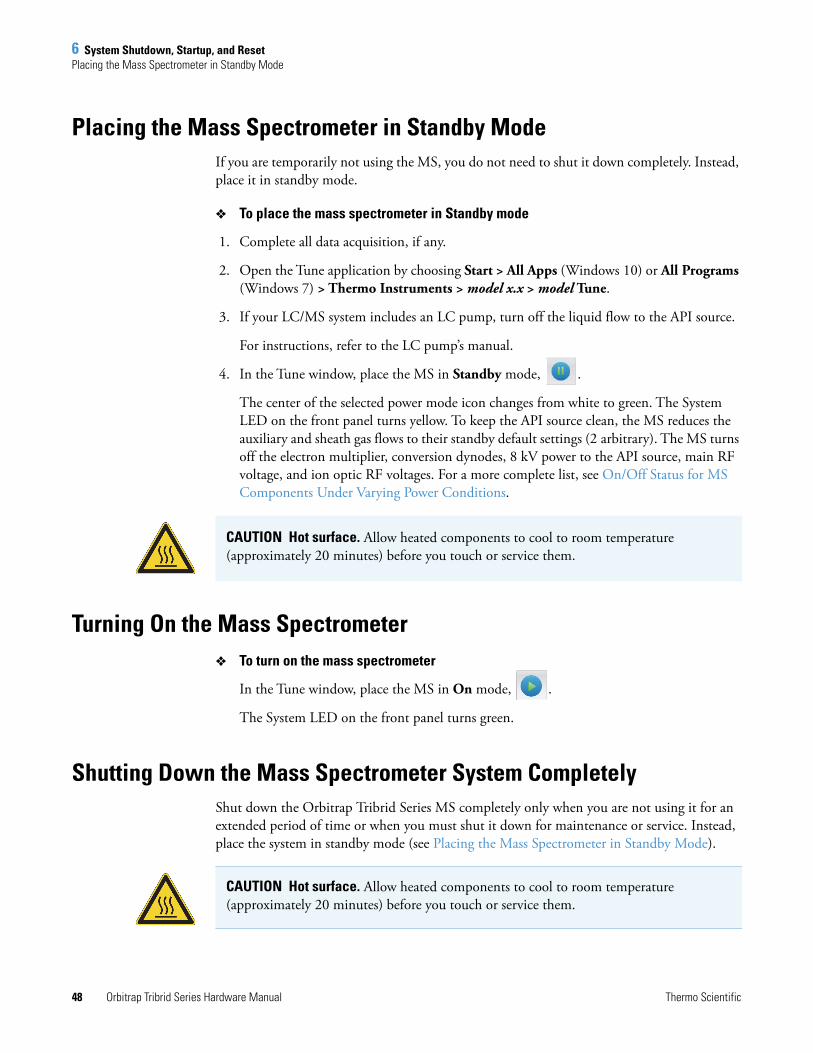
6 System Shutdown, Startup, and ResetPlacing the Mass Spectrometer in Standby Mode
48 Orbitrap Tribrid Series Hardware Manual Thermo Scientific
Placing the Mass Spectrometer in Standby ModeIf you are temporarily not using the MS, you do not need to shut it down completely. Instead, place it in standby mode.
To place the mass spectrometer in Standby mode
1. Complete all data acquisition, if any.
2. Open the Tune application by choosing Start > All Apps (Windows 10) or All Programs (Windows 7) > Thermo Instruments > model x.x > model Tune.
3. If your LC/MS system includes an LC pump, turn off the liquid flow to the API source.
For instructions, refer to the LC pump’s manual.
4. In the Tune window, place the MS in Standby mode, .
The center of the selected power mode icon changes from white to green. The System LED on the front panel turns yellow. To keep the API source clean, the MS reduces the auxiliary and sheath gas flows to their standby default settings (2 arbitrary). The MS turns off the electron multiplier, conversion dynodes, 8 kV power to the API source, main RF voltage, and ion optic RF voltages. For a more complete list, see On/Off Status for MS Components Under Varying Power Conditions.
Turning On the Mass Spectrometer To turn on the mass spectrometer
In the Tune window, place the MS in On mode, .
The System LED on the front panel turns green.
Shutting Down the Mass Spectrometer System CompletelyShut down the Orbitrap Tribrid Series MS completely only when you are not using it for an extended period of time or when you must shut it down for maintenance or service. Instead, place the system in standby mode (see Placing the Mass Spectrometer in Standby Mode).
CAUTION Hot surface. Allow heated components to cool to room temperature (approximately 20 minutes) before you touch or service them.
CAUTION Hot surface. Allow heated components to cool to room temperature (approximately 20 minutes) before you touch or service them.
6 System Shutdown, Startup, and ResetShutting Down the Mass Spectrometer System Completely
Thermo Scientific Orbitrap Tribrid Series Hardware Manual 49
To shut down the mass spectrometer completely
1. Follow the procedure, Placing the Mass Spectrometer in Standby Mode.
2. Place the electronics service switch in the Service Mode (down) position.
This turns off all LEDs on the front panel and the power to the nonvacuum system electronics.
3. Turn off the Main Power switch.
The following occurs:
• All power to the MS, including the turbomolecular pumps and the forepump or forepumps, turns off.
• After approximately 5 seconds, power to the vent valve solenoid shuts off, the vent valve opens, and the vacuum manifold vents with dry nitrogen. You can hear a hissing sound.
• After about 2 minutes, the vacuum manifold is at atmospheric pressure.
4. Unplug the MS’s power cord from the electrical outlet.
5. (Optional) Follow the next procedure, To turn off the LC, gases, data system, and autosampler.
To turn off the LC, gases, data system, and autosampler
1. If included, turn off the LC system as described in the LC manual.
2. Turn off the helium and nitrogen gas supplies at their tanks.
3. Shut down the data system computer, and turn off the monitor and printer, if provided.
4. If included, turn off the autosampler by using its On/Off switch.
CAUTION Do not disconnect the power cord at the MS while the other end is still plugged into the electrical outlet.
Tip If you only plan to perform routine or preventive system maintenance on the MS, you do not need to turn off the LC, gases, data system, and autosampler. In this case, the shutdown procedure is complete. However, if you plan to have the system off for an extended period of time, Thermo Fisher Scientific recommends that you also turn off these other parts of the LC/MS system.
6 System Shutdown, Startup, and ResetStarting the System after a Complete Shutdown
50 Orbitrap Tribrid Series Hardware Manual Thermo Scientific
Starting the System after a Complete ShutdownTo start the Orbitrap Tribrid Series system after it has been shut down completely, follow these procedures:
• Starting the LC System
• Starting the Data System
• Starting the Mass Spectrometer
• Starting the Autosampler (if this is a part of the system)
Starting the LC System
To start the LC system, follow the startup procedure described in the manufacturer’s manual.
Starting the Data System
To start the data system
Turn on the computer, monitor, and printer, if provided.
Starting the Mass Spectrometer
Make sure that the data system is running before starting the MS. The MS does not operate until it receives instructions from the data system.
To start the mass spectrometer
1. Turn on the flows for the helium and nitrogen gases at their tanks, if they are off.
2. Ensure that the Main Power switch is off and that the electronics service switch is in the Service Mode position.
3. Plug in the power cord for the MS.
4. Turn on the Main Power switch.
This turns on the forepump or forepumps and the turbomolecular pumps. All LEDs on the front panel are off.
5. If the MS was turned off for an extended period of time, follow the procedures in Pumping Down the Mass Spectrometer. Otherwise, wait at least 1 hour to allow the MS to pump down.
6. Place the electronics service switch in the Operating Mode (up) position.
Note Do not turn on the liquid flow to the MS at this point in the procedure.
6 System Shutdown, Startup, and ResetStarting the System after a Complete Shutdown
Thermo Scientific Orbitrap Tribrid Series Hardware Manual 51
The following occurs:
• The Power LED on the front panel turns green to indicate that the electronics have power. However, the electron multiplier, conversion dynodes, 8 kV power to the API source, main RF voltage, and ion optic RF voltage remain off.
• After several more seconds, the Communication LED turns yellow and then green to indicate that the MS and the data system are communicating. Make sure that the instrument console window is active. The data system transfers operational software to the MS.
• After a few minutes, the System LED turns yellow to indicate the software transfer from the data system to the MS is complete and that the MS is in standby mode. When you change the mode from standby to on, the System LED turns green to indicate that the MS is functional.
Starting the Autosampler
Turn on the autosampler by using its on/off power switch. If necessary, configure the autosampler. For procedures for placing sample vials, preparing solvent and waste containers, installing syringes, and so on, refer to the autosampler manual. The Getting Connected Guide provides procedures for connecting the MS to the autosampler by using a contact closure cable.
IMPORTANT On the front panel, the Vacuum LED illuminates green only when these gauges are on and register below the indicated pressure threshold:
• Source Pressure gauge—Below 3.0 Torr (Orbitrap Fusion and Orbitrap ID-X MSs) or 4.5 Torr (Orbitrap Fusion Lumos MS) as applicable
• Ion Gauge Pressure gauge—Below 1.5 × 10⁻⁴ Torr
• UHV Pressure gauge (Orbitrap)—Below 5 × 10⁻⁸ Torr
To ensure that the calibrations are correct, wait until the vacuum system is optimized completely, which takes approximately 15–24 hours of continuous pumping.
6 System Shutdown, Startup, and ResetResetting the Mass Spectrometer
52 Orbitrap Tribrid Series Hardware Manual Thermo Scientific
Resetting the Mass SpectrometerIn the unlikely event that communication is lost between the MS and data system computer, you can reset the MS by using the reset button located on the left-side communications panel.
The following procedure assumes that power to the MS and data system computer are on and that both are operational. If the MS, data system computer, or both are off, see Starting the System after a Complete Shutdown.
To reset the mass spectrometer
Hold down the reset button for 3 seconds.
The following occurs:
• The embedded computer restarts. All LEDs on the front panel turn off except the Power LED.
• After several more seconds, the Communication LED turns yellow and then green to indicate that the MS and the data system are communicating. The data system transfers operational software to the MS.
• After a few minutes, the System LED turns yellow to indicate that the software transfer from the data system to the MS is complete and that the MS is in standby mode. Or, the System LED turns green to indicate that the MS is functional.
Resetting Calibration ParametersIf you must reset the calibration parameters to their factory default values, contact Thermo Fisher Scientific Technical Support for assistance.
IMPORTANT
• Before resetting the instrument parameters to their default values, make sure that the system problems you are experiencing are not due to improper API source settings (such as spray voltage, sheath and auxiliary gas flow, or ion transfer tube temperature).
• If you reset the instrument to the factory calibration settings, always repeat the calibration of the internal electronic devices as specified in the Getting Started Guide. Otherwise, all instrument calibrations might produce incorrect results.
6 System Shutdown, Startup, and ResetRestarting the Data System
Thermo Scientific Orbitrap Tribrid Series Hardware Manual 53
Restarting the Data SystemIf possible, use the Windows restart procedure to shut down and restart the data system so that Windows can properly close applications and save changes to any open Thermo application.
To restart the data system by using Windows
1. On the Windows taskbar, choose Start, and then click the arrow next to Shut Down.
2. Choose Restart, and then click OK.
To restart the data system by using the power button
1. Press the power button on the data system computer.
2. Wait at least 20 seconds after the computer shuts down.
3. Press the power button again.
Note After you reset the data system, the communications link between the data system and the MS is automatically reestablished. When this occurs, the Communication LED turns yellow and then green. If the system is unable to reestablish the communications link, hold down the reset button for 3 seconds.
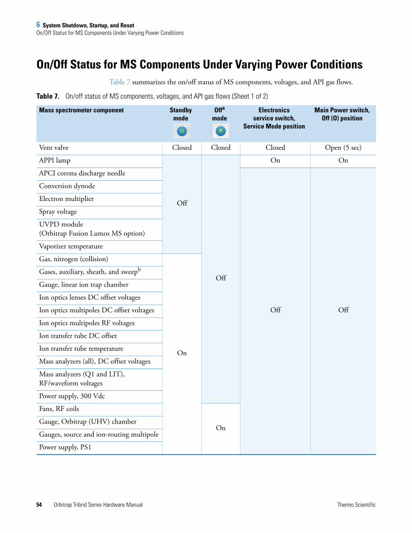
6 System Shutdown, Startup, and ResetOn/Off Status for MS Components Under Varying Power Conditions
54 Orbitrap Tribrid Series Hardware Manual Thermo Scientific
On/Off Status for MS Components Under Varying Power ConditionsTable 7 summarizes the on/off status of MS components, voltages, and API gas flows.
Table 7. On/off status of MS components, voltages, and API gas flows (Sheet 1 of 2)
Mass spectrometer component Standby mode
Offa
mode Electronics
service switch,Service Mode position
Main Power switch,Off (O) position
Vent valve Closed Closed Closed Open (5 sec)
APPI lamp
Off
Off
On On
APCI corona discharge needle
Off Off
Conversion dynode
Electron multiplier
Spray voltage
UVPD module (Orbitrap Fusion Lumos MS option)
Vaporizer temperature
Gas, nitrogen (collision)
On
Gases, auxiliary, sheath, and sweepb
Gauge, linear ion trap chamber
Ion optics lenses DC offset voltages
Ion optics multipoles DC offset voltages
Ion optics multipoles RF voltages
Ion transfer tube DC offset
Ion transfer tube temperature
Mass analyzers (all), DC offset voltages
Mass analyzers (Q1 and LIT), RF/waveform voltages
Power supply, 300 Vdc
Fans, RF coils
OnGauge, Orbitrap (UHV) chamber
Gauges, source and ion-routing multipole
Power supply, PS1
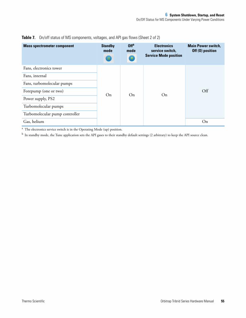
6 System Shutdown, Startup, and ResetOn/Off Status for MS Components Under Varying Power Conditions
Thermo Scientific Orbitrap Tribrid Series Hardware Manual 55
Fans, electronics tower
On On OnOff
Fans, internal
Fans, turbomolecular pumps
Forepump (one or two)
Power supply, PS2
Turbomolecular pumps
Turbomolecular pump controller
Gas, helium Ona The electronics service switch is in the Operating Mode (up) position.b In standby mode, the Tune application sets the API gases to their standby default settings (2 arbitrary) to keep the API source clean.
Table 7. On/off status of MS components, voltages, and API gas flows (Sheet 2 of 2)
Mass spectrometer component Standby mode
Offa
mode Electronics
service switch,Service Mode position
Main Power switch,Off (O) position

6 System Shutdown, Startup, and ResetOn/Off Status for MS Components Under Varying Power Conditions
56 Orbitrap Tribrid Series Hardware Manual Thermo Scientific
Thermo Scientific Orbitrap Tribrid Series Hardware Manual 57
7
Daily Operation
To ensure the proper operation of the Orbitrap Tribrid Series system, Thermo Fisher Scientific recommends that you perform daily preventive maintenance. This chapter specifies the items to check before operating the system and the cleaning procedures to perform after completing the analyses.
Clean the ion sweep cone, the spray cone, and the ion transfer tube on a regular basis to prevent corrosion and to maintain optimum performance of the API source; see Cleaning the Ion Sweep Cone, Spray Cone, and Ion Transfer Tube. If you use a mobile phase that contains a nonvolatile buffer or inject high concentrations of sample, you might need to clean these parts more often. You do not need to clean the system to flush the ion sweep cone and ion transfer tube.
Contents
• Before Operating the Orbitrap Tribrid Series System
• After Operating the Orbitrap Tribrid Series System
Note You do not need to calibrate the Orbitrap Tribrid Series system as part of your daily routine. Generally, you must calibrate the MS every one to three months of operation for optimum performance over the entire mass range of the mass detector.
For information about calibration, refer to the Getting Started Guide.
7 Daily OperationBefore Operating the Orbitrap Tribrid Series System
58 Orbitrap Tribrid Series Hardware Manual Thermo Scientific
Before Operating the Orbitrap Tribrid Series SystemFollow these preventive maintenance procedures every day before beginning the first analysis:
• Checking the System Mode
• Checking the Vacuum Pressure Levels
• Checking the Gas Supplies
• Checking the oil level of the forepumps (See Maintaining the Forepump.)
Checking the System Mode
Make sure that the system is turned on. See Turning On the Mass Spectrometer.
Checking the Vacuum Pressure Levels
Before daily operation begins, check the vacuum pressure levels and check for major air leaks in the system. A major air leak can indicate insufficient pressure levels to turn on the system. In the Tune window, a green square, , indicates that the readback value is good.
To check the vacuum pressures
Make sure that the Vacuum LED on the front of the MS is green, which indicates that the pressure gauges are within their threshold values.
To check the system for major air leaks
Listen for a rush of air or a hissing sound coming from the MS.
Possible causes of a major leak might be a loose or disconnected fitting, an improperly positioned O-ring, or an open valve.
CAUTION For proper performance, operate the system at the proper vacuum levels. Poor vacuum levels can cause reduced sensitivity and reduced electron multiplier life.
IMPORTANT
• See page 51 for the gauges’ threshold values. If the readback values are higher than normal, there might be an air leak or the helium flow might be insufficient.
• If the UHV pressure is above 5 × 10⁻⁸ Torr in the analyzer region and the system restarted within the last 30 to 60 minutes, wait another 30 minutes and recheck the pressure. If the pressure decreases with time, check the pressure periodically until it is within the typical range for the MS.
• If the pressure remains high, the system might have an air leak.
7 Daily OperationAfter Operating the Orbitrap Tribrid Series System
Thermo Scientific Orbitrap Tribrid Series Hardware Manual 59
To fix an air leak
1. Shut down the system (see Shutting Down the Mass Spectrometer System Completely).
2. Visually inspect the vacuum system and vacuum lines for leaks.
3. Check each fitting and flange on the system for tightness and tighten any that are loose.
Do not tighten fittings indiscriminately. Pay particular attention to fittings that have been changed recently or to fittings that have been subjected to heating and cooling.
Checking the Gas Supplies
Check the helium gas tank’s regulator. Make sure that there is sufficient gas for the analysis, which is a minimum of 3447 kPa (500 psi) on the high pressure gauge of the regulator. If necessary, replace the tank. Verify that the pressure of helium gas reaching the MS is 275 ±70 kPa (40 ±10 psi). If necessary, adjust the pressure with the tank pressure regulator.
Check the nitrogen gas supply on the regulator of the nitrogen gas tank or liquid nitrogen boil-off tank. Make sure that there is sufficient gas for the analysis. If necessary, replace the tank. Verify that the pressures of nitrogen gases reaching the MS are as follows:
• 690 ±140 kPa (100 ±20 psi) for the HP nitrogen gas pressure
• 345 ±70 kPa (50 ±10 psi) for the UHP nitrogen gas pressure
If necessary, adjust the pressures with the tank pressure regulators.
For additional gas information, refer to the Preinstallation Requirements Guide.
After Operating the Orbitrap Tribrid Series SystemAfter operating the system, follow these preventive maintenance procedures every day, unless otherwise indicated:
• Flushing the Inlet Components (as needed)
• Purging the Oil in the Forepump
• Emptying the Solvent Waste Container
• Placing the System in Standby Mode
Note When operating 24 hours and 7 days a week, typical daily consumption of nitrogen gas is as follows:
• UHP nitrogen: approximately 46 L/day (1.62 ft3)
• HP nitrogen: 11 500–26 700 L (406–943 ft3)
7 Daily OperationAfter Operating the Orbitrap Tribrid Series System
60 Orbitrap Tribrid Series Hardware Manual Thermo Scientific
Flushing the Inlet Components
This section describes how to flush the syringe and the inlet components (sample transfer line, sample tube, and spray insert) at the end of each work day (or more often if you suspect they are contaminated). You can also use an LC pump to flush the 50:50 methanol/water solution through the inlet components to the API source at a flow rate of 200–400 μL/min for approximately 15 minutes.
To flush the inlet components
1. Turn off the liquid flow from the syringe pump.
2. Place the MS in Standby mode.
3. Remove the syringe from the syringe pump as follows:
a. Lift the syringe holder off of the syringe.
b. Press the pusher block’s release button and slide the block to the left.
c. Remove the syringe from the holder.
d. Carefully remove the syringe needle from the Teflon tube on the syringe adapter assembly.
4. Rinse the syringe with a solution of 50:50 methanol/water.
5. Flush the sample transfer line, sample tube, and spray insert as follows:
a. Load the clean syringe with a solution of 0.1% formic acid in 50:50 methanol/water (or another appropriate solvent).
b. Carefully reinsert the syringe needle into the Teflon tube on the syringe adapter assembly.
c. Slowly depress the syringe plunger to flush the solution through the sample transfer line, sample tube, and spray insert.
d. Remove the syringe needle from the syringe adapter assembly.
This completes the procedure to flush the inlet components.
Tip You do not need to flush the inlet components daily. However, if a mass spectrum shows unwanted contamination peaks, follow this procedure.
CAUTION When the MS’s ion transfer tube is installed, do not flush it with cleaning solution, which flushes the residue into the MS.
7 Daily OperationAfter Operating the Orbitrap Tribrid Series System
Thermo Scientific Orbitrap Tribrid Series Hardware Manual 61
Purging the Oil in the Forepump
Purge (decontaminate) the oil in the forepump daily to remove water and other dissolved chemicals, which can cause corrosion and decrease the lifetime or the performance of the forepump. For instructions, refer to the forepump’s documentation.
The best time to purge the oil is at the end of the working day after you flush the inlet components. Remember to close the purge valve before continuing normal operation.
Emptying the Solvent Waste Container
Check the solvent level in the solvent waste container daily. If necessary, empty the container and dispose of the solvent waste according to local and national regulations.
Placing the System in Standby Mode
After you complete the daily maintenance procedures, place the MS in standby mode (page 48).

7 Daily OperationAfter Operating the Orbitrap Tribrid Series System
62 Orbitrap Tribrid Series Hardware Manual Thermo Scientific
Thermo Scientific Orbitrap Tribrid Series Hardware Manual 63
8
Maintenance
You are responsible for performing routine maintenance procedures to ensure optimum performance of the Orbitrap Tribrid Series MS. Optimum performance depends on the maintenance of all parts of the instrument.
For a list of replaceable parts, see Chapter 9, “Replaceable Parts.”
Contents
• Maintenance Schedule
• Guidelines
• Tools and Supplies
• Maintaining the API Source Housing
• Maintaining the API Source Interface
• Maintaining the Forepump
• Maintaining the Air Filter
• Pumping Down the Mass Spectrometer
CAUTION Heavy object. The Orbitrap Tribrid Series MS, excluding its workbench, weighs over 227 kg (500 lb). Never try to detach and move the instrument from its workbench; you can suffer personal injury or damage the instrument. For additional information, contact Thermo Fisher Scientific Technical Support.
CAUTION Before performing instrument maintenance, either shut down the MS completely or place it in Standby mode as specified in the applicable procedure. Then, allow heated components to cool to room temperature (approximately 20 minutes) before you touch or service them.
Note The following components are slightly different between the MSs: sweep cone, ion transfer tube, API source interface, RF lens, MP00 RF lens, and lens L0. Unless otherwise noted, use the Orbitrap Fusion MS procedures.
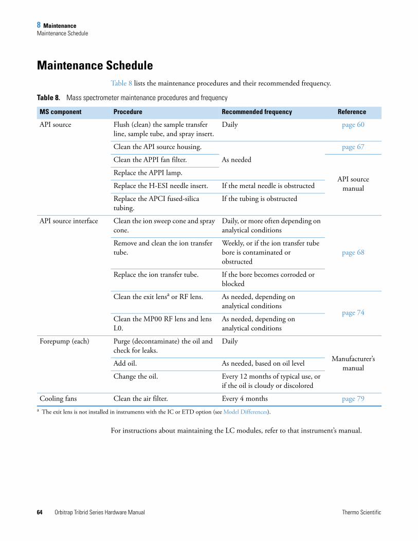
8 MaintenanceMaintenance Schedule
64 Orbitrap Tribrid Series Hardware Manual Thermo Scientific
Maintenance ScheduleTable 8 lists the maintenance procedures and their recommended frequency.
For instructions about maintaining the LC modules, refer to that instrument’s manual.
Table 8. Mass spectrometer maintenance procedures and frequency
MS component Procedure Recommended frequency Reference
API source Flush (clean) the sample transfer line, sample tube, and spray insert.
Daily page 60
Clean the API source housing.
As needed
page 67
Clean the APPI fan filter.
API source manual
Replace the APPI lamp.
Replace the H-ESI needle insert. If the metal needle is obstructed
Replace the APCI fused-silica tubing.
If the tubing is obstructed
API source interface Clean the ion sweep cone and spray cone.
Daily, or more often depending on analytical conditions
page 68Remove and clean the ion transfer tube.
Weekly, or if the ion transfer tube bore is contaminated or obstructed
Replace the ion transfer tube. If the bore becomes corroded or blocked
Clean the exit lensa or RF lens.
a The exit lens is not installed in instruments with the IC or ETD option (see Model Differences).
As needed, depending on analytical conditions
page 74Clean the MP00 RF lens and lens L0.
As needed, depending on analytical conditions
Forepump (each) Purge (decontaminate) the oil and check for leaks.
Daily
Manufacturer’s manualAdd oil. As needed, based on oil level
Change the oil. Every 12 months of typical use, or if the oil is cloudy or discolored
Cooling fans Clean the air filter. Every 4 months page 79
8 MaintenanceGuidelines
Thermo Scientific Orbitrap Tribrid Series Hardware Manual 65
GuidelinesFor optimal results, follow these guidelines when performing the procedures in this chapter:
• Always wear a new pair of lint- and powder-free gloves when handling internal components. Never reuse gloves after you remove them because the surface contaminants on them recontaminate clean parts.
• Always place the components on a clean, lint-free work surface.
• Have nearby the necessary tools, supplies, and replacement parts (when applicable).
• Never overtighten a screw or use excessive force.
• Proceed methodically.
Tools and SuppliesThe Orbitrap Tribrid Series MS requires very few tools to perform routine maintenance procedures. You can remove and disassemble many of the components by hand. Table 9 lists the necessary chemicals, tools, and equipment for maintaining the instrument. (One of the tools is in the Calibration Kit.) In addition, you can use the contents of the PM Cleaning Kit (P/N 70111-62112).
IMPORTANT
• Put on a new pair of lint- and powder-free gloves before starting each removal, cleaning, and reinstallation procedure.
• Make sure that you do not introduce any scratches or surface abrasions while handling the API source interface components. Even small scratches can affect performance if they are close to the ion transmission path. Avoid using tools, such as metal pliers, that might scratch these components.
CAUTION To prevent corrosion, do not use nitric acid to clean metal parts.
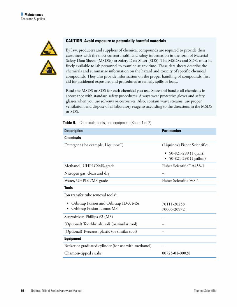
8 MaintenanceTools and Supplies
66 Orbitrap Tribrid Series Hardware Manual Thermo Scientific
CAUTION Avoid exposure to potentially harmful materials.
By law, producers and suppliers of chemical compounds are required to provide their customers with the most current health and safety information in the form of Material Safety Data Sheets (MSDSs) or Safety Data Sheet (SDS). The MSDSs and SDSs must be freely available to lab personnel to examine at any time. These data sheets describe the chemicals and summarize information on the hazard and toxicity of specific chemical compounds. They also provide information on the proper handling of compounds, first aid for accidental exposure, and procedures to remedy spills or leaks.
Read the MSDS or SDS for each chemical you use. Store and handle all chemicals in accordance with standard safety procedures. Always wear protective gloves and safety glasses when you use solvents or corrosives. Also, contain waste streams, use proper ventilation, and dispose of all laboratory reagents according to the directions in the MSDS or SDS.
Table 9. Chemicals, tools, and equipment (Sheet 1 of 2)
Description Part number
Chemicals
Detergent (for example, Liquinox™) (Liquinox) Fisher Scientific:
• 50-821-299 (1 quart)• 50-821-298 (1 gallon)
Methanol, UHPLC/MS-grade Fisher Scientific™ A458-1
Nitrogen gas, clean and dry –
Water, UHPLC/MS-grade Fisher Scientific W8-1
Tools
Ion transfer tube removal toolsa:
• Orbitrap Fusion and Orbitrap ID-X MSs• Orbitrap Fusion Lumos MS
70111-20258 70005-20972
Screwdriver, Phillips #2 (M3) –
(Optional) Toothbrush, soft (or similar tool) –
(Optional) Tweezers, plastic (or similar tool) –
Equipment
Beaker or graduated cylinder (for use with methanol) –
Chamois-tipped swabs 00725-01-00028
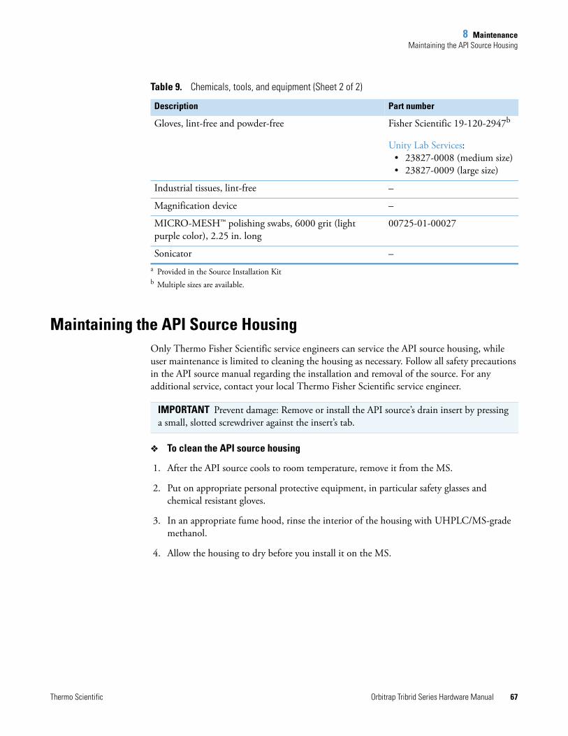
8 MaintenanceMaintaining the API Source Housing
Thermo Scientific Orbitrap Tribrid Series Hardware Manual 67
Maintaining the API Source HousingOnly Thermo Fisher Scientific service engineers can service the API source housing, while user maintenance is limited to cleaning the housing as necessary. Follow all safety precautions in the API source manual regarding the installation and removal of the source. For any additional service, contact your local Thermo Fisher Scientific service engineer.
To clean the API source housing
1. After the API source cools to room temperature, remove it from the MS.
2. Put on appropriate personal protective equipment, in particular safety glasses and chemical resistant gloves.
3. In an appropriate fume hood, rinse the interior of the housing with UHPLC/MS-grade methanol.
4. Allow the housing to dry before you install it on the MS.
Gloves, lint-free and powder-free Fisher Scientific 19-120-2947b
Unity Lab Services: • 23827-0008 (medium size)• 23827-0009 (large size)
Industrial tissues, lint-free –
Magnification device –
MICRO-MESH™ polishing swabs, 6000 grit (light purple color), 2.25 in. long
00725-01-00027
Sonicator –a Provided in the Source Installation Kitb Multiple sizes are available.
Table 9. Chemicals, tools, and equipment (Sheet 2 of 2)
Description Part number
IMPORTANT Prevent damage: Remove or install the API source’s drain insert by pressing a small, slotted screwdriver against the insert’s tab.
8 MaintenanceMaintaining the API Source Interface
68 Orbitrap Tribrid Series Hardware Manual Thermo Scientific
Maintaining the API Source InterfaceWhile you or the service engineer can remove and service the API source interface, only the service engineer may service the other internal components.
To maintain the API source interface, follow these procedures:
• Cleaning the Ion Sweep Cone, Spray Cone, and Ion Transfer Tube
• Removing the API Source Interface
• Cleaning the RF Lens, Exit Lens, MP00 RF Lens, and Lens L0
• Reinstalling the API Source Interface
Cleaning the Ion Sweep Cone, Spray Cone, and Ion Transfer Tube
Because buffer salts or high concentrations of sample can cause blockages, you must clean the bore of the ion transfer tube. If pressure in the ion transfer tube and RF lens region (as measured by the Source Pressure gauge) drops considerably below 1 Torr, a blocked ion transfer tube is likely.
Follow these procedures:
1. To remove the ion sweep cone and the ion transfer tube
2. To clean the spray cone and O-ring
3. To clean the ion transfer tube
4. To clean the ion sweep cone
Note Before you continue, read the precautions in Special Notices, Symbols, and Cautions.
IMPORTANT
• Prepare a clean work surface by covering the area with lint-free paper.
• Put on a new pair of lint- and powder-free gloves before starting each of these removal, cleaning, and reinstallation procedures.
CAUTION To prevent corrosion, do not use nitric acid to clean metal parts.
Tip You do not have to vent the system to remove the ion transfer tube.
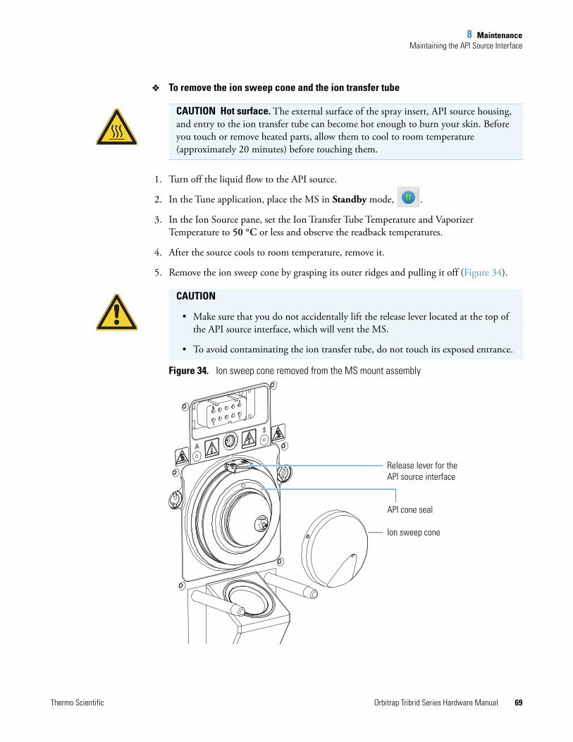
8 MaintenanceMaintaining the API Source Interface
Thermo Scientific Orbitrap Tribrid Series Hardware Manual 69
To remove the ion sweep cone and the ion transfer tube
1. Turn off the liquid flow to the API source.
2. In the Tune application, place the MS in Standby mode, .
3. In the Ion Source pane, set the Ion Transfer Tube Temperature and Vaporizer Temperature to 50 °C or less and observe the readback temperatures.
4. After the source cools to room temperature, remove it.
5. Remove the ion sweep cone by grasping its outer ridges and pulling it off (Figure 34).
Figure 34. Ion sweep cone removed from the MS mount assembly
CAUTION Hot surface. The external surface of the spray insert, API source housing, and entry to the ion transfer tube can become hot enough to burn your skin. Before you touch or remove heated parts, allow them to cool to room temperature (approximately 20 minutes) before touching them.
CAUTION
• Make sure that you do not accidentally lift the release lever located at the top of the API source interface, which will vent the MS.
• To avoid contaminating the ion transfer tube, do not touch its exposed entrance.
Release lever for the API source interface
API cone seal
Ion sweep cone
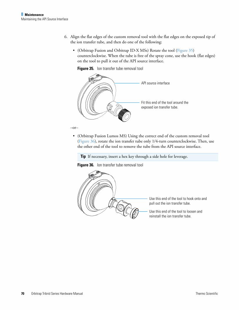
8 MaintenanceMaintaining the API Source Interface
70 Orbitrap Tribrid Series Hardware Manual Thermo Scientific
6. Align the flat edges of the custom removal tool with the flat edges on the exposed tip of the ion transfer tube, and then do one of the following:
• (Orbitrap Fusion and Orbitrap ID-X MSs) Rotate the tool (Figure 35) counterclockwise. When the tube is free of the spray cone, use the hook (flat edges) on the tool to pull it out of the API source interface.
Figure 35. Ion transfer tube removal tool
–or–
• (Orbitrap Fusion Lumos MS) Using the correct end of the custom removal tool (Figure 36), rotate the ion transfer tube only 1/4-turn counterclockwise. Then, use the other end of the tool to remove the tube from the API source interface.
Figure 36. Ion transfer tube removal tool
Tip If necessary, insert a hex key through a side hole for leverage.
Fit this end of the tool around the exposed ion transfer tube.
API source interface
Use this end of the tool to loosen and reinstall the ion transfer tube.
Use this end of the tool to hook onto and pull out the ion transfer tube.
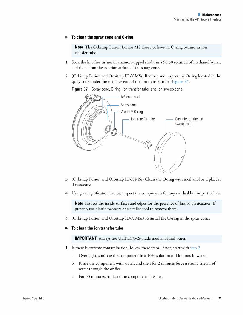
8 MaintenanceMaintaining the API Source Interface
Thermo Scientific Orbitrap Tribrid Series Hardware Manual 71
To clean the spray cone and O-ring
1. Soak the lint-free tissues or chamois-tipped swabs in a 50:50 solution of methanol/water, and then clean the exterior surface of the spray cone.
2. (Orbitrap Fusion and Orbitrap ID-X MSs) Remove and inspect the O-ring located in the spray cone under the entrance end of the ion transfer tube (Figure 37).
Figure 37. Spray cone, O-ring, ion transfer tube, and ion sweep cone
3. (Orbitrap Fusion and Orbitrap ID-X MSs) Clean the O-ring with methanol or replace it if necessary.
4. Using a magnification device, inspect the components for any residual lint or particulates.
5. (Orbitrap Fusion and Orbitrap ID-X MSs) Reinstall the O-ring in the spray cone.
To clean the ion transfer tube
1. If there is extreme contamination, follow these steps. If not, start with step 2.
a. Overnight, sonicate the component in a 10% solution of Liquinox in water.
b. Rinse the component with water, and then for 2 minutes force a strong stream of water through the orifice.
c. For 30 minutes, sonicate the component in water.
Note The Orbitrap Fusion Lumos MS does not have an O-ring behind its ion transfer tube.
Note Inspect the inside surfaces and edges for the presence of lint or particulates. If present, use plastic tweezers or a similar tool to remove them.
IMPORTANT Always use UHPLC/MS-grade methanol and water.
Spray cone
Ion transfer tube
API cone seal
Gas inlet on the ion sweep cone
Vespel™ O-ring
8 MaintenanceMaintaining the API Source Interface
72 Orbitrap Tribrid Series Hardware Manual Thermo Scientific
2. For 30 minutes, sonicate the component in a 50:50 solution of methanol/water that contains 20% formic acid.
3. Rinse the component thoroughly with water.
4. For 15 minutes, sonicate the component in deionized water.
5. Rinse the component with methanol.
6. For 15 minutes, sonicate the component in methanol.
7. Dry the component thoroughly with nitrogen gas.
Replace the ion transfer tube if the bore becomes corroded or blocked.
To clean the ion sweep cone
1. Soak lint-free tissues or chamois-tipped swabs in a 50:50 solution of methanol/water, and then clean both sides of the ion sweep cone.
2. For 10 minutes, sonicate the component in either a 50:50 solution of methanol/water or a 1% solution of Liquinox in water.
3. Rinse the component thoroughly with water.
4. Sonicate the component in water for 10 minutes.
5. Sonicate the component in methanol for 10 minutes.
6. Rinse the component with methanol.
7. Dry the component thoroughly with nitrogen gas.
8. Using a magnification device, inspect the component for any residual lint or particulates.
After you clean and reinstall these components, turn on the nonvacuum system voltages by placing the MS's electronics service switch in the Operating Mode (up) position.
CAUTION When you reinstall the ion transfer tube into the heater block, take these precautions:
• Put on a new pair of lint- and powder-free gloves.
• Verify that everything is properly aligned to prevent stripping the threads on the ion transfer tube.
• Rotate—do not bend—the ion transfer tube upon insertion. Rotate it as you insert it.
Tip If you successfully unblocked the ion transfer tube, check that the Source Pressure reading has increased to a normal value (approximately 1.5–2.5 Torr). If trying this method does not clear the blockage, replace the ion transfer tube.
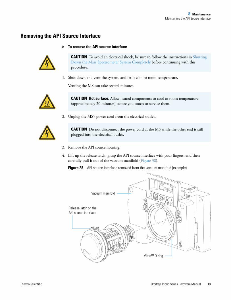
8 MaintenanceMaintaining the API Source Interface
Thermo Scientific Orbitrap Tribrid Series Hardware Manual 73
Removing the API Source Interface
To remove the API source interface
1. Shut down and vent the system, and let it cool to room temperature.
Venting the MS can take several minutes.
2. Unplug the MS’s power cord from the electrical outlet.
3. Remove the API source housing.
4. Lift up the release latch, grasp the API source interface with your fingers, and then carefully pull it out of the vacuum manifold (Figure 38).
Figure 38. API source interface removed from the vacuum manifold (example)
CAUTION To avoid an electrical shock, be sure to follow the instructions in Shutting Down the Mass Spectrometer System Completely before continuing with this procedure.
CAUTION Hot surface. Allow heated components to cool to room temperature (approximately 20 minutes) before you touch or service them.
CAUTION Do not disconnect the power cord at the MS while the other end is still plugged into the electrical outlet.
Release latch on the API source interface
Vacuum manifold
Viton™ O-ring
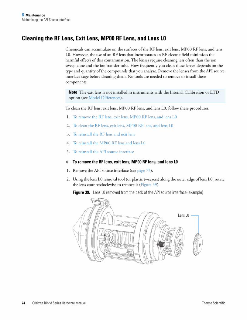
8 MaintenanceMaintaining the API Source Interface
74 Orbitrap Tribrid Series Hardware Manual Thermo Scientific
Cleaning the RF Lens, Exit Lens, MP00 RF Lens, and Lens L0
Chemicals can accumulate on the surfaces of the RF lens, exit lens, MP00 RF lens, and lens L0. However, the use of an RF lens that incorporates an RF electric field minimizes the harmful effects of this contamination. The lenses require cleaning less often than the ion sweep cone and the ion transfer tube. How frequently you clean these lenses depends on the type and quantity of the compounds that you analyze. Remove the lenses from the API source interface cage before cleaning them. No tools are needed to remove or install these components.
To clean the RF lens, exit lens, MP00 RF lens, and lens L0, follow these procedures:
1. To remove the RF lens, exit lens, MP00 RF lens, and lens L0
2. To clean the RF lens, exit lens, MP00 RF lens, and lens L0
3. To reinstall the RF lens and exit lens
4. To reinstall the MP00 RF lens and lens L0
5. To reinstall the API source interface
To remove the RF lens, exit lens, MP00 RF lens, and lens L0
1. Remove the API source interface (see page 73).
2. Using the lens L0 removal tool (or plastic tweezers) along the outer edge of lens L0, rotate the lens counterclockwise to remove it (Figure 39).
Figure 39. Lens L0 removed from the back of the API source interface (example)
Note The exit lens is not installed in instruments with the Internal Calibration or ETD option (see Model Differences).
Lens L0
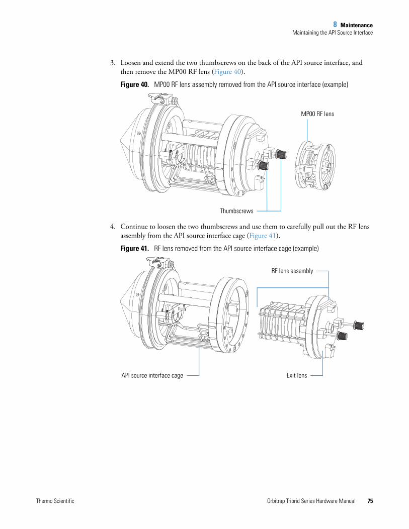
8 MaintenanceMaintaining the API Source Interface
Thermo Scientific Orbitrap Tribrid Series Hardware Manual 75
3. Loosen and extend the two thumbscrews on the back of the API source interface, and then remove the MP00 RF lens (Figure 40).
Figure 40. MP00 RF lens assembly removed from the API source interface (example)
4. Continue to loosen the two thumbscrews and use them to carefully pull out the RF lens assembly from the API source interface cage (Figure 41).
Figure 41. RF lens removed from the API source interface cage (example)
MP00 RF lens
Thumbscrews
Exit lensAPI source interface cage
RF lens assembly
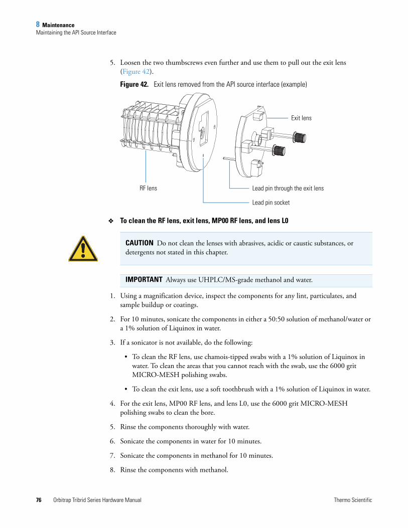
8 MaintenanceMaintaining the API Source Interface
76 Orbitrap Tribrid Series Hardware Manual Thermo Scientific
5. Loosen the two thumbscrews even further and use them to pull out the exit lens (Figure 42).
Figure 42. Exit lens removed from the API source interface (example)
To clean the RF lens, exit lens, MP00 RF lens, and lens L0
1. Using a magnification device, inspect the components for any lint, particulates, and sample buildup or coatings.
2. For 10 minutes, sonicate the components in either a 50:50 solution of methanol/water or a 1% solution of Liquinox in water.
3. If a sonicator is not available, do the following:
• To clean the RF lens, use chamois-tipped swabs with a 1% solution of Liquinox in water. To clean the areas that you cannot reach with the swab, use the 6000 grit MICRO-MESH polishing swabs.
• To clean the exit lens, use a soft toothbrush with a 1% solution of Liquinox in water.
4. For the exit lens, MP00 RF lens, and lens L0, use the 6000 grit MICRO-MESH polishing swabs to clean the bore.
5. Rinse the components thoroughly with water.
6. Sonicate the components in water for 10 minutes.
7. Sonicate the components in methanol for 10 minutes.
8. Rinse the components with methanol.
Exit lens
Lead pin through the exit lensRF lens
Lead pin socket
CAUTION Do not clean the lenses with abrasives, acidic or caustic substances, or detergents not stated in this chapter.
IMPORTANT Always use UHPLC/MS-grade methanol and water.
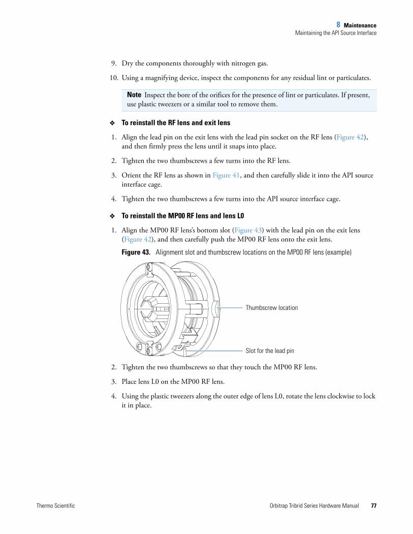
8 MaintenanceMaintaining the API Source Interface
Thermo Scientific Orbitrap Tribrid Series Hardware Manual 77
9. Dry the components thoroughly with nitrogen gas.
10. Using a magnifying device, inspect the components for any residual lint or particulates.
To reinstall the RF lens and exit lens
1. Align the lead pin on the exit lens with the lead pin socket on the RF lens (Figure 42), and then firmly press the lens until it snaps into place.
2. Tighten the two thumbscrews a few turns into the RF lens.
3. Orient the RF lens as shown in Figure 41, and then carefully slide it into the API source interface cage.
4. Tighten the two thumbscrews a few turns into the API source interface cage.
To reinstall the MP00 RF lens and lens L0
1. Align the MP00 RF lens’s bottom slot (Figure 43) with the lead pin on the exit lens (Figure 42), and then carefully push the MP00 RF lens onto the exit lens.
Figure 43. Alignment slot and thumbscrew locations on the MP00 RF lens (example)
2. Tighten the two thumbscrews so that they touch the MP00 RF lens.
3. Place lens L0 on the MP00 RF lens.
4. Using the plastic tweezers along the outer edge of lens L0, rotate the lens clockwise to lock it in place.
Note Inspect the bore of the orifices for the presence of lint or particulates. If present, use plastic tweezers or a similar tool to remove them.
Thumbscrew location
Slot for the lead pin
8 MaintenanceMaintaining the Forepump
78 Orbitrap Tribrid Series Hardware Manual Thermo Scientific
Reinstalling the API Source Interface
To reinstall the API source interface
1. Orient the API source interface with the release latch at the top (Figure 38).
2. Carefully insert the API source interface into the vacuum manifold.
3. Reinstall the API source housing.
4. Start up the system as described in Starting the System after a Complete Shutdown.
Maintaining the ForepumpMaintaining the forepumps requires inspecting, adding, purging, and changing the pump oil. Refer to the manufacturer’s manual for instructions.
Check the forepump oil often. New oil has a translucent, light amber color. During normal operation, oil must always be visible in the oil level sight glass between the MIN and MAX marks. If the oil level is below the MIN mark, add oil. If the oil is cloudy or discolored, purge the oil to decontaminate dissolved solvents. If the pump oil is still discolored, change it. Plan to change the pump oil every 10 000 hours (or about every 12–13 months) of operation.
To access the forepumps under the workbench
1. Place the MS in Off mode, .
2. Place the electronics service switch in the Service Mode (down) position.
3. Turn off the Main Power switch.
4. Lift up the workbench’s front panel to remove it, and set it aside.
5. Carefully move the forepumps forward.
6. Reattach the front panel when you are ready.
CAUTION To minimize the risk of oil contamination in the vacuum system, make sure that the purging ballast is closed when you vent the system to atmosphere.
CAUTION Possible pinch points. Be aware where you place your hands when you remove or attach the workbench’s front panel.
8 MaintenanceMaintaining the Air Filter
Thermo Scientific Orbitrap Tribrid Series Hardware Manual 79
Maintaining the Air FilterClean the air filter located on the right side of the MS every four months, or sooner if it is dirty.
To clean the air filter
1. Remove the air filter as follows:
a. Using the Phillips #2 screwdriver, remove the filter’s four screws.
b. Remove the black metal panel.
c. Carefully pull out the metal-mesh filter.
2. Wash the filter in a solution of soap and water.
3. Rinse the filter with tap water, and then allow it to air dry.
4. Reinstall the air filter and metal panel.
Pumping Down the Mass Spectrometer
To pump down the MS
1. Check that the forepumps’ exhaust tubing connect to the exhaust system and that any valves in the exhaust path are open.
2. Turn on the Main Power switch (Figure 44), wait 15 minutes, and then place the electronics service switch in the Operating Mode (up) position.
When the MS enters operating mode, the restart sequence begins. The Power LED on the front panel turns green, and the Vacuum, Communication, and System LEDs remain off. When the MS startup process is complete, the Vacuum and Communication LEDs are green and the System LED is yellow. The MS is now in standby mode.
IMPORTANT If the MS was turned off for an extended period of time, pump down the vacuum system for at least 15 hours and bakeout the Orbitrap FT chamber for 12 hours during that period.
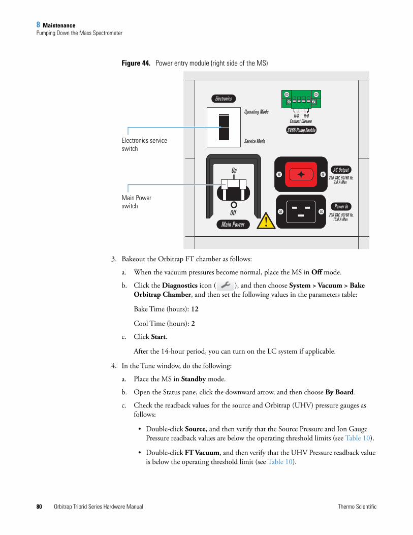
8 MaintenancePumping Down the Mass Spectrometer
80 Orbitrap Tribrid Series Hardware Manual Thermo Scientific
Figure 44. Power entry module (right side of the MS)
3. Bakeout the Orbitrap FT chamber as follows:
a. When the vacuum pressures become normal, place the MS in Off mode.
b. Click the Diagnostics icon ( ), and then choose System > Vacuum > Bake Orbitrap Chamber, and then set the following values in the parameters table:
Bake Time (hours): 12
Cool Time (hours): 2
c. Click Start.
After the 14-hour period, you can turn on the LC system if applicable.
4. In the Tune window, do the following:
a. Place the MS in Standby mode.
b. Open the Status pane, click the downward arrow, and then choose By Board.
c. Check the readback values for the source and Orbitrap (UHV) pressure gauges as follows:
• Double-click Source, and then verify that the Source Pressure and Ion Gauge Pressure readback values are below the operating threshold limits (see Table 10).
• Double-click FT Vacuum, and then verify that the UHV Pressure readback value is below the operating threshold limit (see Table 10).
Electronics service switch
Main Power switch

8 MaintenancePumping Down the Mass Spectrometer
Thermo Scientific Orbitrap Tribrid Series Hardware Manual 81
Normal readback measurements show a green square ( ). If the vacuum pressure values are normal, go to the next section.
Table 10.Threshold limits for the vacuum pressure gauges
Instrument Source pressure (Torr)
Ion gauge pressure (Torr)
UHV pressure (Torr)
Orbitrap Fusion and Orbitrap ID-X
Less than 3.01.5 × 10–4 5 × 10⁻⁸
Orbitrap Fusion Lumos Less than 4.5

8 MaintenancePumping Down the Mass Spectrometer
82 Orbitrap Tribrid Series Hardware Manual Thermo Scientific
Thermo Scientific Orbitrap Tribrid Series Hardware Manual 83
9
Replaceable Parts
The Orbitrap Tribrid Series MS arrives with the following kits and replaceable parts. The exception is the Chemical Kit, which arrives separately as part of the preinstallation kit. Use the provided part numbers when ordering replacement parts.
Contents
• Orbitrap Tribrid Series Chemicals Kit
• Calibration Kit
• MS Setup Kit
• Performance Specification Kit
• Single Mechanical Pump Kit
• Dual Mechanical Pumps Kit
• API Source Interface
• Miscellaneous Parts
Orbitrap Tribrid Series Chemicals KitOrbitrap Fusion Chemicals Kit. . . . . . . . . . . . . . . . . . . . . . . . . . . . . . . . . . 80000-62049
Positive calibration solution (calmix), n-Butylamine, 10 mL (Pierce™ 88323, 2 provided). . . . . . . . . . . . . . . . . . . . . . . . . . HAZMAT-01-00061
Negative calibration solution (calmix), Ultramark 1621, 10 mL (Pierce 88324, 2 provided) . . . . . . . . . . . . . . . . . . . . . . . . . . . HAZMAT-01-00062
Enfuvirtide, 90 mg . . . . . . . . . . . . . . . . . . . . . . . . . . . . . . . . . . . . HAZMAT-01-00083Reserpine standard solution, 100 pg/μL, 1 mL vial
(5 provided) . . . . . . . . . . . . . . . . . . . . . . . . . . . . . . . . . . . . . . HAZMAT-01-00081LCMS Functionality Test Kit . . . . . . . . . . . . . . . . . . . . . . . . . . . . HAZMAT-01-00044
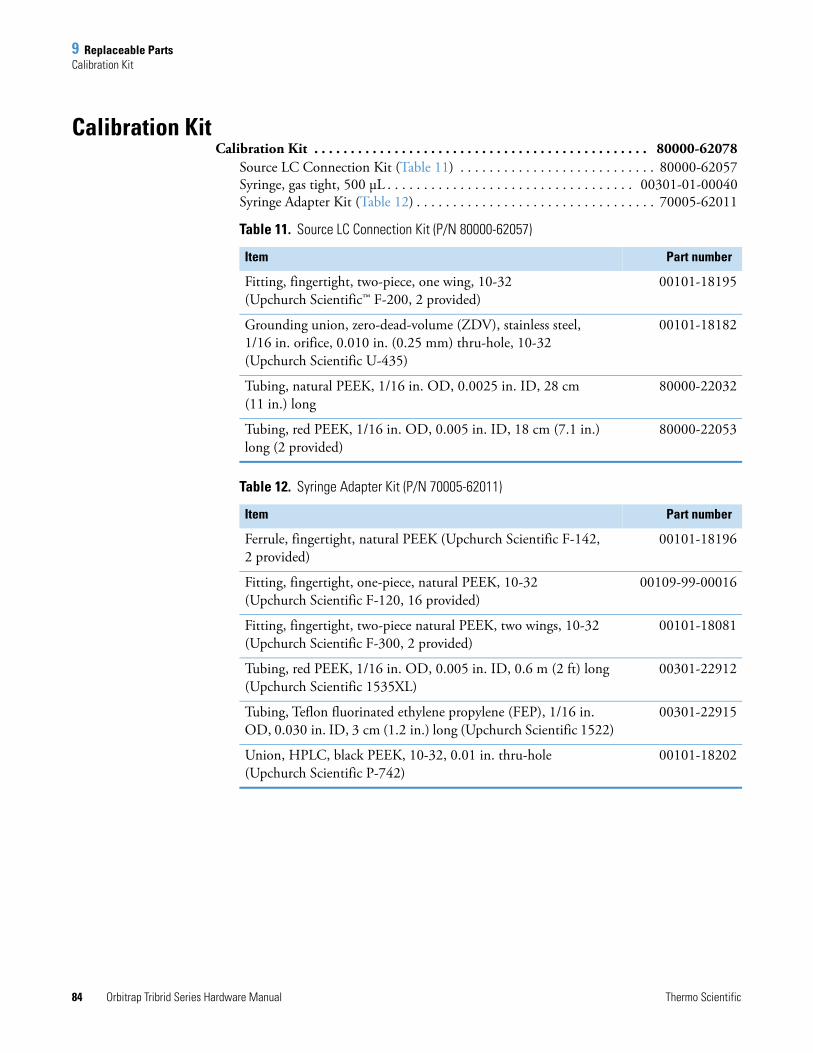
9 Replaceable PartsCalibration Kit
84 Orbitrap Tribrid Series Hardware Manual Thermo Scientific
Calibration KitCalibration Kit . . . . . . . . . . . . . . . . . . . . . . . . . . . . . . . . . . . . . . . . . . . . . . 80000-62078
Source LC Connection Kit (Table 11) . . . . . . . . . . . . . . . . . . . . . . . . . . . 80000-62057Syringe, gas tight, 500 μL . . . . . . . . . . . . . . . . . . . . . . . . . . . . . . . . . . 00301-01-00040Syringe Adapter Kit (Table 12) . . . . . . . . . . . . . . . . . . . . . . . . . . . . . . . . . 70005-62011
Table 11. Source LC Connection Kit (P/N 80000-62057)
Item Part number
Fitting, fingertight, two-piece, one wing, 10-32 (Upchurch Scientific™ F-200, 2 provided)
00101-18195
Grounding union, zero-dead-volume (ZDV), stainless steel, 1/16 in. orifice, 0.010 in. (0.25 mm) thru-hole, 10-32 (Upchurch Scientific U-435)
00101-18182
Tubing, natural PEEK, 1/16 in. OD, 0.0025 in. ID, 28 cm (11 in.) long
80000-22032
Tubing, red PEEK, 1/16 in. OD, 0.005 in. ID, 18 cm (7.1 in.) long (2 provided)
80000-22053
Table 12. Syringe Adapter Kit (P/N 70005-62011)
Item Part number
Ferrule, fingertight, natural PEEK (Upchurch Scientific F-142, 2 provided)
00101-18196
Fitting, fingertight, one-piece, natural PEEK, 10-32 (Upchurch Scientific F-120, 16 provided)
00109-99-00016
Fitting, fingertight, two-piece natural PEEK, two wings, 10-32 (Upchurch Scientific F-300, 2 provided)
00101-18081
Tubing, red PEEK, 1/16 in. OD, 0.005 in. ID, 0.6 m (2 ft) long (Upchurch Scientific 1535XL)
00301-22912
Tubing, Teflon fluorinated ethylene propylene (FEP), 1/16 in. OD, 0.030 in. ID, 3 cm (1.2 in.) long (Upchurch Scientific 1522)
00301-22915
Union, HPLC, black PEEK, 10-32, 0.01 in. thru-hole (Upchurch Scientific P-742)
00101-18202
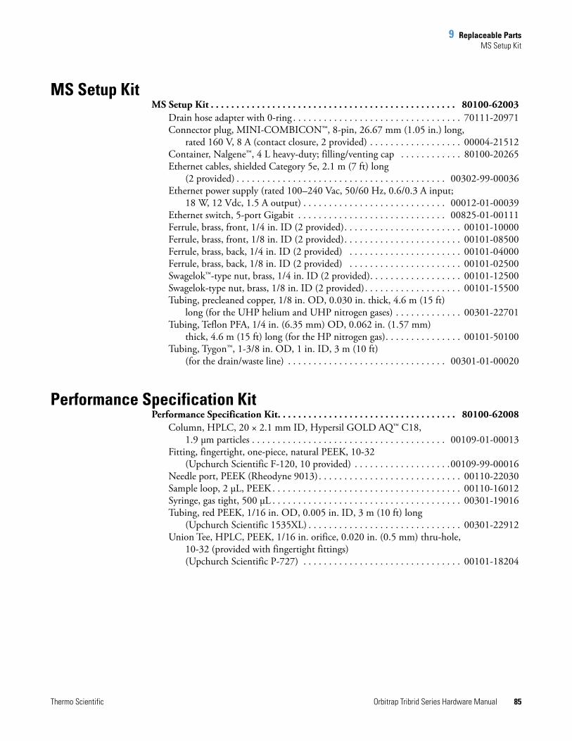
9 Replaceable PartsMS Setup Kit
Thermo Scientific Orbitrap Tribrid Series Hardware Manual 85
MS Setup KitMS Setup Kit . . . . . . . . . . . . . . . . . . . . . . . . . . . . . . . . . . . . . . . . . . . . . . . . 80100-62003
Drain hose adapter with 0-ring . . . . . . . . . . . . . . . . . . . . . . . . . . . . . . . . . 70111-20971Connector plug, MINI-COMBICON™, 8-pin, 26.67 mm (1.05 in.) long,
rated 160 V, 8 A (contact closure, 2 provided) . . . . . . . . . . . . . . . . . . 00004-21512Container, Nalgene™, 4 L heavy-duty; filling/venting cap . . . . . . . . . . . . 80100-20265Ethernet cables, shielded Category 5e, 2.1 m (7 ft) long
(2 provided) . . . . . . . . . . . . . . . . . . . . . . . . . . . . . . . . . . . . . . . . . 00302-99-00036Ethernet power supply (rated 100–240 Vac, 50/60 Hz, 0.6/0.3 A input;
18 W, 12 Vdc, 1.5 A output) . . . . . . . . . . . . . . . . . . . . . . . . . . . . 00012-01-00039Ethernet switch, 5-port Gigabit . . . . . . . . . . . . . . . . . . . . . . . . . . . . . 00825-01-00111Ferrule, brass, front, 1/4 in. ID (2 provided). . . . . . . . . . . . . . . . . . . . . . . 00101-10000Ferrule, brass, front, 1/8 in. ID (2 provided). . . . . . . . . . . . . . . . . . . . . . . 00101-08500Ferrule, brass, back, 1/4 in. ID (2 provided) . . . . . . . . . . . . . . . . . . . . . . 00101-04000Ferrule, brass, back, 1/8 in. ID (2 provided) . . . . . . . . . . . . . . . . . . . . . . 00101-02500Swagelok™-type nut, brass, 1/4 in. ID (2 provided). . . . . . . . . . . . . . . . . . 00101-12500Swagelok-type nut, brass, 1/8 in. ID (2 provided). . . . . . . . . . . . . . . . . . . 00101-15500Tubing, precleaned copper, 1/8 in. OD, 0.030 in. thick, 4.6 m (15 ft)
long (for the UHP helium and UHP nitrogen gases) . . . . . . . . . . . . . 00301-22701Tubing, Teflon PFA, 1/4 in. (6.35 mm) OD, 0.062 in. (1.57 mm)
thick, 4.6 m (15 ft) long (for the HP nitrogen gas). . . . . . . . . . . . . . . 00101-50100Tubing, Tygon™, 1-3/8 in. OD, 1 in. ID, 3 m (10 ft)
(for the drain/waste line) . . . . . . . . . . . . . . . . . . . . . . . . . . . . . . . 00301-01-00020
Performance Specification KitPerformance Specification Kit. . . . . . . . . . . . . . . . . . . . . . . . . . . . . . . . . . . 80100-62008
Column, HPLC, 20 × 2.1 mm ID, Hypersil GOLD AQ™ C18, 1.9 μm particles . . . . . . . . . . . . . . . . . . . . . . . . . . . . . . . . . . . . . . 00109-01-00013
Fitting, fingertight, one-piece, natural PEEK, 10-32 (Upchurch Scientific F-120, 10 provided) . . . . . . . . . . . . . . . . . . .00109-99-00016
Needle port, PEEK (Rheodyne 9013). . . . . . . . . . . . . . . . . . . . . . . . . . . . 00110-22030Sample loop, 2 μL, PEEK . . . . . . . . . . . . . . . . . . . . . . . . . . . . . . . . . . . . . 00110-16012Syringe, gas tight, 500 μL . . . . . . . . . . . . . . . . . . . . . . . . . . . . . . . . . . . . . 00301-19016Tubing, red PEEK, 1/16 in. OD, 0.005 in. ID, 3 m (10 ft) long
(Upchurch Scientific 1535XL) . . . . . . . . . . . . . . . . . . . . . . . . . . . . . . 00301-22912Union Tee, HPLC, PEEK, 1/16 in. orifice, 0.020 in. (0.5 mm) thru-hole,
10-32 (provided with fingertight fittings)(Upchurch Scientific P-727) . . . . . . . . . . . . . . . . . . . . . . . . . . . . . . . 00101-18204
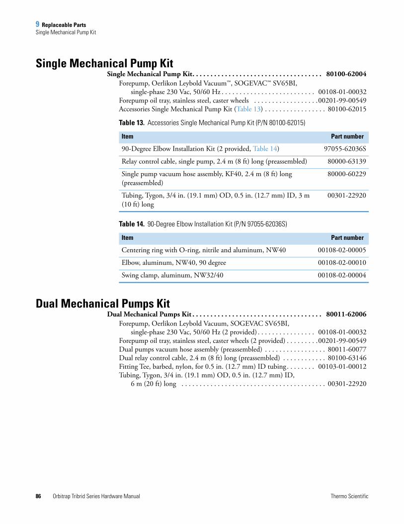
9 Replaceable PartsSingle Mechanical Pump Kit
86 Orbitrap Tribrid Series Hardware Manual Thermo Scientific
Single Mechanical Pump KitSingle Mechanical Pump Kit. . . . . . . . . . . . . . . . . . . . . . . . . . . . . . . . . . . . 80100-62004
Forepump, Oerlikon Leybold Vacuum™, SOGEVAC™ SV65BI, single-phase 230 Vac, 50/60 Hz . . . . . . . . . . . . . . . . . . . . . . . . . . 00108-01-00032
Forepump oil tray, stainless steel, caster wheels . . . . . . . . . . . . . . . . . .00201-99-00549Accessories Single Mechanical Pump Kit (Table 13) . . . . . . . . . . . . . . . . . 80100-62015
Dual Mechanical Pumps KitDual Mechanical Pumps Kit . . . . . . . . . . . . . . . . . . . . . . . . . . . . . . . . . . . . 80011-62006
Forepump, Oerlikon Leybold Vacuum, SOGEVAC SV65BI,single-phase 230 Vac, 50/60 Hz (2 provided) . . . . . . . . . . . . . . . . 00108-01-00032
Forepump oil tray, stainless steel, caster wheels (2 provided) . . . . . . . . .00201-99-00549Dual pumps vacuum hose assembly (preassembled) . . . . . . . . . . . . . . . . . 80011-60077Dual relay control cable, 2.4 m (8 ft) long (preassembled) . . . . . . . . . . . . 80100-63146Fitting Tee, barbed, nylon, for 0.5 in. (12.7 mm) ID tubing. . . . . . . . 00103-01-00012Tubing, Tygon, 3/4 in. (19.1 mm) OD, 0.5 in. (12.7 mm) ID,
6 m (20 ft) long . . . . . . . . . . . . . . . . . . . . . . . . . . . . . . . . . . . . . . . . 00301-22920
Table 13. Accessories Single Mechanical Pump Kit (P/N 80100-62015)
Item Part number
90-Degree Elbow Installation Kit (2 provided, Table 14) 97055-62036S
Relay control cable, single pump, 2.4 m (8 ft) long (preassembled) 80000-63139
Single pump vacuum hose assembly, KF40, 2.4 m (8 ft) long (preassembled)
80000-60229
Tubing, Tygon, 3/4 in. (19.1 mm) OD, 0.5 in. (12.7 mm) ID, 3 m (10 ft) long
00301-22920
Table 14. 90-Degree Elbow Installation Kit (P/N 97055-62036S)
Item Part number
Centering ring with O-ring, nitrile and aluminum, NW40 00108-02-00005
Elbow, aluminum, NW40, 90 degree 00108-02-00010
Swing clamp, aluminum, NW32/40 00108-02-00004
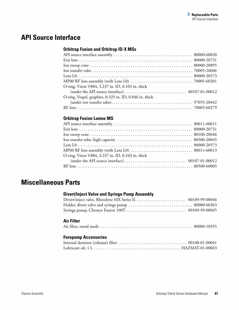
9 Replaceable PartsAPI Source Interface
Thermo Scientific Orbitrap Tribrid Series Hardware Manual 87
API Source Interface
Orbitrap Fusion and Orbitrap ID-X MSsAPI source interface assembly . . . . . . . . . . . . . . . . . . . . . . . . . . . . . . . . . . . . . 80000-60820Exit lens . . . . . . . . . . . . . . . . . . . . . . . . . . . . . . . . . . . . . . . . . . . . . . . . . . . . . 80000-20731Ion sweep cone . . . . . . . . . . . . . . . . . . . . . . . . . . . . . . . . . . . . . . . . . . . . . . . . 80000-20895Ion transfer tube . . . . . . . . . . . . . . . . . . . . . . . . . . . . . . . . . . . . . . . . . . . . . . . 70005-20606Lens L0 . . . . . . . . . . . . . . . . . . . . . . . . . . . . . . . . . . . . . . . . . . . . . . . . . . . . . . 80000-20573MP00 RF lens assembly (with Lens L0) . . . . . . . . . . . . . . . . . . . . . . . . . . . . . 70005-60201O-ring, Viton V884, 3.237 in. ID, 0.103 in. thick
(under the API source interface) . . . . . . . . . . . . . . . . . . . . . . . . . . . . . 00107-01-00012O-ring, Vespel, graphite, 0.325 in. ID, 0.046 in. thick
(under ion transfer tube). . . . . . . . . . . . . . . . . . . . . . . . . . . . . . . . . . . . . . 97055-20442RF lens . . . . . . . . . . . . . . . . . . . . . . . . . . . . . . . . . . . . . . . . . . . . . . . . . . . . . . 70005-60279
Orbitrap Fusion Lumos MSAPI source interface assembly . . . . . . . . . . . . . . . . . . . . . . . . . . . . . . . . . . . . . 80011-60011Exit lens . . . . . . . . . . . . . . . . . . . . . . . . . . . . . . . . . . . . . . . . . . . . . . . . . . . . . 80000-20731Ion sweep cone . . . . . . . . . . . . . . . . . . . . . . . . . . . . . . . . . . . . . . . . . . . . . . . . 80100-20646Ion transfer tube, high capacity . . . . . . . . . . . . . . . . . . . . . . . . . . . . . . . . . . . 80500-20045Lens L0 . . . . . . . . . . . . . . . . . . . . . . . . . . . . . . . . . . . . . . . . . . . . . . . . . . . . . . 80000-20573MP00 RF lens assembly (with Lens L0) . . . . . . . . . . . . . . . . . . . . . . . . . . . . . 80011-60013O-ring, Viton V884, 3.237 in. ID, 0.103 in. thick
(under the API source interface) . . . . . . . . . . . . . . . . . . . . . . . . . . . . . 00107-01-00012RF lens . . . . . . . . . . . . . . . . . . . . . . . . . . . . . . . . . . . . . . . . . . . . . . . . . . . . . . 80500-60005
Miscellaneous Parts
Divert/Inject Valve and Syringe Pump AssemblyDivert/inject valve, Rheodyne MX Series II. . . . . . . . . . . . . . . . . . . . . . . . 00109-99-00046Holder, divert valve and syringe pump . . . . . . . . . . . . . . . . . . . . . . . . . . . . . . 80000-60363Syringe pump, Chemyx Fusion 100T . . . . . . . . . . . . . . . . . . . . . . . . . . . . 00109-99-00045
Air FilterAir filter, metal mesh . . . . . . . . . . . . . . . . . . . . . . . . . . . . . . . . . . . . . . . . . . . . 80000-10355
Forepump AccessoriesInternal demister (exhaust) filter . . . . . . . . . . . . . . . . . . . . . . . . . . . . . . . . 00108-01-00041Lubricant oil, 1 L . . . . . . . . . . . . . . . . . . . . . . . . . . . . . . . . . . . . . . . . HAZMAT-01-00063
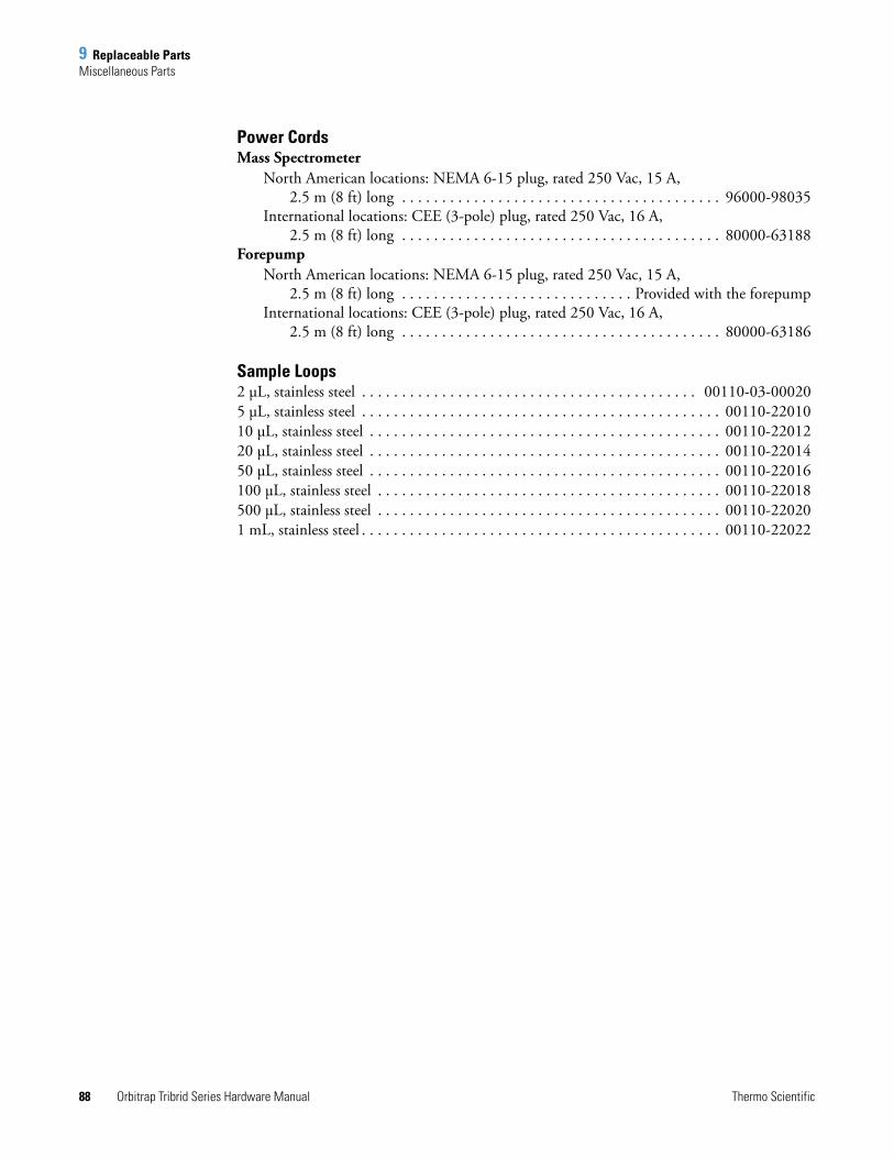
9 Replaceable PartsMiscellaneous Parts
88 Orbitrap Tribrid Series Hardware Manual Thermo Scientific
Power CordsMass Spectrometer
North American locations: NEMA 6-15 plug, rated 250 Vac, 15 A, 2.5 m (8 ft) long . . . . . . . . . . . . . . . . . . . . . . . . . . . . . . . . . . . . . . . . 96000-98035
International locations: CEE (3-pole) plug, rated 250 Vac, 16 A, 2.5 m (8 ft) long . . . . . . . . . . . . . . . . . . . . . . . . . . . . . . . . . . . . . . . . 80000-63188
ForepumpNorth American locations: NEMA 6-15 plug, rated 250 Vac, 15 A,
2.5 m (8 ft) long . . . . . . . . . . . . . . . . . . . . . . . . . . . . . Provided with the forepumpInternational locations: CEE (3-pole) plug, rated 250 Vac, 16 A,
2.5 m (8 ft) long . . . . . . . . . . . . . . . . . . . . . . . . . . . . . . . . . . . . . . . . 80000-63186
Sample Loops2 μL, stainless steel . . . . . . . . . . . . . . . . . . . . . . . . . . . . . . . . . . . . . . . . . . 00110-03-000205 μL, stainless steel . . . . . . . . . . . . . . . . . . . . . . . . . . . . . . . . . . . . . . . . . . . . . 00110-2201010 μL, stainless steel . . . . . . . . . . . . . . . . . . . . . . . . . . . . . . . . . . . . . . . . . . . . 00110-2201220 μL, stainless steel . . . . . . . . . . . . . . . . . . . . . . . . . . . . . . . . . . . . . . . . . . . . 00110-2201450 μL, stainless steel . . . . . . . . . . . . . . . . . . . . . . . . . . . . . . . . . . . . . . . . . . . . 00110-22016100 μL, stainless steel . . . . . . . . . . . . . . . . . . . . . . . . . . . . . . . . . . . . . . . . . . . 00110-22018500 μL, stainless steel . . . . . . . . . . . . . . . . . . . . . . . . . . . . . . . . . . . . . . . . . . . 00110-220201 mL, stainless steel . . . . . . . . . . . . . . . . . . . . . . . . . . . . . . . . . . . . . . . . . . . . . 00110-22022
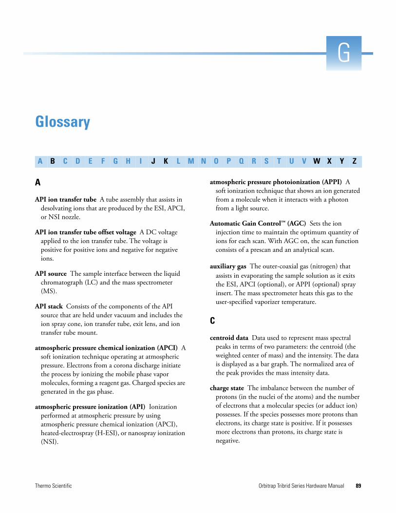
Thermo Scientific Orbitrap Tribrid Series Hardware Manual 89
G
Glossary
A
API ion transfer tube A tube assembly that assists in desolvating ions that are produced by the ESI, APCI, or NSI nozzle.
API ion transfer tube offset voltage A DC voltage applied to the ion transfer tube. The voltage is positive for positive ions and negative for negative ions.
API source The sample interface between the liquid chromatograph (LC) and the mass spectrometer (MS).
API stack Consists of the components of the API source that are held under vacuum and includes the ion spray cone, ion transfer tube, exit lens, and ion transfer tube mount.
atmospheric pressure chemical ionization (APCI) A soft ionization technique operating at atmospheric pressure. Electrons from a corona discharge initiate the process by ionizing the mobile phase vapor molecules, forming a reagent gas. Charged species are generated in the gas phase.
atmospheric pressure ionization (API) Ionization performed at atmospheric pressure by using atmospheric pressure chemical ionization (APCI), heated-electrospray (H-ESI), or nanospray ionization (NSI).
atmospheric pressure photoionization (APPI) A soft ionization technique that shows an ion generated from a molecule when it interacts with a photon from a light source.
Automatic Gain Control™ (AGC) Sets the ion injection time to maintain the optimum quantity of ions for each scan. With AGC on, the scan function consists of a prescan and an analytical scan.
auxiliary gas The outer-coaxial gas (nitrogen) that assists in evaporating the sample solution as it exits the ESI, APCI (optional), or APPI (optional) spray insert. The mass spectrometer heats this gas to the user-specified vaporizer temperature.
C
centroid data Data used to represent mass spectral peaks in terms of two parameters: the centroid (the weighted center of mass) and the intensity. The data is displayed as a bar graph. The normalized area of the peak provides the mass intensity data.
charge state The imbalance between the number of protons (in the nuclei of the atoms) and the number of electrons that a molecular species (or adduct ion) possesses. If the species possesses more protons than electrons, its charge state is positive. If it possesses more electrons than protons, its charge state is negative.
A B C D E F G H I J K L M N O P Q R S T U V W X Y Z
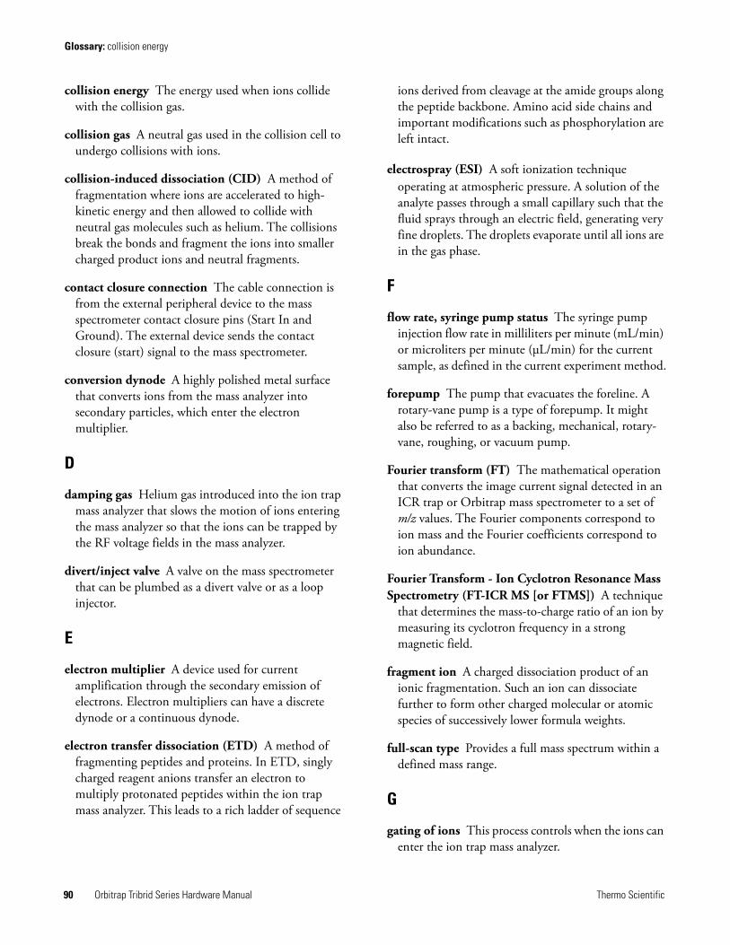
Glossary: collision energy
90 Orbitrap Tribrid Series Hardware Manual Thermo Scientific
collision energy The energy used when ions collide with the collision gas.
collision gas A neutral gas used in the collision cell to undergo collisions with ions.
collision-induced dissociation (CID) A method of fragmentation where ions are accelerated to high-kinetic energy and then allowed to collide with neutral gas molecules such as helium. The collisions break the bonds and fragment the ions into smaller charged product ions and neutral fragments.
contact closure connection The cable connection is from the external peripheral device to the mass spectrometer contact closure pins (Start In and Ground). The external device sends the contact closure (start) signal to the mass spectrometer.
conversion dynode A highly polished metal surface that converts ions from the mass analyzer into secondary particles, which enter the electron multiplier.
D
damping gas Helium gas introduced into the ion trap mass analyzer that slows the motion of ions entering the mass analyzer so that the ions can be trapped by the RF voltage fields in the mass analyzer.
divert/inject valve A valve on the mass spectrometer that can be plumbed as a divert valve or as a loop injector.
E
electron multiplier A device used for current amplification through the secondary emission of electrons. Electron multipliers can have a discrete dynode or a continuous dynode.
electron transfer dissociation (ETD) A method of fragmenting peptides and proteins. In ETD, singly charged reagent anions transfer an electron to multiply protonated peptides within the ion trap mass analyzer. This leads to a rich ladder of sequence
ions derived from cleavage at the amide groups along the peptide backbone. Amino acid side chains and important modifications such as phosphorylation are left intact.
electrospray (ESI) A soft ionization technique operating at atmospheric pressure. A solution of the analyte passes through a small capillary such that the fluid sprays through an electric field, generating very fine droplets. The droplets evaporate until all ions are in the gas phase.
F
flow rate, syringe pump status The syringe pump injection flow rate in milliliters per minute (mL/min) or microliters per minute (μL/min) for the current sample, as defined in the current experiment method.
forepump The pump that evacuates the foreline. A rotary-vane pump is a type of forepump. It might also be referred to as a backing, mechanical, rotary-vane, roughing, or vacuum pump.
Fourier transform (FT) The mathematical operation that converts the image current signal detected in an ICR trap or Orbitrap mass spectrometer to a set of m/z values. The Fourier components correspond to ion mass and the Fourier coefficients correspond to ion abundance.
Fourier Transform - Ion Cyclotron Resonance Mass Spectrometry (FT-ICR MS [or FTMS]) A technique
that determines the mass-to-charge ratio of an ion by measuring its cyclotron frequency in a strong magnetic field.
fragment ion A charged dissociation product of an ionic fragmentation. Such an ion can dissociate further to form other charged molecular or atomic species of successively lower formula weights.
full-scan type Provides a full mass spectrum within a defined mass range.
G
gating of ions This process controls when the ions can enter the ion trap mass analyzer.
Glossary: heated-electrospray (H-ESI)
Thermo Scientific Orbitrap Tribrid Series Hardware Manual 91
H
heated-electrospray (H-ESI) Converts ions in solution into ions in the gas phase by using electrospray (ESI) in combination with heated auxiliary gas.
higher energy collision-induced dissociation (HCD) Collision-induced dissociation that occurs in
the ion-routing multipole (IRM). The IRM consists of a straight multipole mounted inside a collision gas-filled tube. A voltage offset between the C-trap and IRM accelerates parent ions into the collision gas inside the IRM, which causes the ions to fragment into product ions. The product ions are then sent to the ion trap or the Orbitrap mass analyzer for mass analysis. HCD produces triple quadrupole-like product ion mass spectra.
I
image current detection The detection of ion motion by the charge (current) induced on one or more capacitive plates (outer electrodes).
ion detection system A high sensitivity, off-axis system for detecting ions. It produces a high signal-to-noise ratio (S/N) and allows for switching of the voltage polarity between positive ion and negative ion modes of operation. The ion detection system includes two ±12 kVdc conversion dynodes and a discrete dynode electron multiplier.
ion isolation A step in the quadrupole Q1 or linear ion trap mass analysis where the mass analyzer ejects all ions except for the ions of interest.
ion isolation waveform voltage A waveform applied to the linear ion trap that ejects all ions except the SIM ion or precursor ion.
ion optics Focuses and transmits ions from the API source to the mass analyzer.
ion polarity mode The mass spectrometer can operate in either of two ion polarity modes: positive or negative.
ion sweep cone A removable cone-shaped metal cover that fits on top of the API ion transfer tube and acts as a physical barrier to protect the entrance of the tube.
ion-routing multipole The collision cell where higher energy collision-induced dissociation (HCD) takes place.
L
lens A metal disk with a circular hole in the center that allows the ion beam to pass.
M
make-up gas The gas associated with the optional EASY-IC or EASY-ETD ion source assembly that flows from the mass flow controller to the reagent distribution assembly.
mass analysis A process that produces a mixture of ionic species that is then separated according to the mass-to-charge ratios (m/z) of the ions to produce a mass spectrum.
mass analyzer A device that determines the mass-to-charge ratios (m/z) of ions by one of a variety of techniques.
mass analyzer DC offset voltage A DC voltage that is applied to the mass analyzer electrodes to help draw ions in from the ion optics. This voltage defines the translational kinetic energy of the ions as they enter the mass analyzer. For the mass detector, the mass analyzer DC offset voltage is –10 Vdc for positive ions and +10 Vdc for negative ions.
mass spectrometer An instrument that ionizes sample molecules and then measures and analyses the ions according to their mass-to-charge ratio (m/z). The resulting mass spectrum is a characteristic pattern for the identification of a molecule.
mass spectrum A graphical representation (plot) of measured ion abundance versus mass-to-charge ratio. The mass spectrum is a characteristic pattern for the identification of a molecule and is helpful in determining the chemical composition of a sample.
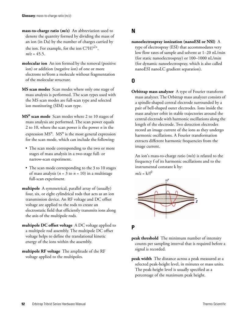
Glossary: mass-to-charge ratio (m/z)
92 Orbitrap Tribrid Series Hardware Manual Thermo Scientific
mass-to-charge ratio (m/z) An abbreviation used to denote the quantity formed by dividing the mass of an ion (in Da) by the number of charges carried by the ion. For example, for the ion C7H72+, m/z = 45.5.
molecular ion An ion formed by the removal (positive ion) or addition (negative ion) of one or more electrons to/from a molecule without fragmentation of the molecular structure.
MS scan modes Scan modes where only one stage of mass analysis is performed. The scan types used with the MS scan modes are full-scan type and selected ion monitoring (SIM) scan type.
MSn scan mode Scan modes where 2 to 10 stages of mass analysis are performed. The scan power equals 2 to 10, where the scan power is the power n in the expression MSn. MSn is the most general expression for the scan mode, which can include the following:
• The scan mode corresponding to the two or more stages of mass analysis in a two-stage full- or narrow-scan experiment.
• The scan mode corresponding to the 3 to 10 stages of mass analysis (n = 3 to n = 10) in a multistage full-scan experiment.
multipole A symmetrical, parallel array of (usually) four, six, or eight cylindrical rods that acts as an ion transmission device. An RF voltage and DC offset voltage are applied to the rods to create an electrostatic field that efficiently transmits ions along the axis of the multipole rods.
multipole DC offset voltage A DC voltage applied to a multipole rod assembly. The multipole DC offset voltage helps to define the translational kinetic energy of the ions within the assembly.
multipole RF voltage The amplitude of the RF voltage applied to the multipoles.
N
nanoelectrospray ionization (nanoESI or NSI) A type of electrospray (ESI) that accommodates very low flow rates of sample and solvent at 1–20 nL/min (for static nanoelectrospray) or 100–1000 nL/min (for dynamic nanoelectrospray, which is also called nanoESI nanoLC gradient separation).
O
Orbitrap mass analyzer A type of Fourier transform mass analyzer. The Orbitrap mass analyzer consists of a spindle-shaped central electrode surrounded by a pair of bell-shaped outer electrodes. Ions inside the mass analyzer orbit in stable trajectories around the central electrode with harmonic oscillations along the length of the electrode. Two detection electrodes record an image current of the ions as they undergo harmonic oscillations. A Fourier transformation extracts different harmonic frequencies from the image current.
An ion's mass-to-charge ratio (m/z) is related to the frequency f of its harmonic oscillations and to the instrumental constant k by: m/z = k/f2
P
peak threshold The minimum number of intensity counts per sampling interval that is required before a signal is recorded.
peak width The distance across a peak measured at a selected peak-height level, in minutes or mass units. The peak-height level is usually specified as a percentage of the maximum peak height.
Glossary: peak width at half height
Thermo Scientific Orbitrap Tribrid Series Hardware Manual 93
peak width at half height The full width of a peak at half its maximum height, sometimes abbreviated FWHM.
precursor ion An electrically charged molecular species that can dissociate to form fragments. The fragments can be electrically charged or neutral species. A precursor ion can be a molecular ion or an electrically charged fragment of a molecular ion.
precursor mass The mass-to-charge ratio of a precursor ion. The location of the center of a target precursor-ion peak in mass-to-charge ratio (m/z) units.
product ion An electrically charged fragment of an isolated precursor ion.
product mass The mass-to-charge ratio of a product ion. The location of the center of a target production peak in mass-to-charge ratio (m/z) units.
profile data Data representing mass spectral peaks as point-to-point plots, with each point having an associated intensity value.
Q
qualitative analysis Chemical analysis designed to determine the identity of the components of a substance.
quantitative analysis Chemical analysis designed to determine the quantity or concentration of a specific substance in a sample.
R
reagent carrier gas Ultra-high-purity nitrogen gas used to transfer the reagent to the reagent ion source that is regulated by the backpressure regulator.
retention time (RT) The time after injection at which a compound elutes. The total time that the compound is retained on the chromatograph column.
RF lens A multipole rod assembly that is operated with only radio frequency (RF) voltage on the rods. In this type of device, virtually all ions have stable trajectories and pass through the assembly.
RF voltage (linear ion trap) An AC voltage of constant frequency and variable amplitude that is applied to the quadrupole rods of a linear ion trap mass analyzer or to the rods of a multipole. Because the frequency of this AC voltage is in the radio frequency (RF) range, it is referred to as RF voltage.
S
scan Comprised of one or more microscans. Each microscan is one mass analysis (ion injection and storage/scan-out of ions) followed by ion detection. After the microscans are summed, the scan data is sent to the data system for display, storage, or both. The process of ramping the amplitude of the RF and DC voltages on the multipole rods in the mass analyzer to transmit ions from the lowest mass to the highest mass of a specified scan range.
scan mode and scan type combinations A function that coordinates the three processes in the MS detector: ionization, mass analysis, and ion detection. You can combine the various scan modes and scan types to perform a wide variety of experiments.
scan power The scan power n in MSn, which expresses the number of stages of mass analysis. For example, a scan power of n = 1 corresponds to an MS1 (or MS) scan with one stage of mass analysis. A scan power of n = 2 corresponds to an MS2 (or MS/MS) scan with two stages of mass analysis. A scan power of n = 3 corresponds to an MS3 scan with three stages of mass analysis, and so on.
selected ion monitoring (SIM) scan type A scan type where the mass spectrometer acquires and records ion current following the isolation of a range of mass-to-charge ratio values.
sheath gas The inner coaxial gas (nitrogen), which is used in the API source to help nebulize the sample solution into a fine mist as the sample solution exits the ESI or APCI nozzle.
Glossary: signal-to-noise ratio (S/N)
94 Orbitrap Tribrid Series Hardware Manual Thermo Scientific
signal-to-noise ratio (S/N) The ratio of the signal height (S) to the noise height (N). The signal height is the baseline corrected peak height. The noise height is the peak-to-peak height of the baseline noise.
sweep gas Nitrogen gas that flows out from the gap between the sweep cone and the ion transfer tube into the API source. Sweep gas aids in solvent declustering and adduct reduction.
syringe pump A device that delivers a solution from a syringe at a specified rate.
T
turbomolecular pump A vacuum pump that provides a high vacuum for the mass spectrometer and detector system.
U
ultraviolet photodissociation (UVPD) A method of fragmentation based on photon absorption by a precursor molecule. Photon absorption causes the molecule to undergo an electronic transition to an excited state followed by subsequent dissociation to fragment species. UVPD produces abundant fragments and is applicable to peptides, proteins, and many other compound classes.
V
vacuum manifold A thick-walled, aluminum chamber, with various electrical feedthroughs and gas inlets, which encloses the API stack, ion optics, mass analyzers, and ion detection system.
vacuum system Components associated with lowering the pressure within the mass spectrometer. A vacuum system includes the vacuum manifold, pumps, pressure gauges, and associated electronics.
Thermo Scientific Orbitrap Tribrid Series Hardware Manual 95
I
Numerics1M option, license required xv, 13
Aactive beam guide, MP0 31air leaks
checking 58fixing 59
API cone seal 71API gas valves, description 19API gases
See gasesAPI modes 23API source
description 23housing, cleaning 67interface assembly 24
API source interfacedescription 24ion transfer tube 24reinstalling 78removing 73replaceable parts 87
autosampler, starting up 51auxiliary gas, description 19
Bbake-out, Orbitrap chamber 80
Ccalibration parameters, resetting to default values 52cleaning procedures
exit lens 76lens L0 76MP00 RF lens 76RF lens 76syringe 60
collision pressure vacuum gauge 21communication connectors 8communication LED, description 6compliance
FCC ivregulatory iii
cone seal, API 71contact closure cable control, connecting with MS application 9
contact closure interface 8contacting us xviiicontamination, preventing 65, 69controls and indicators 6convection gauge, description 21
See also vacuum system, gaugesconversion dynode, description 42cooling fans, description 10customer responsibility 63
Ddaily tasks 57damping (helium) gas 41data system, starting up 50data types 14directives
regulatory iiiWEEE v
divert/inject valve 44documentation
accessing xiiidual-split gate lens
See split gate lens, dual
Eelectromagnetic compatibility iiielectronic assemblies 5
Index

96 Orbitrap Tribrid Series Hardware Manual Thermo Scientific
Index: F
electronics service switchdescription 7location 7
emergency shutdown xvi, 47exit lens
cleaning 76description 25reinstalling 77removing 74
Ffans
description 10filter, cleaning 79
FCC compliance ivfigures, list of xiflushing the inlet components 60forepump
control connector, MS 7description 21oil purging 61
functional block diagramsLC/MS system 5vacuum system 16
Ggases
helium, description 19internal schematic drawing 17nitrogen, description 19supply levels, checking 59
gate lensSee split gate lens, dual
gloves, part numbers 67ground, system 30
Hhelium gas
inlet assembly, description 19pressure value 19pressure, checking 59
Iinlet components, flushing 60inlet gases hardware, description 18ion gauge, description 21ion isolation waveform voltage, description 40ion optics
C-trap 32DC offset voltages 34
description 29ion-routing multipole 33MP0 31MP00 RF lens, cleaning 76MP00, description 30MP1 32MP3 33schematic 29
ion polarity modes 14ion pressure vacuum gauge 21ion sweep cone
cleaning 72description 24figure of 69gas inlet location 71removing 69
ion transfer tubecleaning 71description 24drawing of 71installing 71removal tools 70removing 69
ion trap, lineardescription 39scan rates and peak widths 13
ionization technique, definition 4ion-routing multipole 33
Kkits
Calibration 84Dual Mechanical Pump 86MS Setup 85Orbitrap Fusion Chemicals 83Performance Specification 85Single Mechanical Pump 86
LLC/MS analysis, description 3LEDs 6lenses
dual-split gate 35L0
cleaning 76description 30removing 74
L2, description 34TK1 and TK2 31transfer, TL1 33
license, optional feature xv
Thermo Scientific Orbitrap Tribrid Series Hardware Manual 97
Index: M
line power, specification 7linear ion trap
See ion trap, linearliquid chromatograph
solvent flow, turning off 48, 69starting up 50
loop injection 45
Mmain power switch, description 7maintenance
API source housing, cleaning 67fan filter, cleaning 79forepump oil, purging 61schedule 64tools and supplies 65
mass analysissingle-stage (qualitative) 11two-stage 12workflow chart 28
mass analyzersdescription 34helium damping gas 41linear ion trap operation 41mass filtering, description 36Orbitrap operation 36quadrupole Q1 operation 34RF and DC fields 35
mass range, modes and ranges 13mass spectrometer
emergency shutdown xvifunctional block diagram 5functional description 15gas inlet ports, locations 18on/off status for components, voltages, and
gas flows 54photos 1polarity modes 14power panel 7resetting 52scan types 11shutting down 48shutting down completely xviiStandby mode 48starting up 50turning on 48vacuum manifold 20vacuum system 15
metal needle insert for H-ESI spray insert 64MP00 RF lens
cleaning 76removing 74
MS/MS, description 12MS2 scan type 12MSn scan type 12
Nnitrogen gases
inlets assembly, description 19pressure 19pressure, checking 59
normal scan rate 12
Oon/off status for MS components 54optional features
UVPD, Orbitrap Fusion Lumos xviOrbitrap mass analyzer
cell schematic 36ion detection method 38measuring principle 38
O-ringsAPI source interface, under 73ion transfer tube, under 71
Pparts
See replaceable partsPCBs 5power
entry module 7LED description 6specifications 7
power cord xviipower switch, location 7precursor ions 12pressure gauges, note about 51pressures levels, checking 58pressures, vacuum manifold regions 20procedures
Orbitrap chamber, bake-out 80vacuum, pumping down 79
product ions 12pump down time 51
QQ1 mass analyzer, description 34
98 Orbitrap Tribrid Series Hardware Manual Thermo Scientific
Index: R
Rrapid scan rate 12readback values, vacuum gauges 21regulatory compliance iiirelay switch circuit 9replaceable parts 83reset button 8resonance ejection RF voltage 41resonance excitation RF voltage 40RF lens
cleaning 76description 25reinstalling 77removing 74
Ssafety precautions xvisafety standards iiisample transfer line, flushing 60sample tube, flushing 60scan
definition 4LED description 6power 11rates 12
scan types, description 11sheath gas, description 19shutdown
emergency 47mass spectrometer 48
solvent waste container, emptying 61source pressure vacuum gauge 21split gate lens, dual, description 35spray cone, cleaning 71spray insert, cleaning 60Standby mode 48sweep cone
See ion sweep conesweep gas, description 19switches, MS 7symbols, meaning xvsyringe
adapter assembly, drawing 44cleaning 60priming 43
syringe pumpdefault flow rate 43description 43
system ground 30
system LED, description 6system startup 50
TThermo Fisher Scientific website, user documents xivtranslational kinetic energy (TKE) 34trip hazard xviTune, opening 48turbo scan rate 12turbomolecular pumps, description 21
UUHV (Orbitrap) pressure vacuum gauge, description 21ultraviolet photodissociation (UVPD) xviUSB port, pin-out description 10
Vvacuum LED
description 6note about pressure 51
vacuum manifolddescription 20pressures 20vacuum regions 20
vacuum pressure levels, checking 58vacuum pumps
See turbomolecular pumpsvacuum system
description 15functional block diagram 16gauges
collision pressure 21convection 21ion pressure 21Orbitrap (UHV) pressure 21source pressure 21
pressure levels, checking 58vent prevent ball, description 25vent valve, description 20viewing documents xivvoltages
line power specifications 7resonance excitation RF voltage 40
WWEEE directive vworkbench, removing the front panel 78workflow chart, mass analysis 28

Thermo Scientific Orbitrap Tribrid Series Hardware Manual 99
Index: Z
Zzoom scan rate 12