Embed Size (px)
Citation preview
26 ORBIT Vol .27 No.2 2007
BACK TO BASICS
Electrostatic Discharge on a Large Steam Turbine Generator
[Editor’s Note: The first portion of this article is extracted verbatim from a Feburary 2001 ORBIT article by Mark Snyder. It is reprinted here in its entirety to provide a review for our readers and the necessary background for the attendant case history.]
Electrical or mechanical characteristics can induce an electrical potential (voltage) on the
rotors of some rotating machines. If this voltage is not managed, or if the voltage mitigation system (often a shaft-grounding brush) fails to operate properly through lack of maintenance, the voltage seeks an alternate path to ground. That path will be the metal component—typically a bearing or seal—closest to the shaft. The electric arcing to that component as this voltage is discharged is termed electrostatic discharge. Arcing erodes metal surfaces and opens the tight clearances that these components depend upon for proper operation. If undetected, electrostatic discharge will gradually destroy the bearing or seal, change the rotor dynamics of the machine, and may ulti-mately result in damage to the shaft that requires expensive rework.
Properly maintaining and inspecting the voltage mitigation system and monitoring the rotor dynamics of the machine with a Bently Nevada* machinery condition monitoring system can help avoid this problem.
Sherief Mekawey | Bently Nevada Machinery Diagnostics Engineer | GE Energy, United Arab Emirates | [email protected]
Mark Snyder | Bently Nevada Sales Engineer | GE Energy | [email protected]
Vol .27 No.2 2007 ORBIT 27
BACK TO BASICS
Fluid-Film Bearing Machines
In an operating steam turbine generator (STG), there are
at least three possible sources of voltage between the
shaft and ground:
1. Electromagnetic loop voltage due to asymmetries
in the generator magnetic paths may create an
electric potential between opposite ends of the
generator shaft.
2. Static charges may build up from droplets of water
being thrown off blades in wet stages of the turbine.
3. A capacitive voltage due to a ripple on the DC field
voltage may result in a voltage from shaft to ground.
Manufacturers take these voltages into account when
they design their machines. The bearing at one end
of a generator is normally insulated to create an open
circuit and prevent electromagnetic loop voltage (this is
why special care must be taken to ensure the insulating
properties are maintained whenever instrumentation
is installed in insulated bearings). Voltages between the
shaft and ground, due to a static charge or DC voltage
ripple, can be mitigated by the installation of grounding
brushes that ride on the shaft near the uninsulated
generator bearing. The brushes keep the shaft-to-
ground voltage at a safe level by bleeding off current
and causing the weak source voltage to decay.
Rolling-Element Bearing Machines
Industry observers suspect that similar mechanisms
are behind a rise in rolling-element bearing failures in
motors controlled by adjustable-speed drives [1]. These
drives simulate three-phase power by creating a series
of voltage pulses that only approximate the smooth
sinusoidal waveform of each phase.
Since the roughness of the “pulse width modulated”
waveform prevents them from adding vectorially to
zero at every given instant, a “common mode voltage”
relative to ground is created. This common mode volt-
age can generate bearing currents in at least
three possible ways:
1. The air gap between rotor and stator acts like a
capacitor that periodically discharges when bearing
components contact. This is believed to be the major
cause of bearing damage.
2. Another phenomenon causes current to flow when
the effective bearing impedance is very low, and the
bearings become the path to ground for parasitic
winding capacitances.
3. An inductive effect causes a current to circulate
through the bearings, shaft, and stator enclosure
when the impedance of this circuit is low. Mitigation
techniques for these situations either block bearing
currents or provide a low-impedance path to
ground. These techniques include shaft grounding
brushes, bearing insulation, ceramic rolling ele-
ments or conductive grease, a Faraday shield, and
dual-bridge inverters that balance the excitation of
the motor.
Failure Mechanisms
Occasionally, insulation or grounding brushes wear
out or become ineffective, resulting in a large current
flow through the bearings. In fluid-film bearings, this
can lead to electrostatic discharge through the oil film,
resulting in the melting of a tiny area of the babbitt
metal. Continued discharges over a period of time can
lead to pitting erosion, visible as a frosted appearance
of the bearing surface, and ultimately a wiped bearing.
If the problem goes undetected long enough, the
shaft surface at the bearing may become pitted to the
extent that surface repair is required. This results in a
significant machine outage to remove and repair the
shaft. In some cases, the shaft also requires degaussing
to remove a high level of residual magnetism.
A similar pitting occurs in rolling element bearings. In
the early stages, the bearing race exhibits a satiny finish
that is evenly distributed. In advanced stages, evenly
spaced deep flutings appear on the outer bearing race.
The fluting is especially distinct when the motor runs at
a constant speed.
28 ORBIT Vol .27 No.2 2007
BACK TO BASICS
Detection
In fluid-film bearings, electrostatic discharge results in
erosion of the bearing and is observable by changes
in the bearing clearance. For machines instrumented
with proximity probes, this can be monitored via the
probe gap voltages; as the bearing clearance opens,
gap voltage will change. Therefore, the following are
recommended practices for monitoring:
• Enable gap alarming on your monitoring system.
This is available on numerous Bently Nevada
monitor modules including 3300/16, 3300/61,
and selected 3500 monitors.
• Regularly review shaft centerline plots and gap
voltage trends using diagnostic and trending tools
such as System 1* software.
A June 1995 ORBIT article [2] provides additional infor-
mation about trending gap voltage and using average
shaft centerline plots.
Some machines have voltage and current measuring
instrumentation in the grounding brush circuits that
will alarm on a high level of either parameter, and this
instrumentation is typically provided by the Original
Equipment Manufacturer (OEM) with the machine’s
control system. Both the voltage mitigation system
and its associated instrumentation should be
checked regularly.
For rolling element bearings, seismic transducers
can be used to trend bearing vibration levels. In the
advanced stages of pitting on the outer race, higher
vibration levels can be detected. However, electrostatic
discharge can be difficult to differentiate from other
rolling element bearing problems based solely on
examination of the vibration signals. Typically, visual
inspection of the bearing is required after failure to
positively confirm the root cause.
Historical Perspectives
One of the earliest complete references to this specific
malfunction was an ASME paper [3] by two General
Electric engineers: J.M. Gruber, and E.F. Hansen. Gruber
and Hansen dealt primarily with large turbine generator
sets, and they addressed the destructive effects of shaft
voltages upon bearings.
Categorically, they identified five distinct types of
shaft voltages:
1. The electromagnetic or 60-cycle ac voltage.
2. The ground detector 120-cycle ac voltage.
3. The ignitron excitation voltage.
4. The high-frequency exciter ripple voltage.
5. The electrostatic dc voltage.
In their review of these categories they went into consid-
erable detail on electrostatic voltage where they stated:
The electrostatic shaft voltage has been found to have
several reasonably well-pronounced characteristics as
follows:
• The voltage between shaft and bed plate is direct
current. This means that the polarity does not
reverse periodically.
• The magnitude is not usually constant and in some
cases falls repeatedly to low values after which it
climbs back up to higher values. This means that the
voltage contains both a-c and d-c components even
though the polarity does not reverse.
• The maximum magnitude observed by oscilloscope
was about 250 volts peak.
• The rate of rise of shaft voltage was often in the range
of 200 volts per 1/60 sec. or 12,000 volts per second.
• The voltage decay when falling to zero is less than
0.1 millisecond.

Vol .27 No.2 2007 ORBIT 29
BACK TO BASICS
• The minimum magnitude observed was a few
tenths of a volt.
• Typical magnitudes were between 30 and 100
volts peak value.
• The shaft polarity was positive on many turbines
and negative on fewer turbines.
• The potential at any instant is essentially the same
anywhere along the turbine or generator shaft. The
shaft voltage appears between shaft and bedplate,
which is grounded.
• The maximum current observed in a resistance
circuit connected between shaft and ground, regard-
less of how small the magnitude of resistance, was
approximately 1 milliamp.
Sound engineering conclusions are timeless. This
technical summary by Gruber and Hansen is as
applicable now as it was in 1959. Certainly this list could
be modified to reflect some different measurements,
or different machines, but the fundamental concepts,
descriptions, and characterizations of the phenomena
are still the same. It is comforting to note that physical
principles remain constant, and that our understanding
of many of these physical principles has a tendency to
grow with improved technology, measurements, and
communication.
Case History
A 340 MW Steam Turbine Generator (Figure 1) tripped
twice within two weeks due to intermittent high vibra-
tion on the generator outboard bearing (bearing 6).
Unfortunately, there was no online vibration monitoring
system to provide data that would have enabled
straightforward diagnosis and identification of root
cause. As such, investigation done by mechanical
and instrument teams after the trips did not yield any
evidence of a problem, and the machine was restarted
with the caveat from plant management that vibration
data be obtained to further investigate the problem. The
plant enlisted the services of one of GE’s Bently Nevada
machinery diagnostic engineers to collect and interpret
this data using an ADRE* system.
HP/IP Turbine LP Turbine Generator Exciter
1VD 1HD
BRG 1
45º 45º
2VD 2HD
BRG 2
45º 45º
3VD 3HD
BRG 3
45º 45º
4VD 4HD
BRG 4
45º 45º
5VD 5HD
BRG 5
45º 45º
6VD 6HD
BRG 6
45º 45º
CCWrotation
Figure 1 - Machine train diagram.
30 ORBIT Vol .27 No.2 2007
BACK TO BASICS
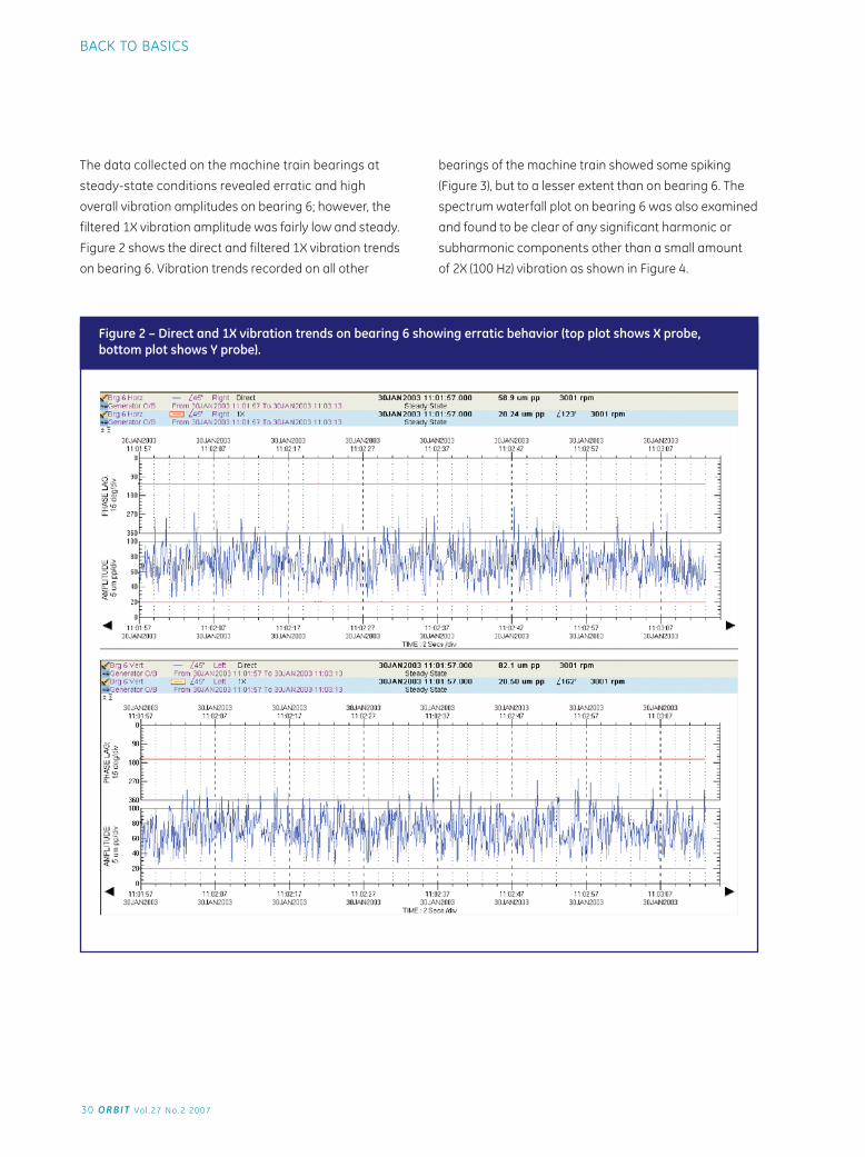
The data collected on the machine train bearings at
steady-state conditions revealed erratic and high
overall vibration amplitudes on bearing 6; however, the
filtered 1X vibration amplitude was fairly low and steady.
Figure 2 shows the direct and filtered 1X vibration trends
on bearing 6. Vibration trends recorded on all other
bearings of the machine train showed some spiking
(Figure 3), but to a lesser extent than on bearing 6. The
spectrum waterfall plot on bearing 6 was also examined
and found to be clear of any significant harmonic or
subharmonic components other than a small amount
of 2X (100 Hz) vibration as shown in Figure 4.
Figure 2 – Direct and 1X vibration trends on bearing 6 showing erratic behavior (top plot shows X probe, bottom plot shows Y probe).
Vol .27 No.2 2007 ORBIT 31
BACK TO BASICS
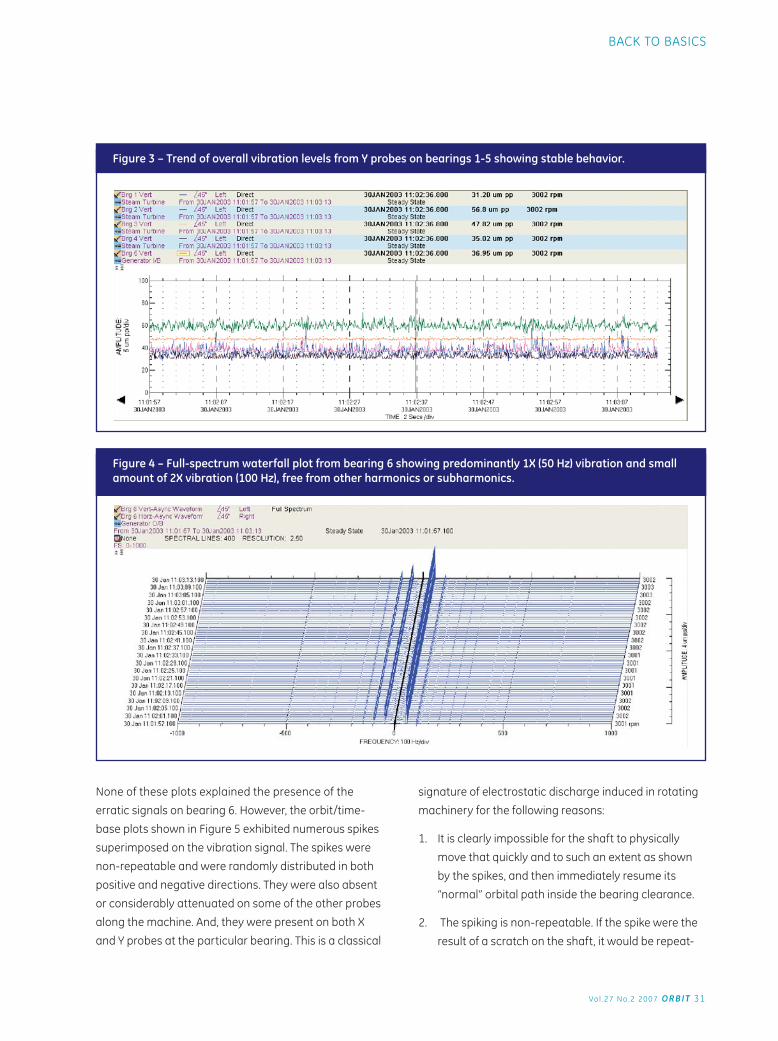
Figure 3 – Trend of overall vibration levels from Y probes on bearings 1-5 showing stable behavior.
Figure 4 – Full-spectrum waterfall plot from bearing 6 showing predominantly 1X (50 Hz) vibration and small amount of 2X vibration (100 Hz), free from other harmonics or subharmonics.
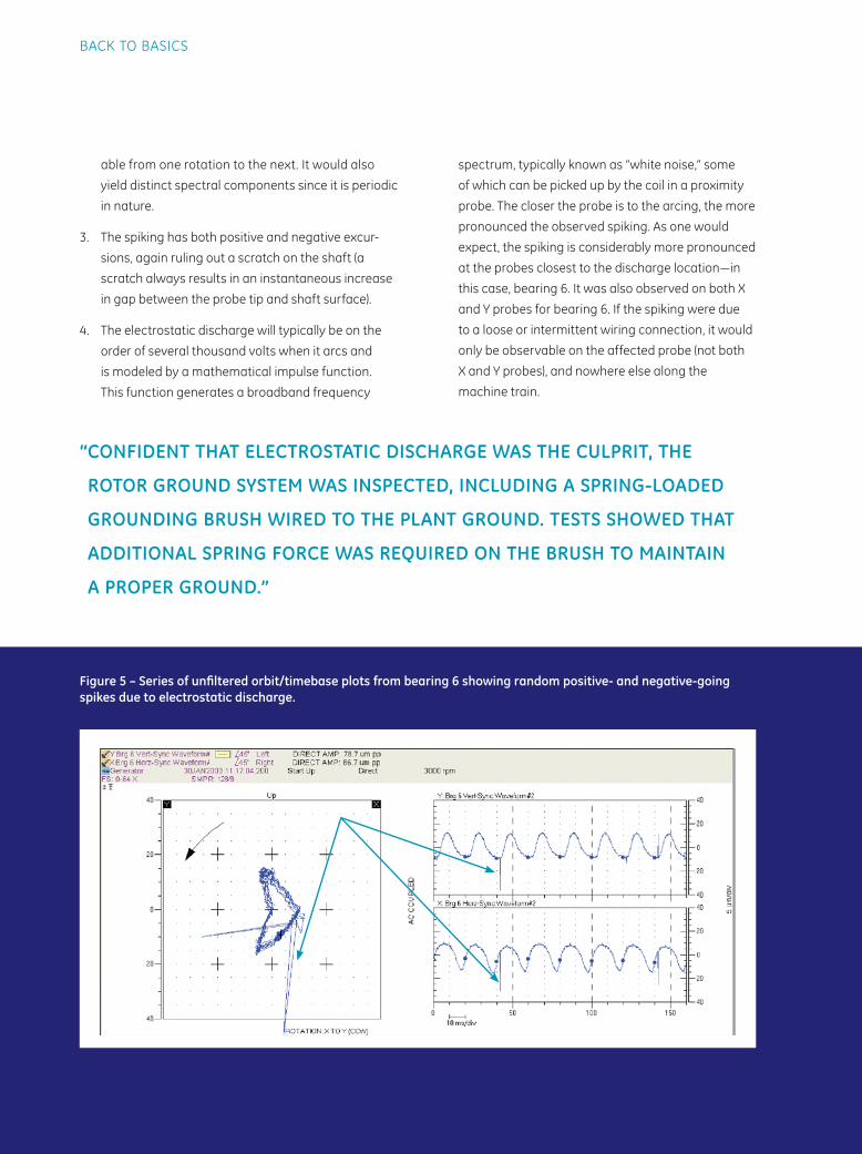
None of these plots explained the presence of the
erratic signals on bearing 6. However, the orbit/time-
base plots shown in Figure 5 exhibited numerous spikes
superimposed on the vibration signal. The spikes were
non-repeatable and were randomly distributed in both
positive and negative directions. They were also absent
or considerably attenuated on some of the other probes
along the machine. And, they were present on both X
and Y probes at the particular bearing. This is a classical
signature of electrostatic discharge induced in rotating
machinery for the following reasons:
1. It is clearly impossible for the shaft to physically
move that quickly and to such an extent as shown
by the spikes, and then immediately resume its
“normal” orbital path inside the bearing clearance.
2. The spiking is non-repeatable. If the spike were the
result of a scratch on the shaft, it would be repeat-
32 ORBIT Vol .27 No.2 2007
BACK TO BASICS
able from one rotation to the next. It would also
yield distinct spectral components since it is periodic
in nature.
3. The spiking has both positive and negative excur-
sions, again ruling out a scratch on the shaft (a
scratch always results in an instantaneous increase
in gap between the probe tip and shaft surface).
4. The electrostatic discharge will typically be on the
order of several thousand volts when it arcs and
is modeled by a mathematical impulse function.
This function generates a broadband frequency
spectrum, typically known as “white noise,” some
of which can be picked up by the coil in a proximity
probe. The closer the probe is to the arcing, the more
pronounced the observed spiking. As one would
expect, the spiking is considerably more pronounced
at the probes closest to the discharge location—in
this case, bearing 6. It was also observed on both X
and Y probes for bearing 6. If the spiking were due
to a loose or intermittent wiring connection, it would
only be observable on the affected probe (not both
X and Y probes), and nowhere else along the
machine train.
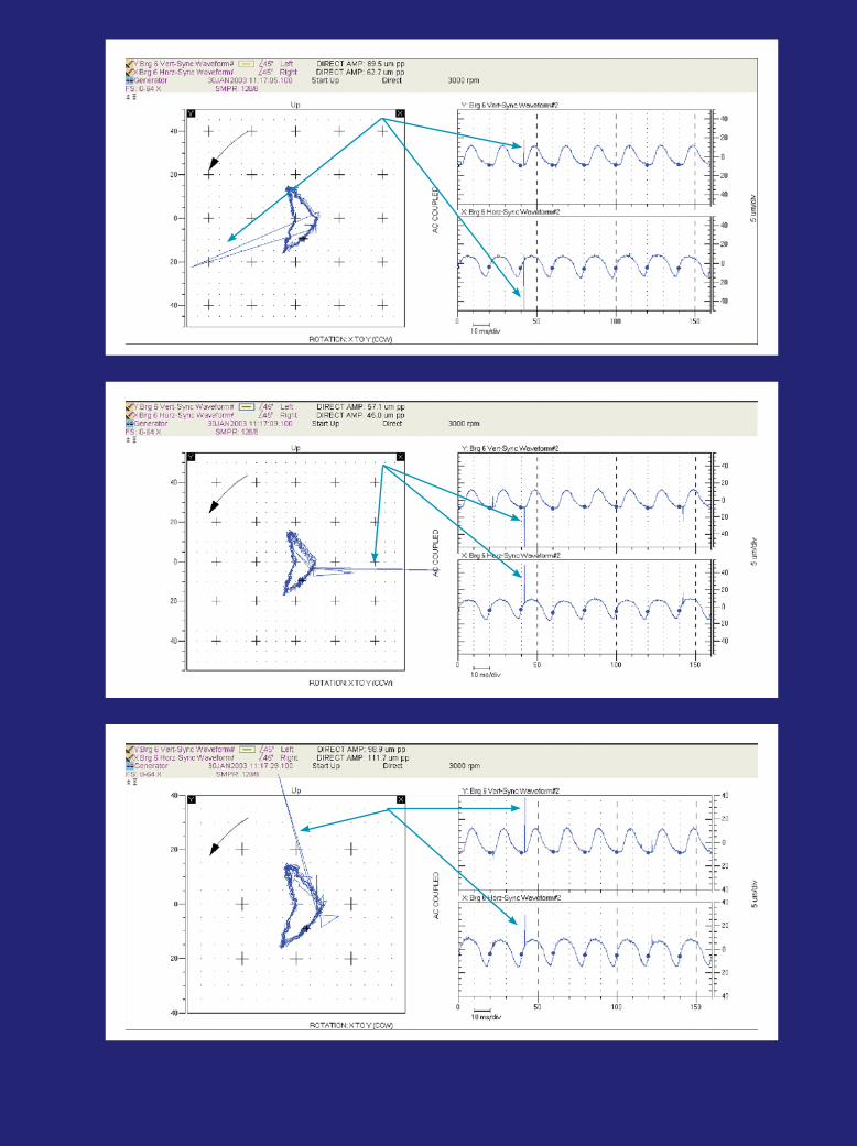
Figure 5 – Series of unfi ltered orbit/timebase plots from bearing 6 showing random positive- and negative-going spikes due to electrostatic discharge.
“ CONFIDENT THAT ELECTROSTATIC DISCHARGE WAS THE CULPRIT, THE
ROTOR GROUND SYSTEM WAS INSPECTED, INCLUDING A SPRING-LOADED
GROUNDING BRUSH WIRED TO THE PLANT GROUND. TESTS SHOWED THAT
ADDITIONAL SPRING FORCE WAS REQUIRED ON THE BRUSH TO MAINTAIN
A PROPER GROUND.”
Vol .27 No.2 2007 ORBIT 33
BACK TO BASICS
34 ORBIT Vol .27 No.2 2007
BACK TO BASICS
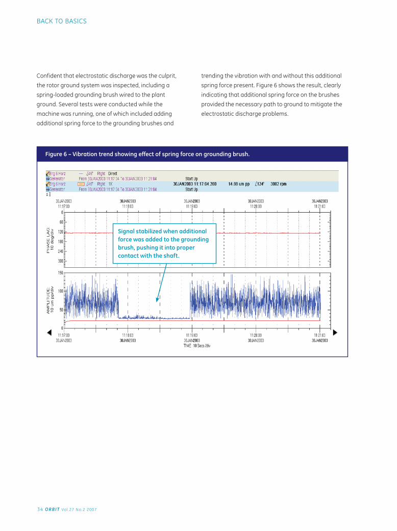
Confident that electrostatic discharge was the culprit,
the rotor ground system was inspected, including a
spring-loaded grounding brush wired to the plant
ground. Several tests were conducted while the
machine was running, one of which included adding
additional spring force to the grounding brushes and
trending the vibration with and without this additional
spring force present. Figure 6 shows the result, clearly
indicating that additional spring force on the brushes
provided the necessary path to ground to mitigate the
electrostatic discharge problems.
Figure 6 – Vibration trend showing effect of spring force on grounding brush.
Signal stabilized when additional force was added to the grounding brush, pushing it into proper contact with the shaft.
Vol .27 No.2 2007 ORBIT 35
BACK TO BASICS
Summary
Electrostatic discharge causes bearing and
machine damage when electrical currents pass
through bearing areas on their way from shaft to
ground, or as they circulate through rotating and
stationary components. This malfunction often
goes undiagnosed because of its subtle symptoms
and gradual effects, and because it is an electrical
phenomenon that manifests itself as mechanical
damage. Even non-electrical machines, such as
turbines and gearboxes, are susceptible because
rotating motion can induce voltage on the shaft
without the presence of a generator. Although
proper maintenance of brushes and insulators is
the first line of defense, failures can occur between
maintenance intervals and inspections. Ideally,
instrumentation that directly measures voltage
and current in the voltage mitigation system will
be available. However, when it is not, a properly
configured vibration monitoring system can also
detect electrostatic discharge and allow timely
intervention before bearing, shaft, or seal damage
occurs.
References
1 Sharke, P., “Current Jam,” Mechanical Engineering, Vol.122 No.5, May 2000, The American Society of Mechanical Engineers.
2 “The Importance of Shaft Centerline Position,” ORBIT Magazine, Vol. 16 No. 2, June 1995, page 26.
3 Gruber, J.M. and Hansen, E.F., “Electrostatic Shaft Voltages on Steam Turbine Rotors,” Transactions of ASME, Vol. 81, Series A, #1, July 1959, pages 97-110.
4 Eisenmann, R., “Machinery Malfunction Diagnosis And Correction” Page 755.
5 Snyder, M., “Electrostatic Discharge in Rotating Machinery,” ORBIT Magazine, Vol. 22 No. 1, February 2001, pp. 23-24.
6 Winterton, J., “Electrostatic Discharge on a Compressor Train,” ORBIT Magazine, Vol. 22 No. 1, February 2001, pp. 25-28.