Embed Size (px)
Citation preview
Oracle FS1-2 Flash Storage System
Expansion Guide
Part Number E63126-01 Oracle FS1-2 Flash Storage System release 6.2
2015 November

Copyright © 2005, 2015, Oracle and/or its affiliates. All rights reserved.
This software and related documentation are provided under a license agreement containing restrictions onuse and disclosure and are protected by intellectual property laws. Except as expressly permitted in yourlicense agreement or allowed by law, you may not use, copy, reproduce, translate, broadcast, modify,license, transmit, distribute, exhibit, perform, publish, or display any part, in any form, or by any means.Reverse engineering, disassembly, or decompilation of this software, unless required by law forinteroperability, is prohibited.
The information contained herein is subject to change without notice and is not warranted to be error-free. Ifyou find any errors, please report them to us in writing.
If this is software or related documentation that is delivered to the U.S. Government or anyone licensing it onbehalf of the U.S. Government, then the following notice is applicable:
U.S. GOVERNMENT END USERS: Oracle programs, including any operating system, integrated software,any programs installed on the hardware, and/or documentation, delivered to U.S. Government end users are"commercial computer software" pursuant to the applicable Federal Acquisition Regulation and agency-specific supplemental regulations. As such, use, duplication, disclosure, modification, and adaptation of theprograms, including any operating system, integrated software, any programs installed on the hardware,and/or documentation, shall be subject to license terms and license restrictions applicable to the programs.No other rights are granted to the U.S. Government.
This software or hardware is developed for general use in a variety of information management applications.It is not developed or intended for use in any inherently dangerous applications, including applications thatmay create a risk of personal injury. If you use this software or hardware in dangerous applications, then youshall be responsible to take all appropriate fail-safe, backup, redundancy, and other measures to ensure itssafe use. Oracle Corporation and its affiliates disclaim any liability for any damages caused by use of thissoftware or hardware in dangerous applications.
Oracle and Java are registered trademarks of Oracle and/or its affiliates. Other names may be trademarks oftheir respective owners.
Intel and Intel Xeon are trademarks or registered trademarks of Intel Corporation. All SPARC trademarks areused under license and are trademarks or registered trademarks of SPARC International, Inc. AMD,Opteron, the AMD logo, and the AMD Opteron logo are trademarks or registered trademarks of AdvancedMicro Devices. UNIX is a registered trademark of The Open Group.
This software or hardware and documentation may provide access to or information about content, products,and services from third parties. Oracle Corporation and its affiliates are not responsible for and expresslydisclaim all warranties of any kind with respect to third-party content, products, and services unlessotherwise set forth in an applicable agreement between you and Oracle. Oracle Corporation and its affiliateswill not be responsible for any loss, costs, or damages incurred due to your access to or use of third-partycontent, products, or services, except as set forth in an applicable agreement between you and Oracle.
Documentation Accessibility
For information about Oracle's commitment to accessibility, visit the Oracle Accessibility Program website at http://www.oracle.com/pls/topic/lookup?ctx=acc&id=docacc.
Access to Oracle Support
Oracle customers that have purchased support have access to electronic support through My OracleSupport. For information, visit http://www.oracle.com/pls/topic/lookup?ctx=acc&id=info or visit http://www.oracle.com/pls/topic/lookup?ctx=acc&id=trs if you are hearing impaired.
ContentsList of Tables ...............................................................................................................................5
List of Figures..............................................................................................................................6
Preface ........................................................................................................................................7Oracle Resources ..................................................................................................................7Related Documentation .........................................................................................................7
Chapter 1: System Expansion.....................................................................................................8Overview ................................................................................................................................8Planning Steps Overview.......................................................................................................8Expansion Planning Worksheet ...........................................................................................10Installation Steps Overview..................................................................................................13
Chapter 2: SAS Cabling Overview ............................................................................................15Drive Enclosure Strings .......................................................................................................15Chassis ID Numbers on Drive Enclosures...........................................................................17Add Order Number of Drive Enclosures ..............................................................................19SAS Cabling Precautions.....................................................................................................23SAS Resiliency ....................................................................................................................24Topology Validation Overview .............................................................................................24
Chapter 3: Installing Drive Enclosures in the Rack ...................................................................26Validate the Current State of the System.............................................................................26Install New Drive Enclosures in a Rack ...............................................................................27
Chapter 4: Cabling New Drive Enclosures ................................................................................28Types of SAS Cables...........................................................................................................28System Expansion Label Kit ................................................................................................30Prepare the System for Cabling New Drive Enclosures ......................................................31Overview of Cabling New Drive Enclosures ........................................................................32Cable a New Drive Enclosure (Guided Maintenance) .........................................................33Cable a New Drive Enclosure (Manual) ...............................................................................34
Beaconing Drive Enclosures ..........................................................................................35Flash LEDs on Drive Enclosures (GUI).....................................................................35Flash LEDs on Drive Enclosures (FSCLI) .................................................................36
Add the First Drive Enclosure to a New String ...............................................................36Add a Second Drive Enclosure to a String .....................................................................37Add a Third Drive Enclosure to a String .........................................................................40Add a Fourth Drive Enclosure to a String .......................................................................43Add a Fifth Drive Enclosure to a String ..........................................................................45
Complete the Expansion Process........................................................................................47
Chapter 5: Adding Solid State Drives........................................................................................49SSD Expansion Kits .............................................................................................................49
3

Add SSDs to a Drive Enclosure ...........................................................................................49
Appendix A: SAS HBAs and String Configuration.....................................................................51Controller Connection Ports and String Numbers................................................................51
Appendix B: Topology Output ...................................................................................................54Sample Topology Output .....................................................................................................54
Index..........................................................................................................................................69
Contents
4
List of TablesTable 1: Oracle resources...........................................................................................................7
Table 2: Oracle FS1-2 expansion planning worksheet (sample)...............................................10
Table 3: New cables summary worksheet (sample)..................................................................13
Table 4: One SAS HBA per Controller......................................................................................20
Table 5: Two SAS HBAs per Controller.....................................................................................21
Table 6: Three SAS HBAs per Controller..................................................................................22
Table 7: Expected messaging...................................................................................................24
Table 8: Mini-SAS to mini-SAS HD cables ...............................................................................28
Table 9: Mini-SAS to mini-SAS cables .....................................................................................29
Table 10: One SAS HBA per Controller....................................................................................51
Table 11: Two SAS HBAs per Controller...................................................................................52
Table 12: Three SAS HBAs per Controller................................................................................52
5
List of FiguresFigure 1: SAS string topology....................................................................................................16
Figure 2: Chassis IDs displayed on the Drive Enclosure chassis..............................................18
Figure 3: Chassis IDs displayed on the Drive Enclosure Overview page..................................19
Figure 4: Chassis IDs displayed in the topology output.............................................................19
Figure 5: Example of mini-SAS to mini-SAS HD cable connectors...........................................29
Figure 6: Example of mini-SAS to mini-SAS cable connectors.................................................30
Figure 7: A label for the end of a cable that connects to the Controller.....................................30
Figure 8: A label for the end of a cable that connects to a Drive Enclosure..............................31
Figure 9: A label for a cable to identify string 4.........................................................................31
Figure 10: First Drive Enclosure and a new string.....................................................................37
Figure 11: First connection for second Drive Enclosure in a string...........................................38
Figure 12: Connection from SAS HBA to DE 2.........................................................................39
Figure 13: Final connection for second Drive Enclosure in string.............................................40
Figure 14: First connection between DE 2 and DE 3 in a string................................................41
Figure 15: Connection from SAS HBA to DE 3.........................................................................42
Figure 16: Final connection for third Drive Enclosure in string..................................................43
Figure 17: Connection for fourth Drive Enclosure in string........................................................44
Figure 18: Connections for fifth Drive Enclosure in string.........................................................46
Figure 19: One SAS HBA per Controller, string numbers, and port numbers...........................51
Figure 20: Two SAS HBAs per Controller, string numbers, and port numbers.........................52
Figure 21: Three SAS HBAs per Controller, string numbers, and port numbers.......................53
Figure 22: Annotated example of Controller sections................................................................55
Figure 23: Annotated example of Drive Enclosures..................................................................57
Figure 24: System with three SAS HBAs and 30 Drive Enclosures (Sample)...........................58
6
Preface
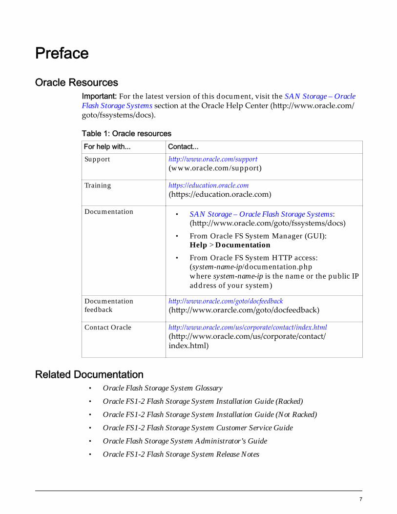
Oracle ResourcesImportant: For the latest version of this document, visit the SAN Storage – OracleFlash Storage Systems section at the Oracle Help Center (http://www.oracle.com/goto/fssystems/docs).
Table 1: Oracle resourcesFor help with... Contact...Support http://www.oracle.com/support
(www.oracle.com/support)
Training https://education.oracle.com(https://education.oracle.com)
Documentation • SAN Storage – Oracle Flash Storage Systems:(http://www.oracle.com/goto/fssystems/docs)
• From Oracle FS System Manager (GUI):Help > Documentation
• From Oracle FS System HTTP access:(system-name-ip/documentation.phpwhere system-name-ip is the name or the public IPaddress of your system)
Documentationfeedback
http://www.oracle.com/goto/docfeedback(http://www.orarcle.com/goto/docfeedback)
Contact Oracle http://www.oracle.com/us/corporate/contact/index.html(http://www.oracle.com/us/corporate/contact/index.html)
Related Documentation• Oracle Flash Storage System Glossary
• Oracle FS1-2 Flash Storage System Installation Guide (Racked)
• Oracle FS1-2 Flash Storage System Installation Guide (Not Racked)
• Oracle FS1-2 Flash Storage System Customer Service Guide
• Oracle Flash Storage System Administrator’s Guide
• Oracle FS1-2 Flash Storage System Release Notes
7
CHAPTER 1
System Expansion
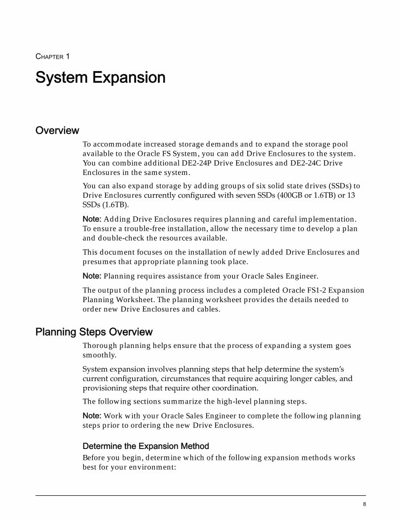
OverviewTo accommodate increased storage demands and to expand the storage poolavailable to the Oracle FS System, you can add Drive Enclosures to the system.You can combine additional DE2-24P Drive Enclosures and DE2-24C DriveEnclosures in the same system.
You can also expand storage by adding groups of six solid state drives (SSDs) toDrive Enclosures currently configured with seven SSDs (400GB or 1.6TB) or 13SSDs (1.6TB).
Note: Adding Drive Enclosures requires planning and careful implementation.To ensure a trouble-free installation, allow the necessary time to develop a planand double-check the resources available.
This document focuses on the installation of newly added Drive Enclosures andpresumes that appropriate planning took place.
Note: Planning requires assistance from your Oracle Sales Engineer.
The output of the planning process includes a completed Oracle FS1-2 ExpansionPlanning Worksheet. The planning worksheet provides the details needed toorder new Drive Enclosures and cables.
Planning Steps OverviewThorough planning helps ensure that the process of expanding a system goessmoothly.
System expansion involves planning steps that help determine the system’scurrent configuration, circumstances that require acquiring longer cables, andprovisioning steps that require other coordination.
The following sections summarize the high-level planning steps.
Note: Work with your Oracle Sales Engineer to complete the following planningsteps prior to ordering the new Drive Enclosures.
Determine the Expansion MethodBefore you begin, determine which of the following expansion methods worksbest for your environment:
8
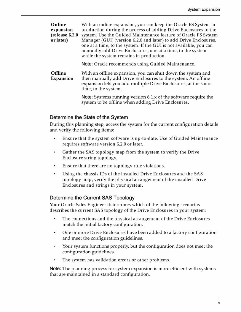
Onlineexpansion(release 6.2.0or later)
With an online expansion, you can keep the Oracle FS System inproduction during the process of adding Drive Enclosures to thesystem. Use the Guided Maintenance feature of Oracle FS SystemManager (GUI) (version 6.2.0 and later) to add Drive Enclosures,one at a time, to the system. If the GUI is not available, you canmanually add Drive Enclosures, one at a time, to the systemwhile the system remains in production.
Note: Oracle recommends using Guided Maintenance.
OfflineExpansion
With an offline expansion, you can shut down the system andthen manually add Drive Enclosures to the system. An offlineexpansion lets you add multiple Drive Enclosures, at the sametime, to the system.
Note: Systems running version 6.1.x of the software require thesystem to be offline when adding Drive Enclosures.
Determine the State of the SystemDuring this planning step, access the system for the current configuration detailsand verify the following items:
• Ensure that the system software is up-to-date. Use of Guided Maintenancerequires software version 6.2.0 or later.
• Gather the SAS topology map from the system to verify the DriveEnclosure string topology.
• Ensure that there are no topology rule violations.
• Using the chassis IDs of the installed Drive Enclosures and the SAStopology map, verify the physical arrangement of the installed DriveEnclosures and strings in your system.
Determine the Current SAS TopologyYour Oracle Sales Engineer determines which of the following scenariosdescribes the current SAS topology of the Drive Enclosures in your system:
• The connections and the physical arrangement of the Drive Enclosuresmatch the initial factory configuration.
• One or more Drive Enclosures have been added to a factory configurationand meet the configuration guidelines.
• Your system functions properly, but the configuration does not meet theconfiguration guidelines.
• The system has validation errors or other problems.
Note: The planning process for system expansion is more efficient with systemsthat are maintained in a standard configuration.
System Expansion
9
Determine the String Numbers and LocationsYour Oracle Sales Engineer analyzes the SAS topology configuration of yoursystem to determine the string number and the location of each new DriveEnclosure within the strings for your system.
Determine a Time to Install the New Drive EnclosuresInstallation should occur during a system offline maintenance period or during atime when the system load is low.
Note: The system is designed so that you can expand the available storage poolduring production while the system remains online. Keeping the system inproduction during expansion has the following requirements:
• The system environment has been designed and maintained in a properstate to allow for an upgrade to be successful.
• You, or someone that you designate, must be knowledgeable in thetechnical aspects of the system, as well as the system environment, prior toperforming the expansion. Otherwise, complete the procedure offline in amaintenance window or contact your Oracle Sales Engineer for assistance.
Related LinksExpansion Planning WorksheetSample Topology Output
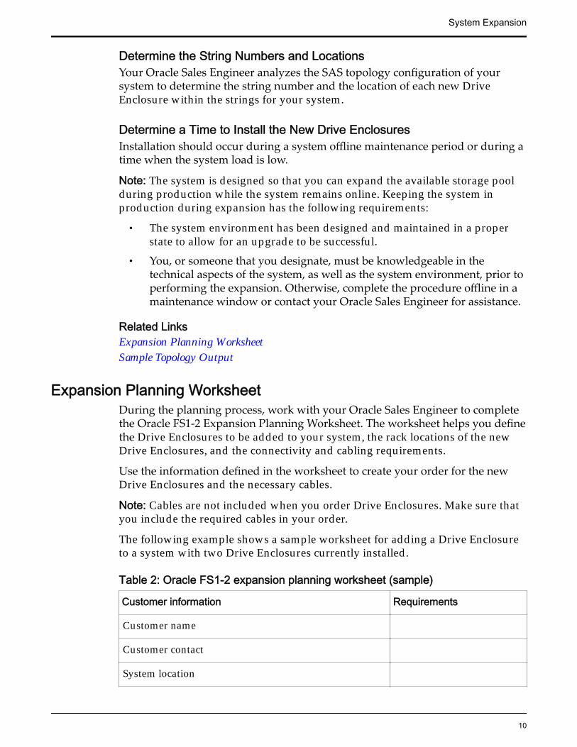
Expansion Planning WorksheetDuring the planning process, work with your Oracle Sales Engineer to completethe Oracle FS1-2 Expansion Planning Worksheet. The worksheet helps you definethe Drive Enclosures to be added to your system, the rack locations of the newDrive Enclosures, and the connectivity and cabling requirements.
Use the information defined in the worksheet to create your order for the newDrive Enclosures and the necessary cables.
Note: Cables are not included when you order Drive Enclosures. Make sure thatyou include the required cables in your order.
The following example shows a sample worksheet for adding a Drive Enclosureto a system with two Drive Enclosures currently installed.
Table 2: Oracle FS1-2 expansion planning worksheet (sample)
Customer information Requirements
Customer name
Customer contact
System location
System Expansion
10
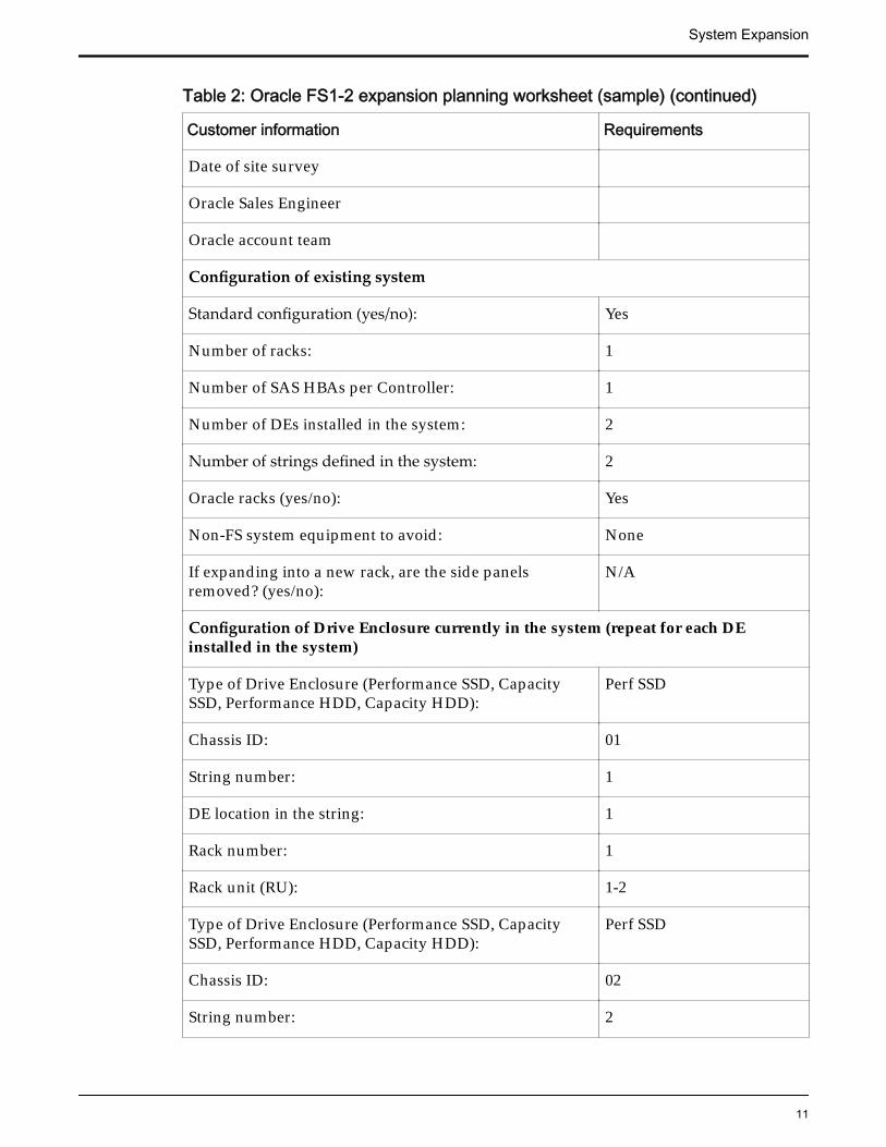
Table 2: Oracle FS1-2 expansion planning worksheet (sample) (continued)
Customer information Requirements
Date of site survey
Oracle Sales Engineer
Oracle account team
Configuration of existing system
Standard configuration (yes/no): Yes
Number of racks: 1
Number of SAS HBAs per Controller: 1
Number of DEs installed in the system: 2
Number of strings defined in the system: 2
Oracle racks (yes/no): Yes
Non-FS system equipment to avoid: None
If expanding into a new rack, are the side panelsremoved? (yes/no):
N/A
Configuration of Drive Enclosure currently in the system (repeat for each DEinstalled in the system)
Type of Drive Enclosure (Performance SSD, CapacitySSD, Performance HDD, Capacity HDD):
Perf SSD
Chassis ID: 01
String number: 1
DE location in the string: 1
Rack number: 1
Rack unit (RU): 1-2
Type of Drive Enclosure (Performance SSD, CapacitySSD, Performance HDD, Capacity HDD):
Perf SSD
Chassis ID: 02
String number: 2
System Expansion
11
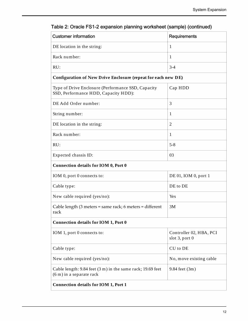
Table 2: Oracle FS1-2 expansion planning worksheet (sample) (continued)
Customer information Requirements
DE location in the string: 1
Rack number: 1
RU: 3-4
Configuration of New Drive Enclosure (repeat for each new DE)
Type of Drive Enclosure (Performance SSD, CapacitySSD, Performance HDD, Capacity HDD):
Cap HDD
DE Add Order number: 3
String number: 1
DE location in the string: 2
Rack number: 1
RU: 5-8
Expected chassis ID: 03
Connection details for IOM 0, Port 0
IOM 0, port 0 connects to: DE 01, IOM 0, port 1
Cable type: DE to DE
New cable required (yes/no): Yes
Cable length (3 meters = same rack; 6 meters = differentrack
3M
Connection details for IOM 1, Port 0
IOM 1, port 0 connects to: Controller 02, HBA, PCIslot 3, port 0
Cable type: CU to DE
New cable required (yes/no): No, move existing cable
Cable length: 9.84 feet (3 m) in the same rack; 19.69 feet(6 m) in a separate rack
9.84 feet (3m)
Connection details for IOM 1, Port 1
System Expansion
12
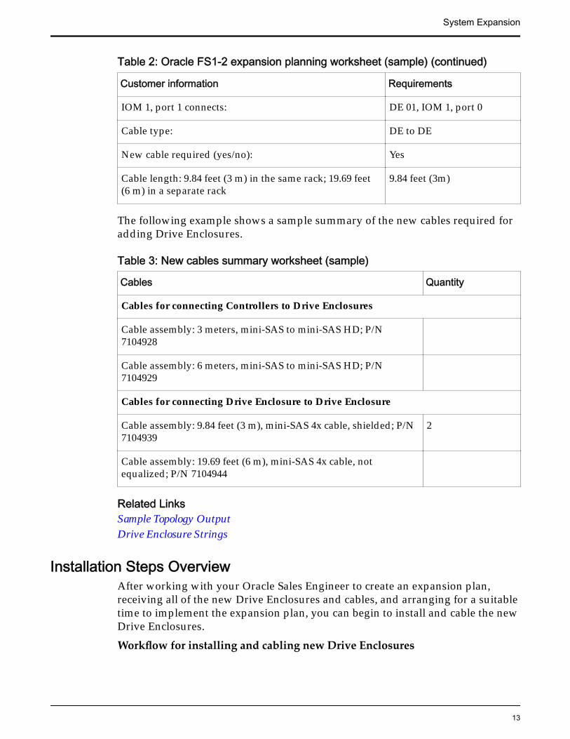
Table 2: Oracle FS1-2 expansion planning worksheet (sample) (continued)
Customer information Requirements
IOM 1, port 1 connects: DE 01, IOM 1, port 0
Cable type: DE to DE
New cable required (yes/no): Yes
Cable length: 9.84 feet (3 m) in the same rack; 19.69 feet(6 m) in a separate rack
9.84 feet (3m)
The following example shows a sample summary of the new cables required foradding Drive Enclosures.
Table 3: New cables summary worksheet (sample)
Cables Quantity
Cables for connecting Controllers to Drive Enclosures
Cable assembly: 3 meters, mini-SAS to mini-SAS HD; P/N7104928
Cable assembly: 6 meters, mini-SAS to mini-SAS HD; P/N7104929
Cables for connecting Drive Enclosure to Drive Enclosure
Cable assembly: 9.84 feet (3 m), mini-SAS 4x cable, shielded; P/N7104939
2
Cable assembly: 19.69 feet (6 m), mini-SAS 4x cable, notequalized; P/N 7104944
Related LinksSample Topology OutputDrive Enclosure Strings
Installation Steps OverviewAfter working with your Oracle Sales Engineer to create an expansion plan,receiving all of the new Drive Enclosures and cables, and arranging for a suitabletime to implement the expansion plan, you can begin to install and cable the newDrive Enclosures.
Workflow for installing and cabling new Drive Enclosures
System Expansion
13
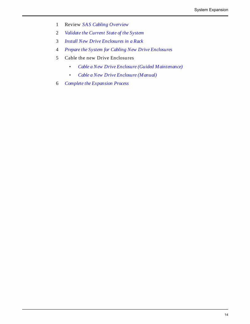
1 Review SAS Cabling Overview
2 Validate the Current State of the System
3 Install New Drive Enclosures in a Rack
4 Prepare the System for Cabling New Drive Enclosures
5 Cable the new Drive Enclosures
• Cable a New Drive Enclosure (Guided Maintenance)
• Cable a New Drive Enclosure (Manual)
6 Complete the Expansion Process
System Expansion
14
CHAPTER 2
SAS Cabling Overview
Drive Enclosure StringsA Drive Enclosure string is a collection of Drive Enclosures that are connected bya common cable to the same SAS HBA port on both Controllers. A string consistsof one to five Drive Enclosures. A system can have up to six strings, dependingupon the number of SAS HBAs installed.
The position of a Drive Enclosure within the SAS topology is determined by thestring number and the location of the Drive Enclosure within the string. Thelocation is determined by the order in which a given Drive Enclosure was addedto the string. The location defines the cable connections for that Drive Enclosure.
For a system expansion to work properly, ensure that the Drive Enclosures andstring distribution adhere to the following guidelines:
• Drive Enclosures are distributed among the strings so that all of theavailable SAS HBA ports designated for Drive Enclosures are used asequally as possible. The number of Drive Enclosures on the shortest stringshould not differ from the number Drive Enclosures on the longest stringby more than one Drive Enclosure.
• Strings are filled in numerical order. No higher numbered string has moreDrive Enclosures installed than a lower numbered string.
The following figure shows a base system with two strings. In a performancesystem where three SAS HBAs are installed per Controller, the arrangement ofthe Drive Enclosures within each string is the same as for base systems. In thefollowing figure, the connections between Controller 1 and I/O module 0 (IOM 0)are shown in red. The connections between Controller 2 and I/O module 1 (IOM1) are shown in green. The connections between Controller 1 and Controller 2,which mirror the SAS cross connections, are shown in purple.
15
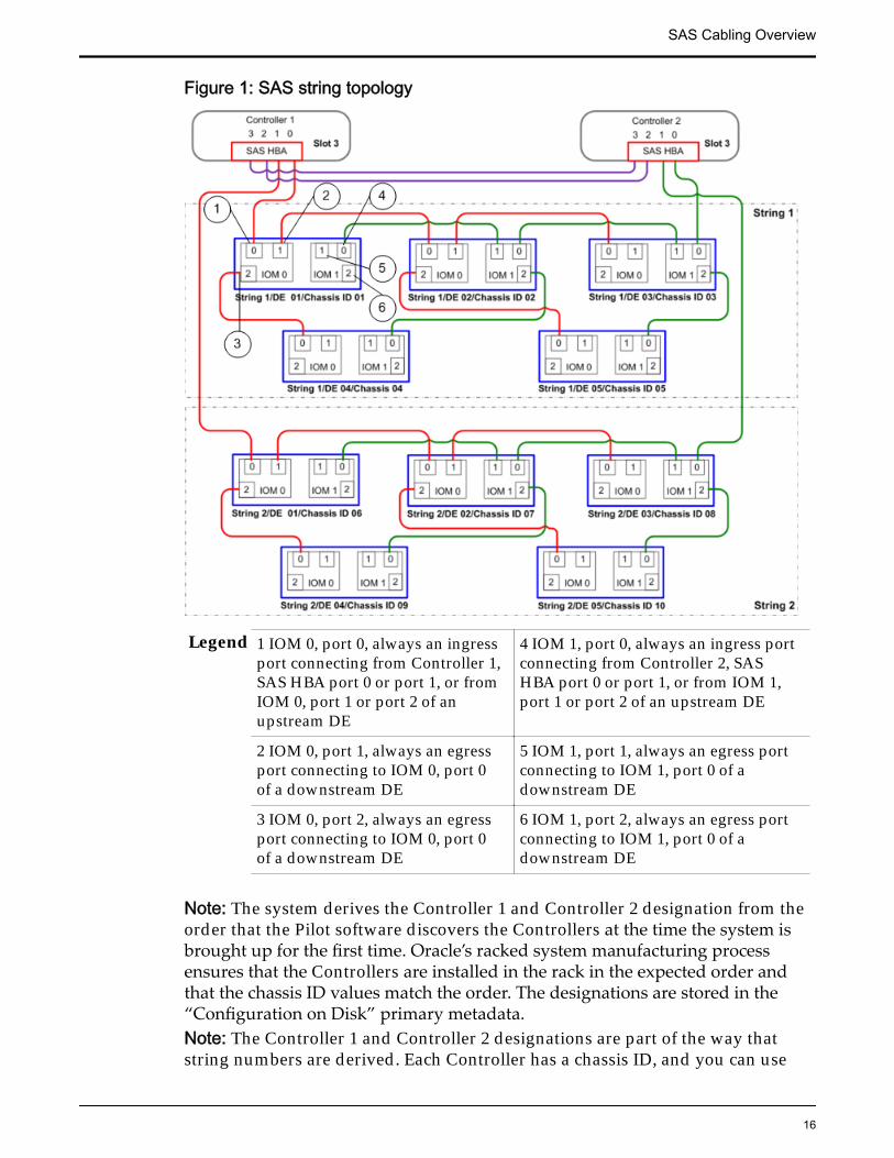
Figure 1: SAS string topology
Legend 1 IOM 0, port 0, always an ingressport connecting from Controller 1,SAS HBA port 0 or port 1, or fromIOM 0, port 1 or port 2 of anupstream DE
4 IOM 1, port 0, always an ingress portconnecting from Controller 2, SASHBA port 0 or port 1, or from IOM 1,port 1 or port 2 of an upstream DE
2 IOM 0, port 1, always an egressport connecting to IOM 0, port 0of a downstream DE
5 IOM 1, port 1, always an egress portconnecting to IOM 1, port 0 of adownstream DE
3 IOM 0, port 2, always an egressport connecting to IOM 0, port 0of a downstream DE
6 IOM 1, port 2, always an egress portconnecting to IOM 1, port 0 of adownstream DE
Note: The system derives the Controller 1 and Controller 2 designation from theorder that the Pilot software discovers the Controllers at the time the system isbrought up for the first time. Oracle’s racked system manufacturing processensures that the Controllers are installed in the rack in the expected order andthat the chassis ID values match the order. The designations are stored in the“Configuration on Disk” primary metadata.Note: The Controller 1 and Controller 2 designations are part of the way thatstring numbers are derived. Each Controller has a chassis ID, and you can use
SAS Cabling Overview
16
Oracle FS System Manager (GUI) or Oracle FS System CLI (FSCLI) to change thechassis IDs. Changing the chassis ID of a Controller does not change the internalController designation.
Related LinksExpansion Planning WorksheetSample Topology OutputCable a New Drive Enclosure (Manual)
Chassis ID Numbers on Drive EnclosuresEach Drive Enclosure has a chassis ID number. The chassis ID number uniquelyidentifies each Drive Enclosure in an Oracle FS System.
Chassis ID AssignmentsAs part of the initial build process, the system assigns chassis IDs to DriveEnclosures based on their location within the discovered topology. If the DriveEnclosures are cabled according to the factory recommendation, the chassis IDsalign with the physical location of the Drive Enclosures in the rack. After a DriveEnclosure has been assigned a chassis ID, the value is persistent across systemwarm starts and cold starts. You can change the chassis ID for a Drive Enclosure,if necessary, to accurately reflect the physical location of the Drive Enclosure inthe rack.
With a factory configuration, chassis ID numbers begin with 01 at the bottom ofthe left-most rack. The chassis ID numbers increment to the top of a rack and leftto right across multiple racks. This assignment of chassis IDs is recommended forall systems to aid service personnel in locating the system components.
For systems with the factory configuration that have not been expanded, theDrive Enclosures are arranged so that the Drive Enclosures in each string arephysically adjacent. The Drive Enclosures have consecutive chassis ID numbers.
When adding Drive Enclosures, the system assigns the next available chassis IDvalue to each newly discovered Drive Enclosure. If chassis ID values weremodified in the system, a newly added Drive Enclosure might be assigned achassis ID value that is lower than the previously installed Drive Enclosures.
Be aware that after successfully expanding a system, the Drive Enclosures in astring will no longer be adjacent in the rack, nor will they have consecutivechassis ID numbers. This is expected and supported. You can use Oracle FSSystem Manager (GUI) or Oracle FS CLI (FSCLI) to change the chassis IDs.
Note: It is not supported to attempt to physically reposition the Drive Enclosuresin the rack to maintain contiguous strings. Repositioning the Drive Enclosures inthe rack can create cable length issues, introduce too much time and risk to theexpansion procedure, and might require the system to be taken offline.
SAS Cabling Overview
17
Very few circumstances cause the chassis ID values to display out of order. Mostof those circumstances indicate that an error has occurred. Be careful whenmodifying chassis ID values.
An example of an out of order chassis ID is on a system restart when the systemwas shut down in order to add several new Drive Enclosures. On startup, thesystem assigns chassis ID numbers to each of the new Drive Enclosures.
If the system cannot find one of the new Drive Enclosures (for example, the DriveEnclosure was not properly powered on or cabled) then that Drive Enclosure willnot be assigned a chassis ID number. Once the issue is resolved, the systemassigns the next available chassis ID number to that Drive Enclosure. Ensure thatyou understand the root cause of any chassis ID coming up out of order beforeproceeding.
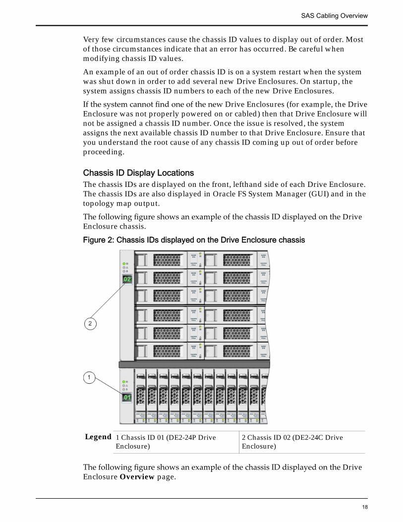
Chassis ID Display LocationsThe chassis IDs are displayed on the front, lefthand side of each Drive Enclosure.The chassis IDs are also displayed in Oracle FS System Manager (GUI) and in thetopology map output.
The following figure shows an example of the chassis ID displayed on the DriveEnclosure chassis.
Figure 2: Chassis IDs displayed on the Drive Enclosure chassis
Legend 1 Chassis ID 01 (DE2-24P DriveEnclosure)
2 Chassis ID 02 (DE2-24C DriveEnclosure)
The following figure shows an example of the chassis ID displayed on the DriveEnclosure Overview page.
SAS Cabling Overview
18
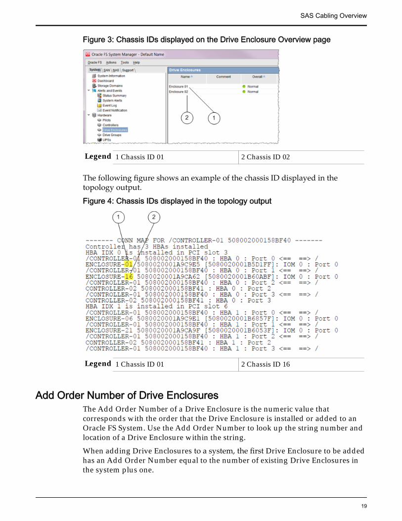
Figure 3: Chassis IDs displayed on the Drive Enclosure Overview page
Legend 1 Chassis ID 01 2 Chassis ID 02
The following figure shows an example of the chassis ID displayed in thetopology output.
Figure 4: Chassis IDs displayed in the topology output
Legend 1 Chassis ID 01 2 Chassis ID 16
Add Order Number of Drive EnclosuresThe Add Order Number of a Drive Enclosure is the numeric value thatcorresponds with the order that the Drive Enclosure is installed or added to anOracle FS System. Use the Add Order Number to look up the string number andlocation of a Drive Enclosure within the string.
When adding Drive Enclosures to a system, the first Drive Enclosure to be addedhas an Add Order Number equal to the number of existing Drive Enclosures inthe system plus one.
SAS Cabling Overview
19
For example, if a system has six Drive Enclosures installed, then the next DriveEnclosure to be added is Add Order Number 7. If the system follows the factoryconfiguration, the chassis ID numbers of the existing Drive Enclosures are 01-06,and the newly added Drive Enclosure is assigned chassis ID number 07.
Note: Depending on the history of the system configuration, the Add OrderNumbers might not match the chassis IDs values of the Drive Enclosures in thesystem.
Note: The chassis IDs should reflect the cabling string order. You can useOracle FS System Manager (GUI) or Oracle FS CLI (FSCLI) to modify the chassisIDs to reflect the cabling string order. Exercise caution when modifying chassisIDs to ensure that the modifications reflect the proper order.
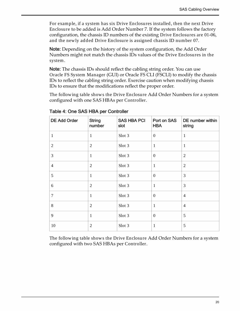
The following table shows the Drive Enclosure Add Order Numbers for a systemconfigured with one SAS HBAs per Controller.
Table 4: One SAS HBA per Controller
DE Add Order Stringnumber
SAS HBA PCIslot
Port on SASHBA
DE number withinstring
1 1 Slot 3 0 1
2 2 Slot 3 1 1
3 1 Slot 3 0 2
4 2 Slot 3 1 2
5 1 Slot 3 0 3
6 2 Slot 3 1 3
7 1 Slot 3 0 4
8 2 Slot 3 1 4
9 1 Slot 3 0 5
10 2 Slot 3 1 5
The following table shows the Drive Enclosure Add Order Numbers for a systemconfigured with two SAS HBAs per Controller.
SAS Cabling Overview
20
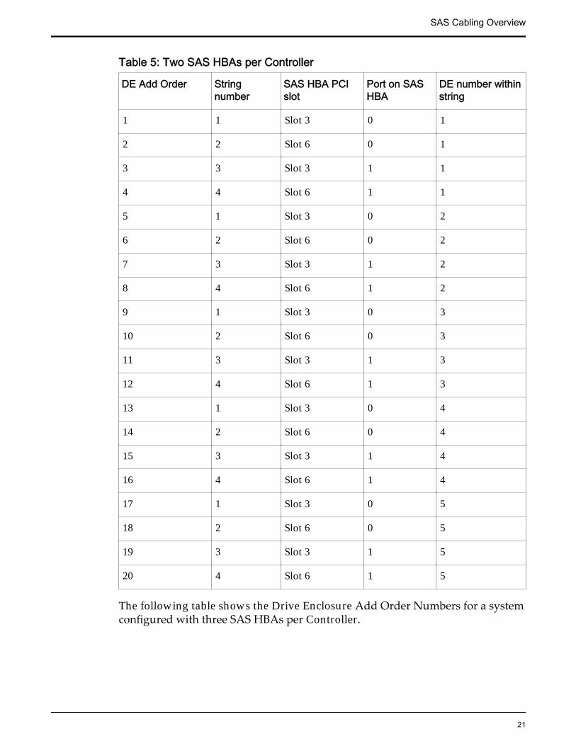
Table 5: Two SAS HBAs per Controller
DE Add Order Stringnumber
SAS HBA PCIslot
Port on SASHBA
DE number withinstring
1 1 Slot 3 0 1
2 2 Slot 6 0 1
3 3 Slot 3 1 1
4 4 Slot 6 1 1
5 1 Slot 3 0 2
6 2 Slot 6 0 2
7 3 Slot 3 1 2
8 4 Slot 6 1 2
9 1 Slot 3 0 3
10 2 Slot 6 0 3
11 3 Slot 3 1 3
12 4 Slot 6 1 3
13 1 Slot 3 0 4
14 2 Slot 6 0 4
15 3 Slot 3 1 4
16 4 Slot 6 1 4
17 1 Slot 3 0 5
18 2 Slot 6 0 5
19 3 Slot 3 1 5
20 4 Slot 6 1 5
The following table shows the Drive Enclosure Add Order Numbers for a systemconfigured with three SAS HBAs per Controller.
SAS Cabling Overview
21
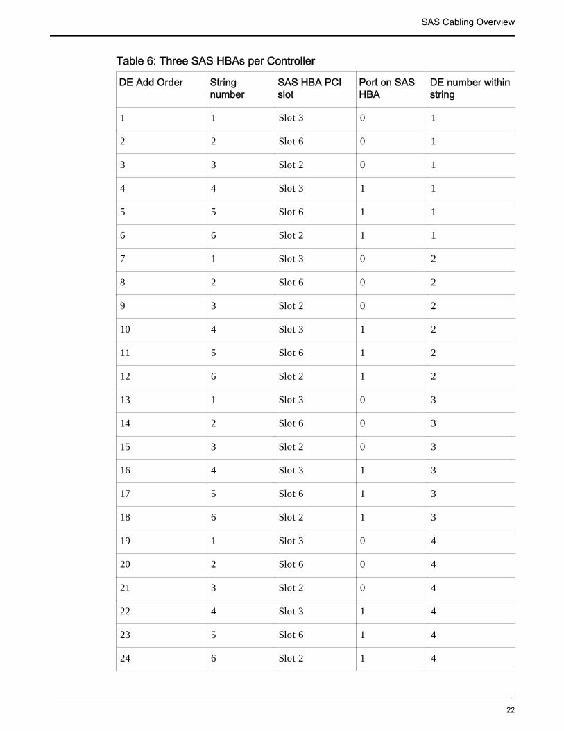
Table 6: Three SAS HBAs per Controller
DE Add Order Stringnumber
SAS HBA PCIslot
Port on SASHBA
DE number withinstring
1 1 Slot 3 0 1
2 2 Slot 6 0 1
3 3 Slot 2 0 1
4 4 Slot 3 1 1
5 5 Slot 6 1 1
6 6 Slot 2 1 1
7 1 Slot 3 0 2
8 2 Slot 6 0 2
9 3 Slot 2 0 2
10 4 Slot 3 1 2
11 5 Slot 6 1 2
12 6 Slot 2 1 2
13 1 Slot 3 0 3
14 2 Slot 6 0 3
15 3 Slot 2 0 3
16 4 Slot 3 1 3
17 5 Slot 6 1 3
18 6 Slot 2 1 3
19 1 Slot 3 0 4
20 2 Slot 6 0 4
21 3 Slot 2 0 4
22 4 Slot 3 1 4
23 5 Slot 6 1 4
24 6 Slot 2 1 4
SAS Cabling Overview
22
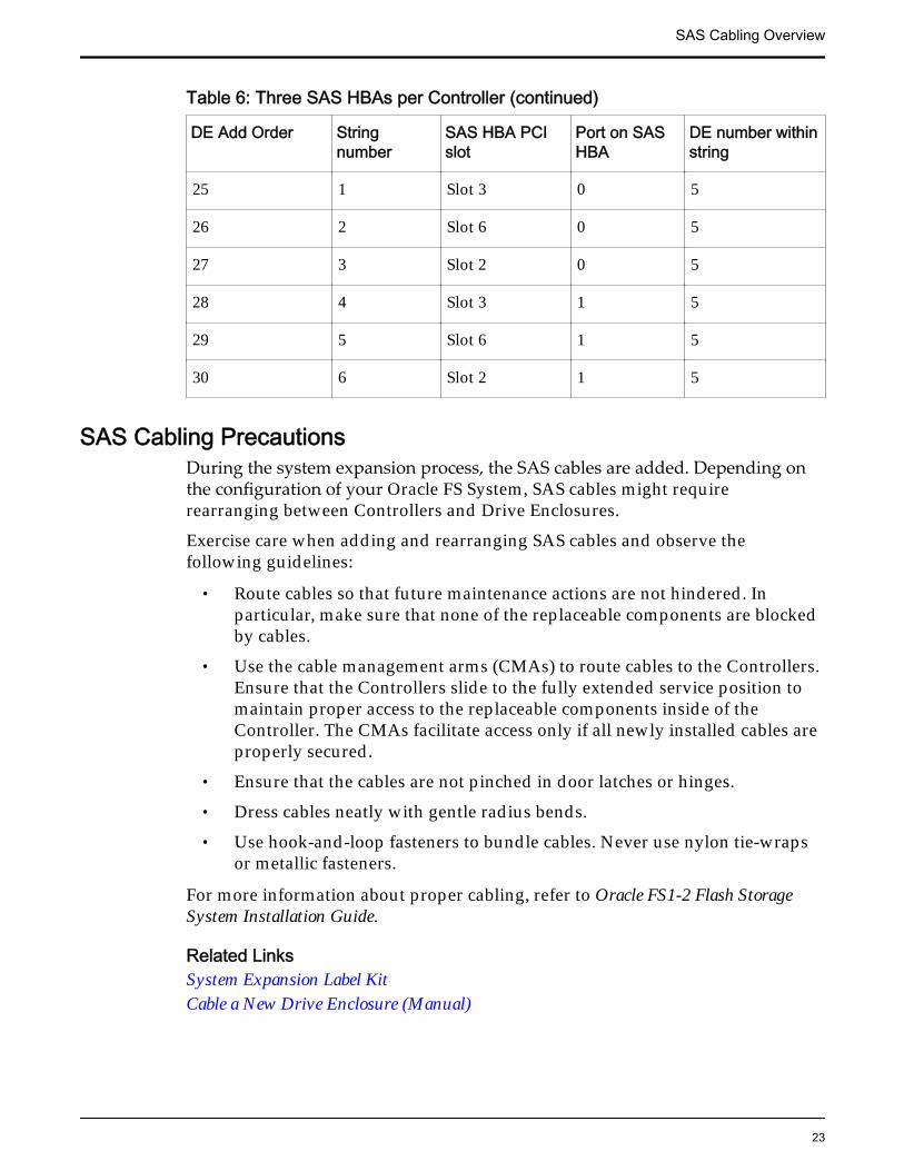
Table 6: Three SAS HBAs per Controller (continued)
DE Add Order Stringnumber
SAS HBA PCIslot
Port on SASHBA
DE number withinstring
25 1 Slot 3 0 5
26 2 Slot 6 0 5
27 3 Slot 2 0 5
28 4 Slot 3 1 5
29 5 Slot 6 1 5
30 6 Slot 2 1 5
SAS Cabling PrecautionsDuring the system expansion process, the SAS cables are added. Depending onthe configuration of your Oracle FS System, SAS cables might requirerearranging between Controllers and Drive Enclosures.
Exercise care when adding and rearranging SAS cables and observe thefollowing guidelines:
• Route cables so that future maintenance actions are not hindered. Inparticular, make sure that none of the replaceable components are blockedby cables.
• Use the cable management arms (CMAs) to route cables to the Controllers.Ensure that the Controllers slide to the fully extended service position tomaintain proper access to the replaceable components inside of theController. The CMAs facilitate access only if all newly installed cables areproperly secured.
• Ensure that the cables are not pinched in door latches or hinges.
• Dress cables neatly with gentle radius bends.
• Use hook-and-loop fasteners to bundle cables. Never use nylon tie-wrapsor metallic fasteners.
For more information about proper cabling, refer to Oracle FS1-2 Flash StorageSystem Installation Guide.
Related LinksSystem Expansion Label KitCable a New Drive Enclosure (Manual)
SAS Cabling Overview
23
SAS ResiliencyWhen adding Drive Enclosures to the second and third location within a string,you must disconnect one of the two cables connecting the string to theControllers. To support continuous access to the data on the string during thetime of this disconnection, the Oracle FS System reroutes all traffic to that stringto the remaining Controller connection.
It can take the system up to 30 seconds for the system to reroute the data traffic.During this time, the system is vulnerable to additional failures or errors. Toverify whether the system has stabilized, log into Oracle FS System Manager(GUI) and monitor the System Alerts page (System > Alerts and Events >System Alerts).
Expect event messaging that shows the topology rule violations that corollateexactly to the cable pulls. If, for example, you disconnect a Drive Enclosure portin the path of Controller 01, you should expect messaging related to Controller01.
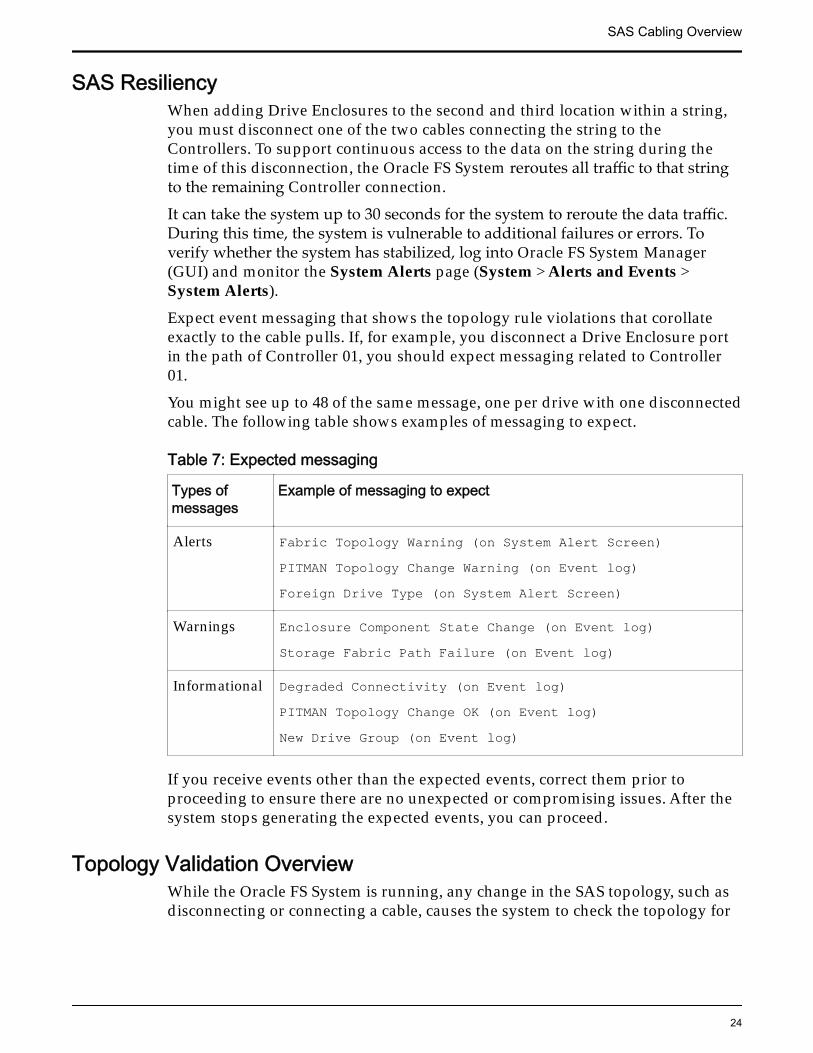
You might see up to 48 of the same message, one per drive with one disconnectedcable. The following table shows examples of messaging to expect.
Table 7: Expected messaging
Types ofmessages
Example of messaging to expect
Alerts Fabric Topology Warning (on System Alert Screen)PITMAN Topology Change Warning (on Event log)Foreign Drive Type (on System Alert Screen)
Warnings Enclosure Component State Change (on Event log)Storage Fabric Path Failure (on Event log)
Informational Degraded Connectivity (on Event log)PITMAN Topology Change OK (on Event log)New Drive Group (on Event log)
If you receive events other than the expected events, correct them prior toproceeding to ensure there are no unexpected or compromising issues. After thesystem stops generating the expected events, you can proceed.
Topology Validation OverviewWhile the Oracle FS System is running, any change in the SAS topology, such asdisconnecting or connecting a cable, causes the system to check the topology for
SAS Cabling Overview
24

alerts. Continuously monitor the alerts during the expansion procedure to assurethat no topology violations occur.
It can take up to 30 seconds for the system to post alerts. Use Oracle FS SystemManager (GUI) or Oracle FS CLI (FSCLI) to monitor the system alerts:
• Using the GUI, navigate to System > Alerts and Events > System Alerts.
• Using the FSCLI, issue fscli topology -list -violations.
Related LinksSample Topology OutputValidate the Current State of the System
SAS Cabling Overview
25
CHAPTER 3
Installing Drive Enclosures in the Rack
Validate the Current State of the SystemBefore installing new Drive Enclosures, it is imperative that the current state ofthe Oracle FS System matches the state of the system when the expansion planwas created. Changes in the SAS topology and the configuration of DriveEnclosure strings between the time that the expansion plan was completed andthe time of the installation can render the plan invalid. Changes can also bepotentially dangerous to system stability.
Prerequisites: • The current version of Oracle FS System Manager (GUI) isinstalled on your client workstation.
• The current version of Oracle FS CLI (FSCLI) is installed onyour client workstation.
For details about updating the GUI and the FSCLI, refer to OracleFlash Storage System Administrator’s Guide.
Important: If the current state of the system does not match the state of thesystem when the expansion plan was created, stop the installation and consultwith your Oracle Sales Engineer.
1 Make sure that the system has no topology violations.
a) Using an account set up with support role privileges, log into theFSCLI and issue fscli topology -list -violations.
b) Correct any topology violations before proceeding.
2 Gather the current state of the system’s SAS topology and configuration ofDrive Enclosure strings.
a) Log into the FSCLI and issue fscli topology –download –topomap <output-text-file>.
The system returns a file containing the topology map.
b) Compare the current topology map with the topology map capturedduring the planning process.
The topology map contains the SAS topology and the currentconfiguration of Drive Enclosure strings. If the current topology mapmatches the topology map captured during the planning process,proceed with the installation of the new Drive Enclosures.
26
Otherwise, analyze the topology map to determine if the system canbe updated in a straightforward way.
For a system expansion to work properly, the Drive Enclosures thatare currently installed must meet the following criteria:
• The SAS topology must be free from rule violations.
• Drive Enclosures and strings distribution adhere to therecommended guidelines.
Related LinksSample Topology OutputTopology Validation Overview
Install New Drive Enclosures in a RackAfter receiving and unpacking the new Drive Enclosures and accessories,prepare the racks and set up the Drive Enclosures in the racks.
Prerequisite: You have access to Oracle FS1-2 Flash Storage System CustomerService Guide.
Note: Contact your Oracle Sales Engineer if you need assistance with your order.
1 (Optional) Upgrade the racks and power distribution units (PDUs).
For more information about racks and PDUs, refer to Oracle FS1-2 FlashStorage System Customer Service Guide.
2 Install the rack rails for each new Drive Enclosure.
For detailed instructions about installing rack rails, refer to Oracle FS1-2Flash Storage System Customer Service Guide.
3 Install each new Drive Enclosure into the rack slot identified in yourexpansion plan.
For detailed instructions about installing Drive Enclosures into racks, referto Oracle FS1-2 Flash Storage System Customer Service Guide.
4 Attach the power cords, and then power on the new Drive Enclosures.
Note: Do not attach any of the SAS cables at this time.
Installing Drive Enclosures in the Rack
27
CHAPTER 4
Cabling New Drive Enclosures
Types of SAS CablesMini-SAS to mini-SAS HD cables connect Controllersto Drive Enclosures. Mini-SAS to mini-SAS cables connect Drive Enclosures to Drive Enclosures.
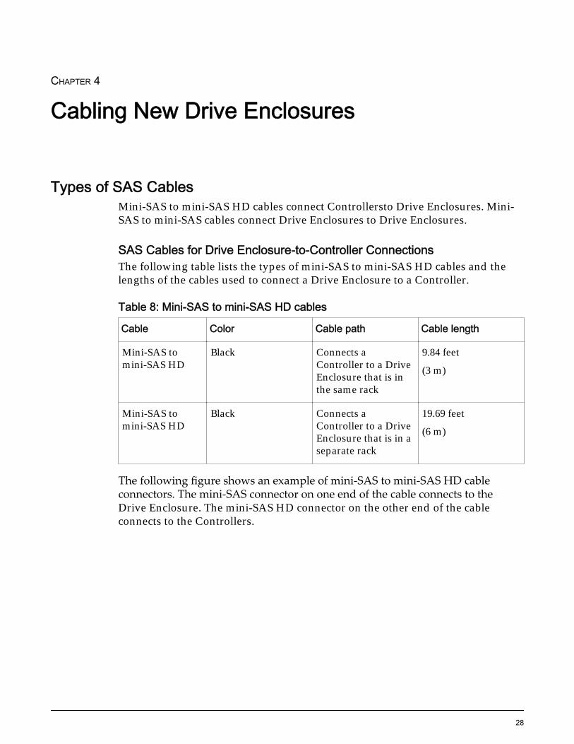
SAS Cables for Drive Enclosure-to-Controller ConnectionsThe following table lists the types of mini-SAS to mini-SAS HD cables and thelengths of the cables used to connect a Drive Enclosure to a Controller.
Table 8: Mini-SAS to mini-SAS HD cables
Cable Color Cable path Cable length
Mini-SAS tomini-SAS HD
Black Connects aController to a DriveEnclosure that is inthe same rack
9.84 feet
(3 m)
Mini-SAS tomini-SAS HD
Black Connects aController to a DriveEnclosure that is in aseparate rack
19.69 feet
(6 m)
The following figure shows an example of mini-SAS to mini-SAS HD cableconnectors. The mini-SAS connector on one end of the cable connects to theDrive Enclosure. The mini-SAS HD connector on the other end of the cableconnects to the Controllers.
28
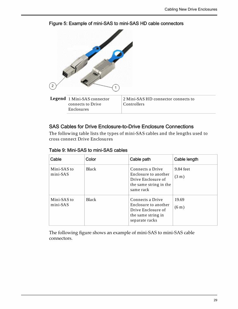
Figure 5: Example of mini-SAS to mini-SAS HD cable connectors
Legend 1 Mini-SAS connectorconnects to DriveEnclosures
2 Mini-SAS HD connector connects toControllers
SAS Cables for Drive Enclosure-to-Drive Enclosure ConnectionsThe following table lists the types of mini-SAS cables and the lengths used tocross connect Drive Enclosures
Table 9: Mini-SAS to mini-SAS cables
Cable Color Cable path Cable length
Mini-SAS tomini-SAS
Black Connects a DriveEnclosure to anotherDrive Enclosure ofthe same string in thesame rack
9.84 feet
(3 m)
Mini-SAS tomini-SAS
Black Connects a DriveEnclosure to anotherDrive Enclosure ofthe same string inseparate racks
19.69
(6 m)
The following figure shows an example of mini-SAS to mini-SAS cableconnectors.
Cabling New Drive Enclosures
29
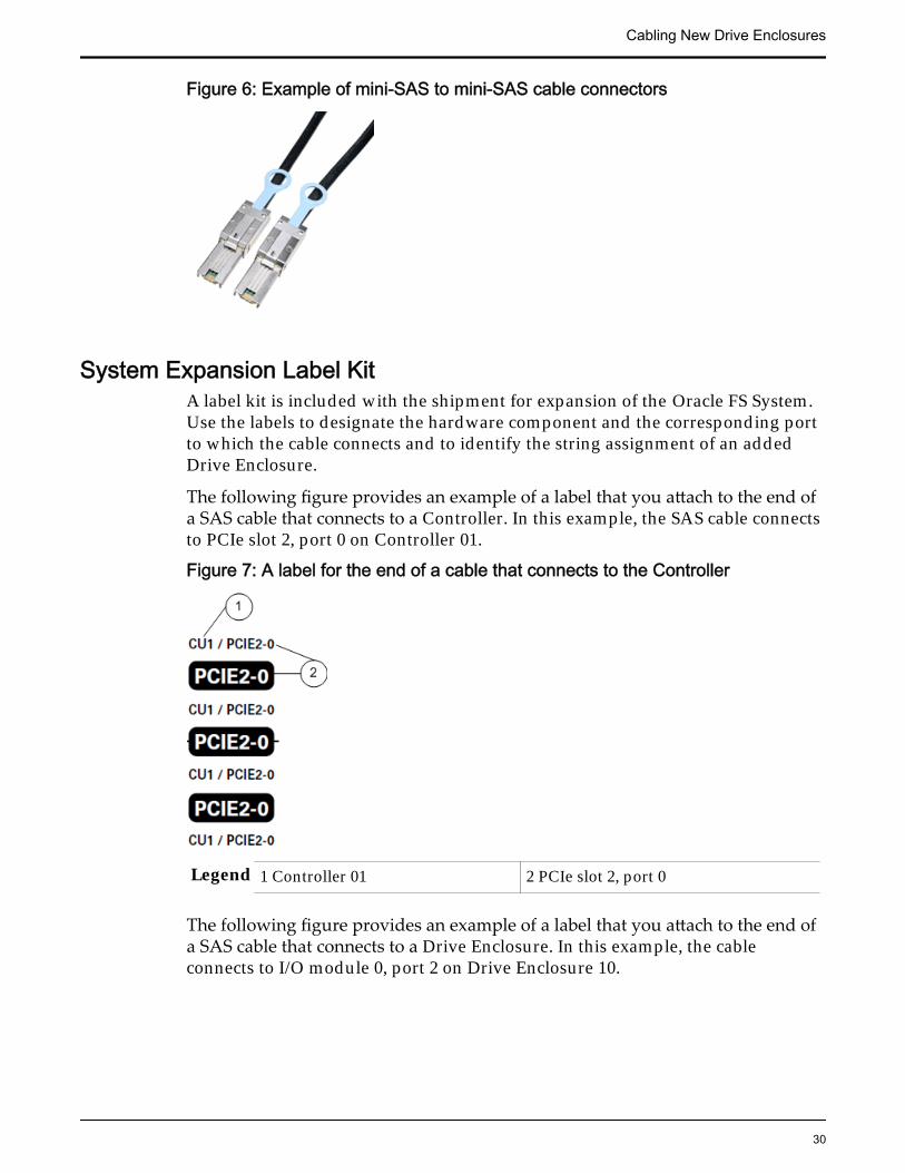
Figure 6: Example of mini-SAS to mini-SAS cable connectors
System Expansion Label KitA label kit is included with the shipment for expansion of the Oracle FS System.Use the labels to designate the hardware component and the corresponding portto which the cable connects and to identify the string assignment of an addedDrive Enclosure.
The following figure provides an example of a label that you attach to the end ofa SAS cable that connects to a Controller. In this example, the SAS cable connectsto PCIe slot 2, port 0 on Controller 01.
Figure 7: A label for the end of a cable that connects to the Controller
Legend 1 Controller 01 2 PCIe slot 2, port 0
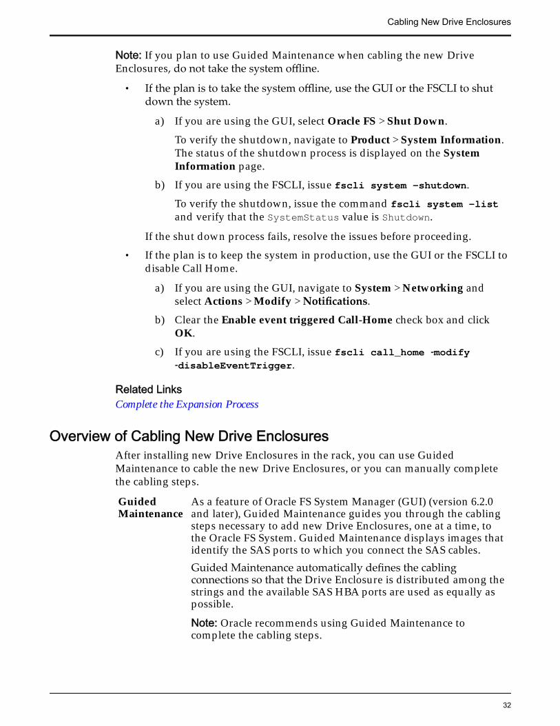
The following figure provides an example of a label that you attach to the end ofa SAS cable that connects to a Drive Enclosure. In this example, the cableconnects to I/O module 0, port 2 on Drive Enclosure 10.
Cabling New Drive Enclosures
30
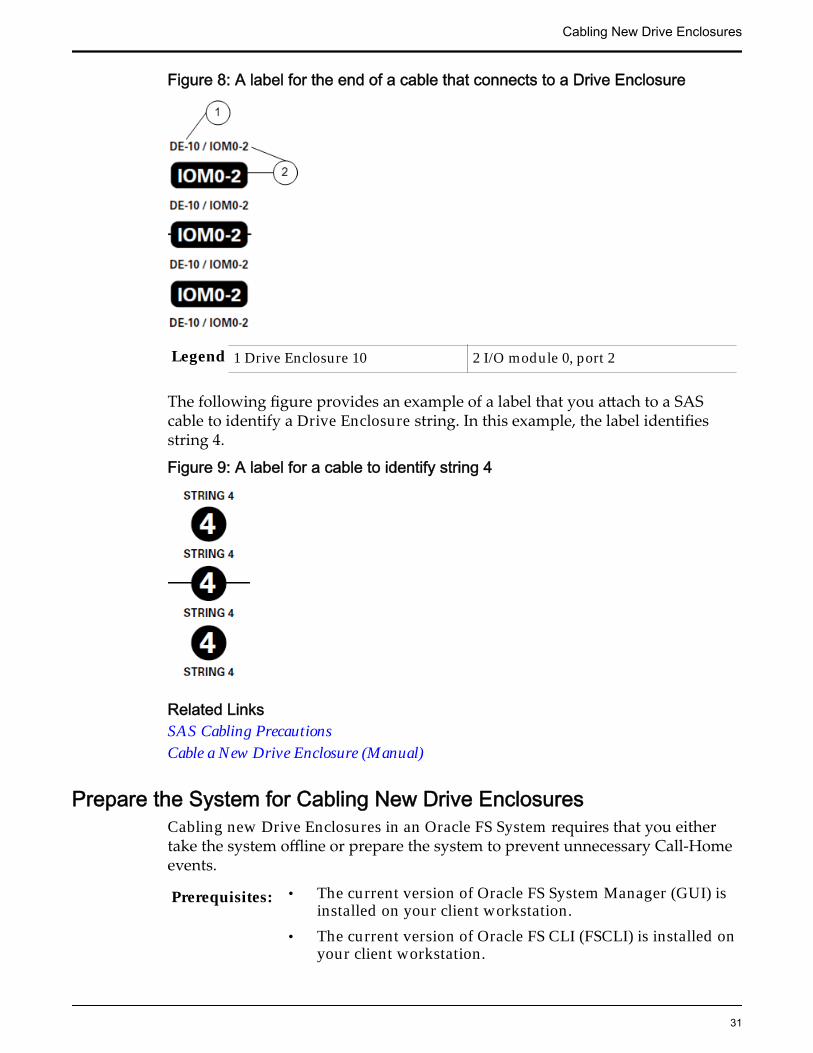
Figure 8: A label for the end of a cable that connects to a Drive Enclosure
Legend 1 Drive Enclosure 10 2 I/O module 0, port 2
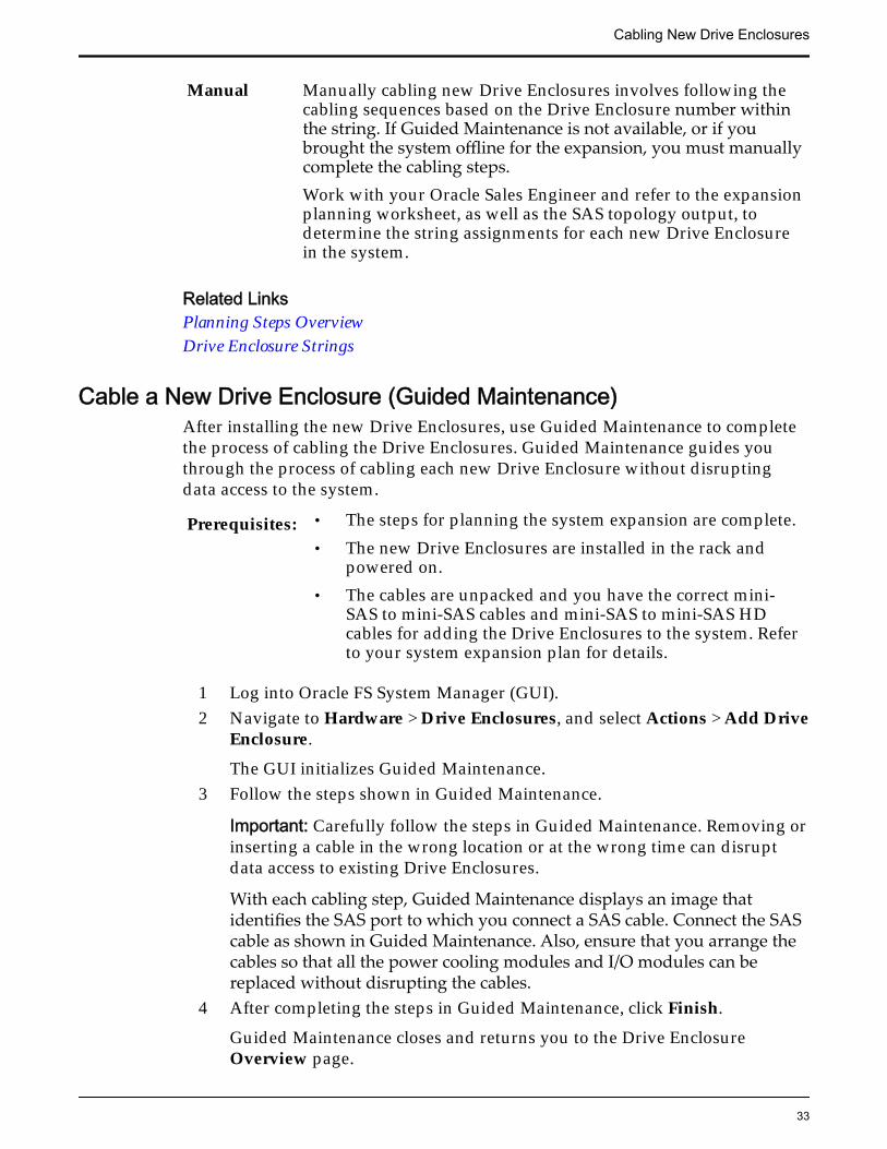
The following figure provides an example of a label that you attach to a SAScable to identify a Drive Enclosure string. In this example, the label identifiesstring 4.
Figure 9: A label for a cable to identify string 4
Related LinksSAS Cabling PrecautionsCable a New Drive Enclosure (Manual)
Prepare the System for Cabling New Drive EnclosuresCabling new Drive Enclosures in an Oracle FS System requires that you eithertake the system offline or prepare the system to prevent unnecessary Call-Homeevents.
Prerequisites: • The current version of Oracle FS System Manager (GUI) isinstalled on your client workstation.
• The current version of Oracle FS CLI (FSCLI) is installed onyour client workstation.
Cabling New Drive Enclosures
31
Note: If you plan to use Guided Maintenance when cabling the new DriveEnclosures, do not take the system offline.
• If the plan is to take the system offline, use the GUI or the FSCLI to shutdown the system.
a) If you are using the GUI, select Oracle FS > Shut Down.
To verify the shutdown, navigate to Product > System Information.The status of the shutdown process is displayed on the SystemInformation page.
b) If you are using the FSCLI, issue fscli system -shutdown.
To verify the shutdown, issue the command fscli system -listand verify that the SystemStatus value is Shutdown.
If the shut down process fails, resolve the issues before proceeding.
• If the plan is to keep the system in production, use the GUI or the FSCLI todisable Call Home.
a) If you are using the GUI, navigate to System > Networking andselect Actions > Modify > Notifications.
b) Clear the Enable event triggered Call-Home check box and clickOK.
c) If you are using the FSCLI, issue fscli call_home ‑modify‑disableEventTrigger.
Related LinksComplete the Expansion Process
Overview of Cabling New Drive EnclosuresAfter installing new Drive Enclosures in the rack, you can use GuidedMaintenance to cable the new Drive Enclosures, or you can manually completethe cabling steps.
GuidedMaintenance
As a feature of Oracle FS System Manager (GUI) (version 6.2.0and later), Guided Maintenance guides you through the cablingsteps necessary to add new Drive Enclosures, one at a time, tothe Oracle FS System. Guided Maintenance displays images thatidentify the SAS ports to which you connect the SAS cables.Guided Maintenance automatically defines the cablingconnections so that the Drive Enclosure is distributed among thestrings and the available SAS HBA ports are used as equally aspossible.
Note: Oracle recommends using Guided Maintenance tocomplete the cabling steps.
Cabling New Drive Enclosures
32
Manual Manually cabling new Drive Enclosures involves following thecabling sequences based on the Drive Enclosure number withinthe string. If Guided Maintenance is not available, or if youbrought the system offline for the expansion, you must manuallycomplete the cabling steps.Work with your Oracle Sales Engineer and refer to the expansionplanning worksheet, as well as the SAS topology output, todetermine the string assignments for each new Drive Enclosurein the system.
Related LinksPlanning Steps OverviewDrive Enclosure Strings
Cable a New Drive Enclosure (Guided Maintenance)After installing the new Drive Enclosures, use Guided Maintenance to completethe process of cabling the Drive Enclosures. Guided Maintenance guides youthrough the process of cabling each new Drive Enclosure without disruptingdata access to the system.
Prerequisites: • The steps for planning the system expansion are complete.• The new Drive Enclosures are installed in the rack and
powered on.• The cables are unpacked and you have the correct mini-
SAS to mini-SAS cables and mini-SAS to mini-SAS HDcables for adding the Drive Enclosures to the system. Referto your system expansion plan for details.
1 Log into Oracle FS System Manager (GUI).2 Navigate to Hardware > Drive Enclosures, and select Actions > Add Drive
Enclosure.
The GUI initializes Guided Maintenance.3 Follow the steps shown in Guided Maintenance.
Important: Carefully follow the steps in Guided Maintenance. Removing orinserting a cable in the wrong location or at the wrong time can disruptdata access to existing Drive Enclosures.
With each cabling step, Guided Maintenance displays an image thatidentifies the SAS port to which you connect a SAS cable. Connect the SAScable as shown in Guided Maintenance. Also, ensure that you arrange thecables so that all the power cooling modules and I/O modules can bereplaced without disrupting the cables.
4 After completing the steps in Guided Maintenance, click Finish.
Guided Maintenance closes and returns you to the Drive EnclosureOverview page.
Cabling New Drive Enclosures
33
5 Complete the expansion process.
6 Repeat the procedures for cabling a new Drive Enclosure for each DriveEnclosure planned for the system expansion.
Related LinksComplete the Expansion ProcessOverview of Cabling New Drive Enclosures
Cable a New Drive Enclosure (Manual)If you do not use Guided Maintenance to add a new Drive Enclosure, carefullyfollow the manual cabling sequences based on the Drive Enclosure numberwithin the string. Work with your Oracle Sales Engineer and refer to theplanning worksheet to determine the string assignments for each new DriveEnclosures.
Prerequisites: • The steps for planning the system expansion are complete.• The new Drive Enclosures are installed in the rack and
powered on.• The cables are unpacked and you have the correct mini-
SAS to mini-SAS cables and mini-SAS to mini-SAS HDcables for adding the Drive Enclosures to the system. Referto your system expansion plan for details.
If the Oracle FS System remained in production for the Drive Enclosure addprocedure, adding the second and third Drive Enclosure to a string requires thesystem to re-route I/O traffic around the connections that are temporarilydisrupted. System connections are not interrupted when you add the first,fourth, and fifth Drive Enclosure to a string.
Note: If the system remained in production, continually be aware of the state ofthe system when adding Drive Enclosures. The configuration of the system hasdual paths for all of the required connections within the system. During parts ofthe procedures for adding a Drive Enclosure, one of those paths might bedisabled. An error such as disconnecting the wrong cable can cause seriousproblems to ongoing operation of the system.
Based on the planning worksheet defining the strings for the new DriveEnclosures, cable the new Drive Enclosures one at a time. Follow the procedurethat corresponds with the Drive Enclosure number within the string.
Cabling sequences for new Drive Enclosures
1 Add the First Drive Enclosure to a New String
2 Add a Second Drive Enclosure to a String
3 Add a Third Drive Enclosure to a String
4 Add a Fourth Drive Enclosure to a String
Cabling New Drive Enclosures
34
5 Add a Fifth Drive Enclosure to a String
6 Complete the Expansion Process
Related LinksComplete the Expansion ProcessOverview of Cabling New Drive EnclosuresSystem Expansion Label KitSAS Cabling Precautions
Beaconing Drive EnclosuresIf the Oracle FS System remained in production for the Drive Enclosure addprocedure, you can use the beaconing feature to ensure that you are workingwith the correct Drive Enclosure before disconnecting any cables. The beaconingfeature in Oracle FS System Manager (GUI) or in Oracle FS CLI (FSCLI) helpsyou locate Drive Enclosures in a rack and to double check which DriveEnclosures are connected during each step of adding a Drive Enclosure.
During the beaconing process, the system flashes the LEDs on the specified DriveEnclosure. The flashing LEDs help you locate the Drive Enclosure in the rack anddetermine the cabling connection.
Note: For systems that remained in production for the Drive Enclosure addprocedure, you can use the beaconing feature for assistance with locating aspecific Drive Enclosure at any point while adding Drive Enclosures.
Flash LEDs on Drive Enclosures (GUI)
Use Oracle FS System Manager (GUI) to flash LEDs on a selected DriveEnclosure. The flashing LEDs help you locate the Drive Enclosure in the rack.
1 Navigate to System > Hardware > Drive Enclosures.
2 Select the Drive Enclosure for which you want to flash LEDs.
3 Select Actions > Identify.
Guided Maintenance displays the Identify dialog.
4 Specify how you want to flash LEDs on the Drive Enclosure.
Select one of the following methods to flash LEDs:
Identify Flashes the LEDs on the selected Drive Enclosure.ReverseIdentify
Flashes the LEDs on all of the Drive Enclosures in thesystem except for the selected Drive Enclosure.
5 Click Next.
Based on the method you selected to flash LEDs, the corresponding LEDsflash on the selected Drive Enclosure.
6 After you locate the Drive Enclosure, click Finish.
Cabling New Drive Enclosures
35
Flash LEDs on Drive Enclosures (FSCLI)
Use Oracle FS CLI (FSCLI) to flash the LEDs on a selected Drive Enclosure. Theflashing LEDs help you locate the Drive Enclosure in the rack.
1 From a command line, log into the FSCLI and issue fscli enclosure‑beacon ‑enclosure /ENCLOSURE‑XX ‑chassis 0, where XX is the chassisID of the Drive Enclosure for which you want to flash the LEDs.
The LEDs flash on the specified Drive Enclosure.
To stop the LEDs flashing on a Drive Enclosure chassis, issue fsclienclosure ‑beacon ‑enclosure /ENCLOSURE‑XX ‑stop ‑chassis 0.
2 To flash the LEDs of individual I/O modules on a Drive Enclosure, issuefscli enclosure ‑beacon ‑enclosure /ENCLOSURE‑XX ‑iom <0 or 1>.
The LEDs flash on the specified I/O module of the Drive Enclosure.
To stop the LEDs flashing on the I/O module, issue fscli enclosure‑beacon ‑enclosure /ENCLOSURE‑XX ‑IOM 0 ‑stop.
Add the First Drive Enclosure to a New StringThe following example shows the steps for adding the first Drive Enclosure to anew string.
In this example, the string connects to SAS HBA port 0 on the Controller nodes.Depending on the string number and the configuration of the Controllers in yoursystem, the string connects to SAS HBA port 0 or SAS HBA port 1 on theController nodes.
1 Using a mini-SAS to mini-SAS high density (HD) cable, connect the mini-SAS HD end of the cable to port 0 in the SAS HBA on Controller 1.
Make sure to leave enough cable slack to ensure that the chassis can beextended into the service position and returned to the rack positionwithout interference from the cables.
2 Route the cable through the cable management arm (CMA).
3 Connect the mini-SAS end of the cable to I/O module 0, port 0 on the newDrive Enclosure.
4 Using a mini-SAS to mini-SAS HD cable, connect the mini-SAS HD end ofthe cable to port 0 in the SAS HBA on Controller 2.
5 Route the cable through the CMA.
6 Connect the mini-SAS end of the cable to I/O module 1, port 0 on the newDrive Enclosure.
Cabling New Drive Enclosures
36
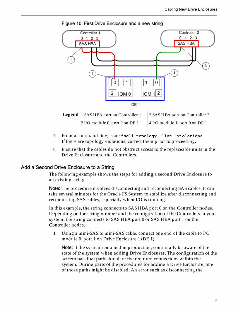
Figure 10: First Drive Enclosure and a new string
Legend 1 SAS HBA port on Controller 1 3 SAS HBA port on Controller 2
2 I/O module 0, port 0 on DE 1 4 I/O module 1, port 0 on DE 1
7 From a command line, issue fscli topology —list —violations.If there are topology violations, correct them prior to proceeding.
8 Ensure that the cables do not obstruct access to the replaceable units in theDrive Enclosure and the Controllers.
Add a Second Drive Enclosure to a StringThe following example shows the steps for adding a second Drive Enclosure toan existing string.
Note: The procedure involves disconnecting and reconnecting SAS cables. It cantake several minutes for the Oracle FS System to stabilize after disconnecting andreconnecting SAS cables, especially when I/O is running.
In this example, the string connects to SAS HBA port 0 on the Controller nodes.Depending on the string number and the configuration of the Controllers in yoursystem, the string connects to SAS HBA port 0 or SAS HBA port 1 on theController nodes.
1 Using a mini-SAS to mini-SAS cable, connect one end of the cable to I/Omodule 0, port 1 on Drive Enclosure 1 (DE 1).
Note: If the system remained in production, continually be aware of thestate of the system when adding Drive Enclosures. The configuration of thesystem has dual paths for all of the required connections within thesystem. During parts of the procedures for adding a Drive Enclosure, oneof those paths might be disabled. An error such as disconnecting the
Cabling New Drive Enclosures
37
wrong cable can cause serious problems to ongoing operation of thesystem.
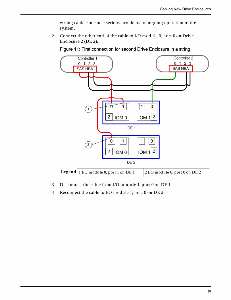
2 Connect the other end of the cable to I/O module 0, port 0 on DriveEnclosure 2 (DE 2).
Figure 11: First connection for second Drive Enclosure in a string
Legend 1 I/O module 0, port 1 on DE 1 2 I/O module 0, port 0 on DE 2
3 Disconnect the cable from I/O module 1, port 0 on DE 1.
4 Reconnect the cable to I/O module 1, port 0 on DE 2.
Cabling New Drive Enclosures
38
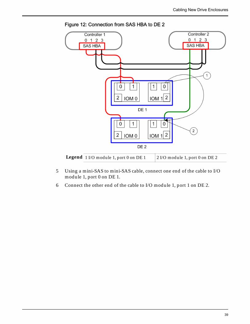
Figure 12: Connection from SAS HBA to DE 2
Legend 1 I/O module 1, port 0 on DE 1 2 I/O module 1, port 0 on DE 2
5 Using a mini-SAS to mini-SAS cable, connect one end of the cable to I/Omodule 1, port 0 on DE 1.
6 Connect the other end of the cable to I/O module 1, port 1 on DE 2.
Cabling New Drive Enclosures
39
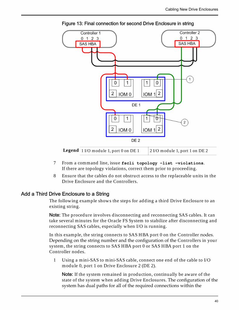
Figure 13: Final connection for second Drive Enclosure in string
Legend 1 I/O module 1, port 0 on DE 1 2 I/O module 1, port 1 on DE 2
7 From a command line, issue fscli topology —list —violations.If there are topology violations, correct them prior to proceeding.
8 Ensure that the cables do not obstruct access to the replaceable units in theDrive Enclosure and the Controllers.
Add a Third Drive Enclosure to a StringThe following example shows the steps for adding a third Drive Enclosure to anexisting string.
Note: The procedure involves disconnecting and reconnecting SAS cables. It cantake several minutes for the Oracle FS System to stabilize after disconnecting andreconnecting SAS cables, especially when I/O is running.
In this example, the string connects to SAS HBA port 0 on the Controller nodes.Depending on the string number and the configuration of the Controllers in yoursystem, the string connects to SAS HBA port 0 or SAS HBA port 1 on theController nodes.
1 Using a mini-SAS to mini-SAS cable, connect one end of the cable to I/Omodule 0, port 1 on Drive Enclosure 2 (DE 2).
Note: If the system remained in production, continually be aware of thestate of the system when adding Drive Enclosures. The configuration of thesystem has dual paths for all of the required connections within the
Cabling New Drive Enclosures
40
system. During parts of the procedures for adding a Drive Enclosure, oneof those paths might be disabled. An error such as disconnecting thewrong cable can cause serious problems to ongoing operation of thesystem.
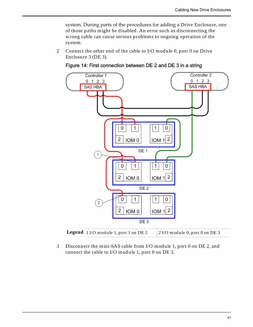
2 Connect the other end of the cable to I/O module 0, port 0 on DriveEnclosure 3 (DE 3).
Figure 14: First connection between DE 2 and DE 3 in a string
Legend 1 I/O module 1, port 1 on DE 2 2 I/O module 0, port 0 on DE 3
3 Disconnect the mini-SAS cable from I/O module 1, port 0 on DE 2, andconnect the cable to I/O module 1, port 0 on DE 3.
Cabling New Drive Enclosures
41
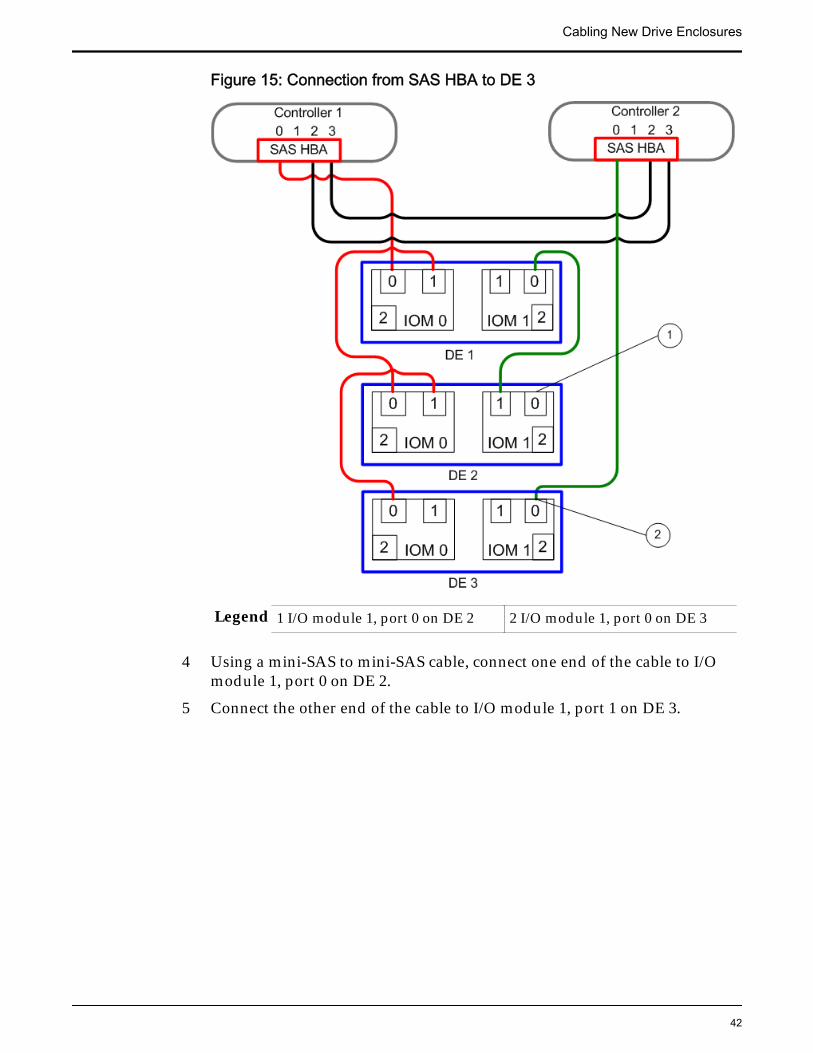
Figure 15: Connection from SAS HBA to DE 3
Legend 1 I/O module 1, port 0 on DE 2 2 I/O module 1, port 0 on DE 3
4 Using a mini-SAS to mini-SAS cable, connect one end of the cable to I/Omodule 1, port 0 on DE 2.
5 Connect the other end of the cable to I/O module 1, port 1 on DE 3.
Cabling New Drive Enclosures
42
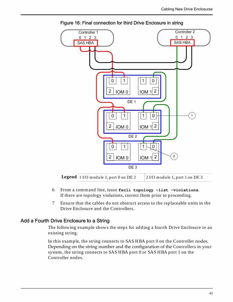
Figure 16: Final connection for third Drive Enclosure in string
Legend 1 I/O module 1, port 0 on DE 2 2 I/O module 1, port 1 on DE 3
6 From a command line, issue fscli topology —list —violations.If there are topology violations, correct them prior to proceeding.
7 Ensure that the cables do not obstruct access to the replaceable units in theDrive Enclosure and the Controllers.
Add a Fourth Drive Enclosure to a StringThe following example shows the steps for adding a fourth Drive Enclosure to anexisting string.
In this example, the string connects to SAS HBA port 0 on the Controller nodes.Depending on the string number and the configuration of the Controllers in yoursystem, the string connects to SAS HBA port 0 or SAS HBA port 1 on theController nodes.
Cabling New Drive Enclosures
43
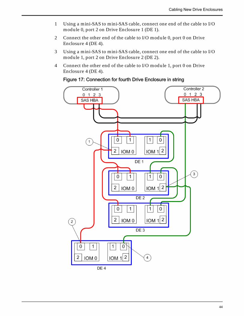
1 Using a mini-SAS to mini-SAS cable, connect one end of the cable to I/Omodule 0, port 2 on Drive Enclosure 1 (DE 1).
2 Connect the other end of the cable to I/O module 0, port 0 on DriveEnclosure 4 (DE 4).
3 Using a mini-SAS to mini-SAS cable, connect one end of the cable to I/Omodule 1, port 2 on Drive Enclosure 2 (DE 2).
4 Connect the other end of the cable to I/O module 1, port 0 on DriveEnclosure 4 (DE 4).
Figure 17: Connection for fourth Drive Enclosure in string
Cabling New Drive Enclosures
44
Legend 1 I/O module 0, port 2 on DE 1 3 I/O module 1, port 2 on DE 2
2 I/O module 0, port 0 on DE 4 4 I/O module 1, port 0 on DE 4
5 From a command line, issue fscli topology —list —violations.If there are topology violations, correct them prior to proceeding.
6 Ensure that the cables do not obstruct access to the replaceable units in theDrive Enclosure and the Controllers.
Add a Fifth Drive Enclosure to a StringThe following example shows the steps for adding a fifth Drive Enclosure to anexisting string.
In this example, the string connects to SAS HBA port 0 on the Controller nodes.Depending on the string number and the configuration of the Controllers in yoursystem, the string connects to SAS HBA port 0 or SAS HBA port 1 on theController nodes.
1 Using a mini-SAS to mini-SAS cable, connect one end of the cable to I/Omodule 0, port 2 on the third Drive Enclosure (DE 3) in the string.
2 Connect the other end of the cable to I/O module 0, port 0 on the fifth DriveEnclosure (DE 5).
3 Using a mini-SAS to mini-SAS cable, connect one end of the cable to I/Omodule 1, port 2 on DE 3.
4 Connect the other end of the cable to I/O module 1, port 0 on DE 5.
Cabling New Drive Enclosures
45
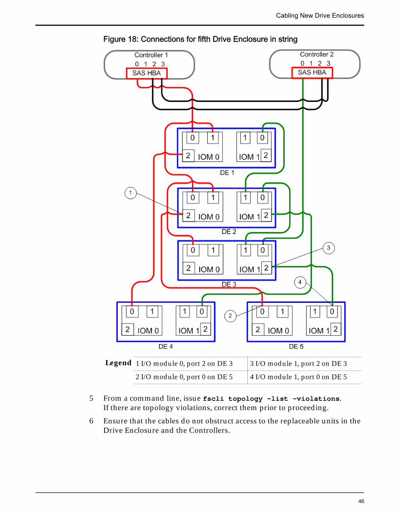
Figure 18: Connections for fifth Drive Enclosure in string
Legend 1 I/O module 0, port 2 on DE 3 3 I/O module 1, port 2 on DE 3
2 I/O module 0, port 0 on DE 5 4 I/O module 1, port 0 on DE 5
5 From a command line, issue fscli topology —list —violations.If there are topology violations, correct them prior to proceeding.
6 Ensure that the cables do not obstruct access to the replaceable units in theDrive Enclosure and the Controllers.
Cabling New Drive Enclosures
46

Complete the Expansion ProcessAfter cabling the new Drive Enclosures in the Oracle FS System, complete theexpansion process.
For more information involving the following steps, refer to Oracle Flash StorageSystem CLI Reference and Oracle Flash Storage System Administrator’s Guide.
1 If you brought the system offline during the add procedure, restart thesystem.
a) If you are using Oracle FS System Manager (GUI), select Oracle FS >Restart.
b) If you are using Oracle FS CLI (FSCLI), issue fscli system‑restart.
2 If the system remained in production during the add procedure, re-enableCall-Home events.
a) If you are using the GUI, navigate to System > Networking.
b) Select Actions > Modify > Notifications.
c) Select the Enable event triggered Call-Home check box and clickOK.
d) If you are using the FSCLI, issue fscli call_home ‑modify‑enableEventTrigger.
3 Accept the new drives into the system.If you are using the GUI, complete the following steps:
a) Navigate to System > Alerts and Events > System Alerts.
b) Double-click the Foreign Disk Drive system alert.
c) Click Accept New Drives.
d) Click OK.
The system updates the statuses of each new drive and automaticallycreates drive groups.
If you are using the FSCLI, complete the following steps:
a) Issue fscli system_alert –list –details to view the systemalert for foreign drives.
The alert displays the Drive Enclosure identifier and the foreigndrives.
b) Issue fscli enclosure ‑modify ‑enclosureenclosure‑id‑or‑fqn ‑acceptDrive drive‑slot‑number[, drive‑slot‑number]....
The system updates the statuses of each new drive and automaticallycreates drive groups.
Cabling New Drive Enclosures
47
4 Use the GUI to verify that the system discovers the newly added DriveEnclosures.
a) Navigate to System > Hardware > Drive Enclosures.
b) From the Drive Enclosures Overview page, monitor the status of thenew Drive Enclosures as the system discovers them.
Verify that each Drive Enclosure has a status of Normal and thedrive groups have a status of Unassigned.
5 As necessary, arrange the drive groups into the Storage Domains whereextra storage is needed.
For more information about managing drive groups and Storage Domains,refer to Oracle Flash Storage System Administrator’s Guide and Oracle FlashStorage System CLI Reference.
When a volume is created, it is possible that the Oracle FS System provisions thevolume across fewer drive groups than the optimal number that would satisfythe desired QoS settings for the volume. This situation can occur when aninsufficient number of drive groups are available in the Storage Domain in whichthe volume is created.
However, when Drive Enclosures are added to that Storage Domain and EnableAutomatic QoS Rebalancing is enabled, the Oracle FS System attempts to correctthe sub-optimal provisioning. The correction is accomplished by scanning for allvolumes that are sub-optimally provisioned in that Storage Domain.
If certain conditions exist, the system begins migrating the data for thosevolumes to the newly available drive groups that are provided by the new DriveEnclosures. The scanning and the migration depend on the Storage Class of eachvolume in the Storage Domain. The migration occurs only when sufficient freespace exists in the same Storage Class that is configured for the volume.
The QoS rebalance occurs during a daily scan; therefore, QoS rebalance mightnot happen for up to 24 hours. However, as drive groups are added, you canselect Rebalance Volume Data in the GUI or FSCLI to take advantage of the newstorage without waiting for the daily scan. The Rebalance Volume Data functiononly rebalances the volumes that are in the same Storage Classes as the newdrive groups and only if suboptimal volumes exist in the provisioning.
Related LinksPrepare the System for Cabling New Drive Enclosures
Cabling New Drive Enclosures
48
CHAPTER 5
Adding Solid State Drives
SSD Expansion KitsSolid state drives (SSDs) can be added to the Oracle FS System to expand thestorage pool. The SSD Expansion Kits provide SSDs, which are added to theDE2-24P Drive Enclosures configured with seven SSDs (400GB or 1.6TB) or 13SSDs (1.6TB).
The following types of SSDs are included in separate SSD Expansion Kits:
• Six disk performance SSDs (400GB)
• Six disk capacity SSDs (1.6TB)
Note: All of the SSDs within a Drive Enclosure must be the same capacity.
Add SSDs to a Drive EnclosureTo expand storage of an Oracle FS System, add SSDs to DE2-24P DriveEnclosures configured with SSDs.
Prerequisite: You have identified a DE2-24P Drive Enclosure with availableslots for adding the SSDs.
1 Unpack the SSD Expansion Kit.
2 Working with one SSD at a time, insert the SSDs into the available DriveEnclosure slots.
3 Accept the new drives into the system.If you are using the GUI, complete the following steps:
a) Navigate to System > Alerts and Events > System Alerts.
b) Double-click the Foreign Disk Drive system alert.
c) Click Accept New Drives.
d) Click OK.
The system updates the statuses of each new drive and automaticallycreates drive groups.
If you are using the FSCLI, complete the following steps:
a) Issue fscli system_alert –list –details to view the systemalert for foreign drives.
49
The alert displays the Drive Enclosure identifier and the foreigndrives.
b) Issue fscli enclosure ‑modify ‑enclosureenclosure‑id‑or‑fqn ‑acceptDrive drive‑slot‑number[, drive‑slot‑number]....
The system updates the statuses of each new drive and automaticallycreates drive groups.
4 As necessary, arrange the drive groups into the Storage Domains whereextra storage is needed.
For more information about managing drive groups and Storage Domains,refer to Oracle Flash Storage System Administrator’s Guide and Oracle FlashStorage System CLI Reference.
Adding Solid State Drives
50
APPENDIX A
SAS HBAs and String Configuration
Controller Connection Ports and String NumbersFactory configurations of the Oracle FS System adhere to specific connectionguidelines. In the factory configuration, Drive Enclosures are distributed amongall of the available strings. The number of available strings depends upon thenumber of SAS HBAs installed on the Controllers.
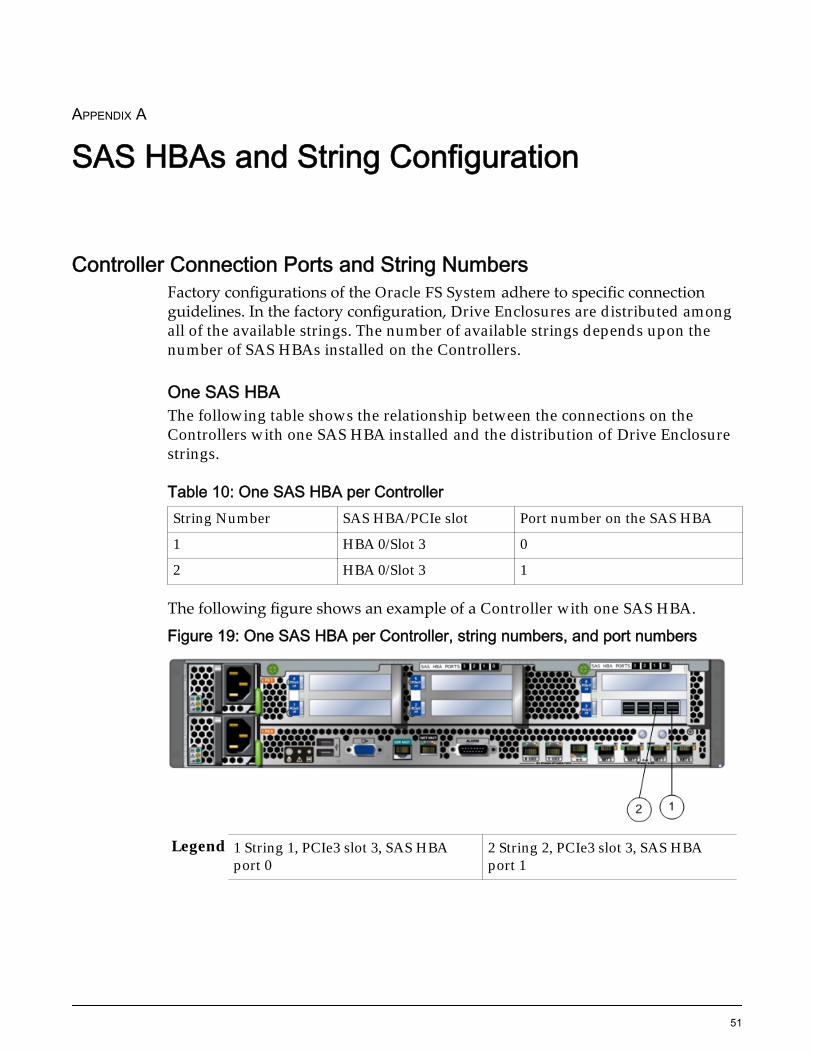
One SAS HBAThe following table shows the relationship between the connections on theControllers with one SAS HBA installed and the distribution of Drive Enclosurestrings.
Table 10: One SAS HBA per ControllerString Number SAS HBA/PCIe slot Port number on the SAS HBA
1 HBA 0/Slot 3 0
2 HBA 0/Slot 3 1
The following figure shows an example of a Controller with one SAS HBA.
Figure 19: One SAS HBA per Controller, string numbers, and port numbers
Legend 1 String 1, PCIe3 slot 3, SAS HBAport 0
2 String 2, PCIe3 slot 3, SAS HBAport 1
51
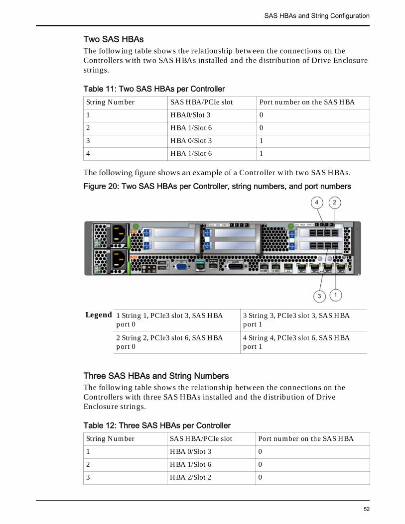
Two SAS HBAsThe following table shows the relationship between the connections on theControllers with two SAS HBAs installed and the distribution of Drive Enclosurestrings.
Table 11: Two SAS HBAs per ControllerString Number SAS HBA/PCIe slot Port number on the SAS HBA
1 HBA0/Slot 3 0
2 HBA 1/Slot 6 0
3 HBA 0/Slot 3 1
4 HBA 1/Slot 6 1
The following figure shows an example of a Controller with two SAS HBAs.
Figure 20: Two SAS HBAs per Controller, string numbers, and port numbers
Legend 1 String 1, PCIe3 slot 3, SAS HBAport 0
3 String 3, PCIe3 slot 3, SAS HBAport 1
2 String 2, PCIe3 slot 6, SAS HBAport 0
4 String 4, PCIe3 slot 6, SAS HBAport 1
Three SAS HBAs and String NumbersThe following table shows the relationship between the connections on theControllers with three SAS HBAs installed and the distribution of DriveEnclosure strings.
Table 12: Three SAS HBAs per ControllerString Number SAS HBA/PCIe slot Port number on the SAS HBA
1 HBA 0/Slot 3 0
2 HBA 1/Slot 6 0
3 HBA 2/Slot 2 0
SAS HBAs and String Configuration
52
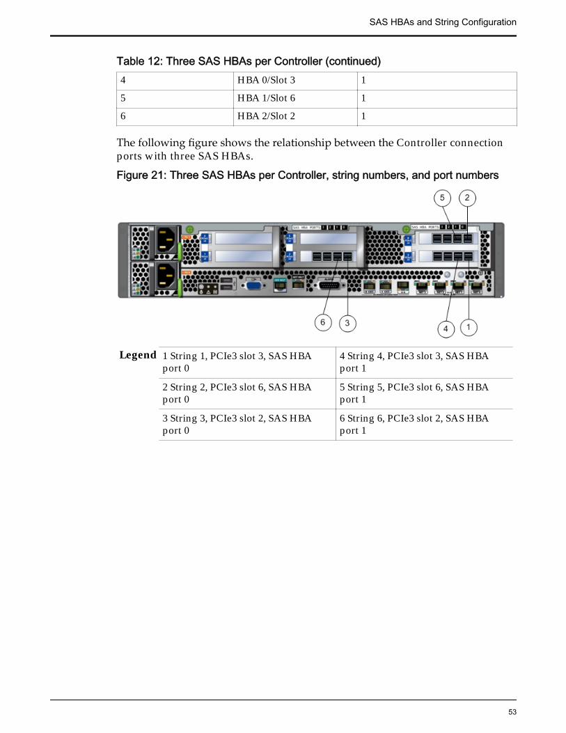
Table 12: Three SAS HBAs per Controller (continued)4 HBA 0/Slot 3 1
5 HBA 1/Slot 6 1
6 HBA 2/Slot 2 1
The following figure shows the relationship between the Controller connectionports with three SAS HBAs.
Figure 21: Three SAS HBAs per Controller, string numbers, and port numbers
Legend 1 String 1, PCIe3 slot 3, SAS HBAport 0
4 String 4, PCIe3 slot 3, SAS HBAport 1
2 String 2, PCIe3 slot 6, SAS HBAport 0
5 String 5, PCIe3 slot 6, SAS HBAport 1
3 String 3, PCIe3 slot 2, SAS HBAport 0
6 String 6, PCIe3 slot 2, SAS HBAport 1
SAS HBAs and String Configuration
53
APPENDIX B
Topology Output
Sample Topology OutputThe fscli topology -download -topoMap topomapfilename commandgenerates an output file that contains the connectivity maps of the Oracle FSSystem. Work with your Oracle Sales Engineer to analyze the connectivity map,verify the current topology of your system, and to determine where to add newDrive Enclosures for system expansion.
Annotated Samples of Topology Output (Performance System)The topology output file provides the following general information:
• Up to four connectivity maps generated at different times. The most recentconnectivity map is listed first in the output. In some cases, identical mapsmight be generated.
• Sections that clearly delineate the connectivity details for the Controllersand each Drive Enclosure in the system.
• The chassis IDs and the World Wide Node Names (WWN) of theControllers and the Drive Enclosures in the system. The chassis ID is thetwo-digit number displayed on the front of the chassis. The WWN is a 16-digit code that uniquely identifies each Controllerand Drive Enclosure.
• The connection entries indicate how each Controller HBA is connected tothe first Drive Enclosure of each string. The symbol <== ==> translates to“is connected to.” For example, /CONTROLLER-01 508002000158BF40 :HBA 0 : Port 0 <== ==> /ENCLOSURE-01 5080020001A9C9E5[5080020001B5D1FF]: IOM 0 : Port 0 translates to “Controller 01,HBA 0, port 0 is connected to DE-01, IOM 0, port 0.”
The following figure shows annotated details for the Controllers in the topologyoutput for a system configured with three SAS HBAs and 30 Drive Enclosures.
54
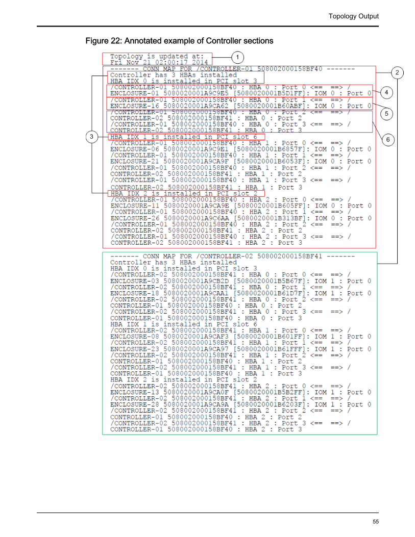
Figure 22: Annotated example of Controller sections
Topology Output
55
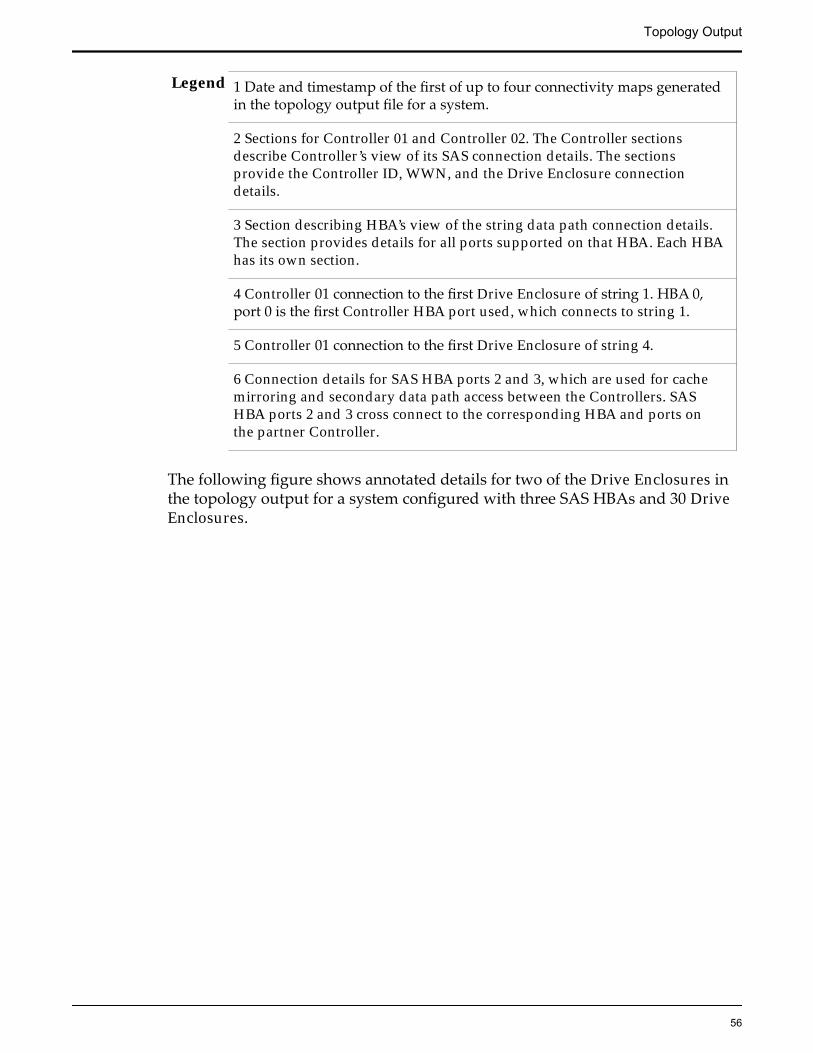
Legend 1 Date and timestamp of the first of up to four connectivity maps generatedin the topology output file for a system.
2 Sections for Controller 01 and Controller 02. The Controller sectionsdescribe Controller’s view of its SAS connection details. The sectionsprovide the Controller ID, WWN, and the Drive Enclosure connectiondetails.
3 Section describing HBA’s view of the string data path connection details.The section provides details for all ports supported on that HBA. Each HBAhas its own section.
4 Controller 01 connection to the first Drive Enclosure of string 1. HBA 0,port 0 is the first Controller HBA port used, which connects to string 1.
5 Controller 01 connection to the first Drive Enclosure of string 4.
6 Connection details for SAS HBA ports 2 and 3, which are used for cachemirroring and secondary data path access between the Controllers. SASHBA ports 2 and 3 cross connect to the corresponding HBA and ports onthe partner Controller.
The following figure shows annotated details for two of the Drive Enclosures inthe topology output for a system configured with three SAS HBAs and 30 DriveEnclosures.
Topology Output
56
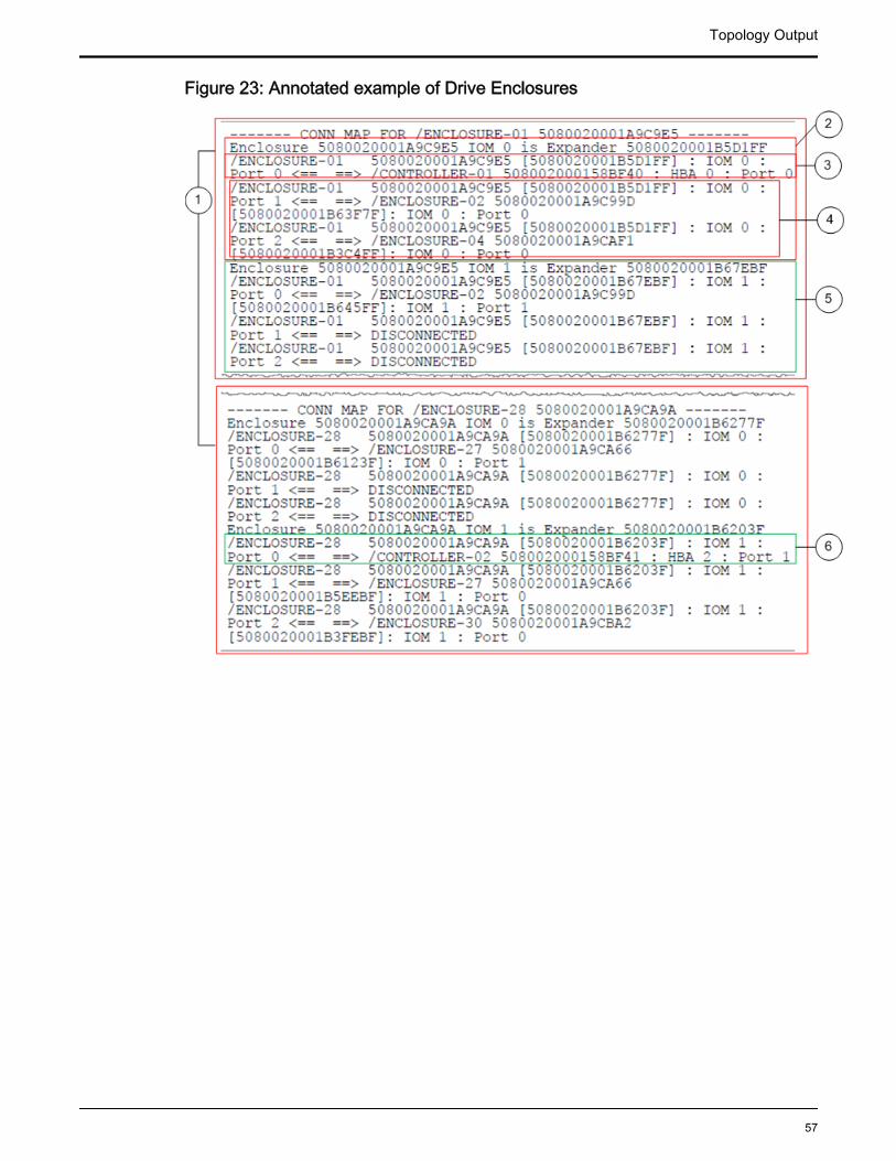
Figure 23: Annotated example of Drive Enclosures
Topology Output
57
Legend 1 Sections within the topology map that describe the data path connectionsfor each Drive Enclosure. Each section provides the chassis IDs, the WWN,and the port connection details for both I/O module 0 and I/O module 1.
2 Section describing the data path connections for I/O module 0 data pathconnections. The section provides the expander's unique ID and each portconnection for I/O module 0.
3 Section describing connection for I/O module 0, port 0. In this example, I/O module 0, port 0 connects to Controller 01, HBA 0, port 0. Theconnections should correspond with the Controller 01 entry in theController 01 section above
4 Section describing the connections on I/O module 0, port 1 and port 2.These are egress ports that connect to downstream Drive Enclosures withinthe string.
5 Section describing the connections on I/O module 1 of Drive Enclosure 01.
6 Drive Enclosure 28’s connection to Controller 02. In this example, DriveEnclosure 28 connects to HBA 2, port 1 on Controller 02, which makes it thethird Drive Enclosure within string 6. The connections should correspondwith the Controller 02 entry in the Controller 02 section above.
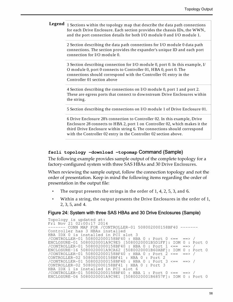
fscli topology –download –topomap Command (Sample)The following example provides sample output of the complete topology for afactory-configured system with three SAS HBAs and 30 Drive Enclosures.
When reviewing the sample output, follow the connection topology and not theorder of presentation. Keep in mind the following items regarding the order ofpresentation in the output file:
• The output presents the strings in the order of 1, 4, 2, 5, 3, and 6.
• Within a string, the output presents the Drive Enclosures in the order of 1,2, 3, 5, and 4.
Figure 24: System with three SAS HBAs and 30 Drive Enclosures (Sample)Topology is updated at:Fri Nov 21 02:00:17 2014------- CONN MAP FOR /CONTROLLER-01 508002000158BF40 -------Controller has 3 HBAs installedHBA IDX 0 is installed in PCI slot 3/CONTROLLER-01 508002000158BF40 : HBA 0 : Port 0 <== ==> /ENCLOSURE-01 5080020001A9C9E5 [5080020001B5D1FF]: IOM 0 : Port 0/CONTROLLER-01 508002000158BF40 : HBA 0 : Port 1 <== ==> /ENCLOSURE-16 5080020001A9CA62 [5080020001B60ABF]: IOM 0 : Port 0/CONTROLLER-01 508002000158BF40 : HBA 0 : Port 2 <== ==> /CONTROLLER-02 508002000158BF41 : HBA 0 : Port 2/CONTROLLER-01 508002000158BF40 : HBA 0 : Port 3 <== ==> /CONTROLLER-02 508002000158BF41 : HBA 0 : Port 3HBA IDX 1 is installed in PCI slot 6/CONTROLLER-01 508002000158BF40 : HBA 1 : Port 0 <== ==> /ENCLOSURE-06 5080020001A9C9E1 [5080020001B6857F]: IOM 0 : Port 0
Topology Output
58
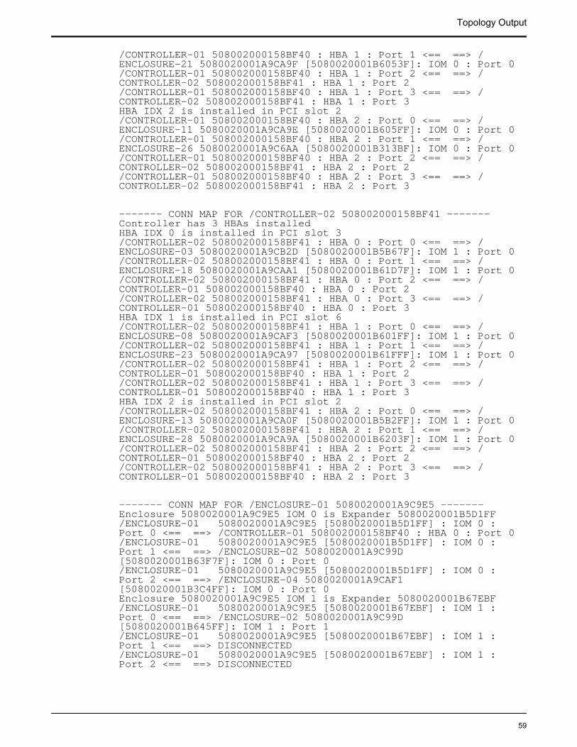
/CONTROLLER-01 508002000158BF40 : HBA 1 : Port 1 <== ==> /ENCLOSURE-21 5080020001A9CA9F [5080020001B6053F]: IOM 0 : Port 0/CONTROLLER-01 508002000158BF40 : HBA 1 : Port 2 <== ==> /CONTROLLER-02 508002000158BF41 : HBA 1 : Port 2/CONTROLLER-01 508002000158BF40 : HBA 1 : Port 3 <== ==> /CONTROLLER-02 508002000158BF41 : HBA 1 : Port 3HBA IDX 2 is installed in PCI slot 2/CONTROLLER-01 508002000158BF40 : HBA 2 : Port 0 <== ==> /ENCLOSURE-11 5080020001A9CA9E [5080020001B605FF]: IOM 0 : Port 0/CONTROLLER-01 508002000158BF40 : HBA 2 : Port 1 <== ==> /ENCLOSURE-26 5080020001A9C6AA [5080020001B313BF]: IOM 0 : Port 0/CONTROLLER-01 508002000158BF40 : HBA 2 : Port 2 <== ==> /CONTROLLER-02 508002000158BF41 : HBA 2 : Port 2/CONTROLLER-01 508002000158BF40 : HBA 2 : Port 3 <== ==> /CONTROLLER-02 508002000158BF41 : HBA 2 : Port 3
------- CONN MAP FOR /CONTROLLER-02 508002000158BF41 -------Controller has 3 HBAs installedHBA IDX 0 is installed in PCI slot 3/CONTROLLER-02 508002000158BF41 : HBA 0 : Port 0 <== ==> /ENCLOSURE-03 5080020001A9CB2D [5080020001B5B67F]: IOM 1 : Port 0/CONTROLLER-02 508002000158BF41 : HBA 0 : Port 1 <== ==> /ENCLOSURE-18 5080020001A9CAA1 [5080020001B61D7F]: IOM 1 : Port 0/CONTROLLER-02 508002000158BF41 : HBA 0 : Port 2 <== ==> /CONTROLLER-01 508002000158BF40 : HBA 0 : Port 2/CONTROLLER-02 508002000158BF41 : HBA 0 : Port 3 <== ==> /CONTROLLER-01 508002000158BF40 : HBA 0 : Port 3HBA IDX 1 is installed in PCI slot 6/CONTROLLER-02 508002000158BF41 : HBA 1 : Port 0 <== ==> /ENCLOSURE-08 5080020001A9CAF3 [5080020001B601FF]: IOM 1 : Port 0/CONTROLLER-02 508002000158BF41 : HBA 1 : Port 1 <== ==> /ENCLOSURE-23 5080020001A9CA97 [5080020001B61FFF]: IOM 1 : Port 0/CONTROLLER-02 508002000158BF41 : HBA 1 : Port 2 <== ==> /CONTROLLER-01 508002000158BF40 : HBA 1 : Port 2/CONTROLLER-02 508002000158BF41 : HBA 1 : Port 3 <== ==> /CONTROLLER-01 508002000158BF40 : HBA 1 : Port 3HBA IDX 2 is installed in PCI slot 2/CONTROLLER-02 508002000158BF41 : HBA 2 : Port 0 <== ==> /ENCLOSURE-13 5080020001A9CA0F [5080020001B5B2FF]: IOM 1 : Port 0/CONTROLLER-02 508002000158BF41 : HBA 2 : Port 1 <== ==> /ENCLOSURE-28 5080020001A9CA9A [5080020001B6203F]: IOM 1 : Port 0/CONTROLLER-02 508002000158BF41 : HBA 2 : Port 2 <== ==> /CONTROLLER-01 508002000158BF40 : HBA 2 : Port 2/CONTROLLER-02 508002000158BF41 : HBA 2 : Port 3 <== ==> /CONTROLLER-01 508002000158BF40 : HBA 2 : Port 3
------- CONN MAP FOR /ENCLOSURE-01 5080020001A9C9E5 -------Enclosure 5080020001A9C9E5 IOM 0 is Expander 5080020001B5D1FF/ENCLOSURE-01 5080020001A9C9E5 [5080020001B5D1FF] : IOM 0 : Port 0 <== ==> /CONTROLLER-01 508002000158BF40 : HBA 0 : Port 0/ENCLOSURE-01 5080020001A9C9E5 [5080020001B5D1FF] : IOM 0 : Port 1 <== ==> /ENCLOSURE-02 5080020001A9C99D [5080020001B63F7F]: IOM 0 : Port 0/ENCLOSURE-01 5080020001A9C9E5 [5080020001B5D1FF] : IOM 0 : Port 2 <== ==> /ENCLOSURE-04 5080020001A9CAF1 [5080020001B3C4FF]: IOM 0 : Port 0Enclosure 5080020001A9C9E5 IOM 1 is Expander 5080020001B67EBF/ENCLOSURE-01 5080020001A9C9E5 [5080020001B67EBF] : IOM 1 : Port 0 <== ==> /ENCLOSURE-02 5080020001A9C99D [5080020001B645FF]: IOM 1 : Port 1/ENCLOSURE-01 5080020001A9C9E5 [5080020001B67EBF] : IOM 1 : Port 1 <== ==> DISCONNECTED/ENCLOSURE-01 5080020001A9C9E5 [5080020001B67EBF] : IOM 1 : Port 2 <== ==> DISCONNECTED
Topology Output
59
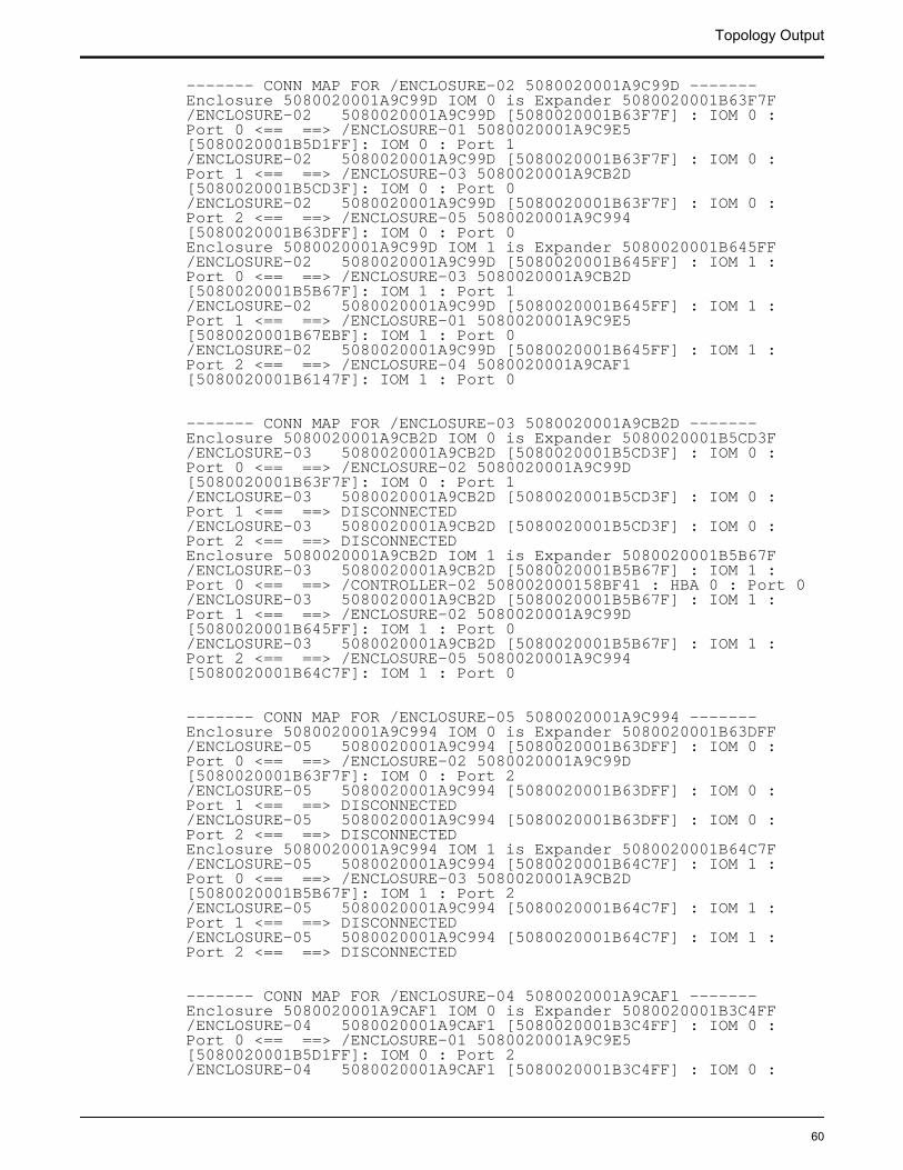
------- CONN MAP FOR /ENCLOSURE-02 5080020001A9C99D -------Enclosure 5080020001A9C99D IOM 0 is Expander 5080020001B63F7F/ENCLOSURE-02 5080020001A9C99D [5080020001B63F7F] : IOM 0 : Port 0 <== ==> /ENCLOSURE-01 5080020001A9C9E5 [5080020001B5D1FF]: IOM 0 : Port 1/ENCLOSURE-02 5080020001A9C99D [5080020001B63F7F] : IOM 0 : Port 1 <== ==> /ENCLOSURE-03 5080020001A9CB2D [5080020001B5CD3F]: IOM 0 : Port 0/ENCLOSURE-02 5080020001A9C99D [5080020001B63F7F] : IOM 0 : Port 2 <== ==> /ENCLOSURE-05 5080020001A9C994 [5080020001B63DFF]: IOM 0 : Port 0Enclosure 5080020001A9C99D IOM 1 is Expander 5080020001B645FF/ENCLOSURE-02 5080020001A9C99D [5080020001B645FF] : IOM 1 : Port 0 <== ==> /ENCLOSURE-03 5080020001A9CB2D [5080020001B5B67F]: IOM 1 : Port 1/ENCLOSURE-02 5080020001A9C99D [5080020001B645FF] : IOM 1 : Port 1 <== ==> /ENCLOSURE-01 5080020001A9C9E5 [5080020001B67EBF]: IOM 1 : Port 0/ENCLOSURE-02 5080020001A9C99D [5080020001B645FF] : IOM 1 : Port 2 <== ==> /ENCLOSURE-04 5080020001A9CAF1 [5080020001B6147F]: IOM 1 : Port 0
------- CONN MAP FOR /ENCLOSURE-03 5080020001A9CB2D -------Enclosure 5080020001A9CB2D IOM 0 is Expander 5080020001B5CD3F/ENCLOSURE-03 5080020001A9CB2D [5080020001B5CD3F] : IOM 0 : Port 0 <== ==> /ENCLOSURE-02 5080020001A9C99D [5080020001B63F7F]: IOM 0 : Port 1/ENCLOSURE-03 5080020001A9CB2D [5080020001B5CD3F] : IOM 0 : Port 1 <== ==> DISCONNECTED/ENCLOSURE-03 5080020001A9CB2D [5080020001B5CD3F] : IOM 0 : Port 2 <== ==> DISCONNECTEDEnclosure 5080020001A9CB2D IOM 1 is Expander 5080020001B5B67F/ENCLOSURE-03 5080020001A9CB2D [5080020001B5B67F] : IOM 1 : Port 0 <== ==> /CONTROLLER-02 508002000158BF41 : HBA 0 : Port 0/ENCLOSURE-03 5080020001A9CB2D [5080020001B5B67F] : IOM 1 : Port 1 <== ==> /ENCLOSURE-02 5080020001A9C99D [5080020001B645FF]: IOM 1 : Port 0/ENCLOSURE-03 5080020001A9CB2D [5080020001B5B67F] : IOM 1 : Port 2 <== ==> /ENCLOSURE-05 5080020001A9C994 [5080020001B64C7F]: IOM 1 : Port 0
------- CONN MAP FOR /ENCLOSURE-05 5080020001A9C994 -------Enclosure 5080020001A9C994 IOM 0 is Expander 5080020001B63DFF/ENCLOSURE-05 5080020001A9C994 [5080020001B63DFF] : IOM 0 : Port 0 <== ==> /ENCLOSURE-02 5080020001A9C99D [5080020001B63F7F]: IOM 0 : Port 2/ENCLOSURE-05 5080020001A9C994 [5080020001B63DFF] : IOM 0 : Port 1 <== ==> DISCONNECTED/ENCLOSURE-05 5080020001A9C994 [5080020001B63DFF] : IOM 0 : Port 2 <== ==> DISCONNECTEDEnclosure 5080020001A9C994 IOM 1 is Expander 5080020001B64C7F/ENCLOSURE-05 5080020001A9C994 [5080020001B64C7F] : IOM 1 : Port 0 <== ==> /ENCLOSURE-03 5080020001A9CB2D [5080020001B5B67F]: IOM 1 : Port 2/ENCLOSURE-05 5080020001A9C994 [5080020001B64C7F] : IOM 1 : Port 1 <== ==> DISCONNECTED/ENCLOSURE-05 5080020001A9C994 [5080020001B64C7F] : IOM 1 : Port 2 <== ==> DISCONNECTED
------- CONN MAP FOR /ENCLOSURE-04 5080020001A9CAF1 -------Enclosure 5080020001A9CAF1 IOM 0 is Expander 5080020001B3C4FF/ENCLOSURE-04 5080020001A9CAF1 [5080020001B3C4FF] : IOM 0 : Port 0 <== ==> /ENCLOSURE-01 5080020001A9C9E5 [5080020001B5D1FF]: IOM 0 : Port 2/ENCLOSURE-04 5080020001A9CAF1 [5080020001B3C4FF] : IOM 0 :
Topology Output
60
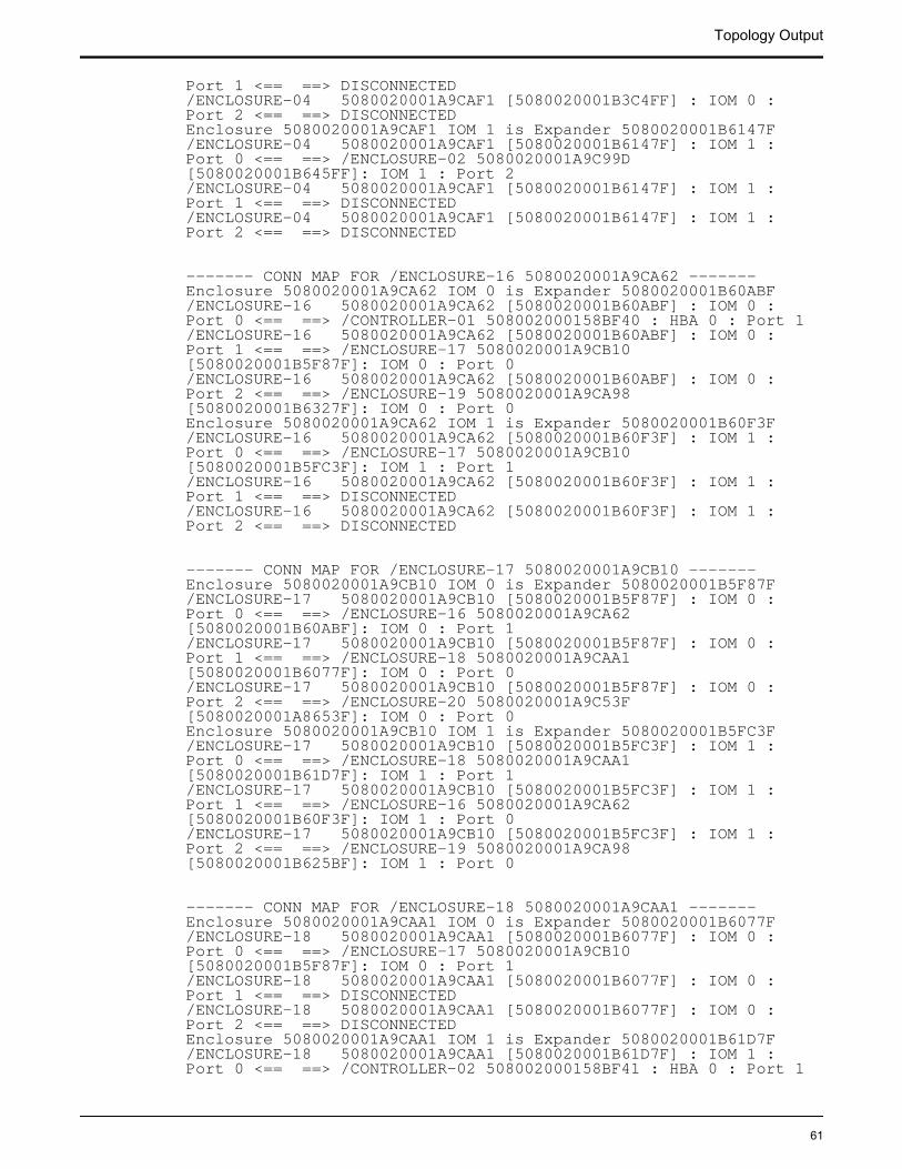
Port 1 <== ==> DISCONNECTED/ENCLOSURE-04 5080020001A9CAF1 [5080020001B3C4FF] : IOM 0 : Port 2 <== ==> DISCONNECTEDEnclosure 5080020001A9CAF1 IOM 1 is Expander 5080020001B6147F/ENCLOSURE-04 5080020001A9CAF1 [5080020001B6147F] : IOM 1 : Port 0 <== ==> /ENCLOSURE-02 5080020001A9C99D [5080020001B645FF]: IOM 1 : Port 2/ENCLOSURE-04 5080020001A9CAF1 [5080020001B6147F] : IOM 1 : Port 1 <== ==> DISCONNECTED/ENCLOSURE-04 5080020001A9CAF1 [5080020001B6147F] : IOM 1 : Port 2 <== ==> DISCONNECTED
------- CONN MAP FOR /ENCLOSURE-16 5080020001A9CA62 -------Enclosure 5080020001A9CA62 IOM 0 is Expander 5080020001B60ABF/ENCLOSURE-16 5080020001A9CA62 [5080020001B60ABF] : IOM 0 : Port 0 <== ==> /CONTROLLER-01 508002000158BF40 : HBA 0 : Port 1/ENCLOSURE-16 5080020001A9CA62 [5080020001B60ABF] : IOM 0 : Port 1 <== ==> /ENCLOSURE-17 5080020001A9CB10 [5080020001B5F87F]: IOM 0 : Port 0/ENCLOSURE-16 5080020001A9CA62 [5080020001B60ABF] : IOM 0 : Port 2 <== ==> /ENCLOSURE-19 5080020001A9CA98 [5080020001B6327F]: IOM 0 : Port 0Enclosure 5080020001A9CA62 IOM 1 is Expander 5080020001B60F3F/ENCLOSURE-16 5080020001A9CA62 [5080020001B60F3F] : IOM 1 : Port 0 <== ==> /ENCLOSURE-17 5080020001A9CB10 [5080020001B5FC3F]: IOM 1 : Port 1/ENCLOSURE-16 5080020001A9CA62 [5080020001B60F3F] : IOM 1 : Port 1 <== ==> DISCONNECTED/ENCLOSURE-16 5080020001A9CA62 [5080020001B60F3F] : IOM 1 : Port 2 <== ==> DISCONNECTED
------- CONN MAP FOR /ENCLOSURE-17 5080020001A9CB10 -------Enclosure 5080020001A9CB10 IOM 0 is Expander 5080020001B5F87F/ENCLOSURE-17 5080020001A9CB10 [5080020001B5F87F] : IOM 0 : Port 0 <== ==> /ENCLOSURE-16 5080020001A9CA62 [5080020001B60ABF]: IOM 0 : Port 1/ENCLOSURE-17 5080020001A9CB10 [5080020001B5F87F] : IOM 0 : Port 1 <== ==> /ENCLOSURE-18 5080020001A9CAA1 [5080020001B6077F]: IOM 0 : Port 0/ENCLOSURE-17 5080020001A9CB10 [5080020001B5F87F] : IOM 0 : Port 2 <== ==> /ENCLOSURE-20 5080020001A9C53F [5080020001A8653F]: IOM 0 : Port 0Enclosure 5080020001A9CB10 IOM 1 is Expander 5080020001B5FC3F/ENCLOSURE-17 5080020001A9CB10 [5080020001B5FC3F] : IOM 1 : Port 0 <== ==> /ENCLOSURE-18 5080020001A9CAA1 [5080020001B61D7F]: IOM 1 : Port 1/ENCLOSURE-17 5080020001A9CB10 [5080020001B5FC3F] : IOM 1 : Port 1 <== ==> /ENCLOSURE-16 5080020001A9CA62 [5080020001B60F3F]: IOM 1 : Port 0/ENCLOSURE-17 5080020001A9CB10 [5080020001B5FC3F] : IOM 1 : Port 2 <== ==> /ENCLOSURE-19 5080020001A9CA98 [5080020001B625BF]: IOM 1 : Port 0
------- CONN MAP FOR /ENCLOSURE-18 5080020001A9CAA1 -------Enclosure 5080020001A9CAA1 IOM 0 is Expander 5080020001B6077F/ENCLOSURE-18 5080020001A9CAA1 [5080020001B6077F] : IOM 0 : Port 0 <== ==> /ENCLOSURE-17 5080020001A9CB10 [5080020001B5F87F]: IOM 0 : Port 1/ENCLOSURE-18 5080020001A9CAA1 [5080020001B6077F] : IOM 0 : Port 1 <== ==> DISCONNECTED/ENCLOSURE-18 5080020001A9CAA1 [5080020001B6077F] : IOM 0 : Port 2 <== ==> DISCONNECTEDEnclosure 5080020001A9CAA1 IOM 1 is Expander 5080020001B61D7F/ENCLOSURE-18 5080020001A9CAA1 [5080020001B61D7F] : IOM 1 : Port 0 <== ==> /CONTROLLER-02 508002000158BF41 : HBA 0 : Port 1
Topology Output
61
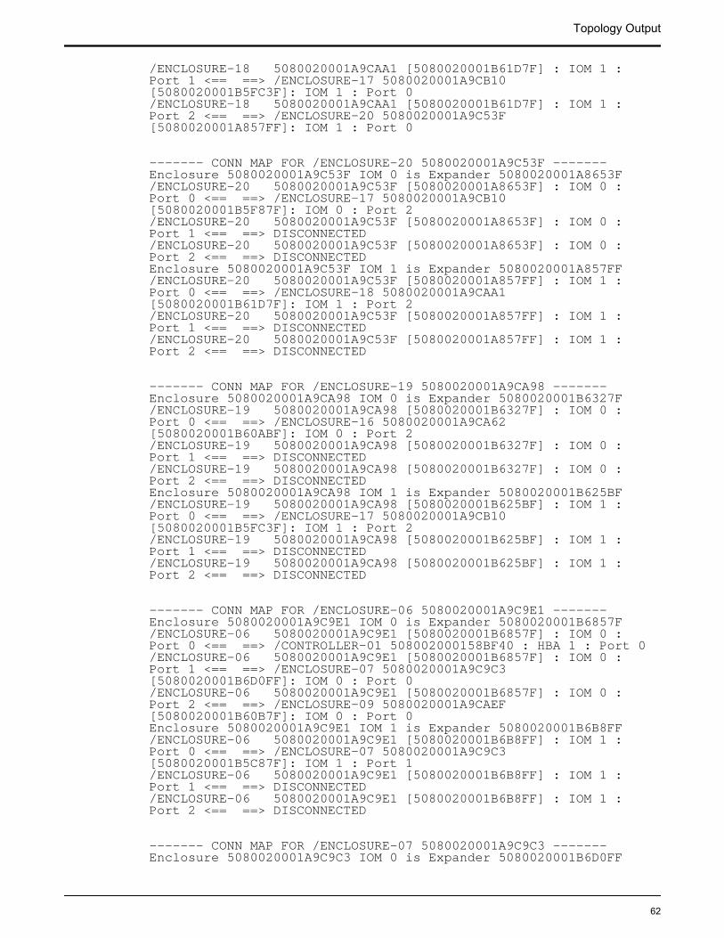
/ENCLOSURE-18 5080020001A9CAA1 [5080020001B61D7F] : IOM 1 : Port 1 <== ==> /ENCLOSURE-17 5080020001A9CB10 [5080020001B5FC3F]: IOM 1 : Port 0/ENCLOSURE-18 5080020001A9CAA1 [5080020001B61D7F] : IOM 1 : Port 2 <== ==> /ENCLOSURE-20 5080020001A9C53F [5080020001A857FF]: IOM 1 : Port 0
------- CONN MAP FOR /ENCLOSURE-20 5080020001A9C53F -------Enclosure 5080020001A9C53F IOM 0 is Expander 5080020001A8653F/ENCLOSURE-20 5080020001A9C53F [5080020001A8653F] : IOM 0 : Port 0 <== ==> /ENCLOSURE-17 5080020001A9CB10 [5080020001B5F87F]: IOM 0 : Port 2/ENCLOSURE-20 5080020001A9C53F [5080020001A8653F] : IOM 0 : Port 1 <== ==> DISCONNECTED/ENCLOSURE-20 5080020001A9C53F [5080020001A8653F] : IOM 0 : Port 2 <== ==> DISCONNECTEDEnclosure 5080020001A9C53F IOM 1 is Expander 5080020001A857FF/ENCLOSURE-20 5080020001A9C53F [5080020001A857FF] : IOM 1 : Port 0 <== ==> /ENCLOSURE-18 5080020001A9CAA1 [5080020001B61D7F]: IOM 1 : Port 2/ENCLOSURE-20 5080020001A9C53F [5080020001A857FF] : IOM 1 : Port 1 <== ==> DISCONNECTED/ENCLOSURE-20 5080020001A9C53F [5080020001A857FF] : IOM 1 : Port 2 <== ==> DISCONNECTED
------- CONN MAP FOR /ENCLOSURE-19 5080020001A9CA98 -------Enclosure 5080020001A9CA98 IOM 0 is Expander 5080020001B6327F/ENCLOSURE-19 5080020001A9CA98 [5080020001B6327F] : IOM 0 : Port 0 <== ==> /ENCLOSURE-16 5080020001A9CA62 [5080020001B60ABF]: IOM 0 : Port 2/ENCLOSURE-19 5080020001A9CA98 [5080020001B6327F] : IOM 0 : Port 1 <== ==> DISCONNECTED/ENCLOSURE-19 5080020001A9CA98 [5080020001B6327F] : IOM 0 : Port 2 <== ==> DISCONNECTEDEnclosure 5080020001A9CA98 IOM 1 is Expander 5080020001B625BF/ENCLOSURE-19 5080020001A9CA98 [5080020001B625BF] : IOM 1 : Port 0 <== ==> /ENCLOSURE-17 5080020001A9CB10 [5080020001B5FC3F]: IOM 1 : Port 2/ENCLOSURE-19 5080020001A9CA98 [5080020001B625BF] : IOM 1 : Port 1 <== ==> DISCONNECTED/ENCLOSURE-19 5080020001A9CA98 [5080020001B625BF] : IOM 1 : Port 2 <== ==> DISCONNECTED
------- CONN MAP FOR /ENCLOSURE-06 5080020001A9C9E1 -------Enclosure 5080020001A9C9E1 IOM 0 is Expander 5080020001B6857F/ENCLOSURE-06 5080020001A9C9E1 [5080020001B6857F] : IOM 0 : Port 0 <== ==> /CONTROLLER-01 508002000158BF40 : HBA 1 : Port 0/ENCLOSURE-06 5080020001A9C9E1 [5080020001B6857F] : IOM 0 : Port 1 <== ==> /ENCLOSURE-07 5080020001A9C9C3 [5080020001B6D0FF]: IOM 0 : Port 0/ENCLOSURE-06 5080020001A9C9E1 [5080020001B6857F] : IOM 0 : Port 2 <== ==> /ENCLOSURE-09 5080020001A9CAEF [5080020001B60B7F]: IOM 0 : Port 0Enclosure 5080020001A9C9E1 IOM 1 is Expander 5080020001B6B8FF/ENCLOSURE-06 5080020001A9C9E1 [5080020001B6B8FF] : IOM 1 : Port 0 <== ==> /ENCLOSURE-07 5080020001A9C9C3 [5080020001B5C87F]: IOM 1 : Port 1/ENCLOSURE-06 5080020001A9C9E1 [5080020001B6B8FF] : IOM 1 : Port 1 <== ==> DISCONNECTED/ENCLOSURE-06 5080020001A9C9E1 [5080020001B6B8FF] : IOM 1 : Port 2 <== ==> DISCONNECTED
------- CONN MAP FOR /ENCLOSURE-07 5080020001A9C9C3 -------Enclosure 5080020001A9C9C3 IOM 0 is Expander 5080020001B6D0FF
Topology Output
62
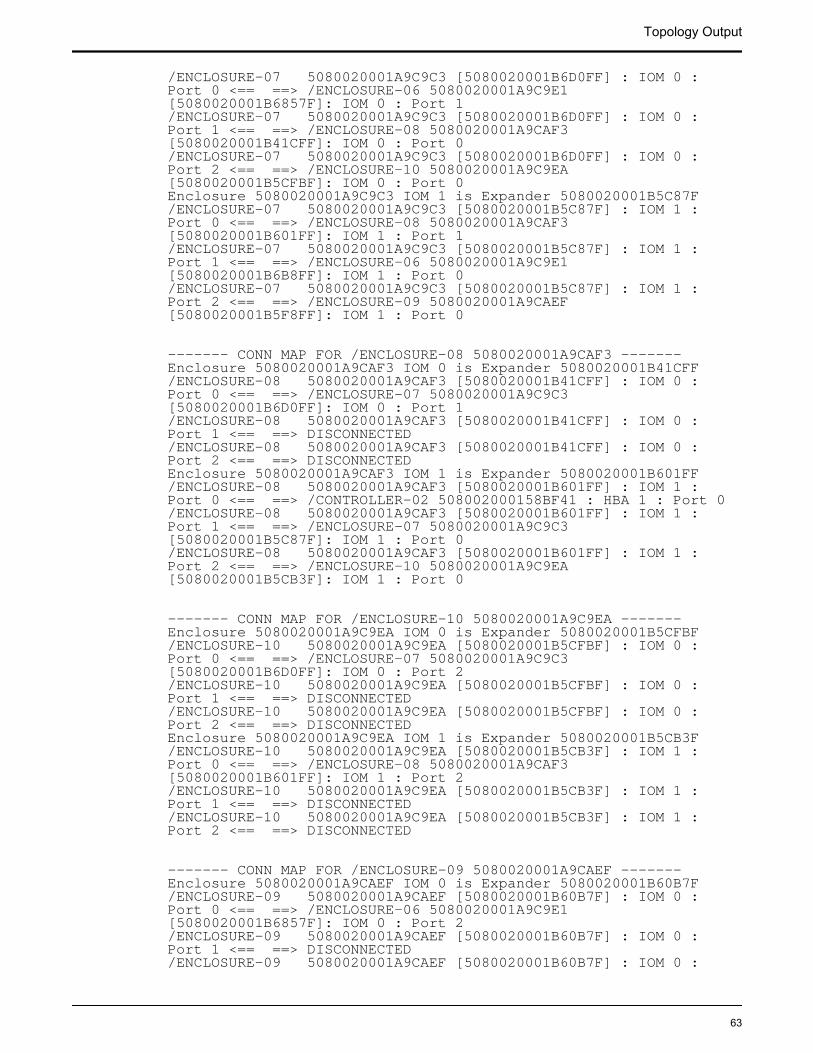
/ENCLOSURE-07 5080020001A9C9C3 [5080020001B6D0FF] : IOM 0 : Port 0 <== ==> /ENCLOSURE-06 5080020001A9C9E1 [5080020001B6857F]: IOM 0 : Port 1/ENCLOSURE-07 5080020001A9C9C3 [5080020001B6D0FF] : IOM 0 : Port 1 <== ==> /ENCLOSURE-08 5080020001A9CAF3 [5080020001B41CFF]: IOM 0 : Port 0/ENCLOSURE-07 5080020001A9C9C3 [5080020001B6D0FF] : IOM 0 : Port 2 <== ==> /ENCLOSURE-10 5080020001A9C9EA [5080020001B5CFBF]: IOM 0 : Port 0Enclosure 5080020001A9C9C3 IOM 1 is Expander 5080020001B5C87F/ENCLOSURE-07 5080020001A9C9C3 [5080020001B5C87F] : IOM 1 : Port 0 <== ==> /ENCLOSURE-08 5080020001A9CAF3 [5080020001B601FF]: IOM 1 : Port 1/ENCLOSURE-07 5080020001A9C9C3 [5080020001B5C87F] : IOM 1 : Port 1 <== ==> /ENCLOSURE-06 5080020001A9C9E1 [5080020001B6B8FF]: IOM 1 : Port 0/ENCLOSURE-07 5080020001A9C9C3 [5080020001B5C87F] : IOM 1 : Port 2 <== ==> /ENCLOSURE-09 5080020001A9CAEF [5080020001B5F8FF]: IOM 1 : Port 0
------- CONN MAP FOR /ENCLOSURE-08 5080020001A9CAF3 -------Enclosure 5080020001A9CAF3 IOM 0 is Expander 5080020001B41CFF/ENCLOSURE-08 5080020001A9CAF3 [5080020001B41CFF] : IOM 0 : Port 0 <== ==> /ENCLOSURE-07 5080020001A9C9C3 [5080020001B6D0FF]: IOM 0 : Port 1/ENCLOSURE-08 5080020001A9CAF3 [5080020001B41CFF] : IOM 0 : Port 1 <== ==> DISCONNECTED/ENCLOSURE-08 5080020001A9CAF3 [5080020001B41CFF] : IOM 0 : Port 2 <== ==> DISCONNECTEDEnclosure 5080020001A9CAF3 IOM 1 is Expander 5080020001B601FF/ENCLOSURE-08 5080020001A9CAF3 [5080020001B601FF] : IOM 1 : Port 0 <== ==> /CONTROLLER-02 508002000158BF41 : HBA 1 : Port 0/ENCLOSURE-08 5080020001A9CAF3 [5080020001B601FF] : IOM 1 : Port 1 <== ==> /ENCLOSURE-07 5080020001A9C9C3 [5080020001B5C87F]: IOM 1 : Port 0/ENCLOSURE-08 5080020001A9CAF3 [5080020001B601FF] : IOM 1 : Port 2 <== ==> /ENCLOSURE-10 5080020001A9C9EA [5080020001B5CB3F]: IOM 1 : Port 0
------- CONN MAP FOR /ENCLOSURE-10 5080020001A9C9EA -------Enclosure 5080020001A9C9EA IOM 0 is Expander 5080020001B5CFBF/ENCLOSURE-10 5080020001A9C9EA [5080020001B5CFBF] : IOM 0 : Port 0 <== ==> /ENCLOSURE-07 5080020001A9C9C3 [5080020001B6D0FF]: IOM 0 : Port 2/ENCLOSURE-10 5080020001A9C9EA [5080020001B5CFBF] : IOM 0 : Port 1 <== ==> DISCONNECTED/ENCLOSURE-10 5080020001A9C9EA [5080020001B5CFBF] : IOM 0 : Port 2 <== ==> DISCONNECTEDEnclosure 5080020001A9C9EA IOM 1 is Expander 5080020001B5CB3F/ENCLOSURE-10 5080020001A9C9EA [5080020001B5CB3F] : IOM 1 : Port 0 <== ==> /ENCLOSURE-08 5080020001A9CAF3 [5080020001B601FF]: IOM 1 : Port 2/ENCLOSURE-10 5080020001A9C9EA [5080020001B5CB3F] : IOM 1 : Port 1 <== ==> DISCONNECTED/ENCLOSURE-10 5080020001A9C9EA [5080020001B5CB3F] : IOM 1 : Port 2 <== ==> DISCONNECTED
------- CONN MAP FOR /ENCLOSURE-09 5080020001A9CAEF -------Enclosure 5080020001A9CAEF IOM 0 is Expander 5080020001B60B7F/ENCLOSURE-09 5080020001A9CAEF [5080020001B60B7F] : IOM 0 : Port 0 <== ==> /ENCLOSURE-06 5080020001A9C9E1 [5080020001B6857F]: IOM 0 : Port 2/ENCLOSURE-09 5080020001A9CAEF [5080020001B60B7F] : IOM 0 : Port 1 <== ==> DISCONNECTED/ENCLOSURE-09 5080020001A9CAEF [5080020001B60B7F] : IOM 0 :
Topology Output
63
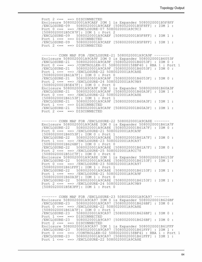
Port 2 <== ==> DISCONNECTEDEnclosure 5080020001A9CAEF IOM 1 is Expander 5080020001B5F8FF/ENCLOSURE-09 5080020001A9CAEF [5080020001B5F8FF] : IOM 1 : Port 0 <== ==> /ENCLOSURE-07 5080020001A9C9C3 [5080020001B5C87F]: IOM 1 : Port 2/ENCLOSURE-09 5080020001A9CAEF [5080020001B5F8FF] : IOM 1 : Port 1 <== ==> DISCONNECTED/ENCLOSURE-09 5080020001A9CAEF [5080020001B5F8FF] : IOM 1 : Port 2 <== ==> DISCONNECTED
------- CONN MAP FOR /ENCLOSURE-21 5080020001A9CA9F -------Enclosure 5080020001A9CA9F IOM 0 is Expander 5080020001B6053F/ENCLOSURE-21 5080020001A9CA9F [5080020001B6053F] : IOM 0 : Port 0 <== ==> /CONTROLLER-01 508002000158BF40 : HBA 1 : Port 1/ENCLOSURE-21 5080020001A9CA9F [5080020001B6053F] : IOM 0 : Port 1 <== ==> /ENCLOSURE-22 5080020001A9CA8E [5080020001B61A7F]: IOM 0 : Port 0/ENCLOSURE-21 5080020001A9CA9F [5080020001B6053F] : IOM 0 : Port 2 <== ==> /ENCLOSURE-24 5080020001A9C9B9 [5080020001B5E47F]: IOM 0 : Port 0Enclosure 5080020001A9CA9F IOM 1 is Expander 5080020001B60A3F/ENCLOSURE-21 5080020001A9CA9F [5080020001B60A3F] : IOM 1 : Port 0 <== ==> /ENCLOSURE-22 5080020001A9CA8E [5080020001B6153F]: IOM 1 : Port 1/ENCLOSURE-21 5080020001A9CA9F [5080020001B60A3F] : IOM 1 : Port 1 <== ==> DISCONNECTED/ENCLOSURE-21 5080020001A9CA9F [5080020001B60A3F] : IOM 1 : Port 2 <== ==> DISCONNECTED
------- CONN MAP FOR /ENCLOSURE-22 5080020001A9CA8E -------Enclosure 5080020001A9CA8E IOM 0 is Expander 5080020001B61A7F/ENCLOSURE-22 5080020001A9CA8E [5080020001B61A7F] : IOM 0 : Port 0 <== ==> /ENCLOSURE-21 5080020001A9CA9F [5080020001B6053F]: IOM 0 : Port 1/ENCLOSURE-22 5080020001A9CA8E [5080020001B61A7F] : IOM 0 : Port 1 <== ==> /ENCLOSURE-23 5080020001A9CA97 [5080020001B626BF]: IOM 0 : Port 0/ENCLOSURE-22 5080020001A9CA8E [5080020001B61A7F] : IOM 0 : Port 2 <== ==> /ENCLOSURE-25 5080020001A9CC78 [5080020001B51C7F]: IOM 0 : Port 0Enclosure 5080020001A9CA8E IOM 1 is Expander 5080020001B6153F/ENCLOSURE-22 5080020001A9CA8E [5080020001B6153F] : IOM 1 : Port 0 <== ==> /ENCLOSURE-23 5080020001A9CA97 [5080020001B61FFF]: IOM 1 : Port 1/ENCLOSURE-22 5080020001A9CA8E [5080020001B6153F] : IOM 1 : Port 1 <== ==> /ENCLOSURE-21 5080020001A9CA9F [5080020001B60A3F]: IOM 1 : Port 0/ENCLOSURE-22 5080020001A9CA8E [5080020001B6153F] : IOM 1 : Port 2 <== ==> /ENCLOSURE-24 5080020001A9C9B9 [5080020001B5E3FF]: IOM 1 : Port 0
------- CONN MAP FOR /ENCLOSURE-23 5080020001A9CA97 -------Enclosure 5080020001A9CA97 IOM 0 is Expander 5080020001B626BF/ENCLOSURE-23 5080020001A9CA97 [5080020001B626BF] : IOM 0 : Port 0 <== ==> /ENCLOSURE-22 5080020001A9CA8E [5080020001B61A7F]: IOM 0 : Port 1/ENCLOSURE-23 5080020001A9CA97 [5080020001B626BF] : IOM 0 : Port 1 <== ==> DISCONNECTED/ENCLOSURE-23 5080020001A9CA97 [5080020001B626BF] : IOM 0 : Port 2 <== ==> DISCONNECTEDEnclosure 5080020001A9CA97 IOM 1 is Expander 5080020001B61FFF/ENCLOSURE-23 5080020001A9CA97 [5080020001B61FFF] : IOM 1 : Port 0 <== ==> /CONTROLLER-02 508002000158BF41 : HBA 1 : Port 1/ENCLOSURE-23 5080020001A9CA97 [5080020001B61FFF] : IOM 1 : Port 1 <== ==> /ENCLOSURE-22 5080020001A9CA8E
Topology Output
64
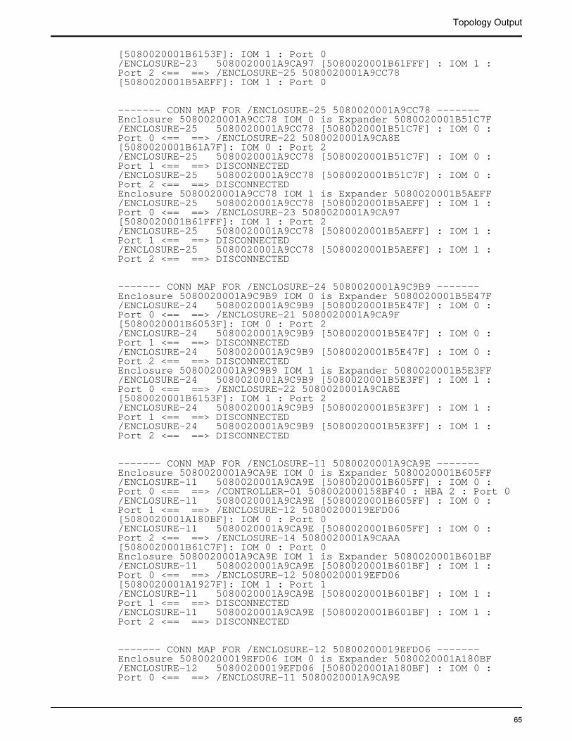
[5080020001B6153F]: IOM 1 : Port 0/ENCLOSURE-23 5080020001A9CA97 [5080020001B61FFF] : IOM 1 : Port 2 <== ==> /ENCLOSURE-25 5080020001A9CC78 [5080020001B5AEFF]: IOM 1 : Port 0
------- CONN MAP FOR /ENCLOSURE-25 5080020001A9CC78 -------Enclosure 5080020001A9CC78 IOM 0 is Expander 5080020001B51C7F/ENCLOSURE-25 5080020001A9CC78 [5080020001B51C7F] : IOM 0 : Port 0 <== ==> /ENCLOSURE-22 5080020001A9CA8E [5080020001B61A7F]: IOM 0 : Port 2/ENCLOSURE-25 5080020001A9CC78 [5080020001B51C7F] : IOM 0 : Port 1 <== ==> DISCONNECTED/ENCLOSURE-25 5080020001A9CC78 [5080020001B51C7F] : IOM 0 : Port 2 <== ==> DISCONNECTEDEnclosure 5080020001A9CC78 IOM 1 is Expander 5080020001B5AEFF/ENCLOSURE-25 5080020001A9CC78 [5080020001B5AEFF] : IOM 1 : Port 0 <== ==> /ENCLOSURE-23 5080020001A9CA97 [5080020001B61FFF]: IOM 1 : Port 2/ENCLOSURE-25 5080020001A9CC78 [5080020001B5AEFF] : IOM 1 : Port 1 <== ==> DISCONNECTED/ENCLOSURE-25 5080020001A9CC78 [5080020001B5AEFF] : IOM 1 : Port 2 <== ==> DISCONNECTED
------- CONN MAP FOR /ENCLOSURE-24 5080020001A9C9B9 -------Enclosure 5080020001A9C9B9 IOM 0 is Expander 5080020001B5E47F/ENCLOSURE-24 5080020001A9C9B9 [5080020001B5E47F] : IOM 0 : Port 0 <== ==> /ENCLOSURE-21 5080020001A9CA9F [5080020001B6053F]: IOM 0 : Port 2/ENCLOSURE-24 5080020001A9C9B9 [5080020001B5E47F] : IOM 0 : Port 1 <== ==> DISCONNECTED/ENCLOSURE-24 5080020001A9C9B9 [5080020001B5E47F] : IOM 0 : Port 2 <== ==> DISCONNECTEDEnclosure 5080020001A9C9B9 IOM 1 is Expander 5080020001B5E3FF/ENCLOSURE-24 5080020001A9C9B9 [5080020001B5E3FF] : IOM 1 : Port 0 <== ==> /ENCLOSURE-22 5080020001A9CA8E [5080020001B6153F]: IOM 1 : Port 2/ENCLOSURE-24 5080020001A9C9B9 [5080020001B5E3FF] : IOM 1 : Port 1 <== ==> DISCONNECTED/ENCLOSURE-24 5080020001A9C9B9 [5080020001B5E3FF] : IOM 1 : Port 2 <== ==> DISCONNECTED
------- CONN MAP FOR /ENCLOSURE-11 5080020001A9CA9E -------Enclosure 5080020001A9CA9E IOM 0 is Expander 5080020001B605FF/ENCLOSURE-11 5080020001A9CA9E [5080020001B605FF] : IOM 0 : Port 0 <== ==> /CONTROLLER-01 508002000158BF40 : HBA 2 : Port 0/ENCLOSURE-11 5080020001A9CA9E [5080020001B605FF] : IOM 0 : Port 1 <== ==> /ENCLOSURE-12 50800200019EFD06 [5080020001A180BF]: IOM 0 : Port 0/ENCLOSURE-11 5080020001A9CA9E [5080020001B605FF] : IOM 0 : Port 2 <== ==> /ENCLOSURE-14 5080020001A9CAAA [5080020001B61C7F]: IOM 0 : Port 0Enclosure 5080020001A9CA9E IOM 1 is Expander 5080020001B601BF/ENCLOSURE-11 5080020001A9CA9E [5080020001B601BF] : IOM 1 : Port 0 <== ==> /ENCLOSURE-12 50800200019EFD06 [5080020001A1927F]: IOM 1 : Port 1/ENCLOSURE-11 5080020001A9CA9E [5080020001B601BF] : IOM 1 : Port 1 <== ==> DISCONNECTED/ENCLOSURE-11 5080020001A9CA9E [5080020001B601BF] : IOM 1 : Port 2 <== ==> DISCONNECTED
------- CONN MAP FOR /ENCLOSURE-12 50800200019EFD06 -------Enclosure 50800200019EFD06 IOM 0 is Expander 5080020001A180BF/ENCLOSURE-12 50800200019EFD06 [5080020001A180BF] : IOM 0 : Port 0 <== ==> /ENCLOSURE-11 5080020001A9CA9E
Topology Output
65
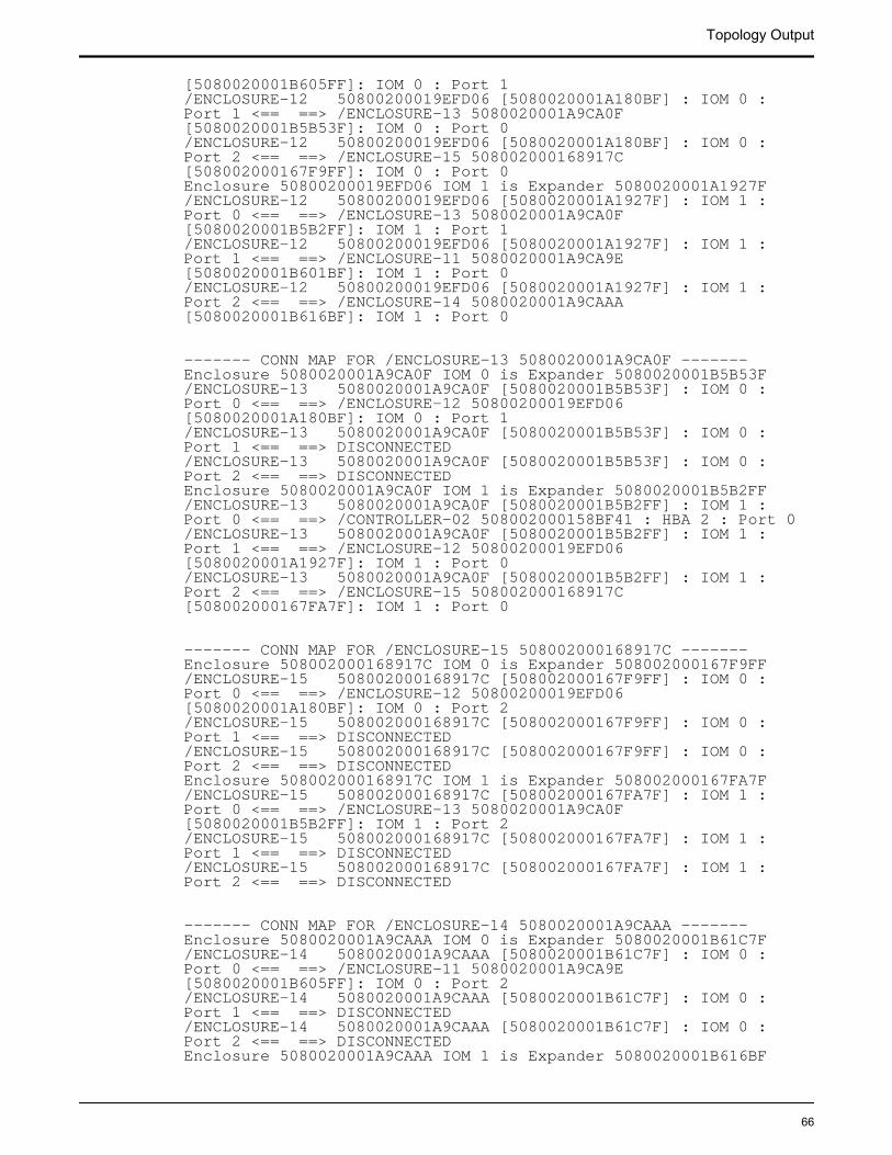
[5080020001B605FF]: IOM 0 : Port 1/ENCLOSURE-12 50800200019EFD06 [5080020001A180BF] : IOM 0 : Port 1 <== ==> /ENCLOSURE-13 5080020001A9CA0F [5080020001B5B53F]: IOM 0 : Port 0/ENCLOSURE-12 50800200019EFD06 [5080020001A180BF] : IOM 0 : Port 2 <== ==> /ENCLOSURE-15 508002000168917C [508002000167F9FF]: IOM 0 : Port 0Enclosure 50800200019EFD06 IOM 1 is Expander 5080020001A1927F/ENCLOSURE-12 50800200019EFD06 [5080020001A1927F] : IOM 1 : Port 0 <== ==> /ENCLOSURE-13 5080020001A9CA0F [5080020001B5B2FF]: IOM 1 : Port 1/ENCLOSURE-12 50800200019EFD06 [5080020001A1927F] : IOM 1 : Port 1 <== ==> /ENCLOSURE-11 5080020001A9CA9E [5080020001B601BF]: IOM 1 : Port 0/ENCLOSURE-12 50800200019EFD06 [5080020001A1927F] : IOM 1 : Port 2 <== ==> /ENCLOSURE-14 5080020001A9CAAA [5080020001B616BF]: IOM 1 : Port 0
------- CONN MAP FOR /ENCLOSURE-13 5080020001A9CA0F -------Enclosure 5080020001A9CA0F IOM 0 is Expander 5080020001B5B53F/ENCLOSURE-13 5080020001A9CA0F [5080020001B5B53F] : IOM 0 : Port 0 <== ==> /ENCLOSURE-12 50800200019EFD06 [5080020001A180BF]: IOM 0 : Port 1/ENCLOSURE-13 5080020001A9CA0F [5080020001B5B53F] : IOM 0 : Port 1 <== ==> DISCONNECTED/ENCLOSURE-13 5080020001A9CA0F [5080020001B5B53F] : IOM 0 : Port 2 <== ==> DISCONNECTEDEnclosure 5080020001A9CA0F IOM 1 is Expander 5080020001B5B2FF/ENCLOSURE-13 5080020001A9CA0F [5080020001B5B2FF] : IOM 1 : Port 0 <== ==> /CONTROLLER-02 508002000158BF41 : HBA 2 : Port 0/ENCLOSURE-13 5080020001A9CA0F [5080020001B5B2FF] : IOM 1 : Port 1 <== ==> /ENCLOSURE-12 50800200019EFD06 [5080020001A1927F]: IOM 1 : Port 0/ENCLOSURE-13 5080020001A9CA0F [5080020001B5B2FF] : IOM 1 : Port 2 <== ==> /ENCLOSURE-15 508002000168917C [508002000167FA7F]: IOM 1 : Port 0
------- CONN MAP FOR /ENCLOSURE-15 508002000168917C -------Enclosure 508002000168917C IOM 0 is Expander 508002000167F9FF/ENCLOSURE-15 508002000168917C [508002000167F9FF] : IOM 0 : Port 0 <== ==> /ENCLOSURE-12 50800200019EFD06 [5080020001A180BF]: IOM 0 : Port 2/ENCLOSURE-15 508002000168917C [508002000167F9FF] : IOM 0 : Port 1 <== ==> DISCONNECTED/ENCLOSURE-15 508002000168917C [508002000167F9FF] : IOM 0 : Port 2 <== ==> DISCONNECTEDEnclosure 508002000168917C IOM 1 is Expander 508002000167FA7F/ENCLOSURE-15 508002000168917C [508002000167FA7F] : IOM 1 : Port 0 <== ==> /ENCLOSURE-13 5080020001A9CA0F [5080020001B5B2FF]: IOM 1 : Port 2/ENCLOSURE-15 508002000168917C [508002000167FA7F] : IOM 1 : Port 1 <== ==> DISCONNECTED/ENCLOSURE-15 508002000168917C [508002000167FA7F] : IOM 1 : Port 2 <== ==> DISCONNECTED
------- CONN MAP FOR /ENCLOSURE-14 5080020001A9CAAA -------Enclosure 5080020001A9CAAA IOM 0 is Expander 5080020001B61C7F/ENCLOSURE-14 5080020001A9CAAA [5080020001B61C7F] : IOM 0 : Port 0 <== ==> /ENCLOSURE-11 5080020001A9CA9E [5080020001B605FF]: IOM 0 : Port 2/ENCLOSURE-14 5080020001A9CAAA [5080020001B61C7F] : IOM 0 : Port 1 <== ==> DISCONNECTED/ENCLOSURE-14 5080020001A9CAAA [5080020001B61C7F] : IOM 0 : Port 2 <== ==> DISCONNECTEDEnclosure 5080020001A9CAAA IOM 1 is Expander 5080020001B616BF
Topology Output
66
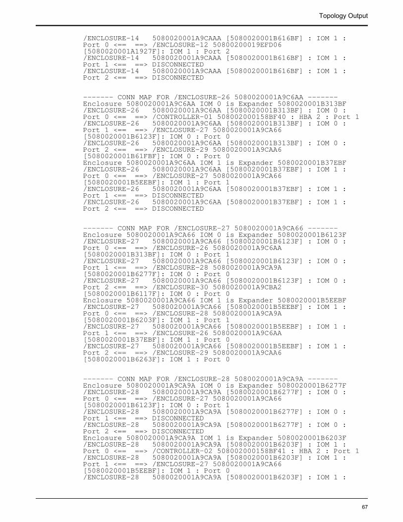
/ENCLOSURE-14 5080020001A9CAAA [5080020001B616BF] : IOM 1 : Port 0 <== ==> /ENCLOSURE-12 50800200019EFD06 [5080020001A1927F]: IOM 1 : Port 2/ENCLOSURE-14 5080020001A9CAAA [5080020001B616BF] : IOM 1 : Port 1 <== ==> DISCONNECTED/ENCLOSURE-14 5080020001A9CAAA [5080020001B616BF] : IOM 1 : Port 2 <== ==> DISCONNECTED
------- CONN MAP FOR /ENCLOSURE-26 5080020001A9C6AA -------Enclosure 5080020001A9C6AA IOM 0 is Expander 5080020001B313BF/ENCLOSURE-26 5080020001A9C6AA [5080020001B313BF] : IOM 0 : Port 0 <== ==> /CONTROLLER-01 508002000158BF40 : HBA 2 : Port 1/ENCLOSURE-26 5080020001A9C6AA [5080020001B313BF] : IOM 0 : Port 1 <== ==> /ENCLOSURE-27 5080020001A9CA66 [5080020001B6123F]: IOM 0 : Port 0/ENCLOSURE-26 5080020001A9C6AA [5080020001B313BF] : IOM 0 : Port 2 <== ==> /ENCLOSURE-29 5080020001A9CAA6 [5080020001B61FBF]: IOM 0 : Port 0Enclosure 5080020001A9C6AA IOM 1 is Expander 5080020001B37EBF/ENCLOSURE-26 5080020001A9C6AA [5080020001B37EBF] : IOM 1 : Port 0 <== ==> /ENCLOSURE-27 5080020001A9CA66 [5080020001B5EEBF]: IOM 1 : Port 1/ENCLOSURE-26 5080020001A9C6AA [5080020001B37EBF] : IOM 1 : Port 1 <== ==> DISCONNECTED/ENCLOSURE-26 5080020001A9C6AA [5080020001B37EBF] : IOM 1 : Port 2 <== ==> DISCONNECTED
------- CONN MAP FOR /ENCLOSURE-27 5080020001A9CA66 -------Enclosure 5080020001A9CA66 IOM 0 is Expander 5080020001B6123F/ENCLOSURE-27 5080020001A9CA66 [5080020001B6123F] : IOM 0 : Port 0 <== ==> /ENCLOSURE-26 5080020001A9C6AA [5080020001B313BF]: IOM 0 : Port 1/ENCLOSURE-27 5080020001A9CA66 [5080020001B6123F] : IOM 0 : Port 1 <== ==> /ENCLOSURE-28 5080020001A9CA9A [5080020001B6277F]: IOM 0 : Port 0/ENCLOSURE-27 5080020001A9CA66 [5080020001B6123F] : IOM 0 : Port 2 <== ==> /ENCLOSURE-30 5080020001A9CBA2 [5080020001B6117F]: IOM 0 : Port 0Enclosure 5080020001A9CA66 IOM 1 is Expander 5080020001B5EEBF/ENCLOSURE-27 5080020001A9CA66 [5080020001B5EEBF] : IOM 1 : Port 0 <== ==> /ENCLOSURE-28 5080020001A9CA9A [5080020001B6203F]: IOM 1 : Port 1/ENCLOSURE-27 5080020001A9CA66 [5080020001B5EEBF] : IOM 1 : Port 1 <== ==> /ENCLOSURE-26 5080020001A9C6AA [5080020001B37EBF]: IOM 1 : Port 0/ENCLOSURE-27 5080020001A9CA66 [5080020001B5EEBF] : IOM 1 : Port 2 <== ==> /ENCLOSURE-29 5080020001A9CAA6 [5080020001B6263F]: IOM 1 : Port 0
------- CONN MAP FOR /ENCLOSURE-28 5080020001A9CA9A -------Enclosure 5080020001A9CA9A IOM 0 is Expander 5080020001B6277F/ENCLOSURE-28 5080020001A9CA9A [5080020001B6277F] : IOM 0 : Port 0 <== ==> /ENCLOSURE-27 5080020001A9CA66 [5080020001B6123F]: IOM 0 : Port 1/ENCLOSURE-28 5080020001A9CA9A [5080020001B6277F] : IOM 0 : Port 1 <== ==> DISCONNECTED/ENCLOSURE-28 5080020001A9CA9A [5080020001B6277F] : IOM 0 : Port 2 <== ==> DISCONNECTEDEnclosure 5080020001A9CA9A IOM 1 is Expander 5080020001B6203F/ENCLOSURE-28 5080020001A9CA9A [5080020001B6203F] : IOM 1 : Port 0 <== ==> /CONTROLLER-02 508002000158BF41 : HBA 2 : Port 1/ENCLOSURE-28 5080020001A9CA9A [5080020001B6203F] : IOM 1 : Port 1 <== ==> /ENCLOSURE-27 5080020001A9CA66 [5080020001B5EEBF]: IOM 1 : Port 0/ENCLOSURE-28 5080020001A9CA9A [5080020001B6203F] : IOM 1 :
Topology Output
67
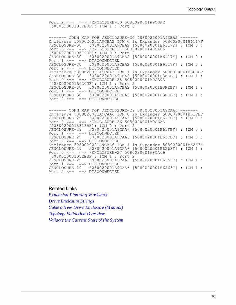
Port 2 <== ==> /ENCLOSURE-30 5080020001A9CBA2 [5080020001B3FEBF]: IOM 1 : Port 0
------- CONN MAP FOR /ENCLOSURE-30 5080020001A9CBA2 -------Enclosure 5080020001A9CBA2 IOM 0 is Expander 5080020001B6117F/ENCLOSURE-30 5080020001A9CBA2 [5080020001B6117F] : IOM 0 : Port 0 <== ==> /ENCLOSURE-27 5080020001A9CA66 [5080020001B6123F]: IOM 0 : Port 2/ENCLOSURE-30 5080020001A9CBA2 [5080020001B6117F] : IOM 0 : Port 1 <== ==> DISCONNECTED/ENCLOSURE-30 5080020001A9CBA2 [5080020001B6117F] : IOM 0 : Port 2 <== ==> DISCONNECTEDEnclosure 5080020001A9CBA2 IOM 1 is Expander 5080020001B3FEBF/ENCLOSURE-30 5080020001A9CBA2 [5080020001B3FEBF] : IOM 1 : Port 0 <== ==> /ENCLOSURE-28 5080020001A9CA9A [5080020001B6203F]: IOM 1 : Port 2/ENCLOSURE-30 5080020001A9CBA2 [5080020001B3FEBF] : IOM 1 : Port 1 <== ==> DISCONNECTED/ENCLOSURE-30 5080020001A9CBA2 [5080020001B3FEBF] : IOM 1 : Port 2 <== ==> DISCONNECTED
------- CONN MAP FOR /ENCLOSURE-29 5080020001A9CAA6 -------Enclosure 5080020001A9CAA6 IOM 0 is Expander 5080020001B61FBF/ENCLOSURE-29 5080020001A9CAA6 [5080020001B61FBF] : IOM 0 : Port 0 <== ==> /ENCLOSURE-26 5080020001A9C6AA [5080020001B313BF]: IOM 0 : Port 2/ENCLOSURE-29 5080020001A9CAA6 [5080020001B61FBF] : IOM 0 : Port 1 <== ==> DISCONNECTED/ENCLOSURE-29 5080020001A9CAA6 [5080020001B61FBF] : IOM 0 : Port 2 <== ==> DISCONNECTEDEnclosure 5080020001A9CAA6 IOM 1 is Expander 5080020001B6263F/ENCLOSURE-29 5080020001A9CAA6 [5080020001B6263F] : IOM 1 : Port 0 <== ==> /ENCLOSURE-27 5080020001A9CA66 [5080020001B5EEBF]: IOM 1 : Port 2/ENCLOSURE-29 5080020001A9CAA6 [5080020001B6263F] : IOM 1 : Port 1 <== ==> DISCONNECTED/ENCLOSURE-29 5080020001A9CAA6 [5080020001B6263F] : IOM 1 : Port 2 <== ==> DISCONNECTED
Related LinksExpansion Planning WorksheetDrive Enclosure StringsCable a New Drive Enclosure (Manual)Topology Validation OverviewValidate the Current State of the System
Topology Output
68
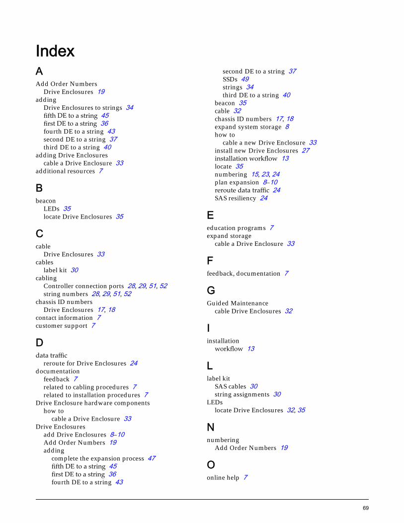
IndexAAdd Order Numbers
Drive Enclosures 19adding
Drive Enclosures to strings 34fifth DE to a string 45first DE to a string 36fourth DE to a string 43second DE to a string 37third DE to a string 40
adding Drive Enclosurescable a Drive Enclosure 33
additional resources 7
Bbeacon
LEDs 35locate Drive Enclosures 35
Ccable
Drive Enclosures 33cables
label kit 30cabling
Controller connection ports 28, 29, 51, 52string numbers 28, 29, 51, 52
chassis ID numbersDrive Enclosures 17, 18
contact information 7customer support 7
Ddata traffic
reroute for Drive Enclosures 24documentation
feedback 7related to cabling procedures 7related to installation procedures 7
Drive Enclosure hardware componentshow to
cable a Drive Enclosure 33Drive Enclosures
add Drive Enclosures 8–10Add Order Numbers 19adding
complete the expansion process 47fifth DE to a string 45first DE to a string 36fourth DE to a string 43
second DE to a string 37SSDs 49strings 34third DE to a string 40
beacon 35cable 32chassis ID numbers 17, 18expand system storage 8how to
cable a new Drive Enclosure 33install new Drive Enclosures 27installation workflow 13locate 35numbering 15, 23, 24plan expansion 8–10reroute data traffic 24SAS resiliency 24
Eeducation programs 7expand storage
cable a Drive Enclosure 33
Ffeedback, documentation 7
GGuided Maintenance
cable Drive Enclosures 32
Iinstallation
workflow 13
Llabel kit
SAS cables 30string assignments 30
LEDslocate Drive Enclosures 32, 35
Nnumbering
Add Order Numbers 19
Oonline help 7
69
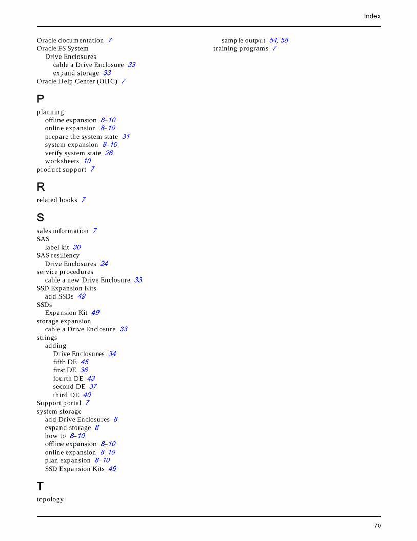
Oracle documentation 7Oracle FS System
Drive Enclosurescable a Drive Enclosure 33expand storage 33
Oracle Help Center (OHC) 7
Pplanning
offline expansion 8–10online expansion 8–10prepare the system state 31system expansion 8–10verify system state 26worksheets 10
product support 7
Rrelated books 7
Ssales information 7SAS
label kit 30SAS resiliency
Drive Enclosures 24service procedures
cable a new Drive Enclosure 33SSD Expansion Kits
add SSDs 49SSDs
Expansion Kit 49storage expansion
cable a Drive Enclosure 33strings
addingDrive Enclosures 34fifth DE 45first DE 36fourth DE 43second DE 37third DE 40
Support portal 7system storage
add Drive Enclosures 8expand storage 8how to 8–10offline expansion 8–10online expansion 8–10plan expansion 8–10SSD Expansion Kits 49
Ttopology
sample output 54, 58training programs 7
Index
70