Embed Size (px)
Citation preview

Oracle Communications Diameter Signaling Router
Release 7.0 Feature Guide
O R A C L E W H I T E P A P E R | M A R C H 2 0 1 5

1 | ORACLE COMMUNICATIONS DIAMETER SIGNALING ROUTER RELEASE 7.0 FEATURE GUIDE
Table of Contents
List of Terms 8
INTRODUCTION TO DIAMETER SIGNALING ROUTER 10
Diameter Routing Challenges 10
Diameter Signaling Router Solution 12
DSR FEATURES AND FUNCTIONS 14
Overview 14
Operations, Administration and Maintenance 15
Diameter Agent Message Processor (DA MP) 16
SS7 Message Processor (SS7 MP) 16
IP Front End (IPFE) 16
Session / Subscriber Binding Repository (SBR) 16
Subscriber Data Server (SDS) 17
Database Processor (DP) 17
Query Server (QS) 18
Integrated Diameter Intelligence Hub (IDIH) 18
DSR Nodes (Identity) 18
Diameter Core Routing 19
Transport 24
Message Priority Configuration Set (MPCS) 27
Peer Routing Table (PRT) 27
Application Routing Table (ART) 29
IPSec 30

2 | ORACLE COMMUNICATIONS DIAMETER SIGNALING ROUTER RELEASE 7.0 FEATURE GUIDE
Connectivity Enhancements 30
Configurable Disable of CEx Peer IP Validation 30
Alternate Routing Options 30
Congestion Control 31
Pending Answer Timer by Ingress Peer 42
DNS Support 43
Diameter Mediation 43
Rule Templates and Rules 44
States of a Rule Template 45
Trigger Points 45
Measurements Associated with Rules 45
AVP Dictionaries 45
IP Front End (IPFE) 46
Traffic Distribution 46
Connection balancing 47
High availability 47
Topology Hiding 47
Path Topology Hiding 47
S6a/S6d MME/SGSN Topology Hiding 51
S6a/S6d HSS Topology Hiding 53
S9 PCRF Topology Hiding 55
S9 AF/pCSCF Topology Hiding 55
DSR Applications 56

3 | ORACLE COMMUNICATIONS DIAMETER SIGNALING ROUTER RELEASE 7.0 FEATURE GUIDE
Offline Charging Proxy (OFCS) 56
Range Based Address Resolution (RBAR) 57
Full Address Based Resolution (FABR) 57
MAP-Diameter IWF 59
Policy and Charging Application (PCA) 59
Gateway Location Application (GLA) 69
Diameter Message Copy 71
Integrated Diameter Intelligence Hub (IDIH) 72
Supported Interfaces 73
Flexible IP Addressing 74
Subscriber Data Server (SDS) Integration 75
Bulk Import/Export 76
High-Availability 77
Capacity and Performance 77
DSR OAM&P 77
Overview 77
Network Interfaces 78
Web-Based GUI 78
Operations and Provisioning 78
Network Information 79
Network Elements 79
Maintenance 79
Alarms and Events 79

4 | ORACLE COMMUNICATIONS DIAMETER SIGNALING ROUTER RELEASE 7.0 FEATURE GUIDE
Key Performance Indicators 80
Measurements 81
Automatic Performance Data Export (APDE) 84
Administration 84
Database Management 84
File Management 84
Security 85

5 | ORACLE COMMUNICATIONS DIAMETER SIGNALING ROUTER RELEASE 7.0 FEATURE GUIDE
FIGURE 1 - SELECTED DIAMETER INTERFACES IN LTE AND IMS ........................................ 10
FIGURE 2 - 3GPP INTER/INTRA-OPERATOR DIAMETER INFRASTRUCTURE ...................... 12
FIGURE 3 - GSMA ROAMING IMPLEMENTATION ARCHITECTURE ....................................... 12
FIGURE 4 – EXAMPLE OF OPERATOR’S EPC/IMS CORE NETWORK WITH DSR ................. 13
FIGURE 5 - DSR 7.0 ARCHITECTURE ........................................................................................ 15
FIGURE 6 - MULTIPLE NODES PER MESSAGE PROCESSOR ................................................ 19
FIGURE 7 - HIGH LEVEL MESSAGE PROCESSING AND ROUTING IN DSR .......................... 20
FIGURE 8 - CONNECTION ROUTE GROUP ............................................................................... 22
FIGURE 9 - ROUTE LIST, ROUTE GROUP, PEER RELATIONSHIP EXAMPLE ....................... 23
FIGURE 10 - LOAD BALANCING BASED ON ROUTE GROUPS AND PEER WEIGHTS ......... 24
FIGURE 11 SCTP MULTI-HOMING ............................................................................................. 26
FIGURE 12 - SCTP MULTI-HOMING VIA PORT BONDING ........................................................ 27
FIGURE 13 - DSR INGRESS MPS CONFIGURATION EXAMPLE 1 - NORMAL CASE ............. 33
FIGURE 14 - MESSAGE COLORING AND PRIORITY/COLOR-BASED DA-MP OVERLOAD CONTROL ............................................................................................................................. 34
FIGURE 15 – EXAMPLE CONGESTION LEVEL ABATEMENT .................................................. 37
FIGURE 16 - DSR PER-CONNECTION EGRESS THROTTLING ................................................ 38
FIGURE 17 - DSR AGGREGATE AND PER-CONNECTION EGRESS THROTTLING ............... 39
FIGURE 18 - CONNECTION BUSY .............................................................................................. 41
FIGURE 19 - CONGESTION LEVEL ABATEMENT OVER TIME FOR REMOTE BUSY ............ 42
FIGURE 20 - PROXY-HOST TOPOLOGY HIDING MESSAGE FLOW ........................................ 50
FIGURE 21 - MME/SGSN TOPOLOGY HIDING ........................................................................... 51
FIGURE 22 - S6A/S6D HSS TOPOLOGY HIDING - ULR MESSAGE FLOW .............................. 54
FIGURE 23 - S6A/S6D HSS TOPOLOGY HIDING CLR MESSAGE FLOW ................................ 55
FIGURE 24 - CHARGING PROXY NETWORK ARCHITECTURE ............................................... 57
FIGURE 25 - DSR WITH MAP-DIAMETER IWF ........................................................................... 59
FIGURE 26 - ONLINE CHARGING SYSTEM AND ARCHITECTURE ......................................... 61
FIGURE 27: A TYPICAL ONLINE CHARGING SESSION ........................................................... 62
FIGURE 28 – NETWORK VIEW OF P-DRA MATED PAIRS........................................................ 63
FIGURE 29 - OVERALL PCC LOGICAL ARCHITECTURE (NON-ROAMING) ........................... 64

6 | ORACLE COMMUNICATIONS DIAMETER SIGNALING ROUTER RELEASE 7.0 FEATURE GUIDE
FIGURE 30 - PCRF TOPOLOGY HIDING..................................................................................... 66
FIGURE 31 - RELATIONSHIP BETWEEN APNS AND PCRF POOLS ....................................... 67
FIGURE 32 - RELATIONSHIP BETWEEN IMSIS AND PCRF POOLS ........................................ 68
FIGURE 33 - PCA EXAMPLE DEPLOYMENT ............................................................................. 69
FIGURE 34 - IMSI QUERY WITH SINGLE MATCHING GX SESSION USE CASE ..................... 70
FIGURE 35 - PCA AND GLA NOAM ARCHITECTURE ............................................................... 71
FIGURE 36 - MESSAGE COPY OVERVIEW ................................................................................ 72
FIGURE 37 - IDIH TRACE DATA .................................................................................................. 73
FIGURE 38 - SUBSCRIBER DATA SERVER ARCHITECTURE ................................................. 76
FIGURE 39 - DSR 3-TIERED TOPOLOGY ARCHITECTURE ...................................................... 78
FIGURE 40 FLOW OF ALARMS .................................................................................................. 80

7 | ORACLE COMMUNICATIONS DIAMETER SIGNALING ROUTER RELEASE 7.0 FEATURE GUIDE
List of Tables
TABLE 1: PRT PRECEDENCE ..................................................................................................... 29
TABLE 2 DSR INGRESS MPS CONFIGURATION EXAMPLE 1 ................................................. 32
TABLE 3 CONGESTION LEVELS BASED ON REMOTE BUSY................................................. 42
TABLE 4 MME/SGSN PSEUDO-HOST NAME MAPPING ........................................................... 52
TABLE 5 DSR KPI SUMMARY ..................................................................................................... 80
TABLE 6 PLATFORM KPI SUMMARY ........................................................................................ 81
TABLE 7 DSR MEASUREMENTS ................................................................................................ 82

8 | ORACLE COMMUNICATIONS DIAMETER SIGNALING ROUTER RELEASE 7.0 FEATURE GUIDE
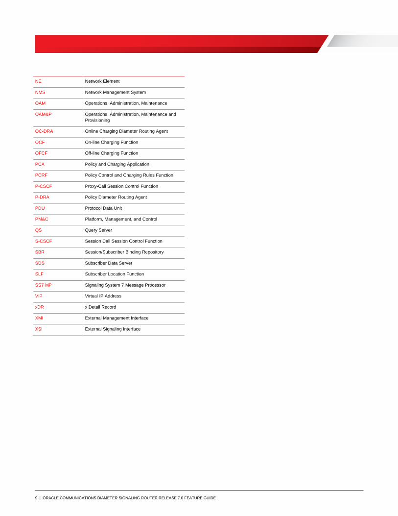
List of Terms
Acronym Meaning
ACL Access Control List
APDE Automatic Performance Data Export
AVP Attribute Value Pair
CLI Command Line Interface
DA Diameter Agent
DA-MP Diameter Agent Message Processor
DAS Diameter Application Server
DEA Diameter Edge Agent
DIH Diameter Intelligence Hub
DNS Domain Name Server
DP Database Processor
DR Disaster Recovery
EMS Element Management System
EPC Evolved Packet Core
FQDN Fully Qualified Domain Name
GLA Gateway Location Application
GUI Graphical User Interface
HSS Home Subscriber Server
I-CSCF Integrated Cal Session Control Function
IDIH Integrated Diameter Intelligence Hub
ILO Integrated Lights Out
IMI Internal Management Interface
IMS IP Multi-media System
IOT Interoperability Tests
IWF Interworking Function
KPI Key Performance Indicator
LTE Long Term Evolution
MEAL Measurements, Events, Alarms, and Logging
MME Mobility Management Entity
MP Message Processor
MPS Messages per Second
M-D IWF Map to Diameter Interworking
9 | ORACLE COMMUNICATIONS DIAMETER SIGNALING ROUTER RELEASE 7.0 FEATURE GUIDE
NE Network Element
NMS Network Management System
OAM Operations, Administration, Maintenance
OAM&P Operations, Administration, Maintenance and
Provisioning
OC-DRA Online Charging Diameter Routing Agent
OCF On-line Charging Function
OFCF Off-line Charging Function
PCA Policy and Charging Application
PCRF Policy Control and Charging Rules Function
P-CSCF Proxy-Call Session Control Function
P-DRA Policy Diameter Routing Agent
PDU Protocol Data Unit
PM&C Platform, Management, and Control
QS Query Server
S-CSCF Session Call Session Control Function
SBR Session/Subscriber Binding Repository
SDS Subscriber Data Server
SLF Subscriber Location Function
SS7 MP Signaling System 7 Message Processor
VIP Virtual IP Address
xDR x Detail Record
XMI External Management Interface
XSI External Signaling Interface

10 | ORACLE COMMUNICATIONS DIAMETER SIGNALING ROUTER RELEASE 7.0 FEATURE GUIDE
INTRODUCTION TO DIAMETER SIGNALING ROUTER
Mobile data traffic is skyrocketing, fueled by the introduction of smartphones, laptop dongles, flat-rate plans, social
networking and applications like mobile video. Operators are looking to all-Internet protocol (IP) networks such as
long term evolution (LTE) and IP multimedia subsystem (IMS) to provide the bandwidth required to support data-
hungry devices and applications and to cost effectively address the growing gap between traffic and revenue
growth.
The 3GPP Evolved Packet core (EPC) and IP Multimedia Subsytem (IMS) network architectures have specified the
use of Diameter over stream control transmission protocol (SCTP) or transmission control protocol (TCP) for many
network interfaces such as for policy, charging, authentication and mobility management. Many of these interfaces
are illustrated in the figure below. Diameter is also defined by 3GPP and ETSI standard bodies as the foundation for
Authentication, Authorization and Accounting (AAA) functions in the Next Generation Network (NGN).
Figure 1 - Selected Diameter Interfaces in LTE and IMS
Diameter Routing Challenges
For years operators have employed signaling system 7 (SS7) as the international, standardized protocol to
communicate globally between operator networks. In LTE and IMS networks, many of the functions performed by
SS7-based signaling in current networks are replaced by equivalent functions based on the Diameter protocol.
Operators will expect the same network behavior and robustness as they enjoy with SS7 networks today.
Foreign LTE Domain
Home LTE/IMS Domain
Foreign GPRS Domain
S13
S6a S9S6d
GxGz
Gy
Cx
Sh
Rx
Ro
Rf
Rc Re
EIR
vMME vPCRF
PGW
AF
ABMF RF
OFCF
MAP-Diam
IWF
vSGSN
vS4-SGSN
OCF
EPC Equipment
Check
AS Access
to HSS
IMS PCC
IMS
Charging
EPC
Charging
IMS
Registration
EPC Mobility
Management
MME
I/S-CSCFPCRF
P-CSCF
IP-SM-GWAAAHSS
SLF
Gr

11 | ORACLE COMMUNICATIONS DIAMETER SIGNALING ROUTER RELEASE 7.0 FEATURE GUIDE
Without a separate Diameter signaling infrastructure at the network core to facilitate signaling between network
elements, endpoints such as mobility management entities (MMEs) and home subscriber servers (HSSs) must
utilize direct signaling connections to each other, forming a mesh-like network architecture. Network endpoints must
handle all session-related tasks such as routing, traffic management, redundancy and service implementation.
Implementing an IMS or LTE network without a signaling framework may be sufficient initially, but as traffic levels
grow, the lack of a capable signaling infrastructure poses a number of challenges:
Scalability and load balancing: Each endpoint must maintain a separate SCTP association or TCP
connection with each of its Diameter peers as well as the status of each, placing a heavy burden on the
endpoints as the number of nodes grows. This burden is made more complex with the responsibility of
load balancing placed on each end point.
Congestion control: Diameter lacks the well-defined congestion control mechanisms found in other
protocols such as SS7. For example, if an HSS has multiple Diameter front ends, the lack of sufficient
congestion control increases the risk of a cascading HSS failure.
Secure Network interconnect: A fully meshed network is completely unworkable when dealing with
connections to other networks because there is no central interconnect point, which also exposes the
operator’s network topology to other operators and can lead to security breaches.
Interoperability: Protocol interworking becomes unmanageable as the number of devices supplied by
multiple vendors increases. With no separate signaling or session framework, interoperability testing (IOT)
must be performed at every existing node when a new node or software load is placed in service. IOT
activities consume a considerable amount of operator time and resources, with costs increasing in
proportion to the number of tests that must be performed.
Support for legacy EIR: A need for MAP to Diameter interworking is required as transitions are made and
LTE is quickly introduced into a network while still needing to support legacy HLRs.
Support for both SCTP and TCP implementations: SCTP elements cannot communicate with TCP
elements. Without a central conversion element, operators will either have to upgrade TCP elements or
require all elements in the network to support both stacks.
Subscriber to HSS mapping: When there are multiple HSSs in the network, subscribers may be homed
on different HSSs. Therefore, there must be some function in the network that maps subscriber identities
to HSSs. With no separate Diameter signaling infrastructure, that task must be handled by a standalone
subscription locator function (SLF), or by the HSS itself. Either approach wastes MME (or call session
control function [CSCF]) processing and can add unnecessary delays. The HSS approach wastes HSS
resources and may even result in the need for more HSSs than would otherwise be necessary.
Policy and charging rules function (PCRF) binding: When multiple PCRFs are required in the network,
there must be a way to ensure that all messages associated with a user’s particular IP connectivity access
network (IP-CAN) session are processed by the same PCRF. This requires an element in the network that
maintains session binding dynamically.
In recognition of Diameter routing issues, 3GPP has defined the need for a Diameter signaling infrastructure and a
Diameter border infrastructure as shown below which is taken from TR 29.909. In addition, the GSMA has specified
the need for a Diameter Proxy Agent as shown below which is taken from PRD IR.88.

12 | ORACLE COMMUNICATIONS DIAMETER SIGNALING ROUTER RELEASE 7.0 FEATURE GUIDE
Figure 2 - 3GPP Inter/Intra-operator Diameter infrastructure
Figure 3 - GSMA roaming implementation architecture
Diameter Signaling Router Solution
Oracle Communication’s Diameter Signaling Router (DSR) creates a centralized core Diameter signaling layer that
relieves LTE, IMS and 3G Diameter endpoints of routing, traffic management and load balancing tasks and provides
a single interconnect point to other networks. Each endpoint only needs one connection to a DSR to gain access to
all other Diameter destinations reachable by the DSR. This approach eliminates the Diameter/SCTP (or TCP) mesh
that is created by having direct signaling connections between each network element. Having one or more
connection hubs that centralize the Diameter traffic to all end nodes simplifies interoperability between different
network elements and enhances network scalability.
Centralizing Diameter routing with a DSR creates a signaling architecture that reduces the cost and complexity of
the core network and enables core networks to grow incrementally to support increasing service and traffic
demands. It also facilitates network monitoring by providing a centralized vantage point in the signaling network.
A centralized signaling architecture:
Improves signaling performance and scalability by alleviating issues related to the limited signaling
capacity of MMEs, HSSs, CSCFs and other Diameter endpoints;
Provides a centralized point from which to implement load balancing;
Simplifies network expansion because routing configuration changes for new endpoints are performed only
on the DSR;
MMEMMEMME ...
Inner
Diameter
Relay Pool
Border
Diameter
Relay Pool
HSS
Inter-Operator Diameter
Infrastructure
S6a
S9
GRX/IPX MME
S4 SGSN
HSS
vPCRF hPCRF
S6
VPMN HPMN
DEA
DEA

13 | ORACLE COMMUNICATIONS DIAMETER SIGNALING ROUTER RELEASE 7.0 FEATURE GUIDE
Increases reliability by providing geographic redundancy;
Provides mediation point for Diameter variants to support interoperability between multi-vendor endpoints;
Creates a gateway to other networks to support roaming, security and topology hiding;
Reduces provisioning, maintenance and IOT costs associated with adding new network nodes;
Enables HSS routing flexibility by providing a central point to perform HSS address resolution;
Creates a centralized monitoring and network intelligence data collection point to isolate problems and
track key performance indicators (KPIs); and
Provides network-wide PCRF binding to ensure that all messages associated with a user’s particular IP-
CAN session are processed by the same PCRF.
The DSR can be deployed as a core router routing traffic between Diameter elements in the home network and as a
gateway router routing traffic between Diameter elements in the visited network and the home network. Refer to the
figure below for a representation of an operator’s EPC/IMS core network with DSR.
Figure 4 – Example of Operator’s EPC/IMS Core network with DSR
The resulting architecture enables IP networks to grow incrementally and systematically to support increasing
service and traffic demands. A centralized Diameter router is the ideal place to add other advanced network
functionalities like network performance intelligence via centralized monitoring, address resolution, Diameter
interworking and traffic steering.
Foreign LTE Domain
Home LTE/IMS Domain
Foreign GPRS Domain
ABMF RF
vSGSN
vS4-SGSN
vPCRF
Diameter
Agent
vMME
Diameter
Agent
IP-SM-GW
PGW
OCF
AF
OFCF
I/S-CSCF
PCRF
P-CSCFMME
EIR AAAHSS DSR
SLF
DiameterMap

14 | ORACLE COMMUNICATIONS DIAMETER SIGNALING ROUTER RELEASE 7.0 FEATURE GUIDE
DSR FEATURES AND FUNCTIONS
Overview
One primary function of the DSR is as a Diameter relay per RFC 6733 to route Diameter traffic based on provisioned
routing data. As a result, the DSR reduces the complexity and cost of maintaining a large number of SCTP
connections in LTE, IMS and 3G networks, simplifies the Diameter network and streamlines the provisioning of
Diameter interfaces. The DSR supports flexible traffic load sharing and redundancy schemes and offloads Diameter
clients and servers from having to perform many of these tasks, thereby reducing cost and time to market and
freeing up valuable resources in the end points.
DSR network elements are deployed in geographically diverse mated pairs with each NE servicing signaling traffic
to/from a collection of Diameter clients, servers and agents. The DSR Message Processor (MP) provides the
Diameter message handling function and each DSR MP supports connections to all Diameter peers (defined as an
element to which the DSR has a direct transport connection).
The figure below shows an overview of a DSR system architecture. Only single elements are shown for simplicity.
The key components of the solution are:
Operations, Administration, Maintenance and Provisioning (OAMP)
o System OAM per signaling node
o Network OAMP
Diameter Agent Message Processor (DA MP)
SS7 Message Processor
IP Front End (IPFE)
Session Binding Repository (SBR)
Database Processor (DP) / Subscriber Data Server (SDS)
Query Server (QS)
Integrated Diameter Intelligence Hub (IDIH)
These components are described at a high level in the following subsections. Although each component plays a key
role, the OAM and DA MP components are the mandatory components of the system.

15 | ORACLE COMMUNICATIONS DIAMETER SIGNALING ROUTER RELEASE 7.0 FEATURE GUIDE
Figure 5 - DSR 7.0 Architecture
Operations, Administration and Maintenance
The Operations, Administration, Maintenance and Provisioning components of the DSR include the System OAM
located at each signaling node and the Network OAMP (NOAMP).
Key characteristics of the Network OAMP are as follows:
centralized OAMP for the DSR network
supports SNMP northbound interface to operations support systems for fault management
runs on a pair of servers in active/standby configuration or can be virtualized on the System OAM blades at
one signaling site (for small systems with two DSR signaling nodes only)
optionally supports Disaster Recovery site for geographic redundancy
provides configuration and management of topology data
maintains event and security logs
centralizes collection and access to measurements and reports
Key characteristics of the System OAM at each signaling node are as follows:
centralized OAM interface for the node
provides mechanism to configure the diameter data (routing tables, mediation, etc.)
maintains local copy of the configuration database
supports SNMP northbound interface to operations support systems for fault management
provides mechanism to create user groups with various access levels
maintains event and security logs
16 | ORACLE COMMUNICATIONS DIAMETER SIGNALING ROUTER RELEASE 7.0 FEATURE GUIDE
centralizes collection and access to measurements and reports
Diameter Agent Message Processor (DA MP)
The DA MP hosts Proxy applications such as Address Resolution, Policy and Charging Application, Charging Proxy
etc. and scales by adding blades.
Key characteristics of a DA MP are as follows:
provides application specific handling of real-time Diameter messages
accesses DPs for real-time version of the subscriber DB, as needed
accesses session and subscriber binding from SBRs, as needed
interfaces with System OAM
SS7 Message Processor (SS7 MP)
The SS7 MP provides the MAP to Diameter interworking function.
Key characteristics of an SS7 MP are as follows:
performs message content conversion between MAP and Diameter.
performs address mapping between SS7 (SCCP/MTP) and Diameter.
supports 3G<->LTE authentication interworking as needed.
interfaces with System OAM
IP Front End (IPFE)
The DSR IP Front End provides TCP/SCTP connection based load balancing to hide the internal DSR hardware
architecture and IP addresses from the customer network. The IPFE is typically deployed in sets of Active-Active
pairs and it distributes connections to DA MPs. IPFE provides load balancing of connections to DA MPs. The
connections are active/active with TSAs (Target Set Addresses) and they provide TCP and SCTP connectivity.
Key characteristics of an IPFE are as follows:
optional component of the DSR
supports up to two active / standby pairs with 3.2 Gbps bandwidth per active/standby pair
Supported with SCTP Multi-homing
Session / Subscriber Binding Repository (SBR)
The SBR stores diameter sessions and subscriber bindings for stateful applications. Two stateful applications are
supported:
1. Charging Proxy Application (CPA) for off-line charging
2. Policy Charging Application (PCA) for Policy Diameter Routing Agent (Policy DRA) and Online Charging
Diameter Routing Agent (OC-DRA).

17 | ORACLE COMMUNICATIONS DIAMETER SIGNALING ROUTER RELEASE 7.0 FEATURE GUIDE
The off-line charging application uses charging SBRs (cSBR), OC-DRA uses session database SBRs (SBR(s)) and
Policy DRA uses both session database SBRs (SBR(s)) and subscriber binding database SBR’s (SBR(b)).
Throughout this document the SBRs are referred to individually when there are significant differences discussed,
and referred as SBR, without distinguishing the application, when the attribute applies to all types. The SBR scales
by adding blades.
Key characteristics of an SBR are as follows:
» optional component of the DSR
» provides repository for subscriber and session state data
» provides DSRs with network-wide access to bindings
Subscriber Data Server (SDS)
The SDS provides a centralized provisioning system for distributed subscriber data repository. The SDS is a highly-
scalable database with flexible schema.
Key characteristics of the SDS are as follows:
interfaces with provisioning systems to provision subscriber related data
interfaces with DPs at each DSR network element
replicates data to multiple sites
stores and maintains the master copy of the subscriber database
supports bulk download of data
correlates records belonging to a single subscriber
provides web based GUI for provisioning, configuration and administration of the data
supports SNMP v2c northbound interface to operations support systems for fault management
provides mechanism to create user groups with various access levels
provides automatic and manual audit to maintain integrity of the database
supports backup and restore of database
runs on a pair of servers in active / hot standby, and can provide geographic redundancy by deploying two
SDS pairs at diverse locations
Disaster Recovery site capabilities
Database Processor (DP)
The DP is the repository of subscriber data on the individual DSR node elements. The DP hosts the full address
resolution database and scales by adding blades.
Key characteristics of a DP are as follows:
provides high capacity real-time database query capability to DA MPs
interfaces with SDS for provisioning of subscriber data

18 | ORACLE COMMUNICATIONS DIAMETER SIGNALING ROUTER RELEASE 7.0 FEATURE GUIDE
maintains synchronization of data across all DPs
can also host other Oracle SDS based applications
Query Server (QS)
The Query Server contains a replicated copy of the local SDS database and supports a northbound MySQL
interface for free-form verification queries of the SDS Provisioning Database. The Query Server’s northbound
MySQL interface is accessible via its local server IP.
Key characteristics of the QS are as follows:
optional component that contains an instance of the subscriber DB
provides LDAP, XML and SQL access
Integrated Diameter Intelligence Hub (IDIH)
The IDIH supports advanced troubleshooting for Diameter traffic handled by the DSR. The IDIH is an optional
feature of the DSR that enable the selective collection and storage of diameter traffic and provides nodal diameter
troubleshooting.
DSR Nodes (Identity)
Each DSR message processor (MP) can host up to 48 Diameter Nodes (also called Diameter Identities). Hosting
more than one node/identity allows a DSR deployment at the Network Edge where DSR acts as the single point of
contact for all Diameter elements external to the operator network and similarly all internal Diameter elements use it
as the point of contact when reaching Diameter servers external to the operator network. Another use case for
hosting multiple Diameter nodes on each MP is to support multiple connections from an external Diameter element
to the DSR.
Each Diameter Node has the following attributes.
Diameter Realm that may be unique or shared across the nodes
Up to 128 local IP addresses - IPv4 or IPv6 addresses or a combination of IPv4 and IPv6 addresses.
(Each DA-MP supports up to 8 local IP addresses and 16 DA-MPs are supported)
A unique Fully Qualified Domain Name (FQDN)
DSR allows an IP address to be shared across nodes provided the combination of IP address, port and transport are
unique across nodes.
See Figure 6 for a sample configuration.

19 | ORACLE COMMUNICATIONS DIAMETER SIGNALING ROUTER RELEASE 7.0 FEATURE GUIDE
Figure 6 - Multiple Nodes per Message Processor
Diameter Core Routing
The DSR application provides a Diameter Routing Agent to forward messages to the appropriate destination based
on information contained within the message including header information and applicable Attribute Value Pairs
(AVP). As per the core Diameter specification, the DSR provides the capability to route Diameter messages based
on any combination, or presence/absence, of Destination-Host, Destination-Realm and Application-ID. In addition
DSR optionally provides the capability to look at Command-Code and origination information, namely Origin-Realm
and Origin-Host for advanced routing functionality. The average diameter message size supported is 2K bytes with a
maximum message size of 60K bytes.
DSR high level message processing and routing is shown below. The numbers show the message flow through the
system.
DSR MP
Home Network Foreign Network
AB
Node 1 Node 2
Example Node 1 (Identity 1)
Realm: home.operator.com
IPv4: 192.168.1.1
IPv6: fc00.0db8:85a3:08d3:1319:8a2e:0370:7334
FQDN: dsr18.home.operator.com
Example Node 2 (Identity 2)
Realm: foreign.operator.com
IPv4: 192.76.86.245
IPv6: 3ffe:1900:4545:3:200:f8ff:fe21:67cf
FQDN: dsr55.foreign.operator.com

20 | ORACLE COMMUNICATIONS DIAMETER SIGNALING ROUTER RELEASE 7.0 FEATURE GUIDE
Figure 7 - High Level Message Processing and Routing in DSR
DSR supports the following routing functions:
Message routing to Diameter peers based upon user-defined message content rules
Message routing to Diameter peers based upon user-defined priorities and weights
Message routing to Diameter peers with multiple transport connections
Alternate routing on connection failures
Alternate routing on Answer timeouts
Alternate routing on user-defined Answer responses
Route management based on peer transport connection status changes
Route management based on OAM configuration changes
Routing rules and rule actions are used to implement the routing behavior required by the operator. Routing rules
are defined using combinations of the following data elements:
Destination-Realm (leading, trailing characters, exact match, contains, not equal or don’t care)
Destination-Host (leading, trailing characters, exact match, contains, don’t care, present and not equal, or
presence/absence)
Application-ID (exact match, not equal, or don’t care)
Command-Code (exact match, not equal or don’t care)
Origin-Realm (leading, trailing characters, exact match, contains, not equal or don’t care)
• Policy and Charging
Application

21 | ORACLE COMMUNICATIONS DIAMETER SIGNALING ROUTER RELEASE 7.0 FEATURE GUIDE
Origin-Host (leading, trailing characters, exact match, contains, not equal or don’t care)
A set of configurable timers (100 – 10,000 milliseconds) control the length of time the DSR will wait to receive an
Answer to an outstanding Request. The maximum number of times a Request can be rerouted upon connection
failure or timeout is configurable from 0 – 4 retries.
DSR supports the concepts of routes, peer route tables, peer route groups, connection route groups, route lists, and
peer node groups to provide a very powerful and flexible load balancing solution. A Route List is comprised of a
prioritized list of peers or connections used for routing messages. Each route list supports the following configurable
information:
Route List ID
Up to 3 Route Groups containing a total of up to 480 Peer IDs or Connection IDs
Up to 160 Peers IDs or up to 64 Connection IDs per Route Group
Route Group Priority level (1 – 3)
Each Peer or Connection’s weight (1 – 64k)
When Peers/Connections have the same priority level a weight is assigned to each peer/connection which defines
the weighted distribution of messages amongst the peers/connections. For example, if two peers with equal priority
have weights 100 and 150 respectively then 40% of the messages will be forward to peer-1 (100/(100+150)) and
60% of the messages will be forward to peer-2 (150/(100+150)).
Peer Rout Tables can be assigned to Peer Nodes or Application IDs. Each Peer Route Table has its own set of
Peer Route Rules.
A set of peers with equal priority within a Route List is called a “Peer Route Group”. Multiple connections to the
same Peer can be assigned to a Connection Route Group (CRG). The use of CRGs allows for prioritized routing
between connections to the same peer. An example use case would be connecting to Peers across different sites
which share the same Hostname. The Peer within the site would be contacted for any traffic originated within the
site and the remote Peer should be contacted only if the local Peer is unavailable

22 | ORACLE COMMUNICATIONS DIAMETER SIGNALING ROUTER RELEASE 7.0 FEATURE GUIDE
Figure 8 - Connection Route Group
When multiple Route Groups are assigned to a Route List, only one of the Route Groups will be designated as the
"Active Route Group" for routing messages for that Route List. The remaining Route Groups within the Route List
are referred to as "Standby Route Groups". DSR will designate the "Active Route Group" within each Route List
based on the Route Group's priority and available capacity relative to the provisioned minimum capacity (described
below) of the Route List. When the "Operational Status" of peers change or the configuration of either the Route List
or Route Groups within the Route List change, then DSR may need to change the designated "Active Route Group"
for the Route List. An example of Route List and Route Group relationships is shown below.

23 | ORACLE COMMUNICATIONS DIAMETER SIGNALING ROUTER RELEASE 7.0 FEATURE GUIDE
Figure 9 - Route List, Route Group, Peer Relationship Example
Showing a different set of route lists and route groups, an example of peer routing based on Route Groups with a
Route List is shown in the figure below. DSR supports provisioning up to 160 routes in a route group (same priority)
and allows for provisioning of 3 route groups per route list.
Route List Table
Route Group – 1,Pri=1
Peer1, Wt=50
Peer2, Wt=50
Route Group – 2,Pri=2
Peer3, Wt=60
Peer4, Wt=40
Route Group – 3,Pri=1
Peer5, Wt=100
Route Group – 4,Pri=2
Peer6, Wt=25
Peer7, Wt=25
Peer8, Wt=30
Peer9, Wt=20
Route Group – 3,Pri=1
Peer5, Wt=100
Route List - 1
Route List - 2
Route List - 3

24 | ORACLE COMMUNICATIONS DIAMETER SIGNALING ROUTER RELEASE 7.0 FEATURE GUIDE
Figure 10 - Load Balancing Based on Route Groups and Peer Weights
To further enhance the load balancing scheme, the DSR allows the operator to provision a “minimum route list
capacity” threshold for each route list. This provisioned “minimum route list capacity” is compared against the route
group capacity. The route group capacity is dynamically computed based on the availability status of each route
within the route group and is the sum of all the weights of “available” routes in a route group. If the route group
capacity is higher than the threshold, the route group is considered “available” for routing messages. If the route
group capacity is lower (due to one of more failures on certain routes in the route group), the route group is not
considered “available” for routing messages. DSR uses the highest priority (lowest value) “available” route group
within a route list when routing messages over the route list. If none of the route groups in the route list are
“available”, DSR will use the route group with the most “available” capacity, also honoring route group priority, when
routing messages over the route list.
A peer node group is a configuration managed object that provides a container for a collection of DSR peer nodes
with like attributes (Example: same network element or same capacity requirement). The user configures DSR peer
nodes with their IP addresses in the peer node group container. Applications can use this IP address grouping for
various functions such as IPFE for a distribution algorithm.
Transport
The DSR supports SCTP and TCP transport simultaneously including support for both protocols to the same
Diameter peer. The DSR supports up to 64 connections per single Diameter peer which can either be uni-homed
via TCP or SCTP or multi-homed via SCTP. The DSR maintains the availability status of each Diameter peer.
Supported values are available, unavailable and degraded.
The following information are some of the configurable items for each connection:
• Peer Host FQDN, Realm ID and optionally IPv4 or IPv6 address
• Local Host and Realm ID (defined as part of the Diameter node)
• Message Priority Configuration Set
Peer1
Peer2
Peer3
Peer4
Peer5
Peer6
Peer7
W=40
W=30
W=30
W=60
W=40
W=50
W=50
Route Group-1 (Routes with Pri=1)
Route Group-2(Routes with Pri=2)
Route Group-3(Routes with Pri=3)
DSR
Route List-1
Route Group-1, Pri=1
Route Group-2, Pri=2
Route-1, Pri=1, Wt=40, Peer=1
Route-2, Pri=1, Wt=30, Peer=2
Route-1, Pri=2, Wt=60, Peer=4
Route-2, Pri=2, Wt=40, Peer=5
Route Group-3, Pri=3
Route-1, Pri=3, Wt=50, Peer=6
Route-2, Pri=3, Wt=50, Peer=7
Route-3, Pri=1, Wt=30, Peer=3

25 | ORACLE COMMUNICATIONS DIAMETER SIGNALING ROUTER RELEASE 7.0 FEATURE GUIDE
• Egress Throttling Configuration Set
• Remote Busy Usage / Remote Busy Abatement Timer
• Transport Congestion Abatement Time-out
• DSR Local Node status as the connection initiator only, initiator & responder (default) or responder-only
• Other connection characteristics such as timer values detailed below
• For SCTP connections:
RTO.Initial
RTO.Min
RTO.Max
RTO.Max.Init
Association.Max.Retrans
Path.Max.Retrans
Max.Init.Retrans
HB.Interval
SACK Delay
Maximum number of Inbound and Outbound Streams
Partial Reliability Lifetime
Socket Send/Rx Buffer
Max Burst
Datagram Bundling
Maximum Segment Size
Fragmentation Flag
Data Chunk Delivery Flag
• For TCP connections:
Nagle Algorithm ON/OFF indicator
Socket Send/Rx Buffer
Maximum Segment Size (bytes)
TCP Keep Alive
TCP Idle Time For Keep Alive
TCP Probe Interval For Keep Alive
TCP Keep Alive Max Count
• Diameter Connect Timer (Tc as per RFC6733)

26 | ORACLE COMMUNICATIONS DIAMETER SIGNALING ROUTER RELEASE 7.0 FEATURE GUIDE
• Diameter Watchdog Timer Initial value (Twinit as per RFC3539)
• Diameter Capabilities Exchange Timer (Oracle extension to RFC6733)
• Diameter Disconnect Timer (Oracle extension to RFC6733)
• Diameter Proving Mode (Oracle extension to RFC3539)
• Diameter Proving Timer (Oracle extension to RFC3539)
• Diameter Proving Times (Oracle extension to RFC3539)
DSR supports multiple SCTP streams as follows:
o DSR negotiates the number of SCTP inbound and outbound streams with peers per RFC4960 during
connection establishment using the number of streams configured for the connection
o DSR sends CER, CEA, DPR, and DPA messages on outbound stream 0
o If stream negotiation results in more than 1 outbound stream toward a peer, DSR evenly distributes DWR,
DWA, Request, and Answer messages across non-zero outbound streams
o DSR accepts and processes messages from the peer on any valid inbound stream
The DSR supports SCTP multi-homing as an option which provides a level of fault tolerance against IP network
failures. By implementing multi-homing the DSR can establish an alternate path to the Diameter peers it connects to
through the IP network using SCTP protocol. Failure of the primary network path will result in the DSR re-routing
Diameter messages through the configured alternate IP path. Multi-homed associations can be created through
multiple IP interfaces on a single MP blade. This is independent of any port bonding existing on the Ethernet
interfaces. Multi-homing is supported for both IPv4 & IPv6 networks but IPv4 and IPv6 cannot co-exist on the same
connection.
Figure 11 SCTP Multi-Homing

27 | ORACLE COMMUNICATIONS DIAMETER SIGNALING ROUTER RELEASE 7.0 FEATURE GUIDE
Figure 12 - SCTP Multi-Homing via Port Bonding
Message Priority Configuration Set (MPCS)
The MPCS defines how the message priority gets set. The following are some of the defined methods:
o Based on the connection upon which a message arrives
o Based on the peer from which a message is sent
o Based on an Application Routing Rule
o Based on a Peer Routing Rule
Each MPCS will contain the following information:
MPCS ID – The ID is used when associating the configuration set with a connection
o Set of Application-ID, Command-code, priority tuples, also called message priority rules
Application-ID – The Diameter application-ID. The application-id can be a wildcard
indicating that all application-ids match this message priority rule.
Command-code – The Diameter command-code. The command-code can be a
wildcard indicating that all command-codes within the specified application match this
message priority rule.
Note: If multiple command-codes with the same appl-id are to get the same message
priority then there will be a separate message priority rule tuple for each command-
code.
Priority – The priority applied to all request messages that match the Application-ID,
Command-Code combination.
This feature provides a method for DSR administrators to assign message priorities to incoming Diameter requests.
This priority configuration can be associated with a connection, peer node, application routing rule, or a peer routing
rule. As messages arrive they are marked with a message priority. Once the message priority is set it can be used
as input into decisions around load shedding and message throttling.
Peer Routing Table (PRT)

28 | ORACLE COMMUNICATIONS DIAMETER SIGNALING ROUTER RELEASE 7.0 FEATURE GUIDE
A peer route table is a set of prioritized peer routing rules that define routing to peer nodes based on message
content. Peer routing rules are prioritized lists of user-configured rules that define where to route a message to
upstream peer nodes. Routing is based on message content matching a peer routing rule’s conditions. There are
six peer routing rule parameters:
o Destination-Realm
o Destination-Host
o Application-ID
o Command-Code
o Origin-Realm
o Origin-Host
When a diameter message matches the condition of peer routing rules then the action specified for the rule will
occur. If you choose to route the diameter message to a peer node, the message is sent to a peer node in the
selected route list based on the route group priority and peer node configured capacity settings. If you choose to
send an answer, then the message is not routed and the specified diameter answer code is returned to the sender.
Peer routing rules are assigned a priority in relation to other peer routing rules. A message is handled based on the
highest priority routing rule that it matches. The lower the number a peer routing rule is assigned the higher priority it
will have. (1 is the highest priority and 1000 is the lowest priority.)
If a message does not match any of the peer routing rules and the destination-host parameter contains a Fully
Qualified Domain Name (FQDN) matching a peer node, then the message is directly routed to that peer node if it
has an available connection. If there is not an available connection, the message is routed using the alternate
implicit route configured for the peer node.
PRT Partitioning
Routing rules can be prioritized (1 – 1000) for cases where an inbound Diameter Request may match multiple user-
defined routing rules. The DSR supports up to 100 PRTs on the DSR. Any one of the PRTs can be optionally
associated with either the (Ingress) Peer or a Diameter Application-ID. A local application can also specify the PRT
that needs to be used for routing a Request. Each of these PRTs have no more than 1000 rules and the total
number of rules across all PRTs cannot exceed 10,000. A system wide PRT is also present by default and is used if
a PRT has not been assigned.
The PRT can be associated with the ingress peer node which can be useful to separate routing tables for example
for LTE domain, IMS domain, or routing partners.
Rule Action defines the action to perform when a routing rule is invoked. Actions supported are:
o Route to Peer - use Route List Table
o Send Answer Response - an Answer response is sent with a configurable Result-Code and no further
message processing occurs
o Abandon With No Answer - discard the message and no Answer is sent to the originating Peer Node.
The table below is used to determine the PRT instance to be used:

29 | ORACLE COMMUNICATIONS DIAMETER SIGNALING ROUTER RELEASE 7.0 FEATURE GUIDE
TABLE 1: PRT PRECEDENCE
PRT Used PRT specified by local
app (if supported)
PRT associated with
an Ingress Peer
PRT associated with
Diameter Application-
Id
Default PRT
Default PRT No No No Yes
Diameter
Application-Id
PRT
No No Yes Yes
Peer PRT No Yes Don’t Care Yes
Local App PRT Yes Don’t Care Don’t Care Yes Yes
Application Routing Table (ART)
An application route table contains one or more application routing rules that can be used for routing request
messages to DSR applications. Up to 400 application routing rules can be configured per application route table. Up
to 100 application route tables can be configured per DSR network element; a total of 1000 application routing rules
can be configured across the application route tables per network element.
An application routing rule defines message routing to a DSR application based on message content matching
the application routing rule's conditions. There are six application routing rule parameters:
Destination-Realm
Destination-Host
Application-Id
Command-Code
Origin-Realm
Origin-Host
When a diameter message matches the conditions of an application routing rule the message is routed to the
DSR application specified in the rule.
Rule Action defines the action to perform when a routing rule is invoked. Actions supported are:
o Route to Application - route the message to the local Application associated with this Rule
o Forward to Egress Routing - ART search stops and moves on to PRT
o Send Answer Response – ART generates an Answer. This Answer unwinds any previously encountered
DSR Applications that want to process the Answer. Normal controls for Answer are given (Result-Code vs
Experimental Result Code, Result-Code value, Vendor-ID, and ErrorMessage string)
o Abandon With No Answer - discard the message and no Answer is sent to the originating Peer Node
Application routing rules are assigned a priority in relation to other application routing rules. A message is handled
based on the highest priority routing rule that it matches. The lower the number an application routing rule is
assigned the higher priority it has. (1 is highest priority and 1000 is lowest priority.)
One or more DSR applications must be activated before application routing rules can be configured.

30 | ORACLE COMMUNICATIONS DIAMETER SIGNALING ROUTER RELEASE 7.0 FEATURE GUIDE
IPSec
The DSR optionally supports IPSec encryption per Diameter connection or association. Use of IPSec reduces MPS
throughput by up to 40%. IPSec is supported for SCTP over IPv6 connections. The DSR IPSec implementation is
based on 3GPP TS 33.210 version 9.0.0 and supports the following:
Encapsulating Security Payload (ESP)
Internet Key Exchange (IKE) v1 and v2
Tunnel Mode (entire IP packet is encrypted and/or authenticated)
Up to 100 tunnels
Encryption transforms/ciphers supported: ESP_3DES (default) and AES-CBC (128 bit key length)
Authentication transform supported: ESP_HMAC_SHA-1
Configurable Security Policy Database with backup and restore capability
Connectivity Enhancements
The Capability Exchanges on the DSR have been enhanced to provide flexibility to inter-op with other Diameter
nodes. These enhancements include:
Support of any Application –Id
Configurable list of Application-Ids (up to 10 maximum) that can be advertised to the peer on a per
connection basis
Authentication of minimum mandatory Application-Ids in the advertised list
Support for more than one Vendor specific Application-Id
Configurable Disable of CEx Peer IP Validation
The DSR provides a mechanism to enable or disable the validation of Host-IP-Address AVPs in the CEx message
against the actual peer connection IP address on a per connection configuration set basis.
Alternate Routing Options
This feature allows for the creation of up to 20 routing option sets (including default) which can then be optionally
associated with each peer or Diameter Application-id. When associated with a peer (Diameter->Configuration->Peer
Nodes), the ingress centric behaviors specified in associated routing option set will be used to determine the actions
to be performed by the DSR. When a routing option set is associated with a Diameter Application-id (Diameter-
>Configuration->Application Ids), these behaviors are applicable towards all peers for Requests that match the
application-id if and only if the peer has not been assigned an routing option set. This feature significantly reduces
the configuration necessary but the flexibility of allowing different behaviors for different peers is preserved.
Alternate routing is supported in cases of transport failure, message response timeout and upon receipt of user
defined Answer responses.
Alternate Routing on Answer
User defines which Result Codes trigger alternate routing
User defines which Application IDs are associated with each Result Code

31 | ORACLE COMMUNICATIONS DIAMETER SIGNALING ROUTER RELEASE 7.0 FEATURE GUIDE
Alternate routing on transport failure
Connection failure occurs after message has been sent
T-bit set on re-routed message to warn of possible duplicate
Alternate routing on timeout
No response received for message
T-bit set on re-routed message to warn of possible duplicate
Congestion Control
The DSR supports local and remote congestion control via the use of congestion levels. Congestion levels are
defined for which only a percentage of Request messages will be processed during the congestion period. The
DSR supports a method for limiting the volume of Diameter Request traffic that DSR is willing to receive from DSR
peers. In addition, the DSR provides a method for partitioning the MPS capacity among DSR peer connections,
providing some user-configurable prioritization of DSR traffic handling. Congestion levels correspond to minor, major
and critical alarms associated with resource utilization. The percentage of Request messages to be processed for
each level is shown in below. The DSR may return a user configurable Answer message when a Request message
is not successfully routed during congestion. Under severe congestion conditions, the DSR may not return an
Answer message. Request messages that are not processed will be discarded. An OAM event will be raised upon
entering and exiting congestion levels.
Per Connection Ingress MPS Control
The Per-Connection Ingress MPS Control feature provides the following:
A method to reserve/guarantee a user-configured minimum ingress message capacity for each peer
connection
A method for limiting the ingress message capacity for a peer connection to a user-configured maximum
A method for multiple peer connections to have a ‘shared’ ingress message capacity
A method to prevent the total reserved ingress message capacity of all active peer connections on a DA
MP from exceeding the DA MP’s capacity
A method for limiting the overall rate at which a DA MP attempts to process messages from all peer
connections.
A method for coloring (Green or Yellow) messages ingressing a DSR
There are two user-configurable capacity configuration set parameters for DSR Connections .
Reserved Ingress MPS
Ingress capacity (in Messages per Second) reserved for use by the peer connection. It is not
available for use by other connections on the same DA MP.
Min value: 0
Max value: Minimum (Connection engineered capacity, DA MP’s licensed MPS capacity)
Default: 0

32 | ORACLE COMMUNICATIONS DIAMETER SIGNALING ROUTER RELEASE 7.0 FEATURE GUIDE
When a DSR Connection’s ingress message rate is equal to or below its configured Reserved Ingress MPS, all
messages ingressing the connection are colored Green. When a DSR Connection’s ingress message rate is above
its configured Reserved Ingress MPS, all messages ingressing the connection are colored Yellow.
Maximum Ingress MPS
Maximum ingress capacity (in Messages per Second) allowed on this connection. Capacity beyond
“reserved” and up to “max” is shared by all connections on the DA MP and comes from DA MP
capacity leftover after all connections’ “reserved” capacities have been deducted from the DA MP
capacity.
Min value: 10
Max value: Minimum ( Connection engineered capacity, DA MP’s licensed MPS capacity)
Default: Minimum ( Connection engineered capacity, DA MP’s licensed MPS capacity)
A fundamental principal of Per-Connection Ingress MPS Control is to allocate a DA-MP’s ingress message
processing capacity among the Diameter peer connections that it hosts. Each peer connection is allocated, via
user-configuration, a reserved and a maximum ingress message processing capacity. The reserved capacity for a
connection is available for exclusive use by the connection. The capacity between a connection’s reserved and
maximum is shared with other connections hosted by the DA-MP. The DA-MP reads messages arriving from a peer
connection and attempts to process them as long as reserved or shared ingress message capacity is available for
the connection. When neither reserved nor shared ingress message capacity is available for a connection, the DA-
MP enforces a short discard period, during which time all ingress messages are read from the connection and
discarded without generation of any response to the peer. This approach provides some user-configurable bounding
of the DSR application memory and compute resources that are allocated for each peer connection, reducing the
likelihood that a subset of DSR downstream peers which are offering an excessive/unexpected Request load can
cause DSR congestion or congestion of DSR upstream peers.
When the ingress message rate on a DSR peer connection exceeds the maximum configured ingress MPS for the
connection -OR- the connection is unable to obtain shared ingress message processing capacity due to demand for
shared capacity by other connections, ingress messages are read from the connection and discarded for a short
time period. This discarding of ingress messages by the DSR results in the DSR Peer experiencing Request
timeouts (when DSR discards Request messages) and/or receiving duplicate Requests (when DSR discards
Answer messages).
It should be noted that the DSR is enforcing ingress message rate independent of the type (i.e. Request/Answer) or
size of the ingress messages.
The figure below depicts a DSR DA MP hosting 3 connections with the attributes shown in the following table:
TABLE 2 DSR INGRESS MPS CONFIGURATION EXAMPLE 1
Connection Reserved Ingress
MPS
Maximum Ingress
MPS
MPS shared with
other connections
Connection1 100 500 400
Connection 2 0 5000 5000
Connection 3 500 500 0

33 | ORACLE COMMUNICATIONS DIAMETER SIGNALING ROUTER RELEASE 7.0 FEATURE GUIDE
Figure 13 - DSR Ingress MPS Configuration Example 1 - Normal Case
The DSR prevents the total Reserved Ingress MPS of all connections hosted by a DA MP from exceeding the DA
MP’s maximum ingress MPS. The enforced limit for this is the DA MP’s licensed MPS capacity, which defaults to
the DA MP’s maximum engineered capacity. The enforcement of this requirement on ‘configured’ connections
versus ‘Enabled’ or ‘Active’ connections is a design decision.
This feature addresses the functionality to assist DSR overload and throttling algorithms in differentiating messages
ingressing a DSR connection whose ingress message rate is above (vs equal to or below) its configured reserved
ingress MPS.
When a DSR connection's ingress message rate is equal to or below its configured reserved ingress MPS, all
messages ingressing the connection are colored green. When a DSR connection's ingress message rate is above
its configured reserved ingress MPS, all messages ingressing the connection are colored yellow.
Message color is used as a means for differentiating diameter connections that are under-utilized versus those that
are over-utilized with respect to ingress traffic. Traffic from under-utilized connections are marked "green" by the
per-connection ingress MPS control (PCIMC) feature, while traffic from over-utilized connections are marked
"yellow". In the event of danger of congestion or of CPU congestion and based on the specified discard policy,
traffic from over-utilized connections is considered for discard before traffic from under-utilized connections. Traffic
discarded by PCIMC due to capacity exhaustion (per-connection or shared) is marked "red" and is not considered
for any subsequent processing.

34 | ORACLE COMMUNICATIONS DIAMETER SIGNALING ROUTER RELEASE 7.0 FEATURE GUIDE
Figure 14 - Message Coloring and Priority/Color-based DA-MP Overload Control
MP Overload Control
DSR MP Overload Control utilizes proven platform infrastructure to monitor the CPU utilization of each DSR MP and
implement incremental load-shedding algorithms as engineered CPU utilization thresholds are exceeded. MP
overload control provides DSR stability in the presence of extremely deteriorated network conditions, message loads
that exceed the engineered capacity of a DSR MP, or improper configurations. It is important to note that MP
overload control algorithm only monitors and acts on the CPU utilization of the DSR MP software functions (i.e.
message & event handling), allowing a sufficient CPU budget for other non-critical (i.e. best effort) DSR MP
functions. In this way, the load-shedding algorithms are not invoked when non-critical DSR MP functions consume
more than their budgeted CPU when it has no impact on critical DSR MP functions. Message priority and Message
color are used as input to the DSR’s message throttling and shedding decisions. In addition, exponential smoothing
is applied to the CPU utilization samples in order to prevent the load-shedding algorithms from introducing more
instability to an already degraded system. The following message rates are tracked by the DSR as input:
DAMP-Request-Rate – The rate, in terms of messages per second (MPS), that Request messages arrive at the
DA-MP Overload Control component.
MP0-Rate – The rate, in terms of MPS, that messages of priority zero, independent of message color, arrive at
the DA-MP Overload Control component.
MP0-Green-Rate – The rate, in terms of MPS, that messages of priority zero and marked as green arrive at the
DA-MP Overload Control component.
MP0-Yellow-Rate – The rate, in terms of MPS, that messages of priority zero and marked as yellow arrive at
the DA-MP Overload Control component.
MP1-Rate – The rate, in terms of MPS, that messages of priority one, independent of message color, arrive at
the DA-MP Overload Control component.

35 | ORACLE COMMUNICATIONS DIAMETER SIGNALING ROUTER RELEASE 7.0 FEATURE GUIDE
MP1-Green-Rate – The rate, in terms of MPS, that messages of priority one and marked as green arrive at the
DA-MP Overload Control component.
MP1-Yellow-Rate – The rate, in terms of MPS, that messages of priority zero and marked as yellow arrive at
the DA-MP Overload Control component.
MP2-Rate – The rate, in terms of MPS, that messages of priority two, independent of message color, arrive at
the DA-MP Overload Control component.
MP2-Green-Rate – The rate, in terms of MPS, that messages of priority two and marked as green arrive at the
DA-MP Overload Control component.
MP2-Yellow-Rate – The rate, in terms of MPS, that messages of priority zero and marked as yellow arrive at
the DA-MP Overload Control component.
MP3-Rate – The rate, in terms of MPS, that messages of priority three arrive at the DA-MP Overload Control
component. Note: although priority 3 messages may be colored, there is no need to differentiate color here
since the DA-MP Overload Control algorithms do not discard priority 3 messages.
A DA-MP Danger of Congestion (DOC) threshold is less than the threshold set for DA-MP congestion level 1. There
is a DOC onset threshold, a DOC abatement threshold, and a DOC warning event.
When it has been determined that a system is actually in congestion, the request messages discarded are based on
the priority of the message, the color of the message, and the user-configurable DA-MP Danger of Congestion
discard policy. There are three user-configurable options:
Discard by color within priority (Y-P0, G-P0, Y-P1, G-P1, Y-P2, G-P2)
Discard by priority within color (Y-P0, Y-P1, Y-P2, G-P0, G-P1, G-P2)
Discard by priority only (P0, P1, P2)
The following elements are configurable for the DA-MP Overload Control feature:
Congestion Level 1 Discard Percentage - The percent below the DA-MP engineered ingress MPS that DA-
MP overload control polices the total DA-MP ingress MPS when the DA-MP is in congestion level 1.
Congestion Level 2 Discard Percentage - The percent below the DA-MP engineered ingress MPS that DA-
MP overload control polices the total DA-MP ingress MPS to when the DA-MP is in congestion level 2.
Congestion Level 3 Discard Percentage - The percent below the DA-MP engineered ingress MPS that DA-
MP overload control polices the total DA-MP ingress MPS to when the DA-MP is in congestion level 3.
Congestion Discard Policy - The order of message priority and color-based traffic segments to consider
when determining discard candidates for the application of treatment during DA-MP congestion
processing.
Danger of Congestion Discard Percentage - The percent of total DA-MP ingress MPS above the DA-MP
Engineered Ingress MPS that DA-MP Overload Control discards when the DA-MP is in danger of
congestion,
Danger of Congestion Discard Policy - The order of Message Priority and Color-based traffic segments to
consider when determining discard candidates for the application of treatment during DA-MP Danger of
Congestion (DOC) processing. The following order is considered: Color within Priority, Priority within Color,
and Priority Only.

36 | ORACLE COMMUNICATIONS DIAMETER SIGNALING ROUTER RELEASE 7.0 FEATURE GUIDE
The DSR always attempts to forward Diameter Answer messages received from peers. As the DSR MP CPU
utilization exceeds the engineered thresholds, the MP congestion level is updated and message load-shedding is
performed by the DSR.
Internal Resource Management
DSR utilizes proven platform infrastructure to monitor, alarm, and manage the resources used by internal message
queues and protocol data unit (PDU) buffer pools to prevent loss of critical events and monitor and manage PDU
pool exhaustion.
Message Queue Management
Enforces a maximum queue depth for non-critical events; non-critical events are never allowed to overflow
a queue’s maximum capacity
The system attempts to always queue critical events even when the queue’s maximum capacity is reached
Measurements and informational alarms are maintained for discards of all events
PDU Buffer Pool Management
Similar to message queues, the DSR monitors the size of each PDU Buffer Pool, alarms when the
utilization crosses configured thresholds, and discards messages when the PDU Buffer pool is exhausted
Measurements are maintained for all discards
Egress Transport Congestion
When a DSR peer connection becomes blocked due to transport layer congestion the DSR acts in the following
manner:
When a DSR peer connection becomes blocked, the DSR sets the connection’s congestion level to CL-4
(Requests nor Answers can be sent on the connection)
The DSR waits for the connection to unblock and then abate a connection’s egress transport congestion
using a time-based step-wise abatement algorithm similar to Remote BUSY Congestion
A user-configurable Egress Transport Abatement Timer exists for each DSR Peer Connection. The
abatement timer defines the time spent abating each congestion level during abatement and is not started
until the socket unblocks and becomes writable.
Messages already committed to the connection by the DSR routing layer when a connection initially
becomes transport congested will be discarded
The above can be summarized using the chart below.

37 | ORACLE COMMUNICATIONS DIAMETER SIGNALING ROUTER RELEASE 7.0 FEATURE GUIDE
Figure 15 – Example Congestion level abatement
Per Connection Egress MPS Control
The Egress Message Throttling feature provides a mechanism that assists with the prevention of Diameter peer
overload. It does so by allowing the user to configure the max Egress Message Rate (EMR) on a per connection
basis and shedding messages as the offered message rate gets closer to the max EMR. The feature works in
conjunction with the message prioritization infrastructure and provides intelligent load shedding based on the volume
of the offered load. The load shedding is performed by dropping requests based on priority and the offered Message
Rate. It should be noted that if a Message Priority Configuration Set is not assigned to the connection, load
shedding is still performed but it is primarily restricted to Requests as all requests are assigned a priority of ‘0’.
The connection egress message throttling behavior is governed by user-configurable Egress Message Throttling
Configuration Sets. Each Egress Message Throttling Configuration Set contains:
A maximum allowed EMR
A minimum of one and up to a maximum of three pairs of user-configurable EMR Throttle and Abatement
Thresholds (TT & AT) expressed as % of max EMR
Smoothing Factor
Abatement Time
The “maximum allowed EMR” dictates the maximum volume of traffic that can be served over a particular
connection. Each EMR throttle & abatement threshold pair are then expressed as percentages of the maximum
allowed EMR and dictate how the connection congestion state will be updated.
The DSR allows for egress message throttling to be enabled for at least 500 peer connections in a single DSR NE.
To enable egress message throttling on a connection, the user creates an Egress Message Throttling Configuration
Set and assigns it to one or more DSR peer connections that are to be throttled using the configuration set settings.
The DSR supports at least 50 user-configurable Egress Message Throttling Configuration Sets.

38 | ORACLE COMMUNICATIONS DIAMETER SIGNALING ROUTER RELEASE 7.0 FEATURE GUIDE
Egress Throttle Group (ETG) Limiting
Network operators cannot control the ingress load-shedding behavior of all nodes in their networks and many
become unstable and fail when offered excessive ingress traffic loads. Therefore, DSR can be utilized to enforce
maximum egress traffic rates and maximum pending transaction counts on a connection, a peer, or an aggregate
group of connections/peers.
Egress Throttle Group Rate Limiting: A method to control the total egress Request traffic rate that DSR can
route to a user-defined group of connections or peers
Egress Throttle Group Pending Transaction Limiting: A method to control the total number of transactions that
DSR can allow to be pending for a user-defined group of connections or peers
These features provide DSR egress throttling capability that allows the user to:
Configure an ETG with a max of 128 entries, each peer/connection can be in only 1 ETG
Identify a group of peers and/or connections and associate them with an Egress Throttle Group
Set the ETG’s maximum egress Request rate
Configure throttling and abatement thresholds with smoothing and abatement timer
Set the ETG’s maximum pending transaction limit
Example: DSR Connects to a Single Server Node with Multiple Connections
DSR typically connects to a single server node with more than 1 connection for redundancy (and sometimes for
capacity). DSR per-connection egress throttling functionality may result in underutilization of a server node’s
capacity when a subset of the DSR connections to the server node fail and the remaining connections are capable
of carrying the full capacity of the server node. For example, consider the scenario depicted in the figure below
where:
Constraint 1: Server 1 has a total capacity of X TPS
Constraint 2: Server 1 can process as much as 50% of its total capacity on a single connection
DSR throttles each connection to Server 1 to X/3 (addresses constraint 1 only)
Figure 16 - DSR Per-Connection Egress Throttling

39 | ORACLE COMMUNICATIONS DIAMETER SIGNALING ROUTER RELEASE 7.0 FEATURE GUIDE
In the above example, the per-connection egress throttling is used to limit the aggregate egress traffic rate to Server
1 (constraint 1). As a result, each of the 3 connections to Server 1 must be throttled at 1/3 of Server 1’s capacity to
prevent DSR from offering a load greater than X when all 3 connections are in-service. However, if one of the
connections to Server 1 fails DSR will restrict egress traffic to 2/3 of Server 1’s capacity even though the remaining
two connections are be capable of carrying the entire capacity of Server 1.
The ability for DSR to throttle the aggregate egress traffic across all 3 DSR connections to Server 1 while also
throttling the egress traffic on individual connections to Server 1 reduces the limitations described above. This is
shown in the figure above where:
Constraint 1: Server 1 has a total capacity of X TPS
Constraint 2: Server 1 can process as much as 50% of its total capacity on a single connection
DSR throttles the aggregate egress traffic over all connections to Server 1 to X (addresses constraint 1)
DSR throttles each connection to Server 1 to X/2 (addresses constraint 2)
Figure 17 - DSR Aggregate and Per-Connection Egress Throttling
In Figure 17 figure above, use of aggregate egress traffic rate limiting to address constraint 1 allows the per-
connection egress throttling limits to be relaxed as it is being used appropriately to address the connection constraint
(constraint 2).
The DSR can aggregate and distribute information about the ETG across all DA-MPs for use in routing decisions.
During Request routing, if the DSR selects a peer/connection that is a member of an ETG and determines that either
the rate or pending transaction cumulative limit for that ETG has already been reached, then the DSR does not route
to that peer/connection and continues to search for an acceptable peer/connection via standard DSR routing
operations
DSR utilizes the existing user-configurable response behavior in the Routing Option Set for Requests that are
throttled and cannot be routed via other connections. Some items included in the Routing Option Set are:
Resource Exhausted Action
No Peer Response Action

40 | ORACLE COMMUNICATIONS DIAMETER SIGNALING ROUTER RELEASE 7.0 FEATURE GUIDE
Connection Failure
Connection Congestion Action
Maximum Forwarding
Transaction LifeTime
PAT
DSR uses standard alarming capabilities against the ETG to alert the user when limits are exceeded.
Connection Pending Transaction Limiting
This feature makes the connection Pending Transaction Limiting attribute user configurable and tunable on a per
connection basis. The primary use of Connection Pending Transaction Limits on a DSR DA-MP is to prevent a small
number of connections on a DA-MP from consuming a disproportionate number of the available Pending
Transaction Records on the DA-MP, which could result in limited Pending Transaction Record availability for the
remaining connections.
DSR peer nodes have differing requirements regarding the maximum number of pending transactions required on
the DSR
DSR-to-Server connections typically carry higher traffic volumes than DSR-to-Client connections due to DSR
aggregation of traffic from many client connections to few server connections
A high percentage of the traffic on DSR-to-Server connections requires Pending Transaction Records in the
DSR since the majority of the traffic egressing the DSR on these connections are Requests
A low percentage of the traffic on DSR-to-Client connections requires Pending Transaction Records in the
DSR since the majority of the traffic egressing the DSR on these connections are Answers
DSR-to-Server connections may encounter significant increases in offered load in a very short time
immediately following network events such as MME failures or failures of redundant Servers providing the
service. ‘Riding through’ these types of sudden increases in traffic volume may require higher Pending
Transaction Limits on the connections.
In order to support customization of the distribution of the available Pending Transaction Records on a DA-MP
based on the varying deployment requirements, this feature provides user-configuration of the Connection Pending
Transaction Limit for each DSR peer connection. The limit configured is enforced independently by all DA-MPs in
the DSR.
Remote Busy Congestion
The intent of this feature is to provide remedial measures if it is determined that a connection to a DSR peer node is
unable to process messages as fast as they are sent to it on a given DSR connection to the peer node. A
connection is considered congested (BUSY) if an Answer message containing ‘DIAMETER_TOO_BUSY’ result
code is received on the connection and was originated by the peer node.
Remote BUSY Congestion is determined by analyzing Diameter Answer from a connected peer. The result code
‘DIAMETER TOO BUSY’ in a Diameter Answer from a connected peer indicates the connection is congested or
BUSY.
When this feature is configured, DSR sets the status of a connection to ‘BUSY’ in the following conditions:
The result code of Diameter Answer is ‘DIAMETER TOO BUSY’ and

41 | ORACLE COMMUNICATIONS DIAMETER SIGNALING ROUTER RELEASE 7.0 FEATURE GUIDE
Origin-Host of the Answer messages is same as the connection’s Peer FQDN
The DSR sets the status ‘BUSY’ only to the connection of a peer on which ‘DIAMETER TOO BUSY’ is received. The
other connections between the DSR and the peer may or may not be BUSY.
Typically, if a connection is BUSY, it is not selected for routing of Diameter Request messages. However, based on
the configuration, this behavior may be overridden and a BUSY connection may be selected to route the Request
when the message is addressed to the connection’s peer FQDN.
A BUSY connection becomes uncongested after a certain minimum time has elapsed in ‘BUSY’ state. DSR provides
a configurable timer to set this value.
Note: - Diameter Protocol does not provide any mechanism for a node to signal to its peers that its busy condition
has abated.
The figure below shows the message flow diagram for determination of congestion in a normal case.
DSR receives a Diameter Request Message.
DSR selects a connection and forwards it to a connected peer (Server).
The peer replies with ‘DIAMETER_TOO_BUSY’ result code in the Answer.
DSR sets the Connection Status to ‘BUSY’ and starts ‘Connection Busy Abatement Timer’.
DSR forward the DIAMETER_TOO_BUSY to client.
If ‘Reroute on Answer’ feature is configured, the DSR may attempt to perform alternate routing of Request based on
DSR routing configuration.
Figure 18 - Connection Busy

42 | ORACLE COMMUNICATIONS DIAMETER SIGNALING ROUTER RELEASE 7.0 FEATURE GUIDE
TABLE 3 CONGESTION LEVELS BASED ON REMOTE BUSY
Request
Priority for
which a
remote busy
was received
Associated
Connection
Congestion Level
Message Priorities
Allowed
Messages Priorities
Not Allowed Comment
2 CL-3 3 0,1,2 Only allow Answers to
be sent on connection
1 CL-2 3,2 0,1 Only allow Answers and
Priority=2 Requests to
be sent on connection
0 CL-1 3,2,1 0 Only allow Answers and
Priority=2, 1 Requests to
be sent on connection
When the abatement timer expires, the congestion level is decremented by one thereby allowing Requests with the
next lower priority and the abatement timer is restarted. For the example above, after the abatement timer expires,
priority 2 and above Requests will be allowed over the connection. This process continues until the congestion level
of the connection drops back to zero. This behavior is illustrated in the figure below.
Note: - Diameter Protocol does not provide any mechanism for a node to signal to its peers that its busy condition
has abated.
Figure 19 - Congestion level abatement over time for Remote Busy
Pending Answer Timer by Ingress Peer
This feature addresses the ability to configure the Pending Answer Timer in the DSR based on the
ingress peer node.

43 | ORACLE COMMUNICATIONS DIAMETER SIGNALING ROUTER RELEASE 7.0 FEATURE GUIDE
A Pending Answer Timer can be associated with:
• The Routing Option Set associated with the Peer Node from which the Request is received
• The Peer Node to which the Request is sent
• The configured Diameter Application ID that is contained in the Request message header
Pending Answer Timers associated with Ingress Peer Nodes (via Routing Option Sets) take precedence over those
associated with Egress Peers, and Pending Answer Timers associated with Egress Peer Nodes take precedence
over those associated with an Application ID. If the Ingress Peer Node, Egress Peer Node, and the Application ID do
not have an associated Pending Answer Timer, then the Default Pending Answer Timer is used.
DNS Support
The DSR supports DNS lookups for resolving peer host names to an IP address. The operator can configure up to
two DNS server addresses designated as primary and secondary servers. The wait time for DNS queries for
connections initiated by the DSR is configurable between 100 to 5000 milliseconds with a default of 500
milliseconds.
The DSR supports both A (IPv4) and AAAA (IPv6) DNS queries. If the configured local IP address of the connection
is IPv4 the DSR will perform an “A” lookup and if it is IPv6 the DSR will perform an “AAAA” lookup. If the IP address
of the connection is undefined by the operator, the DSR will resolve the host name using both A and AAAA DNS
queries when initiating the connection. The DSR can either use the peer’s FQDN or an FQDN specified for the
connection as a hostname for the DNS lookup.
Diameter Mediation
The Diameter Protocol has been designed with extensibility in mind. Standards bodies have defined quite a few
applications on top of the base Diameter protocol for use in 3G, LTE and IMS networks. Over time, the standards
bodies will continue to extend these applications by adding, altering or deleting AVPs or modifying the header to
meet new market needs.
In an effort to differentiate themselves, Vendors often include additional functionality into the protocol by adding
proprietary AVPs or overloading existing AVPs. Such additions do not pose an interoperability issue where all the
equipment is provided by a single vendor, but that is rarely the case. As most operators rely on equipment from
multiple vendors, interoperability issues are almost guaranteed. To make matters worse, vendors continue to extend
their proprietary versions of the protocol making them incompatible with other elements that communicate using the
previous version of the proprietary protocol.
Even in the absence of vendor-specific extensions, it is possible that two vendors interpret the standard in slightly
different ways which could then lead to interoperability issues. The operator can mitigate this by forcing the two
vendors to perform interoperability testing prior to deployment. However, in certain scenarios, such as the S9
interface (HPCRF-VPCRF), where two operator networks have to exchange Diameter traffic between each other,
performing interoperability exercises with all other operator networks is not practical.
Operators may choose to deploy components of a solution in a phased manner. For example, an operator can start
with just the charging and billing systems and roll in the policy control parts of the solution at a later time. As new
components are added to the solution, operators will have to ensure that these new components work seamlessly
with the existing setup. In such situations, operators often see a need for performing activities such as Digit
Manipulation or mapping of Result-Codes.

44 | ORACLE COMMUNICATIONS DIAMETER SIGNALING ROUTER RELEASE 7.0 FEATURE GUIDE
Therefore, as Diameter networks get more complex, inter-operability issues in a multi-vendor environment or inter
operator Diameter traffic exchange could pose challenges. Also as new components are added to the solution,
operators will have to ensure that these new components work seamlessly with the existing setup.
The Diameter Mediation feature offers an intuitive GUI that can be used by the operator to build mediation rules to
resolve inter-operability issues. This logic can be seamlessly applied to all messages transiting the DSR. As an
example, the mediation feature can be utilized by the customer for topology hiding. Operators often desire to hide
the topology details of their network for protection purposes and for seamless interworking functionality. The
customer is able to use the provided mediation framework to create the necessary rules that would implement
topology hiding in their network. In addition mediation enables the DSR to route based on session-id. This is done
by using the hashing mechanism to identify messages with matching session-ids that are then all configured to go
to the same host.
Rule Templates and Rules
Upon identifying the need for message mediation, an operator begins by creating a “Rule Template”. A Rule
Template includes the logic required to perform a specific mediation. Conditions and Actions are defined as part of
the template and then the rule template is associated with one or more Trigger Points (defined below). Once the
definition is complete, the operator provisions the data (Rules) needed for the conditions and the actions. An
operator can provision up to 250 Rules per Rule Template.
The Rule Template allows for up to 5 conditions and 5 actions to be defined in a template. When multiple conditions
are present in a Rule Template, the framework allows the conditions to be combined using the logical operators
(AND, OR) and also the order in which the actions must be executed.
Some examples of the conditions supported are:
• checking for the presence or absence of well-known or proprietary AVPs or
• checking for the value of AVP header components or data part of well-known or proprietary AVPs or
• checking the values of any of the components that make up the Diameter header.
Some examples of the actions supported are:
• adding or deleting AVPs
• Modifying parts of AVP header
• Modifying the Diameter header
• Set a message priority
• Activate message copy
Both actions and conditions can be applied to Grouped AVPs. A max depth of 6 is supported for the Grouped
AVPs.
Rule Templates and their associated Rules can be independently exported on one system (such as a lab system)
and then imported into another system (such as a production system). This capability is useful when the Rule
Templates and Rules are being tested in a lab environment and for moving the Rule templates and Rules to
production system upon successful completion of testing. The import and export all comes in handy when a Rule
Template has to be updated and replaced with a newer version of the Rule Template but the older Rules need to be
preserved.

45 | ORACLE COMMUNICATIONS DIAMETER SIGNALING ROUTER RELEASE 7.0 FEATURE GUIDE
States of a Rule Template
A Rule Template is in one of three states at any point in time. These states are Development, Test and Active. Each
Mediation Template begins in the “Development” state when created. Once the template definition is complete the
State can be changed to “Test” or “Active”. An operator can provision rules (data) against the Template only after a
Template is in the “Test” or “Active” states. In the “Test” state, the template logic is executed for Requests arriving
on “test” connections. (see connections GUI to designate a connection as a “test” connection). However, only
Requests (not answers) can be processed in this state and so it is recommended to test the Templates by placing
them in an “Active” state but on a lab system prior to moving into production. Upon successful execution of tests in
the lab system, the templates and the associated rules (if applicable) can be imported to the production system and
the state of the Mediation Template can be changed to “Active” in by the operator.. If the execution of tests is
unsuccessful, the Mediation Template can be transitioned back into the “Development” state where it can be altered
and the process is repeated. It should be noted that rules cannot be associated with a template in “development”
state and hence it is recommended to export the rules associated with the template prior to this operation to avoid
the need of manually configuring the rules again.
Trigger Points
Trigger points are specific points in call processing where the Rule Templates along with their associated Rules can
be executed. These trigger points supported in the DSR are:
• upon receipt of a Request (including CER, DWR, DPR)
• prior to relay/proxy/sending of the Request (including CER, DWR, DPR)
• prior to forwarding a re-routed Request
• upon receipt of an Answer (including CEA, DWA, DPA)
• just prior to forwarding/sending the Answer downstream. (including CEA, DWA, DPA)
• just prior to the invocation of an application
• immediately after the Request exits the application
• just prior to the Answer being routed to the application
• immediately after the answer exits the application
The mediation framework also supports defining multiple mediation rules at a single trigger point or invoking the
same mediation rule at multiple trigger points.
Measurements Associated with Rules
In order to allow an operator to see how many times a rule is invoked for debugging purposes or for fine tuning
purposes , rule counts are maintained for the rules in a rule set. These counts can be enabled/disabled as a
property of the template and once enabled the counters appear against the individual rules in the rule set (i.e. there
is one counter per each rule in the rule set.) These counters track the number of times a rule is successfully
matched on all the conditions in the template. The counters are based on conditions only and the outcomes of the
actions do not impact the counters. They are incremented sequentially until they are disabled.
AVP Dictionaries
The GUI driven definition is much simplified by using AVP names instead of AVP codes wherever possible. The
Diameter Mediation Framework will include a Base AVP Dictionary where well known AVPs are defined. This

46 | ORACLE COMMUNICATIONS DIAMETER SIGNALING ROUTER RELEASE 7.0 FEATURE GUIDE
dictionary includes AVPs defined in the base Diameter Protocol and AVPs defined by popular applications such as
Diameter Credit Control Application, and S6a interface. Any additions made by the operator will be included into the
Custom AVP Dictionary. Once defined, these AVPs will be available for use by their name during rule template
definition.
A grouped or non-grouped AVP defined in the base dictionary or in the custom dictionary can be cloned, modified
and saved into the customer dictionary. An AVP cannot be saved if the combination of the same AVP code and/or
AVP name already exists in the custom dictionary. If the user clones an AVP that is referred from some
template/rule, then the GUI only allows adding new sub AVPs to the grouped AVP, no other changes are allowed. If
the AVP is not used by any template/rule, the user can do other modifications.
IP Front End (IPFE)
The presence of IPFE does not prevent a system from having DA MPs directly connected to clients using for
example SCTP Multi-homing connections.
The IP Front End (IPFE) is a traffic distributor that transparently does the following:
• Presents a routable IP address representing a set of up to 16 application servers to application clients. This
reduces the number of addresses with which the clients need to be configured.
• Routes packets from the clients that establish new TCP or SCTP connections to selected application servers.
• Routes packets in existing TCP or SCTP connections to the correct servers for the connection.
Traffic Distribution
The IPFE presents one or more externally routable IP addresses to accept TCP or SCTP traffic from clients. These
externally visible addresses are known as Target Set Addresses (TSAs). Each TSA has an associated set of IP
addresses for application servers, up to 16 addresses, known as a Target Set. The IP addresses in a given Target
Set are of the same IP version (that is, IPv4 or IPv6) as the associated TSA.
A typical client is configured to send TCP or SCTP traffic to one or more of the TSAs, rather than directly to an
application server. When the IPFE receives a packet at a TSA, it first checks to see if it has a transaction state that
associates the packet’s source address and port to a particular application server.
This state is known as an “association.” If no such association exists (that is, the packet was an “initial” packet), the
IPFE runs a selection function to choose an application server address from the eligible addresses in the Target Set.
The selection function uses a configurable weighting factor when selecting the target address from the list of eligible
addresses. The IPFE routes the packet to the selected address, and creates an association mapping the source
address and port to the selected address. When future packets arrive with the same source address and port, the
IPFE routes them to the same selected address according the association.
Because the IPFE has no visibility into the transaction state between client and application server, it cannot know if
an association no longer represents an active connection. The IPFE makes available a per Target Set configuration
parameter, known as delete age, that specifies the elapse of time after which an association is to be deleted. The
IPFE treats packets that had their associations deleted as new packets and runs the application server selection
function for them. The IPFE sees only packets sent from client to server. Return traffic from server to client
bypasses the IPFE for performance reasons. However, the client’s TCP or SCTP stack “sees” only one address for
the TSA; that is, it sends all traffic to the TSA, and perceives all return traffic as coming from the TSA.

47 | ORACLE COMMUNICATIONS DIAMETER SIGNALING ROUTER RELEASE 7.0 FEATURE GUIDE
The IPFE neither interprets nor modifies anything in the TCP or SCTP payload. The IPFE also does not maintain
TCP or SCTP state, per se, but keeps sufficient state to route all packets for a particular session to the same
application server.
In high-availability configurations, four IPFEs may be deployed as two mated pairs, with each pair sharing TSAs and
Target Sets. The mated pairs share sufficient state so that they may identically route any client packet sent to a
given TSA.
‘Initiator only’ support is provided in the DSR to address deployment-related operational concerns. The IPFE Initiator
feature has been implemented using the Port Striping method. This feature provides more flexibility to use the
Target Set address as the source address for an Initiator connection. This feature has the limitation that not any
local port can be selected.
Connection balancing
Under normal operation, the IPFE distributes connections among application servers according to the weighting
factors defined in the Target Sets. However, certain failure and recovery scenarios can result in an application
server having significantly more or fewer connections than is intended by its weighting factor. The IPFE considers
the system to be “out of balance” if this discrepancy is so large that the overall system cannot reach its rated
capacity even though individual application servers still have capacity to spare, or so that a second failure is likely to
cause one of the remaining servers to become overloaded. The IPFE determines this by measuring the number of
packets sent to each server and applying a “balance” heuristic.
When the IPFE detects that the system is out of balance, it sets an alarm and directs any new connections to under
loaded application servers to relieve the imbalance. There are a few types of connection distribution algorithms that
can be used: hash, least load, and peer node group aware least load distribution
High availability
When paired with another IPFE instance and configured with at least two Target Set Addresses, the IPFE supports
high availability. In the case of an IPFE pair and two Target Set Addresses, each IPFE is configured to handle one
Target Set Address. Each IPFE is automatically aware of the ruleset for the secondary Target Set Address. If one
IPFE should become unavailable, the other IPFE becomes active for the failed IPFE's Target Set Address while
continuing to handle its own.
In the case of an IPFE pair, but only one Target Set Address, then one IPFE is active for the Target Set Address
and the other is standby.
Topology Hiding
In various interworking scenarios LTE service providers need to protect their networks. The Topology Hiding
features remove or hide all Diameter addresses from messages being routed out of the home network on
connections with this feature enabled. This feature also re-inserts the appropriate addresses in messages coming
back into the home network on these connections. In addition, peer networks are prevented from determining the
topology of the home service provider’s network by obscuring the number of host names in the network. As a result
of this, the peer network service provider is not able to determine how many MME/SGSNs, HSSs, PCRFs, AFs, and
pCSCFs are deployed. Nor can the peer service providers derive any deployment architecture information through
inspection of host names.
Path Topology Hiding

48 | ORACLE COMMUNICATIONS DIAMETER SIGNALING ROUTER RELEASE 7.0 FEATURE GUIDE
Path Topology Hiding is the most generic form of topology hiding. It is required for Topology Hiding on any Diameter
interface type. Path Topology Hiding involves removing Diameter host names from the Route-Record AVPs
included in request messages. This feature does more than just Path Topology Hiding. It might be better called
Diameter Topology Hiding, as there are host names that are hidden that are beyond just the path recorded in Route-
Record AVPs. This feature hides all of the host names included by the base Diameter protocol, with the exception of
the Session-Id header, which is left to the TH feature for the specific interface to handle.
Path Topology Hiding also hides addresses in other AVPs that are part of the base Diameter specification. This
includes the following:
• The Error-Reporting-Host AVP contains the name of the host that generated an error response. When present,
this host name needs to be obscured in answer messages.
• The Proxy-Host which is an embedded AVP within the grouped Proxy-Info AVP contains the name of a proxy
that handled a request. This is used as a way for the proxy to insert state into a request message and receive
the state back in the answer message. As such, the method for hiding the name of the Proxy-Host name must
allow for reconstruction of the name when the answer message is received.
Route-Record Hiding
The Route-Record AVP has two uses in Diameter signaling:
1 The primary purpose is to detect loops in the routing of Diameter Request. In this case, a Diameter Relay or
Proxy looks at Route-Record AVPs to determine if a message loop has or will occur. This is detected either by
the relay or proxy (the DSR in our case) finding its own host-id in the Route-Record message or by the DSR
determining that the host to which the request is to be routed in the Route-Record AVP (referred to as forward
loop detection). Note that not all Diameter Relays/Proxies do forward loop detection. The DSR, however, does.
Note: For the purposes of this feature, the definition of a loop is modified slightly to include any time that a Request
leaves the home or interworking network and then returns to the home or interworking network. This is independent
of the DEA or DIA at which request returns to the home or interworking network. This means that a Request leaving
the network on one DEA/DIA and returning to the network on a different DEA/DIA is considered a loop.
2 The other defined purpose of the Route-Record AVP is for authorization of the request. A Diameter service
might not want to accept a request if it has traveled through a suspect realm. While the DSR does not support
such an authorization feature, the Path TH feature does not remove the ability for other Diameter agents or
servers to use the Route-Record AVPs to authorize the request.
Each Route-Record AVP contains a Host-Id of a Diameter node that has handled the request. A Relay/Proxy Agent
inserts a Route-Record AVP into the message containing the Host-Id of the Diameter node from which it received
the request.
It is the Protected Network’s Host-Ids included in the Route-Record AVPs that need to be hidden.
For Request messages leaving a protected network, the Path TH feature handles Route-Record AVPs by stripping
the protected network’s Route-Record AVPs and replacing them with a single Route-Record AVP containing a
Route-Record pseudo-host name.
For example, the following request:
xxR
…

49 | ORACLE COMMUNICATIONS DIAMETER SIGNALING ROUTER RELEASE 7.0 FEATURE GUIDE
Route-Record: host1.protectednetwork1.net
Route-Record: host2.protectednetwork1.net
…
Would be modified to the following:
xxR
…
Route-Record: pseudohost.protectednetwork1.net
…
Route-Record AVPs for network other than the Protected Network are preserved. As such, the following request:
xxR
…
Route-Record: host.foreign1.net
Route-Record: host.foreign2.net
Route-Record: host.protectednetwork1.net
…
Would be modified to the following:
xxR
…
Route-Record: host.foreign1.net
Route-Record: host.foreign2.net
Route-Record: pseudohost.protectednetwork1.net
…
For requests ingressing into a protected network, the Path TH feature examines the Route-Record headers in the
request. If any of the Route-Record AVPs contains a host name matching a protected network’s Route Record
pseudo-host name then the DSR considers it a loop and returns an answer message with Result-Code AVP value
3005 (DIAMETER_LOOP_DETECTED).
It is also necessary to hide the names of hosts that occur in the other base Diameter AVPs listed here:
• Proxy-Host AVP (embedded in the grouped Proxy-Info AVP)
• Error-Reporting-Host AVP
Proxy-Host Hiding
The handling of the Proxy-Host AVP can be achieved using a pseudo-host name. In this case, the real name is
stored in the pending transaction record. The pseudo-host name found in the answer message is replaced by the

50 | ORACLE COMMUNICATIONS DIAMETER SIGNALING ROUTER RELEASE 7.0 FEATURE GUIDE
real host name stored in the pending transaction record. The figure below shows a simple message flow illustrating
this functionality.
This handles the instance that multiple proxies are in the path of the request. As a result, a single Proxy-Host
pseudo-host name is not sufficient, as the original name is restored when the answer returns. To address this, the
DEA/DIA is able to insert a different Proxy-Host pseudo-host name per Proxy-Host AVP. These Proxy-Host pseudo-
host names are also generated in a fashion that does not expose the number of proxies in the protected network. In
order to achieve this, the Proxy-Host pseudo-host name consists of two components, the user-defined Proxy-Host
pseudo-host name string and a random set of 3-digits prefixed to that name. If the user-defined Proxy-Host pseudo-
host name string is proxy.example.com, then the value inserted into a Proxy-Host AVP would then be of the form
nnnproxy.example.com, where “nnn” is a randomly generated set of digits.
Figure 20 - Proxy-Host Topology Hiding Message Flow
Error-Reporting-Host Hiding
When obscuring the Error-Reporting-Host AVP the real host name is recovered in case it is needed for
troubleshooting activities. Encryption is used for obscuring the Error-Reporting-Host AVP. This allows for
troubleshooters in the protected network to decrypt the AVP to determine the original value. The encryption

51 | ORACLE COMMUNICATIONS DIAMETER SIGNALING ROUTER RELEASE 7.0 FEATURE GUIDE
algorithm used only requires the operator to know the key for decrypting this value in a common troubleshooting tool
such as Wireshark.
S6a/S6d MME/SGSN Topology Hiding
In S6a/S6d transactions, a host name sent by the MME/SGSN in the Origin-Host AVP in a ULR message is saved
by the HSS and used in the Destination-Host AVP for requests, such as the CLR, sent by the HSS. The figure
below shows this linking of host names across Diameter transactions. As a result of this, it is necessary to ensure
that a DSR receiving a CLR request from an untrusted peer network HSS can determine which MME/SGSN host is
the target of the request.
With this approach, there is a configured mapping of real MME/SGSN host names to MME/SGSN pseudo-host
names. When a request or answer associated with a protected network is forwarded towards an untrusted peer
network, the MME/SGSN host name in the message is replaced by a MME/SGSN pseudo-host name. When a
request or answer is received by a DSR with TH enabled on the ingress Peer Node and it contains a MME/SGSN
pseudo-host name, the MME/SGSN pseudo-host name is replaced by the real MME/SGSN host name.
Figure 21 - MME/SGSN Topology Hiding
The MME/SGSN TH feature also hides the number of MME/SGSNs in the protected network. To achieve this
requirement the MME/SGSN Topology Hiding feature allows for the mapping of a variable number of MME/SGSN
pseudo-host names per real MME/SGSN host name.
When configuring the MME/SGSN Topology Hiding feature, the real host names of the MME/SGSNs in the network
are entered. A pattern is entered that is used to generate the MME/SGSN pseudo-host names. The DSR then
generates from one to three pseudo-host names per entered MME/SGSN.
As an example, assume that a carrier has five MME/SGSNs with the following real names:
• mme1.westregion.example.com
• mme2.westregion.example.com
• mme1.eastregion.example.com
• mme2.eastregion.example.com

52 | ORACLE COMMUNICATIONS DIAMETER SIGNALING ROUTER RELEASE 7.0 FEATURE GUIDE
• mme1.texasregion.example.com
When configuring MME/SGSN TH, the carrier enters these five real MME/SGSN host names. The carrier also enters
the pattern to be used in generating the MME/SGSN pseudo-host names. The pattern is in the form:
prefix|digits|suffix
where the variable portion of the name is the digits field. For example, assume the carrier enters the following
pattern:
prefix = “mme”
digits = “nnn”
suffix = “.example.com”
The resulting generated names look as follows:
mme|nnn|.example.com
In this case, the nnn portion of the MME/SGSN pseudo-host name contains three digits used to differentiate the
MME/SGSN pseudo-host names.
The DSR then generates the mapping between real and pseudo-host names. The following table is an example
mapping that could result from this example:
TABLE 4 MME/SGSN PSEUDO-HOST NAME MAPPING
MME/SGSN Real Host
Name MME/SGSN Pseudo-Host Name(s)
mme1.westregion.example.com mme042.example.com
mme123.example.com
mme2.westregion.example.com mme533.example.com
mme1.eastregion.example.com mme922.example.com
mme2.eastregion.example.com mme411.example.com
mme218.example.com
mme331.example.com
mme1.texasregion.example.com mme776.example.com
mme295.example.com
mme333.example.com
This mapping is then used for replacing MME/SGSN real host names with MME/SGSN pseudo-host names for
messages directed toward the untrusted peer network HSS and for replacing MME/SGSN pseudo-host names with
real host names for messages from the untrusted peer network HSS targeted for a protected network MME/SGSN.
The algorithm for selection of the MME/SGSN pseudo-host name ensures that the same MME/SGSN pseudo-host
name is always selected for the same IMSI from the same MME/SGSN. This is to ensure that the HSS receiving a
ULR doesn’t mistakenly think that the request is from a new MME/SGSN, triggering a CLR transaction. The
MME/SGSN topology hiding feature also hides the host names included as part of the Session-Id AVP.

53 | ORACLE COMMUNICATIONS DIAMETER SIGNALING ROUTER RELEASE 7.0 FEATURE GUIDE
S6a/S6d HSS Topology Hiding
The S6a/S6d HSS TH feature applies to all Diameter S6a/S6d messages between a protected network HSS and an
untrusted peer network MME/SGSN.
For Diameter transactions originated by an MME/SGSN in an untrusted peer network, the following actions are
taken for S6a/S6d HSS Topology Hiding:
Request Messages – If the request message contains the Destination-Host address of S6a/S6d HSS and if
HSS pseudo-name was selected from a list of HSS pseudo-names in previous S6a/S6d HSS Answer, then
S6a/S6d HSS Topology Hiding restores the original S6a/S6d HSS addresses in the Destination-Host AVP.
Restoral of Protected S6a/S6d HSS original host name is not done if single pseudo-name is used in S6a/S6d
HSS Topology Hiding. Instead this replacement is done by HSS Address resolution application such as DSR’s
FABR or RBAR application.
Answer Messages – The answer message contains the HSS real host name in the Origin-Host AVP. This real
host name is replaced based on one of the following 2 methods for HSS pseudo host name selection:
a single HSS pseudo-host name which has been defined for all the network HSS real host names in
the Protected Network, or,
a HSS pseudo-host name selected from a list of HSS pseudo-host names that have been defined for
each real HSS host name in the Protected Network (this approach is similar to the one described for
MME/SGSN Topology Hiding).
For Diameter transactions originated by the protected network HSS and targeted for an untrusted peer network
MME/SGSN the following actions must be taken for S6a/S6d HSS Topology Hiding:
Request Messages –
The request message contains the HSS real host name in the Origin-Host AVP. Based on which HSS
pseudo-host name selection method has been selected (as described above), this host name is
replaced with either the single HSS pseudo-host name defined for all HSS real host names in the
protected network, or by a HSS pseudo-host name from the list of HSS pseudo host names defined
for each of the Protected Network real HSS host names.
The request message also contains a Session-Id AVP that contains the HSS’s Diameter-ID. Based
on which HSS pseudo-host name selection method has been selected (as described above), this
HSS real host name is also replaced with either the single HSS pseudo-host name defined for all
HSS real host names in the protected network, or by a HSS pseudo-host name from the list of HSS
pseudo host names defined for each of the Protected Network real HSS host names.
Answer Messages –
The answer message also contains a Session-Id AVP that contains a HSS pseudo host name in the
Diameter-ID portion. This is replaced with the HSS real host name stored in the transaction state.
The figures below show message flows illustrating S6a/S6d HSS TH for requests originating at an untrusted peer
network MME/SGSN as well as the protected network HSS.

54 | ORACLE COMMUNICATIONS DIAMETER SIGNALING ROUTER RELEASE 7.0 FEATURE GUIDE
Figure 22 - S6a/S6d HSS Topology Hiding - ULR Message Flow
Foreign MME
Foreign MME
Foreign MME MME Local
Edge Agent Local
Edge Agent Local
Edge Agent Local
Edge Agent Foreign
HSS Foreign
HSS Foreign
HSS HSS
ULR Destination - Realm: example.com
mme.foreign.com lea.example.com
ULA Origin - Realm: example.com
Origin - Host: hss.example.com
hss.example.com
There is no HSS TH logic associated with handling of requests
ULR Destination - Realm: example.com Destination - Host: hss.example.com
ULA Origin - Realm: example.com
Origin - Host: pseudohost.example.com
Where pseudohost is a configured value

55 | ORACLE COMMUNICATIONS DIAMETER SIGNALING ROUTER RELEASE 7.0 FEATURE GUIDE
Figure 23 - S6a/S6d HSS Topology Hiding CLR Message Flow
S9 PCRF Topology Hiding
S9 PCRF topology hiding is concerned with hiding the identity of a Protected Network’s PCRFs, as well as the
number of PCRF’s in the network, when it exchanges messages with Untrusted Networks. A PCRF’s identity is
embedded in the Origin-Host and Session-Id AVPs sent in Request messages and the Origin-Host AVP sent in
Answer messages. This capability is associated with the Diameter S9 and Rx application messages over the S9
Reference Point. This S9 PCRF Topology Hiding feature encompasses:
o PCRF Topology Hiding in inbound and outbound roaming use cases – Hiding of PCRF host names in S9 messages over the S9 Reference Point in Local Breakout (LBO) roaming architecture with the AF in the Visited Network or with the AF in the Home Network. Also hiding of PCRF host names in S9 messages over the S9 Reference Point in the Home Routed Access roaming architecture.
o PCRF Topology Hiding in outbound roaming use case: Hiding of PCRF host names in Rx messages over the S9 Reference Point in Local Breakout (LBO) roaming architecture with the AF in the Visited Network.
o PCRF Topology Hiding in inbound roaming use case – Hiding of PCRF host names in Rx messages over the S9 Reference Point in Local Breakout (LBO) roaming architecture with the AF in the Visited Network where the Visited PCRF is implemented as a client/server of Rx messages to/from the Home PCRF.
The technique to hide and restore PCRF identities is similar to as described in S6a/S6d MME Topology Hiding.
S9 AF/pCSCF Topology Hiding
Foreign MME
Foreign MME MME MME
Local Edge Agent
Local Edge Agent
Local Edge Agent
Local Edge Agent
Foreign HSS
Foreign HSS
Foreign HSS HSS
CLA Session - Id: pseudohost.example.com;3307
mme.foreign.com lea.example.com
CLR Destination - Host: mme.foriegn.com
Origin - Realm: example.com Origin - Host: hss.example.com
Session - Id: hss.example.com;3307
hss.example.com
CLA Session - Id: hss.example.com ;3307
CLR Origin - Realm: example.com
Origin - Host: pseudohost.example.com Session - Id: pseudohost.example.com ;3307
Where pseudohost is a configured value

56 | ORACLE COMMUNICATIONS DIAMETER SIGNALING ROUTER RELEASE 7.0 FEATURE GUIDE
S9 AF/pCSCF topology hiding is concerned with hiding the identity of a Protected Home Network’s AF/pCSCFs, as
well as the number of AF/pCSCF’s in the network, when it exchanges messages with Untrusted Networks. An
AF/pCSCF identity is embedded in the Origin-Host and Session-Id AVPs sent in Request messages and the Origin-
Host AVP sent in Answer messages. This is associated with the Diameter Rx application messages over the S9
Reference point. This AF/pCSCF Topology Hiding feature encompasses:
S9 AF/ pCSCF Topology Hiding (inbound roaming use case) – Hiding of AF/pCSCF host names in Rx
messages over the S9 Reference Point in Local Breakout (LBO) roaming architecture with the AF in the
Visited Network where the Visited PCRF is implemented as a Proxy of Rx messages to/from the Home
PCRF.
The technique to hide and restore S9 AF/pCSCF identities is similar to as described in S6a/S6d MME Topology
Hiding.
DSR Applications
Certain functionality on the DSR is deemed important or complicated enough to be called an application and the
details on those items can be found in this section. In general, the DSR is positioned as a flexible multi-functional
router that can provide any or all of the applications listed below, and would evolve to support additional
applications. Operators have varying network designs.
Support for multiple applications and application chaining is supported with some restrictions. The following
application limitations exist:
• The following applications are mutually exclusive on the same DSR Signaling node:
o CPA (OFCS) and PCA
o GLA is only supported on nodes with PCA
• The following application combinations are not supported on the same Diameter Agent Server:
o CPS (OFCS) and PCA
o All three of FABR, RBAR and PCA
• The following application and function chaining combinations are supported:
o RBAR -> PCA OCDRA function
o RBAR –> DM IWF
o FABR –> DM IWF
o RBAR -> PCA OCDRA function
Offline Charging Proxy (OFCS)
In a real network, the multiple instances of Charging Trigger Function (CTF) and Charging Data Function (CDF)
forces the CTFs as Diameter clients to support load distribution and failover for Rf messages toward the CDFs
(servers). To address this problem, the DSR can act as a Charging Proxy Function (CPF) between the CTF and the
CDF.

57 | ORACLE COMMUNICATIONS DIAMETER SIGNALING ROUTER RELEASE 7.0 FEATURE GUIDE
Figure 24 - Charging Proxy Network Architecture
In this manner the CPF provides load distribution and failover support functionality between the CTFs (clients) and
CDFs(servers). The CPF distributes sessions to the CDFs and also ensures that all of the messages in an Rf
charging session get forwarded to the same CDF. The CPF supports scalability, security, resilience, and
maintainability. The CPF also supports topology hiding. Topology hiding means the CPF appears as a single CDF
(or significantly reduced set of CDF’s) to the CTFs, and vice-versa. The CPF is also able to copy messages to
Diameter application server(s) (DAS) based on the value of particular AVPs in the message.
Range Based Address Resolution (RBAR)
Range based address resolution is a DSR enhanced routing application which allows the user to route Diameter
end-to-end transactions based on Application ID, Command Code, “Routing Entity” Type, and Routing Entity
address ranges. A Routing Entity can be a User Identity (IMSI, MSISDN, IMPI or IMPU) or an IP Address associated
with the User Equipment (IPv4 or IPv6-prefix address). Charging characteristics are supported for the “Routing
Entity” Type as well. Routing resolves to a “Destination” which can be configured with any combination of a Realm
and FQDN (Realm-only, FQDN-only, or Realm and FQDN). Prefix filtering is provided with the creation of a user-
configurable table filled with invalid IMSI MCC values that is used during IMSI validation prior to using the IMSI value
for address resolution. The address resolution application checks against ranges of MCC values which are then
used to invalidate an IMSI. The RBAR application routes all messages as a Diameter Proxy Agent1. When a
message successfully resolves to a Destination, RBAR replaces the Destination-Host and possibly Destination-
Realm AVP in the ingress message, with the corresponding values assigned to the resolved Destination, and
forwards the message to the DSR Relay Agent for egress routing into the network. A GUI is provided allowing the
operator to provision MCC-MNC combinations of all network operators in the world which includes the country and
network name. A list of all the well-known MCC-MNC combinations are pre-populated at installation time but these
can be modified/deleted at a later time.
Full Address Based Resolution (FABR)
1 Diameter Redirect Agent routing may be supported in the future.
CDF CDF CDF
PGW
CDF CDF CDF. . .
CDF
ChargingProxy
Function
CSCF/
TASSGW HSGW
Diameter
App Server
PGW
PGW
SGW
SGWHSGW
HSGW
CSCF/
TASCSCF/
TAS
GGSN
GGSN
GGSN

58 | ORACLE COMMUNICATIONS DIAMETER SIGNALING ROUTER RELEASE 7.0 FEATURE GUIDE
Full address based resolution is a DSR enhanced routing application which allows the user to route Diameter end-
to-end transactions based on Application ID, Command Code, “Routing Entity” Type, and individual Routing Entity.
For FABR a Routing Entity can be a User Identity (IMSI, MSISDN, URI, wild carded NAI, IMPI or IMPU). As in
RBAR, routing resolves to a “Destination” which can be configured with any combination of a Realm and FQDN
(Realm-only, FQDN-only, or Realm and FQDN). Prefix filtering is provided with the creation of a user-configurable
table filled with invalid IMSI MCC values that is used during IMSI validation prior to using the IMSI value for address
resolution. The address resolution application checks against ranges of MCC values which are then used to
invalidate an IMSI.
The FABR application routes all messages as a Diameter Proxy Agent. When a message successfully resolves to a
Destination, FABR replaces the Destination-Host and possibly Destination-Realm AVP in the ingress message, with
the corresponding values assigned to the resolved Destination, and forwards the message to the DSR Relay Agent
for egress routing into the network. FABR uses the remote database storage called DSR Data Repository (DDR) to
store subscriber data. DDR is hosted on the Database Processor blades at each node.
A GUI is provided allowing the operator to provision MCC-MNC combinations of all network operators in the world
including the country and network name. A list of all the well-known MCC-MNC combinations are pre-populated at
installation time but these can be modified/deleted at a later time.
FABR Blacklist
The FABR application also supports the rejection of Diameter requests which carry a blacklisted IMSI/MSISDN. A
blacklist search is performed prior to the Full address search. This search can be enabled for a combination of
Application-Id, Command-Code, and Routing Entity. If a match is found during the blacklist search, the operator is
able to configure FABR, on a per Application-Id basis, to either respond to the Diameter request with a configurable
Result-Code/ Experimental Result-Code, or Forward the Request to a default destination or forward the Request
unchanged.
A total of 1 Million IMSIs and 1 Million MSISDNs (not prefixes) are supported for blacklisting. The IMSIs are of fixed
length (15 digits long) and the MSISDNs are provisioned as E.164 numbers (includes the Country code but without
the + sign). The blacklisted IMSIs and MSISDNs are provisioned via the SDS GUI or via bulk import using a CSV
file.
IMSI/MSISDN Prefix lookUPs
Operators use FABR to resolve individual subscriber IMSIs or MSISDNs to specific end points such as a HSS. This
ability to resolve the address on an individual subscriber basis provides the highest degree of freedom and flexibility
to the operator and allows for subscribers to be assigned to an HSS based on a criteria that fits the operator’s
needs.
The prefix lookups allow an operator to manage routing based on IMSI prefixes/ranges. All the IMSIs that fall under
a particular IMSI prefix/range resolve to the same end point. For example, a block of IMSIs for Machine-to-Machine
(M2M) communication could be used and the operator wishes to route all registration requests arising from these
IMSIs to a specific HSS (or a set of HSSs) that is dedicated for M2M. Providing the ability to provision ranges results
in significant operational savings from a provisioning point of view.
Prefix based lookups are performed after the full address lookup. The prefix based lookup is only performed if the
full address lookup does not find a match and can be enabled by the operator for a combination of Application-Id,
Command-Code and Routing Entity Type. For example, an operator can choose to perform the prefix lookup only on
the S6a-AIR request but not on the other S6a requests. The Routing Entity Type provides additional granularity
when the same request carries multiple subscriber identities and the prefix lookup is performed only for one of those

59 | ORACLE COMMUNICATIONS DIAMETER SIGNALING ROUTER RELEASE 7.0 FEATURE GUIDE
identities but not both. For example, certain Cx Requests are known to carry both an IMSI and an MSISDN and this
feature allows an operator to perform a prefix lookup for the IMSI but not for the MSISDN.
MSISDN prefixes are supported as well. This allows an operator to route a Diameter Request such as the Cx-LIR
based on a prefix if the individual entry is not found.
MAP-Diameter IWF
The primary purposes of the MAP-Diameter IWF are:
Performing message content conversion between MAP and Diameter.
Performing address mapping between SS7 (SCCP/MTP) and Diameter.
Supporting 3G<->LTE authentication interworking as needed.
The MAP-Diameter IWF features can either be deployed on a DSR which is only providing the M-D IWF function, or
on a DSR which is also providing other functions, such as basic relay, in addition to M-D IWF. As a result, it is
necessary for the DSR to determine whether M-D IWF is required when receiving a Diameter request message to
be routed. This can be done based on Destination-Host and/or Destination-Realm combined with Application-ID.
There are three primary use cases solved by the MAP-Diameter IWF feature:
Base: Any MAP-Diameter IWF use case on the DSR and the related mechanisms for the IWF including
message routing
Mobility Management: Interworking between MAP-based Gr and Diameter-based S6a and S6d interfaces.
EIR: Interworking between MAP-based Gf and Diameter-based S13 and S13a interfaces.
Figure 25 - DSR with MAP-Diameter IWF
Policy and Charging Application (PCA)
The Policy and Charging Application provides two functions on the DSR:

60 | ORACLE COMMUNICATIONS DIAMETER SIGNALING ROUTER RELEASE 7.0 FEATURE GUIDE
1. Online Charging Proxy (also known as Online Charging Diameter Routing Agent (OC-DRA))
2. Policy Proxy (also known as Policy Diameter Routing Agent (P-DRA))
A PCA DSR can be deployed in a Diameter network with either P-DRA function or OC-DRA function enabled or with
both P-DRA and OC-DRA functions enabled on a network-wide basis.
Online Charging Proxy (OC-DRA – Online Charging Diameter Routing Agent)
Mobile Operators are increasingly using Diameter based infrastructure for subscriber charging. 3G operators use a
mix of CAMEL and Diameter for charging voice and data sessions respectively while LTE/VoLTE standards call for
using Diameter exclusively for the transport of charging messages between charging servers and charging clients.
Online Charging and Offline Charging mechanisms were originally put in place by the standards bodies to address
prepaid and postpaid subscribers, but lately, operators seem to be migrating towards convergent charging systems
that use Online Charging mechanisms for both prepaid and postpaid subscribers. In the DSR, the Online
Charging Proxy provides the Online Charging Diameter Routing Agent (OC-DRA) function.
The figure below shows the Online Charging Architecture as per 3GPP. The architecture does not mandate a DRA
and thus does not depict a DRA but shows the various CTFs that can initiate Online Charging messages via Ro or
CAP. The figure also shows the components within the Online Charging System (blue box) which typically maps to
the Online Charging Server.

61 | ORACLE COMMUNICATIONS DIAMETER SIGNALING ROUTER RELEASE 7.0 FEATURE GUIDE
Online Charging
System
Online Charging Functions
SGSN
IMS MRFC
MMS Relay / Server
P-GW / PCEF
Recharging Server
Operator's Post- Processing
System
Rr
WLAN
IMS CSCF IMS Gateway Function ISC
Re
MSC CAP
CAP
Session Based
Charging Function
Event Based
Charging Function
Ro
Ro
Rc
Rating Function
Tarif f Info
Account Balance
Management Function
Account
Bo Charging Gateway Function
Ga
Ro
Ro
Ro
MBMS Server Ro
IMS AS Ro
GMLC Ro
PoC Server Ro
SMS Node Ro
PCRF
Sy
Figure 26 - Online Charging System and Architecture
The following features are supported as part of the Online Charging Proxy:
Support Gy/Ro interfaces for online charging sessions between Charging Trigger Function (CTF) and Online Charging System (OCS),
Selection of an OCS or OCS cluster for a specific user based on subscriber’s ID and/or APN,
Creation and maintaining of session state info for some online charging sessions, if configured so,
Stateful Session-base routing of online charging messages to available OCSs,
High Availability within the site using N+1 DA MP deployment model,
Geo-Redundancy by sharing session state across mated sites where needed
The OC-DRA solution retrieves the subscriber’s identity from any of the above mentioned AVPs and stores them as
part of subscriber state if needed and used for debugging/tracing customer sessions.

62 | ORACLE COMMUNICATIONS DIAMETER SIGNALING ROUTER RELEASE 7.0 FEATURE GUIDE
Figure 27: A typical Online Charging Session
Policy Proxy (PDRA – Policy Diameter Routing Agent)
With the advent of LTE and high-speed wireless networks, network providers have a need to manage subscriber resource usage across their entire network. To accomplish network-wide resource monitoring and control requires identification of subscriber resource usage using multiple keys (e.g. IMSI, MSISDN, IP addresses) in a network with large numbers of policy enforcement clients and policy rules servers (PCRFs). Subscriber requests for access to network resources must be routed to a single PCRF in the network so that policy decisions can be made with knowledge of all the resources being used by all of that subscriber’s policy sessions. Rather than creating a provisioned relationship between subscribers and PCRFs, which would be difficult and expensive to manage, subscribers are dynamically assigned to a PCRF when the initial bearer session (Gx or Gxx interface) is created. All subscriber policy sessions from anywhere in the network are routed to the assigned PCRF until that subscriber’s last Gx or Gxx session ends, at which point the next Gx or Gxx session may be routed to a different PCRF. This dynamic mapping of subscribers to PCRFs provides automatic load distribution to available PCRFs, while still mapping all of a subscriber’s sessions to a single PCRF.
In addition to managing a subscriber’s resource usage across the network, network providers may have a need to perform topology hiding of the PCRF from some policy clients. This topology hiding prevents the policy client from obtaining knowledge of the PCRF identity (host name or IP address), or indeed knowledge of the number or location of PCRFs deployed in the network.
In summary, the Policy DRA function provides the following capabilities:
Distribution of Gx, Gxx, and S9 policy sessions (i.e. binding capable sessions) to available PCRFs
Binding of subscriber keys such as IMSI, MSISDN, and IP addresses to the PCRF selected when the initial Gx, Gxx, or S9 session was established
Providing network-wide correlation of subscriber sessions such that a policy session initiated anywhere in the network will be routed to the PCRF that is serving the subscriber
Providing multiple binding keys by which a subscriber can be identified so that policy clients that use different keys can still be routed to the PCRF assigned to the subscriber
Efficient routing of Diameter messages such that any policy client in the network can signal to any PCRF in the network, and vice-versa, without requiring full-mesh Diameter connectivity
Hiding of PCRF topology information from specified policy clients

63 | ORACLE COMMUNICATIONS DIAMETER SIGNALING ROUTER RELEASE 7.0 FEATURE GUIDE
The figure below illustrates an example policy network with P-DRA DSRs deployed.
Figure 28 – Network View of P-DRA Mated Pairs
The primary Diameter interfaces to/from the PCRF in a non-roaming environment are Gx (PCEF-PCRF), Gxx
(BBERF-PCRF), Gx’/Gx-Lite and Rx (AF-PCRF). These are highlighted in the figure below.. All of these may not be,
and often are not, present in all networks. In addition, variants of these interfaces are sometimes used, for example
from systems which perform DPI (Deep Packet Inspection) and augment other PCEFs such as GGSNs and PGWs.
P-DRA
DSR
P-DRA
DSR
P-DRA
DSR
P-DRA
DSR
P-DRA
DSR
P-DRA
DSR
P-DRA
DSR
P-DRA
DSR
WAN
PCRFs
Policy
Clients
PCRFs
Policy
Clients
PCRFs
Policy
Clients
PCRFs
Policy
Clients
PCRFs Policy
Clients
PCRFs Policy
Clients
PCRFs
Policy
Clients
PCRFs
Policy
Clients

64 | ORACLE COMMUNICATIONS DIAMETER SIGNALING ROUTER RELEASE 7.0 FEATURE GUIDE
Figure 29 - Overall PCC logical architecture (non-roaming)
The DRA first provides distribution of subscribers’ initial Gx sessions, which correspond to their data (IP-CAN)
sessions, to PCRFs. This can be done in dynamic (e.g. round-robin) or static (e.g. range-based routing) fashion.
Via PCRF binding, the DRA then remembers the PCRF that has been assigned for a subscriber’s data session(s)
and makes sure that all policy related messages associated with that user’s active data session(s) are routed to the
same PCRF. Via session correlation, the DRA associates multiple simultaneous Gx/Gxx and Rx sessions for the
same user to the same PCRF.
For various reasons, there may be the need to hide the specific Diameter identities of PCRFs from other devices or
networks. The DRA is the logical place to perform such topology hiding.
The primary purposes of the DSR Policy DRA function are:
Distributing initial Gx, Gxx and S9 sessions across available PCRFs.
Providing network wide subscriber binding by storing the relationship between various subscriber data
session identities, such as MSISDN / IP address(es) / IMSI, and the assigned PCRF. All P-DRAs in the
defined P-DRA pool must work together as a single logical P-DRA.
Providing network wide session correlation by using the stored binding data to associate other Diameter
sessions with the initial session for the subscriber and route messages to the assigned PCRF.
Performing topology hiding to hide the true identities of the PCRFs from other elements in the network.
Gx
Application Function ( AF )
S y
Gy
Gz
Subscription Profile Repository
(SPR)
Rx
Sp
Offline
Charging
System
(OFCS)
Online Charging
System
(OCS)
Gx x Gx’/ Gx Lite
Policy and Charging Rules Function
(PCRF)
AN - Gateway
Bearer Binding and
Event Reporting Function
(BBERF)
Gateway
Policy and Charging
Enforcement Function
(PCEF) Traffic Detection Function ( TDF )
65 | ORACLE COMMUNICATIONS DIAMETER SIGNALING ROUTER RELEASE 7.0 FEATURE GUIDE
1) Support for Gx’ / Gx Lite
The PCRF’s primary enforcement point today in the mobile networks is the PGW and is achieved over the Gx
interface. This control is based on the subscriber’s profile which is provisioned by the operator and provides a
certain amount of control over the subscriber’s voice and data sessions.
Lately, operators are seeing the need for a finer level of control that is based on the data being exchanged between
a user and the internet. This can be for reasons such as video optimization, parental controls, content filtering and
traffic/bandwidth management. To help with this, several vendors have built products (generally called as DPI/MOS
servers) that reside in the data path and can inspect the data being exchanged at much finer granularity and provide
feedback to the PCRF servers. The PCRF servers can then use this information to influence the PGW via the Gx
session (in a manner similar to how the Rx interface influences the Gx session).
3GPP has defined the Sd interface in 3GPP release 11 and beyond, for use between the DPI and PCRF servers.
However, some of the DPI vendors have produced these boxes before the Sd interface was standardized, adopted
Gx with minor variations as the protocol between DPI and PCRF servers. These Gx variations are referred to by
some as Gx` and by others as Gx-Lite. It should be noted that Gx` interface does not carry the IMSI which is usually
present on the Gx interface. The same is true for Sd interface as well.
The DSR based Policy DRA application manages state required to route Gx, Gxx, Rx and S9 Diameter sessions
that belong to a single subscriber to the same PCRF. Given the introduction of DPI/MOS servers into the mobile
networks, the Policy DRA must be enhanced to support the interfaces used by these servers(Gx`) so that these
sessions are routed to the same PCRF that is hosting the corresponding Gx/Gxx session.
Supporting the Gx`/Gx Lite interface involves identifying these sessions, extracting the subscriber keys from the
requests, performing a binding lookup and finally routing these requests to the appropriate PCRF. The lookup is
typically done on the session initiating the request with subsequent requests performing destination-host based
routing but if PCRF topology hiding is enabled, the session information has to be stored in the session database and
a lookup is required for subsequent requests in the session.
2) PCRF Topology Hiding
The P-DRA also supports PCRF topology hiding, which can optionally be enabled on a per-destination basis. If
enabled for a destination, topology hiding means the PCRF appears as a single large PCRF to that destination. An
example where the peer is a PCEF is shown in the figure below, which shows the message flow for a CCR
message. This same flow applies to all CCR messages, with the exception that the Initial message might not
contain a Destination-Host, in which case the P-DRA adds a Destination-Host to the message before sending to the
PCRF. The P-DRA distributes CCR-Initial messages for a user’s first session over the Diameter connections to a
pool of PCRF connections. The P-DRA, absent of failures, sends all messages of a Diameter session to the same
PCRF for the duration of the session.

66 | ORACLE COMMUNICATIONS DIAMETER SIGNALING ROUTER RELEASE 7.0 FEATURE GUIDE
Figure 30 - PCRF topology hiding
In the CCR-I, the PCEF optionally includes the Destination-Host of P-DRA and upon receiving an initial CCA from
the P-DRA, populates the Destination-Host AVP with the P-DRA ID for subsequent messages (CCR-U and CCR-T).
This is based on the Origin-Host AVP received in the initial CCA from the P-DRA.
Topology hiding also applies to Request messages sent from a PCRF to the affected destination.
3) APN Based PCRF Pooling
Service providers require flexibility in the deployment of new policy-controlled services. They need the ability to roll
in new services or new PCRF infrastructure without disturbing existing services. For instance, a carrier might want
to have one set of PCRF servers handle policy control for all consumer data accesses to their network and a second
set of PCRF servers handle all enterprise data accesses for their network. The policy rules and/or PCRF
implementations might be different enough needs to have these two services segregated at the PCRF level.
The introduction of multiple PCRF pools also introduces the requirement to differentiate the binding records in the
binding SBR. It is possible for the same UE, as indicated by the IMSI, to have multiple active IPcan sessions spread
across the different pools.
The contents of binding generating Gx CCR-I messages are inspected to select the type of PCRF to which the CCR-
I messages are to be routed. This feature allows sets of PCRFs to be service specific. The APN used by the UE to
connect to the network is used to determine the PCRF pool. The Origin-Host of the PCEF sending the CCR-I can
then be used to select a PCRF sub-pool.
A PCRF pool is a set of PCRF’s able to handle a set of policy-based services. Multiple pools are supported
requiring the PDRA to allow the selection to which a new-binding CCR-I belongs.
PCEF1 PDRA PCRF1
1. CCR (Origin-Host = PCEF1, [Destination-Host = PDRA]) 2. CCR
(Origin-Host = PCEF1, Destination-Host = PCRF1)
3. CCA (Origin-Host = PCRF1)
4. CCA (Origin-Host = PDRA)

67 | ORACLE COMMUNICATIONS DIAMETER SIGNALING ROUTER RELEASE 7.0 FEATURE GUIDE
Note: While the concept of a PCRF pool might be a network wide concept for a service provider, the configuration of
PCRF pools is done on a PDRA site-by-site basis. It is a requirement that PDRAs in different sites be able to have
different PCRF Pool Selection configuration.
When deploying multiple PCRF pools, each pool supports either different policy-based services or different versions
of the same policy based services. Each PCRF pool has a set of DSR PDRA peers that are a part of the pool.
As shown below, there is a many to one relationship between APNs and PCRF pools. New sessions for the same
IMSI can come from multiple APNs and map to the same PCRF Pool.
Figure 31 - Relationship between APNs and PCRF Pools
The figure below illustrates the relationship between IMSI and PCRF pool. The same IMSI is able to have active
bindings to multiple PCRF pools.

68 | ORACLE COMMUNICATIONS DIAMETER SIGNALING ROUTER RELEASE 7.0 FEATURE GUIDE
Figure 32 - Relationship between IMSIs and PCRF pools
PCA Deployment
A PCA DSR consists of a number of PCA DA-MP servers, a number of SBR servers, OAM server, and optionally,
IPFE servers. The PCA DA-MP servers are responsible for handling Diameter signaling and implementing the
Policy DRA and Online Charging DRA feature business logics. PCA DA-MP servers run the PCA application in the
same process with the Oracle/Tekelec Diameter stack.
SBR servers host the policy session and policy binding databases for P-DRA function, and online charging session
database for OC-DRA function respectively. These are special purpose MP blades that provide an off-board
database for use by the PCA application business logic hosted on the PCA DA-MP servers. The P-DRA function
always maintains session records for binding capable sessions (Gx, Gxx, and the S9 versions of Gx and Gxx), and
binding dependent sessions (Rx and Gx-Prime) for which topology hiding is in effect. The OC-DRA function
maintains session records for binding independent sessions (Gy and Ro) based on configuration and Diameter
message content.
Each PCA DSR hosts connections to clients and to policy/charging servers such as OCSs and PCRFs. Clients are
devices (not provided by Oracle/Tekelec) that request authorization for access to network resources on behalf of
user equipment (e.g. mobile phones) from the PCRF, or request billing/charging instructions from an OCS. Policy
clients sit in the media stream and enforce policy rules specified by the PCRF. Policy authorization requests and
rules are carried in Diameter messages that are routed through P-DRA. P-DRA makes sure that all policy
authorization requests for a given subscriber are routed to the same PCRF. Charging clients (CTF) generates
charging events based on the observation of network resource usage and collect the information pertaining to
chargeable events within the network element, assembling this information into matching charging events, and
sending these charging events towards the OCS.
PCA DSRs can be deployed in mated pairs such that policy session state is not lost even if an entire PCA DSR fails
or becomes inaccessible. When PCA mated pairs are deployed, the clients and PCRFs/OCSs are typically cross-
connected such that both PCA DSRs have connections to all clients and all PCRFs/OCSs at both mated sites.

69 | ORACLE COMMUNICATIONS DIAMETER SIGNALING ROUTER RELEASE 7.0 FEATURE GUIDE
PCA DSRs can be deployed in mated triplets such that session states are not lost even if two PCA DSRs fail or
become inaccessible. When a PCA mated triplet is deployed, clients and PCRFs/OCSs are cross-connected such
that all three PCA DSRs have connections to all policy clients and all PCRFs/OCSs associated with the mated
triplet.
PCA network is the term used to describe a set of PCA mated pairs and network OAM&P server pair/triplet. All
clients and PCRFs/OCSs are reachable for Diameter signaling from any PCA DSR in the PCA network.
Figure 33 - PCA Example Deployment
Gateway Location Application (GLA)
The DSR based PCA PDRA function manages state required to route Gx, Rx and other policy related Diameter
sessions. The Policy DRA SBR-B is a network wide repository for that state.
Customers are recognizing the value of having a centralized, network wide repository for binding state and are
identifying additional ways to leverage the Policy DRA managed state.
The Gateway Location Application (GLA) provides a Diameter signaling approach for accessing that binding state.
The GLA gives the ability to retrieve the Diameter identity that initiated Gx sessions for a given IMSI or MsISDN.
A use case for this application is an IMSI query with a single matching Gx session. The figure below shows this use
case where the GGR message includes a query that has IMSI as the query key. In this example a single Gx
session matches the query.

70 | ORACLE COMMUNICATIONS DIAMETER SIGNALING ROUTER RELEASE 7.0 FEATURE GUIDE
Figure 34 - IMSI Query with Single Matching Gx Session Use Case
The steps for this use case are as follows:
1 Existing Policy DRA handling of a Gx CCR-I session. This session is the first for the IMSI and results in a new
binding.
2 The Policy DRA application stores the gateway state associated with the Gx session. This includes the APN
for the session and the Origin-Host received in the CCR-I message. The Origin-Host contains the Diameter
Identity of the PCEF that originates the CCR-I and will generally be the FQDN of the PCEF.
3 The GQC generates a GGR message with IMSI as the query key.
4 The GLA queries the SBR-B to get the gateway state for the Gx session or sessions associated with the IMSI
combination.
5 The SBR-B returns the gateway state for all sessions associated with the IMSI. In this case there is one Gx
session, the one that resulted in the binding. The state returned included the Origin-Host and APN associated
with the session. A timestamp for when the session was initiated is also included.
6 The GLA returns the Gx session state in a GGA message. If no matching sessions are included in the GW
State Response then the GLA returns a response
The GLA application’s role is to provide access to state generated by the PCA PDRA function. As a result, the GLA
application must be deployed in a network that includes the PCA. The implication of this is that the PCA and the
GLA application must be managed by the same NOAM. This is illustrated in the figure below.

71 | ORACLE COMMUNICATIONS DIAMETER SIGNALING ROUTER RELEASE 7.0 FEATURE GUIDE
Figure 35 - PCA and GLA NOAM Architecture
Within a single DSR Network Element, there are three alternatives for deploying the GLA application.
1 Dedicated GLA DA-MPs – The GLA application is deployed in a DSR NE that also supports the PCA but is
deployed on dedicated DA-MPs. The benefit of this deployment architecture is that it isolates the GLA
Diameter traffic from the Policy DRA Diameter traffic. The GLA traffic can vary greatly and at times can spike
to a high traffic rate. This deployment alternative helps to minimize the impact of those traffic spikes on the
mainline PCA. Note that the full impact of the traffic cannot be isolated as the GLA queries result in
interactions with the SBR-B database.
2 Shared GLA DA-MPs – The GLA application is deployed in a DSR NE that also supports the PCA. The GLA
application and PCA are both enabled on common DA-MPs.
3 Dedicated GLA Network Element – The GLA application is deployed as a separate set of DSR NEs. This
must be in a network that includes DSR NEs running the PCA.
When deployed using separate sets of MPs and when using IPFE to distribute client-initiated connections, it is
necessary to configure separate target sets for each application. One IPFE target set contains the PCR MPs and a
second IPFE target set contains the GLA MPs.
Diameter Message Copy
The DSR is able to copy certain Diameter Requests or Requests and Answers that transit the system. The copied
messages can be used for book keeping/verification or for offering additional services such as sending a welcome
SMS. The copied messages are sent towards Diameter Application Servers (DAS) which behave like RFC6733
compliant standard Diameter servers.
The figure below provides a high level overview and shows the message processing sequence followed by DSR
when performing Message Copy. It should be noted that the Message Copy is performed after the completion of the
original transaction. In cases where a copy of the Answer message is to be copied, the Answer message is
embedded into a Proprietary AVP and included in the copied message.

72 | ORACLE COMMUNICATIONS DIAMETER SIGNALING ROUTER RELEASE 7.0 FEATURE GUIDE
Figure 36 - Message Copy Overview
The Message Copy function can be triggered by the following mechanisms:
PRT based triggering
Using DSR’s mediation rules
DSR application triggering (e.g. FABR)
Integrated Diameter Intelligence Hub (IDIH)
Integrated DIH is an integrated troubleshooting capability for the DSR that provides detailed information on how
specific messages are processed within the DSR. Integrated DIH allows the user to create trace filters on DSR to
capture messages needed for troubleshooting service issues, and presenting those traces to the user via the
graphical visualization capabilities provided by IDIH. This feature provides the ability to configure and manage
traces from the DSR, as well as filtering, viewing, and storing their results with IDIH.
This integration is a capability which is completely decoupled from previous port-mirrored-based releases of DIH
(DIH 1.2 or earlier). Previous releases of DIH continue to function although it is the intent to have customers
transition to integrated DIH as the troubleshooting interface for DSR. The port-mirrored-based DIH only applies to
existing deployments and is not available for deployment going forward.

73 | ORACLE COMMUNICATIONS DIAMETER SIGNALING ROUTER RELEASE 7.0 FEATURE GUIDE
Figure 37 - IDIH Trace Data
The integration of trouble shooting capabilities into the DSR product provides a high value proposition for customers
to be able to troubleshoot issues that might be identified with the Diameter traffic that transits the DSR. These
troubleshooting capabilities can supplement other network monitoring functions provided by the customer’s OSS
and network support centers to help to quickly pinpoint the root cause of signaling issues associated with
connections, peer signaling nodes, or individual subscribers.
The capabilities provided by this feature are distributed between the DA-MP(s) and an instance of Integrated DIH
that resides on the PM&C server within the solution. The DSR plays the role of determining which messages should
be captured, based on trace criteria that are created and activated by the user. The trace criteria identifies the
“scope” as well as the “content”. “Scope” refers to the non-protocol-related elements (such as connections or
peers) that are used to select messages for trace content evaluation. “Content” refers to the protocol-related
elements (such as command codes, AVPs, etc.) that are used to refine the trace criteria.
As request and answer messages are processed by the DSR, they are analyzed for matching any of the active trace
definitions, and if so, transfer message components along with supplemental information to the IDIH called trace
data. The IDIH can assemble the trace data, and present it to the user leveraging graphical visualization interfaces
for additional filtering and analysis.
This feature provides the ability to manage the processing resources associated with capturing trace information as
well as the bandwidth for communicating trace data between the DSR and IDIH so that it does not impact the rated
signaling capacity of the DSR.
Supported Interfaces
IDIH supports a variety of Diameter Interfaces as a part of the rendering and visualizing messages within captured
traces. In addition, DSR allows trace filters to be created for user identity, which is integrated with each of the
supported interfaces. IDIH can render and visualize messages for other diameter interfaces beyond those that are
officially supported, but any AVPs specific to those interfaces will not be available in the summary record of the TTR.
IDIH cannot provide a full decode of AVPs specific to interfaces that are not specifically supported.

74 | ORACLE COMMUNICATIONS DIAMETER SIGNALING ROUTER RELEASE 7.0 FEATURE GUIDE
IDIH currently supports the following interfaces:
Diameter (Base Protocol) – (can be used on all interfaces, but provides minimal information)
Diameter Sh
Diameter Cx
Diameter Gq’
Diameter S6a/d
Diameter Gx
Diameter Rx
Diameter Gy
Diameter SLg
Diameter SLh
Diameter Gxa
Diameter SWm
Diameter SWx
Diameter STa
Diameter S6b
Diameter S9
Diameter Sd
Diameter Sy
Diameter S13
Diameter Zh
Flexible IP Addressing
The DSR supports IPv4 and IPv6 simultaneously for local DSR node addressing. Optionally, either an IPv4 or IPv6
address can be defined for each Diameter connection. The DSR supports both Layer 2 and Layer 3 connectivity at
the customer demarcation using 1GB and optionally 10 GB (signaling only) uplinks.
The Oracle DSR supports establishing Diameter connections with IPv4 and IPv6 peers as follows:
Multiple IPv4 and IPv6 IP addresses can be hosted simultaneously on a DSR MP utilizing dual-stack
capability in the DSR operating system.
Each Diameter connection (SCTP or TCP) configured in the DSR will specify a local DSR node and an
associated local IPv4 or IPv6 address set for use when establishing the connection with the peer.

75 | ORACLE COMMUNICATIONS DIAMETER SIGNALING ROUTER RELEASE 7.0 FEATURE GUIDE
Each Diameter connection (SCTP or TCP) configured in the DSR will specify a Peer Node and optionally
the Peer Node’s IPv4 or IPv6 address set.
If the Peer Node’s IP address set is specified, it must be of the same type (IPv4 or IPv6) as the local DSR
IP address set specified for the connection.
If the Peer Node’s IP address set is not specified, DSR will resolve the Peer Node’s FQDN to an IPv4 or
IPv6 address set by performing a DNS A or AAAA record lookup as appropriate based on the type (IPv4 or
IPv6) of the local DSR IP address set specified for the connection.
The DSR supports IPv4/IPv6 adaptation by allowing connections to be established with IPv4 and IPv6 Diameter
peers simultaneously and allowing Diameter Requests and Answers to be routed between the IPv4 and IPv6 peers.
Subscriber Data Server (SDS) Integration
Oracle Communication’s Subscriber Data Server (SDS) integrates with the DSR to provide the following functions:
Provisioning and storage of large amounts of database information required for the Full Address Based
Resolution (FABR) feature
Replication of information across multiple sites so that the data may be queried at the DSR sites
Support for querying by backend Operating systems to maintain reports and audit information
The central provisioning capability is provided by the SDS component. The SDS is deployed optionally geo-
redundantly at a Primary and Disaster recovery site. A Query Server component that processes queries from
backend customer operations systems is deployed optionally geo-redundantly at the Primary and Disaster Recovery
SDS site. FABR data along with any other future DSR specific subscriber data is termed DSR Data. The application
hosting the DSR Data is termed the DSR Data Repository (DDR). The SDS supports a SOAP/XML interface for
provisioning. This interface supports Insert, Update & Delete functions on the Subscriber profile.

76 | ORACLE COMMUNICATIONS DIAMETER SIGNALING ROUTER RELEASE 7.0 FEATURE GUIDE
Figure 38 - Subscriber Data Server Architecture
The SDS also supports Split NPA data. When a service provider exhausts all MSISDNs within a Numbering Plan
Area (NPA), the service provider commonly adds another NPA to the region. The result of assigning a new NPA is
called a NPA Split. As new NXXs are defined in the new NPA, existing exchanges (NXXs) may be assigned to the
newly created NXXs from the old NPA. The new and the old NXX have the same value.
When an NPA split occurs, a period of time is set aside during which a subscriber can be reached via phone number
using old NPA-NXX and via phone number using new NPA-NXX. This period is called Permissive Dialing Period
(PDP).
NPA splits apply to MSISDNs. During the NPA Split process, the SDS will automatically create duplicate MSISDN
records at the start of Permissive Dialing Period (PDP) time (activation) and delete old MSISDN records at the end
of PDP time (completion).
The SDS Subscriber Identity Grouping (Subscribers page) allows users to group optional customer-specified
account IDs, multiple MSISDNs routing entities, and/or multiple IMSI routing entities together into one Subscriber.
After a Subscriber (a group of related routing entities and an optional Account ID value) is created, the destinations
for all of the related routing entities can be updated, all data from the subscriber can be read, and the subscriber can
be deleted or its addresses modified by using any of the subscriber’s addresses (account ID, MSISDN, or IMSI).
In order to help maintenance personnel with trouble shooting at the Query Server, records belonging to a single
subscriber are now correlated at the SDS and the Query Server.
Bulk Import/Export

77 | ORACLE COMMUNICATIONS DIAMETER SIGNALING ROUTER RELEASE 7.0 FEATURE GUIDE
DSR supports bulk import and export of provisioning and configuration data using comma separated values (csv) file
format. The import and export operations can be initiated from the DSR GUI. The import operation supports
insertion, updating & deletion of provisioned data. Both the import & export operations will generate log files.
High-Availability
The DSR is built on a field proven platform and supports 99.999% availability when deployed in geographically
redundant pairs. DSR signaling network elements are configured for geographic redundancy with either site able to
support the total required signaling traffic in the event of a loss of the mated site. Geographic redundancy requires
the originating network element to support alternate routing in the event the primary route becomes unavailable.
The platform supports fully redundant and isolated power architecture. Refer to the Platform Feature Guide for more
information.
Multiple DA MPs are supported in an active-active configuration up to a maximum of sixteen DA MPs per DSR
signaling node. DSR also supports existing active-standby configurations for up to two DA MPs per DSR signaling
node.
If operating in Active-Standby redundancy mode, then automatic failover to the standby server is supported. If the
active server fails, automatic failover does not require manual intervention.
The IP layer from the MP to the customer network interface is fully redundant. Enclosure switches and aggregation
switches are deployed in redundant pairs. Refer to the Platform Feature Guide for more information on the
networking components of the platform.
The DSR factors in the availability of Diameter peers when routing. It maintains the status of each peer. If a peer is
not available, the traffic destined to that peer is redistributed to other peers, if available, that provide the same
application. The DSR also supports the unique ability to choose alternate routes based on Answer responses.
Refer to the Routing and Load Balancing section of this document for more information.
The DSR maintains the status of the connection (SCTP association or TCP socket) and application of each peer.
Transport status considers connection status and congestion level. Application status is determined via standard
Diameter heartbeat mechanisms.
Capacity and Performance
Capacity and performance values are specific to the platform hardware on which DSR is deployed. Please refer to
the DSR Planning Guide for details on capacity and performance.
DSR OAM&P
Overview
The DSR has a 3-tiered topology as described in the diagram below.
The OAM servers provide the following services:
Central Operational interface
Distribution of provisioned and configuration data to all message processors in all sites
Event collection and administration from all message processors
User and access administration

78 | ORACLE COMMUNICATIONS DIAMETER SIGNALING ROUTER RELEASE 7.0 FEATURE GUIDE
Supports Northbound SNMP interface towards an operator EMS/NMS
Supports a web based GUI for configuration
The DSR MPs host the Diameter Signaling Router application and process Diameter messages.
Figure 39 - DSR 3-tiered Topology Architecture
Network Interfaces
Three types of network interfaces are used in the DSR:
XMI - External Management Interface: Interface to the operator’s management network. XMI can be found
on the OAM servers. All OAM&P functions are available to the User through the XMI.
IMI - Internal Management Interface: Interface to the DSR’s internal management network. All DSR nodes
have this interface and use the IMI for exchange of crucial internal data. The User does not have access to
the internal management network.
XSI - Signaling Interface: Interface to the operator’s signaling network. Only the Message Processors
(MPs) have this interface. The XSI is used exclusively by the application and is not used by OAM&P for
any purpose.
Web-Based GUI
The DSR provides a web-based graphical user interface as the primary interface that administrators and operators
use to configure and maintain the network. GUI access is user id and password protected.
Operations and Provisioning
Operations and Provisioning of the DSR can be accomplished via one of the 10 GUI sessions that are made
available to the User through an internal web server(s). Through the GUI, the User is able to make all operations
and provisioning changes to the DSR, including:

79 | ORACLE COMMUNICATIONS DIAMETER SIGNALING ROUTER RELEASE 7.0 FEATURE GUIDE
Network Information (does not include switch configuration)
Network Element
Servers
Routing and Configuration Databases
Status and Manage for:
Network Elements
Servers
Replication
Collection
HA (High Availability)
Database
KPIs
Processes
Files
Network Information
The network information defines the network name, the layout or shape of the network elements and their
components. It defines the interlinking and the intercommunicating of the components. The network information
represents all server relationships within the application. The server relationships are then used to control data
replication and data collection, and define HA relationships. Switch configuration is not defined by the network
information.
Network Elements
The DSR application is a collection of servers linked by standardized interfaces. Network Elements (NE) are
containers that group and create relationships among servers in the network. A network element can contain
multiple servers but a single server is part of only one network element. The DSR solution is comprised of a
Network OAMP network element, at least one signaling node, and an optional database provisioning node (SDS).
Maintenance
The DSR provides the following maintenance capabilities:
Alarms and Events
Measurements
Key Performance Indicators
Alarms and Events
The platform and DSR software raise minor, major and critical alarms and events for a wide variety of conditions.
These are immediately sent up to the OAM system and can also be sent to the operator’s network management
system using SNMP. Alarm/event logs at the OAM are stored for up to seven days. The OAM provides a
dashboard view of all alarms on the downstream MPs. This information is maintained locally for up to three days.

80 | ORACLE COMMUNICATIONS DIAMETER SIGNALING ROUTER RELEASE 7.0 FEATURE GUIDE
Figure 40 Flow of Alarms
Below are some of the alarms and events supported by DSR:
Connection to peer failed/ restored
Peer unavailable/available
Connection to peer congested/not-congested
Route list available/unavailable
OAM server failed/ restored
MP failed/ restored
MP entered/exited/changed local congestion
A detailed list of all alarms supported in DSR can be found in the DSR Alarms, KPIs, and Measurements document
found on the Oracle Technology Network (OTN) area of www.oracle.com.
Key Performance Indicators
Key Performance Indicators (KPIs) allow the user to monitor system performance data, including CPU, memory,
swap space, and uptime per server. This performance data is collected from all servers within the defined topology.
Key Performance Indicators supported by the platform and DSR software are in the following tables.
TABLE 5 DSR KPI SUMMARY
KPI Category KPI Examples
Server Element KPIs A group of KPIs that appear regardless of server role such as CPU, Network Element, etc
CAPM KPIs Counters related to Computer-Aided Policy Making such as Active Templates, Test

81 | ORACLE COMMUNICATIONS DIAMETER SIGNALING ROUTER RELEASE 7.0 FEATURE GUIDE
Templates, etc
Charging Proxy
Application KPIs
KPIs related to the CPA feature such as CPA Answer Message Rate, CPA Ingress
Message Rate, cSBR Query Error Rate, etc
Communications Agent
KPIs
KPIs related to the communication agent such as User Data Ingress message rate
Connection Maintenance
KPIs
KPIs pertaining to connection maintenance such as RxConnAvgMPS
DIAM KPIs Basic Diameter KPIs such as Avg Rsp Time and Ingress Trans Success Rate
IPFE KPIs KPIs associated with IPFE such as CPU % and IPFE Mbytes/Sec
MP KPIs KPIs relating to the Message Processor such as Avg Diameter Process CPU Util and
Average routing message rate
FABR KPIs KPIs related to the Full Address Based Resolution feature such as Ingress Message Rate
and DP Response Time Average
RBAR KPIs KPIs related to the Range Based Address Resolution feature such as Avg Resolved
Message Rate and Ingress Message Rate
SBR KPIs KPIs related to Session Binding Repository such as Current Session Bindings and Request
Rate
TABLE 6 PLATFORM KPI SUMMARY
KPI Name KPI Description
System.CPU_UtilPct Reflects current CPU usage, from 0-100%. (100% means all CPU Cores are completely
busy)
System.RAM_UtilPct Reflects the current committed RAM usage as a percentage of total physical RAM. Based
on the Committed_AS measurement from Linux /proc/meminfo. This metric can exceed
100% if the kernel has committed more resources than provided by physical RAM, in which
case swapping will occur.
System.Swap_UtilPct Reflects the current usage of Swap space as a percentage of total configured Swap space.
This metric will be 0-100%.
System.Uptime_Srv Length of time since the last server reboot
A detailed list of all KPIs supported in DSR can be found in the DSR Alarms, KPIs, and Measurements document
found on the Oracle Technology Network (OTN) area of www.oracle.com.
Measurements
All components of the DSR solution measure the amount and type of messages sent and received. Measurement
data collected from all components of the solution can be used for multiple purposes, including discerning traffic
patterns and user behavior, traffic modeling, size traffic sensitive resources, and troubleshooting.
The measurements framework allows applications to define, update, and produce reports for various
measurements.
Measurements are ordinary counters that count occurrences of different events within the system, for
example, the number of messages received. Measurement counters are also called pegs.
Applications simply peg (increment) measurements upon the occurrence of the event that needs to be
measured.
Measurements are collected and merged at the OAM servers.

82 | ORACLE COMMUNICATIONS DIAMETER SIGNALING ROUTER RELEASE 7.0 FEATURE GUIDE
The GUI allows reports to be generated from measurements.
A subset of the measurements supported in DSR are listed in the following table. A detailed list of all measurements
supported in DSR can be found in the DSR Alarms, KPIs, and Measurements document found on the Oracle
Technology Network (OTN) area of www.oracle.com.
TABLE 7 DSR MEASUREMENTS
Measurement Category Description
Application Routing Rules A set of measurements associated with the usage of application
routing rules. These allow the user to determine which application
routing rules are most commonly used and the percentage of times
that messages were successfully or unsuccessfully routed
Charging Proxy Application (CPA) Performance This group contains measurements that provide performance
information that is specific to the CPA application.
Charging Proxy Application Exception These measurements provide information about exceptions and
unexpected messages and events that are specific to the CPA
application
Charging Proxy Application Session DB These measurements provide information about events that occur
when the CPA queries the SBR
Computer Aided Policy Making (CAPM) A set of measurements containing usage-based measurements
related to the Diameter Mediation feature
Communication Agent Performance This group is a set of measurements that provide performance
information that is specific to the ComAgent protocol. They allow
the user to determine how many messages are successfully
forwarded and received to and from each DSR application
Communication Agent Exception This group is a set of measurements that provide information about
exceptions and unexpected messages and events that are specific
to the ComAgent protocol
Connection Congestion These measurements contain per-connection measurements
related to Diameter connection congestion states
Connection Exception These measurements provide information about exceptions and
unexpected messages and events for individual SCTP/TCP
connections that are not specific to the Diameter protocol
Connection Performance This group contains measurements that provide performance
information for individual SCTP/TCP connections that are not
specific to the Diameter protocol
DSR Application Exception A set of measurements that provide information about exceptions
and unexpected messages and events that are specific to the DSR
protocol
DSR Application Performance A set of measurements that provide performance information that is
specific to the DSR protocol. These allow the user to determine
how many messages are successfully forwarded and received to
and from each DSR application
Diameter Egress Transaction These are measurements providing information about Diameter peer-to-peer transactions forwarded to upstream peers
Diameter Exception
A set of measurements that provide information about exceptions and unexpected messages and events that are specific to the Diameter protocol
Diameter Ingress Transaction Exception
These measurements provide information about exceptions associate with the routing of Diameter transactions received from downstream peers

83 | ORACLE COMMUNICATIONS DIAMETER SIGNALING ROUTER RELEASE 7.0 FEATURE GUIDE
Diameter Ingress Transaction Performance A set of measurements providing information about the outcome of Diameter transactions received from downstream peers.
Diameter Performance Measurements that provide performance information that is specific to the Diameter protocol
Diameter Rerouting
These measurements allow the user to evaluate the amount of message rerouting attempts which are occurring, the reasons for why message rerouting is occurring, and the success rate of message rerouting attempts
Full Address Based Resolution (FABR) Application
Performance
A set of measurements that provide performance information that is specific to the FABR feature. They allow the user to determine how many messages are successfully forwarded and received to and frm the FABR application
Full Address Based Resolution (FABR) Application
Exception
A set of measurements that provide information about exceptions and unexpected messages and events that are specifc to the FBAR feature
IP Front End (IPFE) Exception
This group is a set of measurements that provide information about exceptions and unexpected messages and events specific to the IPFFE application
IP Front End (IPFE) Performance
This group contains measurements that provide performance information that is specific to the IPFE application. Counts for various expected/normal messages and events are included in this group
Message Copy
These measurements from the Diameter Application Server reflect the message copy performance. They allow the user to monitor the amount of traffic being copied and the percentage of times that messages were successfully or unsuccessfully copied
Message Priority This group contains measurements that provide information on message priority assigned to ingress Diameter messages.
Message Processor (MP) Performance These measurements provide performance information for an MP server
OAM Alarm General measurements about the alarm system such as number of critical, major, and minor alarms
OAM System General measurements about the overall OAM system
Peer Node Performance
Measurements that provide performance information that is specific to a Peer Node. These measurements allow users to determine how many messages are successfully forwarded and received to/from each peer node.
Peer Routing Rules
These are measurements associated with the usage of peer routing rules. They allow the user to determine which peer routing rules are most commonly used and the percentage of times that messages were successfully or unsuccessfully routed using the route list
Range Based Address Resolution (RBAR) Application
Performance
A set of measurements that provide performance information that is specific to the RBAR application. They allow the user to determine how many messages are successfully forwarded and received to/from each RBAR application
Range Based Address Resolution (RBAR) Exception
A set of measurements that provide information about exceptions and unexpected messages and events that are specifc to the RBAR feature
Route List
A set of measurements associated with the usage of route lists. They allow the user to determine which route lists are most commonly used and the percentage of times that messages were successfully or unsuccessfully routed using the route list
Routing Usage This report allows the user to evaluate how ingress request messages are being routed internally within the relay agent
Session Binding Repository (SBR) Exception
A set of measurements that provide information about exceptions and unexpected messages and events specific to the SBR application
Session Binding Repository (SBR) Performance
This group contains measurements that provide performance information that is specific to the SBR application. Counts for various expected / normal messages and events are included in this group

84 | ORACLE COMMUNICATIONS DIAMETER SIGNALING ROUTER RELEASE 7.0 FEATURE GUIDE
Automatic Performance Data Export (APDE)
The Automatic Performance Data Export feature provides the following capabilities:
periodic generation and remote copy of filtered performance data,
proper management of the file space associated with the exported data.
Specifically, Automatic PDE provides the ability to create custom queries of performance data and to schedule
periodic remote copy operations to export the performance data to remote export systems.
Administration
Administration functions are tasks that are supported at the system level. Administration functions of the DSR
include:
User Administration
Passwords
Group Administration
User’s Session Administration
Authorized IPs
System Level Options
SNMP Administration
ISO Administration
Upgrade Administration
Software Versions
Database Management
Database Management for DSR provides 4 major functions:
Database Status - maintains status information on each database image in the DSR network and makes
the information accessible through the OAM server GUI.
Backup and Restore - Backup function captures and preserves snapshot images of Configuration and
Provisioning database tables. Restore function allows User to restore the preserved databases images.
The DSR supports interface to and/or integration with 3rd party backup systems (i.e. Symantec
NetBackup).
Replication Control - allows the User to selectively enable and disable replication of Configuration and
Provisioning data to servers. Note: This function is provided for use during an upgrade and should be used
by Oracle Personnel only.
Provisioning Control - provides the User the ability to lockout Provisioning and Configuration updates to
the database. Note: This function is provided for use during an upgrade and should be used by Oracle
Personnel only.
File Management

85 | ORACLE COMMUNICATIONS DIAMETER SIGNALING ROUTER RELEASE 7.0 FEATURE GUIDE
The File Management function includes a File Management Area, which is a designated storage area for any file the
user requests the system to generate. The list of possible files includes, but is not limited to: database backups,
alarms logs, measurement reports and security logs. The File Management function also provides secure access
for file transfer on and off the servers. The easy-to-use web pages give the user the ability to export any file in the
File Management Area off to an external element for long term storage. It also allows the user to import a file from
an external element, such as an archived database backup image.
Security
Oracle addresses Product Security with a comprehensive strategy that covers the design, deployment and support
phases of the product life-cycle. Drawing from industry standards and security references, Oracle hardens the
platform and application to minimize security risks. Security hardening includes minimizing the attack surface by
removing or disabling unnecessary software modules and processes, restricting port usage, consistent use of
secure protocols, and enforcement of strong authentication policies. Vulnerability management ensures that new
application releases include recent security updates. In addition a continuous tracking and assessment process
identifies emerging vulnerabilities that may impact fielded systems. Security updates are delivered to the field as
fully tested Maintenance Releases.
Networking topologies provide separation of signaling and administrative traffic to provide additional security.
Firewalls can be established at each server with IP Table rules to establish White List and/or Black List access
control. The DSR supports transporting Diameter messages over IPSec thereby ensuring data confidentiality & data
integrity of Diameter messages traversing the DSR.
Oracle realizes the importance of having distinct interfaces at the Network-Network Interface layer. To maintain the
separation of traffic between internal and external Diameter elements, the DSR supports separate network
interfaces towards the internal and external traffic. The routing tables in DSR support the implementation of a
Diameter Access Control List which make it possible to reject requests arriving from certain origin-hosts or origin-
realms or for certain command codes.
Oracle recommends that Layer 2 and Layer 3 ACLs be implemented at the Border Gateway. However, Professional
Services available from the Oracle Consulting team can implement Layer 2 and Layer 3 ACLs at the aggregation
switch which serves as the demarcation point or at the individual MPs that serve the Diameter traffic.
In addition to supporting security at the transport and network layers, Oracle’s solution provides Access Control Lists
based on IP addresses to restrict user access to the database on IP interfaces used for querying the database.
These interfaces support SSL.
DSR maintains a record of all system users’ interactions in its Security Logs. Security Logs are maintained on OAM
servers. Each OAM server is capable of storing up to seven days’ worth of Security Logs. Log files can be exported
to an external network device for long term storage. The security logs include:
• Successful logins
• Failed login attempts
• User actions (e.g. configure a new OAM, initiate a backup, view alarm log)

86 | ORACLE COMMUNICATIONS DIAMETER SIGNALING ROUTER RELEASE 7.0 FEATURE GUIDE
Oracle Corporation, World Headquarters Worldwide Inquiries
500 Oracle Parkway Phone: +1.650.506.7000
Redwood Shores, CA 94065, USA Fax: +1.650.506.7200
Copyright © 2014, Oracle and/or its affiliates. All rights reserved. This document is provided for information purposes only, and the contents hereof are subject to change without notice. This document is not warranted to be error-free, nor subject to any other warranties or conditions, whether expressed orally or implied in law, including implied warranties and conditions of merchantability or fitness for a particular purpose. We specifically disclaim any liability with respect to this document, and no contractual obligations are formed either directly or indirectly by this document. This document may not be reproduced or transmitted in any form or by any means, electronic or mechanical, for any purpose, without our prior written permission. Oracle and Java are registered trademarks of Oracle and/or its affiliates. Other names may be trademarks of their respective owners. Intel and Intel Xeon are trademarks or registered trademarks of Intel Corporation. All SPARC trademarks are used under license and are trademarks or registered trademarks of SPARC International, Inc. AMD, Opteron, the AMD logo, and the AMD Opteron logo are trademarks or registered trademarks of Advanced Micro Devices. UNIX is a registered trademark of The Open Group. 0315
C O N N E C T W I T H U S
blogs.oracle.com/oracle
facebook.com/oracle
twitter.com/oracle
oracle.com