Embed Size (px)
Citation preview

Memo
To File File noFrom Ted Eggleston ccTelFaxDate 8 April 2020
Subject Review of Methods for Determining Density and/or Specific Gravity
TABLE OF CONTENTS
1.0 introduction ......................................................................................................32.0 definitions.........................................................................................................43.0 Samples...........................................................................................................74.0 Methods .........................................................................................................10
Sample Drying............................................................................................................10Immersion Methods....................................................................................................10
4.2.1 Direct Immersion Methods .....................................................................................134.2.2 Coated Immersion Methods...................................................................................134.2.3 Variations...............................................................................................................17
Volumetric Methods....................................................................................................184.3.1 Direct Measurement ..............................................................................................184.3.2 Excavations ...........................................................................................................18
Displacement Techniques ..........................................................................................26Mineralogical Techniques...........................................................................................28
4.5.1 Modal Mineralogy ..................................................................................................284.5.2 Geochemical Methods ...........................................................................................28
Pycnometer and Related Procedures .........................................................................294.6.1 Liquid Pycnometers ...............................................................................................294.6.2 Gas Pycnometer ....................................................................................................30
Miscellaneous Methods ..............................................................................................315.0 Quality Assurance-Quality Control .................................................................336.0 Specific recommendations .............................................................................34
Density Determinations on Core.................................................................................346.1.1 Sample Selection...................................................................................................346.1.2 Sample Preparation ...............................................................................................346.1.3 Analytical Procedure..............................................................................................356.1.4 Specific Case Protocols .........................................................................................356.1.5 Additional Considerations ......................................................................................37
Density Determinations of Unconsolidated or Soft Surface Material ...........................376.2.1 Site Selection and Preparation...............................................................................376.2.2 Surface Contour Volume Mapping .........................................................................376.2.3 Sample Excavation ................................................................................................37

Page 2 of 42 Density
6.2.4 Pit Volume Measurement.......................................................................................386.2.5 Sample Weighing and Drying.................................................................................386.2.6 Density Calculations ..............................................................................................38
Saprolite and Other Weathered Materials...................................................................387.0 References ....................................................................................................40
Figures
Figure 3-1: Bimodal (Multimodal?) Density in Soft Ore from an Iron Ore Deposit (units areg/cm3) 8Figure 4-1: Setup for Determination of Density by Immersion Method. (The balance on the tableis connected to a basket in the bucket by a wire through the base of the balance.)...................12Figure 4-2: Apparatus for Balance Without a Center Hook (McLellan Labs)...........................12Figure 4-3: Raw versus Adjusted Density ..............................................................................16Figure 4-4: Absolute Bias versus Mass Ratio.........................................................................17Figure 4-5: Photographs of the Procedures for determining In Situ Density of Rock Samplesusing the Graduated Sand Procedure (see text for explanation) ...............................................21Figure 4-6: Photographs of the Slide Hammer (Drive Cylinder) Method.................................23Figure 4-7: Apparatus and Steps for Water-Filled Pit Density Determinations........................26
Tables
Table 2-1: Density of Water at Various Temperatures (CRC Handbook of Chemistry and Physics55th ed.)......................................................................................................................................6

Page 3 of 42 Density
1.0 INTRODUCTION
In 1993, Parrish stated that the most common error found when doing resource/reserveaudits is an error in the tonnage factor used to derive the tonnage of the ore in question.Density and/or specific gravity of the ore is directly related to the tonnage of the depositwhich in turn is directly related to the amount of metal in a deposit. Recent MTSexperience indicates that Parrish’s 1993 comments are still valid in that many projectshave insufficient data to adequately characterize the density (tonnage factors) of all ofthe waste and ore types while some projects have excellent databases containing welldocumented density determinations.
Insufficiency of data takes many forms, i.e., some projects simply have not performedany density determinations; others have not documented procedures or have usedprocedures that are inappropriate for the material in question. Some workers, althoughrelatively very few, still insist on obtaining density from their favorite little black book (CatHandbook or Pocket Ref) and forego any determinations.
The problem is, quite simply, that the density multiplied by the volume yields the tonnageof material on hand and a discrepancy in the density of 10% produces a discrepancy inthe metal content of 10%. It is incomprehensible why many projects insist on notperforming adequate density determinations in light of this relationship. They routinelyrequest assay data to 3 or 4 decimal places (at least one decimal more than isreasonably attainable) and are satisfied with density values based on few actual data,estimated from their favorite black book, or worse yet, a guess at the density based onquestionable data from a somewhat similar mine in an adjacent country.
This document provides a summary of the methods used in the mining industry todetermine density and/or specific gravity, evaluate the pitfalls of each method, andsuggest preferred methods for various materials. It does not contain all the proceduresthat will be encountered. There are subtle to significant variations on all of the methodsdiscussed here. MTS has restricted discussion to methods that are most commonly,and effectively used in the mining industry, and does not discuss those sometimes-questionable procedures that are used by one project somewhere on the planet. Therecommended procedures are supported by ASTM or Australian standard proceduresand are thus generally accepted as good procedures.

Page 4 of 42 Density
2.0 DEFINITIONS
A few definitions are required:
Density is the mass of a material per unit volume of the material, most commonlyreported in grams/cm3 in the mining industry (outside the United States). For ourpurposes, density is normally determined on small samples, core or hand-sample-sizedblocks, and represents the rock density and does not account for fracture porosity.
Bulk density refers to the density of an in situ rock mass. Bulk density accounts forporosity of the rock as well as fracture porosity. With rare exception, the bulk densitywill be somewhat less than the density determined using the methods in this documentbecause fracture porosity is rarely accounted for in density determinations, but withinthe industry most people equate the measured density with bulk density. The error isgenerally, but not always, quite small. In this document, unless specifically indicated,density is rock density that does not necessarily account for fracture or other porosity.Adjustment factors, where required, are used to convert determined density to bulkdensity. Bulk density implies dry bulk density; however, it always best to confirm thisand precede the term with ‘dry’ or ‘wet’. Only dry bulk density should be used in resourceestimation because all assays are done on a dry basis. The same dry basis for thedensity and assays must be used or the estimate of resource inventory will be incorrect.Note that iron ore is an exception. Although assays are always on a dry basis, wetdensity is used to estimate iron ore tonnage so there will be a slight disconnect betweengrade, tonnage, and contained metal. MTS has not investigated the impact on totalmetal, but it is likely small and this is a standard in the iron ore industry that is unlikelyto change.
Specific gravity (SG) is a unitless ratio of the mass of a sample in air versus the massof a sample suspended in water. More specifically, the specific gravity is a number thatexpresses the ratio between the weight of a substance in air and the weight of an equalvolume of water at 4oC (Hurlbut, 1971). Specific gravity can be determined with a JollyBalance using any scale of measurement that is handy: inches, meters, etc., becausethe units cancel during the calculation; thus, the unitless ratio. At 4oC, using pure water,SG is numerically equivalent to density in g/cm3. If the water used to determine SG isat other than 4oC, SG and density are not numerically equivalent, although thediscrepancy is not large enough to be a serious consideration (producing ameasurement error of <0.004) until the water is at temperatures above 30o C. EquatingSG and density or attaching units to SGs are poor practices and in the extreme, damagethe credibility of the report and reporter. Table 2-1 summarizes the change in waterdensity with temperature. Water density can be estimated at any temperature from 4o
to 99.9o C using:
Equation 1: ( / ) = . ∗ − . ∗ + . ∗ + .

Page 5 of 42 Density
This equation provides a very good estimate of water density within the limits prescribed(r2 > 0.9999). These values can then be used to convert SG to density by accountingfor water density. Densities determined in dirty, hot water, may have significantly largerdiscrepancies than indicated because of the increased density of dirty water.
Tonnage Factor is a term used in the United States and locally elsewhere, thatexpresses density in terms of cubic feet per short ton (cu ft/st) or short tons per cubicfoot (st/cu ft). The conversion is:
Equation 2: 1 g/cm3 = 32.0373 ft3/st = 0.0312 st/ft3
Ore is material that is reasonably believed to be able to produce metal or other valuablecomponents at a profit.
Waste is material that cannot be reasonably believed to be able to produce metal orother valuable components at a profit.
Porosity is the naturally occurring void space in rocks. This includes such voids asopen fractures, cavities remaining after leaching of components (sulfides for example),space between mineral grains in sedimentary rocks, or any other void that is an integralpart of the rock.
Fracture porosity is porosity due to fracturing and faulting of the entire rock mass.
Immersion refers the process of immersing a sample in water or other liquid of knowndensity to determine the mass of the sample suspended in the liquid and thus the volumeof the sample. At 4o C, the mass of water displaced, in grams, is equivalent to thevolume of the sample in cm3 because water, by definition, has a density of 1 g/cm3 at4oC.
Dry density is the density of the material in question after it has been thoroughly dried.For most ore deposits, this is the important density value because grades (assays) aredetermined on dry samples. These are not true bulk densities because fracture porosityis not typically accounted for.
Wet density is the density of the material in question as it is removed from the ground.Although not important for most base and precious metal deposits, wet density is usedalmost exclusively in iron ore deposits because iron ore is generally not dried prior toshipping from the plant.
A few abbreviations are needed:
DD Dry DensityWD Wet DensityDBD Dry Bulk DensityWBD Wet Bulk DensityMa Mass of sample as obtainedMd Mass of dry sampleMdw Mass of wax coated dry sample

Page 6 of 42 Density
Mdws Mass of submerged wax coated dry sampleDH2O Water densityDwax Wax density (or other coating)Mw Mass of wax
Table 2-1: Density of Water at Various Temperatures (CRC Handbook ofChemistry and Physics 55th ed.)
Temp(°C)
DensityPure
Water(g/cm3)
AbsoluteDifference
%Difference
0 0.9999 0.0001 0.014 1.0000 0.0000 0.00
10 0.9997 0.0003 0.0315 0.9991 0.0009 0.0916 0.9990 0.0010 0.1017 0.9988 0.0012 0.1218 0.9986 0.0014 0.1419 0.9984 0.0016 0.1620 0.9982 0.0018 0.1821 0.9980 0.0020 0.2022 0.9978 0.0022 0.2223 0.9976 0.0024 0.2424 0.9973 0.0027 0.2725 0.9971 0.0029 0.2926 0.9968 0.0032 0.3227 0.9965 0.0035 0.3528 0.9963 0.0037 0.3729 0.9960 0.0040 0.4030 0.9957 0.0043 0.4340 0.9922 0.0078 0.78

Page 7 of 42 Density
3.0 SAMPLES
Density determinations are physical measurements of samples of the rock in the mineraldeposit. The most common sample type is a short piece of core from exploration holeson a property. Other sample types include blocks of rock collected at the surface,excavated surface (or underground mine) samples, rock chips, and powders.
No matter what the type, samples chosen for density determinations must berepresentative of the material to be mined and selection of those samples can bedifficult. In order to perform the determinations, core must be somewhat competent; insome deposits, the areas of interest are clay-rich or friable which limits the sampleselection. Typically, this will lead to a selection bias because only the most competent,and least representative, samples are chosen for the determinations; these typicallyhave a higher density than the more broken pieces, leading to a global overestimate ofdensity for that rock type. In some cases, it is appropriate to adjust density data for thisbias. In many cases, that factor can be determined by collecting surface or undergroundsamples of similar material and comparing those data to drill core data. On one projectthat I am aware of, densities determined on core were adjusted downward by 2 to 9%to account for the selection bias based on mining experience.
Another problem is collecting samples that adequately represent the porosity of the insitu material. This is particularly difficult when large, open fractures are present.Samples to be used for density determinations will most likely not have open fracturesand analysis of those samples will result in a bias in the data that is rarely accountedfor. The determined density may be biased high by 1 to 10% (possibly more) comparedto the actual bulk density of rock, but for the most part, the bias is typically on the orderof 1 to 3%. Geological observations are required identify rock units that carry this risk.
Some materials like wet saprolite or friable kimberlite are exceedingly difficult to sampleand significant creativity is required. And, the answer is likely to be wrong. It is best tocollect lots of data and use averages. The error will be minimized, but bias will not beremoved. It may not be possible to effectively remove bias in wet saprolite or friablekimberlite.
The number of measurements of density required for Mineral Resource estimation isalso difficult to determine. In some deposit types, (e.g. potash, trona, etc.) density ofthe ore will be uniform over very large distances. Waste will be mined only until the oreis reached by shaft or ramp thus large numbers of waste rock densities are notnecessary. Ore with uniform density will be mined from the time that it is intersectedonward. A single sample may be adequate to estimate the density over much of thedeposit. However, if only a single sample is collected, no estimate of the uncertainty ofthe measurement can be made. For that reason, it is desirable to collect at least threesamples of each rock type, so that the uncertainty of the mean can be calculated. Formajor ore units like potash, the 95% confidence in the mean should be no larger than±2.5 percent of the mean value (i.e. the 95% confidence interval is no larger than 5percent of the mean value). Otherwise, the density is not known to three significantfigures as it is usually stated (e.g. 3.01 rather than 3.0 g/cm3). In some cases, ore

Page 8 of 42 Density
density is nearly constant over large distances and density is assumed to be the samefor the entire deposit. Potash in Saskatchewan is an example where density of thepotash ore is assumed to be 2.08 g/cm3.
On the other end of the spectrum are skarn deposits which can have significantmineralogical and thus density changes over centimeter to meter ranges. Ideally, eachassay would have a corresponding density determination. This is rarely necessarybecause density rarely varies as abruptly as grade does (but, skarns are sometimes anexception).
As a general rule, a minimum of 35 samples of each ore and waste type is needed toadequately characterize the density of each of the waste and ore types. This number ofsamples will produce a sufficiently narrow confidence interval and will also provide areliable estimate of the mean. In addition, it may reveal multimodal density distributionsin a particular rock type that need to be addressed by refining geologic observations toidentify the sub-populations that have different average densities. Figure 3-1 showsdata from a single ore type in an iron ore deposit. Two populations are obvious, onewith an average density of 2.4-2.5 g/cm3 and a second with an average density of about2.9 g/cm3 and there may be another population at about 2.05 g/cm3 and another at 3.05g/cm3.
Figure 3-1: Bimodal (Multimodal?) Density in Soft Ore from an Iron Ore Deposit(units are g/cm3)
Sampling for density must provide good geographic coverage of the area of interest.Otherwise, a significant pocket of low- or high-density material may go undetected, andthe local resource estimate will consequently suffer. Those samples must be collectedfrom throughout the deposit.
This minimum is a guide and is only applicable to deposits where density changes littlefrom rock type to rock type or from area to area. In many deposits, density changes are
0.02
0.04
0.06
0.08
Prob
abilit
y
1.6 1.7 1.8 1.9 2 2.1 2.2 2.3 2.4 2.5 2.6 2.7 2.8 2.9 3 3.1 3.2

Page 9 of 42 Density
so commonplace that a systematic sampling program is required. Many projects collecta density sample on either side of each lithological change and at specified distancesdown holes (5 or 10 m is common). This procedure will generally generate sufficientdata to adequately estimate the densities for each ore and waste type (Waste rock typedensities must be estimated in order to adequately estimate the tonnage of waste to bemoved.). In some deposits, each assay must have an associated density determinationin order to adequately model the density. Saprolite deposits typically exhibit strongvertical trends and should be tested a 1 to 5 m intervals in every hole if accurate localestimates of tonnage are required.
Density models should be constructed whenever sufficient data are available. Thesemodels will more accurately represent the variation of density across the deposit thanwill models that assign average density rock (ore and waste) type or an average is usedacross the deposit. In some deposit types, such as potash, changes in density acrossthe deposit are negligible; hence, no model is necessary. Others, saprolite deposits forexample, have strong vertical density gradients and significant data are required toadequately account for the vertical gradient.

Page 10 of 42 Density
4.0 METHODS
This section describes several of the methods for density determination commonly usedin the mineral industry today. Other methods exist, heavy liquids, for example, but thoseare not routinely used for determination of densities of mineral deposits.
Sample DryingIn most of the following methods, drying of samples is required. Standards Associationof Australia (1977a) and Standards Australia (2005a) discuss standard procedures fordrying samples. In all cases, a dry sample is a sample that has been dried until dry.That is, it has been dried in a temperature-controlled oven and the mass measured onan hourly basis until three subsequent mass determinations are equal. This normallytakes 8 to 24 hours at 105±5o C (normal drying temperature) and may take days at 50o
C.
Clay-rich samples may experience mineralogical changes above 45o C and should thusbe dried at 45o C or less to eliminate volume changes due to mineralogical changeswhen hydration water is driven from the sample at higher temperatures. In mostsamples, the change in density due to mineralogical changes is likely negligible, but theuse of higher temperatures for quicker drying of clay-rich must be tested and the volumechange quantified before higher temperatures are routinely used.
Immersion MethodsAll immersion methods involve weighing a sample in air and then weighing the samplewhile it is immersed in a liquid of known density, typically water, but alcohol or otherliquid are acceptable if the density is known or can be determined. The simplestprocedure is the venerable Jolly Balance. The Jolly Balance relies on a torsion springwith a pointer as the measuring device and a meter stick for the scale. A sample isplaced in the device, displacement is recorded in millimeters and the sample is thensuspended in water and this displacement is recorded. The ratio of the displacementsis the specific gravity and the units cancel. Today, density and specific gravitydeterminations typically rely on electronic digital balances that that weigh in grams. Anexample of a typical immersion setup is shown in Figure 4-1. Note that the balance hasa hook under the load cell that allows it to weigh suspended masses. Not all balancesare set up that way and there is a work around discussed below.
In its simplest form, density determination requires determination of the mass of a drysample in air (on top of the balance) and suspended in water. Suspending the samplerequires a basket or similar attachment device that is suspended from the balance intoa container of water (Figure 4-1). The balance is tared with the basket suspended inwater and the sample is then placed in the basket.
If a balance with a center hook is not available, a frame like the one in the left photographin Figure 4-2. The sample is weighed in air on top of the balance and the water containerand basket apparatus are placed on the balance and the balance tared. The sample is

Page 11 of 42 Density
then placed in the basket. The volume displaced will be equivalent to the mass reportedon the balance.
Densities can be determined more or less directly if one remembers that the differencebetween the dry weight of the sample and the immersed weight of the sample isequivalent to the volume of water displaced at 4o C. The correction for the watertemperature is generally simple, but at temperatures between 15 and 25o C, thecorrection is much less than 1% and can be ignored assuming that clean distilled wateris used. Indeed, current ASTM procedures do not call for water temperature corrections,but best practice is to apply a correction factor for all determinations. At watertemperatures above 25o C, the correction should be applied. Throughout thisdiscussion, the corrections for water temperature are included where appropriate.

Page 12 of 42 Density
Figure 4-1: Setup for Determination of Density by Immersion Method. (Thebalance on the table is connected to a basket in the bucket by a wire through thebase of the balance.)
Figure 4-2: Apparatus for Balance Without a Center Hook (McLellan Labs)

Page 13 of 42 Density
4.2.1 Direct Immersion Methods
Simple Direct Immersion
The simplest method is to simply weigh the sample in air and then weigh it while it isimmersed in water. The density is then (Lipton, 2001; Abzalov, 2013):
Equation 3: =Assuming that the units used are grams, results will be in g/cm3 because:
Equation 4: − =This procedure is appropriate only for dense, nonporous materials. Any porosity willnegate the value of this type of determination by over estimating the density. Theoverestimation is proportional to the porosity of the rock.
ASTM (1996) method C97-96 and Standards Australia (2005b) method AS 4133.2.1.2-1993 are similar methods that require saturation of the sample after it has been driedand weighed. This is a recommended procedure for significantly nonporous materials.
Surface Saturated Immersion
This method is useful for some materials and as a check on a coated method. Thesample is dried to dry and weighed. The sample is then immersed in water for five toten minutes and then transferred to the density apparatus and weighed in water. Theoryhas it that for samples with little porosity and low permeability will absorb water only fora few mm and the interior pores will not be affected.
Dry density is calculated by:
Equation 5: = ( ( )The limited data available to MTS suggest that this method is not totally reliable, orpossibly, the operators were not totally reliable. In either case, some of the data haveobvious errors which limit confidence in any conclusions based on the data.
4.2.2 Coated Immersion Methods
Porous materials necessitate special procedures. McKinstry (1948) recommendscoated immersion procedures (wax or shellac) for specific gravity determinations. MTSconcurs with that recommendation. These procedures require that the sample becoated with wax, shellac, spray Krylon®, plastic wrap, etc. in order to perform

Page 14 of 42 Density
adequately. By using a balance that determines mass in grams, densities rather thanspecific gravities can be determined.
The wax-coat immersion procedure for density determination is as follows (see ASTM,2016; Method C914 – 09 (Reapproved 2015)):
Brush samples clean with an air jet, Weigh (as-received mass), Oven dry overnight at a maximum temperature of l00°C or until dry, Allow the sample to cool to room temperature in a desiccator, Weigh (for dry mass), Dip in wax, weigh (for waxed mass), Weigh while suspended in water (for buoyant mass), Measure water temperature (for density corrections).
The following formula can be used to calculate the density of the water to correct forvariations of water density resulting from water temperature in the T = 16-22o C rangeonly:
Equation 6: = . − . ∗or
Equation 7: = − . ∗ − . ∗ + .for all temperatures. This is an approximation seen in some literature that slightlyunderestimates water density in the 4-20o range but is acceptable in the 20-30o range.Better is Equation 1 above which is a least squares regression of the data in Table 2-1.
Use Equation 8 to calculate the density of the wax to correct for wax coating. Theprocedure is the same as above for unknown samples, but relies on a standard sampleof known density, typically an aluminum block or cylinder, to establish the density of thewax. The density of the block must be known. The block is coated and the density ofwax determined. The density of the wax is (ASTM (2015b; Method D1188 – 07(Reapproved 2015):
Equation 8: = ( )We can use the following formula to calculate the dry density (ASTM, 2015):
Equation 9: = ( )Which ignores the density of water which is acceptable to ASTM as it is “… true to within3 parts in 1000 for water at room temperature.” Although ASTM accepts density with no

Page 15 of 42 Density
water temperature correction, best practice is to adjust for water temperature, butunfortunately, most projects do not control or record water temperature.
If wet density is required, MArock can be substituted for MDrock in Equation 9.
To account for water density Abzalov (2013) offers Equation 10:
Equation 10: = ( ) (⁄ )/ALS uses Equation 11 to account for water density:
Equation 11: = ∗Equation 12 is useful to calculate the moisture content of the rock before processing:
Equation 12: Moisture % = (MArock-MDrock)/MDrock*100
where:
T = Temperature of waterDH20 = Density of waterDwax = Density of waxMArock = Mass of sample as-receivedMDrock = Mass of dried sampleMWrock = Mass of waxed sampleMSrock = Submerged (buoyant) mass of waxed sampleWD = Density of sample as-received (wet density)DD = Density of dried sample
This procedure works well for samples with millimetre-sized pores. Shellac or lacquercan also be used for microporous materials. The volume of shellac or lacquer will betoo small to significantly affect the density determination so no corrections are generallyrequired.
For samples with pores as large as 1 to 2 cm, samples can be sealed with plastic wrapor sealing tape rather than wax. This procedure works well if the amount of plastic wrapor tape is kept to a bare minimum. No corrections are normally needed if the amount ofsealing material is minimal. MTS has tested this on several occasions and found thedensity difference to be very small. An example is discussed below, but, best practiceis to adjust for sealing material.
On a recent project, MTS reviewed data generated using cling wrap rather than wax asa sealant. The operator did not account for the cling wrap when calculating density.Because the data were all available, MTS calculated density accounting for the clingwrap and not accounting for it. Figure 4-3 summarizes the data which shows that theraw (no adjustment for cling wrap) is biased about 0.02 g/cm3 higher than the adjusted

Page 16 of 42 Density
data. There is a small proportional effect in that very large samples (sample mass >700x cling wrap mass) exhibit a bias of <0.01 g/cm3 and very small samples (sample mass<50 x cling wrap mass) exhibit a bias of 0.04 g/cm3 (Figure 4-4). These data suggestthat, when the sample mass is >300 x the mass of the cling wrap, adjusting the data forthe cling wrap mass and volume is not necessary, but, best practice is to always accountfor the cling wrap.
For samples with large vugs, volumetric methods are generally required because it isdifficult to adequately seal the samples to account for the vugs.
Figure 4-3: Raw versus Adjusted Density

Page 17 of 42 Density
Figure 4-4: Absolute Bias versus Mass Ratio
4.2.3 Variations
For various reasons, variations on the immersion methods are sometimes required. Anexample is pyroclastic kimberlite, which typically decrepitates as it dries. Thesematerials must be weighed as received, sealed in wax, and weighed while immersed inwater as soon as possible after removing them from the core barrel. The samples arethen slowly dried at low temperature and weighed. The moisture content is calculatedby the difference between as-received weight and the dry weight accounting for themass of wax. Density is calculated by Equation 9.
Immersing soluble materials such as potash can be somewhat problematical, but if donequickly, the amount of material that dissolves is minimal. The water must be replacedbetween each sample; however, to avoid changing the density of the water withdissolved salt. It is sometimes useful to use saturated brine as an immersion medium.Density of the immersion medium can be determined by filling a graduated containerwith a known volume and weighing the mass of the liquid.
Another variation is the use of crushed material, drill cuttings or analytical reject materialfor example, for the sample. The material must be wet screened prior to use to removedust which can trap air in the sample and provide buoyancy. The sample is dried,weighed, and then immersed. This is essentially a pycnometer procedure that willpossibly work adequately on nonporous materials, but may significantly overestimatethe density of porous materials because pores are destroyed during crushing. It is nota recommended procedure to support Mineral Resource estimation.

Page 18 of 42 Density
Volumetric MethodsSeveral volumetric methods are commonly used and are generally directed at specificproblems. Several of the methods are discussed below.
4.3.1 Direct Measurement
Direct measurement of core or cut block dimensions is a common procedure used forvery porous material, but can be used to check the results of immersion procedures.Core samples for this type of procedure are cut as nearly perpendicular to the core axisas possible and precision calipers are used to measure the length and diameter of thecore (dial calipers are best). The length of the core must be measured at severallocations around the perimeter of the core and averaged. Similarly, the diameter mustbe measured at several locations and averaged. The volume of core is then calculatedby the formula:
Equation 13: = ∗ ∗The sample is dried and weighed in air. The density is then:
Equation 14: =This procedure works well on all types of uniform core and is especially useful for veryporous materials that are not amenable to immersion procedures. Standards Australia(2005b) method As 4133.2.1.1 – 1993 is a standard procedure for caliper measurementof samples.
4.3.2 Excavations
This type of determination takes several forms and is useful whenever materials ofinterest are exposed at the surface. McKinstry (1948) and Parrish (1993) bothrecommend weighing the ore from an excavation of known dimensions. Thesedeterminations are particularly useful for soft materials such as saprolite that are difficultto core.
Graduated Sand Procedures
Standards Association of Australia (1997b) and ASTM (2016) describe variations of thegraduated sand procedure. This procedure involves excavating a small hole anddetermining the volume of the hole by filling it with graduated sand. The generalprocedure is:
Carefully clean and level the area to be sampled (Figure 4-5a),
A metal frame is carefully leveled and held in place with nails (Figure 4-5b).
A 15 cm deep hole is excavated through the opening in the metal frame (Figure3-1Figure 4-5c, d).

Page 19 of 42 Density
Care must be taken to collect and bag all of the material from the hole (Figure 4-5d.
The completed hole is smoothed and all material from the hole is bagged (Figure4-5d).
The graduated sand apparatus is placed in the recess in the frame and the hole isfilled with graduated sand. When the excavation is filled, the valve on the apparatusis closed (Figure 4-5f).
The material collected from the hole is taken to the laboratory where it is weighedin its as-collected state, dried at 105 ± 5o C until dry, and reweighed. The volumeof sand is calculated by weighing the sand container and subtracting the volume ofthe inverted funnel spout on the container. The unit mass of sand removed fromthe container is proportional (calibrated) to the unit volume of sand. Wet density isthen:
Equation 15: =Dry density is:
Equation 16: =Figure 4-5 is from a project in Brazil and the material is saprolite. The procedure is timeconsuming and labor intensive, but produces, in our opinion, the best density data fromsmall excavations. Procedures using water, described next, are functional, but for somereason, are error prone. The graduated sand method has potential errors, but is lessprone to errors than water-based methods.
A variation of the graduated sand method is a graduated glass bead method describedby Balco and Stone (2003) and Sheldrick (1984) is applicable to laboratorymeasurements:
A metal container is partially filled with very small (260 µm) glass beads,
the sample is placed in the container on the glass beads,
the container is then filled completely with glass beads,
the mass of the container with beads and sample is determined,
the sample is removed and the mass of beads is determined.
The mass of beads required to fill the container with the sample is subtracted from themass of beads required to fill the container without a sample. This is equivalent to thevolume of the sample. The mass of beads required to fill the volume is divided by thevolume of the container (mass of water, in grams, required to fill the container) whichprovides the “graduation” required to convert the mass of beads to volume.
Both references use this method for irregularly shaped rock and soil samples, but it isapplicable for most rock materials. MTS views this as a check method for volume

Page 20 of 42 Density
determination. It should be quick and reasonably painless but care must be taken to getglass beads into and out of large pores in the rock. I have not done this method, butboth references indicate that it should be done multiple times for each sample (threeminimum) and the data averaged.

Page 21 of 42 Density
Figure 4-5: Photographs of the Procedures for determining In Situ Density ofRock Samples using the Graduated Sand Procedure (see text for explanation)
a b
c
d
e
f
a b
c
d
e
f

Page 22 of 42 Density
Drive Cylinder Method
Another procedure that is useful in soil and saprolite is the slide hammer (drive cylinder)procedure. Samples are collected from the ends of the tube to produce a exposures inundisturbed soil or saprolite using ASTM (2010; Method D 2937–10) which calls fordriving a thin-walled tube of known volume into undisturbed soil with a slide hammer(Figure 4-6a). Once the tube is filled, it is excavated (Figure 4-6b, c, d). Materialcaptured in the tube is carefully shaved from the end of the tube level with consistentvolume. The sample is removed from the tube, weighed, dried, and reweighed.
Moisture and dry density are then calculated using Equation 12 and Equation 16respectively. This method is not widely used in the mining industry but is used in civilengineering and construction. MTS considers it to be adequate to support MineralResource estimation and short-term mine planning and recommend that it be consideredfor all soft saprolite situations. It is prone to errors if not very carefully done so it isimportant to be certain that the method be done exactly to the specifications each timeit is done.

Page 23 of 42 Density
Figure 4-6: Photographs of the Slide Hammer (Drive Cylinder) Method

Page 24 of 42 Density
Water Based Methods
Many methods using water to determine the volume of an excavation have been devisedand used. United States Department of the Interior (1989) method USBR 7221-89 andASTM D5030/D5030M – 13a discuss a useful procedure that can be modified forspecific projects. All of these procedures involve carefully excavating a pit, lining it witha waterproof liner, and filling it with a measured amount of water. Excavations rangefrom small 15 x 15 x 15 cm pits to pits meters in breadth and depth. In all cases, all ofthe material excavated from the pit must be carefully collected, weighed as-received,dried, and weighed dry. Pits are generally lined with a plastic liner and then filled withwater. For some reason, water volumes are difficult to measure and/or record, thus,failures are common with this type of procedure. Figure 4-7 shows an apparatus thatworks well with water-filled pits for density determinations. The procedure is as follows:
Frame shown in Figure 4-7 is constructed of wood or metal. The dimensionsare not critical, but 50 x 50 cm is a good compromise.
The area where the sample is to be collected is carefully cleaned and leveled.
The frame is placed on the site and very carefully leveled. This is a criticalpoint.
A plastic liner is placed in the frame and filled to the top of the frame with water(V1) which is carefully measured. This volume will be used to correct forsurface imperfections.
A hole is excavated within the limits of the frame. The depth of the hole shouldbe at least half the frame dimension, so for this example, the hole should be atleast 25 cm deep. Deeper is better as the larger volume will minimizemeasurement errors.
All of the material from the hole is carefully bagged for drying and weighing.
The hole and frame are lined with plastic and filled to the top of the frame withwater (V2) which is carefully measured. The volume of material removed fromthe hole (V) is then:
Equation 17: = −The sample is taken to the laboratory where it is weighed, dried to dry, and reweighed.Wet density is then calculated using Equation 15.
Dry density is calculated using Equation 16
This procedure was used successfully on a project in Indonesia. The process is timeconsuming and labor intensive, but if records are carefully kept and water is carefullymeasured, will produce very reliable results.

Page 25 of 42 Density
Other Excavation Procedures
One other commonly used procedure is to excavate a large hole, 25 x 25 x 10 m (orlarger) with mining equipment and carefully survey the excavation. The sample istrucked to a scale where it is weighed and several small samples are taken to determinethe moisture content. The moisture content is then used to correct for dry density. Thisprocedure can produce very reliable results, but it can also produce very unreliableresults if volume is not accurate or the truck scale (weigh bridge) has not been calibratedin ten years. This is a time consuming and expensive method to determine density, butit has been used successfully in numerous cases. It has also failed in numerous cases.Failures are typically due either to poor surveying or poor mass determination, or both.
This procedure will produce a bulk density that includes fracture and vug porosity. Thistype of procedure can be used to estimate correction factors for selection bias in friableor fractured rocks resulting from choosing only the hard, competent bits in core.

Page 26 of 42 Density
Figure 4-7: Apparatus and Steps for Water-Filled Pit Density Determinations
Displacement TechniquesDisplacement techniques generally rely on measuring the amount of liquid displaced bya sample to determine the volume of the sample. In theory, these methods should workwell, but in practice, they tend not to work very well unless exceptional care is takenwhen doing the procedures. The procedures involve immersing a sample in liquid in agraduated container. The volume of a sample is then the difference between the originalliquid volume and the final liquid plus sample volume. The sample is then weighed,dried to dry and re-weighed. Density is calculated by Equation 16.
50 by 50 cm frame
10 cm high
needs adjustable legs
plastic liner
Frameplastic liner
Frame
SURFACE COUNTOURVOLUME MAPPING
PIT VOLUMEMEASUREMENT
FRAME

Page 27 of 42 Density
Problems arise when reading the meniscus of the liquid. The meniscus must be readproperly or errors will occur.
Another method is to fill a container to the top with water, immerse the sample andcollect the overflow in a graduated container. This method works as well as any, butproblems arise with reading the meniscus of the liquid in the graduated container. Thewater that is displaced can be weighed which is more accurate than direct readingmethods but for some unknown reason, prone to data recordation problems.
Another method of density analysis using displacement to measure the volume of halfor whole core samples is as follows:
Weigh the following in order:
1 liter graduated cylinder with 1 liter of water (up to mark) = A
1 liter graduated cylinder approximately one-half full of water = B
1 liter graduated cylinder approximately one-half full of water plus the sample= C
1 liter graduated cylinder plus the sample and water added to make up 1 liter= D
The density is then calculated as follows:
The mass of the sample in grams:
M = C – B
Volume of sample in ml (cm3):
V = M + A – D
Density of sample in g/cm3:
D = M / V
This procedure has been used successfully and has the added advantage in that whenthe sample is added to the half-full graduated cylinder, the volume can be determinedby difference as a check on the volume determined by weighing the sample plus waterwhich is normally more accurate than direct reading of the volume.
Page 28 of 42 Density
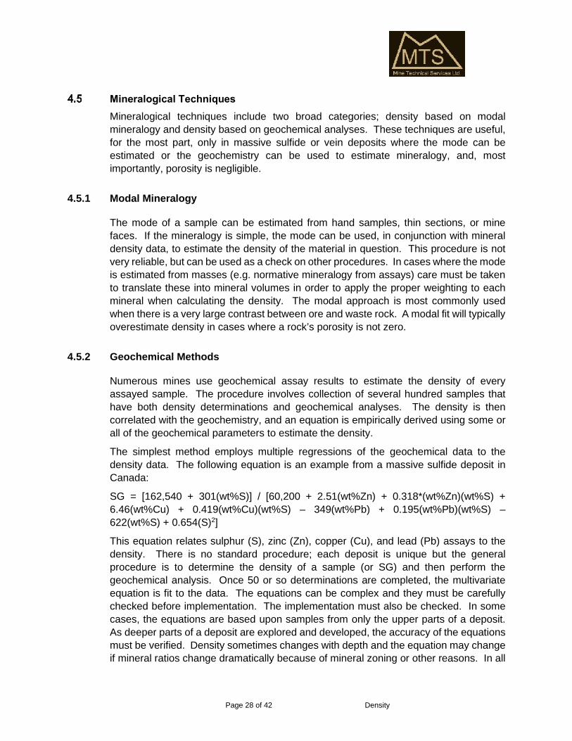
Mineralogical TechniquesMineralogical techniques include two broad categories; density based on modalmineralogy and density based on geochemical analyses. These techniques are useful,for the most part, only in massive sulfide or vein deposits where the mode can beestimated or the geochemistry can be used to estimate mineralogy, and, mostimportantly, porosity is negligible.
4.5.1 Modal Mineralogy
The mode of a sample can be estimated from hand samples, thin sections, or minefaces. If the mineralogy is simple, the mode can be used, in conjunction with mineraldensity data, to estimate the density of the material in question. This procedure is notvery reliable, but can be used as a check on other procedures. In cases where the modeis estimated from masses (e.g. normative mineralogy from assays) care must be takento translate these into mineral volumes in order to apply the proper weighting to eachmineral when calculating the density. The modal approach is most commonly usedwhen there is a very large contrast between ore and waste rock. A modal fit will typicallyoverestimate density in cases where a rock’s porosity is not zero.
4.5.2 Geochemical Methods
Numerous mines use geochemical assay results to estimate the density of everyassayed sample. The procedure involves collection of several hundred samples thathave both density determinations and geochemical analyses. The density is thencorrelated with the geochemistry, and an equation is empirically derived using some orall of the geochemical parameters to estimate the density.
The simplest method employs multiple regressions of the geochemical data to thedensity data. The following equation is an example from a massive sulfide deposit inCanada:
SG = [162,540 + 301(wt%S)] / [60,200 + 2.51(wt%Zn) + 0.318*(wt%Zn)(wt%S) +6.46(wt%Cu) + 0.419(wt%Cu)(wt%S) – 349(wt%Pb) + 0.195(wt%Pb)(wt%S) –622(wt%S) + 0.654(S)2]
This equation relates sulphur (S), zinc (Zn), copper (Cu), and lead (Pb) assays to thedensity. There is no standard procedure; each deposit is unique but the generalprocedure is to determine the density of a sample (or SG) and then perform thegeochemical analysis. Once 50 or so determinations are completed, the multivariateequation is fit to the data. The equations can be complex and they must be carefullychecked before implementation. The implementation must also be checked. In somecases, the equations are based upon samples from only the upper parts of a deposit.As deeper parts of a deposit are explored and developed, the accuracy of the equationsmust be verified. Density sometimes changes with depth and the equation may changeif mineral ratios change dramatically because of mineral zoning or other reasons. In all

Page 29 of 42 Density
cases, equations of this type must be continuously checked by comparing the equationto results from new sampling.
In the Sudbury Basin, specific gravity is calculated using the following (Vale Inco"Alcock") formula:
SGCALC= 100/(100/2.88+0.0166*Cu-0.1077*Ni-0.328*S)
MTS had the opportunity to check this formula against new SG data on multipleoccasions and found that it works well at any depth. There are local failures, but thosefailures are not typically significant.
Pycnometer and Related Procedures
4.6.1 Liquid Pycnometers
The pycnometer is a device used for measuring fluid density, also known as a specificgravity bottle. It uses working fluid such as water, acetone, or mercury (or even a gas)to find a volume. The name comes from the Greek puknos, a word meaning "density."Operation of a pycnometer is described in ISO 1183-1:2004.
A typical pycnometer consists of a flask with a close-fitting ground glass stopper with afine hole through it, allowing accurate measurement of volume. The flask is weighedempty, weighed after filling with water, and then weighed after filling with a liquid whosedensity is desired. The density of the liquid can easily be calculated. A sample in theform of a powder can be combined with water or a liquid of known density and put intothe pycnometer. The weight of the powder and the weight of the displaced liquid can bedetermined, and from them the density of the powder.
Pycnometers (ASTM, 1993) are not widely used in the mineral industry because theyprovide the density of the crushed or pulverized material, not the overall densityincluding porosity. Any porosity is destroyed when the samples are crushed orpulverized. If the rock porosity is zero, pycnometers provide acceptable density data,but porosity is rarely zero.
Pycnometers can also be used to determine the density of liquids. An importantexample is when brines are used as the immersion medium for density determinations;the density of the brine must be known. To determine the density of liquids in apycnometer, the following procedure, from Yoder and Leber (2003), is used:
The pycnometer that will be used in the density determination must first be calibrated:
Examine the pycnometer to be used. Unless the glassware is visibly dirty, donot clean it.
Place the pycnometer in a drying oven for fifteen to twenty minutes to insurethat all residual moisture has been removed from the glass. Let cool beforeweighing.

Page 30 of 42 Density
Weigh the empty dry pycnometer on an analytical balance and record themass. As you manipulate the pycnometer, be sure not to touch the glass withyour hands as residue and oils from your hands will impact the accuracy of themeasurement of the mass.
Fill the pycnometer with water of known temperature. Take the mass of thefilled pycnometer. The difference between the mass of the empty pycnometerand the pycnometer when it is full yields the mass of the liquid that is within thepycnometer. The literature value for the density of water at the temperatureobserved can be used to determine the volume of the pycnometer using theequation:
V = MH2O/ DH2O
Once the exact volume of the pycnometer being used is known, the density of theunknown fluid can now be determined.
After emptying the pycnometer, place it in the drying oven again for at least an hour.When all the moisture has been removed, allow the glassware to cool in adesiccator.
Weigh the dried, cooled pycnometer on an analytical balance.
Fill the pycnometer with the unknown fluid. Weigh the pycnometer containing thefluid and again take the difference between this mass and the mass of the emptypycnometer.
Knowing the mass of the unknown fluid and the volume of the pycnometer, thedensity of the unknown fluid can be calculated using D = M/V.
4.6.2 Gas Pycnometer
Gas pycnometers are commonly employed to determine density of powdered geologicalsamples. They are useful only for nonporous samples and will overestimate the densityof a sample by the amount of porosity in a sample. They therefore have no use forsamples that have significant porosity which severely limits their overall usefulness forgeological samples. In general, MTS is of the opinion that they should not be used todetermine density used to support Mineral Resource estimates.
The following discussion of the function of a gas pycnometer is from Wikipedia (2009).A gas pycnometer is a laboratory device used for measuring the density or moreaccurately the volume of solids, be they regularly shaped, porous or non-porous,monolithic, powdered, granular, or in some way comminuted, employing some methodof gas displacement and the volume:pressure relationship known as Boyle's Law. Thesimplest type of gas pycnometer (due to its relative lack of moving parts) essentiallyconsists of two chambers, one (with a removable gas-tight lid) to hold the sample and asecond chamber of fixed internal volume - referred to as the reference volume or addedvolume. The device additionally comprises a valve to admit a gas under pressure to one

Page 31 of 42 Density
of the chambers, a pressure measuring device - usually a transducer - connected to thefirst chamber, a valved pathway connecting the two chambers, and a valved vent fromthe second of the chambers. In practice the sample may occupy either chamber; that isgas pycnometers can be constructed such that the sample chamber is pressurized first,or such that it is the reference chamber that starts at the higher pressure. The workingequation of a gas pycnometer where the sample chamber is pressurized first is asfollows:
Equation 18: = +where Vs is the sample volume, Vc is the volume of the empty sample chamber (knownfrom a prior calibration step), Vr is the volume of the reference volume (again knownfrom a prior calibration step), P1 is the first pressure (i.e. in the sample chamber only)and P2 is the second (lower) pressure after expansion of the gas into the combinedvolumes of sample chamber and reference chamber.
Pycnometers (of any type) are recognized as density measuring devices; however, theyare in fact, devices for measuring volume only. Density is merely calculated as the ratioof mass to volume; mass being invariably measured on a discrete device, usually abalance. The volume measured in a gas pycnometer is that amount of three-dimensional space inaccessible to the gas used, i.e. that volume within the samplechamber from which the gas is excluded. Therefore the volume measured consideringthe finest scale of surface roughness will depend on the atomic or molecular size of thegas. Helium is most often prescribed as the measurement gas, not only is it of smallsize, it is also inert and the most ideal gas.
Miscellaneous MethodsNumerous other procedures have been used with variable success.
One method that has been used extensively is weighing core boxes. This method isonly applicable when core recovery is 100% and when the core diameter is veryuniform. Each box of core must be weighed and intervals of similar lithologies,alteration, etc. can then be added. Volume is calculated for the length of the intervaland average diameter of the core. Density is then the mass divided by the volume. Thismethod is not recommended, but it has been used successfully on a limited number ofprojects. It has also failed on a number of projects. It can be used as a procedure tocheck, in general, the results of more robust procedures.
With the advent of downhole probes that can be used in small diameter holes, it ispossible to use downhole tools to estimate the in situ density in many mineral explorationprojects. These procedures are not widely used in the mineral industry and where theyhave been used, in MTS’ experience, the data are not as reliable as data generated bymore traditional methods. Downhole densitometers must be recalibrated very frequentlyin order to assure reproducible results. Even then, accuracy can be compromised by

Page 32 of 42 Density
changes in the drill hole surface (rugosity) and shape. In situ measurements must alsobe corrected for moisture contents in order to obtain dry bulk density values for use inestimating the mineral resource. This is not to say that high-quality data cannot begenerated. A well calibrated downhole tool is capable of producing acceptable qualitydensity data in a uniform hole.
The CoreLokTM method has been successfully used by at least one mining operation.This method involves placing a sample in a plastic, puncture resistant bag, which isplaced inside another plastic bag. The sample is then placed in the chamber of theCoreLok™ apparatus. The apparatus will then be evacuated to 29.7 in. Hg. The sampleis then immersed in water and cut open. This allows water to enter the bag and fill allvoid spaces in the sample, saturating it. Once the water has completely filled the bag,the sample and bag are weighed under water. Knowledge of the weight of the bag,sample weight, and the combined weight of the bag and sample under water allows forcalculation of the maximum specific gravity.
Page 33 of 42 Density
5.0 QUALITY ASSURANCE-QUALITY CONTROL
As with any type of analytical method, density determinations must include anappropriate quality assurance-quality control program. When possible, a minimum of5%, preferably 10%, of the samples should be sent to a second laboratory for checkdensity determinations using a coated immersion procedure. The check laboratoryshould be chosen with the same care as for any check analytical facility. Comparisonsusing different procedures, i.e. performing the primary determination using a coatedimmersion procedure and checking 5% of the samples by measuring the length anddiameter of the core, are very useful checks and will normally identify problems.
Some operations employ round bar stock of known density, such as aluminum, ceramic,and steel rods, to check the calibration of equipment. These are highly recommended.
Examining drill recovery and RQD data may reveal which rock types are most likely tobe prone to systematic bias caused by biased sample selection. These can sometimesbe followed up by using a method, such as a large pit or normative mineralogy, to providea check on density. If the mean density of pieces selected for density is higher than themean by these other methods, there is a strong indication of a systematic error (bias),because the pit and modal methods should only match the density measurements if therock porosity is zero.
Biased density data are just as catastrophic to a resource estimate as biasedassay data. Extreme care must be taken to prevent or adjust biased data.

Page 34 of 42 Density
6.0 SPECIFIC RECOMMENDATIONS
Density Determinations on CoreThe following is a protocol for the determination of density for samples from most deposittypes. It is based largely on my experience.
6.1.1 Sample Selection
Samples will be selected by individual core loggers while the core is being logged.Because the grade of material present in an interval is not known when the core islogged, samples will be collected based on the core loggers identification of lithologicalboundaries. Sampling should begin near the collar of the hole and continue down thehole on 5 to 10 m intervals, respecting lithological boundaries. Shorter intervals areappropriate where complex ore-waste intervals or variable ore types are present. Thelength of the sample (along the centerline of the core) must be recorded along with therock type involved. There is some benefit to follow a set of rules for selecting core piecesfor density. Measurements, i.e., the samples are collected every 5 m, respectinglithological boundaries. The benefit is that every time a sample location is moved, i.e.,not on 5 m intervals, a reason can be logged, and this provides a gauge on the possibleselection bias for a particular rock type. Numerous shifts in sample locations are a redflag for selection bias for a particular rock type.
Samples should be whole core between 15 and 20 cm in length with shorter samplesselected only when longer samples are not available. Half-core is acceptable, but thesmaller the sample, the larger the relative error. Samples should be labeled and placedin a plastic bag by the core loggers. A tag or block must be placed in the core box toindicate where the sample was collected. That block should have the From-To interval,reason for sampling and sampler.
6.1.2 Sample Preparation
Samples should be carefully cleaned to remove any loose material attached to the core.This can be accomplished, for most samples, by placing the sample under running waterand gently brushing the sample. The sample should then be weighed and the “wet”mass recorded. The sample is then dried in an oven at temperatures no higher than105o ±5 o C. Higher temperatures can induce changes in the clay mineralogy and thusin the density of the rock in question. The samples should be dried for at least 12 hoursor until dry to ensure that all water has been removed from pores in the sample. Themost reliable drying method is to dry to constant weight. In this approach, the sample(usually while in the drying tray, which has a known weight) is weighed, returned to thedrying oven, and after some time, weighed again. The process is repeated until thereis no downward trend in the sample weight. Standards Association of Australia (1977a)and Standards Australia (2005a) discuss standard procedures for drying samples.

Page 35 of 42 Density
Note that some clay minerals lose hydration waters at temperatures below 50o C withsome significant losses above 75o C. Loss of hydration water may involve volumechanges so, clay-rich units should be carefully tested to determine whether, or not,drying at this temperature causes volume changes. If volume changes are apparent,the temperature should be reduced to 50o C and the time increased. The sample mustbe dried to dry no matter what temperature is used.
6.1.3 Analytical Procedure
Analysis of the sample begins by weighing and recording the weight of the dry samplein air. The sample is then dipped in a hot, molten wax of known density (Pure beeswaxhas a density of about 0.96; paraffin has a density of 0.4 to 0.9 depending on the sourceand specific composition.). Wax is highly flammable, no open flames or sparks shouldbe allowed within five meters of the container and the area should be ventilated and freeof other flammable material, in case the wax ignites. A fire extinguisher should be keptwithin easy reach. It is best if the temperature of the molten wax is only a few degreesabove its melting point. This will provide a thicker, more water-resistant coat, and lesswax will soak into the rock sample. Also, the low temperature will ensure the waxsolidifies rapidly when the sample is lifted out of the molten wax.
The weight of the waxed sample is then determined and recorded. This weight will allowthe density of the sample to be adjusted to compensate for the weight and buoyancy ofthe wax. In the case of paraffin or thin films, the effect of the mass is usually negligible,but some published methods stipulate this correction and best practice is to do thecorrection. The sample is then weighed while completely submerged in water (but notin contact with the bottom or side of the water vessel) and the weight recorded. Thetemperature of the water should be recorded to correct for temperature variations. Forcold water, this correction is also negligible. The density can then be calculated,correcting for the wax coating and temperature using the equations in Section 4.1.2.
6.1.4 Specific Case Protocols
In cases where the ore is contained in intensely argillized, clay-rich zones and inextremely broken zones (rubble) that are not amenable to the protocol in 8.1.3, thefollowing modifications to the protocol may be required.
Clay-rich Zones
Clay-rich zones should be handled similarly to the protocol above, but they cannot bedried prior to wax sealing and they are very fragile. The samples should be handled andcleaned gently; they will tend to disintegrate in water. These samples should be weighedwet and then immediately sealed in wax to retain their water content and to allow thesamples to be handled. The wet density should then be determined as above. Thesealed sample should then be opened and dried slowly at a temperature <35o C to

Page 36 of 42 Density
prevent melting and loss of wax which begins to melt at about 37o C. After the samplehas dried, the weight should be determined and recorded. This will allow the wet densityto be corrected to a dry density.
Broken (rubble) Zones
The density of broken (rubble) zones is extremely difficult to determine. A possiblesolution is to carefully measure the length of a broken zone and then weigh the corefrom that zone. This will allow for direct calculation of the density of the sample, but it isnecessary to have 100 percent core recovery and a very accurate measurement of thelength of the core. This may be accomplished by only using intervals between driller’sblocks, but there will always be uncertainty about the recovery.
Alternatively, it is possible to determine an adjustment factor to use for this type ofmaterial when solid (unbroken) material is adjacent to broken (rubble) zones bydetermining the density of the solid material volumetrically (using a pycnometer or othermethod) and decreasing the density by the porosity determined by saturating the driedsample (assuming that it does not disintegrate in water). Volumetric densitydeterminations are performed by cleaning, drying, and weighing the sample followed byplacing the sample in a container of water and very accurately measuring the volume ofthe water displaced by the sample. The density is then calculated by dividing the weightof the sample by the displaced volume of water.
This type of material is difficult, and no procedure will produce completely reliableresults. If the material is exposed at the surface, the most reliable determinations willbe produced by large-scale (mine scale) excavation techniques.
Vuggy Zones
Vuggy zones are common within ore zones and have distinctly lower bulk densities thanthe surrounding zones without vugs. These samples must be prepared somewhatdifferently than the non-vuggy samples. This type of material will be prepared by firstdrying the sample and then sealing the sample with wide packaging tape before it issealed in wax. The tape will insure that the decreased density due to vugs will beaccounted for in the final density determination. Density will then be determined usingthe coated immersion procedure.
Care must be used with this method because if the tape is too thin, it will deform whenthe sample is dipped in wax. If the tape is too thick, it will not faithfully follow the contourof the core. This is something of a last resort procedure that will provide useful, but nottotally reliable data.
A better method, if the core is competent is to carefully cut the ends of the samplesperpendicular to the core axis and then use calipers to measure the average length anddiameter of the core. This method is generally more reliable than the than the tape andimmersion method, but requires very competent core.

Page 37 of 42 Density
6.1.5 Additional Considerations
At the time of logging, we know very little about the details of metal distribution withinore zones. It is possible that most of the metal is contained in very small parts ofintervals or that it is evenly distributed within the interval. Because we require that a fulldiameter core be used for the density determination, the samples are typically pulledprior to assaying, and it is necessary to assay the sample after the density has beendetermined. Wax can be removed from the sample by boiling the sample in water (tapecan be difficult). The cleaned sample can then be assayed and the assay valueproportioned back into the interval if it is substantially above or below the valuedetermined for the interval. Recorded sample and interval lengths are necessary toperform this calculation.
Density Determinations of Unconsolidated or Soft Surface MaterialThe following procedure has been used effectively to determine the in situ bulk densityof near surface or underground, broken or soft rock.
6.2.1 Site Selection and Preparation
An appropriate site is selected based upon the rock units that need to be sampled. Thearea is cleaned and all loose material is removed so that undisturbed bedrock isexposed. The cleaned area should be on the order of 2 by 2 meters to insure that noloose material can contaminate the sample. The sample area should be carefullyleveled and surface irregularities minimized. The area should then be cleaned with abroom.
6.2.2 Surface Contour Volume Mapping
In order to obtain an accurate measurement of the rock sample volume, the irregularitiesof the surface need to be mapped. This is done by placing a wooden frame on thesurface of the rock and then very carefully leveling it. A thin plastic sheet is then placedin the frame and smoothed to minimize bunching of the plastic. Water is then used tofill the frame and the volume of the water is carefully measured and recorded. Thisprocedure is repeated three times to get an average volume. If any one of the volumemeasurements is significantly different than the other measurements, the process isrepeated until the volume is considered reliable.
6.2.3 Sample Excavation
The plastic liner is carefully removed from the frame and the outline of the inside of theframe is carefully marked on the rock, immediately below the frame. The outside of theframe is carefully marked to allow the frame to be reset over the hole after the sampleis excavated. The frame is removed and a portable rock saw is used to cut the sample

Page 38 of 42 Density
edges along the line marking the inside of the frame. Once a cut is begun, it must becompleted because loose material will fall into the hole and be removed if the groove isre-entered with the saw. Eight cuts, four for the outline, and four interior cuts allow foreasy removal of the sample. The position of the saw cuts and the number of cuts mustbe recorded. The sample is then carefully removed from the pit and placed in polysample bags.
6.2.4 Pit Volume Measurement
The frame is re-set over the pit, carefully oriented exactly as it was for the surfacemapping exercise. The pit is lined with plastic and filled with a known volume of wateruntil the water just overflows the frame. The volume of water is then recorded.
6.2.5 Sample Weighing and Drying
The sample bags are weighed and then placed in an oven to dry. The samples are thenre-weighed until a constant weight is achieved, possibly as much as several days to afew weeks to completely dry. The final weight of the sample is then recorded.
6.2.6 Density Calculations
The sample volume is calculated by subtracting the surface map volume from the pitvolume. The density is then the ratio of the sample weight to the sample volume. Thevolume lost to the saw cuts should be calculated and factored back into the final densitycalculation.
Saprolite and Other Weathered MaterialsDensity of saprolite and similar weathered materials can generally be determined usingthe procedure described in section 6.2, but MTS found the calibrated sand methoddescribed in section 4.4.2 to be more reliable if the material is exposed at the surface.It does; however, require significant manpower and time for each sample which limitsthe number of determinations that can be made in a day.
The slide hammer method is a very workable, useful procedure for exposed saprolite.The method is prone to small errors, but it is very easy and rapid. Multiple samples perhour are possible so small errors will tend to be hidden in the mass of data. As of dateof this report (April 2020), the slide hammer sampler is available from HumboldtConstruction Materials Testing Equipment (www.humboldtmfg.com/density-drive-sampler-2.html).
In some cases, saprolite density can be determined on drill core, but care must be takento preserve the integrity of the core. Saprolite, especially wet saprolite, is typically softand the core is easily distorted by rough handling. The most reliable density estimates

Page 39 of 42 Density
for saprolite combine extensive drill core sampling with a program of surface samplingusing the calibrated sand or slide hammer procedures.
Note that density in saprolite increases from the surface downward in a ratherpredictable way. That predictability can be used to model the density in saprolite ifsufficient data are available to produce the model. Recent work in saprolite-hosted golddeposits indicates that density can be effectively modeled using a linear regressionrelating percentage (proportion) of depth through the entire saprolite and density. Thistype of proportional model is easily constructed if the block modeling software candetermine proportions from a stack of blocks.

Page 40 of 42 Density
7.0 REFERENCES
Abzalov, M.Z., 2013, Measuring and Modelling of Dry Bulk Rock Density for MineralResource Estimation; Applied Earth Science (Trans. Inst. Min. Metall. B), v. 122,p. 16-29.
ASTM, 1986, Standard Test Methods for Bulk Density of Peat and Peat Products; ASTMDesignation D 4531 – 86 (Reapproved 2002); American Society for Testing andMaterials, West Conshohocken, PA, American Society for Testing and Materials,3 p.
ASTM, 1993, Standard Test Method for Specific Gravity of Soils; ASTM DesignationD854-92; American Society for Testing and Materials, Philadelphia, Pa, 4 p.(This is a pycnometer procedure).
ASTM, 1995, Standard Test Method for Bulk Density and Volume of Solid Refractoriesby Wax Immersion; ASTM Designation C914-95; American Society for Testingand Materials, Philadelphia, Pa, 3 p.
ASTM, 1996, Standard Test Methods for Absorption and Bulk Specific Gravity ofDimension Stone; ASTM Designation C97 – 96; American Society for Testingand Materials, West Conshohocken, PA, American Society for Testing andMaterials, 2 p.
ASTM, 2010, Standard Test Method for Density of Soil in Place by the Drive-CylinderMethod; ASTM Designation D2937 – 10; American Society for Testing andMaterials, West Conshohocken, PA, American Society for Testing and Materials,2 p.
ASTM, 2013, Standard Test Methods for Density of Soil and Rock in Place by the WaterReplacement Method in a Test Pit; ASTM Designation D5030/D5030M – 13a;American Society for Testing and Materials, West Conshohocken, PA, AmericanSociety for Testing and Materials, 14 p.
ASTM, 2014, Standard Test Methods for Specific Gravity of Soil Solids by WaterPycnometer; ASTM Designation D854 – 14; American Society for Testing andMaterials, West Conshohocken, PA, American Society for Testing and Materials,8 p.
ASTM, 2015a, Standard Test Method for Bulk Density and Volume of Solid Refractoriesby Wax Immersion – Designation: C914 – 09 (Reapproved 2015); AmericanSociety for Testing and Materials, Philadelphia, Pa., 3 p.
ASTM, 2015b, Standard Test Method for Bulk Specific Gravity and Density ofCompacted Bituminous Mixtures using Coated Samples; ASTM DesignationD1188 – 07 (Reapproved 2015); American Society for Testing and Materials,West Conshohocken, PA, American Society for Testing and Materials, 4 p.

Page 41 of 42 Density
ASTM, 2016a, Standard Test Method for Bulk Density and Volume of Solid Refractoriesby Wax Immersion; ASTM Designation C914-95 (Reapproved 2015); AmericanSociety for Testing and Materials, Philadelphia, Pa, 3 p.
ASTM, 2016b, Standard Test Methods for Density of Soil and Rock in Place by the SandReplacement Method in a Test Pit; ASTM Designation D4914/D4914M – 16;American Society for Testing and Materials, West Conshohocken, PA, AmericanSociety for Testing and Materials, 16 p.
Balco, G. and Stone, J.O., 2003, Measuring the Density of Rock, Sand, Till, etc.; UWCosmogenic Nuclide Laboratory, methods and procedures;http://depts.washington.edu/cosmolab/chem/density_method.pdf, 6 p, accessed8 August 2016.
Hurlbut, C.S., Jr., 1971, Dana’s Manual of Mineralogy; New York, John Wiley & Sons,Inc., p. 130-136.
InstroTek, 2001, Maximum specific gravity, Gmm, using the CoreLokTM Method;InstroTech, Inc., promotional information circular, 2p.
Lipton, I.T., 2001, Measurement of Bulk Density for Resource Estimation; in, Edwards,A.C., ed., Mineral Resource and Ore Reserve Estimation – The AusIMM Guideto good Practice, The Australasian Institute of Mining and Metallurgy, p. 57-66).
McKinstry, H.E., 1948, Mining Geology; New York, Prentice-Hall, Incorporated, 680 p.
Parrish, I.S., 1993, Tonnage Factor – a matter of some gravity; Mining Engineering,October 1993, p. 1268-1271.
Sheldrick, B.H., ed., 1984. Analytical methods manual 1984; Land Resource ResearchInstitute, Research Branch, Agriculture and Agri-Food Canada;http://sis.agr.gc.ca/cansis/publications/manuals/1984-30/84-029-bulk-density-core-method.pdf, 3p., accessed 8 August 2016.
Standards Association of Australia, 1977b, AS 1289.B1.1-1997 Determination of themoisture content of a soil – oven drying method (standard method); in, StandardsAssociation of Australia, Australian Standard Methods of Testing Soil forEngineering Purposes, 2p.
Standards Association of Australia, 1977b, AS 1289.E3.1-1977 Determination of thefield dry density of a soil – sand replacement method using a sand-cone pouringapparatus: Standards Association of Australia, Australian Standard Methods oftesting soil for Engineering Purposes Part E – Soil compaction and density tests,3 p.
Standards Australia, 2005a, Methods of testing rocks for engineering purposes Part1.1.1: Rock moisture content tests – Determination of moisture content of rock –Oven drying method (standard method) (Revision of AS4133.1.1.1-1993);

Page 42 of 42 Density
Standards Australia Combined Postal Ballot/Draft Public Comment AustralianStandard, 2p. (This is a draft discussion of revisions to the 1993 standard andis indicated as do not use as standard, but the procedures are good in that it issimilar to the 1993 standard.)
Standards Australia, 2005b, Method of testing for engineering purposes Part 2.1.1: Rockporosity and density tests – Determination of rock porosity and dry density –Saturation and caliper techniques (Revision of AS 4133.2.1.2-1993; StandardsAustralia Combined Postal Ballot/Draft Public Comment Australian Standard,3p. (This is a draft discussion of revisions to the 1993 standard and is indicatedas do not use as standard, but the procedures are good in that it is similar to the1993 standard.)
Standards Australia, 2005c, Method of testing for engineering purposes Part 2.1.2: Rockporosity and density tests – Determination of rock porosity and dry density –Saturation and buoyancy techniques (Revision of AS 4133.2.1.1-1993;Standards Australia Combined Postal Ballot/Draft Public Comment AustralianStandard, 4p. (This is a draft discussion of revisions to the 1993 standard andis indicated as do not use as standard, but the procedures are good in that it issimilar to the 1993 standard.)
United States Department of the Interior, 1989, Procedure for Determining unit weightof soils in-place by the water replacement method in a test pit; United StatedDepartment of the Interior Bureau of Reclamation, USBR 7221-89, p. 1172-1187.
Yoder, C. and Leber, P., 2003, Determination of Density; Online Laboratory Tutorials,Franklin and Marshall College, 3 p.(http://wulfenite.fandm.edu/labtech/density.htm).