Embed Size (px)
Citation preview
ENZFELDER GmbH
Power transmission
and
lifting engineering
RO
FREN Bevel Gear Box
Type H and K
History
1969 Mr. Enzfelder established a job shop in Vienna. Equipped with some machinery, the Enzfelder Company manufactured machine parts according to drawings. Within one year the number of employees rose to 3. The Enzfelder company started manufacturing threaded spindles and nuts according to drawings. Then the range of manufacturing was enlarged by toothed wheels, screw wheels and endless screws according to drawings. 1974 The company including the complete manufacture was relocated to Enzesfeld. 1975 The manufacture of spindle gears was launched. The company’s experience in the manufacture of trapezoid-threaded spindles, nuts, worm gear pairs and casings was a valuable basis for the construction. After many tests, the serial production of spindle gears was launched one year later. The result was a product characterized by a first-rate price-performance ratio. The product was distributed by dealers all over Europe. 1981 The planning and construction of small hydropower plants was launched to replace diesel generators. Environmental protection was not really a topic at that time, however, and the production was stopped in 1986. 1989 The Enzfelder GesmbH company replaced the Franz Enzfelder Company. 1990 Scissor-type lifting platforms and cable winches were added to the delivery program. 1991 Resilient spacer shafts were tested and added to the production range. At the same time, the telescopic spindle gear was developed. A patent for this principle was applied for and issued. 1993 The sale of spindle gears under their own name was launched and presented for the first time at the Hannover industrial fair. We have been approached with a variety of tasks and have provided solutions according to the customers’ needs ever since. 1994 In cooperation with our customers we produced the first bevel gears to specification. 1995 Spindle bearing arrangements were designed and included in the standard program. 1996 The Enzfelder company produced planet gear to specification for the first time. 1998-1999 The standard programs were enlarged. Additionally, bevel gears are manufactured in a standard design. 2000 The development of electric cylinders in standard design for very high loads (5-1000kN) was started. At the same time the telescopic spindle gears were refined to save the customer the guiding and locking devices. Since that time we have been able to offer telescopic cylinders, too. 2001 The development of electric cylinders was completed, and these cylinders were added to the standard program. At the same time the development and fabrication of cubic spindle gears for lifting loads between 2.5 and 150kN was started. These gears were added to the standard program as well. 2002 were extended and optimized the series of the electric cylinders. Further we provide an electronic 2D-3D product catalogue of the spindle gears, it makes it possible to integrate our products into your system. 2002-2003 We putted our new assembling and packaging hall, beside the manufacturing hall, in operation 2003 We increased our machinery by buying a CNC machine tool with 7 axes, brand AXA. That new CNC machine allows a precise machining of the screw jack housings in only two clamping. 2003-2004 The engineering started to use new 3-D CAD software, Solid Edge. That software enables our customers to integrate easily our drawings. 2004 We opened a sales office in France. 2004-2005 We started to design the high performance screw jacks HSG and we created a range of 10 different sizes. 2005 First participation to an exhibition in France: INDUSTRIE 2005 at Lyon. 2005-2006 We started to design a new range of telescopic screw jacks TSGLR. Today, these new telescopic screw jacks, with a more compact design, are used in the stage industry, in the aircraft industry, on train lifting equipments and in machine building. 2008 We replaced the tread grinding machine by a new CNC thread grinding machine, brand Mikromat. In the past years we solved problems of motive power engineering and lifting for our customers. We searched and found the optimal solution for each case and manufactured at the best possible price/performance ratio. Delivery 01-2009


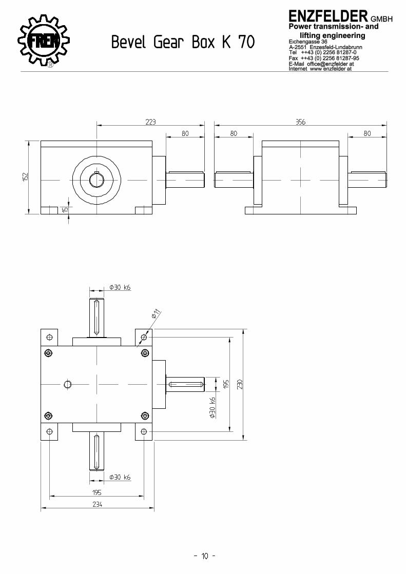
In our lifting systems 2 types of bevel gears can be used. The types H and the types K. Both of them have been used during many years. On the great diverity of the intonation has been considert, while planing and constructioning them. The gears are built very compact and they have a very small weight. Both series can be delivered also with flange or hollow shaft. It is possible, too to deliver our gears in stainless type. If you need any other type or size, which you can not fing in our catalogue, do not hesitate to cantact us. Type H The compact nad stable construction guarantees highest power an smallest dimension and little weight. Because of the lubrication for duration of life, dependend on the gear-size, the gears are maintenance free, under normal application. The gear housing is made of casting GGG50. The storage of the shafts is made by taper roller bearings which guarantees a long duration of life. The toothing is a Glearson helix toothing for highest torques. Because of the contact refelction-optimized assembly mounting, an equal tooth load can be reached. Through this measures a very high efficiency of 98° can be reached. The serie H embraces 8 sizes from type H075 to type H280. The gear reductions are 1:1, 1,5:1, 2:1, 3:1, 4:1 and 5:1. The entrance number of revolution can go up to 6000RpM, dependend on the size. Type K The bevel gears are helix toothed and hardened. The gear housing can be made of Alu, steel or casting GGG50. The storage is a well dimensioned bearing. The advantage of the type K are the gearfeet which are casted in one piece with the housing, to allow a simply fitting, because it is possible to fit with screws fromthe above side. The gears are filled with oil or ghrease. The serie contents aof 4 sizes from type K80 to type K70. The effeciency from this serie goes up from 80% to 85%. It is possible to deliver gears from two shafts to four shafts. The gear reductions are 1:1, 2:1 and 3:1. Mountain and Operating Instruction The operating and mounting instructions you can find enclosed each delivery.

i Title Unit H75 H90 H110 H140 H170 H210 H240 H280Nominal torque M2 45 78 150 360 585 1300 2150 3200max. permissible torque M2* 68 117 225 540 878 1950 3225 4800Nominal torque M2 45 78 150 360 585 1300 2150 3200max. permissible torque M2* 68 117 225 540 878 1950 3225 4800Nominal torque M2 42 68 150 330 544 1220 2010 3050max. permissible torque M2* 63 102 225 495 816 1830 3015 4575Nominal torque M2 33 54 120 270 450 1020 1650 2850max. permissible torque M2* 50 81 180 405 675 1530 2475 4275Nominal torque M2 28 52 100 224 376 860 1410 2300max. permissible torque M2* 42 78 150 336 564 1290 2115 3450Nominal torque M2 25 40 85 196 320 740 1210 2000max. permissible torque M2* 38 60 128 294 480 1110 1815 3000max. rpm at input rpm 6500 5500 4500 3500 3000 2200 2000 1700
arcmin 6 bis 15 6 bis 14 6 bis 13 6 bis 13 6 bis 12 6 bis 12 6 bis 12 6 bis 11arcmin 5 bis 6 4 bis 6 4 bis 6 3 bis 6 3 bis 6 3 bis 6 3 bis 6 3 bis 6
Permissible Radial LoadInput Shaft d1Permissible Radial LoadOutput Shaft d1Permissible Axial LoadInput Shaft d1Permissible Axial LoadOutput Shaft d1
%db(A) 70 74 76 77 78 80 82 83
kg 4,5 8 13 22 38,5 71 103,5 155h
Running Noise at 1500rpm, Partial Load
2:1
-30°C up to 100°C
> 15.000
at 2% max Load standard output backlashat 2% max Load minmal output backlash
> 98
Operating TemperatureLubricationService Live
Weight
9.000
Forc
e co
ntac
t poi
nt is
mid
th
of s
haft
Nm
5.250 7.500
18.000
650 1.000 1.750
Nm
Nm
Nm
Nm
Nm
1:1
1,5:1
2.250 3.000N 550 800 1.250
N 450 2.500 4.250 5.500 7.500
4.500 6.000 10.500 15.000N 1.100 1.600 2.500
5.000 8.500 11.000 15.000900
up to and including H140: Synthetic Lubrication Oil, ISO VG 150
Efficiency at max. Load
3:1
4:1
5:1
N 1.300 2.000 3.500

i Title Einheit K32 K52,5 K61,5 K70
Nominal torque M2 7,5 35 63 232max. permissible torque M2* 11,25 52,5 94 348Nominal torque M2 5,8 34 68 216max. permissible torque M2* 8,7 51 102 324Nominal torque M2 - - - 162max. permissible torque M2* - - - 243Nominal torque M2 6,6 30 62 -max. permissible torque M2* 10 45 93 -
rpm 3000 1500 2000 1500arcmin 30 30 30 30
Permissible Radial LoadInput Shaft d1Permissible Radial LoadOutput Shaft d1Permissible Axial LoadInput Shaft d1Permissible Axial LoadOutput Shaft d1
AL%
db(A) 75 78 78 78kg 1,1 5,5 9 27h
N
max. rpm at input
Temperature
Running noiseWeight
Service LifeLubrication
at 2% max Load standard output backlash
Forc
e co
ntac
t poi
nt is
mid
th
of s
haft
Material
500 1.200
1.650N
2,5:1
3:1
N 200
635
ST or GG
2:1
Nm
405
Nm
Nm
N
100
80
-30°C up to 100°C
> 10000
> 80Efficiency
Grease or Oil
160 290
1:1 Nm
250 800
40 50 100
100
Type K32 K52,5 K61,5 K70 H75 H90 H110 H140 H170 H210 H240 H280Thermal Performance Limit (Kw) 2,3 4 7,9 12 5,5 7,4 10,8 16,1 23,4 28,6 45,3 60,3
Duty Cycle per Hour % 100 80 60 40 20Factor 1 1,2 1,4 1,6 1,8
Duty Cycle per Hour % 100 80 60 40 20Factor 1 1,2 1,4 1,6 1,8

Performance P [kW] at ninput [rpm] (Pinput ? Poutput at h > 98%)
Gear Ratio i Speed ninput; noutput = ninput : n
Output Torque Moutput [Nm] = (9550 x P output ): n output
Output Torque Moutput < Nominal Torque M2Nominl
Maximum Output- Maximum permissible
torque Moutput max < Outputtorque M2max
at up to 10 start-ups per Minute
Maximum Output Torque Moutput max < Nominal Torque M2nominal at up to 60 start-ups per Minute
Maximum values for start numbers ranging between 10 to 60 start-ups will be interpolated
Speed ninput < Speed n1max
Performance P < Thermal Performance Limit Ptherm (20°C, 100% ED)
Thermal performance limit changes with deviating temperature values and duty times according to factor indicated in the table on page 5
radial and axial Shaft Loads < permissible values FQ1, FQ2, FA1, FA2
From table on page 4 and 5 (Force contact point is midth of shaft, to realize higher values, a re-calculation mast be made Example: given: n1 = 3000 rpm Distributiongearbox n2 = 750 rpm
P = 15,5 kW ED = 100% Ambient temperature = 20°C
Selection: i = n1 / n2 i = 3000 rpm : 750 rpm
i = 4:1
M2 = 9550xP / n2 M2 = 9550 x 15,5 : 750 M2 = 197,37 Gear box H140 4:1
M2exist < M2nominal M2exist 197,37 Nm < M2nominal 224 Nm n1exist < n1max 3000 rpm < 3500 rpm max Pexist < Ptherm P = 15,5 kW < Ptherm 16,1 kW
Selected: H140 4:1


FREN Spindle gear for lifting, lowering, pulling,
pushing, sluing, or rotating
Forces up to 3000kN
Lifts up to 10000mm
FREN Electric cylinders for lifting, lowering, pulling,
pushing, sluing, or rotation
Forces up to 1000kN
Lifts up to 2500mm
FREN Bevel gears ‘K’ and Bevel gears cubic ‘H’for deflecting imput shaftsSpeeds up to 6500U/minTorques up to 5200Nm
FREN Resilient cardan shafts for transmitting
torques with assembling inaccuracies
Angles up to 3°
Torques up to 500Nm
FREN Telescopic gears and telescopic cylinders
for lifting, lowering, pulling, pushing
Forces up to 1000kN
Lifts up to 10000mm
FREN Planet gears in special designs for
reducing speeds and increasing torques
Gear reduction 1,5:1 up to 1500:1
Torques up to 1000Nm
FREN Scissor-type lifting platforms for lifting and lowering
including a wide range of accessories
Forces up to 500kN
Lifts up to 5000mm
FREN Cable winches for lifting, lowering, pulling
or sluing
Forces up to 300kN
Lifts up to 100000mm
Delivery programm