Embed Size (px)
Citation preview
OPUS:
Online Positioning User Service
http://www.ngs.noaa.gov/OPUS/
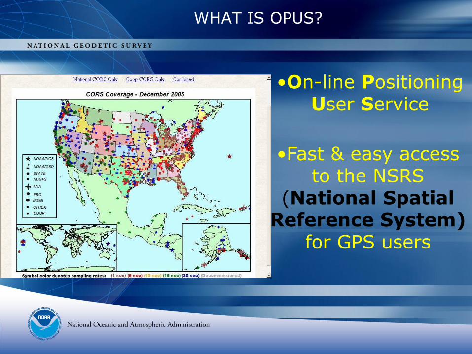
WHAT IS OPUS?
•On-line Positioning User Service
•Fast & easy access to the NSRS
(National Spatial Reference System)
for GPS users
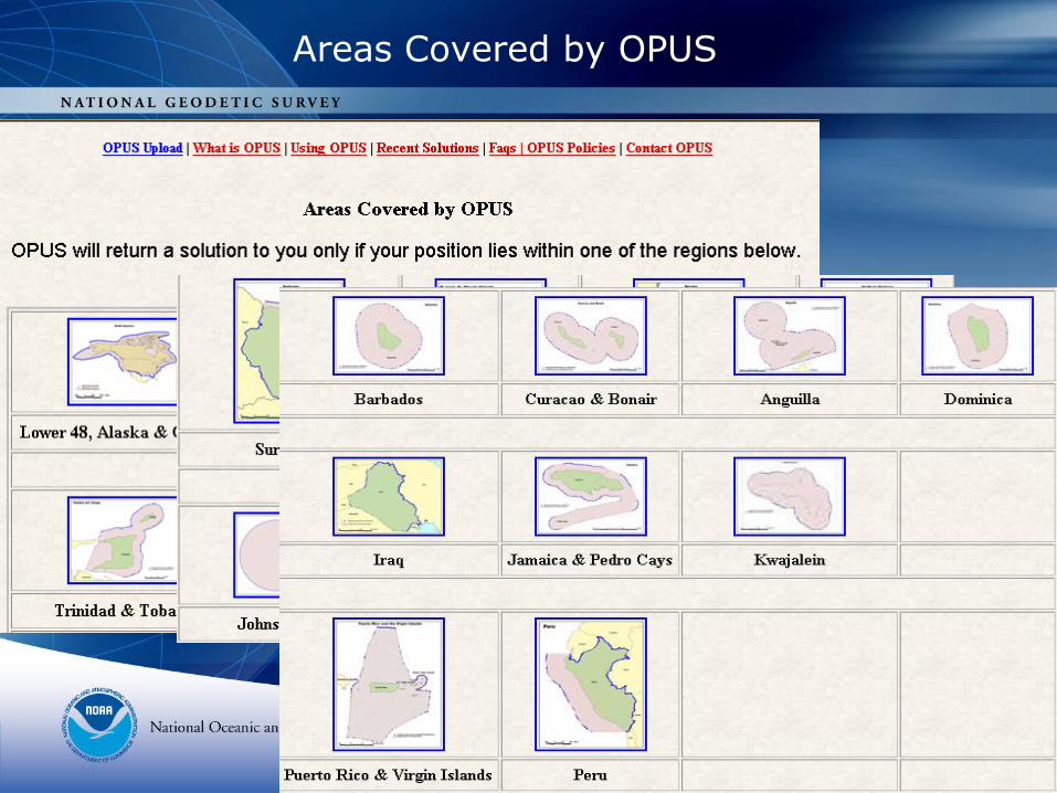
Areas Covered by OPUS
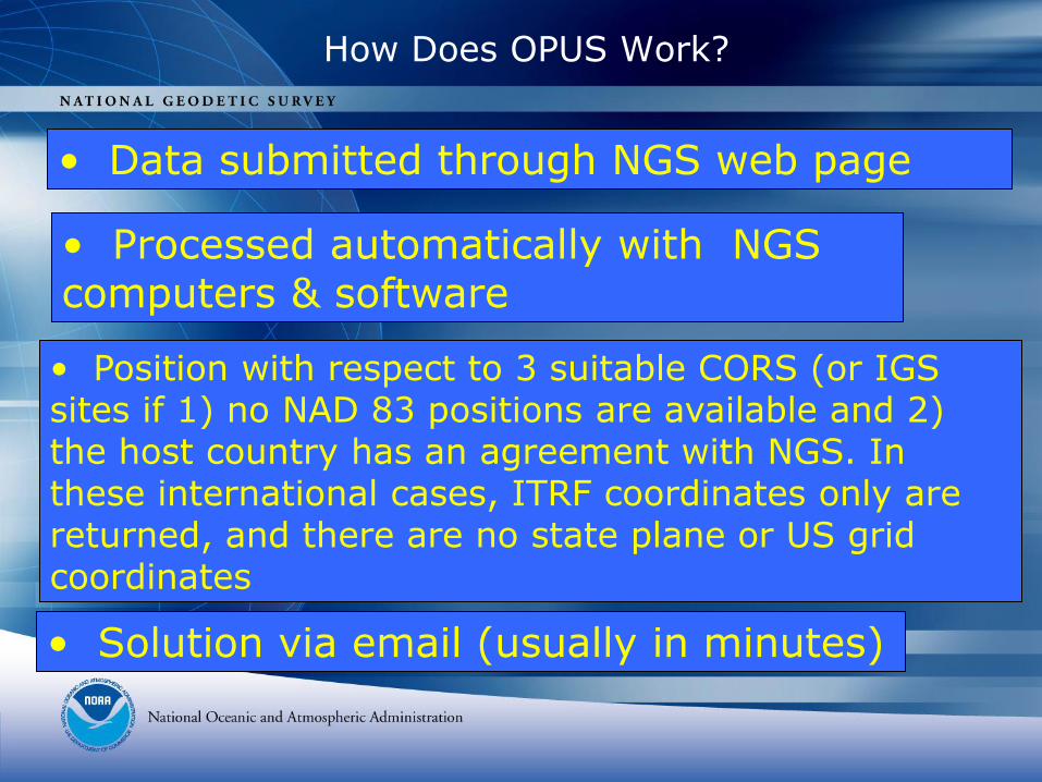
How Does OPUS Work?
• Data submitted through NGS web page
• Processed automatically with NGS computers & software
• Position with respect to 3 suitable CORS (or IGS sites if 1) no NAD 83 positions are available and 2) the host country has an agreement with NGS. In these international cases, ITRF coordinates only are returned, and there are no state plane or US grid coordinates
• Solution via email (usually in minutes)
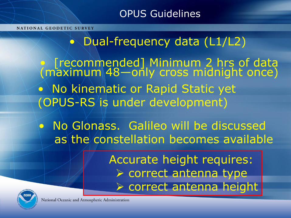
OPUS Guidelines
• Dual-frequency data (L1/L2)
• [recommended] Minimum 2 hrs of data (maximum 48—only cross midnight once)
• No kinematic or Rapid Static yet (OPUS-RS is under development)
• No Glonass. Galileo will be discussed as the constellation becomes available
Accurate height requires: correct antenna type correct antenna height
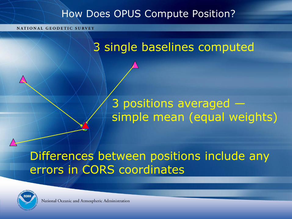
How Does OPUS Compute Position?
3 single baselines computed
3 positions averaged —simple mean (equal weights)
Differences between positions include any errors in CORS coordinates
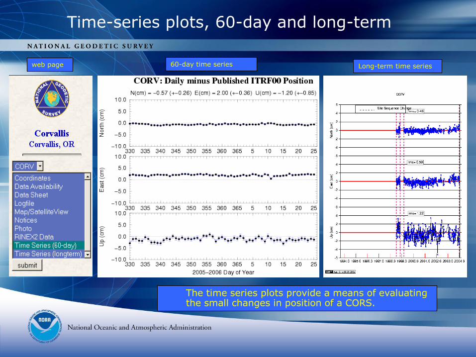
Time-series plots, 60-day and long-term
web page 60-day time series Long-term time series
The time series plots provide a means of evaluating the small changes in position of a CORS.
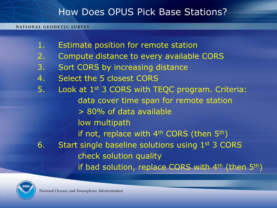
How Does OPUS Pick Base Stations?
1. Estimate position for remote station
2. Compute distance to every available CORS
3. Sort CORS by increasing distance
4. Select the 5 closest CORS
5. Look at 1st 3 CORS with TEQC program. Criteria:
data cover time span for remote station
> 80% of data available
low multipath
if not, replace with 4th CORS (then 5th)
6. Start single baseline solutions using 1st 3 CORS
check solution quality
if bad solution, replace CORS with 4th (then 5th)
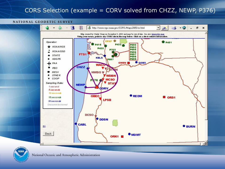
CORS Selection (example = CORV solved from CHZZ, NEWP, P376)
Quick Link to OPUS
from NGS Home Page
www.ngs.noaa.gov
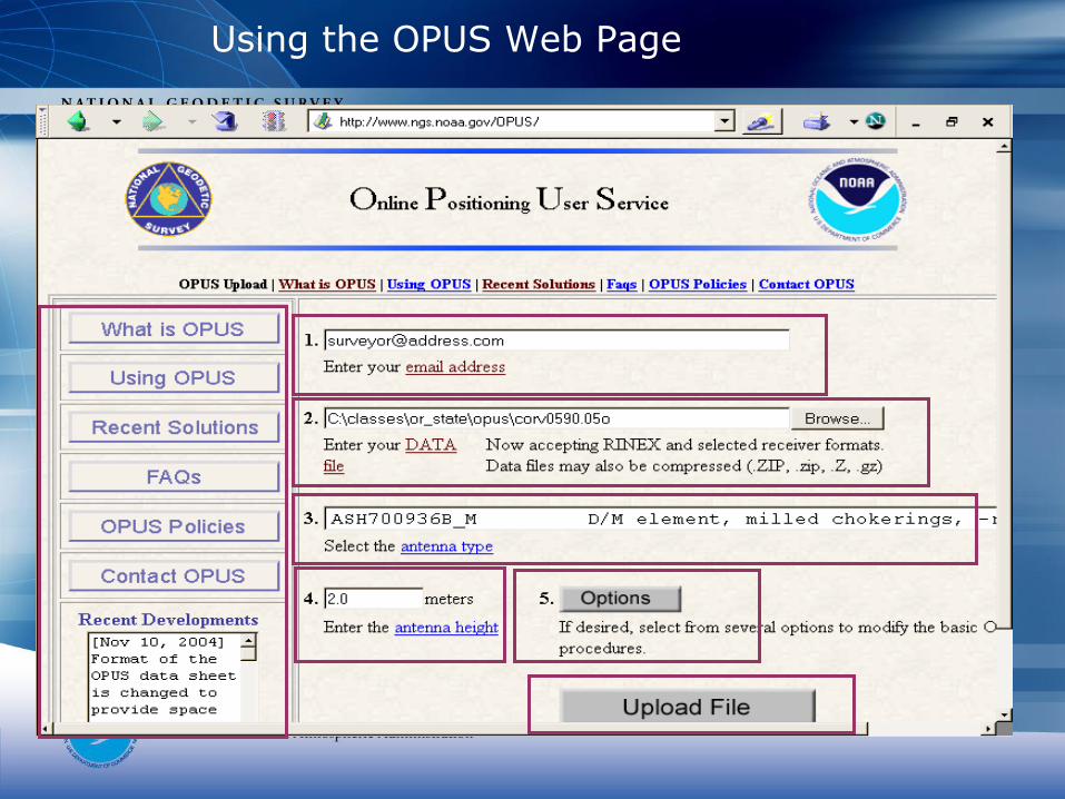
Using the OPUS Web Page
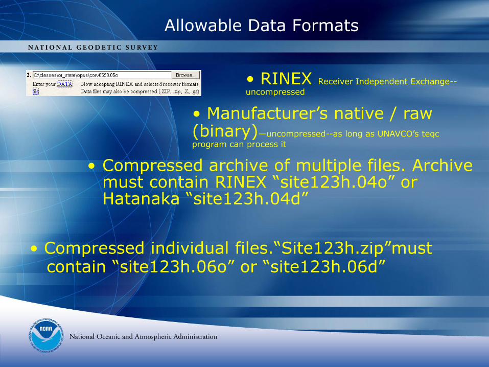
Allowable Data Formats
• Compressed archive of multiple files. Archive must contain RINEX “site123h.04o” or Hatanaka “site123h.04d”
• Compressed individual files.“Site123h.zip”mustcontain “site123h.06o” or “site123h.06d”
• Manufacturer’s native / raw (binary)—uncompressed--as long as UNAVCO’s teqc
program can process it
• RINEX Receiver Independent Exchange--
uncompressed
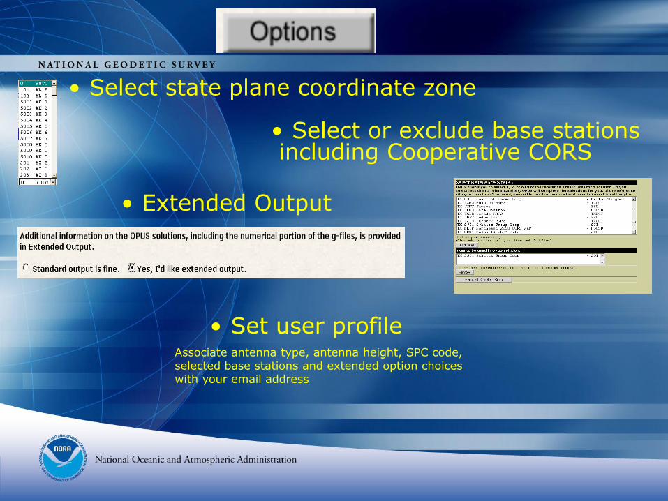
• Select or exclude base stationsincluding Cooperative CORS
• Select state plane coordinate zone
• Extended Output
• Set user profileAssociate antenna type, antenna height, SPC code, selected base stations and extended option choices with your email address
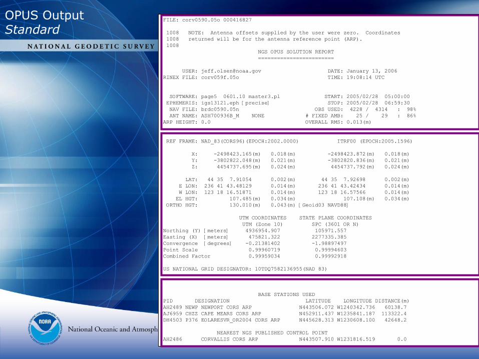
FILE: corv0590.05o 000416827
1008 NOTE: Antenna offsets supplied by the user were zero. Coordinates
1008 returned will be for the antenna reference point (ARP).
1008
NGS OPUS SOLUTION REPORT
========================
USER: [email protected] DATE: January 13, 2006
RINEX FILE: corv059f.05o TIME: 19:08:14 UTC
SOFTWARE: page5 0601.10 master3.pl START: 2005/02/28 05:00:00
EPHEMERIS: igs13121.eph [precise] STOP: 2005/02/28 06:59:30
NAV FILE: brdc0590.05n OBS USED: 4228 / 4314 : 98%
ANT NAME: ASH700936B_M NONE # FIXED AMB: 25 / 29 : 86%
ARP HEIGHT: 0.0 OVERALL RMS: 0.013(m)
REF FRAME: NAD_83(CORS96)(EPOCH:2002.0000) ITRF00 (EPOCH:2005.1596)
X: -2498423.165(m) 0.018(m) -2498423.872(m) 0.018(m)
Y: -3802822.048(m) 0.021(m) -3802820.836(m) 0.021(m)
Z: 4454737.695(m) 0.024(m) 4454737.792(m) 0.024(m)
LAT: 44 35 7.91054 0.002(m) 44 35 7.92698 0.002(m)
E LON: 236 41 43.48129 0.014(m) 236 41 43.42434 0.014(m)
W LON: 123 18 16.51871 0.014(m) 123 18 16.57566 0.014(m)
EL HGT: 107.485(m) 0.034(m) 107.108(m) 0.034(m)
ORTHO HGT: 130.010(m) 0.043(m) [Geoid03 NAVD88]
UTM COORDINATES STATE PLANE COORDINATES
UTM (Zone 10) SPC (3601 OR N)
Northing (Y) [meters] 4936954.907 105971.557
Easting (X) [meters] 475821.322 2277335.385
Convergence [degrees] -0.21381402 -1.98897497
Point Scale 0.99960719 0.99994603
Combined Factor 0.99959034 0.99992918
US NATIONAL GRID DESIGNATOR: 10TDQ7582136955(NAD 83)
BASE STATIONS USED
PID DESIGNATION LATITUDE LONGITUDE DISTANCE(m)
AH2489 NEWP NEWPORT CORS ARP N443506.072 W1240342.736 60138.7
AJ6959 CHZZ CAPE MEARS CORS ARP N452911.437 W1235841.187 113322.4
DH4503 P376 EOLARESVR_OR2004 CORS ARP N445628.313 W1230608.100 42648.2
NEAREST NGS PUBLISHED CONTROL POINT
AH2486 CORVALLIS CORS ARP N443507.910 W1231816.519 0.0
OPUS OutputStandard
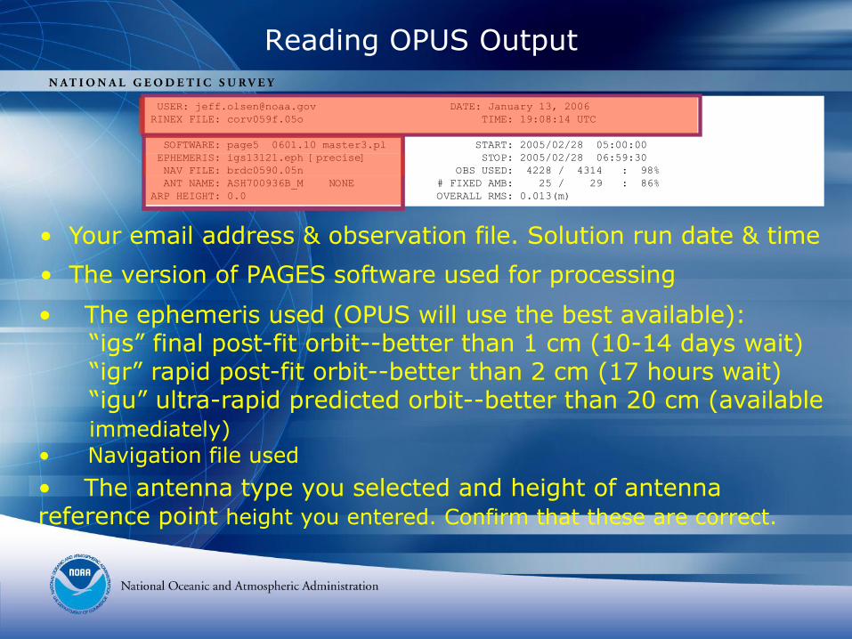
USER: [email protected] DATE: January 13, 2006
RINEX FILE: corv059f.05o TIME: 19:08:14 UTC
SOFTWARE: page5 0601.10 master3.pl START: 2005/02/28 05:00:00
EPHEMERIS: igs13121.eph [precise] STOP: 2005/02/28 06:59:30
NAV FILE: brdc0590.05n OBS USED: 4228 / 4314 : 98%
ANT NAME: ASH700936B_M NONE # FIXED AMB: 25 / 29 : 86%
ARP HEIGHT: 0.0 OVERALL RMS: 0.013(m)
Reading OPUS Output
• The version of PAGES software used for processing
• The antenna type you selected and height of antenna reference point height you entered. Confirm that these are correct.
• The ephemeris used (OPUS will use the best available):“igs” final post-fit orbit--better than 1 cm (10-14 days wait) “igr” rapid post-fit orbit--better than 2 cm (17 hours wait)“igu” ultra-rapid predicted orbit--better than 20 cm (availableimmediately)
• Navigation file used
• Your email address & observation file. Solution run date & time
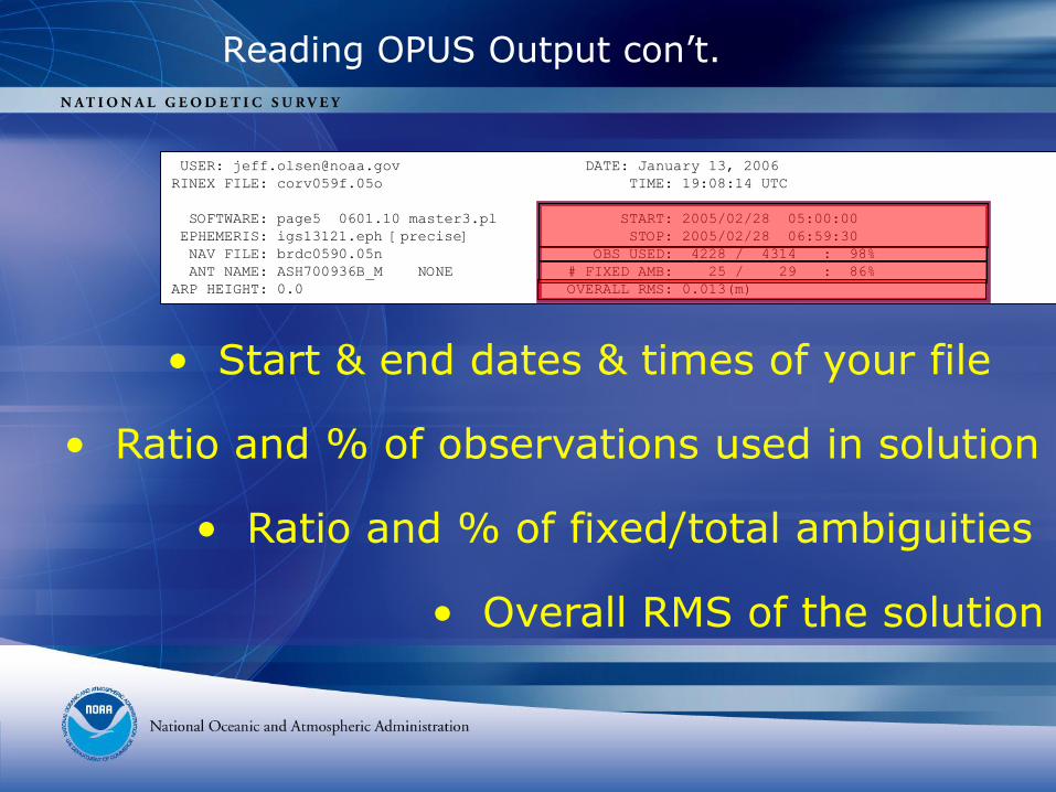
USER: [email protected] DATE: January 13, 2006
RINEX FILE: corv059f.05o TIME: 19:08:14 UTC
SOFTWARE: page5 0601.10 master3.pl START: 2005/02/28 05:00:00
EPHEMERIS: igs13121.eph [precise] STOP: 2005/02/28 06:59:30
NAV FILE: brdc0590.05n OBS USED: 4228 / 4314 : 98%
ANT NAME: ASH700936B_M NONE # FIXED AMB: 25 / 29 : 86%
ARP HEIGHT: 0.0 OVERALL RMS: 0.013(m)
• Start & end dates & times of your file
• Ratio and % of observations used in solution
• Ratio and % of fixed/total ambiguities
• Overall RMS of the solution
Reading OPUS Output con’t.
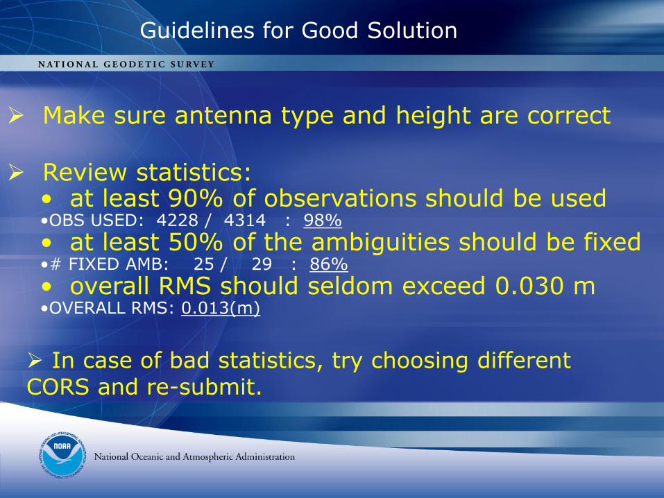
Guidelines for Good Solution
Make sure antenna type and height are correct
Review statistics:• at least 90% of observations should be used•OBS USED: 4228 / 4314 : 98%
• at least 50% of the ambiguities should be fixed•# FIXED AMB: 25 / 29 : 86%
• overall RMS should seldom exceed 0.030 m•OVERALL RMS: 0.013(m)
In case of bad statistics, try choosing different CORS and re-submit.
REF FRAME: NAD_83(CORS96)(EPOCH:2002.0000) ITRF00 (EPOCH:2005.1596)
X: -2498423.165(m) 0.018(m) -2498423.872(m) 0.018(m)
Y: -3802822.048(m) 0.021(m) -3802820.836(m) 0.021(m)
Z: 4454737.695(m) 0.024(m) 4454737.792(m) 0.024(m)
LAT: 44 35 7.91054 0.002(m) 44 35 7.92698 0.002(m)
E LON: 236 41 43.48129 0.014(m) 236 41 43.42434 0.014(m)
W LON: 123 18 16.51871 0.014(m) 123 18 16.57566 0.014(m)
EL HGT: 107.485(m) 0.034(m) 107.108(m) 0.034(m)
ORTHO HGT: 130.010(m) 0.043(m)
• Reference frames. Epochs • Position, xyz
• Peak-peak errors, xyz (range, max-min)
• Peak-peak errors may vary between NAD83 & ITRF
• Orthometric ht. is based on current geoid model
Reading OPUS Output con’t.Solution/Coordinates
[Geoid03 NAVD88]
• Position, lat / long / eh / oh • Peak-peak for lat/long etc
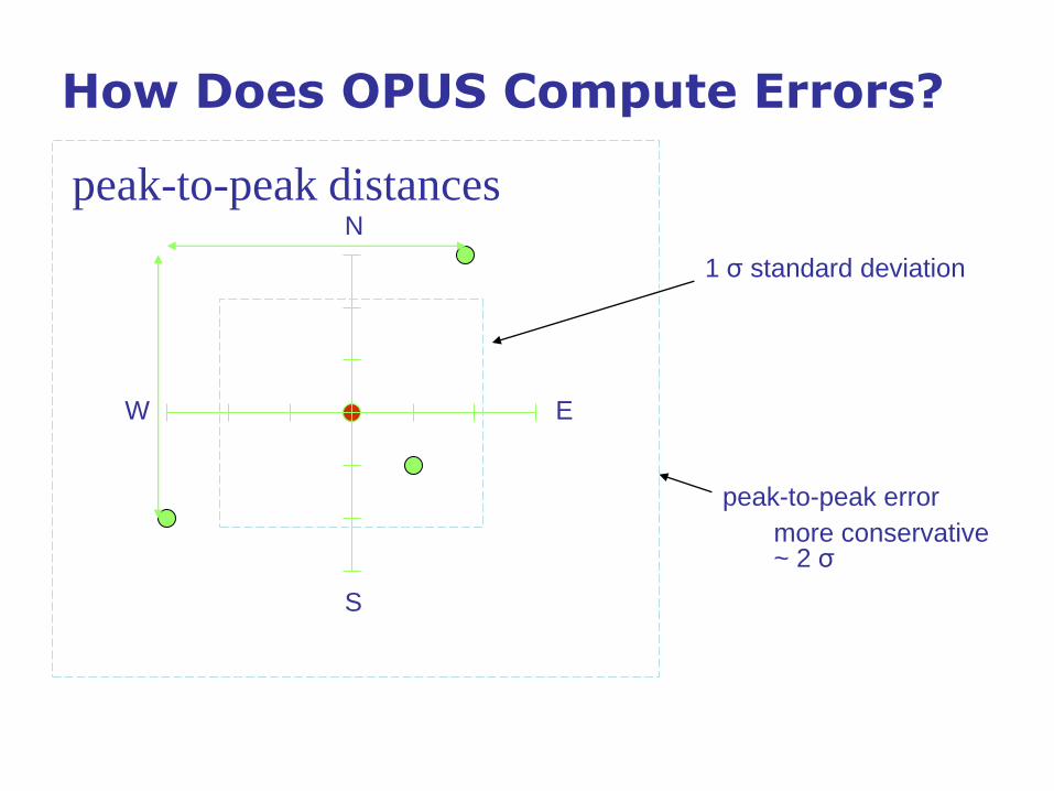
How Does OPUS Compute Errors?
EW
S
N
1 σ standard deviation
peak-to-peak error
more conservative~ 2 σ
peak-to-peak distances
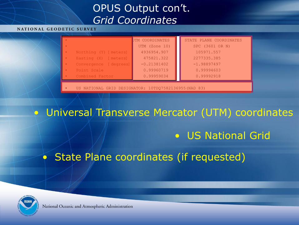
• UTM COORDINATES STATE PLANE COORDINATES
• UTM (Zone 10) SPC (3601 OR N)
• Northing (Y) [meters] 4936954.907 105971.557
• Easting (X) [meters] 475821.322 2277335.385
• Convergence [degrees] -0.21381402 -1.98897497
• Point Scale 0.99960719 0.99994603
• Combined Factor 0.99959034 0.99992918
• US NATIONAL GRID DESIGNATOR: 10TDQ7582136955(NAD 83)
• Universal Transverse Mercator (UTM) coordinates
• State Plane coordinates (if requested)
• US National Grid
OPUS Output con’t.Grid Coordinates
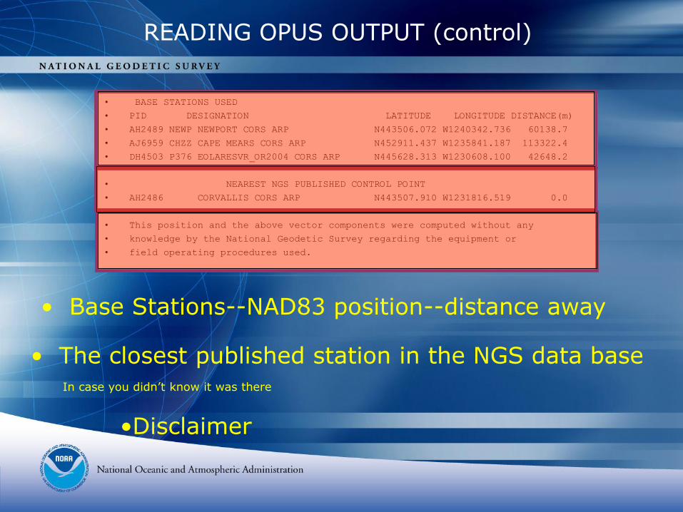
• BASE STATIONS USED
• PID DESIGNATION LATITUDE LONGITUDE DISTANCE(m)
• AH2489 NEWP NEWPORT CORS ARP N443506.072 W1240342.736 60138.7
• AJ6959 CHZZ CAPE MEARS CORS ARP N452911.437 W1235841.187 113322.4
• DH4503 P376 EOLARESVR_OR2004 CORS ARP N445628.313 W1230608.100 42648.2
• NEAREST NGS PUBLISHED CONTROL POINT
• AH2486 CORVALLIS CORS ARP N443507.910 W1231816.519 0.0
• This position and the above vector components were computed without any
• knowledge by the National Geodetic Survey regarding the equipment or
• field operating procedures used.
READING OPUS OUTPUT (control)
•Disclaimer
• Base Stations--NAD83 position--distance away
• The closest published station in the NGS data baseIn case you didn’t know it was there
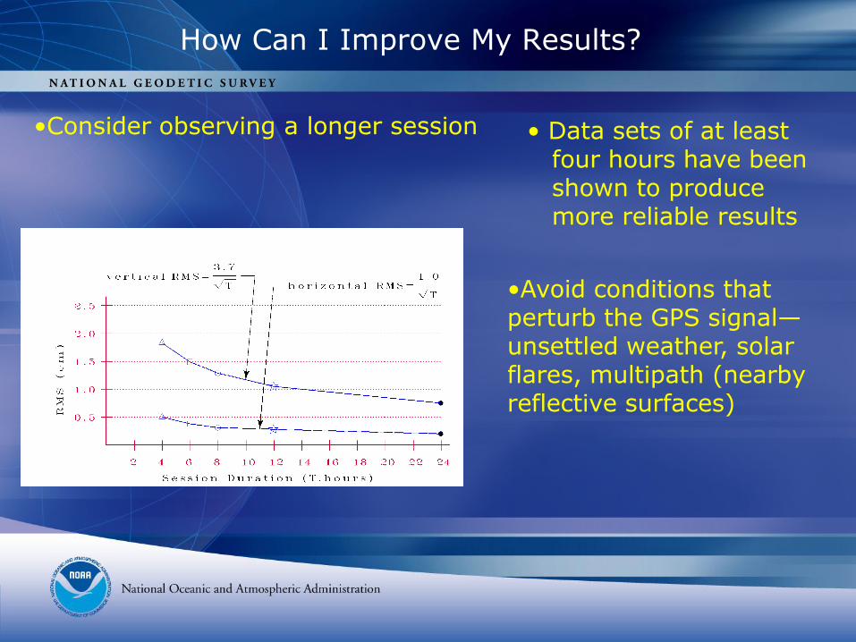
How Can I Improve My Results?
•Consider observing a longer session • Data sets of at leastfour hours have beenshown to producemore reliable results
•Avoid conditions that perturb the GPS signal—unsettled weather, solar flares, multipath (nearby reflective surfaces)
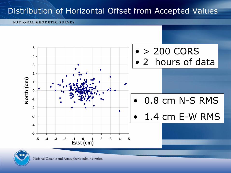
Distribution of Horizontal Offset from Accepted Values
-5
-4
-3
-2
-1
0
1
2
3
4
5
-5 -4 -3 -2 -1 0 1 2 3 4 5East (cm)
No
rth
(cm
)
• 0.8 cm N-S RMS
• 1.4 cm E-W RMS
• > 200 CORS • 2 hours of data
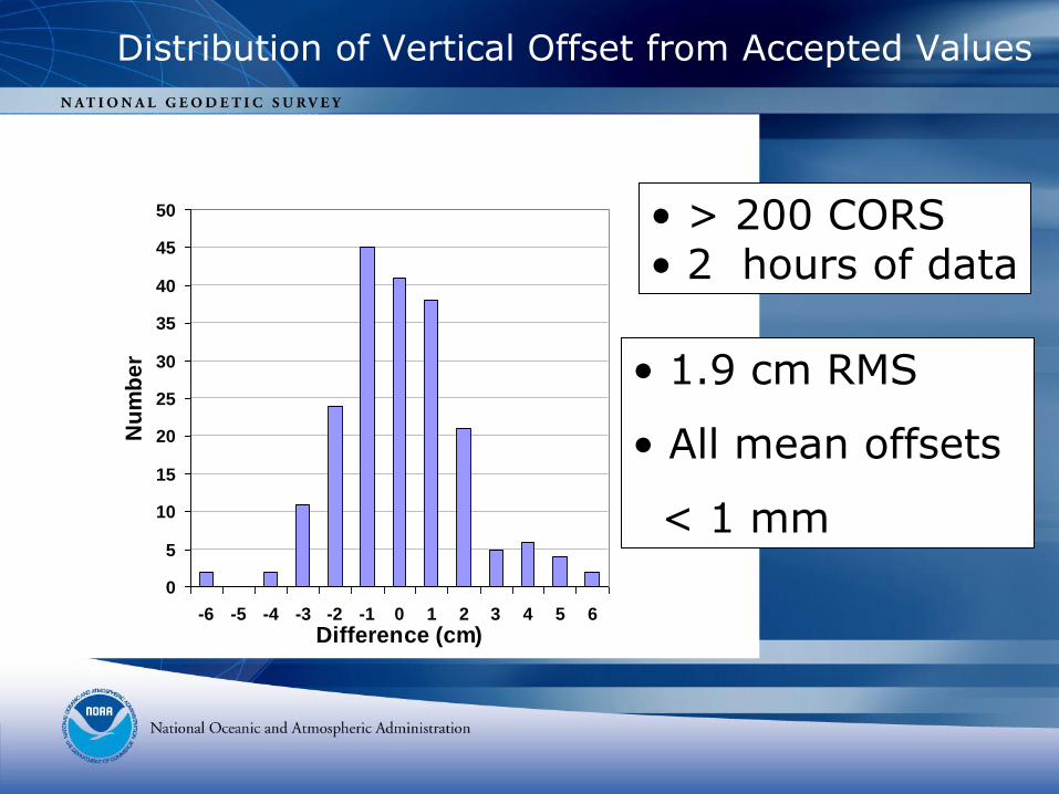
Distribution of Vertical Offset from Accepted Values
0
5
10
15
20
25
30
35
40
45
50
-6 -5 -4 -3 -2 -1 0 1 2 3 4 5 6
Difference (cm)
Nu
mb
er • 1.9 cm RMS
• All mean offsets
< 1 mm
• > 200 CORS• 2 hours of data
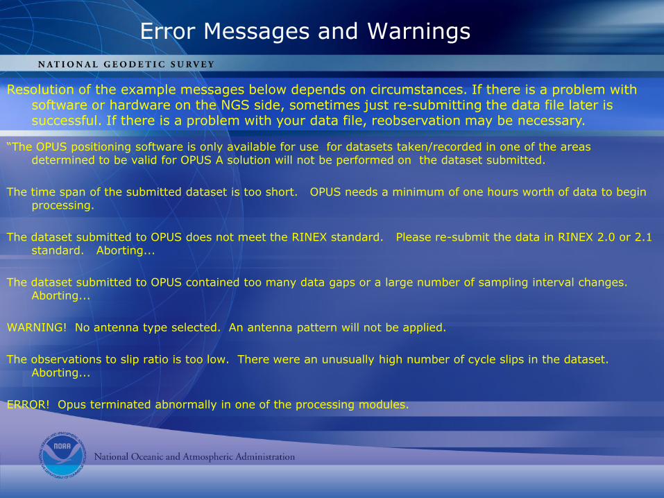
Error Messages and Warnings
Resolution of the example messages below depends on circumstances. If there is a problem with software or hardware on the NGS side, sometimes just re-submitting the data file later is successful. If there is a problem with your data file, reobservation may be necessary.
“The OPUS positioning software is only available for use for datasets taken/recorded in one of the areas determined to be valid for OPUS A solution will not be performed on the dataset submitted.
The time span of the submitted dataset is too short. OPUS needs a minimum of one hours worth of data to begin processing.
The dataset submitted to OPUS does not meet the RINEX standard. Please re-submit the data in RINEX 2.0 or 2.1 standard. Aborting...
The dataset submitted to OPUS contained too many data gaps or a large number of sampling interval changes. Aborting...
WARNING! No antenna type selected. An antenna pattern will not be applied.
The observations to slip ratio is too low. There were an unusually high number of cycle slips in the dataset. Aborting...
ERROR! Opus terminated abnormally in one of the processing modules.
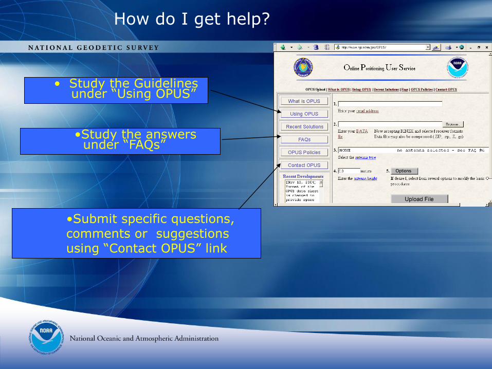
How do I get help?
• Study the Guidelines under “Using OPUS”
•Submit specific questions, comments or suggestions using “Contact OPUS” link
•Study the answersunder “FAQs”
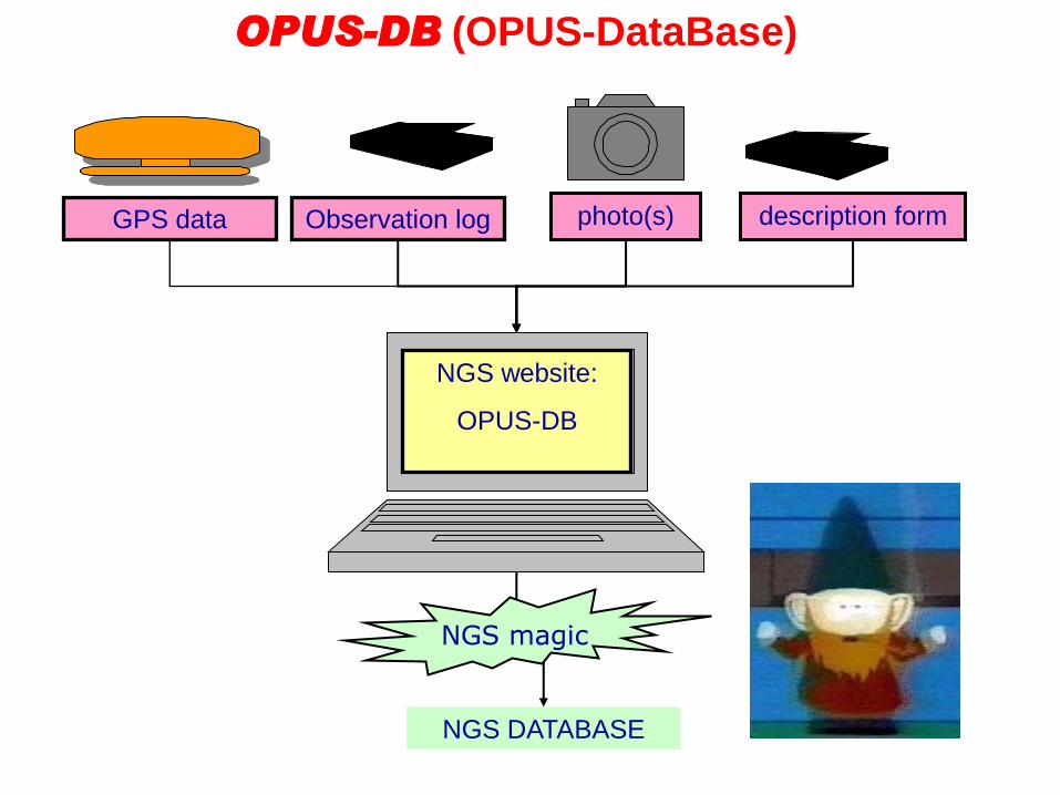
GPS data Observation log
OPUS-DB (OPUS-DataBase)
description formphoto(s)
NGS website:
OPUS-DB
NGS DATABASE
NGS magic
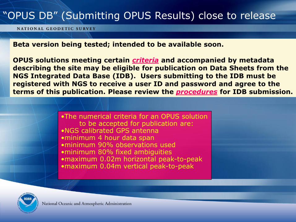
Beta version being tested; intended to be available soon.
OPUS solutions meeting certain criteria and accompanied by metadata describing the site may be eligible for publication on Data Sheets from the NGS Integrated Data Base (IDB). Users submitting to the IDB must be registered with NGS to receive a user ID and password and agree to the terms of this publication. Please review the procedures for IDB submission.
“OPUS DB” (Submitting OPUS Results) close to release
•The numerical criteria for an OPUS solutionto be accepted for publication are:
•NGS calibrated GPS antenna •minimum 4 hour data span •minimum 90% observations used •minimum 80% fixed ambiguities •maximum 0.02m horizontal peak-to-peak •maximum 0.04m vertical peak-to-peak

Demonstration
Application II

CONTROLLING A BRIDGE SURVEY
The accompanying slides were presented
at the
2002 CORS Forum
by
Gary Thompson
of the
North Carolina Geodetic Survey.
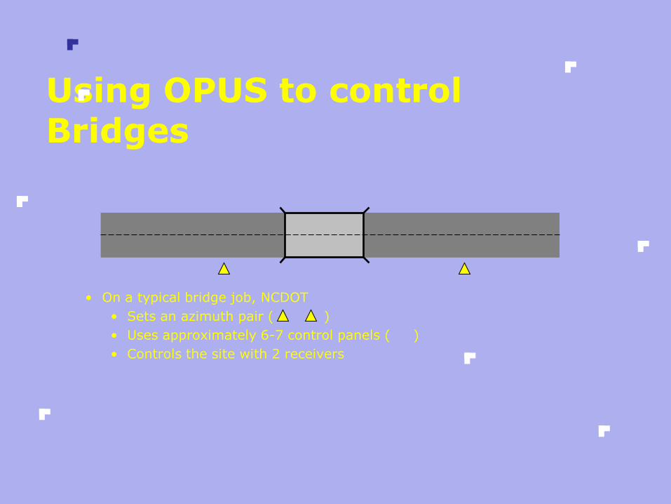
Using OPUS to control Bridges
• On a typical bridge job, NCDOT
• Sets an azimuth pair ( )
• Uses approximately 6-7 control panels ( )
• Controls the site with 2 receivers
P1
P2
P3
P4
P5
P6
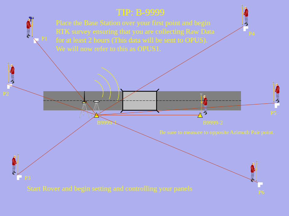
TIP: B-9999
B9999-1 B9999-2
Place the Base Station over your first point and begin
RTK survey ensuring that you are collecting Raw Data
for at least 2 hours (This data will be sent to OPUS).
We will now refer to this as OPUS1.
Start Rover and begin setting and controlling your panels
Be sure to measure to opposite Azimuth Pair point.
B9999-1 B9999-2
P1
P2
P3
P4
P5
P6
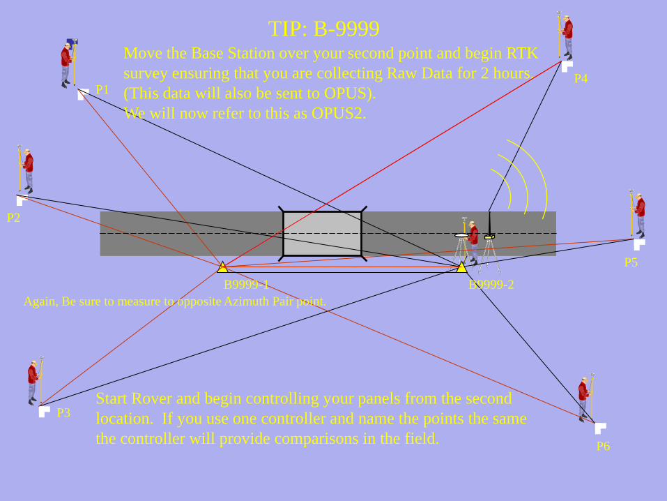
TIP: B-9999
Again, Be sure to measure to opposite Azimuth Pair point.
Move the Base Station over your second point and begin RTK
survey ensuring that you are collecting Raw Data for 2 hours.
(This data will also be sent to OPUS).
We will now refer to this as OPUS2.
Start Rover and begin controlling your panels from the second
location. If you use one controller and name the points the same
the controller will provide comparisons in the field.

Field Work is now complete.
The following steps need to be taken to finish the process:
Office Process
• Download the Raw Data and RTK dc files
• Convert both blocks of raw data to RINEX format using Trimble’s utility
• Upload the files to: http://www.ngs.noaa.gov/OPUS/
• Receive the results from OPUS via email in minutes
Continued...
• Import the dc file into Trimble Geomatics Office
• Update the initial base position for the first base to the coordinates provided by OPUS1
• After a recompute, everything in the dc file should be corrected relative to the first base location (OPUS1)
Continued ...
• The position for OPUS2 is only used for comparison to what was derived from OPUS1
• Coordinates can now be utilized as needed
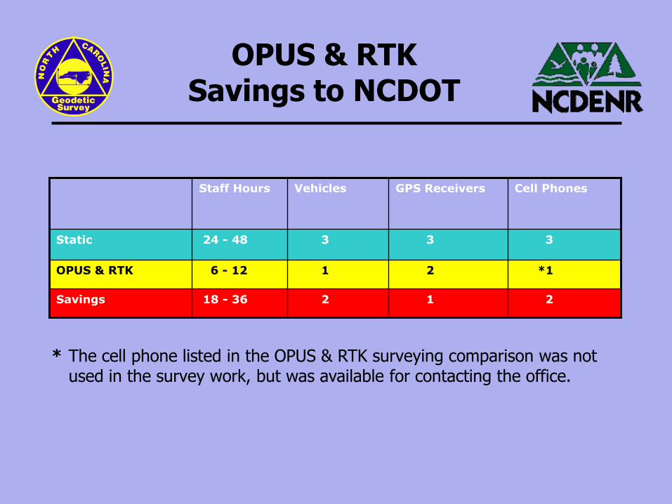
OPUS & RTK Savings to NCDOT
Cell PhonesGPS ReceiversVehiclesStaff Hours
2
1
3
18 - 36
6 - 12
24 - 48
Savings
OPUS & RTK
Static 33
21
*12
* The cell phone listed in the OPUS & RTK surveying comparison was not used in the survey work, but was available for contacting the office.
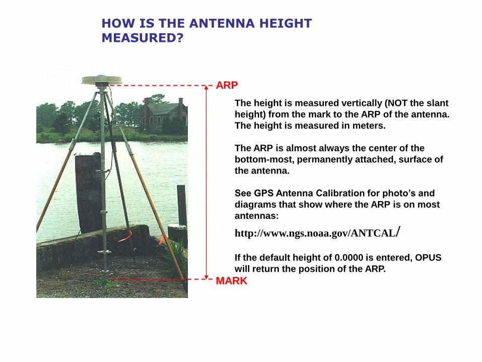
HOW IS THE ANTENNA HEIGHT MEASURED?
ARP
MARK
The height is measured vertically (NOT the slant
height) from the mark to the ARP of the antenna.
The height is measured in meters.
The ARP is almost always the center of the
bottom-most, permanently attached, surface of
the antenna.
See GPS Antenna Calibration for photo’s and
diagrams that show where the ARP is on most
antennas:
http://www.ngs.noaa.gov/ANTCAL/
If the default height of 0.0000 is entered, OPUS
will return the position of the ARP.
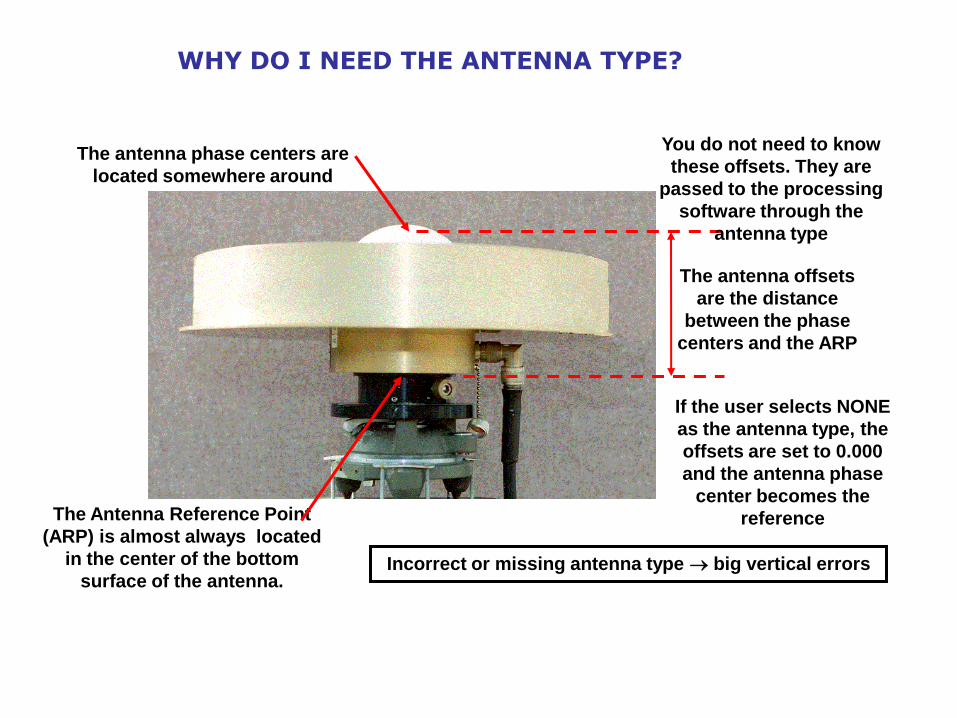
WHY DO I NEED THE ANTENNA TYPE?
The antenna phase centers are
located somewhere around
here.
The Antenna Reference Point
(ARP) is almost always located
in the center of the bottom
surface of the antenna.
The antenna offsets
are the distance
between the phase
centers and the ARP
If the user selects NONE
as the antenna type, the
offsets are set to 0.000
and the antenna phase
center becomes the
reference
You do not need to know
these offsets. They are
passed to the processing
software through the
antenna type
Incorrect or missing antenna type big vertical errors
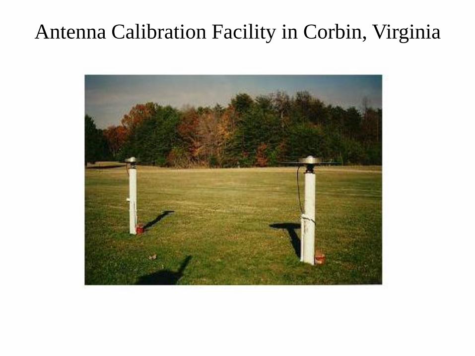
Antenna Calibration Facility in Corbin, Virginia
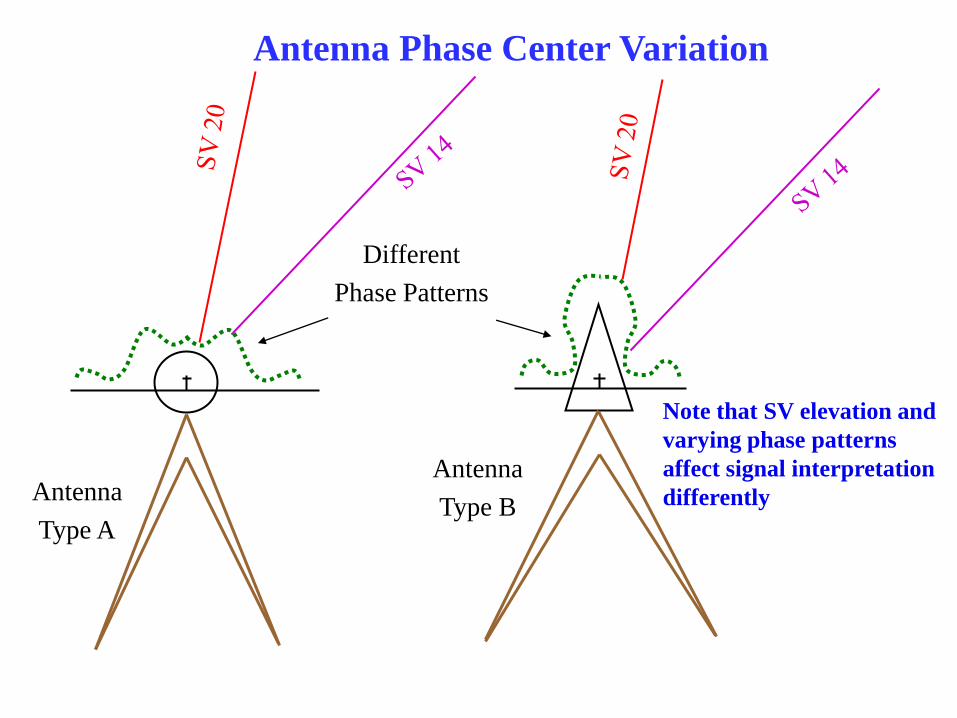
Note that SV elevation and
varying phase patterns
affect signal interpretation
differently
.
.
.
.
.
.
.
.
.
.
.
.
Antenna
Type A
Antenna
Type B
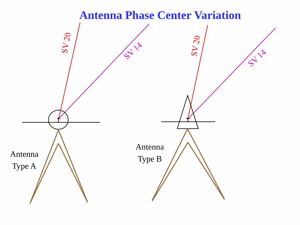
Antenna Phase Center Variation
.
.
.
.
.
.
.
.
.
.
.
.
Antenna
Type A
Antenna
Type B
Different
Phase Patterns
Note that SV elevation and
varying phase patterns
affect signal interpretation
differently
Antenna Phase Center Variation
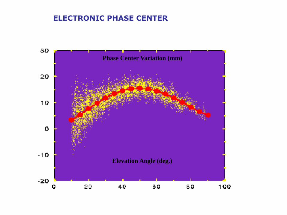
ELECTRONIC PHASE CENTER
Elevation Angle (deg.)
Phase Center Variation (mm)
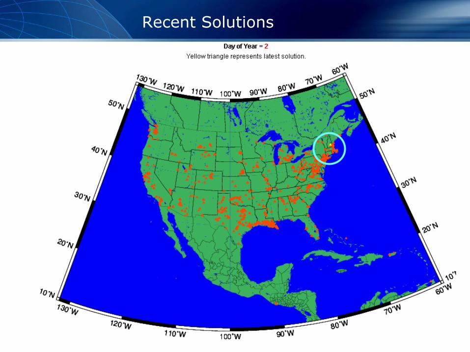
Recent Solutions
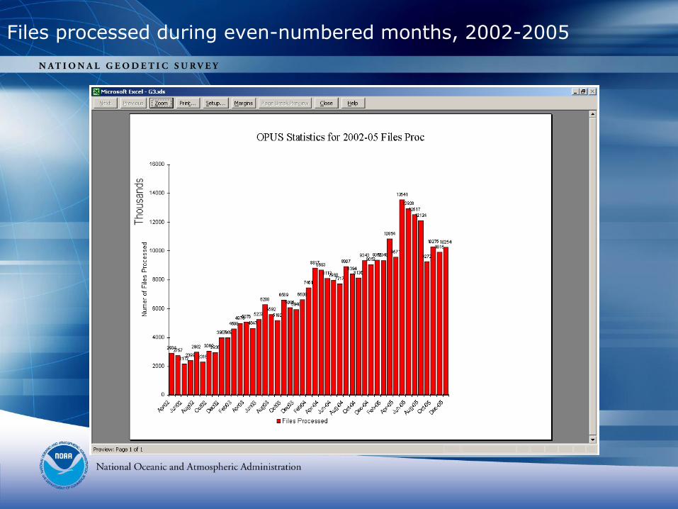
Files processed during even-numbered months, 2002-2005
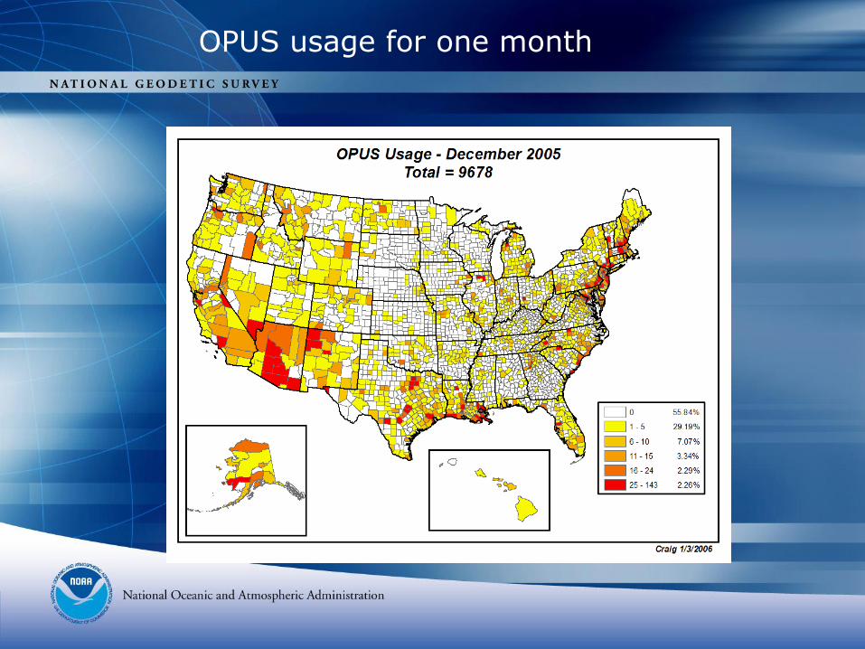
OPUS usage for one month
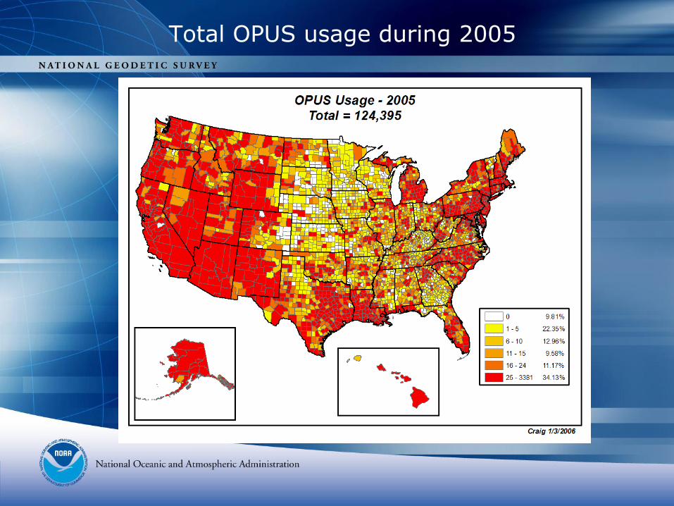
Total OPUS usage during 2005
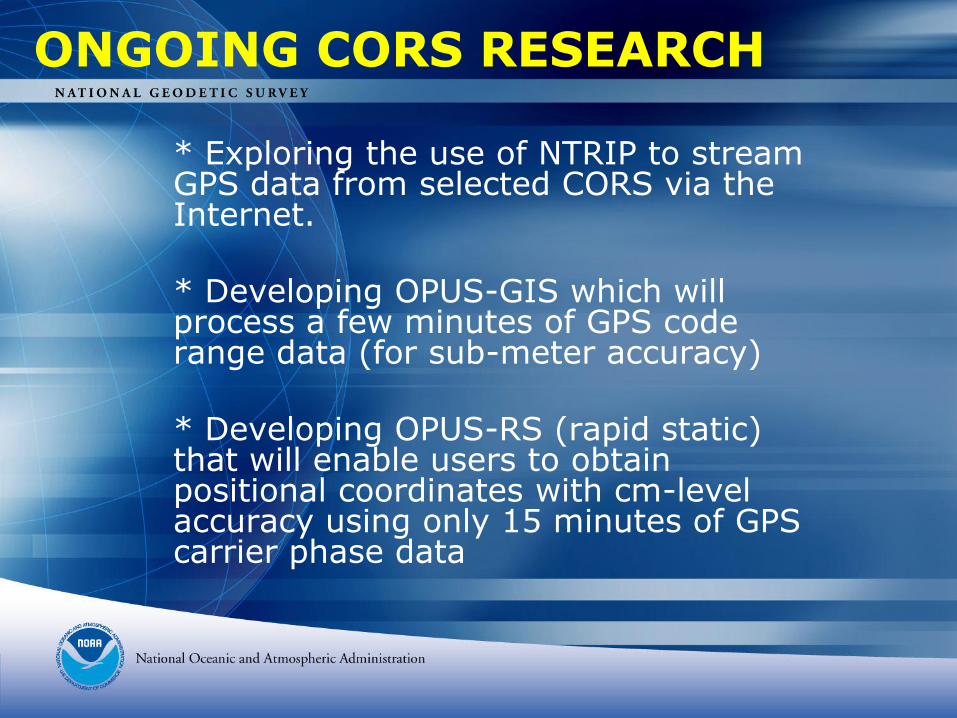
ONGOING CORS RESEARCH
* Exploring the use of NTRIP to stream GPS data from selected CORS via the Internet.
* Developing OPUS-GIS which will process a few minutes of GPS code range data (for sub-meter accuracy)
* Developing OPUS-RS (rapid static) that will enable users to obtain positional coordinates with cm-level accuracy using only 15 minutes of GPS carrier phase data
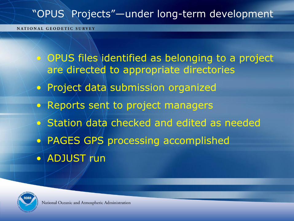
“OPUS Projects”—under long-term development
• OPUS files identified as belonging to a project are directed to appropriate directories
• Project data submission organized
• Reports sent to project managers
• Station data checked and edited as needed
• PAGES GPS processing accomplished
• ADJUST run