Embed Size (px)
Citation preview
Optotrak CertusTool Strober Guide
Revision 2October 2005
IMPORTANTPlease read this entire
document before usingthe Tool Strober

Copyright 2005 Northern Digital Inc. All Rights Reserved.
p Printed in Canada.
Part number: IL-1070076
Revision Status
Revision Number Date Description2 05/10/05 ToolBench refences removed. General
update to new template.

Disclaimer of Warranties and Limitation of Liability
Published by: Northern Digital Inc.103 Randall Dr.Waterloo, Ontario, Canada N2V 1C5Telephone: +1 (519) 884-5142Toll Free: +1 (877) 634 634 0Global: ++ (800) 634 634 00Facsimile: +1 (519) 884-5184Website: www.ndigital.com
Copyright 2005, Northern Digital Inc.All rights reserved. No part of this document may be reproduced, transcribed, trans-mitted, distributed, modified, merged, translated into any language or used in any form by any means - graphic, electronic, or mechanical, including but not limited to photocopying, recording, taping or information storage and retrieval systems - without the prior written consent of Northern Digital Inc. Certain copying of the software included herein is unlawful. Refer to your software license agreement for information respecting permitted copying.
Disclaimer of Warranties and Limitation of Liabilities
Northern Digital Inc. has taken due care in preparing this document and the programs and data on the electronic media accompanying this document including research, development, and testing.This document describes the state of Northern Digital Inc.’s knowledge respecting the subject matter herein at the time of its publication, and may not reflect its state of knowledge at all times in the future. Northern Digital Inc. has carefully reviewed this document for technical accuracy. If errors are suspected, the user should consult with Northern Digital Inc. prior to proceeding. Northern Digital Inc. makes no expressed or implied warranty of any kind with regard to this document or the programs and data on the electronic media accompanying this document. Northern Digital Inc. makes no representation, condition or warranty to the user or any other party with respect to the adequacy of this document for any particular pur-pose or with respect to its adequacy to produce a particular result. The user’s right to recover damages caused by fault or negligence on the part of Northern Digital Inc. shall be limited to the amount paid by the user to Northern Digital Inc. for the provi-sion of this document. In no event shall Northern Digital Inc. be liable for special, col-
Optotrak Certus Tool Strober Guide - Revision 2

lateral, incidental, direct, indirect or consequential damages, losses, costs, charges, claims, demands, or claim for lost profits, data, fees or expenses of any nature or kind.Product names listed are trademarks of their respective manufacturers. Company names listed are trademarks or trade names of their respective companies.
Optotrak Certus Tool Strober Guide - Revision 2
Table of Contents
Table of Contents
Read Me First! . . . . . . . . . . . . . . . . . . . . . . . . . . . . . . . . . . . . . . . . . . . . . . iii
Warnings . . . . . . . . . . . . . . . . . . . . . . . . . . . . . . . . . . . . . . . . . . . . . . . iiiCautions . . . . . . . . . . . . . . . . . . . . . . . . . . . . . . . . . . . . . . . . . . . . . . . . ivContact Information . . . . . . . . . . . . . . . . . . . . . . . . . . . . . . . . . . . . . . . ivUpdates. . . . . . . . . . . . . . . . . . . . . . . . . . . . . . . . . . . . . . . . . . . . . . . . . iv
1 Introduction . . . . . . . . . . . . . . . . . . . . . . . . . . . . . . . . . . . . . . . . . . . . . 1
1.1 Related Accessories . . . . . . . . . . . . . . . . . . . . . . . . . . . . . . . . . . . . 2
2 Strober Capabilities. . . . . . . . . . . . . . . . . . . . . . . . . . . . . . . . . . . . . . . 3
2.1 LED and Switch Support . . . . . . . . . . . . . . . . . . . . . . . . . . . . . . . . 3 2.2 Communications . . . . . . . . . . . . . . . . . . . . . . . . . . . . . . . . . . . . . . 3 2.3 Compatibility . . . . . . . . . . . . . . . . . . . . . . . . . . . . . . . . . . . . . . . . . 3 2.4 Convenience. . . . . . . . . . . . . . . . . . . . . . . . . . . . . . . . . . . . . . . . . . 4 2.5 Software Configuration . . . . . . . . . . . . . . . . . . . . . . . . . . . . . . . . . 4
3 Connecting the Strober and Tools. . . . . . . . . . . . . . . . . . . . . . . . . . . 5
3.1 Connecting the Strober to the System Control Unit . . . . . . . . . . . 5 3.2 Strober Port Connections . . . . . . . . . . . . . . . . . . . . . . . . . . . . . . . . 6 3.3 Strober Status LED . . . . . . . . . . . . . . . . . . . . . . . . . . . . . . . . . . . . 6 3.4 Tool Port Connections . . . . . . . . . . . . . . . . . . . . . . . . . . . . . . . . . . 7 3.5 Strober Activation Order . . . . . . . . . . . . . . . . . . . . . . . . . . . . . . . . 7 3.6 Strober Extension Cable. . . . . . . . . . . . . . . . . . . . . . . . . . . . . . . . . 8 3.7 Connecting Tools to the Strober . . . . . . . . . . . . . . . . . . . . . . . . . . 9
4 Using the Swivel Clip . . . . . . . . . . . . . . . . . . . . . . . . . . . . . . . . . . . . 10
4.1 Fastening the Tab to the Strober . . . . . . . . . . . . . . . . . . . . . . . . . 11
Optotrak Certus Tool Strober Guide - Revision 2 i
Table of Contents
4.2 Clip Orientation . . . . . . . . . . . . . . . . . . . . . . . . . . . . . . . . . . . . . .11 4.3 Removing the Strober from the Swivel Clip . . . . . . . . . . . . . . . .12
5 Wiring Switches . . . . . . . . . . . . . . . . . . . . . . . . . . . . . . . . . . . . . . . . .13
6 Abbreviations and Acronyms . . . . . . . . . . . . . . . . . . . . . . . . . . . . . .15
7 Troubleshooting. . . . . . . . . . . . . . . . . . . . . . . . . . . . . . . . . . . . . . . . .16
8 Equipment Symbols. . . . . . . . . . . . . . . . . . . . . . . . . . . . . . . . . . . . . .18
ii Optotrak Certus Tool Strober Guide - Revision 2
Read Me First!
Read Me First!Read this section before continuing with the rest of the guide.
Warnings
In all NDI documentation, warnings are marked by this symbol. Follow the information in the accompanying paragraph to avoid personal injury.
1. An e-type strober must be connected to an e-type port on the e-type System Control Unit to maintain Type BF isolation. Check that the colours of both connectors match. The keying for the different types of connectors is unique to prevent using an s-type strober in an e-type port.
2. To maintain type BF isolation, all components between the e-type ports on an e-type System Control Unit and the patient must meet or exceed the certifications and approvals of the Optotrak Certus System. Serious personal injury could result if the appropriate type of isolation is not maintained.
3. Ensure that the correct rigid body file is used with the corresponding rigid body. If the rigid body definition does not match the rigid body, the rigid body may still be tracked but will report incorrect data. If a rigid body definition contains imaginary markers, but is used with the incorrect rigid body, the rigid body may still be tracked, but will report incorrect data for the imaginary points. Incorrect data could cause personal injury and/or property damage.
Warning!
Optotrak Certus Tool Strober Guide - Revision 2 iii

Read Me First!
Cautions
Caution! In all NDI documentation, cautions are marked with the word "Caution!". Follow the information in the accompanying paragraph to avoid damage to equipment.
1. For cautions specific to the devices in your measurement system please refer to all the manuals accompanying your system.
Contact InformationIf you have any questions regarding the content of this guide or the operation of this product, please contact us:
UpdatesNDI is committed to continuous improvements in the quality and versatility of its software and hardware. To obtain the best results with your NDI system, check the NDI Support Site regularly for update information:
http://support.ndigital.com
iv Optotrak Certus Tool Strober Guide - Revision 2
Introduction
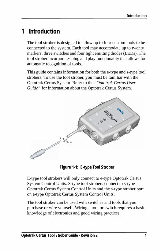
1 IntroductionThe tool strober is designed to allow up to four custom tools to be connected to the system. Each tool may accomodate up to twenty markers, three switches and four light emitting diodes (LEDs). The tool strober incorporates plug and play functionality that allows for automatic recognition of tools.
This guide contains information for both the e-type and s-type tool strobers. To use the tool strober, you must be familiar with the Optotrak Certus System. Refer to the “Optotrak Certus User Guide” for information about the Optotrak Certus System.
Figure 1-1: E-type Tool Strober
E-type tool strobers will only connect to e-type Optotrak Certus System Control Units. S-type tool strobers connect to s-type Optotrak Certus System Control Units and the s-type strober port on e-type Optotrak Certus System Control Units.
The tool strober can be used with switches and tools that you purchase or wire yourself. Wiring a tool or switch requires a basic knowledge of electronics and good wiring practices.
Optotrak Certus Tool Strober Guide - Revision 2 1
Introduction
This guide includes information on:
• strober capabilities
• connecting the strober to the System Control Unit
• connecting tools to the strober
• using the swivel clip
• wiring switches
• troubleshooting
• available parts
1.1 Related AccessoriesOther strobers that are available for the Optotrak Certus System include:
• axon strober, which has a DB25 connector that can be used for either markers, rigid bodies or a tool.
• marker strober, which can activate up to 24 markers attached to RJH connectors.
• 3020 strober adapter, which allows Optotrak 3020 strobers to be used with the Optotrak Certus System.
2 Optotrak Certus Tool Strober Guide - Revision 2
Strober Capabilities
2 Strober CapabilitiesThe tool strober is designed to allow up to four custom tools to be connected to the system. Each tool may accomodate up to twenty markers, three switches and four LEDs. The tool strober is also compatible with Polaris tools, that incorporate metallic markers.
Three strobers (marker, axon and tool), the strober extension cable, and the System Control Unit are available in both s-type and e-type. The e-type components are intended for applications that require type BF isolation. The e-type System Control Unit includes two e-type strober ports and a single s-type strober port. All of the strober ports on the s-type System Control Unit are s-type.
2.1 LED and Switch SupportThe tool strober has a visible strober status LED, four tool port LEDs, and two optional, external switches connected directly to the strober through a 2.5 mm headphone jack connection. The external switches are intended for feedback from the user to the application software. The signal returned from these switches is not fast enough to be considered real time, and cannot be used to synchronize the Optotrak Certus System with external devices.
2.2 CommunicationsThe strober receives marker activation information from the Optotrak Certus System and sends tool and status information back to the system. The strober powers the markers in the order specified by software running on the host computer.
2.3 CompatibilityTool strobers can be used simultaneously with other strobers, as well as the 3020 strober adapter. Strober types can be mixed within a daisy chain; 3020 strober adapters must always be located at the end of the chain.
Optotrak Certus Tool Strober Guide - Revision 2 3
Strober Capabilities
2.4 ConvenienceA swivel clip, which allows the strober to be attached to objects and rotate, is included with the strober. This facilitates fastening the strober to the subject.
2.5 Software ConfigurationUsing either application software or the routines described in the device handle section of the Application Programmers’ Interface, you can set the:
• name of the strober
• number of markers to be activated
• order in which markers will be activated
• behaviour of the system in response to a change in the status of the switches
• behaviour of visible LEDs on tools
• information about a rigid body that includes the marker(s) being controlled by the strober
• marker power
4 Optotrak Certus Tool Strober Guide - Revision 2
Connecting the Strober and Tools
3 Connecting the Strober and Tools
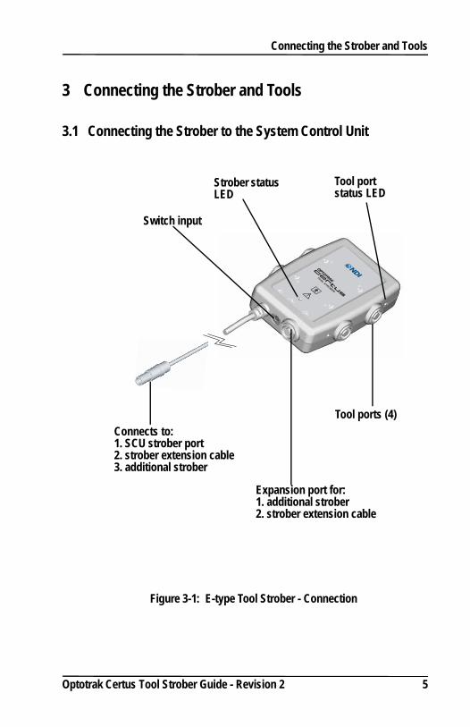
3.1 Connecting the Strober to the System Control Unit
Figure 3-1: E-type Tool Strober - Connection
Connects to:1. SCU strober port2. strober extension cable3. additional strober
Expansion port for:1. additional strober2. strober extension cable
Switch input
Strober status LED
Tool ports (4)
Tool port status LED
Optotrak Certus Tool Strober Guide - Revision 2 5
Connecting the Strober and Tools
3.2 Strober Port ConnectionsStrobers designed for s-type applications have connectors equipped with a blue nut on both the strober port connector and the expansion port. They will connect to a port that is also equipped with a blue nut.
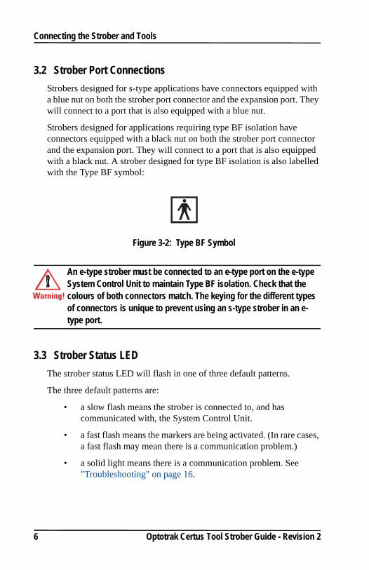
Strobers designed for applications requiring type BF isolation have connectors equipped with a black nut on both the strober port connector and the expansion port. They will connect to a port that is also equipped with a black nut. A strober designed for type BF isolation is also labelled with the Type BF symbol:
Figure 3-2: Type BF Symbol
An e-type strober must be connected to an e-type port on the e-type System Control Unit to maintain Type BF isolation. Check that the colours of both connectors match. The keying for the different types of connectors is unique to prevent using an s-type strober in an e-type port.
3.3 Strober Status LEDThe strober status LED will flash in one of three default patterns.
The three default patterns are:
• a slow flash means the strober is connected to, and has communicated with, the System Control Unit.
• a fast flash means the markers are being activated. (In rare cases, a fast flash may mean there is a communication problem.)
• a solid light means there is a communication problem. See "Troubleshooting" on page 16.
Warning!
6 Optotrak Certus Tool Strober Guide - Revision 2
Connecting the Strober and Tools
3.4 Tool Port ConnectionsWhen designing tools for applications that do not require type BF isolation, you should use entirely grey tool port connectors to signify the tool is s-type. An s-type tool port is keyed differently from an e-type tool port.
When designing tools for applications requiring type BF isolation, you should use entirely black tool port connectors to signify it is an e-type tool. An e-type tool port is keyed differently from an s-type tool port.
Note: More detailed technical descriptions of the Optotrak Certus System components are included in the “Optotrak Certus User Guide”.
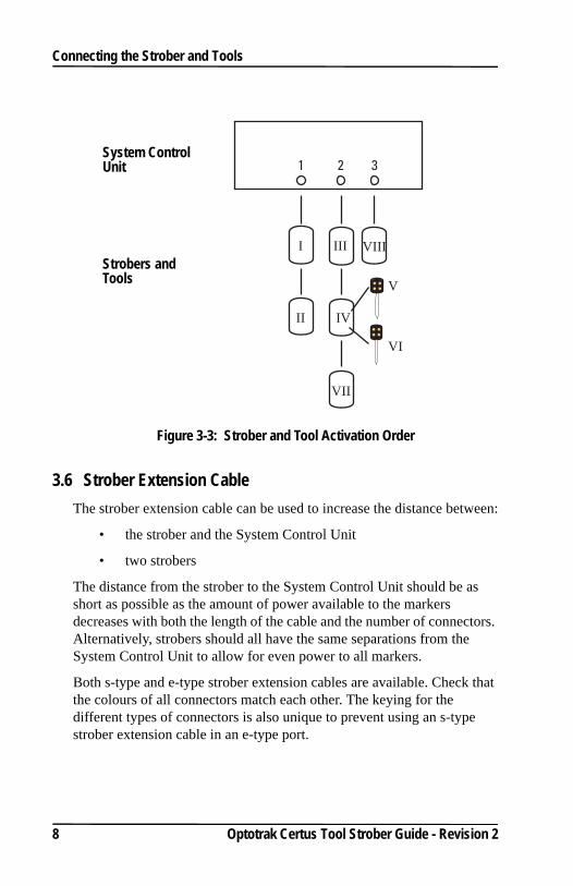
3.5 Strober Activation OrderThe order in which strobers and tools are activated is determined by the strober port to which they are connected. All the strobers which are connected to strober port 1 are activated before the strobers on port 2, which are activated before the strobers on port 3.
Tools and tool strobers are activated so that the tools connected to a tool strober are activated directly after the tool strober itself, and before the next strober in the chain. See Figure 3-3 on page 8, where the strobers and tools are numbered I to VIII.
Optotrak Certus Tool Strober Guide - Revision 2 7
Connecting the Strober and Tools
Figure 3-3: Strober and Tool Activation Order
3.6 Strober Extension CableThe strober extension cable can be used to increase the distance between:
• the strober and the System Control Unit
• two strobers
The distance from the strober to the System Control Unit should be as short as possible as the amount of power available to the markers decreases with both the length of the cable and the number of connectors. Alternatively, strobers should all have the same separations from the System Control Unit to allow for even power to all markers.
Both s-type and e-type strober extension cables are available. Check that the colours of all connectors match each other. The keying for the different types of connectors is also unique to prevent using an s-type strober extension cable in an e-type port.
1 2 3
I
II
III
IV
VI
V
VIII
VII
System Control Unit
Strobers and Tools
8 Optotrak Certus Tool Strober Guide - Revision 2
Connecting the Strober and Tools
To maintain type BF isolation, all components between the e-type ports on an e-type System Control Unit and the patient must meet or exceed the certifications and approvals of the Optotrak Certus System. Serious personal injury could result if the appropriate type of isolation is not maintained.
3.7 Connecting Tools to the StroberTools are connected to the strober through a 10 pin, circular plastic connector. The tool port number is shown beside each tool port.
Tools can be plugged into any tool port. For example, tools could be plugged into tool ports 1 and 3, leaving tool ports 2 and 4 unoccupied.
The tool port status LED is located beside the tool port connectors on the side of the tool strober. The status LED may be:
• off when there is no tool plugged in
• green to indicate that the system is ready to track tools
• yellow if the tool has been recognised as present, but has not yet been initialized
Ensure that the correct rigid body file is used with the corresponding rigid body. If the rigid body definition does not match the rigid body, the rigid body may still be tracked but will report incorrect data. If a rigid body definition contains imaginary markers, but is used with the incorrect rigid body, the rigid body may still be tracked, but will report incorrect data for the imaginary points. Incorrect data could cause personal injury and/or property damage.
To ensure maximum tool and connector life, make sure you hold the connectors and not the cables when connecting and disconnecting tools.
Warning!
Warning!
Optotrak Certus Tool Strober Guide - Revision 2 9
Using the Swivel Clip
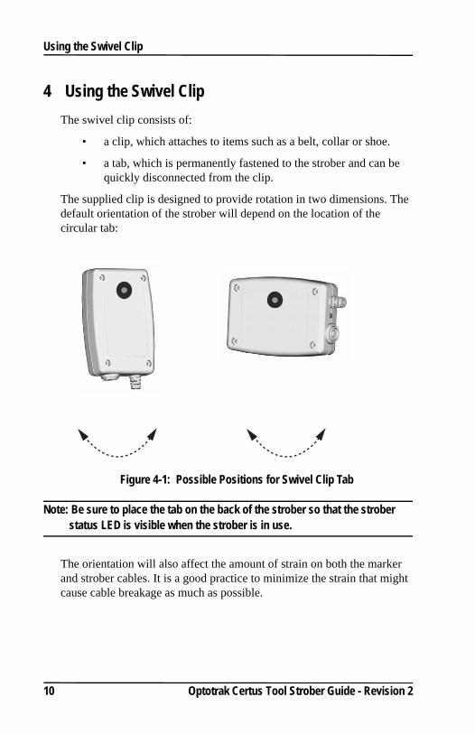
4 Using the Swivel ClipThe swivel clip consists of:
• a clip, which attaches to items such as a belt, collar or shoe.
• a tab, which is permanently fastened to the strober and can be quickly disconnected from the clip.
The supplied clip is designed to provide rotation in two dimensions. The default orientation of the strober will depend on the location of the circular tab:
Figure 4-1: Possible Positions for Swivel Clip Tab
Note: Be sure to place the tab on the back of the strober so that the strober status LED is visible when the strober is in use.
The orientation will also affect the amount of strain on both the marker and strober cables. It is a good practice to minimize the strain that might cause cable breakage as much as possible.
10 Optotrak Certus Tool Strober Guide - Revision 2
Using the Swivel Clip
4.1 Fastening the Tab to the Strober1. Clean both the back of the strober and the back of the tab with a
small amount of isopropyl alcohol (rubbing alcohol).
2. Remove the backing from one side of the adhesive strip and apply it to the tab.
3. Remove the backing from the other side of the adhesive strip and press the tab firmly onto the back of the strober in the preferred location.
4. If possible, do not use the tab for 24 hours to allow the adhesive to set firmly.
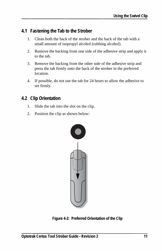
4.2 Clip Orientation 1. Slide the tab into the slot on the clip.
2. Position the clip as shown below:
Figure 4-2: Preferred Orientation of the Clip
Optotrak Certus Tool Strober Guide - Revision 2 11
Using the Swivel Clip
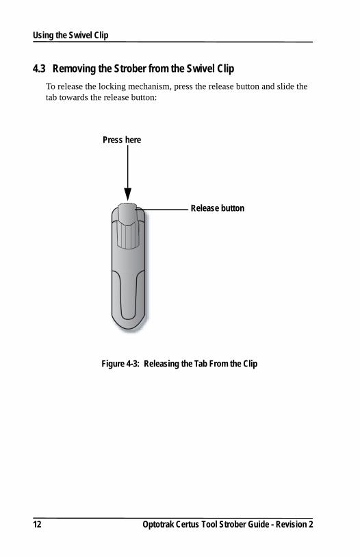
4.3 Removing the Strober from the Swivel ClipTo release the locking mechanism, press the release button and slide the tab towards the release button:
Figure 4-3: Releasing the Tab From the Clip
Press here
Release button
12 Optotrak Certus Tool Strober Guide - Revision 2
Wiring Switches
5 Wiring Switches
Note: If the tool strober will be used with NDI application software, it is important that the external switches have a “normally open” contact configuration.
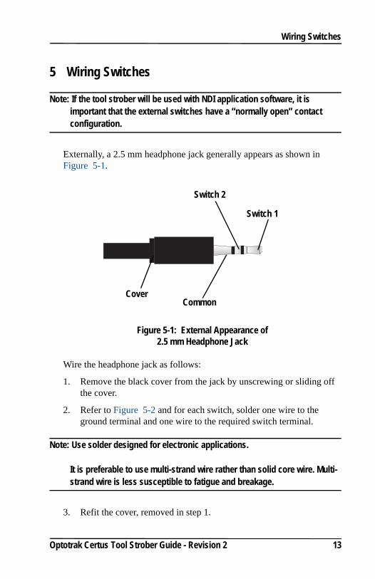
Externally, a 2.5 mm headphone jack generally appears as shown in Figure 5-1.
Figure 5-1: External Appearance of 2.5 mm Headphone Jack
Wire the headphone jack as follows:
1. Remove the black cover from the jack by unscrewing or sliding off the cover.
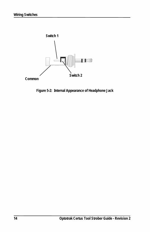
2. Refer to Figure 5-2 and for each switch, solder one wire to the ground terminal and one wire to the required switch terminal.
Note: Use solder designed for electronic applications.
It is preferable to use multi-strand wire rather than solid core wire. Multi-strand wire is less susceptible to fatigue and breakage.
3. Refit the cover, removed in step 1.
Common
Switch 1
Switch 2
Cover
Optotrak Certus Tool Strober Guide - Revision 2 13
Wiring Switches
Figure 5-2: Internal Appearance of Headphone Jack
CommonSwitch 2
Switch 1
14 Optotrak Certus Tool Strober Guide - Revision 2
Abbreviations and Acronyms
Optotrak Certus Tool Strober Guide - Revision 2 15
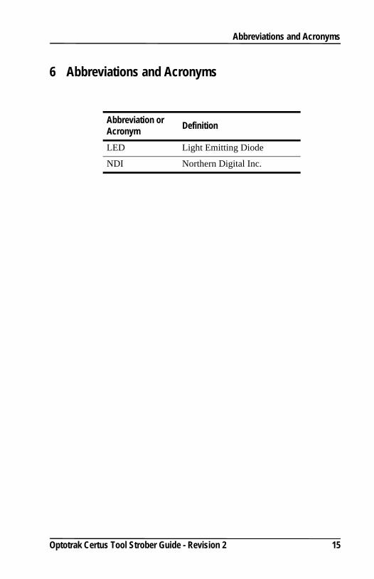
6 Abbreviations and Acronyms
Abbreviation or Acronym Definition
LED Light Emitting Diode
NDI Northern Digital Inc.
Troubleshooting
7 Troubleshooting
The strober connector won’t fit into the strober port connector on the System Control Unit.
You may be trying to connect an s-type connector into an e-type connector, or vice-versa. Check that the colour of the connectors match.
You may be trying to plug a tool connector in a strober port, or vice versa. Strober connectors have seven pins, while tool connectors have ten. S-type tool connectors are entirely grey, while e-type tool connectors are entirely black. Strober connectors are bi-coloured, with a grey end and a coloured nut.
When the strober is plugged into the System Control Unit, the strober status LED is off, a solid green or flashing quickly.
The strober connector may not be firmly seated in the receptacle. Check that all connectors are firmly connected. There is an audible ‘click’ when a connector is correctly seated.
Either the strober or the strober extension cable (if used) is faulty. To determine if either of these possibilities is the source:
a) Connect another strober to the extension cable. If the second strober works, there is a problem with the first strober.
b) Connect the strober without the extension cable. If the strober operates correctly, there is a problem with the extension cable.
Markers are missing.
The tool connector may not be firmly seated in the tool port. Check that all connectors are firmly connected. There is an audible ‘click’ when a connector is correctly seated.
Use the IR detection strip to determine if the marker is activated.
Ensure that the marker is directly facing the Position Sensor and is located in the measurement volume.
Some markers at the start of a frame may go missing at some combinations of high frame and marker frequencies. This can be resolved by decreasing either the frame or marker frequency.
16 Optotrak Certus Tool Strober Guide - Revision 2
Troubleshooting
The tool is not recognized.
The tool will not be recognized if the SROM device and FET were not included in the tool or if either of these devices is broken.
Ensure the tool does include both an SROM device and a FET and repair if necessary.
Optotrak Certus Tool Strober Guide - Revision 2 17
Equipment Symbols
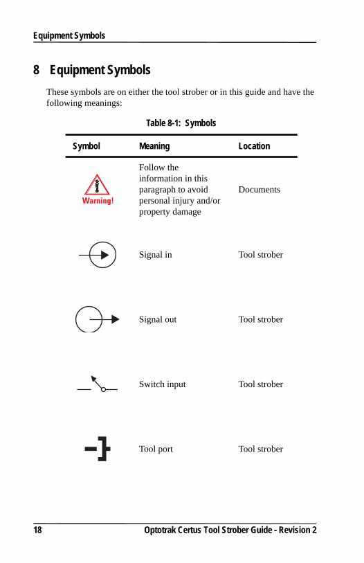
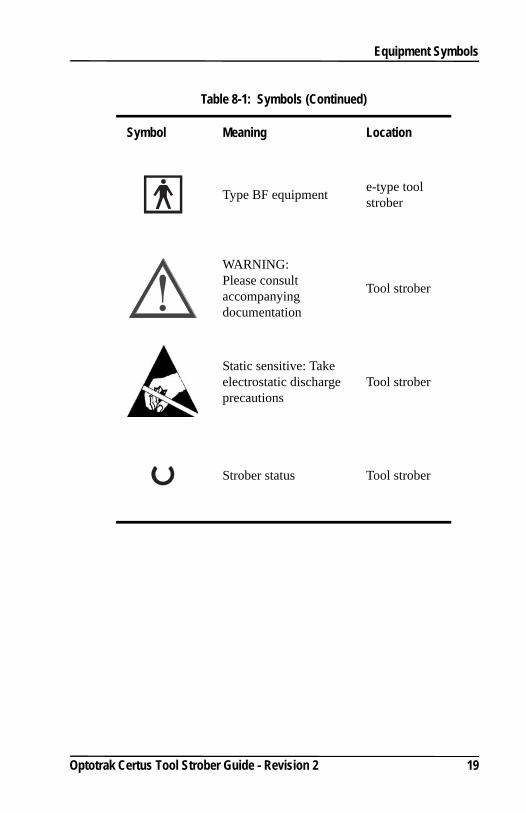
8 Equipment SymbolsThese symbols are on either the tool strober or in this guide and have the following meanings:
Table 8-1: Symbols
Symbol Meaning Location
Follow the information in this paragraph to avoid personal injury and/or property damage
Documents
Signal in Tool strober
Signal out Tool strober
Switch input Tool strober
Tool port Tool strober
Warning!
18 Optotrak Certus Tool Strober Guide - Revision 2
Equipment Symbols
Type BF equipment e-type tool strober
WARNING: Please consult accompanying documentation
Tool strober
Static sensitive: Take electrostatic discharge precautions
Tool strober
Strober status Tool strober
Table 8-1: Symbols (Continued)
Symbol Meaning Location
Optotrak Certus Tool Strober Guide - Revision 2 19
Index
Index
Numerics3020 strober adapter 3
Aabbreviations 15accessories 2acronyms 15Application Programmers’ Interface
4attachement clip 4
BBF isolation 6
Cclip 4communications 3compatibility 3configuration
software 4connecting the strober 5connection 5
Eequipment symbols 18expansion port 5
Hheadphone jack
appearance 13
Iintroduction 1
LLED 1LED and switch support 3light emitting diode 1
Mmarker activation
number of 4order of 4
marker power 4markers
number to activate 4
Optotrak Certus Tool Strober Guide - Revision 2 20
Index
Rrigid body
configuring 4
Ssoftware Configuration 4strober activation order 7strober capabilities 2, 3strober connection 5strober extension cable 8strober name 4strober status LED 5switch input 5switch support 3switches
setting number and behaviour 4
swivel clip 4, 10fastening the tab 11orientation 11removing the strober 12
symbols 18
Ttool activation order 8tool port connection 7tool port status LED 5tool ports 5type BF isolation iii, 6, 9
Wwiring tools and switches 12, 13
Optotrak Certus Tool Strober Guide - Revision 2 21