Embed Size (px)
Citation preview
Certification of Hazard Assessment 1
STANDARD OPERATING PROCEDURE
OPTOMEC AJP
College/Dept: Engineering Building/Room: Eng106
Laboratory Name: Idaho Microfabrication Lab Revision: 1.0
Principal Investigator: Pete Miranda Author: Travis G
Before the worked detailed in this procedure may begin, the intended user must read and understand this document.
This document must be approved by the PI, the college’s safety liaison, and EHSS.
Any changes to this document, however minor, must be submitted for approval by the PI, the college’s safety liaison, and EHSS.
Approval
Intended User:
Optomec AJP Operators See certified users list
Name, Title Signature Date
Name, Title Signature Date
Reviewed and Approved by:
Chris Siepert, Lab Safety Specialist
2-20-2018
Name, Title Signature Date
Pete Miranda, IML Director
2/20/18
Name, Title Signature Date
Overview
Setup and initialization of Optomec Aerosol Jet Printer
Scope
This SOP is intended to be a quick reference guide for assembly and setup of the Aerosol Jet Printer. More detailed instructions can be found in the Optomec AJ 200 Users Guide.
Potential Hazards
☒ Chemical ☒ Thermal ☐ Hydraulic ☐ Electrical ☐ Slip/Trip ☐ Biological
☒ Mechanical ☐ Radiation ☒ Pneumatic ☐ Fire ☐ Fall ☐ Other
Hazard Specifics: X, Y, Z, movement of stage/print head. Stage heater. Pressurized lines with ink materials. Machine lid
OPTOMEC AJP
2
Engineering Controls (EC)
☐ Fume hood ☐ Biosafety Cabinet ☒ Other Local Exhaust ☒ Shielding ☐ Other
EC Specifics: Machine shielding to prevent access during movement and pressurization
Training Requirements – except for classroom lab safety, must be completed prior to performing the procedure
☒ Classroom Laboratory Safety Awareness ☐ Radiation Worker
☐ Online Safety Topics (specify):
☐ Lab/Work Group Specific Training (specify):printable ink safety training
☒ Other (specify):waste management
Personal Protective Equipment (PPE)
☒ Safety glasses ☐ Safety goggles ☐ Face shield & safety glasses ☐ Face shield & safety goggles
☒ Lab coat ☐ Apron ☐ Tyvek suit ☐ Tyvek sleeves
☒ Gloves ☐ Leg coverings ☐ Hard hat ☐ Hearing protection
☐ Respirator ☐ Shoes ☐ Fall protection ☐ Other
PPE Description: Nitrile gloves, safety glasses, lab coats all provided in eng106
Equipment, Materials, Supplies, & Facility Requirements
Optomec AJP200, printable inks, lab wipes, Apiezon grease, compressed air, N2, chiller/H2O circulation system
Handling, Work Area & Storage Requirements
Clean workspace, ink cartridges are to be filled in an approved lab space hood, ink materials are to be stored in an approved lab storage space.
Emergency Response Equipment & Supplies
☒ Eyewash ☒ Fire extinguisher ☒ First aid kit ☐ Calcium gluconate gel (HF use)
☒ Safety shower ☐ Fire blanket ☒ Spill kit ☐ Emergency gas shutoffs
☐ Drench hose ☐ Other:
Description: Eyewash, safety shower, fire extinguisher, and first aid kit available in ENG106. Spill kit available in eng107.
Decontamination & Waste Disposal
Solvent trash available in eng106
Spill Response

OPTOMEC AJP
3
Follow IML SOP guidelines. Notify IML staff.
Additional Safety Information
Manufacturer Health and safety guidelines document available on printer PC.
References
Optomec AJP 200 Operators Manual
OPTOMEC AJP
4
Procedure
STEPS
Potential Hazards
EC, Haz. Mitigation Device, PPE
1.0 Print Head Assembly Pinch points Always wear gloves and safety glasses
1.1. Before using the AJP, you must first assemble the fine feature print head along with the chosen atomizer. There are two options for atomization:
1. Pneumatic 2. Ultrasonic
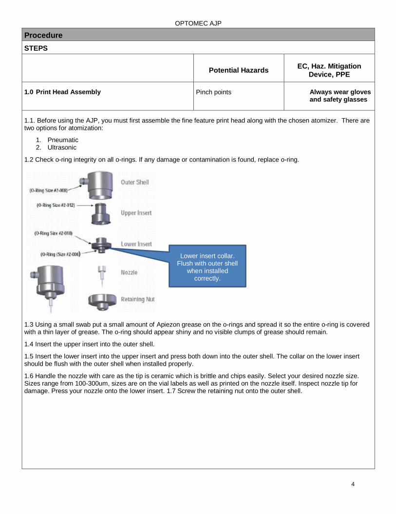
1.2 Check o-ring integrity on all o-rings. If any damage or contamination is found, replace o-ring.
1.3 Using a small swab put a small amount of Apiezon grease on the o-rings and spread it so the entire o-ring is covered with a thin layer of grease. The o-ring should appear shiny and no visible clumps of grease should remain.
1.4 Insert the upper insert into the outer shell.
1.5 Insert the lower insert into the upper insert and press both down into the outer shell. The collar on the lower insert should be flush with the outer shell when installed properly.
1.6 Handle the nozzle with care as the tip is ceramic which is brittle and chips easily. Select your desired nozzle size. Sizes range from 100-300um, sizes are on the vial labels as well as printed on the nozzle itself. Inspect nozzle tip for damage. Press your nozzle onto the lower insert. 1.7 Screw the retaining nut onto the outer shell.
Lower insert collar. Flush with outer shell
when installed correctly.
OPTOMEC AJP
5
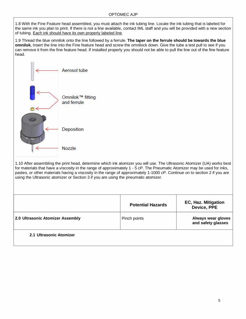
1.8 With the Fine Feature head assembled, you must attach the ink tubing line. Locate the ink tubing that is labeled for the same ink you plan to print. If there is not a line available, contact IML staff and you will be provided with a new section of tubing. Each ink should have its own properly labeled line.
1.9 Thread the blue omnilok onto the line followed by a ferrule. The taper on the ferrule should be towards the blue omnilok. Insert the line into the Fine feature head and screw the omnilock down. Give the tube a test pull to see if you can remove it from the fine feature head. If installed properly you should not be able to pull the line out of the fine feature head.
1.10 After assembling the print head, determine which ink atomizer you will use. The Ultrasonic Atomizer (UA) works best for materials that have a viscosity in the range of approximately 1 - 5 cP. The Pneumatic Atomizer may be used for inks, pastes, or other materials having a viscosity in the range of approximately 1-1000 cP. Continue on to section 2 if you are using the Ultrasonic atomizer or Section 3 if you are using the pneumatic atomizer.
Potential Hazards
EC, Haz. Mitigation Device, PPE
2.0 Ultrasonic Atomizer Assembly Pinch points Always wear gloves and safety glasses
2.1 Ultrasonic Atomizer
OPTOMEC AJP
6
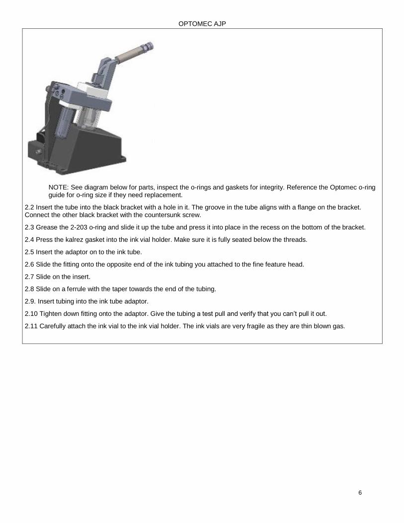
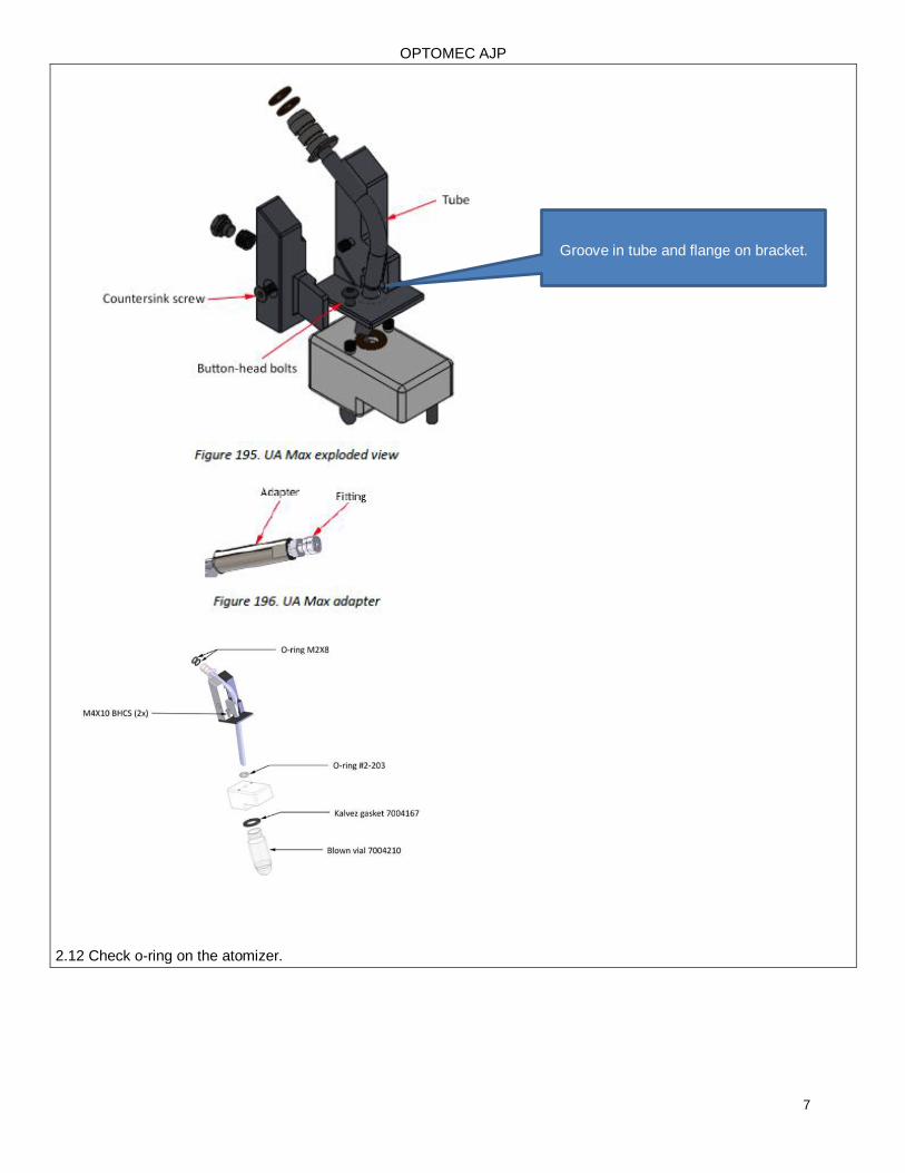
NOTE: See diagram below for parts, inspect the o-rings and gaskets for integrity. Reference the Optomec o-ring guide for o-ring size if they need replacement.
2.2 Insert the tube into the black bracket with a hole in it. The groove in the tube aligns with a flange on the bracket. Connect the other black bracket with the countersunk screw.
2.3 Grease the 2-203 o-ring and slide it up the tube and press it into place in the recess on the bottom of the bracket.
2.4 Press the kalrez gasket into the ink vial holder. Make sure it is fully seated below the threads.
2.5 Insert the adaptor on to the ink tube.
2.6 Slide the fitting onto the opposite end of the ink tubing you attached to the fine feature head.
2.7 Slide on the insert.
2.8 Slide on a ferrule with the taper towards the end of the tubing.
2.9. Insert tubing into the ink tube adaptor.
2.10 Tighten down fitting onto the adaptor. Give the tubing a test pull and verify that you can’t pull it out.
2.11 Carefully attach the ink vial to the ink vial holder. The ink vials are very fragile as they are thin blown gas.
OPTOMEC AJP
7
2.12 Check o-ring on the atomizer.
Groove in tube and flange on bracket.
OPTOMEC AJP
8
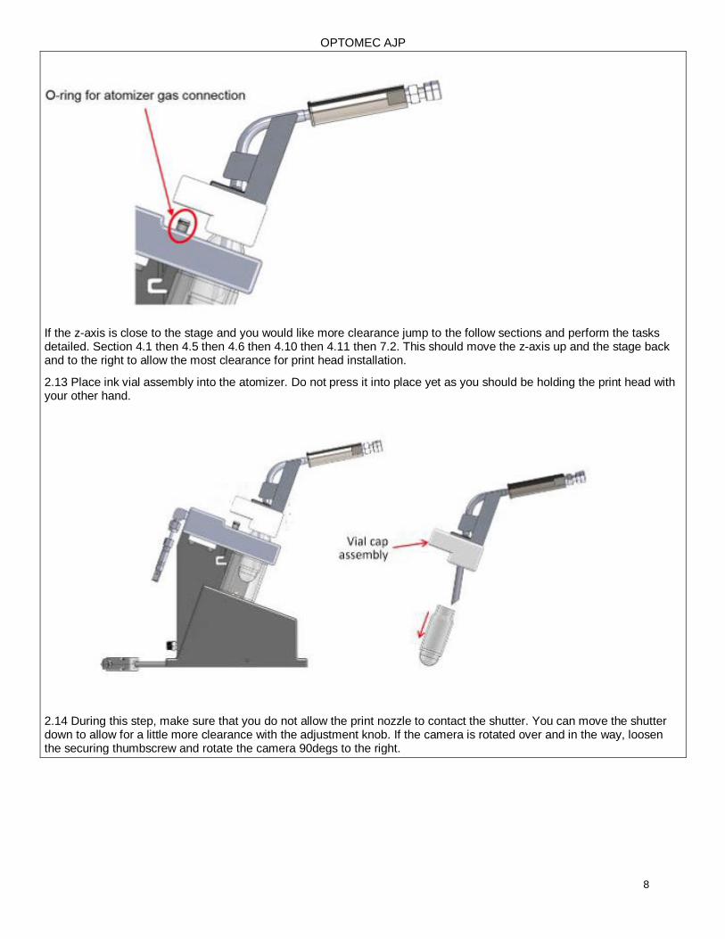
If the z-axis is close to the stage and you would like more clearance jump to the follow sections and perform the tasks detailed. Section 4.1 then 4.5 then 4.6 then 4.10 then 4.11 then 7.2. This should move the z-axis up and the stage back and to the right to allow the most clearance for print head installation.
2.13 Place ink vial assembly into the atomizer. Do not press it into place yet as you should be holding the print head with your other hand.
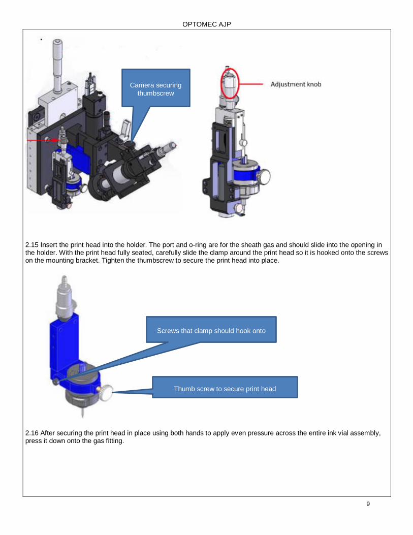
2.14 During this step, make sure that you do not allow the print nozzle to contact the shutter. You can move the shutter down to allow for a little more clearance with the adjustment knob. If the camera is rotated over and in the way, loosen the securing thumbscrew and rotate the camera 90degs to the right.
OPTOMEC AJP
9
2.15 Insert the print head into the holder. The port and o-ring are for the sheath gas and should slide into the opening in the holder. With the print head fully seated, carefully slide the clamp around the print head so it is hooked onto the screws on the mounting bracket. Tighten the thumbscrew to secure the print head into place.
2.16 After securing the print head in place using both hands to apply even pressure across the entire ink vial assembly, press it down onto the gas fitting.
Screws that clamp should hook onto
Thumb screw to secure print head
Camera securing
thumbscrew
OPTOMEC AJP
10
Potential Hazards
EC, Haz. Mitigation Device, PPE
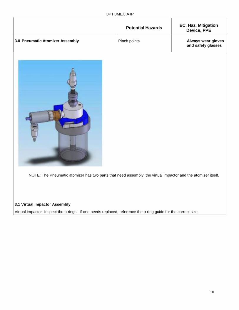
3.0 Pneumatic Atomizer Assembly Pinch points Always wear gloves and safety glasses
NOTE: The Pneumatic atomizer has two parts that need assembly, the virtual impactor and the atomizer itself.
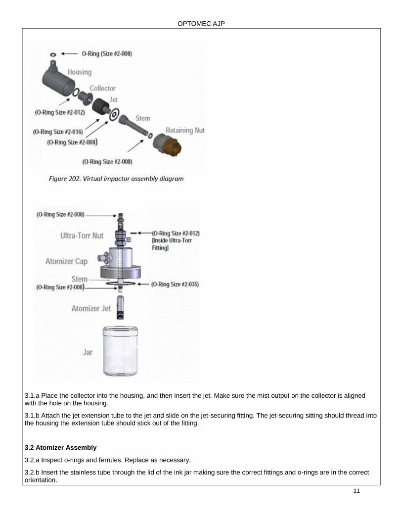
3.1 Virtual Impactor Assembly
Virtual impactor- Inspect the o-rings. If one needs replaced, reference the o-ring guide for the correct size.
OPTOMEC AJP
11
3.1.a Place the collector into the housing, and then insert the jet. Make sure the mist output on the collector is aligned with the hole on the housing.
3.1.b Attach the jet extension tube to the jet and slide on the jet-securing fitting. The jet-securing sitting should thread into the housing the extension tube should stick out of the fitting.
3.2 Atomizer Assembly
3.2.a Inspect o-rings and ferrules. Replace as necessary.
3.2.b Insert the stainless tube through the lid of the ink jar making sure the correct fittings and o-rings are in the correct orientation.
OPTOMEC AJP
12
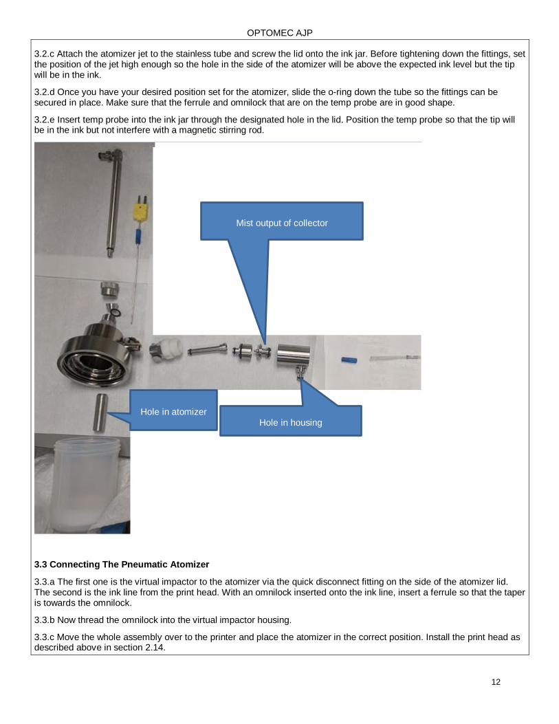
3.2.c Attach the atomizer jet to the stainless tube and screw the lid onto the ink jar. Before tightening down the fittings, set the position of the jet high enough so the hole in the side of the atomizer will be above the expected ink level but the tip will be in the ink.
3.2.d Once you have your desired position set for the atomizer, slide the o-ring down the tube so the fittings can be secured in place. Make sure that the ferrule and omnilock that are on the temp probe are in good shape.
3.2.e Insert temp probe into the ink jar through the designated hole in the lid. Position the temp probe so that the tip will be in the ink but not interfere with a magnetic stirring rod.
3.3 Connecting The Pneumatic Atomizer
3.3.a The first one is the virtual impactor to the atomizer via the quick disconnect fitting on the side of the atomizer lid. The second is the ink line from the print head. With an omnilock inserted onto the ink line, insert a ferrule so that the taper is towards the omnilock.
3.3.b Now thread the omnilock into the virtual impactor housing.
3.3.c Move the whole assembly over to the printer and place the atomizer in the correct position. Install the print head as described above in section 2.14.
Mist output of collector
Hole in housing Hole in atomizer
OPTOMEC AJP
13
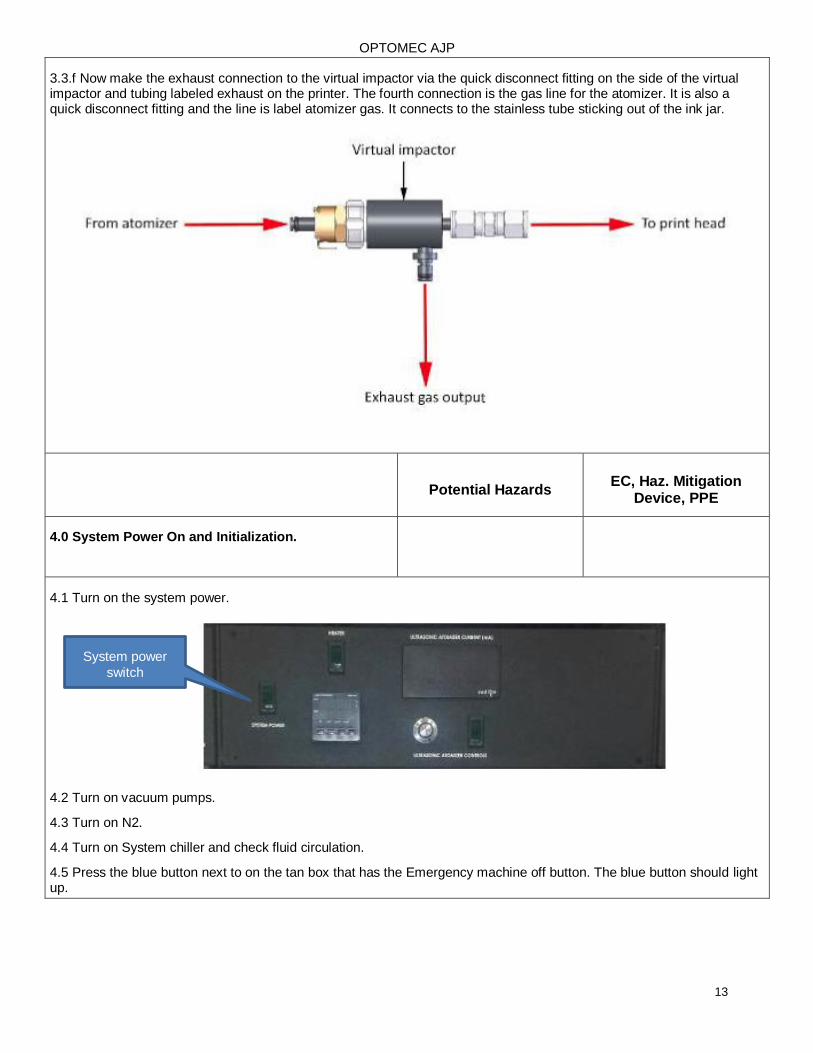
3.3.f Now make the exhaust connection to the virtual impactor via the quick disconnect fitting on the side of the virtual impactor and tubing labeled exhaust on the printer. The fourth connection is the gas line for the atomizer. It is also a quick disconnect fitting and the line is label atomizer gas. It connects to the stainless tube sticking out of the ink jar.
Potential Hazards EC, Haz. Mitigation
Device, PPE
4.0 System Power On and Initialization.
4.1 Turn on the system power.
4.2 Turn on vacuum pumps.
4.3 Turn on N2.
4.4 Turn on System chiller and check fluid circulation.
4.5 Press the blue button next to on the tan box that has the Emergency machine off button. The blue button should light up.
System power
switch
OPTOMEC AJP
14
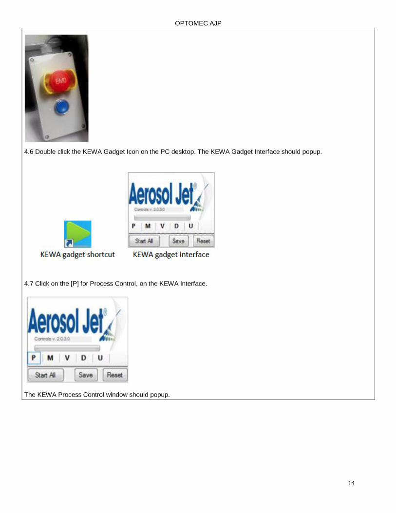
4.6 Double click the KEWA Gadget Icon on the PC desktop. The KEWA Gadget Interface should popup.
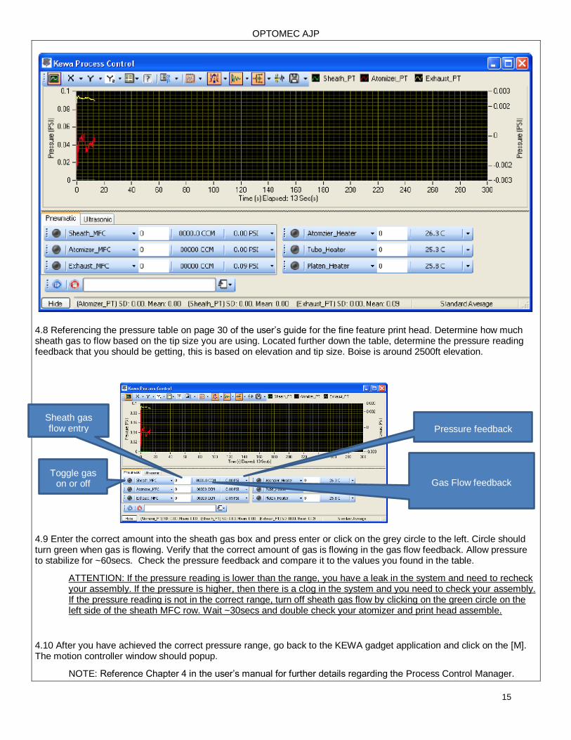
4.7 Click on the [P] for Process Control, on the KEWA Interface.
The KEWA Process Control window should popup.
OPTOMEC AJP
15
4.8 Referencing the pressure table on page 30 of the user’s guide for the fine feature print head. Determine how much sheath gas to flow based on the tip size you are using. Located further down the table, determine the pressure reading feedback that you should be getting, this is based on elevation and tip size. Boise is around 2500ft elevation.
4.9 Enter the correct amount into the sheath gas box and press enter or click on the grey circle to the left. Circle should turn green when gas is flowing. Verify that the correct amount of gas is flowing in the gas flow feedback. Allow pressure to stabilize for ~60secs. Check the pressure feedback and compare it to the values you found in the table.
ATTENTION: If the pressure reading is lower than the range, you have a leak in the system and need to recheck your assembly. If the pressure is higher, then there is a clog in the system and you need to check your assembly. If the pressure reading is not in the correct range, turn off sheath gas flow by clicking on the green circle on the left side of the sheath MFC row. Wait ~30secs and double check your atomizer and print head assemble.
4.10 After you have achieved the correct pressure range, go back to the KEWA gadget application and click on the [M]. The motion controller window should popup.
NOTE: Reference Chapter 4 in the user’s manual for further details regarding the Process Control Manager.
Sheath gas flow entry Pressure feedback
Toggle gas on or off Gas Flow feedback
OPTOMEC AJP
16
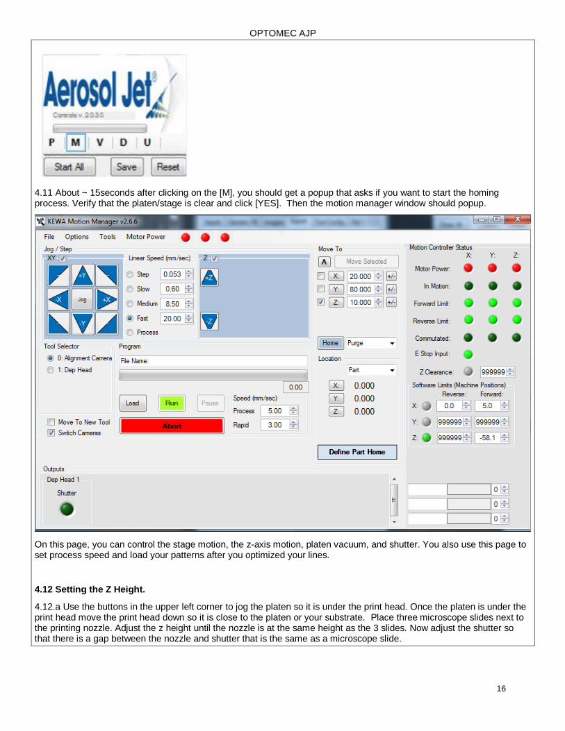
4.11 About ~ 15seconds after clicking on the [M], you should get a popup that asks if you want to start the homing process. Verify that the platen/stage is clear and click [YES]. Then the motion manager window should popup.
On this page, you can control the stage motion, the z-axis motion, platen vacuum, and shutter. You also use this page to set process speed and load your patterns after you optimized your lines.
4.12 Setting the Z Height.
4.12.a Use the buttons in the upper left corner to jog the platen so it is under the print head. Once the platen is under the print head move the print head down so it is close to the platen or your substrate. Place three microscope slides next to the printing nozzle. Adjust the z height until the nozzle is at the same height as the 3 slides. Now adjust the shutter so that there is a gap between the nozzle and shutter that is the same as a microscope slide.
OPTOMEC AJP
17
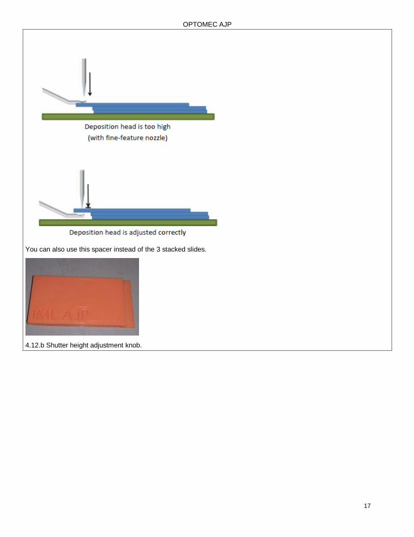
You can also use this spacer instead of the 3 stacked slides.
4.12.b Shutter height adjustment knob.
OPTOMEC AJP
18
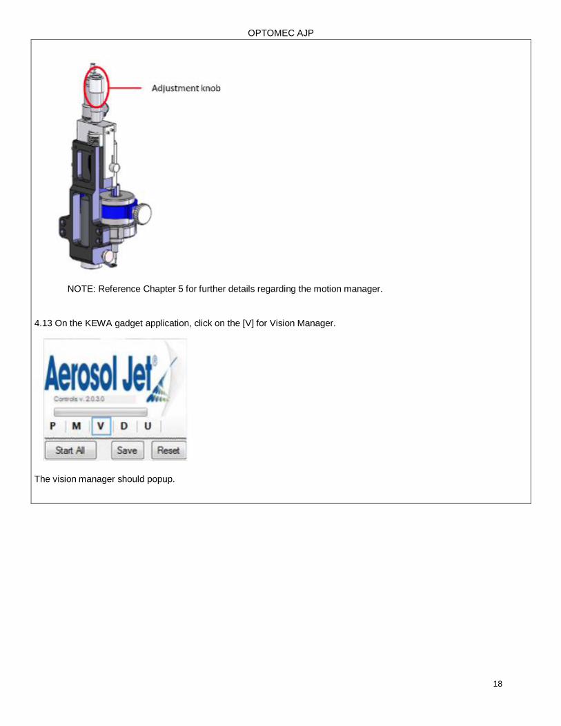
NOTE: Reference Chapter 5 for further details regarding the motion manager.
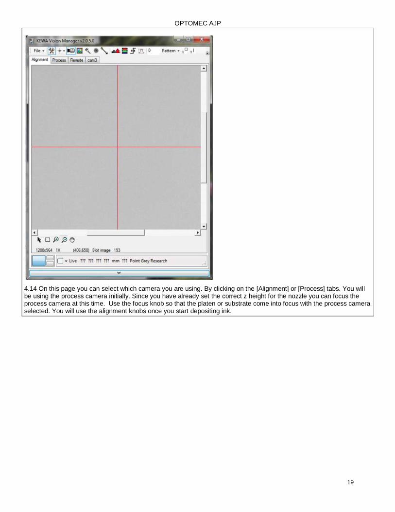
4.13 On the KEWA gadget application, click on the [V] for Vision Manager.
The vision manager should popup.
OPTOMEC AJP
19
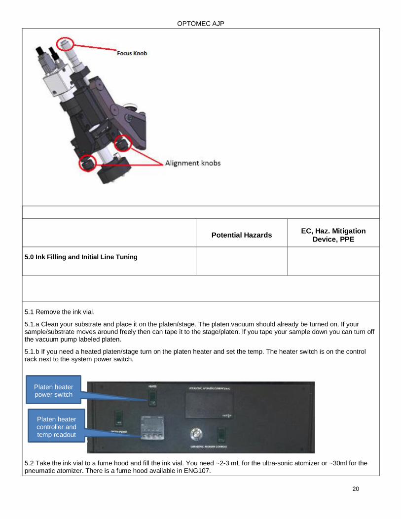
4.14 On this page you can select which camera you are using. By clicking on the [Alignment] or [Process] tabs. You will be using the process camera initially. Since you have already set the correct z height for the nozzle you can focus the process camera at this time. Use the focus knob so that the platen or substrate come into focus with the process camera selected. You will use the alignment knobs once you start depositing ink.
OPTOMEC AJP
20
Potential Hazards
EC, Haz. Mitigation Device, PPE
5.0 Ink Filling and Initial Line Tuning
5.1 Remove the ink vial.
5.1.a Clean your substrate and place it on the platen/stage. The platen vacuum should already be turned on. If your sample/substrate moves around freely then can tape it to the stage/platen. If you tape your sample down you can turn off the vacuum pump labeled platen.
5.1.b If you need a heated platen/stage turn on the platen heater and set the temp. The heater switch is on the control rack next to the system power switch.
5.2 Take the ink vial to a fume hood and fill the ink vial. You need ~2-3 mL for the ultra-sonic atomizer or ~30ml for the pneumatic atomizer. There is a fume hood available in ENG107.
Platen heater power switch
Platen heater controller and temp readout
OPTOMEC AJP
21
5.3 Return with your filled ink vial and reinstall is into the correct atomizer. Make sure you have made all the correct connections. Refer to section 2 if you are using the ultra-sonic atomizer or section 3 if you are using the pneumatic atomizer.
If you are using the pneumatic atomizer jump to section 5.5.
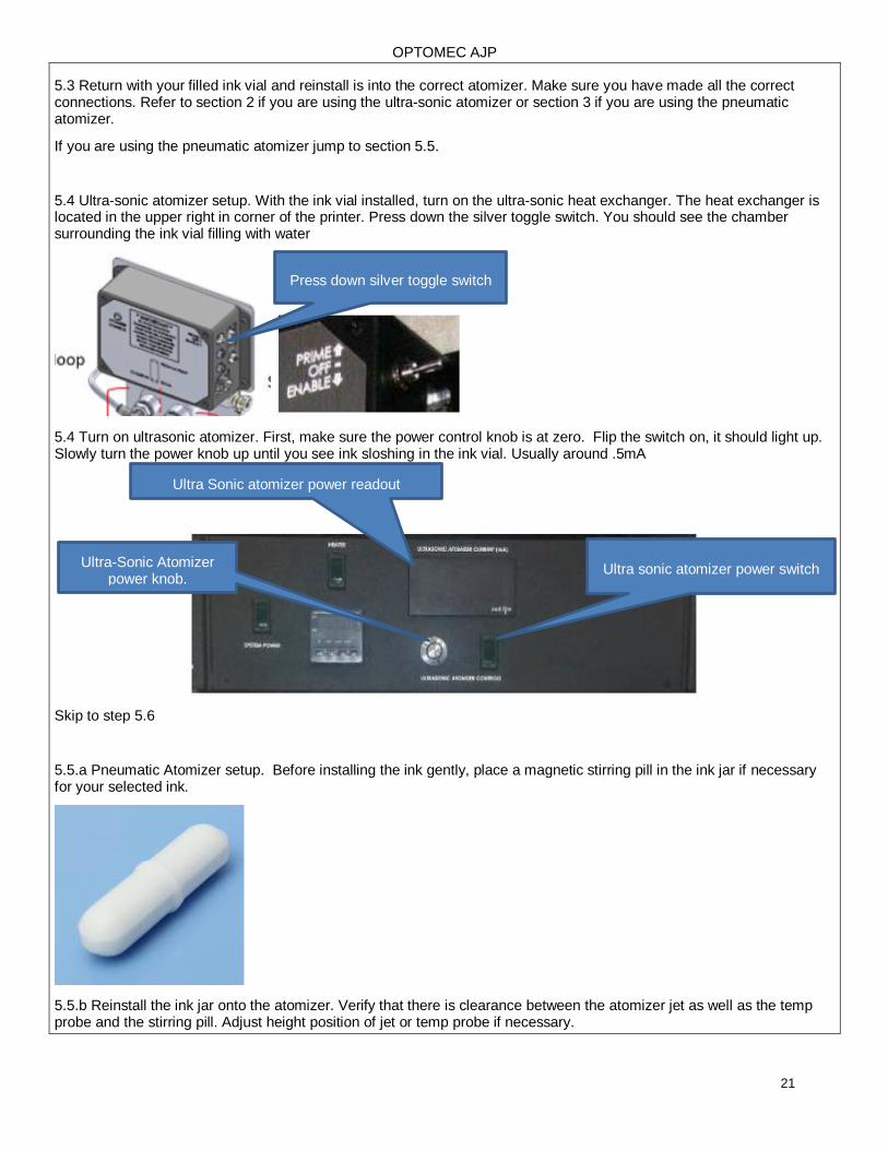
5.4 Ultra-sonic atomizer setup. With the ink vial installed, turn on the ultra-sonic heat exchanger. The heat exchanger is located in the upper right in corner of the printer. Press down the silver toggle switch. You should see the chamber surrounding the ink vial filling with water
5.4 Turn on ultrasonic atomizer. First, make sure the power control knob is at zero. Flip the switch on, it should light up. Slowly turn the power knob up until you see ink sloshing in the ink vial. Usually around .5mA
Skip to step 5.6
5.5.a Pneumatic Atomizer setup. Before installing the ink gently, place a magnetic stirring pill in the ink jar if necessary for your selected ink.
5.5.b Reinstall the ink jar onto the atomizer. Verify that there is clearance between the atomizer jet as well as the temp probe and the stirring pill. Adjust height position of jet or temp probe if necessary.
Press down silver toggle switch
Ultra sonic atomizer power switch Ultra-Sonic Atomizer
power knob.
Ultra Sonic atomizer power readout
OPTOMEC AJP
22
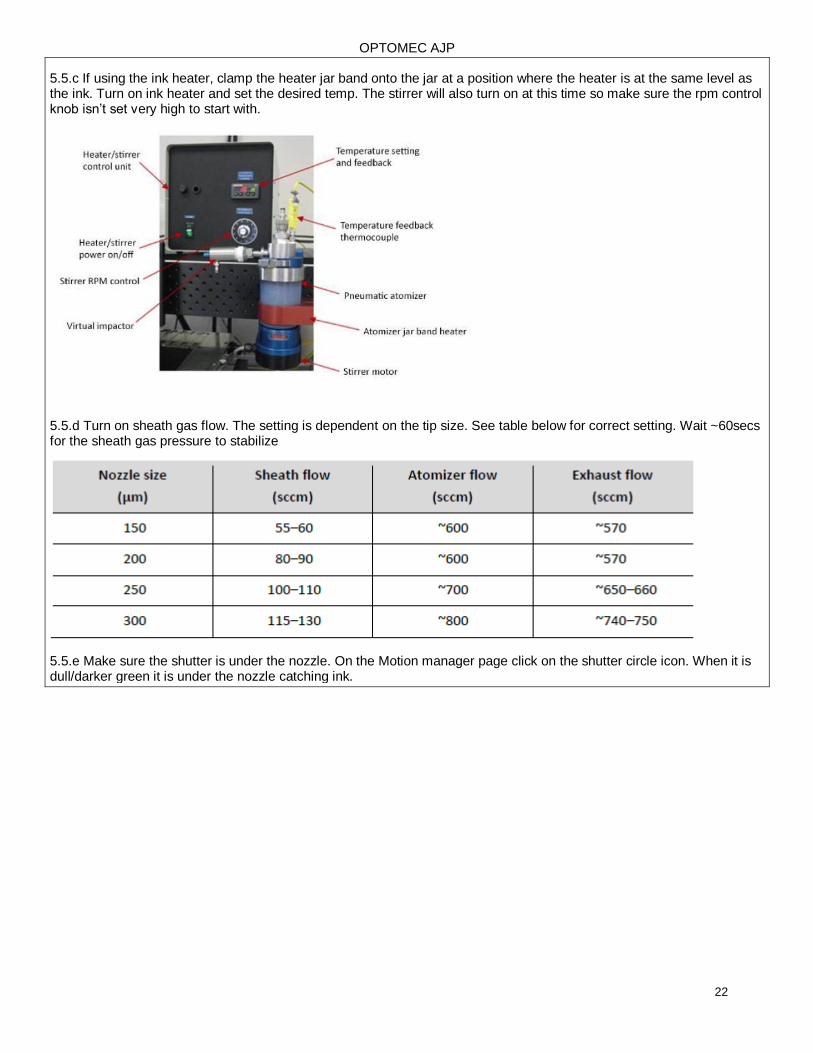
5.5.c If using the ink heater, clamp the heater jar band onto the jar at a position where the heater is at the same level as the ink. Turn on ink heater and set the desired temp. The stirrer will also turn on at this time so make sure the rpm control knob isn’t set very high to start with.
5.5.d Turn on sheath gas flow. The setting is dependent on the tip size. See table below for correct setting. Wait ~60secs for the sheath gas pressure to stabilize
5.5.e Make sure the shutter is under the nozzle. On the Motion manager page click on the shutter circle icon. When it is dull/darker green it is under the nozzle catching ink.
OPTOMEC AJP
23
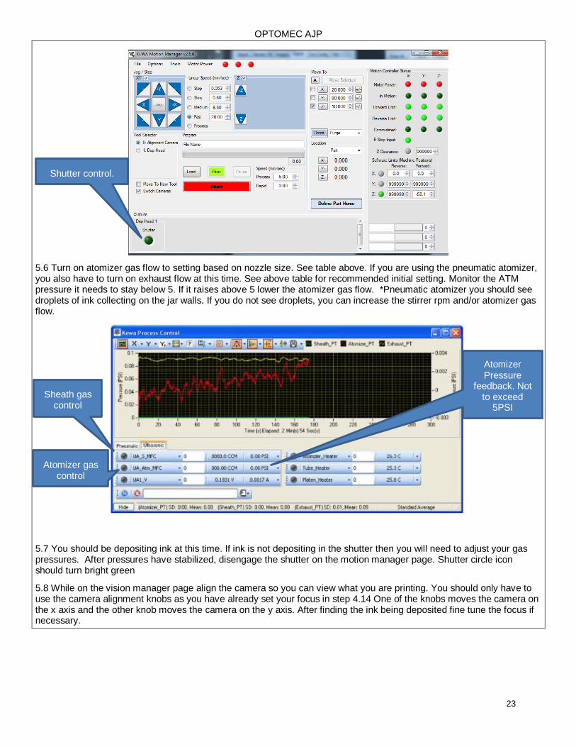
5.6 Turn on atomizer gas flow to setting based on nozzle size. See table above. If you are using the pneumatic atomizer, you also have to turn on exhaust flow at this time. See above table for recommended initial setting. Monitor the ATM pressure it needs to stay below 5. If it raises above 5 lower the atomizer gas flow. *Pneumatic atomizer you should see droplets of ink collecting on the jar walls. If you do not see droplets, you can increase the stirrer rpm and/or atomizer gas flow.
5.7 You should be depositing ink at this time. If ink is not depositing in the shutter then you will need to adjust your gas pressures. After pressures have stabilized, disengage the shutter on the motion manager page. Shutter circle icon should turn bright green
5.8 While on the vision manager page align the camera so you can view what you are printing. You should only have to use the camera alignment knobs as you have already set your focus in step 4.14 One of the knobs moves the camera on the x axis and the other knob moves the camera on the y axis. After finding the ink being deposited fine tune the focus if necessary.
Sheath gas control
Atomizer gas control
Atomizer Pressure
feedback. Not to exceed
5PSI
Shutter control.
OPTOMEC AJP
24
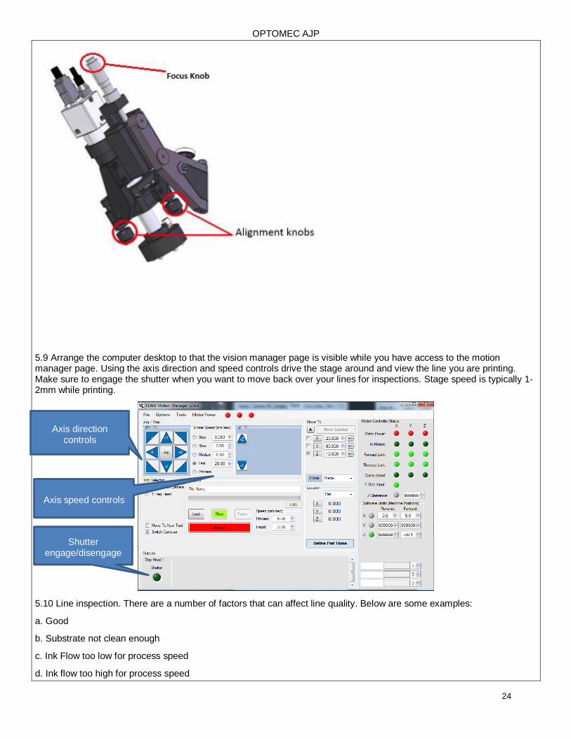
5.9 Arrange the computer desktop to that the vision manager page is visible while you have access to the motion manager page. Using the axis direction and speed controls drive the stage around and view the line you are printing. Make sure to engage the shutter when you want to move back over your lines for inspections. Stage speed is typically 1-2mm while printing.
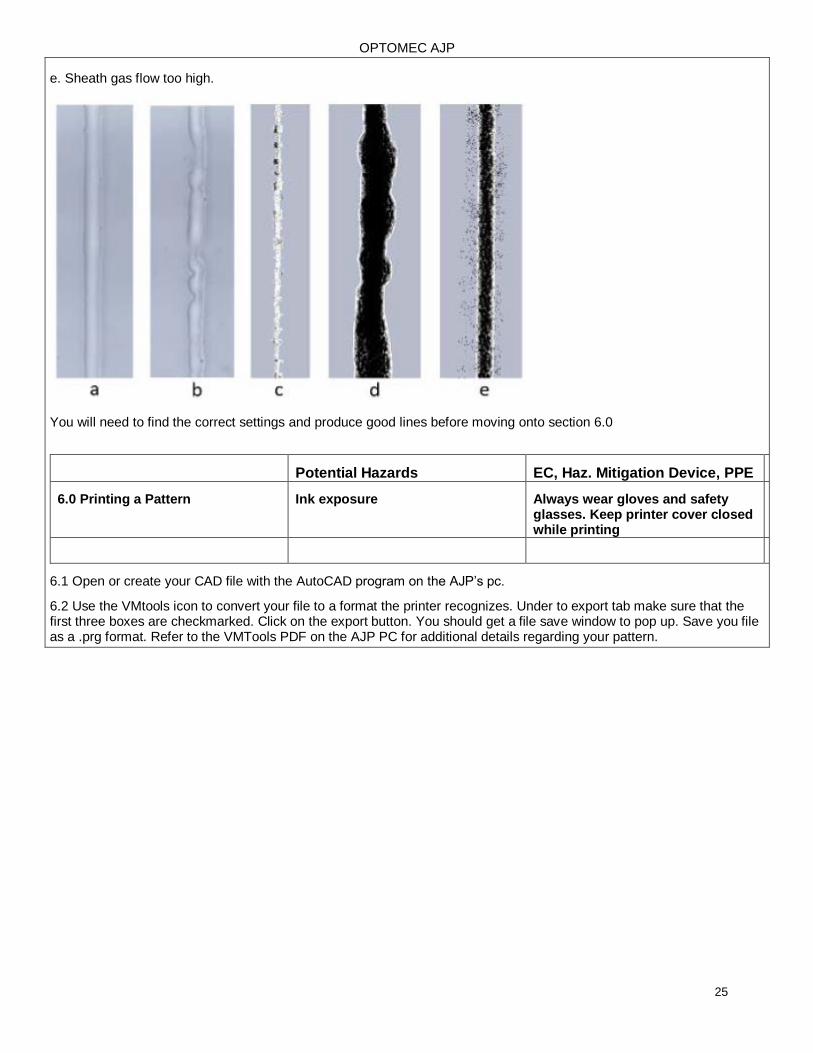
5.10 Line inspection. There are a number of factors that can affect line quality. Below are some examples:
a. Good
b. Substrate not clean enough
c. Ink Flow too low for process speed
d. Ink flow too high for process speed
Axis direction controls
Axis speed controls
Shutter engage/disengage
OPTOMEC AJP
25
e. Sheath gas flow too high.
You will need to find the correct settings and produce good lines before moving onto section 6.0
Potential Hazards EC, Haz. Mitigation Device, PPE
6.0 Printing a Pattern Ink exposure Always wear gloves and safety glasses. Keep printer cover closed while printing
6.1 Open or create your CAD file with the AutoCAD program on the AJP’s pc.
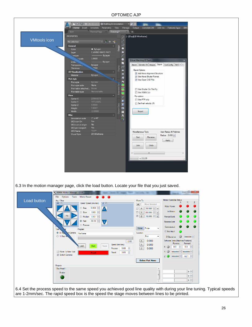
6.2 Use the VMtools icon to convert your file to a format the printer recognizes. Under to export tab make sure that the first three boxes are checkmarked. Click on the export button. You should get a file save window to pop up. Save you file as a .prg format. Refer to the VMTools PDF on the AJP PC for additional details regarding your pattern.
OPTOMEC AJP
26
6.3 In the motion manager page, click the load button. Locate your file that you just saved.
6.4 Set the process speed to the same speed you achieved good line quality with during your line tuning. Typical speeds are 1-2mm/sec. The rapid speed box is the speed the stage moves between lines to be printed.
VMtools icon
Load button
OPTOMEC AJP
27
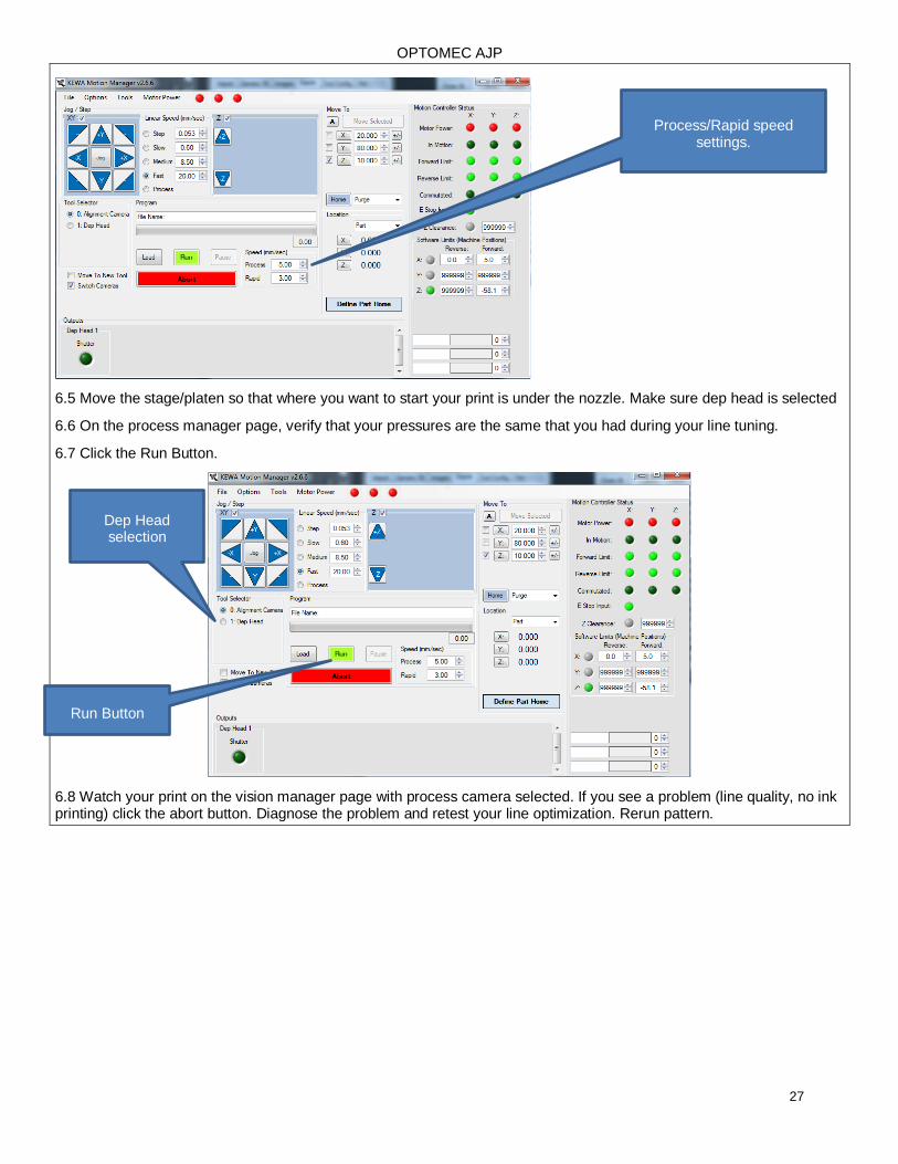
6.5 Move the stage/platen so that where you want to start your print is under the nozzle. Make sure dep head is selected
6.6 On the process manager page, verify that your pressures are the same that you had during your line tuning.
6.7 Click the Run Button.
6.8 Watch your print on the vision manager page with process camera selected. If you see a problem (line quality, no ink printing) click the abort button. Diagnose the problem and retest your line optimization. Rerun pattern.
Process/Rapid speed settings.
Run Button
Dep Head selection
OPTOMEC AJP
28
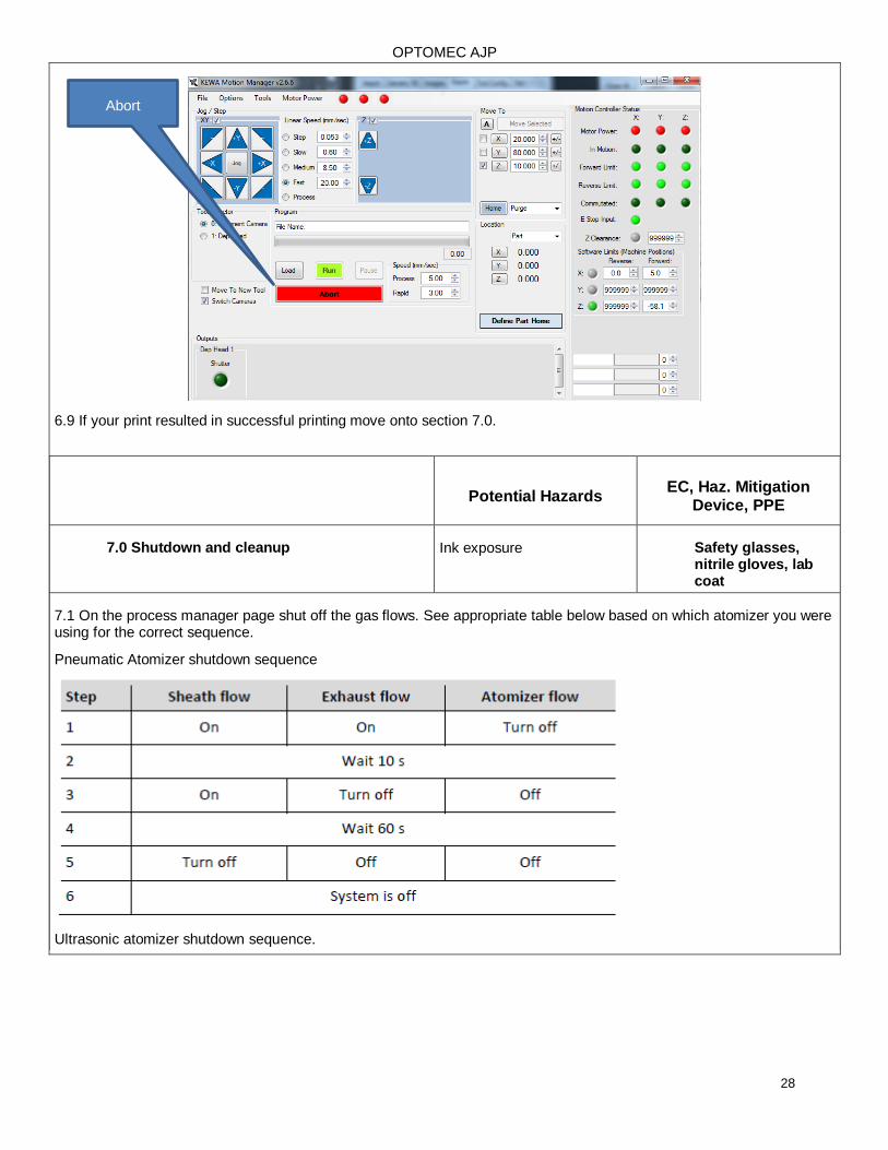
6.9 If your print resulted in successful printing move onto section 7.0.
Potential Hazards EC, Haz. Mitigation
Device, PPE
7.0 Shutdown and cleanup Ink exposure Safety glasses, nitrile gloves, lab coat
7.1 On the process manager page shut off the gas flows. See appropriate table below based on which atomizer you were using for the correct sequence.
Pneumatic Atomizer shutdown sequence
Ultrasonic atomizer shutdown sequence.
Abort
OPTOMEC AJP
29
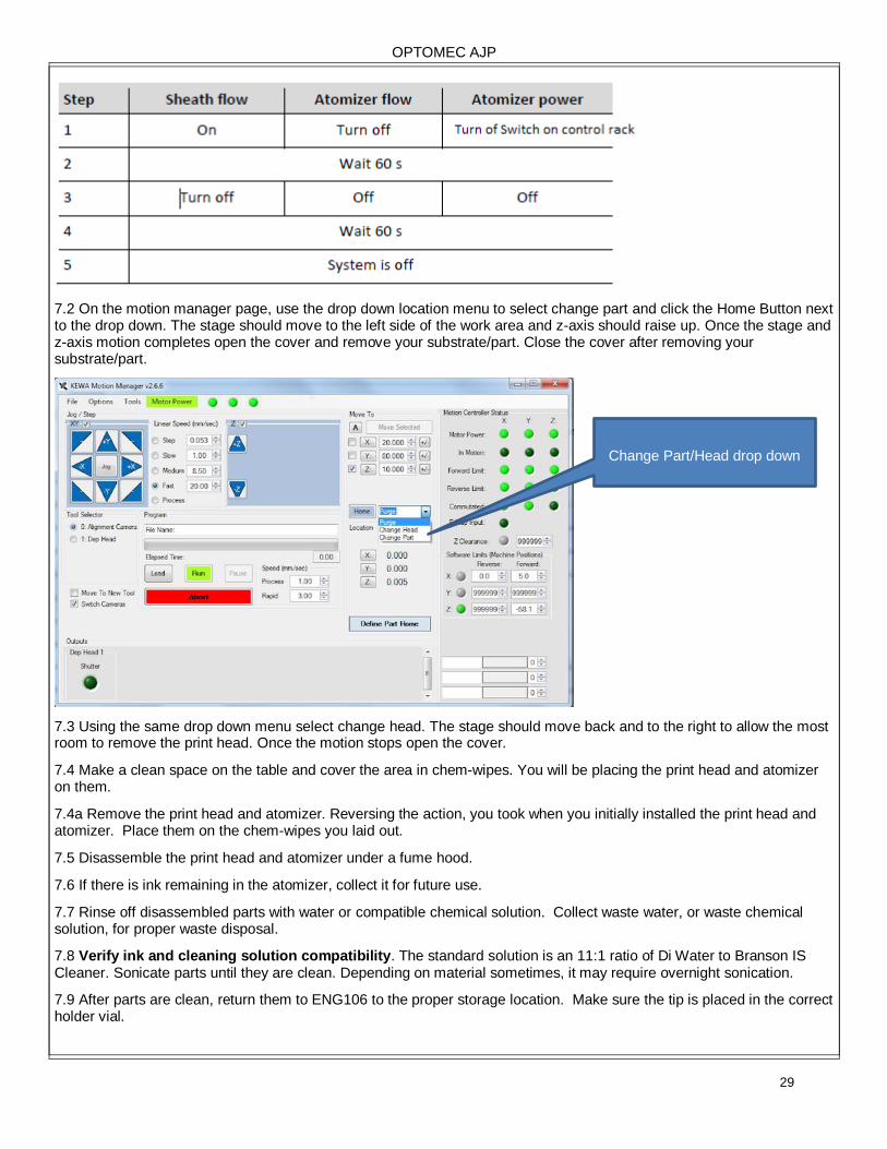
7.2 On the motion manager page, use the drop down location menu to select change part and click the Home Button next to the drop down. The stage should move to the left side of the work area and z-axis should raise up. Once the stage and z-axis motion completes open the cover and remove your substrate/part. Close the cover after removing your substrate/part.
7.3 Using the same drop down menu select change head. The stage should move back and to the right to allow the most room to remove the print head. Once the motion stops open the cover.
7.4 Make a clean space on the table and cover the area in chem-wipes. You will be placing the print head and atomizer on them.
7.4a Remove the print head and atomizer. Reversing the action, you took when you initially installed the print head and atomizer. Place them on the chem-wipes you laid out.
7.5 Disassemble the print head and atomizer under a fume hood.
7.6 If there is ink remaining in the atomizer, collect it for future use.
7.7 Rinse off disassembled parts with water or compatible chemical solution. Collect waste water, or waste chemical solution, for proper waste disposal.
7.8 Verify ink and cleaning solution compatibility. The standard solution is an 11:1 ratio of Di Water to Branson IS Cleaner. Sonicate parts until they are clean. Depending on material sometimes, it may require overnight sonication.
7.9 After parts are clean, return them to ENG106 to the proper storage location. Make sure the tip is placed in the correct holder vial.
Change Part/Head drop down

OPTOMEC AJP
30


![INDEX [] · INDEX Grinders Hammers Drills Drivers Mixers Saws Planers PICTOGRAPH Double Insulation Variable Speed Reversing Operation ... AJP-55 33 AJP-1210 33 AJP-1310 33 AJP-1410](https://img.pdfslide.us/doc/110x75/5b95ee9e09d3f2205c8d5951/index-index-grinders-hammers-drills-drivers-mixers-saws-planers-pictograph.jpg)