Embed Size (px)
Citation preview

Optoelectronic Device and Optoelectronic Device and Fiber Link CharacterizationFiber Link Characterization
in in Computer Integrated Computer Integrated
Electronics LaboratoryElectronics Laboratory
ASEE 2007 Annual Conference,ASEE 2007 Annual Conference, Honolulu, Hawaii, June 24-27, 2007Honolulu, Hawaii, June 24-27, 2007
Mustafa G. GuvenchMustafa G. Guvench

AbstractAbstract
It is shown that, with minimal additional investment It is shown that, with minimal additional investment in an in an Optical Spectrum AnalyzerOptical Spectrum Analyzer and a and a Thermo Thermo Stream temperature controllerStream temperature controller, , light sourceslight sources, such as , such as LASER diodes, LEDs, incandescent and discharge LASER diodes, LEDs, incandescent and discharge lamps, lamps, and detectorsand detectors, such as photodiodes and solar , such as photodiodes and solar cells, and optoelectronic combinations of them, like cells, and optoelectronic combinations of them, like Optical Isolators and Optical Fiber Links Optical Isolators and Optical Fiber Links can be can be measured and characterizedmeasured and characterized for their electrical, opto- for their electrical, opto-electrical and spectral characteristics and SPICE electrical and spectral characteristics and SPICE equivalent parameters in a standard equivalent parameters in a standard Computer-Computer-Integrated-Electronics laboratoryIntegrated-Electronics laboratory. .

Introduction & BackgroundIntroduction & Background
Computer-Integrated-Electronics Laboratory established with grants from N.S.F. Integrates PC with Electronic Test Bench Equipment Therefore facilitates automated electronic tests and measurements
and provides in-situ Math, Design and Simulation tools (Mathematica, PSpice, L-Edit, …)
Courses served: Electronics I & II, Analog & Digital CMOS VLSI, Silicon I.C. Microfabrication, Senior Design Projects

Computer-Integrated-Electronics LaboratoryComputer-Integrated-Electronics Laboratory
The Computer Integrated Electronics Laboratory Workstation

SPICE Verification of Designs and Automated SPICE Verification of Designs and Automated Frequency Response Tests in the Computer-Frequency Response Tests in the Computer-
Integrated-Electronics LaboratoryIntegrated-Electronics Laboratory
Measured P-N Junction Diode
I-V Characteristics
Extraction of SPICE Parameters from Diode
Measurements.

Device Measurements in the Computer-Device Measurements in the Computer-Integrated-Electronics LaboratoryIntegrated-Electronics Laboratory
Measured JFET Drain Chs.
Measured and SPICE Modeled
JFET Transfer Chs.
Measured BJT Collector Chs.Measured P-N Junction
Diode I-V Characteristics
Extraction of SPICE Parameters from Diode
Measurements.
Measured MOS C-V Characteristics

CMOS Analog I.C. Design in the CMOS Analog I.C. Design in the Computer Integrated Electronics LaboratoryComputer Integrated Electronics Laboratory
Design of Operational Amplifiers MOSIS Fabricated Multi-Project Chip

NeedNeed
New course introduced: Optoelectronics Lecture-only Contents: Principles of Optics, Optical Fibers, Semiconductor
Devices, Photodetectors and Solar Cells, Light Emitters including LASERS, Spectral and Electrical Properties and Applications
Textbook: Kasap, S.O., "Optoelectronics and Photonics", Prentice Hall 2001
Need: In-Class Demos and Hands on Experiments
No Resources

Added to C.I.E. Lab.Added to C.I.E. Lab.
1. A High Resolution Optical Spectrometer: Ocean Optics Model HR-2000CG-UV-NIR USB 0.1 nm resolution Optical Fiber Input USB interface powered and Portable
2. A Temperature Controlled Device Test Chamber: Thermo-Stream Model AM-003
Optically Transparent Glass Chamber Heated/Cooled Dry Air Supply with Temperature Control -70C < T < +120C

Temperature Controlled Optoelectronic Temperature Controlled Optoelectronic Device Test ChamberDevice Test Chamber

Optoelectronic Device Optoelectronic Device Automated I-V Measurement SetupAutomated I-V Measurement Setup
Schematic Diagram of the Optoelectronic Device Automated Measurement Setup
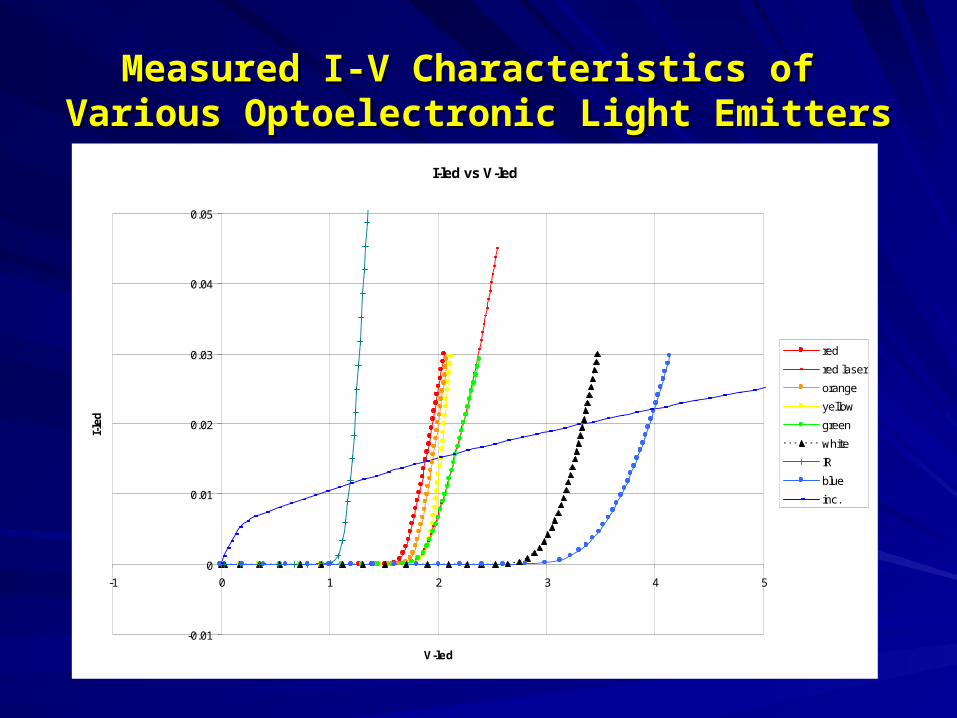
Measured I-V Characteristics of Measured I-V Characteristics of Various Optoelectronic Light EmittersVarious Optoelectronic Light Emitters
I-led vs V-led
-0.01
0
0.01
0.02
0.03
0.04
0.05
-1 0 1 2 3 4 5
V-led
I-le
d
red
red laser
orange
yellow
green
white
IR
blue
inc.

Measured I-V Characteristics of P-N Junction Emitters Measured I-V Characteristics of P-N Junction Emitters Plotted for SPICE Parameter Extraction of IS, N, RSPlotted for SPICE Parameter Extraction of IS, N, RS

Measured I-V Characteristics of an Orange LED and its Measured I-V Characteristics of an Orange LED and its Response to Ambient Temperature Response to Ambient Temperature
Orange: I-led vs V-led
-0.005
0
0.005
0.01
0.015
0.02
0.025
0.03
0.035
0.04
0.045
0.05
0 0.5 1 1.5 2 2.5 3
V-led
I-le
d
70 C
25 C
-30 C

Measured Current Transfer Characteristics of an Measured Current Transfer Characteristics of an Orange LED–Silicon PhotoCell Optocouple and its Orange LED–Silicon PhotoCell Optocouple and its
Response to Ambient Temperature Response to Ambient Temperature

Optical Power Output vs Electrical Power Input Optical Power Output vs Electrical Power Input Characteristics of an Orange LED as a Function of Characteristics of an Orange LED as a Function of
Ambient Temperature Ambient Temperature

Measured I-V Characteristics of a Miniature Measured I-V Characteristics of a Miniature Incandescent Light Bulb and its Response to Ambient Incandescent Light Bulb and its Response to Ambient
Temperature Temperature

Measured Spectral Emission Characteristics of Various Measured Spectral Emission Characteristics of Various LEDs and a LASER Diode and an Incandescent Lamp LEDs and a LASER Diode and an Incandescent Lamp
-500
0
500
1000
1500
2000
2500
3000
3500
4000
4500
350 450 550 650 750 850 950 1050
Wavelength (nanometers)
Rel
ativ
e S
pec
tral
Ou
tpu
t Blue
Green
Red
Orange
White
Yellow
Lamp
Laser
Infrared

Measured Spectral Emission Characteristics of a Red Measured Spectral Emission Characteristics of a Red LED and its Response to Ambient Temperature LED and its Response to Ambient Temperature
-500
0
500
1000
1500
2000
2500
3000
3500
4000
500 550 600 650 700 750 800
Wavelength (nm)
Inte
nsi
ty Red LED @-30C
Red LED @+25C
Red LED @+70C

NSC-USM SOLAR CELLNSC-USM SOLAR CELL
Finished Solar CellFinished Solar Cell Cross SectionCross Section

400W Metal Halide +
2x 300W Quartz Halogen
=
Sun on 8” Wafer.
Our Solar SimulatorOur Solar Simulator

Solar Simulator ResultsSolar Simulator Results

ConclusionsConclusions
With minimal additional investment in an With minimal additional investment in an Optical Spectrum AnalyzerOptical Spectrum Analyzer and a and a Thermo Stream temperature controllerThermo Stream temperature controller, it was shown that , it was shown that light light sourcessources, such as LASER diodes, LEDs, incandescent and discharge , such as LASER diodes, LEDs, incandescent and discharge lamps, lamps, and detectorsand detectors, such as photodiodes and solar cells, and , such as photodiodes and solar cells, and optoelectronic combinations of them, like Optical Isolators and Optical optoelectronic combinations of them, like Optical Isolators and Optical Fiber Links Fiber Links can be measured and characterizedcan be measured and characterized for their electrical, opto- for their electrical, opto-electrical and spectral characteristics and SPICE equivalent parameters electrical and spectral characteristics and SPICE equivalent parameters in a in a Computer-Integrated-Electronics laboratoryComputer-Integrated-Electronics laboratory. .
The measurements reported here were successfully incorporated into a The measurements reported here were successfully incorporated into a lecture-only course on Optoelectronics to enhance and supplement the lecture-only course on Optoelectronics to enhance and supplement the theoretical background built in the course.theoretical background built in the course.

AcknowledgementsAcknowledgements
Fairchild Semiconductor Corporation, Fairchild Semiconductor Corporation,
USM Technology GrantUSM Technology Grant
Ocean Optics Inc. Grant matchOcean Optics Inc. Grant matchNational Science Foundation National Science Foundation (USE 905 1602 )(USE 905 1602 )
ASEE 2007 Annual Conference,ASEE 2007 Annual Conference, Honolulu, Hawaii, June 24-27, 2007Honolulu, Hawaii, June 24-27, 2007

THANK YOUTHANK YOU
Mustafa G. Guvench Mustafa G. Guvench
ASEE 2007 Annual Conference,ASEE 2007 Annual Conference, Honolulu, Hawaii, June 24-27, 2007Honolulu, Hawaii, June 24-27, 2007

The Measurement SystemThe Measurement System
Schematic Drawing of the High-Current Solar-Cell Test Set up

Design, Fabrication and Testing of Design, Fabrication and Testing of Solar Cells (Solar Cells (National SemiconductorNational Semiconductor))
-0.2 0.2 0.4 0.6 0.8V
-0.6
-0.4
-0.2
0.2
0.4
0.6
I

Design, Fabrication and Testing of Design, Fabrication and Testing of Solar Cells (Solar Cells (National SemiconductorNational Semiconductor))
-0.2 0.2 0.4 0.6 0.8V
-0.6
-0.4
-0.2
0.2
0.4
0.6
I
Table 2.3
LED Type Current (mA) Wavelength (λ)
Bandgap (eV)
Green 30 mA 5.6337E-07 2.2025
Orange 15.3 mA 6.2353E-07 1.9900
Blue 1.88 mA 4.74E-07 2.6178
White 15.2 mA 5.5028E-07 2.2549
Yellow 20.0 mA 5.9261E-07 2.0938
Red 13.0 mA 6.4763E-07 1.9159
Infrared 36.4 mA 9.4031E-07 1.3196(GaAs)
Equation 2.3: Eg = (hc)/(eλ)
Spectrum
0
100
200
300
400
500
600
700
800
900
1000
200 400 600 800 1000
Wavelength (nm)
Da
rk A
dju
ste
d R
ela
tiv
e In
ten
sit
y
one halogen
two halogen
metal halide
flourescent
metal halide and twohalogens
IV Characteristics
-0.08
-0.06
-0.04
-0.02
0
0.02
0.04
0.06
0.08
0.1
-0.5 -0.3 -0.1 0.1 0.3 0.5 0.7
Voltage (V)
Cu
rre
nt
(A)
One Halogen
Tw o Halogen
All Lamps
dark
One halogen Pow er
Tw o Halogen Pow er
All Lamps Pow er

Solar Simulator Solar Simulator ResultsResults
In the final form, the radiation intensity was tested and found to be within +/- 10% up to 8 inch diameter and much better (+/-3%) for a smaller 6 inch diameter wafers.
2.5
5
7.5
10
2.5
5
7.5
10
60
70
80
90
100
2.5
5
7.5
10
2 4 6 8 10 12
2
4
6
8
10
12
• Purple Circle shows our 200mm waferwithin 80% range.• Considering a solar intensity = 100mW/cm2• Silicon solar is expected to generate20mA/cm2• 8inch wafer = 1 Si Solar Cell = >6A Photo Current

Presentation OverviewPresentation Overview
Introduction and Background
Goals
The Solar Cell Test Setup: • Design, Features & Results
The Solar Simulator:
The USM-NSC Solar Cell• Design• Results
Conclusions