Embed Size (px)
Citation preview

OptiX PTN 1900 Packet Transport Platform of PTNSeriesV100R002C01
Hardware Description
Issue 04
Date 2010-10-15
HUAWEI TECHNOLOGIES CO., LTD.


Copyright © Huawei Technologies Co., Ltd. 2010. All rights reserved.No part of this document may be reproduced or transmitted in any form or by any means without prior writtenconsent of Huawei Technologies Co., Ltd. Trademarks and Permissions
and other Huawei trademarks are trademarks of Huawei Technologies Co., Ltd.All other trademarks and trade names mentioned in this document are the property of their respective holders. NoticeThe purchased products, services and features are stipulated by the contract made between Huawei and thecustomer. All or part of the products, services and features described in this document may not be within thepurchase scope or the usage scope. Unless otherwise specified in the contract, all statements, information,and recommendations in this document are provided "AS IS" without warranties, guarantees or representationsof any kind, either express or implied.
The information in this document is subject to change without notice. Every effort has been made in thepreparation of this document to ensure accuracy of the contents, but all statements, information, andrecommendations in this document do not constitute the warranty of any kind, express or implied.
Huawei Technologies Co., Ltd.Address: Huawei Industrial Base
Bantian, LonggangShenzhen 518129People's Republic of China
Website: http://www.huawei.com
Email: [email protected]
Issue 04 (2010-10-15) Huawei Proprietary and ConfidentialCopyright © Huawei Technologies Co., Ltd.
i


About This Document
Related VersionsThe following table lists the product versions related to this document.
Product Name Version
OptiX PTN 1900 V100R002C01
Huawei iManager U2000 V100R002C00
Intended AudienceThis document describes the equipment structure, subrack structure and board classification.This document also describes each board of different classes in details.
This document helps you get the detailed information on the equipment hardware.
The intended audiences of this document are:
l Network planning engineers
l Hardware installation engineers
l System maintenance engineers
Symbol ConventionsThe symbols that may be found in this document are defined as follows.
Symbol Description
DANGERIndicates a hazard with a high level of risk, which if notavoided, will result in death or serious injury.
WARNINGIndicates a hazard with a medium or low level of risk, whichif not avoided, could result in minor or moderate injury.
OptiX PTN 1900 Packet Transport Platform of PTN SeriesHardware Description About This Document
Issue 04 (2010-10-15) Huawei Proprietary and ConfidentialCopyright © Huawei Technologies Co., Ltd.
iii

Symbol Description
CAUTIONIndicates a potentially hazardous situation, which if notavoided, could result in equipment damage, data loss,performance degradation, or unexpected results.
TIP Indicates a tip that may help you solve a problem or savetime.
NOTE Provides additional information to emphasize or supplementimportant points of the main text.
GUI ConventionsThe GUI conventions that may be found in this document are defined as follows.
Convention Description
Boldface Buttons, menus, parameters, tabs, window, and dialog titlesare in boldface. For example, click OK.
> Multi-level menus are in boldface and separated by the ">"signs. For example, choose File > Create > Folder.
Change HistoryUpdates between document issues are cumulative. Therefore, the latest document issue containsall updates made in previous issues.
Changes in Issue 04 (2010-10-15) Based on Product Version V100R002C01The updates of the document are as follow:
Safety Label
Updates the description of the labels.
Others
l Updates dimensions of certain boards.l Modifies the known anomalies.
Changes in Issue 03 (2010-05-20) Based on Product Version V100R002C01The updates of the document are as follow:
Board Overview
Updates the inter-board relation diagram.
About This DocumentOptiX PTN 1900 Packet Transport Platform of PTN Series
Hardware Description
iv Huawei Proprietary and ConfidentialCopyright © Huawei Technologies Co., Ltd.
Issue 04 (2010-10-15)

Changes in Issue 02 (2010-03-30) Based on Product Version V100R002C01The updates of the document are as follow:
Processing Boards
Description of the functions of the MD1 and CD1: Adds the description of the port bandwidthutilization statistics.
Interface Boards
Description of the functions of the ETFC, EFG2, EFF8, and POD41: Adds the description ofthe port bandwidth utilization statistics.
Others
l Updates the table providing the board weight and power consumption.l Optimizes certain figures.l Modifies the known anomalies.
Changes in Issue 01 (2010-01-15) Based on Product Version V100R002C01This document is the first release of the V100R002C01 version.
The updates of the document are as follows:
Interface Boards
l Adds the description of the GE electrical interface to the description of the front panel andtechnical specifications of the EFG2.
Others
l Adds the description of the filler panel.l Adds the description of the pluggable optical and pulggable electrical module.l Optimizes the description of indicators.l Optimizes certain figures.l Modifies the known anomalies.
Changes in Issue 02 (2009-10-30) Based on Product Version V100R002C00The updates of the document are as follow:
Cabinet
In the part about the DC PDU, a note about the equipment supporting only the DC-I powerdistribution mode is added.
Subrack
l The subrack structure diagram is updated.l The information about the processing capacity of slots is added.l The power consumption of the entire equipment is added in the part of technical
specifications of the subrack.
Board Overview
OptiX PTN 1900 Packet Transport Platform of PTN SeriesHardware Description About This Document
Issue 04 (2010-10-15) Huawei Proprietary and ConfidentialCopyright © Huawei Technologies Co., Ltd.
v

l The inter-board relation diagram is updated.l The operating temperature of boards is updated.
Processing Boards
l The number of concatenated PWs supported by the AD1 is updated to 512.
Interface Boards
l The technical specifications of the optical interfaces on the EFG2 are updated.l The technical specifications of the optical interfaces on the POD41 are updated.
Cross-Connect and System Control Boards
The description about jumpers on the TN71CXP and TN72CXP is updated.
Others
l In the part of technical specifications of each board, the board power consumption is added.l In the part of interfaces on the front panel of each board, fiber/cable connections to the
interfaces are added.l In the part of labels for optical modules, the label diagrams, and the mapping relations
between optical modules and boards are added.l Certain figures and tables are optimized.l Known defects are fixed.
Changes in Issue 01 (2009-06-30) Based on Product Version V100R002C00This document is the first release of the V100R002C00 version.
The updates of the document are as follow:
Subrack:
Information about the AFO1 is new in section Valid Slots for Boards and section MappingRelation Between Processing Boards and Interface Boards.
Board Overview
Information about the AFO1 is new in section Boards and section Inter-Board Relation. Theinter-board relation diagram is refreshed.
Processing Boards
Specifications of the CD1 are refreshed.
Interface Boards
Details on the AFO1 is new.
Others
l Certain figures and tables are optimized.l Known defects are fixed.
Changes in Issue 07 (2009-06-01) Based on Product Version V100R001Updates in this document are as follows:
About This DocumentOptiX PTN 1900 Packet Transport Platform of PTN Series
Hardware Description
vi Huawei Proprietary and ConfidentialCopyright © Huawei Technologies Co., Ltd.
Issue 04 (2010-10-15)

l Certain figures and tables are optimized.l Known defects are fixed.
Changes in Issue 06 (2009-04-20) Based on Product Version V100R001Updates in this document are as follows:
l Specifications of the optical interfaces are refreshed.l Optical module labels are refreshed.
Changes in Issue 05 (2009-03-16) Based on Product Version V100R001Updates in this document are as follows:
Known defects are fixed.
Changes in Issue 04 (2009-02-20) Based on Product Version V100R001Updates in this document are as follows:
Cabinet:
l The appearance of the cabinets is refreshed in section Cabinet.l The appearance of the DC PDU is refreshed, and the information about the Short-circuit
Copper Connector is new in section Cabinet Indicators and DC Power Distribution.l Information about the number of allowed subracks is new in section Technical
Specification.
Subrack
Information about the EFF8 is new in section Valid Slots for Boards and section MappingRelation Between Processing Boards and Interface Boards.
Board Overview
Information about the EFF8 is new in section Boards and section Inter-Board Relation. Theinter-board relation diagram is refreshed.
Processing Boards
l Specifications of the MD1 are refreshed (the maximum of ATM remote service connectionssupported by the equipment from 512 to 1k, and the maximum of ATM local serviceconnections supported by the equipment from 256 to 512).
l Specifications of the CD1 are refreshed (the maximum of ATM remote service connectionssupported by the equipment from 512 to 1k, and the maximum of ATM local serviceconnections supported by the equipment from 256 to 512).
Interface Boards
Details on the EFF8 is new.
Cross-connect and System Control Boards
l Details on TN72CXP is newl Information about that TN72CXP supports the IEEE 1588 V2 clock function.
Others
OptiX PTN 1900 Packet Transport Platform of PTN SeriesHardware Description About This Document
Issue 04 (2010-10-15) Huawei Proprietary and ConfidentialCopyright © Huawei Technologies Co., Ltd.
vii
l In section Board Indicators, information about indicators on the EFF8 is new. In sectionPower Consumption and Weight, specifications of the EFF8 are new.
l Specifications of the 75-ohm 8 x E1 Cable are refreshed.
l Product nameplate label is refreshed.
l Known defects are fixed.
Changes in Issue 03 (2008-10-20) Based on Product Version V100R001
Updates in this document are as follows:
Processing Boards
l Specifications such as local service, remote service, local connection, and remoteconnection are new for the AD1, MD1, and CD1. The parameters that can be set for eachboard are corrected.
l Specifications of the MD1 are refreshed (supported PW connections from 254 to 256, anda maximum of 256 ATM remote services supported by the equipment).
l Specifications of the CD1 are refreshed (supported PW connections from 254 to 256, PWssupported by each port from 127 to 128, and a maximum of 256 ATM remote servicessupported by the equipment).
l Specifications of the AD1 are refreshed (the maximum of ATM service connectionssupported by the equipment from 1022 to 1k).
Interface Boards
l ETFC, EFG2, and POD41: The specifications are refreshed (MPLS-Tunnel from 256 to1k, PWs from 1k to 2k, and APS protection groups from 64 to 256).
l L12 and L75: Slot limitations are new. Information about the DB44 pins is corrected.
Changes in Issue 02 (2008-08-20) Based on Product Version V100R001
The updates of the document are as follow:
Cabinet
Information about the N63E 2.0 m cabinet is new. The case where the OptiX PTN 1900 subrackand the OptiX PTN 3900 subrack are installed in the same cabinet is also described. In addition,diagrams of cable connections are updated.
Processing Boards
In the "AD1" section, information about the ATM concatenation is new.
Others
l The number of APS protection groups is corrected through the document.The number ofAPS protection groups is changed from 128 to 64.
l Some diagrams in this document are optimized.
Changes in Issue 01 (2008-05-10) Based on Product Version V100R001
This document is the first release of the V100R001 version.
About This DocumentOptiX PTN 1900 Packet Transport Platform of PTN Series
Hardware Description
viii Huawei Proprietary and ConfidentialCopyright © Huawei Technologies Co., Ltd.
Issue 04 (2010-10-15)

Contents
About This Document...................................................................................................................iii
1 Equipment Structure.................................................................................................................1-1
2 Cabinet.........................................................................................................................................2-12.1 Cabinet Types..................................................................................................................................................2-22.2 Cabinet Indicators and DC Power Distribution...............................................................................................2-3
2.2.1 Cabinet Indicators.................................................................................................................................. 2-32.2.2 DC Power Distribution Unit...................................................................................................................2-4
2.3 Technical Specification...................................................................................................................................2-7
3 Subrack.........................................................................................................................................3-13.1 Subrack Structure and Slots............................................................................................................................ 3-23.2 Valid Slots for Boards.....................................................................................................................................3-43.3 Technical Specification...................................................................................................................................3-5
4 Board Overview..........................................................................................................................4-14.1 Appearance and Dimensions of Boards..........................................................................................................4-24.2 Board Classification........................................................................................................................................4-44.3 Inter-Board Relation........................................................................................................................................4-54.4 Board Running Environment.......................................................................................................................... 4-6
5 Processing Boards.......................................................................................................................5-15.1 MD1................................................................................................................................................................ 5-2
5.1.1 Version Description................................................................................................................................5-25.1.2 Functions and Features...........................................................................................................................5-25.1.3 Working Principle and Signal Flow.......................................................................................................5-45.1.4 Front Panel............................................................................................................................................. 5-65.1.5 Valid Slots..............................................................................................................................................5-65.1.6 TPS Protection for Boards......................................................................................................................5-75.1.7 Board Configuration Reference............................................................................................................. 5-95.1.8 Technical Specifications........................................................................................................................ 5-9
5.2 CD1................................................................................................................................................................. 5-95.2.1 Version Description..............................................................................................................................5-105.2.2 Functions and Features.........................................................................................................................5-105.2.3 Working Principle and Signal Flow.....................................................................................................5-12
OptiX PTN 1900 Packet Transport Platform of PTN SeriesHardware Description Contents
Issue 04 (2010-10-15) Huawei Proprietary and ConfidentialCopyright © Huawei Technologies Co., Ltd.
ix

5.2.4 Front Panel...........................................................................................................................................5-145.2.5 Valid Slots............................................................................................................................................5-155.2.6 Board Configuration Reference...........................................................................................................5-155.2.7 Technical Specifications......................................................................................................................5-15
5.3 AD1...............................................................................................................................................................5-175.3.1 Version Description..............................................................................................................................5-185.3.2 Functions and Features.........................................................................................................................5-185.3.3 Working Principle and Signal Flow.....................................................................................................5-195.3.4 Front Panel...........................................................................................................................................5-215.3.5 Valid Slots............................................................................................................................................5-225.3.6 Board Configuration Reference...........................................................................................................5-225.3.7 Technical Specifications......................................................................................................................5-22
6 Interface Boards..........................................................................................................................6-16.1 ETFC...............................................................................................................................................................6-2
6.1.1 Version Description................................................................................................................................6-26.1.2 Functions and Features...........................................................................................................................6-26.1.3 Working Principle and Signal Flow.......................................................................................................6-36.1.4 Front Panel.............................................................................................................................................6-46.1.5 Valid Slots..............................................................................................................................................6-66.1.6 Board Configuration Reference.............................................................................................................6-66.1.7 Technical Specifications........................................................................................................................6-6
6.2 EFF8................................................................................................................................................................6-76.2.1 Version Description................................................................................................................................6-76.2.2 Functions and Features...........................................................................................................................6-76.2.3 Working Principle and Signal Flow.......................................................................................................6-86.2.4 Front Panel...........................................................................................................................................6-106.2.5 Valid Slots............................................................................................................................................6-126.2.6 Board Configuration Reference...........................................................................................................6-126.2.7 Technical Specifications......................................................................................................................6-13
6.3 EFG2.............................................................................................................................................................6-146.3.1 Version Description..............................................................................................................................6-156.3.2 Functions and Features.........................................................................................................................6-156.3.3 Working Principle and Signal Flow.....................................................................................................6-166.3.4 Front Panel...........................................................................................................................................6-176.3.5 Valid Slots............................................................................................................................................6-206.3.6 Board Configuration Reference...........................................................................................................6-206.3.7 Technical Specifications......................................................................................................................6-20
6.4 POD41...........................................................................................................................................................6-226.4.1 Version Description..............................................................................................................................6-236.4.2 Functions and Features.........................................................................................................................6-236.4.3 Working Principle and Signal Flow.....................................................................................................6-246.4.4 Front Panel...........................................................................................................................................6-25
ContentsOptiX PTN 1900 Packet Transport Platform of PTN Series
Hardware Description
x Huawei Proprietary and ConfidentialCopyright © Huawei Technologies Co., Ltd.
Issue 04 (2010-10-15)

6.4.5 Valid Slots............................................................................................................................................6-266.4.6 Board Configuration Reference...........................................................................................................6-276.4.7 Technical Specifications......................................................................................................................6-27
6.5 AFO1.............................................................................................................................................................6-296.5.1 Version Description..............................................................................................................................6-296.5.2 Functions and Features.........................................................................................................................6-306.5.3 Working Principle and Signal Flow.....................................................................................................6-316.5.4 Front Panel...........................................................................................................................................6-336.5.5 Valid Slots............................................................................................................................................6-356.5.6 Board Configuration Reference...........................................................................................................6-356.5.7 Technical Specifications......................................................................................................................6-35
6.6 L75/L12.........................................................................................................................................................6-376.6.1 Version Description..............................................................................................................................6-386.6.2 Function and Feature............................................................................................................................6-386.6.3 Working Principle and Signal Flow.....................................................................................................6-386.6.4 Front Panel...........................................................................................................................................6-396.6.5 Valid Slots............................................................................................................................................6-426.6.6 Board Configuration Reference...........................................................................................................6-436.6.7 Technical Specifications......................................................................................................................6-43
7 Cross-Connect and System Control Boards..........................................................................7-17.1 TN71CXP........................................................................................................................................................7-2
7.1.1 Version Description................................................................................................................................7-27.1.2 Functions and Features...........................................................................................................................7-37.1.3 Working Principle and Signal Flow.......................................................................................................7-37.1.4 Jumper....................................................................................................................................................7-57.1.5 Front Panel............................................................................................................................................. 7-77.1.6 Valid Slots............................................................................................................................................7-127.1.7 TPS Protection for Boards....................................................................................................................7-137.1.8 Board Configuration Reference...........................................................................................................7-137.1.9 Technical Specifications......................................................................................................................7-13
7.2 TN72CXP......................................................................................................................................................7-137.2.1 Version Description..............................................................................................................................7-147.2.2 Functions and Features.........................................................................................................................7-147.2.3 Working Principle and Signal Flow.....................................................................................................7-147.2.4 Jumper..................................................................................................................................................7-167.2.5 Front Panel...........................................................................................................................................7-197.2.6 Valid Slots............................................................................................................................................7-247.2.7 TPS Protection for Boards....................................................................................................................7-257.2.8 Board Configuration Reference...........................................................................................................7-257.2.9 Technical Specifications......................................................................................................................7-25
8 Power Supply and Fan Boards.................................................................................................8-18.1 PIU.................................................................................................................................................................. 8-2
OptiX PTN 1900 Packet Transport Platform of PTN SeriesHardware Description Contents
Issue 04 (2010-10-15) Huawei Proprietary and ConfidentialCopyright © Huawei Technologies Co., Ltd.
xi

8.1.1 Version Description................................................................................................................................8-28.1.2 Functions and Features...........................................................................................................................8-28.1.3 Working Principle and Signal Flow.......................................................................................................8-38.1.4 Front Panel.............................................................................................................................................8-48.1.5 Valid Slots..............................................................................................................................................8-58.1.6 Technical Specifications........................................................................................................................8-5
8.2 FANA..............................................................................................................................................................8-58.2.1 Version Description................................................................................................................................8-68.2.2 Functions and Features...........................................................................................................................8-68.2.3 Working Principle and Signal Flow.......................................................................................................8-68.2.4 Front Panel.............................................................................................................................................8-78.2.5 Valid Slots..............................................................................................................................................8-88.2.6 Technical Specifications........................................................................................................................8-8
8.3 FANB..............................................................................................................................................................8-88.3.1 Version Description................................................................................................................................8-98.3.2 Functions and Features...........................................................................................................................8-98.3.3 Working Principle and Signal Flow.......................................................................................................8-98.3.4 Front Panel...........................................................................................................................................8-108.3.5 Valid Slots............................................................................................................................................8-118.3.6 Technical Specifications......................................................................................................................8-11
9 Filler Panel...................................................................................................................................9-19.1 Functions and Features....................................................................................................................................9-29.2 Appearance and Valid Slots............................................................................................................................9-2
10 Pluggable Optical Modules..................................................................................................10-110.1 Appearance and Application.......................................................................................................................10-210.2 Optical Module Labels................................................................................................................................10-2
11 Pluggable Electrical Module................................................................................................11-1
12 Cables....................................................................................................................................... 12-112.1 Fiber............................................................................................................................................................12-2
12.1.1 Types of Fiber....................................................................................................................................12-212.1.2 Connector...........................................................................................................................................12-2
12.2 Power Supply Cable and Grounding Cable.................................................................................................12-412.2.1 Cabinet -48 V/BGND/PGND Power Cable.......................................................................................12-512.2.2 Cabinet Door Grounding Cable..........................................................................................................12-712.2.3 Subrack Power Cable.........................................................................................................................12-8
12.3 Service Cable...............................................................................................................................................12-912.3.1 Ethernet Cable....................................................................................................................................12-912.3.2 75-ohm 8 x E1 Cable........................................................................................................................12-1512.3.3 120-ohm 8 x E1 Cable......................................................................................................................12-17
12.4 Management Cable....................................................................................................................................12-1912.4.1 Straight Through Cable....................................................................................................................12-19
ContentsOptiX PTN 1900 Packet Transport Platform of PTN Series
Hardware Description
xii Huawei Proprietary and ConfidentialCopyright © Huawei Technologies Co., Ltd.
Issue 04 (2010-10-15)
12.4.2 Crossover Cable...............................................................................................................................12-1912.5 Clock Cable...............................................................................................................................................12-20
12.5.1 External Clock Cable.......................................................................................................................12-2012.5.2 Clock Bridging Cable.......................................................................................................................12-21
12.6 Cabinet Indicator Cable.............................................................................................................................12-2312.7 Alarm Input/Output Cable.........................................................................................................................12-24
A Indicators...................................................................................................................................A-1A.1 Cabinet Indicators..........................................................................................................................................A-2A.2 Board Indicators............................................................................................................................................A-2
B Labels..........................................................................................................................................B-1B.1 Safety Label...................................................................................................................................................B-2
B.1.1 Labels....................................................................................................................................................B-2B.1.2 Label Position.......................................................................................................................................B-3
B.2 Engineering Labels........................................................................................................................................B-4
C Power Consumption and Weight..........................................................................................C-1
D Board Configuration Parameters..........................................................................................D-1
E Glossary.......................................................................................................................................E-1
OptiX PTN 1900 Packet Transport Platform of PTN SeriesHardware Description Contents
Issue 04 (2010-10-15) Huawei Proprietary and ConfidentialCopyright © Huawei Technologies Co., Ltd.
xiii


Figures
Figure 1-1 OptiX PTN 1900 subrack installed in the cabinet..............................................................................1-1Figure 2-1 Appearance of the cabinets used to house the OptiX PTN 1900........................................................2-2Figure 2-2 Position of cabinet indicators and DC PDU.......................................................................................2-3Figure 2-3 Appearance of the DC PDU...............................................................................................................2-4Figure 2-4 Appearance of the front panel of the DC PDU...................................................................................2-5Figure 2-5 Internal connection of the DC PDU...................................................................................................2-6Figure 2-6 Appearance of the Short-circuit Copper Connector...........................................................................2-7Figure 3-1 Structure of the OptiX PTN 1900 subrack.........................................................................................3-2Figure 3-2 Slot layout of the OptiX PTN 1900....................................................................................................3-3Figure 4-1 Diagram of the inter-board relation of boards for the OptiX PTN 1900............................................4-6Figure 5-1 Block diagram for the working principle of the MD1........................................................................5-5Figure 5-2 Appearance of the front panel of the MD1.........................................................................................5-6Figure 5-3 TPS protection principle of the service sub-board MD1....................................................................5-8Figure 5-4 Hardware configuration of two 1:1 TPS protection groups provided by the service sub-board MD1...............................................................................................................................................................................5-8Figure 5-5 Block diagram for the working principle of the CD1.......................................................................5-12Figure 5-6 Appearance of the front panel of the CD1........................................................................................5-14Figure 5-7 Block diagram for the working principle of the AD1.......................................................................5-19Figure 5-8 Appearance of the front panel of the AD1........................................................................................5-21Figure 6-1 Block diagram for the working principle of the ETFC.......................................................................6-3Figure 6-2 Appearance of the front panel of the ETFC........................................................................................6-5Figure 6-3 Block diagram for the functions of the EFF8.....................................................................................6-9Figure 6-4 Font Panel of the EFF8.....................................................................................................................6-11Figure 6-5 Block diagram for the working principle of the EFG2.....................................................................6-16Figure 6-6 Appearance of the front panel of the EFG2......................................................................................6-18Figure 6-7 Block diagram for the working principle of the POD41..................................................................6-24Figure 6-8 Appearance of the front panel of the POD41...................................................................................6-25Figure 6-9 Block diagram for the working principle of the AFO1....................................................................6-31Figure 6-10 Front panel of the AFO1.................................................................................................................6-34Figure 6-11 Block diagram for the working principle of the L75/L12..............................................................6-38Figure 6-12 Appearances of the front panel of the L75 and the L12.................................................................6-40Figure 7-1 Block diagram for the working principle of the TN71CXP...............................................................7-3Figure 7-2 J2 on the TN71CXP............................................................................................................................7-6Figure 7-3 Appearance of the front panel of the TN71CXP................................................................................7-8
OptiX PTN 1900 Packet Transport Platform of PTN SeriesHardware Description Figures
Issue 04 (2010-10-15) Huawei Proprietary and ConfidentialCopyright © Huawei Technologies Co., Ltd.
xv

Figure 7-4 Block diagram for the working principle of the TN72CXP.............................................................7-15Figure 7-5 J2 on the TN72CXP..........................................................................................................................7-17Figure 7-6 Appearance of the front panel of the TN72CXP..............................................................................7-19Figure 8-1 Block diagram for the working principle of the PIU..........................................................................8-3Figure 8-2 Appearance of the front panel of the PIU...........................................................................................8-4Figure 8-3 Block diagram for the working principle of the FANA.....................................................................8-6Figure 8-4 Appearance of the front panel of the FANA......................................................................................8-7Figure 8-5 Block diagram for the working principle of the FANB......................................................................8-9Figure 8-6 Appearance of the front panel of the FANB.....................................................................................8-10Figure 9-1 Appearances of filler panels...............................................................................................................9-2Figure 10-1 Appearance of the eSFP optical module.........................................................................................10-2Figure 10-2 Optical module labels.....................................................................................................................10-2Figure 11-1 Appearance of the GE SFP electrical module................................................................................ 11-1Figure 12-1 LC/PC optical connector................................................................................................................ 12-3Figure 12-2 FC/PC optical connector.................................................................................................................12-4Figure 12-3 SC/PC optical connector.................................................................................................................12-4Figure 12-4 Structure of the cabinet -48 V power cable and BGND power grounding cable...........................12-5Figure 12-5 Structure of the cabinet PGND protection grounding cable (JG2&OT)........................................ 12-6Figure 12-6 Appearance of the cabinet PGND protection grounding cable (JG2&OT)....................................12-6Figure 12-7 Structure of the cabinet door grounding cable................................................................................12-7Figure 12-8 Appearance of the cabinet door grounding cable...........................................................................12-7Figure 12-9 Structure of the subrack power cable (1)........................................................................................12-8Figure 12-10 Structure of the subrack power cable (2)......................................................................................12-8Figure 12-11 RJ-45 connector..........................................................................................................................12-10Figure 12-12 Structure of the straight through cable........................................................................................12-10Figure 12-13 Appearance of the straight through cable...................................................................................12-11Figure 12-14 Structure of the crossover cable..................................................................................................12-11Figure 12-15 Appearance of the crossover cable.............................................................................................12-12Figure 12-16 Pin assignment of the straight through cable..............................................................................12-12Figure 12-17 Structure of the crossover cable..................................................................................................12-13Figure 12-18 Structure of the 75-ohm E1 cable...............................................................................................12-15Figure 12-19 Structure of the 120-ohm 8 x E1 cable.......................................................................................12-17Figure 12-20 Appearance of the 120-ohm 8 x E1 cable...................................................................................12-18Figure 12-21 Connector structure of the 120-ohm clock cable........................................................................12-20Figure 12-22 Structure of the clock bridging cable..........................................................................................12-21Figure 12-23 Structure of the cabinet indicator cable......................................................................................12-23Figure 12-24 Appearance of the cabinet indicator cable..................................................................................12-23Figure 12-25 Structure of the alarm input/output cable connector...................................................................12-25Figure B-1 Position of labels on the subrack.......................................................................................................B-3
FiguresOptiX PTN 1900 Packet Transport Platform of PTN Series
Hardware Description
xvi Huawei Proprietary and ConfidentialCopyright © Huawei Technologies Co., Ltd.
Issue 04 (2010-10-15)

Tables
Table 2-1 Indicators on the ETSI cabinet.............................................................................................................2-3Table 2-2 Specifications of the cabinets for the OptiX PTN 1900 subrack.........................................................2-7Table 3-1 Mapping relation between slots for processing boards and interface boards of the OptiX PTN 1900...............................................................................................................................................................................3-3Table 3-2 Mapping relation between processing boards and interface boards of the OptiX PTN 1900..............3-4Table 3-3 Valid slots for boards in the OptiX PTN 1900 subrack.......................................................................3-4Table 3-4 Specifications of the OptiX PTN 1900 subrack...................................................................................3-5Table 4-1 Appearance and dimensions of boards for the OptiX PTN 1900.........................................................4-2Table 4-2 Boards and their key functions.............................................................................................................4-4Table 4-3 Requirements for the board running environment...............................................................................4-6Table 5-1 Functions and features of the MD1......................................................................................................5-2Table 5-2 Mapping relation between slots for the CXP that houses the MD1 and slots for the corresponding interfaceboard......................................................................................................................................................................5-7Table 5-3 Mapping relation between slots for the working boards and slots for the protection boards of the TPSprotection for the service sub-board MD1............................................................................................................5-9Table 5-4 Functions and features of the CD1.....................................................................................................5-10Table 5-5 Types and usage of the interfaces on the CD1...................................................................................5-15Table 5-6 Technical specifications of the STM-1 optical interface...................................................................5-16Table 5-7 Related optical module part numbers of single-fiber bidirectional interface optical interface andwavelength allocation..........................................................................................................................................5-17Table 5-8 Functions and Features of the AD1....................................................................................................5-18Table 5-9 Types and usage of the interfaces on the AD1...................................................................................5-22Table 5-10 Technical specifications of the STM-1 optical interface.................................................................5-23Table 5-11 Related optical module part numbers of single-fiber bidirectional interface optical interface andwavelength allocation..........................................................................................................................................5-24Table 6-1 Functions and Features of the ETFC....................................................................................................6-2Table 6-2 Types and usage of the interfaces on the ETFC...................................................................................6-6Table 6-3 Pin assignment of the RJ-45 connector on the ETFC..........................................................................6-6Table 6-4 Interface specifications of the ETFC....................................................................................................6-7Table 6-5 Functions and Features of the EFF8.....................................................................................................6-8Table 6-6 Interfaces of the EFF8........................................................................................................................6-12Table 6-7 Performance specifications of the FE optical interface......................................................................6-13Table 6-8 Related optical module part numbers of 100BASE-BX optical interfaces and wavelength allocation.............................................................................................................................................................................6-14Table 6-9 Functions and Features of the EFG2..................................................................................................6-15
OptiX PTN 1900 Packet Transport Platform of PTN SeriesHardware Description Tables
Issue 04 (2010-10-15) Huawei Proprietary and ConfidentialCopyright © Huawei Technologies Co., Ltd.
xvii

Table 6-10 Types and usage of the interfaces on the EFG2...............................................................................6-19Table 6-11 Pins for the GE electrical interface..................................................................................................6-20Table 6-12 Technical specifications of the GE optical interface........................................................................6-20Table 6-13 Related optical module part numbers of 1000BASE-CWDM optical interfaces and related opticalmodule wavelength allocation.............................................................................................................................6-22Table 6-14 Related optical module part numbers of 1000BASE-BX optical interfaces and wavelength allocation.............................................................................................................................................................................6-22Table 6-15 Specifications of the electrical interfaces on the EFG2...................................................................6-22Table 6-16 Functions and Features of the POD41.............................................................................................6-23Table 6-17 Types and usage of the interfaces on the POD41.............................................................................6-26Table 6-18 Technical specifications of the STM-1 optical interface.................................................................6-27Table 6-19 Related optical module part numbers of single-fiber bidirectional interface optical interface andwavelength allocation..........................................................................................................................................6-28Table 6-20 Technical specifications of the STM-4 optical interface.................................................................6-28Table 6-21 Functions and Features of the AFO1...............................................................................................6-30Table 6-22 Types and usage of the interfaces on the AFO1...............................................................................6-35Table 6-23 Technical specifications of the STM-1 optical interface.................................................................6-36Table 6-24 Related optical module part numbers of single-fiber bidirectional interface optical interface andwavelength allocation..........................................................................................................................................6-37Table 6-25 Types and usage of the interfaces on the L75..................................................................................6-41Table 6-26 Pins of the 75-ohm DB44 interfaces................................................................................................6-41Table 6-27 Pins of the 120-ohm DB44 interfaces..............................................................................................6-42Table 6-28 Interface specifications of the L75/L12...........................................................................................6-43Table 7-1 Jumpers on the TN71CXP...................................................................................................................7-6Table 7-2 J42 jumpers..........................................................................................................................................7-7Table 7-3 Types and usage of the interfaces on the TN71CXP...........................................................................7-9Table 7-4 Pin assignment of the ETH and EXT interfaces................................................................................7-10Table 7-5 Pin assignment of the LAMP1 and LAMP2 interfaces......................................................................7-10Table 7-6 Pin assignment of the F&f interface...................................................................................................7-11Table 7-7 Pin assignment of the CLK1 and CLK2 interfaces............................................................................7-11Table 7-8 Pin assignment of the ALMO interface.............................................................................................7-12Table 7-9 Pin assignment of the ALMI interface...............................................................................................7-12Table 7-10 Jumpers on the TN72CXP...............................................................................................................7-18Table 7-11 J42 jumpers......................................................................................................................................7-18Table 7-12 Types and usage of the interfaces on the TN72CXP.......................................................................7-20Table 7-13 Pin assignment of the ETH and EXT interfaces..............................................................................7-21Table 7-14 Pin assignment of the LAMP1 and LAMP2 interfaces....................................................................7-22Table 7-15 Pin assignment of the F&f interface.................................................................................................7-22Table 7-16 Pin assignment of the CLK1/TOD1 and CLK2/TOD2 interfaces...................................................7-23Table 7-17 Pin assignment of the ALMO interface...........................................................................................7-24Table 7-18 Pin assignment of the ALMI interface.............................................................................................7-24Table 8-1 Functions and features of the PIU........................................................................................................8-2Table 8-2 Types and usage of the interfaces on the PIU......................................................................................8-4
TablesOptiX PTN 1900 Packet Transport Platform of PTN Series
Hardware Description
xviii Huawei Proprietary and ConfidentialCopyright © Huawei Technologies Co., Ltd.
Issue 04 (2010-10-15)

Table 9-1 Valid slots for filler panels...................................................................................................................9-3Table 10-1 Boards where the eSFP optical module is applicable...................................................................... 10-2Table 10-2 Part numbers and types of optical modules......................................................................................10-3Table 11-1 Part number and type of electrical module.......................................................................................11-1Table 12-1 Types of Fiber..................................................................................................................................12-2Table 12-2 Fiber Connector................................................................................................................................12-3Table 12-3 Pin assignment of subrack power cable...........................................................................................12-9Table 12-4 Pin assignment of the straight through cable.................................................................................12-13Table 12-5 Pin assignment of the crossover cable...........................................................................................12-13Table 12-6 Technical specifications of the straight through cable...................................................................12-14Table 12-7 Technical specifications of the crossover cable.............................................................................12-14Table 12-8 Pin assignment of the 75-ohm E1 cable ........................................................................................12-16Table 12-9 Pin assignment of the 120-ohm E1 cable.......................................................................................12-18Table 12-10 Pin assignment of the 120-ohm clock cable.................................................................................12-20Table 12-11 Pin assignment of the clock bridging cable connector.................................................................12-22Table 12-12 Technical specifications of the clock bridging cable...................................................................12-22Table 12-13 Pin assignment of the cabinet indicator cable..............................................................................12-24Table 12-14 Pin assignment of the alarm input................................................................................................12-25Table A-1 Start status indicator combination......................................................................................................A-8Table B-1 Labels..................................................................................................................................................B-2Table B-2 Huawei specifications for engineering labels.....................................................................................B-4Table C-1 Power consumption and weight..........................................................................................................C-1Table D-1 Mapping relation between the service type and C2 byte....................................................................D-1Table D-2 Mapping relation between the service type and V5 byte...................................................................D-2
OptiX PTN 1900 Packet Transport Platform of PTN SeriesHardware Description Tables
Issue 04 (2010-10-15) Huawei Proprietary and ConfidentialCopyright © Huawei Technologies Co., Ltd.
xix


1 Equipment Structure
The OptiX PTN 1900 equipment consists of the subrack and boards.
Figure 1-1 shows the subrack installed in the cabinet.
Figure 1-1 OptiX PTN 1900 subrack installed in the cabinet
Mounting ear
Subrack
Cabinet
OptiX PTN 1900 Packet Transport Platform of PTN SeriesHardware Description 1 Equipment Structure
Issue 04 (2010-10-15) Huawei Proprietary and ConfidentialCopyright © Huawei Technologies Co., Ltd.
1-1


2 Cabinet
About This Chapter
This chapter describes the types, configuration and technical specifications of the cabinet.
2.1 Cabinet TypesThe OptiX PTN 1900 can be installed in a 300 mm deep ETSI cabinet (N63E cabinet or T63cabinet) or in a third-party 19-inch cabinet.
2.2 Cabinet Indicators and DC Power DistributionOn the top of the ETSI cabinet, there are cabinet indicators and a DC power distribution unit(PDU).
2.3 Technical SpecificationTechnical specifications of the cabinet cover the types, dimensions, and weight.
OptiX PTN 1900 Packet Transport Platform of PTN SeriesHardware Description 2 Cabinet
Issue 04 (2010-10-15) Huawei Proprietary and ConfidentialCopyright © Huawei Technologies Co., Ltd.
2-1

2.1 Cabinet TypesThe OptiX PTN 1900 can be installed in a 300 mm deep ETSI cabinet (N63E cabinet or T63cabinet) or in a third-party 19-inch cabinet.
NOTE
The OptiX PTN 1900 does not support outdoor installation.
Figure 2-1 shows the cabinets used to house the OptiX PTN 1900 subrack.
Figure 2-1 Appearance of the cabinets used to house the OptiX PTN 1900
T63 cabinet N63E cabinet
2 CabinetOptiX PTN 1900 Packet Transport Platform of PTN Series
Hardware Description
2-2 Huawei Proprietary and ConfidentialCopyright © Huawei Technologies Co., Ltd.
Issue 04 (2010-10-15)

2.2 Cabinet Indicators and DC Power DistributionOn the top of the ETSI cabinet, there are cabinet indicators and a DC power distribution unit(PDU).
Figure 2-2 shows the position of the cabinet indicators and the DC PDU.
Figure 2-2 Position of cabinet indicators and DC PDU
Cabinet indicator
DC PDU
2.2.1 Cabinet IndicatorsCabinet indicators are on the top of the ETSI cabinet. The cabinet indicators indicate the powersupply status and the severity of current alarms generated in the equipment. Observing thecabinet indicators, you can acknowledge the current running status of the equipment.
2.2.2 DC Power Distribution UnitThe OptiX PTN 1900 supports various power supply devices, one of which is the DC powerdistribution unit (PDU). The DC power distribution unit (PDU) is located under the cabinetindicates and installed in the ESTI cabinet to input the external power supply. The DC PDUprovides the -48 V or -60 V DC power supply to the PIU. The DC PDU, which uses the magneticcircuit breaker, can be flexibly configured.
2.2.1 Cabinet IndicatorsCabinet indicators are on the top of the ETSI cabinet. The cabinet indicators indicate the powersupply status and the severity of current alarms generated in the equipment. Observing thecabinet indicators, you can acknowledge the current running status of the equipment.
The indicators on the ETSI cabinet are of four colors, as shown in Figure 2-2. Table 2-1 providesthe description of the cabinet indicators.
Table 2-1 Indicators on the ETSI cabinet
Indicator Status Indication
Power indicator, which is green Lit. The power is supplied to theequipment.
OptiX PTN 1900 Packet Transport Platform of PTN SeriesHardware Description 2 Cabinet
Issue 04 (2010-10-15) Huawei Proprietary and ConfidentialCopyright © Huawei Technologies Co., Ltd.
2-3

Indicator Status Indication
Unlit. No power is supplied to theequipment.
Critical alarm indicator, which is red Lit. Critical alarms are generated in theequipment.
Unlit. No critical alarms are generated inthe equipment.
Major alarm indicator, which isorange
Lit. Major alarms are generated in theequipment.
Unlit. No major alarms are generated inthe equipment.
Minor alarm indicator, which isyellow
Lit. Minor alarms are generated in theequipment.
Unlit. No minor alarms are generated inthe equipment.
NOTE
The cabinet indicators are driven by boards in the subrack. The cabinet indicators can be lit only after thealarm cables are correctly connected and the subrack is powered on. For details of the alarm cable, see12.7 Alarm Input/Output Cable.
2.2.2 DC Power Distribution UnitThe OptiX PTN 1900 supports various power supply devices, one of which is the DC powerdistribution unit (PDU). The DC power distribution unit (PDU) is located under the cabinetindicates and installed in the ESTI cabinet to input the external power supply. The DC PDUprovides the -48 V or -60 V DC power supply to the PIU. The DC PDU, which uses the magneticcircuit breaker, can be flexibly configured.
Figure 2-3 shows the appearance of the DC PDU.
Figure 2-3 Appearance of the DC PDU
Figure 2-4 shows the appearance of the front panel of the DC PDU.
2 CabinetOptiX PTN 1900 Packet Transport Platform of PTN Series
Hardware Description
2-4 Huawei Proprietary and ConfidentialCopyright © Huawei Technologies Co., Ltd.
Issue 04 (2010-10-15)

Figure 2-4 Appearance of the front panel of the DC PDU
12 23 3
A B
4
1 2 3 4
INPUT A
1 2 3 4
OUTPUT A
1 2 3 4
INPUT B
RTN(+) RTN(+) RTN(+) RTN(+)NEG(-) NEG(-) NEG(-) NEG(-)
1 2 3 4
RTN(+) RTN(+) RTN(+) RTN(+)NEG(-) NEG(-) NEG(-) NEG(-)
1 2 3 4
- - - -+ + + +1 2 3 4
- - - -+ + + +1 2 3 4
SW1 SW2 SW3 SW4SW1 SW2 SW3 SW41 2 3 4
OUTPUT B
1. Power supply inputarea
2. Power supply switcharea
3. Power supply outputarea
4. Grounding schemeindication hole
A. Area A of the DC PDU B. Area B of the DC PDU
NOTE
Area A and area B serve as mutual backups.
CAUTIONThe DC PDU should be maintained when the power supply is normal. Area A and area B, whichserve as mutual backups, cannot be maintained at the same time.
The DC PDU consists of the following areas.l Power supply input area: This area provides eight channels of power input terminals, which
are used to access eight channels of DC power supplies.l Power supply switch area: Eight switches, which are used to control the output of the power
supply, are present at the left and right sides of the DC PDU (four at each side).l Power supply output area: Eight groups of power terminals are present at the left and right
sides of the DC PDU (four groups at each side) . Eight groups of power terminals correspondto eight power switches at the left and right sides of the DC PDU (four at each side).
Functions and FeaturesFunctions and features of the DC PDU are listed as follows:
l The DC PDU supports the input and output of eight channels (four active and four standby)of stand-alone power supplies. The input DC voltage ranges from -38.4 V to -57.6 V or -48V to -72 V. The output current of each channel ranges from 0 A to 50 A.
l Dual OT terminals, which are used to input and output the power supply, are used. Thedual OT terminals can effectively prevent cables from rotating or being loosened.
OptiX PTN 1900 Packet Transport Platform of PTN SeriesHardware Description 2 Cabinet
Issue 04 (2010-10-15) Huawei Proprietary and ConfidentialCopyright © Huawei Technologies Co., Ltd.
2-5

l Area A and area B of the DC PDU serve as mutual hot backups.l If the OpitX PTN 1900 is installed in the same cabinet with the OpitX PTN 3900 , the DC
PDU supports the external power supply equal to or larger than 50 A and supports the fusecapacity of 50 A. If the OpitX PTN 1900 is installed separately, the DC PDU supports theexternal power supply equal to or larger than 30 A and supports the fuse capacity of 30A. If the backup is available, the switch can be removed or replaced when the power is on.For details, see OptiX PTN 1900 Quick Installation Guide.
l The DC PDU supports two grounding schemes, DC-C and DC-I, while the OptiX PTN1900 only supports the DC-I scheme.
NOTE
For the DC-C scheme, DC return conductors at multiple points can be connected to the common groundingnetwork. For the DC-I scheme, the DC return conductor at only one point can be connected to the commongrounding network. The short-circuit copper bar inside the DC PDU determines whether the DC-C or DC-I scheme is used. You can check whether the short-circuit copper bar is available by looking through thegrounding scheme indication hole on the front panel of the DC PDU. If the short-circuit copper bar isavailable, the grounding scheme is DC-C. Otherwise, the grounding scheme is DC-I. Figure 2-4 showsthe grounding scheme indication hole.
Internal ConnectionThe internal connection of the DC PDU is shown in Figure 2-5.
Figure 2-5 Internal connection of the DC PDU
1 2 3 4 1 2 3 4
1 2 3 4 1 2 3 4
+ + + + + + + +
- - - - - - - -
INPUT A INPUT B
INPUT A INPUT B
ON
OFF
ON
OFF
ON
OFF
ON
OFF
ON
OFF
ON
OFF
ON
OFF
ON
OFF
1 2 3 4
1 2 3 4
1 2 3 4
1 2 3 4
- - - -
+ + + +
- - - -OUTPUT B
+ + + +OUTPUT B
OUTPUT A
OUTPUT A
Power output terminalNEG(-)
Power supply switchforthe subrack
Power input terminalRTN(+)
Power output terminalRTN(+) Power input terminal
NEG(-)
2 CabinetOptiX PTN 1900 Packet Transport Platform of PTN Series
Hardware Description
2-6 Huawei Proprietary and ConfidentialCopyright © Huawei Technologies Co., Ltd.
Issue 04 (2010-10-15)

External ConnectionThe DC PDU can input or output eight channels of 30 A power supplies. The DC PDU canprovide power supplies to four OptiX PTN 1900 subracks at the same time, each of which canaccess two channels of power supplies. Two PIU boards are present in each subrack. Each PIUcan access one channel of power supply to provide power supply to the subrack. The two PIUboards use the 1+1 backup scheme. When one PIU fails, the other PIU can ensure the normalrunning of the equipment.
NOTE
If eight channels of power supplies cannot be accessed in the input area of the PDU, you can use a short-circuit copper connector to access four channels of power supplies, which are then divided into eightchannels of power supplies. Figure 2-6 shows the appearance of the short-circuit copper connector.
Figure 2-6 Appearance of the Short-circuit Copper Connector
The DC PDU can provide power supply to the independently installed OptiX PTN 1900 subrack,or provide power supplies to the OptiX PTN 3900 and OptiX PTN 1900 subracks installed inthe same cabinet.For the connection between the DC PDU and OptiX PTN 1900 subrack, seethe OptiX PTN 1900 Quick Installation Guide.
2.3 Technical SpecificationTechnical specifications of the cabinet cover the types, dimensions, and weight.
Table 2-2 lists the technical specifications of the cabinet of the OptiX PTN 1900.
Table 2-2 Specifications of the cabinets for the OptiX PTN 1900 subrack
Cabinet type Dimensions (mm) Weight(kg)
300 mm deep ETSI cabinet (T63) 600 (width) x 300 (depth) x 2200(height)
60
300 mm deep ETSI cabinet (N63E) 600 (width) x 300 (depth) x 2000(height)
42
600 (width) x 300 (depth) x 2200(height)
45
OptiX PTN 1900 Packet Transport Platform of PTN SeriesHardware Description 2 Cabinet
Issue 04 (2010-10-15) Huawei Proprietary and ConfidentialCopyright © Huawei Technologies Co., Ltd.
2-7

Cabinet type Dimensions (mm) Weight(kg)
W
HD
The OptiX PTN 1900 can be installed in a third-party 19-inch cabinet.
2 CabinetOptiX PTN 1900 Packet Transport Platform of PTN Series
Hardware Description
2-8 Huawei Proprietary and ConfidentialCopyright © Huawei Technologies Co., Ltd.
Issue 04 (2010-10-15)

3 Subrack
About This Chapter
The subrack, which is used to house various types of boards, is the basic unit of the OptiX PTN1900.
3.1 Subrack Structure and SlotsThe OptiX PTN 1900 is of a dual-layer structure. The subrack consists of the processing boardarea, interface board area, power supply board area and fan area.
3.2 Valid Slots for BoardsThe OptiX PTN 1900 provides 11 slots in total. Service sub-boards must be inserted on the CXPboard.
3.3 Technical SpecificationTechnical specifications of the subrack cover the dimensions, weight, maximum powerconsumption, voltage range and maximum current.
OptiX PTN 1900 Packet Transport Platform of PTN SeriesHardware Description 3 Subrack
Issue 04 (2010-10-15) Huawei Proprietary and ConfidentialCopyright © Huawei Technologies Co., Ltd.
3-1

3.1 Subrack Structure and SlotsThe OptiX PTN 1900 is of a dual-layer structure. The subrack consists of the processing boardarea, interface board area, power supply board area and fan area.
Subrack StructureFigure 3-1 shows the structure of the OptiX PTN 1900 subrack.
Figure 3-1 Structure of the OptiX PTN 1900 subrack
Interface board area
Fan area Power supply board area
Processing board area
Functions of these areas of the subrack are as follows.
l Processing board area, which is used to house the system control, cross-connect andmultiprotocol unit (CXP) and service sub-boards.
l Interface board area, which is used to house the interface boards.l Power supply board area, which is used to house the power supply boards.l Fan area, which is used to house the fan tray assembly.
Slot AllocationThe upper layer of the OptiX PTN 1900 subrack has eight slots and the lower layer has threeslots. Each of slots 1 and 2 has two sub-slots for sub-boards.
Figure 3-2 shows the position of each slot in the OptiX PTN 1900 subrack.
3 SubrackOptiX PTN 1900 Packet Transport Platform of PTN Series
Hardware Description
3-2 Huawei Proprietary and ConfidentialCopyright © Huawei Technologies Co., Ltd.
Issue 04 (2010-10-15)

Figure 3-2 Slot layout of the OptiX PTN 1900
SLOT 8(PIU)
SLOT 9(PIU)
SLOT 3SLOT 4SLOT 5SLOT 6SLOT 7
SLOT10
(FANA)
SLOT11
(FANB)
SLOT 1-1 SLOT 1-2
SLOT 2-1 SLOT 2-2
SLOT 1
SLOT 2
Mapping Relation Between Processing Boards and Interface BoardsTable 3-1 lists the mapping relation between slots for processing boards and interface boards.
Table 3-1 Mapping relation between slots for processing boards and interface boards of theOptiX PTN 1900
Slots for Processing Boards Slots for Interface Boards
Slot 1-1 Slots 3 - 4
Slot 1-2 Slots 5 - 6
Slot 2-1 Slots 3 - 4
Slot 2-2 Slots 5 - 6
Slots 1, 2 Slots 3 - 7
NOTEl The ETFC, EFF8, EFG2, AFO1 and POD41 can be housed in any slots of slots 3 - 7.
l When the ETFC is housed in slot 3, the last 5 ports is not available.
l When the EFF8 or AFO1 is housed in slot 3, the last port is not available.
l In the case of the TPS protection, slot 1-1 and slot 2-1 protect each other and house service sub-boardsof the same type.
l In the case of the TPS protection, slot 1-2 and slot 2-2 protect each other and house service sub-boardsof the same type.
l When the MD1 is not configured with TPS protection, insert the MD1 to the CXP in slot 1.
Table 3-2 lists the mapping relation between processing boards and interface boards.
OptiX PTN 1900 Packet Transport Platform of PTN SeriesHardware Description 3 Subrack
Issue 04 (2010-10-15) Huawei Proprietary and ConfidentialCopyright © Huawei Technologies Co., Ltd.
3-3

Table 3-2 Mapping relation between processing boards and interface boards of the OptiX PTN1900
Processing Board Service Sub-Board Interface Board
CXP MD1 L75, L12
AD1, CD1 -
- ETFC, EFG2, POD41,EFF8, AFO1
3.2 Valid Slots for BoardsThe OptiX PTN 1900 provides 11 slots in total. Service sub-boards must be inserted on the CXPboard.
Table 3-3 lists the valid slots for boards in the OptiX PTN 1900 subrack.
Table 3-3 Valid slots for boards in the OptiX PTN 1900 subrack
Board Full Name Valid Slot Remarks
CXP System control, cross-connect and multiprotocolprocessing board
Slots 1 - 2 -
PIU Power interface unit Slots 8 - 9 -
FANA Fan board for the interfaceboard area
Slot 10 -
FANB Fan board for the processingboard area
Slot 11 -
MD1 32 x E1 hybrid service sub-board
Slots 1-1, 1-2, 2-1and 2-2
l The MD1 should bejointly used withthe CXP and L12/L75.
l When the MD1 isnot configured withTPS protection,insert the MD1 tothe CXP in slot 1.
l For TPS protection,slot 2-1 protectsslot 1-1 and slot 2-2protects slot 1-2.
CD1 2 x channelized STM-1 sub-board
Slots 1-1, 1-2, 2-1and 2-2
The CD1 should bejointly used with theCXP.
3 SubrackOptiX PTN 1900 Packet Transport Platform of PTN Series
Hardware Description
3-4 Huawei Proprietary and ConfidentialCopyright © Huawei Technologies Co., Ltd.
Issue 04 (2010-10-15)

Board Full Name Valid Slot Remarks
AD1 2 x ATM STM-1 sub-board Slots 1-1, 1-2, 2-1and 2-2
The AD1 should bejointly used with theCXP.
AFO1 8 x ATM STM-1 interfaceboard
Slots 3 - 7 The AFO1 should bejointly used with theCXP.
ETFC 12 x FE electrical interfaceboard
Slots 3 - 7 The ETFC should bejointly used with theCXP.
EFF8 8 x FE optical interface board Slots 3 - 7 The EFF8 should bejointly used with theCXP.
EFG2 2 x GE optical interfaceboard
Slots 3 - 7 The EFG2 should bejointly used with theCXP.
POD41 2 x STM-4/STM-1 POSinterface board
Slots 3 - 7 The POD41 should bejointly used with theCXP.
L12 16 x E1 120-ohm electricalinterface board
Slots 3 - 6 The L12 should bejointly used with theMD1 and the CXP.
L75 16 x E1 75-ohm electricalinterface board
Slots 3 - 6 The L75 should bejointly used with theMD1 and the CXP.
3.3 Technical SpecificationTechnical specifications of the subrack cover the dimensions, weight, maximum powerconsumption, voltage range and maximum current.
Table 3-4 lists the technical specifications of the subrack of the OptiX PTN 1900.
Table 3-4 Specifications of the OptiX PTN 1900 subrack
Item Specification
Dimensions (mm) 436 (width) x 295 (depth) x 221 (height)
Weight (kg) Empty subrack: 7 (no boards or air filter housed)
Fully configured subrack: 17.2
OptiX PTN 1900 Packet Transport Platform of PTN SeriesHardware Description 3 Subrack
Issue 04 (2010-10-15) Huawei Proprietary and ConfidentialCopyright © Huawei Technologies Co., Ltd.
3-5
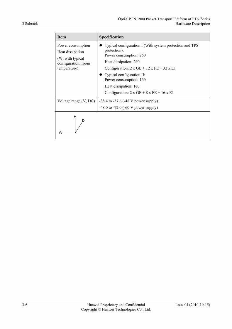
Item Specification
Power consumptionHeat dissipation(W, with typicalconfiguration, roomtemperature)
l Typical configuration I (With system protection and TPSprotection):Power consumption: 260Heat dissipation: 260Configuration: 2 x GE + 12 x FE + 32 x E1
l Typical configuration II:Power consumption: 160Heat dissipation: 160Configuration: 2 x GE + 8 x FE + 16 x E1
Voltage range (V, DC) -38.4 to -57.6 (-48 V power supply)-48.0 to -72.0 (-60 V power supply)
W
HD
3 SubrackOptiX PTN 1900 Packet Transport Platform of PTN Series
Hardware Description
3-6 Huawei Proprietary and ConfidentialCopyright © Huawei Technologies Co., Ltd.
Issue 04 (2010-10-15)

4 Board Overview
About This Chapter
This section describes the appearance, dimension, classification, inter-board relation, andrunning environment of boards.
4.1 Appearance and Dimensions of BoardsAppearance and dimensions vary with types of boards.
4.2 Board ClassificationBoards of the OptiX PTN 1900 include the service sub-board, interface board, system control,cross-connect and multiprotocol processing board, fan board and power supply board.
4.3 Inter-Board RelationBoards for the OptiX PTN 1900 are used together to provide various functions for the equipment.
4.4 Board Running EnvironmentThe equipment should be running in the qualified environment, and thus boards can runnormally.
OptiX PTN 1900 Packet Transport Platform of PTN SeriesHardware Description 4 Board Overview
Issue 04 (2010-10-15) Huawei Proprietary and ConfidentialCopyright © Huawei Technologies Co., Ltd.
4-1

4.1 Appearance and Dimensions of BoardsAppearance and dimensions vary with types of boards.
Table 4-1 provides the appearance and dimensions of boards for the OptiX PTN 1900.
Table 4-1 Appearance and dimensions of boards for the OptiX PTN 1900
Board type Appearance Dimensions (mm)
System control, cross-connect and multiprotocolprocessing board(CXP)
50.8 (width) x 265.3 (depth)x 378.0 (height)
Service sub-board(Such as AD1)
25.4 (width) x 197.1 (depth)x 128.1 (height)
4 Board OverviewOptiX PTN 1900 Packet Transport Platform of PTN Series
Hardware Description
4-2 Huawei Proprietary and ConfidentialCopyright © Huawei Technologies Co., Ltd.
Issue 04 (2010-10-15)

Board type Appearance Dimensions (mm)
Interface board(Such as ETFC)
22.0 (width) x 156.9 (depth)x 264.1 (height)
PIU 55.0 (width) x 157.1 (depth)x 108.6 (height)
OptiX PTN 1900 Packet Transport Platform of PTN SeriesHardware Description 4 Board Overview
Issue 04 (2010-10-15) Huawei Proprietary and ConfidentialCopyright © Huawei Technologies Co., Ltd.
4-3

Board type Appearance Dimensions (mm)
FANA 45.4 (width) x 148.8 (depth)x 111.0 (height)
FANB 44.4 (width) x 258.7 (depth)x 102.6 (height)
NOTE
W
HD
4.2 Board ClassificationBoards of the OptiX PTN 1900 include the service sub-board, interface board, system control,cross-connect and multiprotocol processing board, fan board and power supply board.
Table 4-2 lists the boards of the OptiX PTN 1900 and their functions.
Table 4-2 Boards and their key functions
Board Type Board Name Key Function
Service sub-board MD1, CD1, AD1 Processes E1 signals.Accesses and processeschannelized STM-1 andATM STM-1 signals.
4 Board OverviewOptiX PTN 1900 Packet Transport Platform of PTN Series
Hardware Description
4-4 Huawei Proprietary and ConfidentialCopyright © Huawei Technologies Co., Ltd.
Issue 04 (2010-10-15)

Board Type Board Name Key Function
Interface board ETFC, EFG2, POD41, L12,L75, EFF8, AFO1
Accesses FE, GE, POSSTM-1/STM-4, ATMSTM-1, and E1 signals.
System control, cross-connect and multiprotocolprocessing board
CXP Acts as a service processingboard and processes servicesaccessed.Grooms services accessed.Provides the auxiliaryinterfaces.Performs the system controlfunction.Processes the clock and time.
Fan board FANA, FANB Dissipates heat generated bythe equipment.
Power supply board PIU Accesses the external powersupply.
4.3 Inter-Board RelationBoards for the OptiX PTN 1900 are used together to provide various functions for the equipment.
Figure 4-1 shows the inter-board relation of boards for the OptiX PTN 1900.
OptiX PTN 1900 Packet Transport Platform of PTN SeriesHardware Description 4 Board Overview
Issue 04 (2010-10-15) Huawei Proprietary and ConfidentialCopyright © Huawei Technologies Co., Ltd.
4-5

Figure 4-1 Diagram of the inter-board relation of boards for the OptiX PTN 1900
NNI
ATM STM-1
E1
Channelized STM-1
UNI
Cabinet indicator interface
Alarm interface
NM interface
Control and administration
module
Service processing and
forwardingmodule
Clock module
MD1
AD1
CD1
L75/L12
ETFC
Power supply module
(PIU)
Heat dissipation module
(FANA, FANB)
CXP
FE
-48V/-60V
-48V/-60V
F&f
EFG2GE
MD1 L75/L12
CD1
EFF8FEPOS STM-1/STM-4
E1
GE
Channelized STM-1
EFF8FE
POD41
EFG2
AFO1ATM STM-1
NOTE
On the UNI side, the equipment is connected to the customer edge to access user services to the packetswitching network (PSN).
On the NNI side, the equipment is connected to the PSN equipment to complete the transmission of userservices in the PSN network.
4.4 Board Running EnvironmentThe equipment should be running in the qualified environment, and thus boards can runnormally.
Table 4-3 lists the requirements for the board running environment.
Table 4-3 Requirements for the board running environment
Running Period Ambient Temperature Relative Humidity
Long-time running -5°C to 55°C 5% to 85%
Short-time running 5% to 95%
4 Board OverviewOptiX PTN 1900 Packet Transport Platform of PTN Series
Hardware Description
4-6 Huawei Proprietary and ConfidentialCopyright © Huawei Technologies Co., Ltd.
Issue 04 (2010-10-15)

NOTEShort-time running: the continuous running period not more than 72 hours, and the accumulated running periodof a year not more than 15 days.
OptiX PTN 1900 Packet Transport Platform of PTN SeriesHardware Description 4 Board Overview
Issue 04 (2010-10-15) Huawei Proprietary and ConfidentialCopyright © Huawei Technologies Co., Ltd.
4-7


5 Processing Boards
About This Chapter
For the OptiX PTN 1900, processing boards, such as the MD1, CD1 and AD1, are available.
5.1 MD1This section describes the MD1, a 32 x E1 service sub-board, in terms of the version, function,feature, working principle, front panel, valid slots and technical specifications.
5.2 CD1This section describes the CD1, a 2 x channelized STM-1 sub-board, in terms of the version,function, feature, working principle, front panel, valid slots and technical specifications.
5.3 AD1This section describes the AD1, a 2 x STM-1 ATM sub-board, in terms of the version, function,feature, working principle, front panel, valid slots and technical specifications.
OptiX PTN 1900 Packet Transport Platform of PTN SeriesHardware Description 5 Processing Boards
Issue 04 (2010-10-15) Huawei Proprietary and ConfidentialCopyright © Huawei Technologies Co., Ltd.
5-1

5.1 MD1This section describes the MD1, a 32 x E1 service sub-board, in terms of the version, function,feature, working principle, front panel, valid slots and technical specifications.
5.1.1 Version DescriptionThe function version of the MD1 is TN81.
5.1.2 Functions and FeaturesThe MD1 mainly processes CES E1, IMA E1, ATM E1 and ML-PPP E1 services. The MD1and the CXP form a 32-channel multiprotocol packet E1 processing system.
5.1.3 Working Principle and Signal FlowThe MD1 mainly consists of the line processing module, service converting module, link layerprocessing module, data processing module, logic control module, clock module and powersupply module.
5.1.4 Front PanelOn the front panel of the MD1, there are indicators.
5.1.5 Valid SlotsWhen the MD1 is used as a service sub-board, it should be housed in the sub-slot of the CXP.
5.1.6 TPS Protection for BoardsWhen used with the CXP and interface board, the MD1 can provide two 1:1 TPS protectiongroups.
5.1.7 Board Configuration ReferenceYou can use the U2000 to configure parameters for the MD1.
5.1.8 Technical SpecificationsSpecifications of the MD1 board cover board dimensions, weight and power consumption.
5.1.1 Version DescriptionThe function version of the MD1 is TN81.
5.1.2 Functions and FeaturesThe MD1 mainly processes CES E1, IMA E1, ATM E1 and ML-PPP E1 services. The MD1and the CXP form a 32-channel multiprotocol packet E1 processing system.
Table 5-1 lists the functions and features of the MD1.
Table 5-1 Functions and features of the MD1
Function andFeature
Description
Basic function Used with an interface board, the MD1 can access 32 x E1 services,and works with the CXP and the L12/L75 to process the 32-channelmultiprotocol packet E1 services.
5 Processing BoardsOptiX PTN 1900 Packet Transport Platform of PTN Series
Hardware Description
5-2 Huawei Proprietary and ConfidentialCopyright © Huawei Technologies Co., Ltd.
Issue 04 (2010-10-15)

Function andFeature
Description
The CES, IMA, and ML-PPP protocols can be flexibly configuredbased on the E1 port.Supports the Fractional E1. Supports the CES services and IMAservices at 64 kbit/s level.
Collection of bandwidthutilization statistics at anIMA/ML-PPP port
Supported.
Inband DCN Supported.
Bit error testfunction
Supported. If bit errors occur in a certain period, the board reports analarm.
PRBSa Supports the PRBS function in framed or unframed mode of an E1port in the receive/transmit direction.
IMA Number of supported IMAgroups
32
Maximum number ofsupported E1 links of eachIMA group
32
Dynamically enables/disables IMA groups, restarts the IMA groupprotocol, and dynamically add/delete IMA group members.
Supported traffic type Constant Bit Rate (CBR)Unspecified Bit Rate (UBR)UBR+Real Time Variable Bit Rate (rt-VBR)Non-real Time Variable Bit Rate (nrt-VBR)
Number of supported ATMservices
256
Number of supported ATMVP/VC switchingconnections
1 k
Supports the encapsulation from ATM VPC/VCC to PWE3 in the N-to-1 (N≤32) and 1-to-1 formats.
Supports the PW encapsulation for the ATM cells in the concatenationand non-concatenation formats. The number of PW connections thatsupport the cell concatenation is 256, and the maximum number ofconcatenated cells is 31.
UNI-side ATM OAM Supports the connection confirm (CC)test.
OptiX PTN 1900 Packet Transport Platform of PTN SeriesHardware Description 5 Processing Boards
Issue 04 (2010-10-15) Huawei Proprietary and ConfidentialCopyright © Huawei Technologies Co., Ltd.
5-3

Function andFeature
Description
Supports the loopback (LB) test.
Supports the AIS.
Supports the RDI.
CES Number of supported CESservices
32
Supported emulation mode CESoPSNSAToP
Supports the timeslot suppression function. Provides the idle 64 kbit/s timeslot suppression function for the CES services in the CESoPSNmode to save the transmission bandwidth.
Supported clock mode RetimingSelf-adaptation
Supports setting of the jitter compensation buffer time for the CESservice. (Range: 0.375 ms to 64 ms; step: 0.125 ms)
Supports setting of the packet loading time for the CES service.(Range: 0.125 ms to 3 ms; step: 0.125 ms)
ML-PPP Supported number of ML-PPP groups.
32
Maximum number ofsupported links in each ML-PPP group.
16
Used as the NNI.
APS for ML-PPPlinks
APS 1+1 and 1:1 protection and APS 1+1 protection can be configuredfor the LSPs carried by ML-PPP links.
TPS protection Supports the TPS protection.
Clock Work with the interface boards to process the line clocks.
a: The PRBS test function and the port loopback function can not be enabled at the same time.
5.1.3 Working Principle and Signal FlowThe MD1 mainly consists of the line processing module, service converting module, link layerprocessing module, data processing module, logic control module, clock module and powersupply module.
Figure 5-1 shows the block diagram for the working principle of the MD1.
5 Processing BoardsOptiX PTN 1900 Packet Transport Platform of PTN Series
Hardware Description
5-4 Huawei Proprietary and ConfidentialCopyright © Huawei Technologies Co., Ltd.
Issue 04 (2010-10-15)

Figure 5-1 Block diagram for the working principle of the MD1
Line processing module
Link layer processing
module
Data processing module
32 x E1Interface boards
Service signals
CXPManagement
module
Power supply module
3.3V
1.2V
.
.
.
.
.
.
Management bus
Clock module
Management busManagement busManagement bus
Service signals
Service signals
In the Transmit DirectionThe MD1 first distributes packets, sent by the CXP, to different protocol processing modulesby the service type. For data processing module, decapsulation should be performed. The ingressqueue is then buffered and the egress queue is groomed by the service type. Then packets aresent to the link layer processing module. The line processing module performs encoding, de-jitter, pulse shaping and line driving for the services, which are finally sent to the interface board.
In the Receive DirectionThe interface board accesses E1 signals. The line processing module then performs impedancematch, signal equalization, electrical level conversion, clock data recovery, de-jitter anddecoding for the E1 signals. The link layer processing module and data processing moduleperform encapsulation and mapping of IMA E1, CES E1 and ML-PPP E1 services to PWE3. Inaddition, PW grooming is performed. Finally, the E1 services are sent to the CXP in the Ethernetpacket format.
Line Processing ModuleIn the receive channels, impedance match, signal equalization, electrical level conversion, clockdata recovery, de-jitter and decoding are performed to signals. In the transmit channels,encoding, de-jitter, pulse shaping and line driving are performed to signals.
Link Layer Processing ModuleThis module supports three protocol types, that is, IMA, CES and ML-PPP. The TDM circuitswitching, ATM cell switching can be performed on a uniform hardware platform.
Data Processing ModuleThis module performs encapsulation or decapsulation of IMA, CES and ML-PPP services to orfrom PWE3. In this way, data can be forwarded from the PPP to the MPLS. In addition, thismodule buffers the upstream and downstream packets, and grooms services.
Management ModuleThis module manages and controls the modules on the board.
OptiX PTN 1900 Packet Transport Platform of PTN SeriesHardware Description 5 Processing Boards
Issue 04 (2010-10-15) Huawei Proprietary and ConfidentialCopyright © Huawei Technologies Co., Ltd.
5-5

Clock ModuleThis module works with the CXP to process the line clock.
Power Supply ModuleThis module converts the voltage sent by the CXP to DC voltages required by each module onthe MD1.
5.1.4 Front PanelOn the front panel of the MD1, there are indicators.
Appearance of the Front PanelFigure 5-2 shows the appearance of the front panel of the MD1.
Figure 5-2 Appearance of the front panel of the MD1
IndicatorThe following indicators are present on the front panel of the MD1.
l STAT indicator, red, green, or orange, which indicates the working statusl ACT indicator, green, which indicates the service activation statusl SRV indicator, red, green, or orange, which indicates the service status
For details on indications of indicators, see A.2 Board Indicators.
5.1.5 Valid SlotsWhen the MD1 is used as a service sub-board, it should be housed in the sub-slot of the CXP.
5 Processing BoardsOptiX PTN 1900 Packet Transport Platform of PTN Series
Hardware Description
5-6 Huawei Proprietary and ConfidentialCopyright © Huawei Technologies Co., Ltd.
Issue 04 (2010-10-15)

Table 5-2 lists the mapping relation between slots for the CXP that houses the MD1 and slotsfor the corresponding interface board.
Table 5-2 Mapping relation between slots for the CXP that houses the MD1 and slots for thecorresponding interface board
Slot for the CXP That Houses the MD1 Slot for the Interface Board
Slot 1-1 Slots 3, 4
Slot 1-2 Slots 5, 6
Slot 2-1 Slots 3, 4
Slot 2-2 Slots 5, 6
CAUTIONWhen used as the active sub-board, the MD1 can be housed only in sub-slot 1-1 and sub-slot1-2.
5.1.6 TPS Protection for BoardsWhen used with the CXP and interface board, the MD1 can provide two 1:1 TPS protectiongroups.
NOTE
The interface boards for the MD1 are L75 and L12. The two interface boards can realize the TPS protectionwhen used with the MD1 and CXP. In addition, the protection principles and hardware configuration modesare the same. The TPS protection described in this document considers the L75 as an example.
Protection PrincipleFigure 5-3 shows the TPS protection principle of the MD1.
OptiX PTN 1900 Packet Transport Platform of PTN SeriesHardware Description 5 Processing Boards
Issue 04 (2010-10-15) Huawei Proprietary and ConfidentialCopyright © Huawei Technologies Co., Ltd.
5-7

Figure 5-3 TPS protection principle of the service sub-board MD1
TPS switching control bus
32 x E1
L75
21
L75
21
Protection boardWorking board
MD1
CXP CXP
FailureMD1
When the CXP detects that a working MD1 is faulty, the CXP performs the protection switchingby using the TPS control bus to trigger the switch on the interface board. After the switching,the services accessed by the interface board are switched to the protection board for processing.Thus, the protection is realized.
Hardware ConfigurationThe MD1 is a service sub-board, which should be housed in the sub-slot of the CXP. When usedwith the CXP and interface board, the MD1 can provide two 1:1 TPS protection groups. Figure5-4 shows the hardware configuration.
Figure 5-4 Hardware configuration of two 1:1 TPS protection groups provided by the servicesub-board MD1
SLOT 8 PIU
SLOT 9 PIUSLOT 7
SLOT10
(FANA)
SLOT11
(FANB)
SLOT 1
SLOT 2
SLOT 1-1CXP
MD1
CXP
SLOT 1-2
SLOT 2-2SLOT 2-1 MD1 MD1
MD1
SLOT 3SLOT 4SLOT 5SLOT 6
L75L75L75L75
5 Processing BoardsOptiX PTN 1900 Packet Transport Platform of PTN Series
Hardware Description
5-8 Huawei Proprietary and ConfidentialCopyright © Huawei Technologies Co., Ltd.
Issue 04 (2010-10-15)

NOTE
In the figure, each CXP houses a service sub-board MD1. The two TPS protection groups are of the 1:1protection. The board housed in slot 2-1 protects the board housed in slots 1-1. The board housed in slot2-2 protects the board housed in slots 1-2.
Table 5-3 shows the mapping relation between slots for the working boards and slots for theprotection boards of the TPS protection.
Table 5-3 Mapping relation between slots for the working boards and slots for the protectionboards of the TPS protection for the service sub-board MD1
Slot for the WorkingBoard
Slot for the ProtectionBoard
Slot for the InterfaceBoard
Slot 1-1 Slot 2-1 Slots 3, 4
Slot 1-2 Slot 2-2 Slots 5, 6
5.1.7 Board Configuration ReferenceYou can use the U2000 to configure parameters for the MD1.
You can use the U2000 to configure the following parameters for the MD1.
l Spare timeslot recovery value
For details on the parameters, see D Board Configuration Parameters.
5.1.8 Technical SpecificationsSpecifications of the MD1 board cover board dimensions, weight and power consumption.
Board dimensions (mm): 128.1 (H) x 197.1 (D) x 25.4 (W)
Weight (kg): 0.34
Power consumption (W): 20.7
5.2 CD1This section describes the CD1, a 2 x channelized STM-1 sub-board, in terms of the version,function, feature, working principle, front panel, valid slots and technical specifications.
5.2.1 Version DescriptionThe function version of the CD1 is TN81.
5.2.2 Functions and FeaturesWhen used with the CXP, the CD1 processes channelized STM-1 services. The CD1 can mappacket E1 data into VC-12 for transmission. The CES, IMA, ATM E1 and ML-PPP E1 can bebundled for transmission.
5.2.3 Working Principle and Signal Flow
OptiX PTN 1900 Packet Transport Platform of PTN SeriesHardware Description 5 Processing Boards
Issue 04 (2010-10-15) Huawei Proprietary and ConfidentialCopyright © Huawei Technologies Co., Ltd.
5-9

The CD1 mainly consists of the SDH processing module, link layer processing module, dataprocessing module, management module, clock module and power supply module.
5.2.4 Front PanelOn the front panel of the CD1, there are indicators, a laser safety class label and interfaces.
5.2.5 Valid SlotsThe CD1, which is a service sub-board, should be housed in the sub-slot of the CXP.
5.2.6 Board Configuration ReferenceYou can use the U2000 to configure parameters for the CD1.
5.2.7 Technical SpecificationsSpecifications of the CD1 board cover specifications of interfaces, board dimensions, weightand power consumption.
5.2.1 Version DescriptionThe function version of the CD1 is TN81.
5.2.2 Functions and FeaturesWhen used with the CXP, the CD1 processes channelized STM-1 services. The CD1 can mappacket E1 data into VC-12 for transmission. The CES, IMA, ATM E1 and ML-PPP E1 can bebundled for transmission.
Table 5-4 lists the functions and features of the CD1.
Table 5-4 Functions and features of the CD1
Function andFeature
Description
Basic function Supports two channelized STM-1 optical interfaces on the front panel.Supports the Fractional E1. Supports the CES services and IMAservices at 64 kibt/s level.Supports collection of bandwidth utilization statistics at an IMA/ML-PPP port.
Interface function Automatic shutdown of thelaser at the port
Supported.
Type of the loopback at theport
Inloop at an STM-1 portOutloop at an STM-1 portInloop in a VC-12 channelOutloop in a VC-12 channel
Automatic releasing of theloopback at the port
Supported.
5 Processing BoardsOptiX PTN 1900 Packet Transport Platform of PTN Series
Hardware Description
5-10 Huawei Proprietary and ConfidentialCopyright © Huawei Technologies Co., Ltd.
Issue 04 (2010-10-15)

Function andFeature
Description
All VC-12 timeslots of each CD1 optical interface support the DCNfunction. By default, only the first, seventeenth, thirty-third, and forty-ninth channels of VC-12 timeslots of each optical interface supportthe DCN function.Manually enabling or disabling the DCN function of VC-12 timeslotsof CD1 optical interface is supported.
PRBSa Supports the PRBS function in framed or unframed mode of a VC-12channel in the receive/transmit direction.
IMA Number of supported IMAgroups
126
Maximum number ofsupported VC-12 timeslotsof each IMA group
32
Dynamically enables/disables IMA groups, restarts the IMA groupprotocol, and dynamically add/delete IMA group members.
Supported traffic type CBRUBRUBR+rt-VBRnrt-VBR
Number of supported ATMservices
256 (128 supported by each opticalinterface)
Number of supported ATMVP/VC switchingconnections
1 k (512 supported by each opticalinterface)
Supports the encapsulation from ATM VPC/VCC to PWE3 in the N-to-1 (N≤32) and 1-to-1 formats.
Supports the PW encapsulation for the ATM cells in the concatenationand non-concatenation formats. The number of PW connections thatsupport the cell concatenation is 256, and the maximum number ofconcatenated cells is 31.
UNI-side ATM OAM Supports the CC test.
Supports the LB test.
Supports the AIS.
Supports the RDI.
CES Number of supported CESservices
126
OptiX PTN 1900 Packet Transport Platform of PTN SeriesHardware Description 5 Processing Boards
Issue 04 (2010-10-15) Huawei Proprietary and ConfidentialCopyright © Huawei Technologies Co., Ltd.
5-11

Function andFeature
Description
Supported emulation mode CESoPSNSAToP
Supports the timeslot suppression function. Provides the idle 64 kbit/s timeslot suppression function for the CES services in the CESoPSNmode to save the transmission bandwidth.
Supported clock mode RetimingSelf-adaptation
Supports setting of the jitter compensation buffer time for the CESservice. (Range: 0.375 ms to 64 ms; step: 0.125 ms)
Supports setting of the packet loading time for the CES service.(Range: 0.125 ms to 3 ms; step: 0.125 ms)
ML-PPP Supported number of ML-PPP groups.
64
Maximum number ofsupported links in each ML-PPP group.
16
Used as the NNI.
Extraction andinsertion of S1 bytes
Supported.
LMSP protection Supports the 1+1 LMSP and 1:1 LMSP protection.
a: The PRBS test function and the port loopback function can not be enabled at the same time.
5.2.3 Working Principle and Signal FlowThe CD1 mainly consists of the SDH processing module, link layer processing module, dataprocessing module, management module, clock module and power supply module.
Figure 5-5 shows the block diagram for the working principle of the CD1.
Figure 5-5 Block diagram for the working principle of the CD1
SDH processing
module
Link layer processing
module
Data processing
module
Channelized STM-1
CXPManagement
module
Power supply module
3.3V
1.2V
.
.
.
.
.
.
Management bus
Clock module
Service signals Service signalsService signals
Management bus Management busManagement bus
5 Processing BoardsOptiX PTN 1900 Packet Transport Platform of PTN Series
Hardware Description
5-12 Huawei Proprietary and ConfidentialCopyright © Huawei Technologies Co., Ltd.
Issue 04 (2010-10-15)

In the Transmit DirectionThe CD1 first distributes signals, sent by the CXP, to different protocol processing modulesaccording to the service type. These chips then decapsulate these signals. The data processingmodule buffers the ingress queues and grooms the egress queues according to the service type.The data processing module then sends the packets to the link layer processing module. The linklayer processing module processes the packets according to different protocols, and then framesthe processed signals and sends the signals to the SDH processing module, which adds overheadto the signals and multiplexes the signals to STM-1 signals.
In the Receive DirectionThe SDH processing module first processes overhead of the channelized STM-1 signals that areaccessed, and demultiplexes the signals to E1 signals. The SDH processing module sends theE1 signals to the link layer processing module, which frames the E1 signals and processes theframed signals according to the different protocols. The processed signals are then sent to thedata processing module. The data processing module performs PWE3 encapsulation for IMA,CES and ML-PPP services, and grooms the PW connections. Finally, the data processing modulesends the packets to the CXP.
SDH Processing ModuleIn the transmit direction, this module adds overhead to the signals and multiplexes the E1 signalsto STM-1 signals. In the receive direction, this module processes overhead of the STM-1 signals,and demultiplexes the channelized STM-1 signals into E1 signals.
Link Layer Processing ModuleThis module frames E1 siganals, and supports three protocol types, that is, IMA, CES and ML-PPP. The TDM circuit switching, ATM cell switching can be performed on a uniform hardwareplatform.
Data Processing ModuleThis module performs PWE3 encapsulation and decapsulation for IMA, CES and ML-PPPmultiple services, and forwards data according to the MPLS tags in the PPP packets. In addition,this module buffers the upstream and downstream packets, and grooms services.
Management ModuleThis module manages and controls the modules on the board.
Clock ModuleThis module works with the CXP to process the line clock.
Power Supply ModuleThis module converts the voltage, sent by the CXP, to DC voltages required by each module onthe CD1.
OptiX PTN 1900 Packet Transport Platform of PTN SeriesHardware Description 5 Processing Boards
Issue 04 (2010-10-15) Huawei Proprietary and ConfidentialCopyright © Huawei Technologies Co., Ltd.
5-13
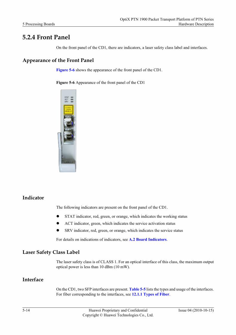
5.2.4 Front PanelOn the front panel of the CD1, there are indicators, a laser safety class label and interfaces.
Appearance of the Front Panel
Figure 5-6 shows the appearance of the front panel of the CD1.
Figure 5-6 Appearance of the front panel of the CD1
Indicator
The following indicators are present on the front panel of the CD1.
l STAT indicator, red, green, or orange, which indicates the working status
l ACT indicator, green, which indicates the service activation status
l SRV indicator, red, green, or orange, which indicates the service status
For details on indications of indicators, see A.2 Board Indicators.
Laser Safety Class Label
The laser safety class is of CLASS 1. For an optical interface of this class, the maximum outputoptical power is less than 10 dBm (10 mW).
Interface
On the CD1, two SFP interfaces are present. Table 5-5 lists the types and usage of the interfaces.For fiber corresponding to the interfaces, see 12.1.1 Types of Fiber.
5 Processing BoardsOptiX PTN 1900 Packet Transport Platform of PTN Series
Hardware Description
5-14 Huawei Proprietary and ConfidentialCopyright © Huawei Technologies Co., Ltd.
Issue 04 (2010-10-15)

Table 5-5 Types and usage of the interfaces on the CD1
Interface onthe FrontPanel
InterfaceType
Usage
IN1 - IN2 LC When a two-fiber bidirectional optical module is used, this interface is used asan input interface for the STM-1 optical signal.When a single-fiber bidirectional optical module is used, this interface is notused.
OUT1 - OUT2 LC When a two-fiber bidirectional optical module is used, this interface is used asan output interface for the STM-1 optical signal.When a single-fiber bidirectional optical module is used, this interface is usedas an input/output interface for the STM-1 optical signal.
NOTEThe SFP interface should be used with an optical module.
l When a two-fiber bidirectional optical module is used, two LC interfaces are provided on the left and right sides of the opticalmodule. Each interface uses one fiber, which is used to transmit or receive service signals.
l When a single-fiber bidirectional optical module is used, only one LC interface is provided on the left side of the opticalmodule. This optical interface uses only one fiber, which is used to transmit and receive service signals at the same time.
5.2.5 Valid SlotsThe CD1, which is a service sub-board, should be housed in the sub-slot of the CXP.
5.2.6 Board Configuration ReferenceYou can use the U2000 to configure parameters for the CD1.
You can use the U2000 to configure the following parameters for the CD1.
l Automatic Laser Shutdownl J0l J1l J2l C2l V5l SDH Interfacel Path Configurationl Spare Timeslot Recovery Value
For details on the parameters, see D Board Configuration Parameters.
5.2.7 Technical SpecificationsSpecifications of the CD1 board cover specifications of interfaces, board dimensions, weightand power consumption.
Table 5-6 lists the specifications of interfaces on the CD1.
OptiX PTN 1900 Packet Transport Platform of PTN SeriesHardware Description 5 Processing Boards
Issue 04 (2010-10-15) Huawei Proprietary and ConfidentialCopyright © Huawei Technologies Co., Ltd.
5-15

Table 5-6 Technical specifications of the STM-1 optical interface
Item Specification
Nominal bit rate(kbit/s)
155520
Optical interfacetype
Two-fiber bidirectional interface Single-fiber bidirectional interface
S-1.1(15 km)
L-1.1(40 km)
L-1.2(80 km)
S-1.1(10 km)
L-1.1(40 km)
Fiber type Single-mode Single-mode Single-mode Single-mode Single-mode
Workingwavelengthrange (nm)
1261 to 1360 1263 to 1360 1480 to 1580 For details, seethe followingtable, relatedoptical modulepart numbers ofsingle-fiberbidirectionaloptical interfaceand wavelengthallocation.
For details, seethe followingtable, relatedoptical modulepart numbers ofsingle-fiberbidirectionaloptical interfaceand wavelengthallocation.
Mean launchedoptical power(dBm)
-15 to -8 -5 to 0 -5 to 0 -15 to -8 -5 to 0
Receiversensitivity(dBm)
-28 -34 -34 -28.2 -30
Minimumoverload (dBm)
-8 -10 -10 -8 -10
Minimumextinction ratio(dB)
8.2 10 10 6.6 10
Optical modulepart number
34060276 34060281 34060282 For details, seethe followingtable, relatedoptical modulepart numbers ofsingle-fiberbidirectionaloptical interfaceand wavelengthallocation.
For details, seethe followingtable, relatedoptical modulepart number ofsingle-fiberbidirectionaloptical interfaceand wavelengthallocation.
NOTEFor details of the optical module, see 10.2 Optical Module Labels.
5 Processing BoardsOptiX PTN 1900 Packet Transport Platform of PTN Series
Hardware Description
5-16 Huawei Proprietary and ConfidentialCopyright © Huawei Technologies Co., Ltd.
Issue 04 (2010-10-15)
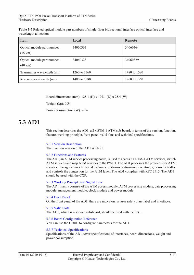
Table 5-7 Related optical module part numbers of single-fiber bidirectional interface optical interface andwavelength allocation
Item Local Remote
Optical module part number(15 km)
34060363 34060364
Optical module part number(40 km)
34060328 34060329
Transmitter wavelength (nm) 1260 to 1360 1480 to 1580
Receiver wavelength (nm) 1480 to 1580 1260 to 1360
Board dimensions (mm): 128.1 (H) x 197.1 (D) x 25.4 (W)
Weight (kg): 0.34
Power consumption (W): 26.4
5.3 AD1This section describes the AD1, a 2 x STM-1 ATM sub-board, in terms of the version, function,feature, working principle, front panel, valid slots and technical specifications.
5.3.1 Version DescriptionThe function version of the AD1 is TN81.
5.3.2 Functions and FeaturesThe AD1, an ATM service processing board, is used to access 2 x STM-1 ATM services, switchATM services and map ATM services to the PWE3. The AD1 processes the protocols for ATMservices, manages connections and resources, performs performance counting, grooms the trafficand controls the congestion for the ATM layer. The AD1 complies with RFC 2515. The AD1should be used with the CXP.
5.3.3 Working Principle and Signal FlowThe AD1 mainly consists of the ATM access module, ATM processing module, data processingmodule, management module, clock module and power module.
5.3.4 Front PanelOn the front panel of the AD1, there are indicators, a laser safety class label and interfaces.
5.3.5 Valid SlotsThe AD1, which is a service sub-board, should be used with the CXP.
5.3.6 Board Configuration ReferenceYou can use the U2000 to configure parameters for the AD1.
5.3.7 Technical SpecificationsSpecifications of the AD1 cover specifications of interfaces, board dimensions, weight andpower consumption.
OptiX PTN 1900 Packet Transport Platform of PTN SeriesHardware Description 5 Processing Boards
Issue 04 (2010-10-15) Huawei Proprietary and ConfidentialCopyright © Huawei Technologies Co., Ltd.
5-17

5.3.1 Version DescriptionThe function version of the AD1 is TN81.
5.3.2 Functions and FeaturesThe AD1, an ATM service processing board, is used to access 2 x STM-1 ATM services, switchATM services and map ATM services to the PWE3. The AD1 processes the protocols for ATMservices, manages connections and resources, performs performance counting, grooms the trafficand controls the congestion for the ATM layer. The AD1 complies with RFC 2515. The AD1should be used with the CXP.
Table 5-8 lists the functions and features of the AD1.
Table 5-8 Functions and Features of the AD1
Function andFeature
Description
Basic function Service interface on thefront panel
Two ATM STM-1 optical interfaces.
Interface function Automatic shutdown of thelaser at the port
Supported.
Type of the loopback at theport
InloopOutloop
Automatic releasing of theloopback at the port
Supported.
ATM Supported traffic type CBRUBRUBR+rt-VBRnrt-VBR
Number of supported ATMservices
1 k (512 supported by each opticalinterface)
Number of supported ATMVP/VC switchingconnections
2 k (1 k supported by each opticalinterface)
Supports the encapsulation from ATM VPC/VCC to PWE3 in the N-to-1 (N≤32) and 1-to-1 formats.
Supports the PW encapsulation for the ATM cells in the concatenationand non-concatenation formats. The number of PW connections thatsupport the cell concatenation is 512, and the maximum number ofconcatenated cells is 31.
UNI-side ATM OAM Supports the CC test.
Supports the LB test.
5 Processing BoardsOptiX PTN 1900 Packet Transport Platform of PTN Series
Hardware Description
5-18 Huawei Proprietary and ConfidentialCopyright © Huawei Technologies Co., Ltd.
Issue 04 (2010-10-15)

Function andFeature
Description
Supports the AIS.
Supports the RDI.
LMSP protection Supports the 1+1 LMSP and 1:1 LMSP protection. The protectionswitching time is less than 50 ms.
Extraction andinsertion of S1 bytes
Supported.
5.3.3 Working Principle and Signal FlowThe AD1 mainly consists of the ATM access module, ATM processing module, data processingmodule, management module, clock module and power module.
Figure 5-7 shows the block diagram for the working principle of the AD1.
Figure 5-7 Block diagram for the working principle of the AD1
ATM access module
ATM processing
module
Data processing
module
ATM STM-1Service signals
Service signals
Service signals
CXPManagement module
Power supply module
3.3V
1.2V
.
.
.
.
.
.
Management bus
Management bus Management busManagement bus
Clock module
In the Transmit DirectionThe CXP sends packets to the data processing module, which demaps the PWE3 to ATM servicesand switches the ATM services. The data processing module then sends the ATM services tothe ATM lprocessing module. The ATM processing module processes the protocols for ATMservices, manages connections and resources, performs performance counting, grooms the trafficand controls the congestion for the ATM layer. The ATM processing module then sends theservices to the ATM access module. In the ATM access module, ATM services are mapped intoSDH services, which become STM-1 ATM optical signals after converted from electrical signalsto optical signals.
In the Receive DirectionFirst, 2 x STM-1 ATM optical signals are converted to electrical signals and sent to the ATMaccess module. This module extracts ATM cells from the SDH services and sends the ATM cellsto the ATM layer processing module. The ATM processing module then processes the protocols
OptiX PTN 1900 Packet Transport Platform of PTN SeriesHardware Description 5 Processing Boards
Issue 04 (2010-10-15) Huawei Proprietary and ConfidentialCopyright © Huawei Technologies Co., Ltd.
5-19

for ATM services, manages connections and resources, performs performance counting, groomsthe traffic and controls the congestion for the ATM layer. The services are then sent to the dataprocessing module. The data processing module switches the ATM services and maps the ATMservices to the PWE3. Finally, services are sent to the CXP.
ATM Access Module
This module performs the following functions:
l In the upstream direction, the SDH overheads, alarms, and pointers are processed on theaccessed ATM STM-1 signals. The ATM cells are extracted from the SDH signals, andthen the ATM cells are sent to the ATM processing module, where the line clock isextracted.
l In the downstream direction, the ATM cells from the ATM processing module are mappedto the SDH signals, and then the SDH overhead processing, alarm processing, and pointerprocessing are performed on the signals. In this manner, the SDH frames are formed.
ATM Processing Module
This module mainly realizes the VP/VC switching, QoS functions such as traffic management,traffic shaping, queue scheduling, and OAM function for the ATM cells.
l In the upstream direction, this module determines the traffic priority of the ATM cells. Ifcongestion occurs, this module determines whether to discard the cells or to continuetransmitting cells according to the traffic priority. If the cells are continued to be transmitted,the VP/VC switching is performed on the cells, which are then sent to the data processingmodule.
l In the downstream direction, this module processes the cell packet headers, and performsthe VP/VC switching on the cells. If congestion occurs, this module determines whetherto discard the cells or to continue transmitting cells according to the traffic priority. If thecells are continued to be transmitted, they are sent to the ATM access module.
l Supports the ATM OAM functions:
– Supports the CC test.
– Supports the LB test.
Data Processing Module
This module performs the following functions.
l Encapsulates or decapsulate ATM cells to or from the PWE3.
l Concatenates or deconcatenate ATM cells to or from the PWE3.
Management Module
This module manages and controls the modules on the board.
Clock Module
This module works with the CXP to process the line clock.
5 Processing BoardsOptiX PTN 1900 Packet Transport Platform of PTN Series
Hardware Description
5-20 Huawei Proprietary and ConfidentialCopyright © Huawei Technologies Co., Ltd.
Issue 04 (2010-10-15)

Power Supply ModuleThis module converts the voltage, sent by the CXP, to DC voltages required by each module onthe AD1.
5.3.4 Front PanelOn the front panel of the AD1, there are indicators, a laser safety class label and interfaces.
Appearance of the Front PanelFigure 5-8 shows the appearance of the front panel of the AD1.
Figure 5-8 Appearance of the front panel of the AD1
IndicatorThe following indicators are present on the front panel of the AD1.
l STAT indicator, red, green or orange, which indicates the board statel ACT indicator, green, which indicates that the service is activatedl SRV indicator, red, green or orange, which indicates service alarms
For details on indications of indicators, see A.2 Board Indicators.
Laser Safety Class LabelThe laser safety class is of CLASS 1. For an optical interface of this class, the maximum outputoptical power is less than 10 dBm (10 mW).
InterfaceOn the AD1, two SFP interfaces are present. Table 5-9 lists the types and usage of the interfaces.For fiber corresponding to the interfaces, see 12.1.1 Types of Fiber.
OptiX PTN 1900 Packet Transport Platform of PTN SeriesHardware Description 5 Processing Boards
Issue 04 (2010-10-15) Huawei Proprietary and ConfidentialCopyright © Huawei Technologies Co., Ltd.
5-21

Table 5-9 Types and usage of the interfaces on the AD1
Interface onthe FrontPanel
InterfaceType
Usage
IN1-IN2 LC When a two-fiber bidirectional optical module is used, this interface is usedas an input interface for the STM-1 optical signal.When a single-fiber bidirectional optical module is used, this interface is notused.
OUT1-OUT2 LC When a two-fiber bidirectional optical module is used, this interface is usedas an output interface for the STM-1 optical signal.When a single-fiber bidirectional optical module is used, this interface is usedas an input/output interface for the STM-1 optical signal.
NOTEThe SFP interface should be used with an optical module.
l When a two-fiber bidirectional optical module is used, two LC interfaces are provided on the left and right sides of the opticalmodule. Each interface uses one fiber, which is used to transmit or receive service signals.
l When a single-fiber bidirectional optical module is used, only one LC interface is provided on the left side of the opticalmodule. This optical interface uses only one fiber, which is used to transmit and receive service signals at the same time.
5.3.5 Valid SlotsThe AD1, which is a service sub-board, should be used with the CXP.
5.3.6 Board Configuration ReferenceYou can use the U2000 to configure parameters for the AD1.
You can use the U2000 to configure the following parameters for the AD1.
l Automatic Laser Shutdownl J0l J1l C2l SDH Interface
For details on the parameters, see D Board Configuration Parameters.
5.3.7 Technical SpecificationsSpecifications of the AD1 cover specifications of interfaces, board dimensions, weight andpower consumption.
Table 5-10 lists the specifications of interfaces on the AD1.
5 Processing BoardsOptiX PTN 1900 Packet Transport Platform of PTN Series
Hardware Description
5-22 Huawei Proprietary and ConfidentialCopyright © Huawei Technologies Co., Ltd.
Issue 04 (2010-10-15)

Table 5-10 Technical specifications of the STM-1 optical interface
Item Specification
Nominal bit rate(kbit/s)
155520
Optical interfacetype
Two-fiber bidirectional interface Single-fiber bidirectional interface
S-1.1(15 km)
L-1.1(40 km)
L-1.2(80 km)
S-1.1(10 km)
L-1.1(40 km)
Fiber type Single-mode Single-mode Single-mode Single-mode Single-mode
Workingwavelengthrange (nm)
1261 to 1360 1263 to 1360 1480 to 1580 For details, seethe followingtable, relatedoptical modulepart numbers ofsingle-fiberbidirectionaloptical interfaceand wavelengthallocation.
For details, seethe followingtable, relatedoptical modulepart numbers ofsingle-fiberbidirectionaloptical interfaceand wavelengthallocation.
Mean launchedoptical power(dBm)
-15 to -8 -5 to 0 -5 to 0 -15 to -8 -5 to 0
Receiversensitivity(dBm)
-28 -34 -34 -28.2 -30
Minimumoverload (dBm)
-8 -10 -10 -8 -10
Minimumextinction ratio(dB)
8.2 10 10 6.6 10
Optical modulepart number
34060276 34060281 34060282 For details, seethe followingtable, relatedoptical modulepart numbers ofsingle-fiberbidirectionaloptical interfaceand wavelengthallocation.
For details, seethe followingtable, relatedoptical modulepart number ofsingle-fiberbidirectionaloptical interfaceand wavelengthallocation.
NOTEFor details of the optical module, see 10.2 Optical Module Labels.
OptiX PTN 1900 Packet Transport Platform of PTN SeriesHardware Description 5 Processing Boards
Issue 04 (2010-10-15) Huawei Proprietary and ConfidentialCopyright © Huawei Technologies Co., Ltd.
5-23

Table 5-11 Related optical module part numbers of single-fiber bidirectional interface optical interface andwavelength allocation
Item Local Remote
Optical module part number(15 km)
34060363 34060364
Optical module part number(40 km)
34060328 34060329
Transmitter wavelength (nm) 1260 to 1360 1480 to 1580
Receiver wavelength (nm) 1480 to 1580 1260 to 1360
Board dimensions (mm): 128.1 (H) x 197.1 (D) x 25.4 (W)
Weight (kg): 0.35
Power consumption (W): 22.0
5 Processing BoardsOptiX PTN 1900 Packet Transport Platform of PTN Series
Hardware Description
5-24 Huawei Proprietary and ConfidentialCopyright © Huawei Technologies Co., Ltd.
Issue 04 (2010-10-15)

6 Interface Boards
About This Chapter
Interface boards are mainly used to connect to cables and fibers. This chapter describes theinterface boards for the OptiX PTN 1900, in terms of the version, function, working principle,front panel, and parameters.
6.1 ETFCThis section describes the ETFC, a 12 x FE electrical interface board, in terms of the version,function, feature, working principle, front panel, valid slots and technical specifications.
6.2 EFF8This section describes the EFF8, which is an 8 x FE optical interface board, with regard to theversion, functions, features, working principle, front panel, valid slots, and technicalspecifications.
6.3 EFG2This section describes the EFG2, a 2 x GE optical interface board, in terms of the version,function, feature, working principle, front panel, valid slots and technical specifications.
6.4 POD41This section describes the POD41, a 2 x 622M/155M POS interface board, in terms of theversion, function, feature, working principle, front panel, valid slots and technical specifications.
6.5 AFO1This section describes the AFO1, an 8-channel ATM STM-1 service interface board, in termsof the version, function, feature, working principle, front panel, valid slots, and technicalspecifications.
6.6 L75/L12This section describes the L75/L12, a 16 x E1 75-ohm interface board, in terms of the version,function, feature, working principle, front panel, valid slots and technical specifications.
OptiX PTN 1900 Packet Transport Platform of PTN SeriesHardware Description 6 Interface Boards
Issue 04 (2010-10-15) Huawei Proprietary and ConfidentialCopyright © Huawei Technologies Co., Ltd.
6-1

6.1 ETFCThis section describes the ETFC, a 12 x FE electrical interface board, in terms of the version,function, feature, working principle, front panel, valid slots and technical specifications.
6.1.1 Version DescriptionThe function version of the ETFC is TN81.
6.1.2 Functions and FeaturesThe ETFC accesses 12 x FE electrical signals, and processes the services with the processingboard CXP.
6.1.3 Working Principle and Signal FlowThe ETFC mainly consists of interface conversion module, service processing module,management module, clock module and power supply module.
6.1.4 Front PanelOn the front panel of the ETFC, there are indicators and interfaces.
6.1.5 Valid SlotsFor the OptiX PTN 1900, the ETFC can be housed in any of slots 3 - 7 in the interface area.When used with the active and standby CXP, the ETFC can access and process services fromthe Ethernet electrical interface.
6.1.6 Board Configuration ReferenceYou can use the U2000 to configure parameters for the ETFC.
6.1.7 Technical SpecificationsSpecifications of the ETFC board cover the interface specifications, board dimensions, weightand power consumption.
6.1.1 Version DescriptionThe function version of the ETFC is TN81.
6.1.2 Functions and FeaturesThe ETFC accesses 12 x FE electrical signals, and processes the services with the processingboard CXP.
Table 6-1 lists the functions and features of the ETFC.
Table 6-1 Functions and Features of the ETFC
Function and Feature Description
Basic function Service interface on the frontpanel
12 FE electrical interfaces
Interface function Type of the loopback at theport
PHY layer inloopMAC layer inloop
Automatic releasing of theloopback at the port
Supported.
6 Interface BoardsOptiX PTN 1900 Packet Transport Platform of PTN Series
Hardware Description
6-2 Huawei Proprietary and ConfidentialCopyright © Huawei Technologies Co., Ltd.
Issue 04 (2010-10-15)

Function and Feature Description
Port bandwidth utilizationstatistics
Supported.
Supports the inband DCN, which can be manually enabledand disabled. The DCN function is enabled for the first fourports by default.
LAG Inter-board Supported.
Intra-board Supported.
6.1.3 Working Principle and Signal FlowThe ETFC mainly consists of interface conversion module, service processing module,management module, clock module and power supply module.
Figure 6-1 shows the block diagram for the working principle of the ETFC.
Figure 6-1 Block diagram for the working principle of the ETFC
CXP AInterface conversion
module
Clock module
Service processing
module
Management module
12 x FE signals Service signalsService signals
Management bus
Management bus
System clock
-48V/-60V
-48V/-60V
3.3V...
1.2V
PIU
PIU
Power supply module
.
.
.
CXP
Backplane
CXP
Service signalsCXP B
In the Downstream DirectionThe high speed service packets from the CXP are accessed through the ports on the backplaneof the ETFC, and then sent to the service processing module. The service processing moduleconverts the high speed packets to the FE service packets, and sends the processing packets tothe interface conversion module, which performs the coding/decoding and parallel/serialconversion on the service packets. Finally, the service signals are sent though the FE ports.
In the Upstream DirectionThe FE services are accessed to the interface conversion module through the FE ports. Theinterface conversion module performs the coding/decoding and serial/parallel conversion, andthen sends the packets to the service processing module, which converts the FE service packetsto the high speed packets. Finally, the high speed packets are sent to the CXP through theinterface on the ports on the backplane.
OptiX PTN 1900 Packet Transport Platform of PTN SeriesHardware Description 6 Interface Boards
Issue 04 (2010-10-15) Huawei Proprietary and ConfidentialCopyright © Huawei Technologies Co., Ltd.
6-3

Interface Conversion Module
This module performs the following functions:
l In the upstream direction, this module accesses the FE services and performs the lightningprotection, and then performs the coding/decoding and serial/parallel conversion. Finally,the processing service packets are sent to the service processing module.
l In the downstream direction, this module receives the service packets sent by the serviceprocessing module, and performs the coding/decoding and serial/parallel conversion.Finally, the service packets are sent to each FE port.
Service Processing Module
This module performs the following functions:
l In the upstream direction, this module receives the service packets sent by the interfaceconversion module, and converts the FE service packets to the high speed packets, and thensends the packets to the ports on the backplane.
l In the downstream direction, this module converts the high speed packets, sent through theports on the backplane, to the FE service packets, and then sends the packets to the interfaceconversion module.
Management Module
This module manages and controls the modules on the board.
Clock Module
This module performs the following functions:
Realizes the clock phase-locked function, and provides the working clock for each module onthe board.
Power Supply Module
This module provides the DC voltages for each module on the board.
6.1.4 Front PanelOn the front panel of the ETFC, there are indicators and interfaces.
CAUTIONIt is not recommended that the FE ports on the ETFC be used as the network-side ports.
Appearance of the Front Panel
Figure 6-2 shows the appearance of the front panel of the ETFC.
6 Interface BoardsOptiX PTN 1900 Packet Transport Platform of PTN Series
Hardware Description
6-4 Huawei Proprietary and ConfidentialCopyright © Huawei Technologies Co., Ltd.
Issue 04 (2010-10-15)

Figure 6-2 Appearance of the front panel of the ETFC
Indicator
The following indicators are present on the front panel of the ETFC.
l STAT indicator, red, green, or orange, which indicates the working status
l ACT indicator, green, which indicates the service activation status
l SRV indicator, red, green, or orange, which indicates the service status
For details on indications of indicators, see A.2 Board Indicators.
Interface
Table 6-2 lists the types and usage of the interfaces of the ETFC. These interfaces support auto-adaptation to a straight-through network cable or a crossover network cable. For details on thecables connected to the interfaces, see 12.3.1 Ethernet Cable.
OptiX PTN 1900 Packet Transport Platform of PTN SeriesHardware Description 6 Interface Boards
Issue 04 (2010-10-15) Huawei Proprietary and ConfidentialCopyright © Huawei Technologies Co., Ltd.
6-5

Table 6-2 Types and usage of the interfaces on the ETFC
Interface on the FrontPanel
Interface Type Usage
FE1 - FE12 RJ-45 Access the first to twelfthEthernet electrical signals.
Table 6-3 lists the pin assignment of the RJ-45 connector on the ETFC.
Table 6-3 Pin assignment of the RJ-45 connector on the ETFC
Front View Pin No. Usage
18 24 3567
1 Positive of twisted pair 1
2 Negative of twisted pair 1
3 Positive of twisted pair 2
4 Unspecified
5 Unspecified
6 Negative of twisted pair 2
7 Unspecified
8 Unspecified
6.1.5 Valid SlotsFor the OptiX PTN 1900, the ETFC can be housed in any of slots 3 - 7 in the interface area.When used with the active and standby CXP, the ETFC can access and process services fromthe Ethernet electrical interface.
NOTE
When the ETFC is housed in slot 3, the last 5 ports are not available.
6.1.6 Board Configuration ReferenceYou can use the U2000 to configure parameters for the ETFC.
You can use the U2000 to configure the following parameters for the ETFC.
l Ethernet Interface
For details on the parameters, see D Board Configuration Parameters.
6.1.7 Technical SpecificationsSpecifications of the ETFC board cover the interface specifications, board dimensions, weightand power consumption.
6 Interface BoardsOptiX PTN 1900 Packet Transport Platform of PTN Series
Hardware Description
6-6 Huawei Proprietary and ConfidentialCopyright © Huawei Technologies Co., Ltd.
Issue 04 (2010-10-15)

Table 6-4 lists the interface specifications of the ETFC.
Table 6-4 Interface specifications of the ETFC
Item Specification
Electrical interface rate 10 Mbit/s, 100 Mbit/s
RJ-45 electrical interface specification Compliant with the IEEE 802.3
Board dimensions (mm): 261.4 (H) x 156.9 (D) x 22.0 (W)
Weight (kg): 0.55
Power consumption (W): 15.0
6.2 EFF8This section describes the EFF8, which is an 8 x FE optical interface board, with regard to theversion, functions, features, working principle, front panel, valid slots, and technicalspecifications.
6.2.1 Version DescriptionThe function version of the EFF8 is TN81.
6.2.2 Functions and FeaturesThe EFF8 mainly accesses 8 x FE services, and processes the services with the processing boardCXP.
6.2.3 Working Principle and Signal FlowThe EFF8 mainly consists of the interface conversion module, service processing module,management module, clock module, and power module.
6.2.4 Front PanelOn the front panel of the EFF8, there are indicators and interfaces.
6.2.5 Valid SlotsIn the case of the OptiX PTN 1900, the EFF8 can be housed in any of slots 3 to 7 in the interfacearea. The EFF8 accesses and processes the Ethernet services when used together with the CXP.
6.2.6 Board Configuration ReferenceYou can use the U2000 to set parameters for the EFF8.
6.2.7 Technical SpecificationsThe technical specifications of the EFF8 include the interface specifications, board dimensions,weight and power consumption.
6.2.1 Version DescriptionThe function version of the EFF8 is TN81.
6.2.2 Functions and FeaturesThe EFF8 mainly accesses 8 x FE services, and processes the services with the processing boardCXP.
OptiX PTN 1900 Packet Transport Platform of PTN SeriesHardware Description 6 Interface Boards
Issue 04 (2010-10-15) Huawei Proprietary and ConfidentialCopyright © Huawei Technologies Co., Ltd.
6-7

Table 6-5 lists the functions and features of the EFF8.
Table 6-5 Functions and Features of the EFF8
Function and Feature Description
Basic function Service interface on the frontpanel
Eight FE optical interfaces.
Interface function Type of the loopback at theport
PHY layer inloopMAC layer outloop
Automatic releasing of theloopback at the port
Supported.
Port bandwidth utilizationstatistics
Supported.
Supports the inband DCN, which can be manually enabled anddisabled. The DCN function is enabled for the first four portsby default.
Automatic laser shutdown Supported.
LAG Inter-board Supported.
Intra-board Supported.
Back pressure Supported
Clock Synchronous Ethernet Supported.
IEEE 1588 V2 protocol1588 ACR clock
Supported.
Transmitting and receivingthe synchronous statusmessage (SSM) ofsynchronous Ethernet ports.
Supported.
6.2.3 Working Principle and Signal FlowThe EFF8 mainly consists of the interface conversion module, service processing module,management module, clock module, and power module.
Figure 6-3 shows the block diagram for the functions of the EFF8.
6 Interface BoardsOptiX PTN 1900 Packet Transport Platform of PTN Series
Hardware Description
6-8 Huawei Proprietary and ConfidentialCopyright © Huawei Technologies Co., Ltd.
Issue 04 (2010-10-15)

Figure 6-3 Block diagram for the functions of the EFF8
CXP AInterface conversion
module
Clock module
Service processing
module
Management module
8 x FE signals Service signalsService signals
Management bus
Management bus
System clock
-48V/-60V
-48V/-60V
3.3V...
1.2V
PIU
PIU
Power supply module
.
.
.
CXP
Backplane
IEEE 1588 V2 packetsSynchronous Ethernet clocksManagement bus
Synchronous Ethernet clocks
IEEE 1588 V2 packets
CXP BService signals
CXPCXPCXP
In the Downstream Direction
The high speed service packets from the CXP are accessed through the port on the backplane ofthe EFF8, and then sent to the service processing module. The service processing moduleconverts the high speed packets to the FE service packets, and sends the processing packets tothe interface conversion module, which performs the coding/decoding and parallel/serialconversion on the service packets. Finally, the service signals are sent though the FE ports.
In the Upstream Direction
The FE services are accessed to the interface conversion module through the FE ports. Theinterface conversion module performs the coding/decoding and serial/parallel conversion, andthen sends the packets to the service processing module, which converts the FE service packetsto the high speed packets. Finally, the high speed packets are sent to the CXP through theinterface on the port on the backplane.
Interface Conversion Module
This module performs the following functions:
l In the upstream direction, this module accesses the FE services, and then performs thecoding/decoding and serial/parallel conversion. Finally, the processing service packets aresent to the service processing module.
l In the downstream direction, this module receives the service packets sent by the serviceprocessing module, and performs the coding/decoding and serial/parallel conversion.Finally, the service packets are sent to each FE port.
Service Processing Module
This module performs the following functions:
l In the upstream direction, this module receives the service packets sent by the interfaceconversion module, and converts the FE service packets to the high speed packets, and thensends the packets to the ports on the backplane.
OptiX PTN 1900 Packet Transport Platform of PTN SeriesHardware Description 6 Interface Boards
Issue 04 (2010-10-15) Huawei Proprietary and ConfidentialCopyright © Huawei Technologies Co., Ltd.
6-9

l In the downstream direction, this module converts the high speed packets, sent through theports on the backplane, to the FE service packets, and then sends the packets to the interfaceconversion module.
l Extracts and inserts synchronous Ethernet clock signals.l Extracts and inserts IEEE 1588 V2 packets.
Management ModuleThis module manages and controls the modules on the board.
Clock ModuleThis module performs the following functions:
l Provides the working clock for each module on the EFF8.l Supports the synchronous Ethernet.l Supports the IEEE 1588 V2 protocol.l Supports the 1588 ACR clock.
Power Supply ModuleThis module performs the power supplies for the modules on the board.
6.2.4 Front PanelOn the front panel of the EFF8, there are indicators and interfaces.
Appearance of the Front PanelFigure 6-4 shows the appearance of the front panel of the EFF8.
6 Interface BoardsOptiX PTN 1900 Packet Transport Platform of PTN Series
Hardware Description
6-10 Huawei Proprietary and ConfidentialCopyright © Huawei Technologies Co., Ltd.
Issue 04 (2010-10-15)

Figure 6-4 Font Panel of the EFF8
Indicators
The following indicators are present on the front panel of the EFF8:
l STAT indicator, red, green, or orange, which indicates the working status
l ACT indicator, green, which indicates the service activation status
l SRV indicator, red, green, or orange, which indicates the service status
l L/A1 to L/A8 indicators, orange or green, which indicate the service transmit and receivestatus
For details on indications of indicators, see A.2 Board Indicators.
OptiX PTN 1900 Packet Transport Platform of PTN SeriesHardware Description 6 Interface Boards
Issue 04 (2010-10-15) Huawei Proprietary and ConfidentialCopyright © Huawei Technologies Co., Ltd.
6-11

Interfaces
Eight SFP interfaces are present on the EFF8. Table 6-6 lists the number of interfaces, types,and usage of the interfaces. For fiber corresponding to the interfaces, see 12.1.1 Types ofFiber.
Table 6-6 Interfaces of the EFF8
Interface on theFront Panel
InterfaceType
Usage
IN1 - IN8 LC When a two-fiber bidirectional optical module is used,this interface is used as an input interface for the FEoptical signal.When a single-fiber bidirectional optical module isused, this interface is not used.
OUT1 - OUT8 LC When a two-fiber bidirectional optical module is used,this interface is used as an output interface for the FEoptical signal.When a single-fiber bidirectional optical module isused, this interface is used as an input/output interfacefor the FE optical signal.
NOTEThe SFP interface should be used with an optical module.
l When a two-fiber bidirectional optical module is used, two LC interfaces are provided on the left andright sides of the optical module. Each interface uses one fiber, which is used to transmit or receiveservice signals.
l When a single-fiber bidirectional optical module is used, only one LC interface is provided on the leftside of the optical module. This optical interface uses only one fiber, which is used to transmit andreceive service signals at the same time.
6.2.5 Valid SlotsIn the case of the OptiX PTN 1900, the EFF8 can be housed in any of slots 3 to 7 in the interfacearea. The EFF8 accesses and processes the Ethernet services when used together with the CXP.
NOTE
If the EFF8 is housed in slot 3, the last port of the board cannot be used.
6.2.6 Board Configuration ReferenceYou can use the U2000 to set parameters for the EFF8.
You can use the U2000 to set the following parameter for the EFF8:
l Ethernet interface
l Automatic Laser Shutdown
For details on the parameters, see D Board Configuration Parameters.
6 Interface BoardsOptiX PTN 1900 Packet Transport Platform of PTN Series
Hardware Description
6-12 Huawei Proprietary and ConfidentialCopyright © Huawei Technologies Co., Ltd.
Issue 04 (2010-10-15)

6.2.7 Technical SpecificationsThe technical specifications of the EFF8 include the interface specifications, board dimensions,weight and power consumption.
Interface SpecificationsTable 6-7 lists the specifications of the optical interfaces of the EFF8.
Table 6-7 Performance specifications of the FE optical interface
Item Specification
Optical interfacetype
Two-fiber bidirectional interface Single-fiber bidirectional interface
100BASE-FX(15 km)
100BASE-FX(40 km)
100BASE-FX(80 km)
100BASE-BX(10 km)
100BASE-BX(40 km)
Fiber type Single-mode Single-mode Single-mode Single-mode Single-mode
Workingwavelengthrange (nm)
1261 to 1360 1263 to 1360 1480 to 1580 For details, seethe followingtable, relatedoptical modulepart numbers of100BASE-BXopticalinterfaces andwavelengthallocation.
For details, seethe followingtable, relatedoptical modulepart number of100BASE-BXopticalinterfaces andwavelengthallocation.
Mean launchedoptical power(dBm)
-15 to -8 -5 to 0 -5 to 0 -15 to -8 -5 to 0
Receiversensitivity(dBm)
-28 -34 -34 -28.2 -30
Minimumoverload (dBm)
-8 -10 -10 -8 -10
Minimumextinction ratio(dB)
8.2 10 10 6.6 10
OptiX PTN 1900 Packet Transport Platform of PTN SeriesHardware Description 6 Interface Boards
Issue 04 (2010-10-15) Huawei Proprietary and ConfidentialCopyright © Huawei Technologies Co., Ltd.
6-13
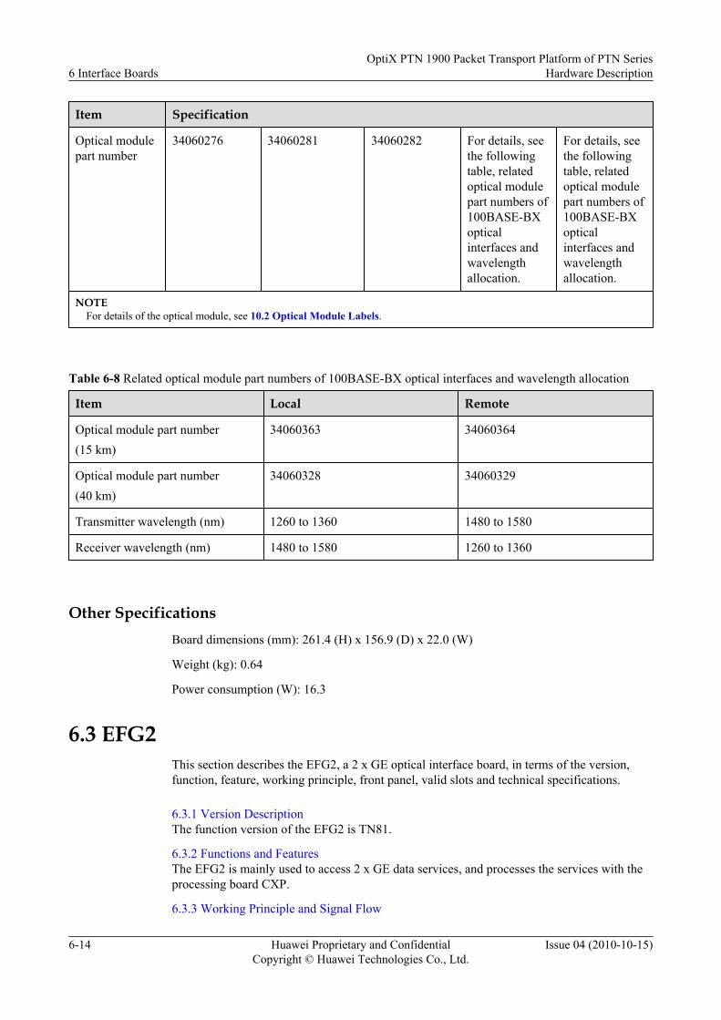
Item Specification
Optical modulepart number
34060276 34060281 34060282 For details, seethe followingtable, relatedoptical modulepart numbers of100BASE-BXopticalinterfaces andwavelengthallocation.
For details, seethe followingtable, relatedoptical modulepart numbers of100BASE-BXopticalinterfaces andwavelengthallocation.
NOTEFor details of the optical module, see 10.2 Optical Module Labels.
Table 6-8 Related optical module part numbers of 100BASE-BX optical interfaces and wavelength allocation
Item Local Remote
Optical module part number(15 km)
34060363 34060364
Optical module part number(40 km)
34060328 34060329
Transmitter wavelength (nm) 1260 to 1360 1480 to 1580
Receiver wavelength (nm) 1480 to 1580 1260 to 1360
Other SpecificationsBoard dimensions (mm): 261.4 (H) x 156.9 (D) x 22.0 (W)
Weight (kg): 0.64
Power consumption (W): 16.3
6.3 EFG2This section describes the EFG2, a 2 x GE optical interface board, in terms of the version,function, feature, working principle, front panel, valid slots and technical specifications.
6.3.1 Version DescriptionThe function version of the EFG2 is TN81.
6.3.2 Functions and FeaturesThe EFG2 is mainly used to access 2 x GE data services, and processes the services with theprocessing board CXP.
6.3.3 Working Principle and Signal Flow
6 Interface BoardsOptiX PTN 1900 Packet Transport Platform of PTN Series
Hardware Description
6-14 Huawei Proprietary and ConfidentialCopyright © Huawei Technologies Co., Ltd.
Issue 04 (2010-10-15)
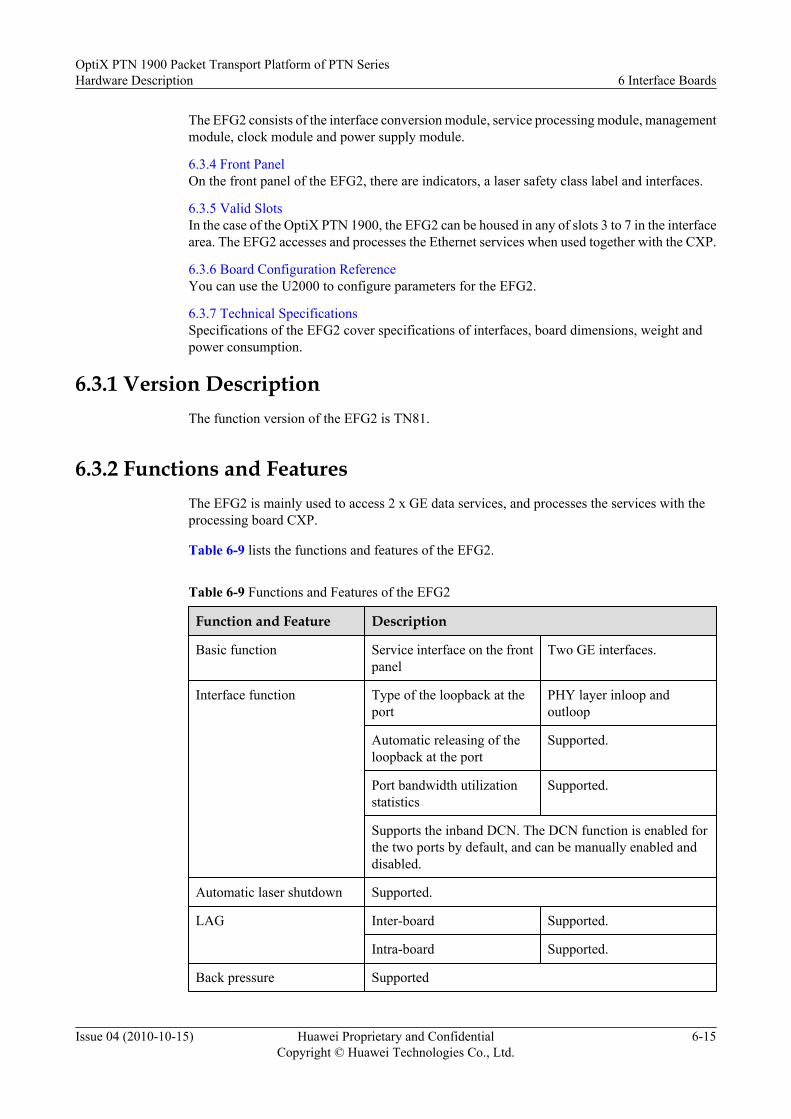
The EFG2 consists of the interface conversion module, service processing module, managementmodule, clock module and power supply module.
6.3.4 Front PanelOn the front panel of the EFG2, there are indicators, a laser safety class label and interfaces.
6.3.5 Valid SlotsIn the case of the OptiX PTN 1900, the EFG2 can be housed in any of slots 3 to 7 in the interfacearea. The EFG2 accesses and processes the Ethernet services when used together with the CXP.
6.3.6 Board Configuration ReferenceYou can use the U2000 to configure parameters for the EFG2.
6.3.7 Technical SpecificationsSpecifications of the EFG2 cover specifications of interfaces, board dimensions, weight andpower consumption.
6.3.1 Version DescriptionThe function version of the EFG2 is TN81.
6.3.2 Functions and FeaturesThe EFG2 is mainly used to access 2 x GE data services, and processes the services with theprocessing board CXP.
Table 6-9 lists the functions and features of the EFG2.
Table 6-9 Functions and Features of the EFG2
Function and Feature Description
Basic function Service interface on the frontpanel
Two GE interfaces.
Interface function Type of the loopback at theport
PHY layer inloop andoutloop
Automatic releasing of theloopback at the port
Supported.
Port bandwidth utilizationstatistics
Supported.
Supports the inband DCN. The DCN function is enabled forthe two ports by default, and can be manually enabled anddisabled.
Automatic laser shutdown Supported.
LAG Inter-board Supported.
Intra-board Supported.
Back pressure Supported
OptiX PTN 1900 Packet Transport Platform of PTN SeriesHardware Description 6 Interface Boards
Issue 04 (2010-10-15) Huawei Proprietary and ConfidentialCopyright © Huawei Technologies Co., Ltd.
6-15

Function and Feature Description
Clock Synchronous Ethernet Supported by the opticalinterfaces.
IEEE 1588 V2 protocol1588 ACR clock
Supported by the opticalinterfaces.
Transmitting and receivingthe synchronous statusmessage (SSM) ofsynchronous Ethernet ports.
Supported by the opticalinterfaces.
6.3.3 Working Principle and Signal FlowThe EFG2 consists of the interface conversion module, service processing module, managementmodule, clock module and power supply module.
Figure 6-5 shows the block diagram for the working principle of the EFG2.
Figure 6-5 Block diagram for the working principle of the EFG2
CXP AInterface conversion
module
Clock module
Service processing
module
Management module
2 x GE signals Service signalsService signals
Management bus
Management bus
System clock
-48V/-60V
-48V/-60V
3.3V...
1.2V
PIU
PIU
Power module
.
.
.
CXP
Backplane
IEEE 1588 V2 packetsSynchronous Ethernet clocksManagement bus
Synchronous Ethernet clocks
IEEE 1588 V2 packets
CXP BService signals
CXPCXPCXP
In the Downstream DirectionThe service packets from the CXP are accessed through the ports on the backplane of the EFG2,and then sent to the service processing module. The service processing module buffers andgrooms the service packets, and sends the processing packets to the interface conversion module,which performs the coding/decoding and parallel/serial conversion on the service packets.Finally, the service signals are sent though the GE ports.
In the Upstream DirectionThe GE services are accessed to the interface conversion module through the GE ports. Theinterface conversion module performs the coding/decoding and serial/parallel conversion, andthen sends the packets to the service processing module, which buffers and grooms the service
6 Interface BoardsOptiX PTN 1900 Packet Transport Platform of PTN Series
Hardware Description
6-16 Huawei Proprietary and ConfidentialCopyright © Huawei Technologies Co., Ltd.
Issue 04 (2010-10-15)

packets. Finally, the high speed packets are sent to the CXP through the interface on the portson the backplane.
Interface Conversion ModuleThis module performs the following functions:
l In the upstream direction, this module accesses the GE services, and then performs thecoding/decoding and serial/parallel conversion. Finally, the processing service packets aresent to the service processing module.
l In the downstream direction, this module receives the service packets sent by the serviceprocessing module, and performs the coding/decoding and serial/parallel conversion.Finally, the service packets are sent to each GE port.
Service Processing ModuleThis module performs the following functions:
l In the upstream direction, this module receives the service packets sent by the interfaceconversion module, and buffers and grooms the service packets, and then sends the packetsto the ports on the backplane.
l In the downstream direction, this module buffers and grooms the service packets sentthrough the ports on the backplane, and then sends the packets to the interface conversionmodule.
l Extracts and inserts synchronous Ethernet clock signals.l Extracts and inserts IEEE 1588 V2 packets.
Management ModuleThis module manages and controls the modules on the board.
Clock ModuleThis module performs the following functions:
l Provides the working clocks for the modules on the boards.l Supports the synchronous Ethernet.l Supports the IEEE 1588 V2 protocol.l Supports the 1588 ACR clock.
Power Supply ModuleThis module supplies 1.2 V and 3.3 V power for the board.
6.3.4 Front PanelOn the front panel of the EFG2, there are indicators, a laser safety class label and interfaces.
Appearance of the Front PanelFigure 6-6 shows the appearance of the front panel of the EFG2.
OptiX PTN 1900 Packet Transport Platform of PTN SeriesHardware Description 6 Interface Boards
Issue 04 (2010-10-15) Huawei Proprietary and ConfidentialCopyright © Huawei Technologies Co., Ltd.
6-17

Figure 6-6 Appearance of the front panel of the EFG2
IndicatorThe following indicators are present on the front panel of the EFG2.
l STAT indicator, red, green, or orange, which indicates the working statusl ACT indicator, green, which indicates the service activation statusl SRV indicator, red, green, or orange, which indicates the service statusl L/A1, L/A2 indicators, green or orange, which indicate the port connection state or data
transmission state.
For details on indications of indicators, see A.2 Board Indicators.
6 Interface BoardsOptiX PTN 1900 Packet Transport Platform of PTN Series
Hardware Description
6-18 Huawei Proprietary and ConfidentialCopyright © Huawei Technologies Co., Ltd.
Issue 04 (2010-10-15)

Laser Safety Class LabelThe laser safety class is of CLASS 1. For an optical interface of this class, the maximum outputoptical power is less than 10 dBm (10 mW).
InterfaceOn the EFG2, two SFP interfaces are present. Table 6-10 and Table 6-11 list the types and usageof the interfaces. For fiber corresponding to the interfaces, see 12.1.1 Types of Fiber. For cablescorresponding to the interfaces, see 12.4.1 Straight Through Cable and 12.4.2 CrossoverCable.
Table 6-10 Types and usage of the interfaces on the EFG2
Interface on the Front Panel Interface Type Usage
Optical interfaces IN1-IN2 LC When a two-fiber bidirectional optical module isused, this interface is used as an input interface forthe GE optical signal.When a single-fiber bidirectional optical moduleis used, this interface is not used.
OUT1-OUT2 LC When a two-fiber bidirectional optical module isused, this interface is used as an output interfacefor the GE optical signal.When a single-fiber bidirectional optical moduleis used, this interface is used as an input/outputinterface for the GE optical signal.
Electricalinterfaces
OUT1 IN1-OUT2IN2
RJ-45 Input/Output interfaces for GE electrical signalsFor the pins for the GE electrical interface, seeTable 6-11.
NOTEThe SFP interface on the front panel can function as either an optical interface or an electrical interface.
When the SFP interface functions as an optical interface, it need to be used with an optical module.
l When a two-fiber bidirectional optical module is used, two LC interfaces are provided on the left and right sides of the opticalmodule. Each interface uses one fiber, which is used to transmit or receive service signals.
l When a single-fiber bidirectional optical module is used, only one LC interface is provided on the left side of the opticalmodule. This optical interface uses only one fiber, which is used to transmit and receive service signals at the same time.
When the SFP interface functions as an electrical interface, it need to be used with an electrical module.
OptiX PTN 1900 Packet Transport Platform of PTN SeriesHardware Description 6 Interface Boards
Issue 04 (2010-10-15) Huawei Proprietary and ConfidentialCopyright © Huawei Technologies Co., Ltd.
6-19

Table 6-11 Pins for the GE electrical interface
Front View Pin Usage
18 24 3567
1 Positive of twisted pair cable 1
2 Negative of twisted pair cable 1
3 Positive of twisted pair cable 2
4 Positive of twisted pair cable 3
5 Negative of twisted pair cable 3
6 Negative of twisted pair cable 2
7 Positive of twisted pair cable 4
8 Negative of twisted pair cable 4
6.3.5 Valid SlotsIn the case of the OptiX PTN 1900, the EFG2 can be housed in any of slots 3 to 7 in the interfacearea. The EFG2 accesses and processes the Ethernet services when used together with the CXP.
6.3.6 Board Configuration ReferenceYou can use the U2000 to configure parameters for the EFG2.
You can use the U2000 to configure the following parameters for the EFG2.
l Ethernet Interfacel Automatic Laser Shutdown
For details on the parameters, see D Board Configuration Parameters.
6.3.7 Technical SpecificationsSpecifications of the EFG2 cover specifications of interfaces, board dimensions, weight andpower consumption.
Table 6-12 lists the specifications of interfaces on the EFG2.
Table 6-12 Technical specifications of the GE optical interface
Item Specification
Opticalinterface type
Two-fiber bidirectional interface Single-fiberbidirectionalinterface
1000BASE-SX(0.5 km)
1000BASE-LX(10 km)
1000BASE-VX(40 km)
1000BASE-ZX(80 km)
1000BASE-CWDM(80 km)
1000BASE-BX(10 km)
6 Interface BoardsOptiX PTN 1900 Packet Transport Platform of PTN Series
Hardware Description
6-20 Huawei Proprietary and ConfidentialCopyright © Huawei Technologies Co., Ltd.
Issue 04 (2010-10-15)

Item Specification
Fiber type Multi-mode Single-mode Single-mode Single-mode Single-mode Single-mode
Workingwavelengthrange (nm)
770 to 860 1270 to 1360 1260 to 1360 1500 to 1580 For details, seethe followingtable, relatedoptical modulepart numbersof 1000BASE-CWDMopticalinterfaces andwavelengthallocation.
For details, seethe followingtable, relatedoptical modulepart numbersof 1000BASE-BX opticalinterfaces andwavelengthallocation.
Meanlaunchedoptical power(dBm)
-9.5 to 0 -11 to -3 -5 to 0 -2 to 5 0 to 5 -9 to -3
Receiversensitivity(dBm)
-17 -19 -22 -22 -28 -19.5
Minimumoverload(dBm)
0 -3 -3 -3 -9 -3
Minimumextinctionratio (dB)
9 9 9 9 8.2 6
Opticalmodule partnumber
34060286 34060473 34060298 34060360 For details, seethe followingtable, relatedoptical modulepart numbersof 1000BASE-CWDMopticalinterfaces andwavelengthallocation.
For details, seethe followingtable, relatedoptical modulepart numbersof 1000BASE-BX opticalinterfaces andwavelengthallocation.
NOTEFor details of the optical module, see 10.2 Optical Module Labels.
OptiX PTN 1900 Packet Transport Platform of PTN SeriesHardware Description 6 Interface Boards
Issue 04 (2010-10-15) Huawei Proprietary and ConfidentialCopyright © Huawei Technologies Co., Ltd.
6-21

Table 6-13 Related optical module part numbers of 1000BASE-CWDM optical interfaces and related optical modulewavelength allocation
SN Optical modulepart number
Wavelength (nm) SN Opticalmodule partnumber
Wavelength (nm)
1 34060483 1464.5 to 1477.5 5 34060478 1544.5 to 1557.5
2 34060481 1484.5 to 1497.5 6 34060476 1564.5 to 1577.5
3 34060479 1504.5 to 1517.5 7 34060477 1584.5 to 1597.5
4 34060482 1524.5 to 1537.5 8 34060480 1604.5 to 1617.5
Table 6-14 Related optical module part numbers of 1000BASE-BX optical interfaces and wavelength allocation
Item Local Remote
Optical part number 34060470 34060475
Transmitter wavelength (nm) 1260 to 1360 1480 to 1500
Receiver wavelength (nm) 1480 to 1500 1260 to 1360
Table 6-15 Specifications of the electrical interfaces on the EFG2
Item Specification Requirement
Interface rate 1000 Mbit/s
RJ-45 electrical interfacespecification
Complies with IEEE 802.3 and enterpriseregulations.
Board dimensions (mm): 261.4 (H) x 156.9 (D) x 22.0 (W)
Weight (kg): 0.52
Power consumption (W): 8.8
6.4 POD41This section describes the POD41, a 2 x 622M/155M POS interface board, in terms of theversion, function, feature, working principle, front panel, valid slots and technical specifications.
6.4.1 Version DescriptionThe function version of the POD41 is TN81.
6.4.2 Functions and FeaturesThe POD41 mainly accesses 2 x STM-4/STM-1 services. The POD41 should be used with theprocessing board CXP.
6 Interface BoardsOptiX PTN 1900 Packet Transport Platform of PTN Series
Hardware Description
6-22 Huawei Proprietary and ConfidentialCopyright © Huawei Technologies Co., Ltd.
Issue 04 (2010-10-15)

6.4.3 Working Principle and Signal FlowThe POD41 mainly consists of the interface conversion module, service processing module,management module, power supply module, and clock module.
6.4.4 Front PanelOn the front panel of the POD41, there are indicators, a laser safety class l label and interfaces.
6.4.5 Valid SlotsFor the OptiX PTN 1900, the POD41 can be housed in any of slots 3-7 in the interface area.When used with the active and standby CXP, the POD41 can access and process STM-1/STM-4line signals.
6.4.6 Board Configuration ReferenceYou can use the U2000 to configure parameters for the POD41.
6.4.7 Technical SpecificationsSpecifications of the POD41 board cover specifications of interfaces, board dimensions, weightand power consumption.
6.4.1 Version DescriptionThe function version of the POD41 is TN81.
6.4.2 Functions and FeaturesThe POD41 mainly accesses 2 x STM-4/STM-1 services. The POD41 should be used with theprocessing board CXP.
Table 6-16 lists the following functions and features of the POD41.
Table 6-16 Functions and Features of the POD41
Function and Feature Description
Basic function Service interface on the frontpanel
Two STM-1/STM-4 opticalinterfaces
Interface function Type of the loopback at theport
InloopOutloop
Automatic releasing of theloopback at the port
Supported.
Automatic laser shutdown Supported.
Port bandwidth utilizationstatistics
Supported.
Supports the inband DCN. The DCN function is enabled forthe two ports by default, and can be manually enabled anddisabled.
Used as the NNI.
LMSP protection Supports the 1+1 LMSP and 1:1 LMSP protection. Theprotection switching time is less than 50 ms.
OptiX PTN 1900 Packet Transport Platform of PTN SeriesHardware Description 6 Interface Boards
Issue 04 (2010-10-15) Huawei Proprietary and ConfidentialCopyright © Huawei Technologies Co., Ltd.
6-23

Function and Feature Description
Clock Recovers the line clocks
6.4.3 Working Principle and Signal FlowThe POD41 mainly consists of the interface conversion module, service processing module,management module, power supply module, and clock module.
Figure 6-7 shows the block diagram for the working principle of the POD41.
Figure 6-7 Block diagram for the working principle of the POD41
CXP AInterface conversion
module
Clock module
Service processing
module
Management module
2 x STM-1/STM-4 signals
Service signalsService signals
Management bus
Management bus
System clock
-48V/-60V
-48V/-60V
3.3V...
1.2V
PIU
PIU
Power supply module
.
.
.
Backplane
Line clocksManagement bus
Line clocksCXP
CXP
CXP
CXP BService signals
Interface Conversion ModuleThis module converts rates of interfaces.
Service Processing ModuleThis module converts the STM-4 or STM-1 serial differential signals to parallel signals, andoutputs the parallel signals through the interfaces. In addition, this module sends the frame alarmsignals, received alarm signals and inserted signals indicating bit error found during the paritycheck. Finally, this module reports its status through the management module.
Management ModuleThis module manages and controls the modules on the board.
Power supply moduleThis module provides DC voltages required by each module on the board.
Clock ModuleThis module locks the phase for the system clock and provides the line clock.
6 Interface BoardsOptiX PTN 1900 Packet Transport Platform of PTN Series
Hardware Description
6-24 Huawei Proprietary and ConfidentialCopyright © Huawei Technologies Co., Ltd.
Issue 04 (2010-10-15)
6.4.4 Front PanelOn the front panel of the POD41, there are indicators, a laser safety class l label and interfaces.
Appearance of the Front Panel
Figure 6-8 shows the appearance of the front panel of the POD41.
Figure 6-8 Appearance of the front panel of the POD41
Indicatorl STAT indicator, red, green, or orange, which indicates the working status
l ACT indicator, green, which indicates the service activation status
OptiX PTN 1900 Packet Transport Platform of PTN SeriesHardware Description 6 Interface Boards
Issue 04 (2010-10-15) Huawei Proprietary and ConfidentialCopyright © Huawei Technologies Co., Ltd.
6-25

l SRV indicator, red, green, or orange, which indicates the service status
For details on indications of indicators, see A.2 Board Indicators.
Laser Safety Class Label
The laser safety class is of CLASS 1. For an optical interface of this class, the maximum outputoptical power is less than 10 dBm (10 mW).
Interface
Two SFP interfaces are present on the front panel of the POD41. Table 6-17 lists the types andusage of the interfaces. For fiber corresponding to the interfaces, see 12.1.1 Types of Fiber.
Table 6-17 Types and usage of the interfaces on the POD41
Interface onthe FrontPanel
InterfaceType
Usage
IN1-IN2 LC When a two-fiber bidirectional optical module is used, thisinterface is used as an input interface for the STM-1/STM-4optical signal.When a single-fiber bidirectional optical module is used, thisinterface is not used.
OUT1-OUT2 LC When a two-fiber bidirectional optical module is used, thisinterface is used as an output interface for the STM-1/STM-4optical signal.When a single-fiber bidirectional optical module is used, thisinterface is used as an input/output interface for the STM-1optical signal.The STM-4 interface does not support the single-fiberbidirectional optical module.
NOTEThe SFP interface should be used with an optical module.
l When a two-fiber bidirectional optical module is used, two LC interfaces are provided on the left andright sides of the optical module. Each interface uses one fiber, which is used to transmit or receiveservice signals.
l When a single-fiber bidirectional optical module is used, only one LC interface is provided on the leftside of the optical module. This optical interface uses only one fiber, which is used to transmit andreceive service signals at the same time.
6.4.5 Valid SlotsFor the OptiX PTN 1900, the POD41 can be housed in any of slots 3-7 in the interface area.When used with the active and standby CXP, the POD41 can access and process STM-1/STM-4line signals.
6 Interface BoardsOptiX PTN 1900 Packet Transport Platform of PTN Series
Hardware Description
6-26 Huawei Proprietary and ConfidentialCopyright © Huawei Technologies Co., Ltd.
Issue 04 (2010-10-15)

6.4.6 Board Configuration ReferenceYou can use the U2000 to configure parameters for the POD41.
You can use the U2000 to configure the following parameters for the POD41.
l Automatic Laser Shutdown
l J0
l J1
l C2
l SDH Interface
For details on the parameters, see D Board Configuration Parameters.
6.4.7 Technical SpecificationsSpecifications of the POD41 board cover specifications of interfaces, board dimensions, weightand power consumption.
Table 6-18 and Table 6-20 list the specifications of interfaces on the POD41.
Table 6-18 Technical specifications of the STM-1 optical interface
Item Specification
Nominal bit rate(kbit/s)
155520
Optical interfacetype
Two-fiber bidirectional interface Single-fiber bidirectional interface
S-1.1(15 km)
L-1.1(40 km)
L-1.2(80 km)
S-1.1(10 km)
L-1.1(40 km)
Fiber type Single-mode Single-mode Single-mode Single-mode Single-mode
Workingwavelengthrange (nm)
1261 to 1360 1263 to 1360 1480 to 1580 For details, seethe followingtable, relatedoptical modulepart numbers ofsingle-fiberbidirectionaloptical interfaceand wavelengthallocation.
For details, seethe followingtable, relatedoptical modulepart numbers ofsingle-fiberbidirectionaloptical interfaceand wavelengthallocation.
Mean launchedoptical power(dBm)
-15 to -8 -5 to 0 -5 to 0 -15 to -8 -5 to 0
Receiversensitivity(dBm)
-28 -34 -34 -28.2 -30
OptiX PTN 1900 Packet Transport Platform of PTN SeriesHardware Description 6 Interface Boards
Issue 04 (2010-10-15) Huawei Proprietary and ConfidentialCopyright © Huawei Technologies Co., Ltd.
6-27

Item Specification
Minimumoverload (dBm)
-8 -10 -10 -8 -10
Minimumextinction ratio(dB)
8.2 10 10 6.6 10
Optical modulepart number
34060276 34060281 34060282 For details, seethe followingtable, relatedoptical modulepart numbers ofsingle-fiberbidirectionaloptical interfaceand wavelengthallocation.
For details, seethe followingtable, relatedoptical modulepart number ofsingle-fiberbidirectionaloptical interfaceand wavelengthallocation.
NOTEFor details of the optical module, see 10.2 Optical Module Labels.
Table 6-19 Related optical module part numbers of single-fiber bidirectional interface optical interface andwavelength allocation
Item Local Remote
Optical module part number(15 km)
34060363 34060364
Optical module part number(40 km)
34060328 34060329
Transmitter wavelength (nm) 1260 to 1360 1480 to 1580
Receiver wavelength (nm) 1480 to 1580 1260 to 1360
Table 6-20 Technical specifications of the STM-4 optical interface
Item Specification
Nominal bit rate (kbit/s) 622080
Optical interface type Two-fiber bidirectional interface
S-4.1(15 km)
L-4.1(40 km)
L-4.2(80 km)
Fiber type Single-mode Single-mode Single-mode
Working wavelength range (nm) 1261 to 1360 1280 to 1355 1480 to 1580
6 Interface BoardsOptiX PTN 1900 Packet Transport Platform of PTN Series
Hardware Description
6-28 Huawei Proprietary and ConfidentialCopyright © Huawei Technologies Co., Ltd.
Issue 04 (2010-10-15)

Item Specification
Launched optical power (dBm) -15 to -8 -3 to 2 -3 to 2
Receiver sensitivity (dBm) -28 -28 -28
Minimum overload (dBm) -8 -8 -8
Minimum extinction ratio (dB) 8.2 10 10
Optical module code 34060277 34060280 34060284
NOTEFor details of the optical module, see 10.2 Optical Module Labels.
Board dimensions (mm): 261.4 (H) x 156.9 (D) x 22.0 (W)
Weight (kg): 0.55
Power consumption (W): 11.6
6.5 AFO1This section describes the AFO1, an 8-channel ATM STM-1 service interface board, in termsof the version, function, feature, working principle, front panel, valid slots, and technicalspecifications.
6.5.1 Version DescriptionThe function version of the AFO1 is TN81.
6.5.2 Functions and FeaturesThe AFO1 is used to access 8 x ATM STM-1 services. When used with the processing boardCXP, the AFO1 can process the ATM services.
6.5.3 Working Principle and Signal FlowThe AFO1 mainly consists of the ATM access module, ATM processing module, data processingmodule, management module, clock module, and power supply module.
6.5.4 Front PanelOn the front panel of the AFO1, there are indicators and eight optical interfaces.
6.5.5 Valid SlotsIn the case of the OptiX PTN 1900, the AFO1 can be housed in any of slots 3 to 7 in the interfacearea. The AFO1 accesses and processes the ATM STM-1 services when used together with theCXP.
6.5.6 Board Configuration ReferenceYou can use the U2000 to set parameters for the AFO1.
6.5.7 Technical SpecificationsThe technical specifications of the AFO1 cover the interface specifications, board dimensions,weight and power consumption.
6.5.1 Version DescriptionThe function version of the AFO1 is TN81.
OptiX PTN 1900 Packet Transport Platform of PTN SeriesHardware Description 6 Interface Boards
Issue 04 (2010-10-15) Huawei Proprietary and ConfidentialCopyright © Huawei Technologies Co., Ltd.
6-29

6.5.2 Functions and FeaturesThe AFO1 is used to access 8 x ATM STM-1 services. When used with the processing boardCXP, the AFO1 can process the ATM services.
Table 6-21 lists the functions and features of the AFO1.
Table 6-21 Functions and Features of the AFO1
Function andFeature
Description
Basic function Service interface on thefront panel
Eight ATM STM-1 optical interfaces
Interface function Automatic shutdown of thelaser at the port
Supported.
Type of the loopback at theport
InloopOutloop
Automatic releasing of theloopback at the port
Supported.
ATM Supported traffic type CBRUBRUBR+rt-VBRnrt-VBR
Number of supported PW 4 k
Number of supported ATMVP/VC switchingconnections
2 k
Supports the encapsulation from ATM VPC/VCC to PWE3 in the N-to-1 (N≤32) and 1-to-1 formats.
Supports the PW encapsulation for the ATM cells in the concatenationand non-concatenation formats. The number of PW connections thatsupport the cell concatenation is 2 k, and the maximum number ofconcatenated cells is 31.
UNI-side ATM OAM Supports the CC test.
Supports the LB test.
Supports the AIS.
Supports the RDI.
6 Interface BoardsOptiX PTN 1900 Packet Transport Platform of PTN Series
Hardware Description
6-30 Huawei Proprietary and ConfidentialCopyright © Huawei Technologies Co., Ltd.
Issue 04 (2010-10-15)

Function andFeature
Description
LMSP protection Supports the LMSP. The protection switching time is less than 50 ms.l Supports the inter-board and intra-board 1+1 LMSP.l Supports the intra-board 1:1 LMSP.l Supports one group of intra-board 1:N (N≤7) LMSP.
Extraction andinsertion of S1 bytes
Supported.
6.5.3 Working Principle and Signal FlowThe AFO1 mainly consists of the ATM access module, ATM processing module, data processingmodule, management module, clock module, and power supply module.
Figure 6-9 shows the block diagram for the working principle of the AFO1.
Figure 6-9 Block diagram for the working principle of the AFO1
Clock module
Power supply module
-48 V/-60 V
-48 V/-60 V
Service signals
PIU
PIU
CXP
CXP A
System clock signals
3.3 V ...
1.1 V
Backplane
CXP BService signals
ATM processing module
ATM access module
Data processing module
Management module
Management bus
Management bus
8 x STM-1 ATM signals ATM cells ATM cells
Management bus Management bus
CXP
In the upstream DirectionThe ATM STM-1 service signals accesses the ATM access module through the optical interface.The ATM access module extracts the ATM cells, and transmits the cells to the ATM processingmodule for service processing. Then, QoS functions such as VP/VC switching, ATM OAM, andtraffic management are performed on the cells. The PW encapsulation is performed on theprocessed cells on the data processing module. Finally, the cells are transmitted to the processingboard CXP through the port on the backplane.
OptiX PTN 1900 Packet Transport Platform of PTN SeriesHardware Description 6 Interface Boards
Issue 04 (2010-10-15) Huawei Proprietary and ConfidentialCopyright © Huawei Technologies Co., Ltd.
6-31

In the downstream Direction
The data services are accessed to the processing module through the port on the backplane. ThePW decapsulation is performed on the services, and then the services are sent to the ATMprocessing module. On the ATM processing module, QoS functions such as ATM OAM andtraffic management are performed on the services. Then, the services are sent to the ATM accessmodule, where the TAM cells are mapped to SDH signals. Then, the signals are sent out throughthe corresponding optical interface.
ATM Access Module
This module performs the following functions:
l In the upstream direction, the SDH overheads, alarms, and pointers are processed on theaccessed 8 x ATM STM-1 signals at a rate of 155 Mbit/s. The ATM cells are extractedfrom the SDH signals, and then the ATM cells are sent to the ATM processing module,where the line clock is extracted.
l In the downstream direction, the ATM cells from the ATM processing module are mappedto the SDH signals, and then the SDH overhead processing, alarm processing, and pointerprocessing are performed on the signals. In this manner, the SDH frames are formed.
ATM Processing Module
This module mainly realizes the VP/VC switching, QoS functions such as traffic management,traffic shaping, queue scheduling, and OAM function for the ATM cells.
l In the upstream direction, this module determines the traffic priority of the ATM cells. Ifcongestion occurs, this module determines whether to discard the cells or to continuetransmitting cells according to the traffic priority. If the cells are continued to be transmitted,the VP/VC switching is performed on the cells, which are then sent to the data processingmodule.
l In the downstream direction, this module processes the cell packet headers, and performsthe VP/VC switching on the cells. If congestion occurs, this module determines whetherto discard the cells or to continue transmitting cells according to the traffic priority. If thecells are continued to be transmitted, they are sent to the ATM access module.
l Provides the back pressure mechanism, and realizes the traffic management function.
l Supports the F4 and F5 ATM OAM functions:
– Supports the CC test.
– Supports the LB test.
Data Processing Module
This module mainly realizes the PW encapsulation and decapsulation for the packets.
l In the upstream direction, this module receives the ATM cells, and performs the PWencapsulation for the cells in the concatenation or non-concatenation format. Then, the cellsare sent to the processing board CXP through the port on the backplane.
l In the downstream direction, this module receives the PWE3 packets from the port on thebackplane, identifies the packets, performs the PW decapsulation to obtain the ATM cells,and then transmits the cells to the ATM processing module.
6 Interface BoardsOptiX PTN 1900 Packet Transport Platform of PTN Series
Hardware Description
6-32 Huawei Proprietary and ConfidentialCopyright © Huawei Technologies Co., Ltd.
Issue 04 (2010-10-15)

Management ModuleThis module performs the following functions:
l Manages and controls other modules on the board.l Processes various clock signals when used with the clock module.
Clock ModuleThis module provides clock signals for other modules of the board.
Power Supply ModuleThis module provides the working power supply for each module of the board.
6.5.4 Front PanelOn the front panel of the AFO1, there are indicators and eight optical interfaces.
Appearance of the Front PanelFigure 6-10 shows the appearance of the front panel of the AFO1.
OptiX PTN 1900 Packet Transport Platform of PTN SeriesHardware Description 6 Interface Boards
Issue 04 (2010-10-15) Huawei Proprietary and ConfidentialCopyright © Huawei Technologies Co., Ltd.
6-33

Figure 6-10 Front panel of the AFO1
IndicatorsThe following indicators are present on the front panel of the AFO1:
l STAT indicator, red, green, or orange, which indicates the working statusl ACT indicator, green, which indicates the service activation statusl SRV indicator, red, green, or orange, which indicates the service status
For details on indications of indicators, see A.2 Board Indicators.
InterfacesEight SFP interfaces are present on the AFO1. Table 6-22 lists the number, types, and usage ofthe interfaces on the AFO1. For fiber corresponding to the interfaces, see 12.1.1 Types ofFiber.
6 Interface BoardsOptiX PTN 1900 Packet Transport Platform of PTN Series
Hardware Description
6-34 Huawei Proprietary and ConfidentialCopyright © Huawei Technologies Co., Ltd.
Issue 04 (2010-10-15)

Table 6-22 Types and usage of the interfaces on the AFO1
Interface on theFront Panel
InterfaceType
Usage
IN1 - IN8 LC When a two-fiber bidirectional optical module is used,this interface is used as an input interface for the STM-1optical signal.When a single-fiber bidirectional optical module isused, this interface is not used.
OUT1 - OUT8 LC When a two-fiber bidirectional optical module is used,this interface is used as an output interface for theSTM-1 optical signal.When a single-fiber bidirectional optical module isused, this interface is used as an input/output interfacefor the STM-1 optical signal.
NOTEThe SFP interface should be used with an optical module.
l When a two-fiber bidirectional optical module is used, two LC interfaces are provided on the left andright sides of the optical module. Each interface uses one fiber, which is used to transmit or receiveservice signals.
l When a single-fiber bidirectional optical module is used, only one LC interface is provided on the leftside of the optical module. This optical interface uses only one fiber, which is used to transmit andreceive service signals at the same time.
6.5.5 Valid SlotsIn the case of the OptiX PTN 1900, the AFO1 can be housed in any of slots 3 to 7 in the interfacearea. The AFO1 accesses and processes the ATM STM-1 services when used together with theCXP.
NOTE
If the AFO1 is housed in slot 3, the last port of the AFO1 cannot be used.
6.5.6 Board Configuration ReferenceYou can use the U2000 to set parameters for the AFO1.
You can use the U2000 to set the following parameters for the AFO1:
l Automatic laser shutdown
l SDH interface
For details on the parameters, see D Board Configuration Parameters.
6.5.7 Technical SpecificationsThe technical specifications of the AFO1 cover the interface specifications, board dimensions,weight and power consumption.
OptiX PTN 1900 Packet Transport Platform of PTN SeriesHardware Description 6 Interface Boards
Issue 04 (2010-10-15) Huawei Proprietary and ConfidentialCopyright © Huawei Technologies Co., Ltd.
6-35

Interface SpecificationsTable 6-23 lists the specifications of interfaces on the AFO1.
Table 6-23 Technical specifications of the STM-1 optical interface
Item Specification
Nominal bit rate(kbit/s)
155520
Optical interfacetype
Two-fiber bidirectional interface Single-fiber bidirectional interface
S-1.1(15 km)
L-1.1(40 km)
L-1.2(80 km)
S-1.1(10 km)
L-1.1(40 km)
Fiber type Single-mode Single-mode Single-mode Single-mode Single-mode
Workingwavelengthrange (nm)
1261 to 1360 1263 to 1360 1480 to 1580 For details, seethe followingtable, relatedoptical modulepart numbers ofsingle-fiberbidirectionaloptical interfaceand wavelengthallocation.
For details, seethe followingtable, relatedoptical modulepart numbers ofsingle-fiberbidirectionaloptical interfaceand wavelengthallocation.
Mean launchedoptical power(dBm)
-15 to -8 -5 to 0 -5 to 0 -15 to -8 -5 to 0
Receiversensitivity(dBm)
-28 -34 -34 -28.2 -30
Minimumoverload (dBm)
-8 -10 -10 -8 -10
Minimumextinction ratio(dB)
8.2 10 10 6.6 10
Optical modulepart number
34060276 34060281 34060282 For details, seethe followingtable, relatedoptical modulepart numbers ofsingle-fiberbidirectionaloptical interfaceand wavelengthallocation.
For details, seethe followingtable, relatedoptical modulepart number ofsingle-fiberbidirectionaloptical interfaceand wavelengthallocation.
6 Interface BoardsOptiX PTN 1900 Packet Transport Platform of PTN Series
Hardware Description
6-36 Huawei Proprietary and ConfidentialCopyright © Huawei Technologies Co., Ltd.
Issue 04 (2010-10-15)

Item Specification
NOTEFor details of the optical module, see 10.2 Optical Module Labels.
Table 6-24 Related optical module part numbers of single-fiber bidirectional interface optical interface andwavelength allocation
Item Local Remote
Optical module part number(15 km)
34060363 34060364
Optical module part number(40 km)
34060328 34060329
Transmitter wavelength (nm) 1260 to 1360 1480 to 1580
Receiver wavelength (nm) 1480 to 1580 1260 to 1360
Other SpecificationsBoard dimensions (mm): 261.4 (H) x 156.9 (D) x 22.0 (W)
Weight (kg): 0.78
Power consumption (W): 27.2
6.6 L75/L12This section describes the L75/L12, a 16 x E1 75-ohm interface board, in terms of the version,function, feature, working principle, front panel, valid slots and technical specifications.
NOTE
The mapping impedance of an interface on the L75 is 75 ohm, and the mapping impedance of an interfaceon the L12 is 120 ohm. Except the difference of mapping impedance, the functions and features of the L75and L12 are the same.
6.6.1 Version DescriptionThe function version of the L75/L12 is TN71.
6.6.2 Function and FeatureThe L75 is mainly used to input and output 16 x 75-ohm E1 signals, and the L12 is mainly usedto input and output 16 x 120-ohm E1 signals. Used with the MD1 and the CXP, the L75/L12provides TPS protection for E1 services.
6.6.3 Working Principle and Signal FlowThe L75/L12 mainly consists of the isolation protection module, relay trail selecting moduleand power supply module.
6.6.4 Front PanelOn the front panel of the L75/L12, there are interfaces.
OptiX PTN 1900 Packet Transport Platform of PTN SeriesHardware Description 6 Interface Boards
Issue 04 (2010-10-15) Huawei Proprietary and ConfidentialCopyright © Huawei Technologies Co., Ltd.
6-37

6.6.5 Valid SlotsThe slot that houses the L75/L12 in the interface area is determined by the slot that houses theprocessing board used with the L75/L12.
6.6.6 Board Configuration ReferenceYou can use the U2000 to configure parameters for the L75/L12.
6.6.7 Technical SpecificationsSpecifications of the L75/L12 board cover interface specifications, board dimensions, weightand power consumption.
6.6.1 Version DescriptionThe function version of the L75/L12 is TN71.
6.6.2 Function and FeatureThe L75 is mainly used to input and output 16 x 75-ohm E1 signals, and the L12 is mainly usedto input and output 16 x 120-ohm E1 signals. Used with the MD1 and the CXP, the L75/L12provides TPS protection for E1 services.
The L75/L12 board supports the inband DCN, which can be manually enabled and disabled.The DCN function is enabled for the first port by default.
The interfaces on the front panel of the L75/L12 supports the inloop and the outloop.
6.6.3 Working Principle and Signal FlowThe L75/L12 mainly consists of the isolation protection module, relay trail selecting moduleand power supply module.
Figure 6-11 shows the block diagram for the working principle of the L75/L12.
Figure 6-11 Block diagram for the working principle of the L75/L12
12 V powersupply
Fuse12 V
Backplane
E1 signalWorking
processing board
Protectionprocessing boardIsolation protection module
Thunder-proof unit
Relay trailselectingmodule
Power supplymodule
TransformerImpedancematching
unit
E1signal
E1signal
6 Interface BoardsOptiX PTN 1900 Packet Transport Platform of PTN Series
Hardware Description
6-38 Huawei Proprietary and ConfidentialCopyright © Huawei Technologies Co., Ltd.
Issue 04 (2010-10-15)

Isolation Protection ModuleThis module mainly consists of the thunder-proof unit, transformer and impedance matchingunit.
The thunder-proof unit mainly protects circuits against transient anomalies, such as overcurrentand lightning.
The transformer uses the isolation feature to isolate the common mode interference, and thusprotects the board against the common mode interference.
The impedance matching unit ensures that the impedances in the transmit and receive directionsmatch with the internal impedance.
Relay Trail Selecting ModuleThis module realizes the TPS protection for interface boards according to the control signalssent by the system control board.
Power Supply ModuleThis module provides DC voltages required by each module on the L75/L12.
6.6.4 Front PanelOn the front panel of the L75/L12, there are interfaces.
Appearance of the Front PanelFigure 6-12 shows the appearances of the front panel of the L75 and the L12.
OptiX PTN 1900 Packet Transport Platform of PTN SeriesHardware Description 6 Interface Boards
Issue 04 (2010-10-15) Huawei Proprietary and ConfidentialCopyright © Huawei Technologies Co., Ltd.
6-39

Figure 6-12 Appearances of the front panel of the L75 and the L12
InterfaceThere are two DB44 interfaces on the front panel of the L75/L12. Table 6-25 lists the types andusage of the interfaces. For cables corresponding to the 75-ohm interfaces, see 12.3.2 75-ohm8 x E1 Cable, and for cables corresponding to the 120-ohm interfaces, see 12.3.3 120-ohm 8 xE1 Cable.
6 Interface BoardsOptiX PTN 1900 Packet Transport Platform of PTN Series
Hardware Description
6-40 Huawei Proprietary and ConfidentialCopyright © Huawei Technologies Co., Ltd.
Issue 04 (2010-10-15)

Table 6-25 Types and usage of the interfaces on the L75
Interfaceon theFrontPanel
Interface Type
Usage
L75 L12
1-8 DB44 75-ohm interface, which is usedto transmit or receive the first toeighth channels of E1 services.
120-ohm interface, which isused to transmit or receive thefirst to eighth channels of E1services.
9-16 DB44 75-ohm interface, which is usedto transmit or receive the ninth tosixteenth channels of E1services.
120-ohm interface, which isused to transmit or receive theninth to sixteenth channels of E1services.
Table 6-26 lists the pin assignment of the 75-ohm DB44 interfaces, and Table 6-27 lists the pinassignment of the 120-ohm DB44 interfaces.
Table 6-26 Pins of the 75-ohm DB44 interfaces
Front View Pin Usage Remarks Pin Usage Remarks
1
4438 Grounding end R1 15 Grounding end T1
23 Receive end 30 Transmit end
37 Grounding end R2 14 Grounding end T2
22 Receive end 29 Transmit end
36 Grounding end R3 13 Grounding end T3
21 Receive end 28 Transmit end
35 Grounding end R4 12 Grounding end T4
20 Receive end 27 Transmit end
34 Grounding end R5 11 Grounding end T5
19 Receive end 26 Transmit end
33 Grounding end R6 10 Grounding end T6
18 Receive end 25 Transmit end
32 Grounding end R7 9 Grounding end T7
17 Receive end 24 Transmit end
31 Grounding end R8 8 Grounding end T8
16 Receive end 7 Transmit end
OptiX PTN 1900 Packet Transport Platform of PTN SeriesHardware Description 6 Interface Boards
Issue 04 (2010-10-15) Huawei Proprietary and ConfidentialCopyright © Huawei Technologies Co., Ltd.
6-41

Table 6-27 Pins of the 120-ohm DB44 interfaces
Front View Pin Usage Remarks Pin Usage Remarks
1
4438 Negative receive
endR1 15 Negative transmit
endT1
23 Positive receiveend
30 Positive transmitend
37 Negative receiveend
R2 14 Negative transmitend
T2
22 Positive receiveend
29 Positive transmitend
36 Negative receiveend
R3 13 Negative transmitend
T3
21 Positive receiveend
28 Positive transmitend
35 Negative receiveend
R4 12 Negative transmitend
T4
20 Positive receiveend
27 Positive transmitend
34 Negative receiveend
R5 11 Negative transmitend
T5
19 Positive receiveend
26 Positive transmitend
33 Negative receiveend
R6 10 Negative transmitend
T6
18 Positive receiveend
25 Positive transmitend
32 Negative receiveend
R7 9 Negative transmitend
T7
17 Positive receiveend
24 Positive transmitend
31 Negative receiveend
R8 8 Negative transmitend
T8
16 Positive receiveend
7 Positive transmitend
6.6.5 Valid SlotsThe slot that houses the L75/L12 in the interface area is determined by the slot that houses theprocessing board used with the L75/L12.
6 Interface BoardsOptiX PTN 1900 Packet Transport Platform of PTN Series
Hardware Description
6-42 Huawei Proprietary and ConfidentialCopyright © Huawei Technologies Co., Ltd.
Issue 04 (2010-10-15)

For the OptiX PTN 1900, the L75/L12 can be housed in any of slots 3 - 6 in the interface areato input and output 16 x E1 signals. In addition, when used with the processing board, the L75/L12 can provide the TPS protection for the E1 signals.
6.6.6 Board Configuration ReferenceYou can use the U2000 to configure parameters for the L75/L12.
You can use the U2000 to configure the following parameters for the L75/L12.
l E1 Interface
For details on the parameters, see D Board Configuration Parameters.
6.6.7 Technical SpecificationsSpecifications of the L75/L12 board cover interface specifications, board dimensions, weightand power consumption.
Table 6-28 lists the interface specifications of the L75/L12.
Table 6-28 Interface specifications of the L75/L12
Item Specification
Nominal bit rate: (kbit/s) 2048
Interface impedance (ohm) 75 (L75)120 (L12)
Code HDB3
Pulse shape at output port Compliant with ITU-T G.703
Attenuation tolerance of input interface at 1024kHz frequency point (dB)
0 to 6
Anti-interference capability of input port Compliant with ITU-T G.703
Input jitter tolerance Compliant with ITU-T G.823
Output jitter Compliant with ITU-T G.823
Board dimensions (mm): 261.4 (H) x 156.9 (D) x 22.0 (W)
Weight (kg): 0.53
Power consumption (W): 0.1
OptiX PTN 1900 Packet Transport Platform of PTN SeriesHardware Description 6 Interface Boards
Issue 04 (2010-10-15) Huawei Proprietary and ConfidentialCopyright © Huawei Technologies Co., Ltd.
6-43


7 Cross-Connect and System Control Boards
About This Chapter
For the OptiX PTN 1900, the system control, cross-connect and multiprotocol processing boardis the CXP.
7.1 TN71CXPThis section describes the TN71CXP, a system control, cross-connect and multiprotocolprocessing board, in terms of the version, function, feature, working principle, front panel, validslots, TPS protection, and technical specifications.
7.2 TN72CXPThis section describes the TN72CXP, a system control, cross-connect and multiprotocolprocessing board, in terms of the version, function, feature, working principle, front panel, validslots, TPS protection, and technical specifications.
OptiX PTN 1900 Packet Transport Platform of PTN SeriesHardware Description 7 Cross-Connect and System Control Boards
Issue 04 (2010-10-15) Huawei Proprietary and ConfidentialCopyright © Huawei Technologies Co., Ltd.
7-1

7.1 TN71CXPThis section describes the TN71CXP, a system control, cross-connect and multiprotocolprocessing board, in terms of the version, function, feature, working principle, front panel, validslots, TPS protection, and technical specifications.
7.1.1 Version DescriptionThe function version of the TN71CXP is TN71.
7.1.2 Functions and FeaturesThe TN71CXP board supports functions such as system control and communication, serviceprocessing and grooming, and system clock and time processing.
7.1.3 Working Principle and Signal FlowThe TN71CXP consists of the system control and communication module, service processingand grooming module, service sub-board module, clock processing module and power supplymodule.
7.1.4 JumperThe TN71CXP provides jumpers for selecting the board starting mode and for enabling thebattery.
7.1.5 Front PanelOn the front panel of the TN71CXP, there are indicators, sub-slots, button and interfaces.
7.1.6 Valid SlotsThe TN71CXP can be housed in any of slots 1 or slot 2 of the subrack.
7.1.7 TPS Protection for BoardsThe TN71CXP provides the TPS protection for the service sub-board MD1.
7.1.8 Board Configuration ReferenceFor the details of configuring the TN71CXP board, refer to the configuration of the insertedservice sub-boards.
7.1.9 Technical SpecificationsSpecifications of the TN71CXP board cover board dimensions, weight and power consumption.
7.1.1 Version DescriptionThe function version of the TN71CXP is TN71.
NOTE
The CXP has two function versions, TN71 and TN72. The difference between the two versions are asfollows:
l The TN72CXP supports external time interfaces.
l The TN72CXP supports the board version replacement function. That is, the TN72CXP can replacethe TN71CXP. When a board with a later version is used with a board with an earlier version on oneNE, if you query the board with a later version on the NMS, the logical version of the board with alater version is the same as that of the board with an earlier version.
In this document, the TN71CXP and TN72CXP are referred to as the CXP, unless otherwise specified.
7 Cross-Connect and System Control BoardsOptiX PTN 1900 Packet Transport Platform of PTN Series
Hardware Description
7-2 Huawei Proprietary and ConfidentialCopyright © Huawei Technologies Co., Ltd.
Issue 04 (2010-10-15)

7.1.2 Functions and FeaturesThe TN71CXP board supports functions such as system control and communication, serviceprocessing and grooming, and system clock and time processing.
The CXP board mainly supports the following functions and features:
l System control and communication
l Service processing and grooming
l Clock synchronization and time synchronization
l 1+1 protection for the TN71CXP board and TPS protection for the service sub-board
7.1.3 Working Principle and Signal FlowThe TN71CXP consists of the system control and communication module, service processingand grooming module, service sub-board module, clock processing module and power supplymodule.
Figure 7-1 shows the block diagram for the working principle of the TN71CXP.
Figure 7-1 Block diagram for the working principle of the TN71CXP
Clock Module
Power supply module
Control and communication module
12V...
0.75V
Service sub-board module
Service sub-board 1
Service sub-board 2
Service signal
Service signal
Service processing and switching module
Interface boards
Service sub-board module on another
CXP
Service signal
Interface boardsManagement bus
State management bus
State management bus
Interface boards/PIU/FAN
Working/protection backup bus
Working/protection management bus
Another CXP
Another CXP
ETH
EXT
Inter-board communication bus
F&f
ALMI/ALMO
LAMP1/LAMP2
CLK1
CLK2
External clock input/output
Another CXP
Another CXP
IEEE 1588V2 packets
Line clocks
Line clocks Interface boards
System clock
Interface boards/Service sub-
board module/ Another CXP
-48V/-60V
-48V/-60V
PIU
PIU
Backplane
Interface boards
Another CXP
Backplane
External clock input/output
Service signal
Another CXP
Another CXP
Another CXP
Service signal
.
.
.
OptiX PTN 1900 Packet Transport Platform of PTN SeriesHardware Description 7 Cross-Connect and System Control Boards
Issue 04 (2010-10-15) Huawei Proprietary and ConfidentialCopyright © Huawei Technologies Co., Ltd.
7-3

Control and Communication Module
This module performs the following functions.
l Realizes configuration of boards and services.
l Processes protocol packets.
l Monitors the system status and collects data on alarms and performance events.
l If two TN71CXP boards are configured, the working and protection TN71CXP boardsmonitor the status of each other. If the working TN71CXP fails, this module controls theswitching of the working and protection TN71CXP boards. In this way, the TN71CXP gets1+1 protection.
l Monitors the status of the PIU and the status of the system power supply accessed from thePIU.
l Monitors the status of the fan boards, provides fan alarms and manage fans.
l Provides ETH, a 10M/100M auto-negotiation Ethernet interface to connect to the U2000.
l Provides EXT, a 10M/100M auto-negotiation Ethernet extended interface.
l Provides LAMP1, an interface for 4 x cabinet alarm indicators output.
l Provides LAMP2, an interface for 4 x alarm indicators concatenation.
l Provides ALMI, an interface for 4 x alarm inputs.
l Provides ALMO, a common interface for 2 x alarm outputs and 2 x alarm concatenations.
l Provides F&f, an administration and maintenance (OAM) interface, which is used toconnect the TN71CXP to a PC or workstation.
Service Processing and Grooming Module
This module performs the following functions.
l Processes FE services accessed from the ETFC and EFF8, POS services accessed from thePOD41, ATM STM-1 services accessed from the AFO1, or GE services accessed from theEFG2.
l Provides two service sub-slots and process different services accessed from E1, channelizedSTM-1 interfaces or ATM STM-1 interfaces with different sub-boards housed.
l Grooms services of 10 Gbit/s cross-connect capacity.
l Provides the hierarchical QoS to ensure quality of services.
Service Sub-Board Module
On the TN71CXP, there are two sub-slots for service boards, which are independent from eachother. The TN71CXP supports the following service sub-boards.
l MD1
l AD1
l CD1
Clock Processing Module
This module performs the following functions.
7 Cross-Connect and System Control BoardsOptiX PTN 1900 Packet Transport Platform of PTN Series
Hardware Description
7-4 Huawei Proprietary and ConfidentialCopyright © Huawei Technologies Co., Ltd.
Issue 04 (2010-10-15)

l Traces the external clock source, line clock source, and provide the synchronous clocksource for the equipment.
l Provides two combined interface for input and output of 120-ohm clock signals. Inputs oroutputs the 2 MHz or 2 Mbit/s clock..
l Supports the IEEE 1588 V2 protocol.l Supports the 1588 ACR clock.
Power Supply ModuleThis module converts the input DC voltage into various DC voltages required by each moduleon the board.
7.1.4 JumperThe TN71CXP provides jumpers for selecting the board starting mode and for enabling thebattery.
CAUTIONDo not change the default setting of the jumpers. Otherwise, the board may become faulty.
The following jumpers are present on the TN71CXP board:
l J2, which is used to enable the battery. Figure 7-2 shows where J2 is located on theTN71CXP.
l J42, which is used to select the board starting mode. J2 corresponds to DEBUG4-DEBUG1,which form a line in the left-to-right order and indicate a four-bit binary numeral. The mostleft one bit of this binary numeral is the high bit. Refer to Table 7-2. Figure 7-2 showswhere J42 is located on the TN71CXP.
NOTE
TN71CXP consists of two boards (upper one and lower one). J2 is located on the upper board, and J42 islocated on the lower board.
OptiX PTN 1900 Packet Transport Platform of PTN SeriesHardware Description 7 Cross-Connect and System Control Boards
Issue 04 (2010-10-15) Huawei Proprietary and ConfidentialCopyright © Huawei Technologies Co., Ltd.
7-5

Figure 7-2 J2 on the TN71CXP
J2123
J424 3 2 1
Table 7-1 lists details on the jumpers on the TN71CXP.
Table 7-1 Jumpers on the TN71CXP
Jumper Function Description
J2 Enables the battery. The jumper cap is inserted in 1-2 by default, the batteryis enabled. In this manner, the real-time clock does notlost after the board is powered off.
J42 Selects the boardstarting mode.
If the jumper is not capped, the corresponding bit is "0".If the jumper is capped, the corresponding bit is "1".The bits form a line in the high-to-low order andindicate a four-bit binary numeral. The most left one bitof this binary numeral is the high bit. See Table 7-2.
7 Cross-Connect and System Control BoardsOptiX PTN 1900 Packet Transport Platform of PTN Series
Hardware Description
7-6 Huawei Proprietary and ConfidentialCopyright © Huawei Technologies Co., Ltd.
Issue 04 (2010-10-15)

Table 7-2 J42 jumpers
DEBUG4
DEBUG3
DEBUG2
DEBUG1
CorrespondingValue
Description
0 0 0 0 0000 Indicates the running state, the default state,where the watchdog is enabled.
0 0 1 1 0011 Indicates the debugging state.
0 1 0 0 0100 Indicates the running state where thewatchdog is disabled.
0 1 0 1 0101 Indicates the maintenance state.
0 1 1 0 0110 Indicates the emulation running state.
1 0 1 1 1011 Erases file system, the extended BIOS andsystem parameter field.
1 1 0 0 1100 Erases file system.
1 1 0 1 1101 Erases the database, NE software (patchincluded).
1 1 1 0 1110 Erases the NE software (patch included).
1 1 1 1 1111 Erases the database.
1 0 1 0 1010 Recovers the system parameter field asdefault.
7.1.5 Front PanelOn the front panel of the TN71CXP, there are indicators, sub-slots, button and interfaces.
Appearance of the Front PanelFigure 7-3 shows the appearance of the front panel of the TN71CXP.
OptiX PTN 1900 Packet Transport Platform of PTN SeriesHardware Description 7 Cross-Connect and System Control Boards
Issue 04 (2010-10-15) Huawei Proprietary and ConfidentialCopyright © Huawei Technologies Co., Ltd.
7-7

Figure 7-3 Appearance of the front panel of the TN71CXP
IndicatorThe following indicators are present on the front panel of the CXP.
l STAT indicator, red, green, or orange, which indicates the working statusl PROG indicator, red or green, which indicates the running status of the programl SRV indicator, red, green, or orange, which indicates the service statusl ACTX indicator, green, which indicates the cross-connection or clock active/standby statusl ACTC indicator, green, which indicates the active/standby system control boardl SYNC indicator, red or green, which indicates the clock synchronization status
For details on indications of indicators, see A.2 Board Indicators.
Board reset buttonThe reset button is marked as RESET on the front panel of the board. The RESET button is usedfor cold reset of the TN71CXP.
Sub-SlotThe TN71CXP has two sub-slots, which are used to house one service sub-board respectively.
7 Cross-Connect and System Control BoardsOptiX PTN 1900 Packet Transport Platform of PTN Series
Hardware Description
7-8 Huawei Proprietary and ConfidentialCopyright © Huawei Technologies Co., Ltd.
Issue 04 (2010-10-15)

When only one TN71CXP is configured on the OptiX PTN 1900, select two service sub-boardsfor the two sub-slots as required. When two TN71CXP are configured on the OptiX PTN 1900,use service sub-boards by adhering to the following principles.
l Slot 1-1 and slot 2-1 form a TPS protection group. Slot 1-2 and slot 2-2 form another TPSprotection group. The two TPS protection groups are independent from each other.
l You can insert one service sub-board in either of the two sub-slots of each protection group.In this way, the protection group has no protection.
l You can insert two MD1s in the two sub-slots of each protection group. In this way, theservice sub-boards are of 1:1 TPS protection.
l Do not insert different sub-boards in the two sub-slots of the each protection group.l If slot 1-1 and slot 2-1 are not configured as a protection group, slot 1-1 and slot 2-1 can
house different sub-boards.
NOTESlot x-y indicates the sub-slot y (service sub-board y)on the CXP housed in slot x. For example, slot 1-2indicates the service sub-slot 2 (sub-board 2) on the TN71CXP housed in the first slot .
Auxiliary InterfaceTable 7-3 lists the types and usage of the interfaces of the TN71CXP.
Table 7-3 Types and usage of the interfaces on the TN71CXP
Interface on theFront Panel
Interface Type Usage
ETH RJ-45 10M/100M autosensing Ethernet interface forconnecting to the NMS
EXT RJ-45 10M/100M autosensing Ethernet interface usingas an NMS concatenation interface
LAMP1 RJ-45 Interface for outputting cabinet indicators
LAMP2 RJ-45 Interface for concatenating cabinet indicators
F&f RJ-45 OAM serial interface
CLK1 RJ-45 Common interface for outputting and inputtingthe 120-ohm external clock
CLK2 RJ-45 Common interface for outputting and inputtingthe 120-ohm external clock
ALMO RJ-45 Common interface for 2 x alarm outputs and 2 xalarm concatenations
ALMI RJ-45 Interface for inputting the first to fourth channelsof alarms
OptiX PTN 1900 Packet Transport Platform of PTN SeriesHardware Description 7 Cross-Connect and System Control Boards
Issue 04 (2010-10-15) Huawei Proprietary and ConfidentialCopyright © Huawei Technologies Co., Ltd.
7-9

CAUTIONDo not connect the ETH and EXT interfaces on one NE to the same PC.
If two CXP boards are configured on the same NE, do not use the ETH or EXT interfaces onboth the working and protection CXP boards.
Table 7-4 lists the pin assignment of the ETH and EXT. These interfaces support auto-adaptationto a straight-through network cable or a crossover network cable. For cable corresponding to theinterface, see 12.3.1 Ethernet Cable.
Table 7-4 Pin assignment of the ETH and EXT interfaces
Front View Pin No. Usage
18 24 3567
1 Positive of twisted pair 1
2 Negative of twisted pair 1
3 Positive of twisted pair 2
4 Unspecified
5 Unspecified
6 Negative of twisted pair 2
7 and 8 Unspecified
Table 7-5 lists the pin assignment of the RJ-45 connector for the LAMP1 and LAMP2 interfaces.For cable corresponding to the interface, see 12.6 Cabinet Indicator Cable.
Table 7-5 Pin assignment of the LAMP1 and LAMP2 interfaces
Front View Pin No. Usage
18 24 3567
1 Positive for the critical alarms
2 Negative for the critical alarms
3 Positive for the minor alarms
4 Positive for power indication
5 Negative for power indication
6 Negative for the minor alarms
7 Positive for the major alarms
8 Negative for the major alarms
7 Cross-Connect and System Control BoardsOptiX PTN 1900 Packet Transport Platform of PTN Series
Hardware Description
7-10 Huawei Proprietary and ConfidentialCopyright © Huawei Technologies Co., Ltd.
Issue 04 (2010-10-15)

Table 7-6 lists the pin assignment of the F&f interface. For cable corresponding to the interface,see 12.3.1 Ethernet Cable.
Table 7-6 Pin assignment of the F&f interface
Front View Pin No. Usage
18 24 3567
1 Transmit end of the commissioning serial port
2 Receive end of the commissioning serial port
3 Transmit end of OAM signals
4 Grounding
5 Grounding
6 Receive end of OAM signals
7 Grounding end
8 Grounding end
Table 7-7 lists the pin assignment of the CLK1 and CLK2 interfaces. For cable correspondingto the interface, see 12.5.1 External Clock Cable and 12.5.2 Clock Bridging Cable.
Table 7-7 Pin assignment of the CLK1 and CLK2 interfaces
Front View Pin No. Usage
18 24 3567
1 Negative receive end of 120-ohm external clock
2 Positive receive end of 120-ohm external clock
3 Unspecified
4 Negative transmit end of 120-ohm external clock
5 Positive transmit end of 120-ohm external clock
6 Unspecified
7 Unspecified
8 Unspecified
Table 7-8 lists the pin assignment of the RJ-45 connector for the ALMO interface. For cablecorresponding to the interface, see 12.7 Alarm Input/Output Cable.
OptiX PTN 1900 Packet Transport Platform of PTN SeriesHardware Description 7 Cross-Connect and System Control Boards
Issue 04 (2010-10-15) Huawei Proprietary and ConfidentialCopyright © Huawei Technologies Co., Ltd.
7-11

Table 7-8 Pin assignment of the ALMO interface
Front View Pin No. Usage
18 24 3567
1 Positive output end for alarm signal 1
2 Negative output end for alarm signal 1
3 Positive output end for alarm signal 2
4 Positive end for alarm concatenation signal 1
5 Negative end for alarm concatenation signal 1
6 Negative output end for alarm signal 2
7 Positive end for alarm concatenation signal 2
8 Negative end for alarm concatenation signal 2
Table 7-9 lists the pin assignment of the RJ-45 connector for the ALMI interface. For cablecorresponding to the interface, see 12.7 Alarm Input/Output Cable.
Table 7-9 Pin assignment of the ALMI interface
Front View Pin No. Usage
18 24 3567
1 Positive for alarm input 1
2 Negative for alarm input 1
3 Positive for alarm input 2
4 Positive for alarm input 3
5 Negative for alarm input 3
6 Negative for alarm input 2
7 Positive for alarm input 4
8 Negative for alarm input 4
7.1.6 Valid SlotsThe TN71CXP can be housed in any of slots 1 or slot 2 of the subrack.
CAUTIONWhen the OptiX PTN 1900 is configured with only one TN71CXP and the MD1 is required,insert the TN71CXP in slot 1.
7 Cross-Connect and System Control BoardsOptiX PTN 1900 Packet Transport Platform of PTN Series
Hardware Description
7-12 Huawei Proprietary and ConfidentialCopyright © Huawei Technologies Co., Ltd.
Issue 04 (2010-10-15)

7.1.7 TPS Protection for BoardsThe TN71CXP provides the TPS protection for the service sub-board MD1.
The TN71CXP provides the TPS protection for the service sub-board MD1. For details, see5.1.6 TPS Protection for Boards
7.1.8 Board Configuration ReferenceFor the details of configuring the TN71CXP board, refer to the configuration of the insertedservice sub-boards.
7.1.9 Technical SpecificationsSpecifications of the TN71CXP board cover board dimensions, weight and power consumption.
Board dimensions (mm): 378.0 (H) x 266.8 (D) x 50.8 (W)
Weight (kg): 2.34
Power consumption (W): 73.3
7.2 TN72CXPThis section describes the TN72CXP, a system control, cross-connect and multiprotocolprocessing board, in terms of the version, function, feature, working principle, front panel, validslots, TPS protection, and technical specifications.
7.2.1 Version DescriptionThe function version of the TN72CXP is TN72.
7.2.2 Functions and FeaturesThe TN72CXP board supports functions such as system control and communication, serviceprocessing and grooming, and system clock and time processing.
7.2.3 Working Principle and Signal FlowThe TN72CXP consists of the control and communication module, service processing andgrooming module, service sub-board module, clock processing module and power supplymodule.
7.2.4 JumperThe TN72CXP provides jumpers for selecting the board starting mode and for enabling thebattery.
7.2.5 Front PanelOn the front panel of the TN72CXP, there are indicators, sub-slots, button and interfaces.
7.2.6 Valid SlotsThe TN72CXP can be housed in any of slots 1 or slot 2 of the subrack.
7.2.7 TPS Protection for BoardsThe TN72CXP provides the TPS protection for the service sub-board MD1.
7.2.8 Board Configuration ReferenceFor the details of configuring the TN72CXP board, refer to the configuration of the insertedservice sub-boards.
OptiX PTN 1900 Packet Transport Platform of PTN SeriesHardware Description 7 Cross-Connect and System Control Boards
Issue 04 (2010-10-15) Huawei Proprietary and ConfidentialCopyright © Huawei Technologies Co., Ltd.
7-13

7.2.9 Technical SpecificationsSpecifications of the TN72CXP board cover board dimensions, weight and power consumption.
7.2.1 Version DescriptionThe function version of the TN72CXP is TN72.
NOTE
The CXP has two function versions, TN71 and TN72. The difference between the two versions are asfollows:
l The TN72CXP supports external time interfaces.
l The TN72CXP supports the board version replacement function. That is, the TN72CXP can replacethe TN71CXP. When a board with a later version is used with a board with an earlier version on oneNE, if you query the board with a later version on the NMS, the logical version of the board with alater version is the same as that of the board with an earlier version.
In this document, the TN71CXP and TN72CXP are referred to as the CXP, unless otherwise specified.
7.2.2 Functions and FeaturesThe TN72CXP board supports functions such as system control and communication, serviceprocessing and grooming, and system clock and time processing.
The TN72CXP board mainly supports the following functions and features:l System control and communicationl Service processing and groomingl Clock synchronization and time synchronizationl 1+1 protection for the TN72CXP board and TPS protection for the service sub-board
7.2.3 Working Principle and Signal FlowThe TN72CXP consists of the control and communication module, service processing andgrooming module, service sub-board module, clock processing module and power supplymodule.
Figure 7-4 shows the block diagram for the working principle of the TN72CXP.
7 Cross-Connect and System Control BoardsOptiX PTN 1900 Packet Transport Platform of PTN Series
Hardware Description
7-14 Huawei Proprietary and ConfidentialCopyright © Huawei Technologies Co., Ltd.
Issue 04 (2010-10-15)

Figure 7-4 Block diagram for the working principle of the TN72CXP
Clock Module
Power supply module
Control and communication module
12V...
0.75V
Service sub-board module
Service sub-board 1
Service sub-board 2
Service signal
Service signal
Service processing and switching module
Interface boards
Service sub-board module on another
CXP
Service signal
Interface boardsManagement bus
State management bus
State management bus
Interface boards/PIU/FAN
Working/protection backup bus
Working/protection management bus
Another CXP
Another CXP
ETH
EXT
Inter-board communication bus
F&f
ALMI/ALMO
LAMP1/LAMP2
CLK1/TOD1
CLK2/TOD2
External clock or time input/output
Another CXP
Another CXP
IEEE 1588V2 packets
Line clocks
Line clocks Interface boards
System clockInterface boards/Service
sub-board module/ Another CXP
-48V/-60V
-48V/-60V
PIU
PIU
Backplane
Interface boards
Another CXP
Backplane
Service signal
Another CXP
Another CXP
Another CXP
Service signal
External clock or time input/output
.
.
.
Control and Communication Module
This module performs the following functions.
l Realizes configuration of boards and services.l Processes protocol packets.l Monitors the system status and collects data on alarms and performance events.l If two TN72CXP boards are configured, the working and protection TN72CXP boards
monitor the status of each other. If the working TN72CXP fails, this module controls theswitching of the working and protection TN72CXP boards. In this way, the TN72CXP gets1+1 protection.
l Monitors the status of the PIU and the status of the system power supply accessed from thePIU.
l Monitors the status of the fan boards, provides fan alarms and manage fans.l Provides ETH, a 10M/100M auto-negotiation Ethernet interface to connect to the U2000.l Provides EXT, a 10M/100M auto-negotiation Ethernet extended interface.l Provides LAMP1, an interface for 4 x cabinet alarm indicators output.l Provides LAMP2, an interface for 4 x alarm indicators concatenation.
OptiX PTN 1900 Packet Transport Platform of PTN SeriesHardware Description 7 Cross-Connect and System Control Boards
Issue 04 (2010-10-15) Huawei Proprietary and ConfidentialCopyright © Huawei Technologies Co., Ltd.
7-15

l Provides ALMI, an interface for 4 x alarm inputs.l Provides ALMO, a common interface for 2 x alarm outputs and 2 x alarm concatenations.l Provides F&f, an administration and maintenance (OAM) interface, which is used to
connect the TN72CXP to a PC or workstation.
Service Processing and Grooming Module
This module performs the following functions.
l Processes FE services accessed from the ETFC and EFF8, POS services accessed from thePOD41, ATM STM-1 services accessed from the AFO1, or GE services accessed from theEFG2.
l Provides two service sub-slots and process different services accessed from E1, channelizedSTM-1 interfaces or ATM STM-1 interfaces with different sub-boards housed.
l Grooms services of 10 Gbit/s cross-connect capacity.l Provides the hierarchical QoS to ensure quality of services.
Service Sub-Board Module
On the TN72CXP, there are two sub-slots for service boards, which are independent from eachother. The TN72CXP supports the following service sub-boards.
l MD1l AD1l CD1
Clock Processing Module
This module performs the following functions.
l Traces the external clock source, line clock source, and provide the synchronous clocksource for the equipment.
NOTE
The external clock source includes the external clock signals accessed from this TN72CXP andanother one.
l Provides two combined interface for input or output of 120-ohm clock/time signals. Inputsor outputs the 2 MHz or 2 Mbit/s clock.
l Supports the IEEE 1588V2 protocol.l Supports the 1588 ACR clock.
Power Supply Module
This module converts the input DC voltage into various DC voltages required by each moduleon the board.
7.2.4 JumperThe TN72CXP provides jumpers for selecting the board starting mode and for enabling thebattery.
7 Cross-Connect and System Control BoardsOptiX PTN 1900 Packet Transport Platform of PTN Series
Hardware Description
7-16 Huawei Proprietary and ConfidentialCopyright © Huawei Technologies Co., Ltd.
Issue 04 (2010-10-15)

CAUTIONDo not change the default setting of the jumpers. Otherwise, the board may become faulty.
The following jumpers are present on the TN72CXP board:
l J2, which is used to enable the battery. Figure 7-5 shows where J2 is located on theTN72CXP.
l J42, which is used to select the board starting mode. J2 corresponds to DEBUG4-DEBUG1,which form a line in the left-to-right order and indicate a four-bit binary numeral. The mostleft one bit of this binary numeral is the high bit. Refer to Table 7-11. Figure 7-5 showswhere J42 is located on the TN72CXP.
l J6, which is used to load the control program. J6 is only for the board commissioning beforethe delivery.
NOTE
TN72CXP consists of two boards (upper one and lower one). J2 is located on the upper board, and J6 andJ42 is located on the lower board.
Figure 7-5 J2 on the TN72CXP
J2123
J424 3 2 1
J64 3 2 1
OptiX PTN 1900 Packet Transport Platform of PTN SeriesHardware Description 7 Cross-Connect and System Control Boards
Issue 04 (2010-10-15) Huawei Proprietary and ConfidentialCopyright © Huawei Technologies Co., Ltd.
7-17

Table 7-10 lists details on the jumpers on the TN72CXP.
Table 7-10 Jumpers on the TN72CXP
Jumper Function Description
J2 Enables the battery. The jumper cap is inserted in 1-2 by default, the batteryis enabled. In this manner, the real-time clock does notlost after the board is powered off.
J42 Selects the boardstarting mode.
If the jumper is not capped, the corresponding bit is "0".If the jumper is capped, the corresponding bit is "1".The bits form a line in the high-to-low order andindicate a four-bit binary numeral. The most left one bitof this binary numeral is the high bit. See Table 7-11.
Table 7-11 J42 jumpers
DEBUG4
DEBUG3
DEBUG2
DEBUG1
CorrespondingValue
Description
0 0 0 0 0000 Indicates the running state, the default state,where the watchdog is enabled.
0 0 1 1 0011 Indicates the debugging state.
0 1 0 0 0100 Indicates the running state where thewatchdog is disabled.
0 1 0 1 0101 Indicates the maintenance state.
0 1 1 0 0110 Indicates the emulation running state.
1 0 1 1 1011 Erases file system, the extended BIOS andsystem parameter field.
1 1 0 0 1100 Erases file system.
1 1 0 1 1101 Erases the database, NE software (patchincluded).
1 1 1 0 1110 Erases the NE software (patch included).
1 1 1 1 1111 Erases the database.
1 0 1 0 1010 Recovers the system parameter field asdefault.
7 Cross-Connect and System Control BoardsOptiX PTN 1900 Packet Transport Platform of PTN Series
Hardware Description
7-18 Huawei Proprietary and ConfidentialCopyright © Huawei Technologies Co., Ltd.
Issue 04 (2010-10-15)

7.2.5 Front PanelOn the front panel of the TN72CXP, there are indicators, sub-slots, button and interfaces.
Appearance of the Front PanelFigure 7-6 shows the appearance of the front panel of the TN72CXP.
Figure 7-6 Appearance of the front panel of the TN72CXP
IndicatorThe following indicators are present on the front panel of the CXP.
l STAT indicator, red, green, or orange, which indicates the working statusl PROG indicator, red or green, which indicates the running status of the programl SRV indicator, red, green, or orange, which indicates the service statusl ACTX indicator, green, which indicates the cross-connection or clock active/standby statusl ACTC indicator, green, which indicates the active/standby system control boardl SYNC indicator, red or green, which indicates the clock synchronization status
For details on indications of indicators, see A.2 Board Indicators.
OptiX PTN 1900 Packet Transport Platform of PTN SeriesHardware Description 7 Cross-Connect and System Control Boards
Issue 04 (2010-10-15) Huawei Proprietary and ConfidentialCopyright © Huawei Technologies Co., Ltd.
7-19

Board reset button
The reset button is marked as RESET on the front panel of the board. The RESET button is usedfor cold reset of the TN72CXP.
Sub-Slot
The TN72CXP has two sub-slots, which are used to house one service sub-board respectively.
When only one TN72CXP is configured on the OptiX PTN 1900, select two service sub-boardsfor the two sub-slots as required. When two TN72CXP are configured on the OptiX PTN 1900,use service sub-boards by adhering to the following principles.
l Slot 1-1 and slot 2-1 form a TPS protection group. Slot 1-2 and slot 2-2 form another TPSprotection group. The two TPS protection groups are independent from each other.
l You can insert one service sub-board in either of the two sub-slots of each protection group.In this way, the protection group has no protection.
l You can insert two MD1 boards in the two sub-slots of each protection group. In this way,the service sub-boards are of 1:1 TPS protection.
l Do not insert different sub-boards in the two sub-slots of the each protection group.
l If slot 1-1 and slot 2-1 are not configured as a protection group, slot 1-1 and slot 2-1 canhouse different sub-boards.
NOTESlot x-y indicates the sub-slot y (service sub-board y) on the TN72CXP housed in slot x. For example, slot1-2 indicates the service sub-slot 2 (sub-board 2) on the TN72CXP housed in the first slot .
Auxiliary Interface
Table 7-12 lists the types and usage of the interfaces of the TN72CXP.
Table 7-12 Types and usage of the interfaces on the TN72CXP
Interface on theFront Panel
Interface Type Usage
ETH RJ-45 10M/100M autosensing Ethernet interface forconnecting to the NMS
EXT RJ-45 10M/100M autosensing Ethernet interface usingas an NMS concatenation interface
LAMP1 RJ-45 Interface for outputting cabinet indicators
LAMP2 RJ-45 Interface for concatenating cabinet indicators
F&f RJ-45 OAM serial interface
CLK1/TOD1 RJ-45 Common interface for outputting and inputtingthe 120-ohm external clock/time
CLK2/TOD2 RJ-45 Common interface for outputting and inputtingthe 120-ohm external clock/time
7 Cross-Connect and System Control BoardsOptiX PTN 1900 Packet Transport Platform of PTN Series
Hardware Description
7-20 Huawei Proprietary and ConfidentialCopyright © Huawei Technologies Co., Ltd.
Issue 04 (2010-10-15)

Interface on theFront Panel
Interface Type Usage
ALMO RJ-45 Common interface for 2 x alarm outputs and 2 xalarm concatenations
ALMI RJ-45 Interface for inputting the first to fourth channelsof alarms
CAUTIONDo not connect the ETH and EXT interfaces on one NE to the same PC.If two CXP boards are configured on the same NE, do not use the ETH or EXT interfaces onboth the working and protection CXP boards.
Table 7-13 lists the pin assignment of the ETH and EXT. These interfaces support auto-adaptation to a straight-through network cable or a crossover network cable. For cablecorresponding to the interface, see 12.3.1 Ethernet Cable.
Table 7-13 Pin assignment of the ETH and EXT interfaces
Front View Pin No. Usage
18 24 3567
1 Positive of twisted pair 1
2 Negative of twisted pair 1
3 Positive of twisted pair 2
4 Unspecified
5 Unspecified
6 Negative of twisted pair 2
7 and 8 Unspecified
Table 7-14 lists the pin assignment of the RJ-45 connector for the LAMP1 and LAMP2interfaces. For cable corresponding to the interface, see 12.6 Cabinet Indicator Cable.
OptiX PTN 1900 Packet Transport Platform of PTN SeriesHardware Description 7 Cross-Connect and System Control Boards
Issue 04 (2010-10-15) Huawei Proprietary and ConfidentialCopyright © Huawei Technologies Co., Ltd.
7-21

Table 7-14 Pin assignment of the LAMP1 and LAMP2 interfaces
Front View Pin No. Usage
18 24 3567
1 Positive for the critical alarms
2 Negative for the critical alarms
3 Positive for the minor alarms
4 Positive for power indication
5 Negative for power indication
6 Negative for the minor alarms
7 Positive for the major alarms
8 Negative for the major alarms
Table 7-15 lists the pin assignment of the F&f interface. For cable corresponding to the interface,see 12.3.1 Ethernet Cable.
Table 7-15 Pin assignment of the F&f interface
Front View Pin No. Usage
18 24 3567
1 Transmit end of the commissioning serial port
2 Receive end of the commissioning serial port
3 Transmit end of OAM signals
4 Grounding
5 Grounding
6 Receive end of OAM signals
7 Grounding end
8 Grounding end
Table 7-16 lists the pin assignment of the CLK1/TOD1 and CLK2/TOD2 interfaces. For cablecorresponding to the interface, see 12.5.1 External Clock Cable and 12.5.2 Clock BridgingCable.
7 Cross-Connect and System Control BoardsOptiX PTN 1900 Packet Transport Platform of PTN Series
Hardware Description
7-22 Huawei Proprietary and ConfidentialCopyright © Huawei Technologies Co., Ltd.
Issue 04 (2010-10-15)

Table 7-16 Pin assignment of the CLK1/TOD1 and CLK2/TOD2 interfaces
Front View PinNo.
Working Mode
ExternalClock
ExternalTime Input(1PPS + TimeInformation)
ExternalTimeOutput(1PPS +TimeInformation)
ExternalTime input(DCLS)
ExternalTimeoutput(DCLS)
18 24 3567
1 Negativereceive endof 120-ohmexternalclock
Unspecified Unspecified Unspecified Unspecified
2 Positivereceive endof 120-ohmexternalclock
Unspecified Unspecified Unspecified Unspecified
3 Unspecified NegativeRS422 inputfor the 1ppssignal
NegativeRS422 outputfor the 1ppssignal
NegativeRS422 inputfor the DCLStime signal
NegativeRS422 outputfor the DCLStime signal
4 Negativetransmit endof 120-ohmexternalclock
Grounding end Groundingend
Groundingend
Groundingend
5 Positivetransmit endof 120-ohmexternalclock
Grounding end Groundingend
Groundingend
Groundingend
6 Unspecified PositiveRS422 inputfor the 1ppssignal
PositiveRS422 outputfor the 1ppssignal
PositiveRS422 inputfor the DCLStime signal
PositiveRS422 outputfor the DCLStime signal
7 Unspecified NegativeRS422 inputfor timeinformation
NegativeRS422 outputfor timeinformation
Unspecified Unspecified
8 Unspecified PositiveRS422 inputfor timeinformation
PositiveRS422 outputfor timeinformation
Unspecified Unspecified
OptiX PTN 1900 Packet Transport Platform of PTN SeriesHardware Description 7 Cross-Connect and System Control Boards
Issue 04 (2010-10-15) Huawei Proprietary and ConfidentialCopyright © Huawei Technologies Co., Ltd.
7-23

NOTE
The CLK1/TOD1 and CLK2/TOD2 interfaces can only be configured to one of the five working modes.
Table 7-17 lists the pin assignment of the RJ-45 connector for the ALMO interface. For cablecorresponding to the interface, see 12.7 Alarm Input/Output Cable.
Table 7-17 Pin assignment of the ALMO interface
Front View Pin No. Usage
18 24 3567
1 Positive output end for alarm signal 1
2 Negative output end for alarm signal 1
3 Positive output end for alarm signal 2
4 Positive end for alarm concatenation signal 1
5 Negative end for alarm concatenation signal 1
6 Negative output end for alarm signal 2
7 Positive end for alarm concatenation signal 2
8 Negative end for alarm concatenation signal 2
Table 7-18 lists the pin assignment of the RJ-45 connector for the ALMI interface. For cablecorresponding to the interface, see 12.7 Alarm Input/Output Cable.
Table 7-18 Pin assignment of the ALMI interface
Front View Pin No. Usage
18 24 3567
1 Positive for alarm input 1
2 Negative for alarm input 1
3 Positive for alarm input 2
4 Positive for alarm input 3
5 Negative for alarm input 3
6 Negative for alarm input 2
7 Positive for alarm input 4
8 Negative for alarm input 4
7.2.6 Valid SlotsThe TN72CXP can be housed in any of slots 1 or slot 2 of the subrack.
7 Cross-Connect and System Control BoardsOptiX PTN 1900 Packet Transport Platform of PTN Series
Hardware Description
7-24 Huawei Proprietary and ConfidentialCopyright © Huawei Technologies Co., Ltd.
Issue 04 (2010-10-15)

CAUTIONWhen the OptiX PTN 1900 is configured with only one TN72CXP and the MD1 is required,insert the TN72CXP in slot 1.
7.2.7 TPS Protection for BoardsThe TN72CXP provides the TPS protection for the service sub-board MD1.
The TN72CXP provides the TPS protection for the service sub-board MD1. For details, see5.1.6 TPS Protection for Boards
7.2.8 Board Configuration ReferenceFor the details of configuring the TN72CXP board, refer to the configuration of the insertedservice sub-boards.
7.2.9 Technical SpecificationsSpecifications of the TN72CXP board cover board dimensions, weight and power consumption.
Board dimensions (mm): 378.0 (H) x 266.8 (D) x 50.8 (W)
Weight (kg): 2.36
Power consumption (W): 80.3
OptiX PTN 1900 Packet Transport Platform of PTN SeriesHardware Description 7 Cross-Connect and System Control Boards
Issue 04 (2010-10-15) Huawei Proprietary and ConfidentialCopyright © Huawei Technologies Co., Ltd.
7-25


8 Power Supply and Fan Boards
About This Chapter
This chapter describes the power supply boards and fan boards, used for the OptiX PTN 1900in terms of the version, function, working principle, front panel, valid slots and technicalspecifications.
8.1 PIUThis section describes the PIU, used for the OptiX PTN 1900 in terms of the version, function,feature, working principle, front panel, valid slots and technical specifications.
8.2 FANAThis section describes the FANA, used for the OptiX PTN 1900, in terms of the version, function,feature, working principle, front panel, valid slots and technical specifications.
8.3 FANBThis section describes the FANB, used for the OptiX PTN 1900, in terms of the version, function,feature, working principle, front panel, valid slots and technical specifications.
OptiX PTN 1900 Packet Transport Platform of PTN SeriesHardware Description 8 Power Supply and Fan Boards
Issue 04 (2010-10-15) Huawei Proprietary and ConfidentialCopyright © Huawei Technologies Co., Ltd.
8-1

8.1 PIUThis section describes the PIU, used for the OptiX PTN 1900 in terms of the version, function,feature, working principle, front panel, valid slots and technical specifications.
8.1.1 Version DescriptionThe function version of the PIU is TN71.
8.1.2 Functions and FeaturesThe PIU, a power interface unit, is used to access power, protect the equipment against lightningand perform filter.
8.1.3 Working Principle and Signal FlowThe PIU mainly consists of the power access module, lightning protection and filter module,power supply module, start-delay module and alarm detection module.
8.1.4 Front PanelOn the front panel of the PIU, there are power interfaces, indicators and label.
8.1.5 Valid SlotsThe PIU can be housed in slot 8 or slot 9 of the subrack.
8.1.6 Technical SpecificationsSpecifications of the PIU board cover board dimensions, weight, power consumption, thermaldesign consumption and input voltage.
8.1.1 Version DescriptionThe function version of the PIU is TN71.
8.1.2 Functions and FeaturesThe PIU, a power interface unit, is used to access power, protect the equipment against lightningand perform filter.
Table 8-1 lists functions and features of the PIU.
Table 8-1 Functions and features of the PIU
Function and Feature Description
Power interface Provides one channel of -48 V or -60 V DC power supply for theequipment In addition, provides the 12 V power supply for the fanboard and interface board.
Protection againstlightning
Protects the equipment against lightning and report alarms if theprotection fails.
Filter Provides power filtering function and perform structure shield forthe board to enhance the electromagnetic compatibility of thesystem.
Alarm monitoring Detects and reports power alarms.
8 Power Supply and Fan BoardsOptiX PTN 1900 Packet Transport Platform of PTN Series
Hardware Description
8-2 Huawei Proprietary and ConfidentialCopyright © Huawei Technologies Co., Ltd.
Issue 04 (2010-10-15)

Function and Feature Description
Power backup Two PIU boards can provide 1+1 hot backup. One PIU can supplyrequired power for the entire subrack.
8.1.3 Working Principle and Signal FlowThe PIU mainly consists of the power access module, lightning protection and filter module,power supply module, start-delay module and alarm detection module.
Figure 8-1 shows the block diagram for the working principle of the PIU.
Figure 8-1 Block diagram for the working principle of the PIU
Backplane
12 V
-48 V/ -60V
-48V/ -60V
Power access module
Lightning protection andfilter module
Alarm detection module
Start-delay module
Power supply module
Alarm detection bus
-48 V/ -60V
XCS
Power Access Module
This module accesses the -48 V DC or -60 V DC power output by the DC PDU.
Lightning Protection and Filter Module
This module protects the equipment against lightning.
Power Supply Module
This module consists of 12 V power units and supplies power for fans and interface boards.
Start-Delay Module
This module performs the buffer function for circuits. This module also provides -48 V powersupply.
OptiX PTN 1900 Packet Transport Platform of PTN SeriesHardware Description 8 Power Supply and Fan Boards
Issue 04 (2010-10-15) Huawei Proprietary and ConfidentialCopyright © Huawei Technologies Co., Ltd.
8-3

Alarm Detection Module
This module detects the lightning protection failure, overvoltage and undervoltage of the powersupply, and reports the results to the system control unit.
8.1.4 Front PanelOn the front panel of the PIU, there are power interfaces, indicators and label.
Appearance of the Front Panel
Figure 8-2 shows the appearance of the front panel of the PIU.
Figure 8-2 Appearance of the front panel of the PIU
Indicators
The following indicators are present on the front panel of the PIU.
l PWR indicator, green, which indicates the power statusl ALM indicator, red, which indicates a fault of the power supply board
For details on indications of indicators, see A.2 Board Indicators.
Interfaces
Interfaces for one channel of power supply are present on the front panel of the PIU. Table8-2 lists the types and usage of the interfaces. For cable corresponding to the interface, see 12.3.275-ohm 8 x E1 Cable.
Table 8-2 Types and usage of the interfaces on the PIU
Interface on the Front Panel Usage
RTN(+) Input BGND power.
8 Power Supply and Fan BoardsOptiX PTN 1900 Packet Transport Platform of PTN Series
Hardware Description
8-4 Huawei Proprietary and ConfidentialCopyright © Huawei Technologies Co., Ltd.
Issue 04 (2010-10-15)

Interface on the Front Panel Usage
NEG(-) Input -48 V power.
Label
No hot plug label: It indicates that do not insert or remove the component when the power is on.
8.1.5 Valid SlotsThe PIU can be housed in slot 8 or slot 9 of the subrack.
8.1.6 Technical SpecificationsSpecifications of the PIU board cover board dimensions, weight, power consumption, thermaldesign consumption and input voltage.
Board dimensions (mm): 108.6 (height) x 157.1 (depth) x 55.0 (width)
Weight (kg): 0.62
Power consumption (W): 7.0
Input voltage range (V DC):
-38.4 to -57.6 (-48 V power supply)
-48.0 to -72.0 (-60 V power supply)
8.2 FANAThis section describes the FANA, used for the OptiX PTN 1900, in terms of the version, function,feature, working principle, front panel, valid slots and technical specifications.
8.2.1 Version DescriptionThe function version of the FANA is TN71.
8.2.2 Functions and FeaturesThe FANA is used to adjust the fan rotating speed and detect states of fans.
8.2.3 Working Principle and Signal FlowThe FANA mainly consists of the start-delay/combiner module, fan speed adjustment moduleand management module.
8.2.4 Front PanelOn the front panel of the FANA, there are indicators and Fan warning label.
8.2.5 Valid SlotsThe FANA can be housed in slot 10 of the subrack.
8.2.6 Technical SpecificationsSpecifications of the FANA board cover board dimensions, weight, power consumption andworking voltage.
OptiX PTN 1900 Packet Transport Platform of PTN SeriesHardware Description 8 Power Supply and Fan Boards
Issue 04 (2010-10-15) Huawei Proprietary and ConfidentialCopyright © Huawei Technologies Co., Ltd.
8-5

8.2.1 Version DescriptionThe function version of the FANA is TN71.
8.2.2 Functions and FeaturesThe FANA is used to adjust the fan rotating speed and detect states of fans.
The FANA has the following functions and features.
l Dissipates heat for the system.
l Controls the fan rotating speed according to signals sent by the system control unit.
l Indicatse the running state of the FANA and alarms according to signals sent by the systemcontrol unit.
l Reports signals indicating the fan rotating speed to the system control unit.
l Provides in-position signals of the FANA and board version number.
l Provides alarm indicators, including system alarm indicators and board state indicators.
l Provides functions of testing alarms and cutting alarms.
8.2.3 Working Principle and Signal FlowThe FANA mainly consists of the start-delay/combiner module, fan speed adjustment moduleand management module.
The FANA consists of four fans.
Figure 8-3 shows the block diagram for the working principle of the FANA.
Figure 8-3 Block diagram for the working principle of the FANA
CXP
12V
12V
12V
3.3V
Backplane outputBackplane input
Speed 1~4
Start-delay/combiner module
Start delay
Start delay
Combining
Fan speed adjustmentmodule
Management module CXP
CXP
fan
Start-Delay/Combiner Module
This module combines two channels of 12 V power supplies that pass the start-delay circuits. Ifstart-delay of one channel of the power supply fails, the fans can still work normally.
8 Power Supply and Fan BoardsOptiX PTN 1900 Packet Transport Platform of PTN Series
Hardware Description
8-6 Huawei Proprietary and ConfidentialCopyright © Huawei Technologies Co., Ltd.
Issue 04 (2010-10-15)

Fan Speed Adjustment ModuleThis module is controlled by the system control unit. The system control unit issues signals toadjust the fan rotating speed.
Management ModuleThis module manages fan alarms and manufacturing information.
8.2.4 Front PanelOn the front panel of the FANA, there are indicators and Fan warning label.
Appearance of the Front PanelFigure 8-4 shows the appearance of the front panel of the FANA.
Figure 8-4 Appearance of the front panel of the FANA
IndicatorsThe following indicators are present on the front panel of the FANA.
l CRIT indicator, red, which indicates critical alarmsl MAJ indicator, orange, which indicates major alarmsl MIN indicator, yellow, which indicates minor alarmsl ALMC indicator, orange, which indicate alarm cutting
OptiX PTN 1900 Packet Transport Platform of PTN SeriesHardware Description 8 Power Supply and Fan Boards
Issue 04 (2010-10-15) Huawei Proprietary and ConfidentialCopyright © Huawei Technologies Co., Ltd.
8-7
l STAT indicator, red or green, which indicates the fan status
For details on indications of indicators, see A.2 Board Indicators.
ButtonTwo buttons are present on the front panel.
l One is the LAMP TEST button, which is used to test the indicators of the equipment. Whenyou press the LAMP TEST button, the board indicators except the Ethenet service electricalinterface indicators and the L/A indicators of the EFF8 should be on.
l The other is the ALM CUT button, which is used for cutting off subrack audio alarms. IfALM CUT button is pressed down for then released immediately, the indicator of thecurrent audio alarm is muted. If you press the ALM CUT button for more than three seconds,the audio alarm is muted permanently, and the ALMC indicator is on. If you press the ALMCUT button for more than three seconds again, the mute function of the audible alarm ispermanently canceled, and the ALMC indicator is off.
Fan Warning LabelFan warning label indicates that do not touch the fan leaves before the fan stops.
8.2.5 Valid SlotsThe FANA can be housed in slot 10 of the subrack.
8.2.6 Technical SpecificationsSpecifications of the FANA board cover board dimensions, weight, power consumption andworking voltage.
Board dimensions (mm): 111.0 (height) x 148.8 (depth) x 45.4 (width)
Weight (kg): 0.56
Power consumption (W)
l Low rate: 8.0l Medium rate: 12.0l High rate: 21.0
Working voltage: 12 V
8.3 FANBThis section describes the FANB, used for the OptiX PTN 1900, in terms of the version, function,feature, working principle, front panel, valid slots and technical specifications.
8.3.1 Version DescriptionThe function version of the FANB is TN71.
8.3.2 Functions and FeaturesThe FANB is used to adjust the fan rotating speed and detect states of fans.
8.3.3 Working Principle and Signal Flow
8 Power Supply and Fan BoardsOptiX PTN 1900 Packet Transport Platform of PTN Series
Hardware Description
8-8 Huawei Proprietary and ConfidentialCopyright © Huawei Technologies Co., Ltd.
Issue 04 (2010-10-15)

The FANB mainly consists of the start-delay/combiner module, fan speed adjustment moduleand management module.
8.3.4 Front PanelOn the front panel of the FANB, there are indicators Fan warning label.
8.3.5 Valid SlotsThe FANB can be housed in slot 11 of the subrack.
8.3.6 Technical SpecificationsSpecifications of the FANB board cover board dimensions, weight, power consumption andworking voltage.
8.3.1 Version DescriptionThe function version of the FANB is TN71.
8.3.2 Functions and FeaturesThe FANB is used to adjust the fan rotating speed and detect states of fans.
The FANB has the following functions and features.
l Dissipates heat for the system.l Controls the fan rotating speed according to signals sent by the system control unit.l Indicates the running state of the FANB and alarms according to signals sent by the system
control unit.l Reports signals indicating the fan rotating speed to the system control unit.l Provides in-position signals of the FANB and board version number.l Provides alarm indicators.
8.3.3 Working Principle and Signal FlowThe FANB mainly consists of the start-delay/combiner module, fan speed adjustment moduleand management module.
The FANB consists of eight fans.
Figure 8-5 shows the block diagram for the working principle of the FANB.
Figure 8-5 Block diagram for the working principle of the FANB
CXP
12V
12V
12V
3.3V
Backplane outputBackplane input
Speed 1 - 8
Start-delay/combiner module
Start delay
Start delay
Combining
Fan speed adjustmentmodule
Management module CXP
CXP
OptiX PTN 1900 Packet Transport Platform of PTN SeriesHardware Description 8 Power Supply and Fan Boards
Issue 04 (2010-10-15) Huawei Proprietary and ConfidentialCopyright © Huawei Technologies Co., Ltd.
8-9

Start-Delay/Combiner ModuleThis module combines two channels of 12 V power supplies that pass the start-delay circuits. Ifstart-delay of one channel of the power supply fails, the fans can still work normally.
Fan Speed Adjustment ModuleThis module is controlled by the system control unit. The system control unit issues signals toadjust the fan rotating speed.
Management ModuleThis module manages fan alarms and manufacturing information.
8.3.4 Front PanelOn the front panel of the FANB, there are indicators Fan warning label.
Appearance of the Front PanelFigure 8-6 shows the appearance of the front panel of the FANB.
Figure 8-6 Appearance of the front panel of the FANB
IndicatorsOne indicator is present on the front panel of the FANB.
l STAT indicator, red or green, which indicates the fan status
For details on indications of indicators, see A.2 Board Indicators.
Fan warning labelFan warning label indicates that do not touch the fan leaves before the fan stops.
8 Power Supply and Fan BoardsOptiX PTN 1900 Packet Transport Platform of PTN Series
Hardware Description
8-10 Huawei Proprietary and ConfidentialCopyright © Huawei Technologies Co., Ltd.
Issue 04 (2010-10-15)

8.3.5 Valid SlotsThe FANB can be housed in slot 11 of the subrack.
8.3.6 Technical SpecificationsSpecifications of the FANB board cover board dimensions, weight, power consumption andworking voltage.
Board dimensions (mm): 102.6 (height) x 258.7 (depth) x 44.4 (width)
Weight (kg): 0.8
Power consumption (W)
l Low rate: 12.0l Medium rate: 19.0l High rate: 35.0
Working voltage: 12 V
OptiX PTN 1900 Packet Transport Platform of PTN SeriesHardware Description 8 Power Supply and Fan Boards
Issue 04 (2010-10-15) Huawei Proprietary and ConfidentialCopyright © Huawei Technologies Co., Ltd.
8-11


9 Filler Panel
About This Chapter
A filler panel is used to cover any idle slot in a subrack.
9.1 Functions and FeaturesA filler panel can be used to perform electromagnetic shielding, keep out foreign substances,and ensure proper ventilation.
9.2 Appearance and Valid SlotsThere is no indicator or interface on a filler panel.There are various dimensions for filler panels,and filler panels of different dimensions can be housed in different slots.
OptiX PTN 1900 Packet Transport Platform of PTN SeriesHardware Description 9 Filler Panel
Issue 04 (2010-10-15) Huawei Proprietary and ConfidentialCopyright © Huawei Technologies Co., Ltd.
9-1

9.1 Functions and FeaturesA filler panel can be used to perform electromagnetic shielding, keep out foreign substances,and ensure proper ventilation.
Main functions of a filler panel are as follows:
l Performs electromagnetic shielding and ensures that the subrack meets the requirement ofelectromagnetic radiation.
l Prevents foreign substances from getting into the subrack.l Prevents internal voltage and current from being exposed.l Ensures proper ventilation of cooling current inside the subrack.
9.2 Appearance and Valid SlotsThere is no indicator or interface on a filler panel.There are various dimensions for filler panels,and filler panels of different dimensions can be housed in different slots.
Appearance
Figure 9-1 show appearances of filler panels of different types.
Figure 9-1 Appearances of filler panels
1 2 3 4
1. Filler panel for an integrated board of the system control, cross-connect, and timing units2. Filler panel for an interface board3. Filler panel for a service sub-board4. Filler panel for a power supply board
9 Filler PanelOptiX PTN 1900 Packet Transport Platform of PTN Series
Hardware Description
9-2 Huawei Proprietary and ConfidentialCopyright © Huawei Technologies Co., Ltd.
Issue 04 (2010-10-15)

Valid SlotsDifferent types of filler panels are housed in different areas in subracks. Table 9-1 lists the validslots for filler panels.
Table 9-1 Valid slots for filler panels
Filler Panel Valid Slots
Filler panel for an integrated board of thesystem control, cross-connect, and timingunits
Slots 1-2
Filler panel for an interface board Slots 3-7
Filler panel for a service sub-board Sub-slots on the CXP
Filler panel for a power supply board Slots 8-9
OptiX PTN 1900 Packet Transport Platform of PTN SeriesHardware Description 9 Filler Panel
Issue 04 (2010-10-15) Huawei Proprietary and ConfidentialCopyright © Huawei Technologies Co., Ltd.
9-3


10 Pluggable Optical Modules
About This Chapter
Optical interface boards for the OptiX PTN 1900 use the enhanced small form-factor pluggable(eSFP) optical module.
The eSFP optical module, which is a protocol-independent optical transceiver applicable tooptical communication, implements O/E and E/O conversion for signals, and supports query ofinformation such as the transceiver performance and manufacturer.
10.1 Appearance and ApplicationThe eSFP optical module can be inserted in GE, FE, STM-4, and STM-1 optical interfaces.
10.2 Optical Module LabelsOptical module labels, stuck on the back of optical modules, are used to distinguish differenttypes of optical modules.
OptiX PTN 1900 Packet Transport Platform of PTN SeriesHardware Description 10 Pluggable Optical Modules
Issue 04 (2010-10-15) Huawei Proprietary and ConfidentialCopyright © Huawei Technologies Co., Ltd.
10-1

10.1 Appearance and ApplicationThe eSFP optical module can be inserted in GE, FE, STM-4, and STM-1 optical interfaces.
AppearanceFigure 10-1 shows the appearance of the eSFP optical module.
Figure 10-1 Appearance of the eSFP optical module
ApplicationTable 10-1 lists the boards where the eSFP optical module is applicable.
Table 10-1 Boards where the eSFP optical module is applicable
Board Type Board Name
GE optical interface board EFG2
FE optical interface board EFF8
STM-4 optical interface board POD41
STM-1 optical interface board POD41, AFO1, AD1, CD1
10.2 Optical Module LabelsOptical module labels, stuck on the back of optical modules, are used to distinguish differenttypes of optical modules.
Figure 10-2 shows the optical module labels.
Figure 10-2 Optical module labels
1.25G-80km-1550nm34060360
Optical module part number
10 Pluggable Optical ModulesOptiX PTN 1900 Packet Transport Platform of PTN Series
Hardware Description
10-2 Huawei Proprietary and ConfidentialCopyright © Huawei Technologies Co., Ltd.
Issue 04 (2010-10-15)

As shown in Table 10-2, different types of optical modules have different part numbers.
Table 10-2 Part numbers and types of optical modules
Optical ModulePart Numbers
Optical interfacetype
Optical Module Basic Information Mapping Board
34060286 1000BASE-SX(0.5 km)
Optical Transceiver, eSFP, 850 nm, 2.125 Gbit/s (Multi rate), LC, Multi-mode, 0.5 km
EFG2
34060473 1000BASE-LX(10 km)
Optical transceiver, eSFP, 1310 nm, 1.25 Gbit/s, LC, Single-mode, 10 km
34060298 1000BASE-VX(40 km)
Optical Transceiver, eSFP, 1310 nm, 1.25 Gbit/s, LC, Single-mode, 40 km
34060360 1000BASE-ZX(80 km)
Optical Transceiver, eSFP, 1550 nm, 1.25 Gbit/s, LC, Single-mode, 80 km
34060483 1000BASE-CWDM(80 km)
Optical transceiver, eSFP, 1471 nm, 100 Mbit/s to 2.67 Gbit/s, LC, Single-mode, 80 km
34060481 1000BASE-CWDM(80 km)
Optical transceiver, eSFP, 1491 nm, 100 Mbit/s to 2.67 Gbit/s, LC, Single-mode, 80 km
34060479 1000BASE-CWDM(80 km)
Optical transceiver, eSFP, 1511 nm, 100 Mbit/s to 2.67 Gbit/s, LC, Single-mode, 80 km
34060482 1000BASE-CWDM(80 km)
Optical transceiver, eSFP, 1531 nm, 100 Mbit/s to 2.67 Gbit/s, LC, Single-mode, 80 km
34060478 1000BASE-CWDM(80 km)
Optical transceiver, eSFP, 1551 nm, 100 Mbit/s to 2.67 Gbit/s, LC, Single-mode, 80 km
34060476 1000BASE-CWDM(80 km)
Optical transceiver, eSFP, 1571 nm, 100 Mbit/s to 2.67 Gbit/s, LC, Single-mode, 80 km
34060477 1000BASE-CWDM(80 km)
Optical transceiver, eSFP, 1591 nm, 100 Mbit/s to 2.67 Gbit/s, LC, Single-mode, 80 km
34060480 1000BASE-CWDM(80 km)
Optical transceiver, eSFP, 1611 nm, 100 Mbit/s to 2.67 Gbit/s, LC, Single-mode, 80 km
OptiX PTN 1900 Packet Transport Platform of PTN SeriesHardware Description 10 Pluggable Optical Modules
Issue 04 (2010-10-15) Huawei Proprietary and ConfidentialCopyright © Huawei Technologies Co., Ltd.
10-3

Optical ModulePart Numbers
Optical interfacetype
Optical Module Basic Information Mapping Board
34060277 S-4.1(15 km)
Optical transceiver, eSFP, 1310 nm, STM4, LC,Single-mode, 15 km
POD41
34060280 L-4.1(40 km)
Optical transceiver, eSFP, 1310 nm, STM4, LC,Single-mode, 40 km
34060284 L-4.2(80 km)
Optical transceiver, eSFP, 1550 nm, STM4, LC,Single-mode, 80 km
34060276 100BASE-FX(15 km)
Optical Transceiver, eSFP, 1310 nm, STM1,LC, Single-mode, 15 km
EFF8AFO1AD1CD1POD41
S-1.1(15 km)
34060281 100BASE-FX(40 km)
Optical Transceiver, eSFP, 1310 nm, STM1,LC, Single-mode, 40 km
L-1.1(40 km)
34060282 100BASE-FX(80 km)
Optical Transceiver, eSFP, 1550 nm, STM1,LC, Single-mode, 80 km
L-1.2(80 km)
34060475 1000BASE-BX(10 km)
Optical Transceiver, eSFP, Tx 1490 nm/Rx1310 nm, 1.25 Gbit/s, LC, Single-mode, 10 km
EFG2
34060470 1000BASE-BX(10 km)
Optical Transceiver, eSFP, Tx 1310 nm/Rx1490 nm, 1.25 Gbit/s, LC, Single-mode, 10 km
34060364 100BASE-BX(10 km)
Optical Transceiver, eSFP, Tx 1550 nm/Rx1310 nm, STM1, LC, Single-mode, 15 km
EFF8AFO1AD1CD1POD41
S-1.1(15 km)
34060363 100BASE-BX(10 km)
Optical Transceiver, eSFP, Tx 1310 nm/Rx1550 nm, STM1, LC, Single-mode, 15 km
S-1.1(15 km)
34060329 100BASE-BX(40 km)
Optical Transceiver, eSFP, Tx 1550 nm/Rx1310 nm, STM1, LC, Single-mode, 40 km
10 Pluggable Optical ModulesOptiX PTN 1900 Packet Transport Platform of PTN Series
Hardware Description
10-4 Huawei Proprietary and ConfidentialCopyright © Huawei Technologies Co., Ltd.
Issue 04 (2010-10-15)

Optical ModulePart Numbers
Optical interfacetype
Optical Module Basic Information Mapping Board
L-1.1(40 km)
34060328 100BASE-BX(40 km)
Optical Transceiver, eSFP, Tx 1310 nm/Rx1550 nm, STM1, LC, Single-mode, 40 km
L-1.1(40 km)
OptiX PTN 1900 Packet Transport Platform of PTN SeriesHardware Description 10 Pluggable Optical Modules
Issue 04 (2010-10-15) Huawei Proprietary and ConfidentialCopyright © Huawei Technologies Co., Ltd.
10-5


11 Pluggable Electrical Module
A pluggable electrical module is used at a GE SFP interface to transmit/receive GE electricalsignals.
AppearanceFigure 11-1 shows the appearance of the SFP electrical module.
Figure 11-1 Appearance of the GE SFP electrical module
Part NumberTable 11-1 lists the part number and the type of the pluggable module.
Table 11-1 Part number and type of electrical module
ElectricalModule PartNumbers
Electricalinterface type
Electrical Module BasicInformation
Mapping Board
34100052 1000BASE-T 1000BASE-T (RJ45) SFPElectrical Module, 100m
EFG2
OptiX PTN 1900 Packet Transport Platform of PTN SeriesHardware Description 11 Pluggable Electrical Module
Issue 04 (2010-10-15) Huawei Proprietary and ConfidentialCopyright © Huawei Technologies Co., Ltd.
11-1


12 Cables
About This Chapter
This chapter describes the cables used for the equipment. The cables include the fiber, powersupply cables, grounding cables, service cables, management cables, clock cables, indicator andalarm cables.
12.1 FiberThis section mainly describes the types of fiber and connectors.
12.2 Power Supply Cable and Grounding CableThe power supply cable and grounding cable include the cabinet power supply wire, subrackpower supply wire, power supply wire that connects the external equipment, and cabinet doorgrounding cable.
12.3 Service CableThe service cable includes the Ethernet cable, 75-ohm 8 x E1 cable and 120-ohm 8 x E1 cable.
12.4 Management CableThe management cable includes straight through cable and crossover cable.
12.5 Clock CableThe clock cable includes the 120-ohm clock cable. The clock cable is used to input and outputexternal clock signals.
12.6 Cabinet Indicator CableThe cabinet indicator cable is used to connect the CXP board on the OptiX PTN 1900 and thecabinet indicators. It transmits the indicator signals output by the CXP to the cabinet indicator.
12.7 Alarm Input/Output CableThe alarm input cable is used to input the alarm signals of the external equipment to the OptiXPTN 1900 equipment. The alarm output cable is used to output the alarm signals to the centralalarm monitoring equipment.
OptiX PTN 1900 Packet Transport Platform of PTN SeriesHardware Description 12 Cables
Issue 04 (2010-10-15) Huawei Proprietary and ConfidentialCopyright © Huawei Technologies Co., Ltd.
12-1

12.1 FiberThis section mainly describes the types of fiber and connectors.
12.1.1 Types of FiberThe OptiX PTN 1900 equipment can use various types of fiber.
12.1.2 ConnectorThe OptiX PTN 1900 equipment can use various types of connectors.
12.1.1 Types of FiberThe OptiX PTN 1900 equipment can use various types of fiber.
Table 12-1 lists the types of fiber used by the OptiX PTN 1900 equipment.
Table 12-1 Types of Fiber
Usage Connector 1 Connector 2 Cable Length
Connects theOptiX PTN1900 to theODF orconnects theinterfaceboard of theOptiX PTN1900 to otherequipment
LC/PC FC/PC 2 mm single-mode opticalfiber
6 m, 10 m, 20 m, 30m, 50 m
2 mm multi-mode opticalfiber
3 m, 5 m, 10 m, 20m, 30 m, 50 m
LC/PC SC/PC 2 mm single-mode opticalfiber
5 m, 10 m, 20 m, 30m, 50 m
2 mm multi-mode opticalfiber
10 m, 20 m, 30 m, 50m
Connectsfibersbetween theOptiX PTN1900
LC/PC LC/PC 2 mm single-mode opticalfiber
1.5 m, 3 m, 5 m, 6 m,10 m, 20 m, 30 m, 50m
2 mm multi-mode opticalfiber
3 m, 5 m, 10 m, 20m, 30 m, 50m
Select the fiber connector and the fiber length according to the on-site survey.
12.1.2 ConnectorThe OptiX PTN 1900 equipment can use various types of connectors.
The fiber connectors can be classified into three types.
12 CablesOptiX PTN 1900 Packet Transport Platform of PTN Series
Hardware Description
12-2 Huawei Proprietary and ConfidentialCopyright © Huawei Technologies Co., Ltd.
Issue 04 (2010-10-15)

l Interfaces on the boards require the LC/PC optical connectors. Figure 12-1 shows the LC/PC optical connector.
l The ODF at the client side uses the FC/PC or SC/PC optical connectors. Figure 12-2 andFigure 12-3 show the corresponding FC/PC and SC/PC optical connectors.
Table 12-2 lists details of the three fiber connectors.
Table 12-2 Fiber Connector
Fiber Connector Description
LC/PC Plug-in square fiber connector/protruding polished
FC/PC Round fiber connector/protruding polished
SC/PC Square fiber connector/protruding polished
LC/PCFigure 12-1 shows the appearance of the LC/PC optical connector.
Figure 12-1 LC/PC optical connector
The axial operation instead of rotation is required to insert or remove the LC/PC opticalconnector. The specific operation is as follows:
l To insert the fiber into the LC/PC connector, align the head of the fiber with the opticalinterface, and then push the fiber with proper strength into the connector.
l To remove the LC/PC fiber, first press the clip, and then push fiber connector inwardslightly, and pull out the connector.
FC/PCFigure 12-2 shows the appearance of the FC/PC optical connector.
OptiX PTN 1900 Packet Transport Platform of PTN SeriesHardware Description 12 Cables
Issue 04 (2010-10-15) Huawei Proprietary and ConfidentialCopyright © Huawei Technologies Co., Ltd.
12-3

Figure 12-2 FC/PC optical connector
When inserting or removing the FC/PC optical connector, do as follows.
l To insert the fiber into the FC/PC connector, align the head of the fiber with the opticalinterface on the optical interface board carefully, to avoid damaging the internal ceramicpipe. After inserting the fiber to the bottom of the optical interface, clockwise rotate theexternal screw to tighten the fiber into the optical interface.
l To remove the fiber, first anticlockwise rotate the external screw of the optical interface.When the screw is loosened, remove the fiber with proper strength from the opticalinterface.
SC/PCFigure 12-3 shows the appearance of the SC/PC optical connector.
Figure 12-3 SC/PC optical connector
When inserting or removing the SC/PC optical connector, do as follows.
l To insert the fiber into the SC/PC connector, align the head of the fiber with the opticalinterface, and then push the fiber with proper strength into the connector.
l To remove the fiber, first press the clip, and then push the fiber connector inward slightly,and pull out the connector.
12.2 Power Supply Cable and Grounding CableThe power supply cable and grounding cable include the cabinet power supply wire, subrackpower supply wire, power supply wire that connects the external equipment, and cabinet doorgrounding cable.
12 CablesOptiX PTN 1900 Packet Transport Platform of PTN Series
Hardware Description
12-4 Huawei Proprietary and ConfidentialCopyright © Huawei Technologies Co., Ltd.
Issue 04 (2010-10-15)

12.2.1 Cabinet -48 V/BGND/PGND Power CableThe -48 V, BGND and PGND power cables are used to supply power to the equipment in thecabinet. One end of the power cable connects to the power distribution cabinet and groundingbar in the equipment room, and the other end connects to the power distribution unit at the cabinettop.
12.2.2 Cabinet Door Grounding CableThe cabinet door grounding cable is used to ground the front door, rear door and side panels.The cables are correctly connected before delivery.
12.2.3 Subrack Power CableThe subrack power cable connects the power distribution unit (PDU) at the cabinet top and thePIU board on the subrack. The -48 V power supply is led out from the top of the cabinet to thesubrack.
12.2.1 Cabinet -48 V/BGND/PGND Power CableThe -48 V, BGND and PGND power cables are used to supply power to the equipment in thecabinet. One end of the power cable connects to the power distribution cabinet and groundingbar in the equipment room, and the other end connects to the power distribution unit at the cabinettop.
StructureFigure 12-4 shows the structure of the cabinet -48 V power cable and that of the BGND powergrounding cable.
Figure 12-4 Structure of the cabinet -48 V power cable and BGND power grounding cable
Bare crimpingterminal (JG2) Bare crimping
connector (OT)
Figure 12-5 shows the structure of the cabinet PGND protection grounding cable, and Figure12-6 shows the appearance of the cabinet PGND protection grounding cable.
OptiX PTN 1900 Packet Transport Platform of PTN SeriesHardware Description 12 Cables
Issue 04 (2010-10-15) Huawei Proprietary and ConfidentialCopyright © Huawei Technologies Co., Ltd.
12-5

Figure 12-5 Structure of the cabinet PGND protection grounding cable (JG2&OT)
Cable tieL = 3 cm
Main label
W
Heat-shrink tube
Bare crimpingterminal (JG2) Heat-shrink tube
Bare crimpingconnector (OT)
Figure 12-6 Appearance of the cabinet PGND protection grounding cable (JG2&OT)
Technical SpecificationsItem Specification
Terminal Bare crimping terminal-JG2 type-25mm2-M8-95A-tinplating
Bare crimping terminal-OT type-25mm2-M8-tin plating-bare ring terminal
12 CablesOptiX PTN 1900 Packet Transport Platform of PTN Series
Hardware Description
12-6 Huawei Proprietary and ConfidentialCopyright © Huawei Technologies Co., Ltd.
Issue 04 (2010-10-15)

12.2.2 Cabinet Door Grounding CableThe cabinet door grounding cable is used to ground the front door, rear door and side panels.The cables are correctly connected before delivery.
Structure
Figure 12-7 shows the structure of the cabinet door grounding cable. Figure 12-8 shows theappearance of the cabinet door grounding cable.
Figure 12-7 Structure of the cabinet door grounding cable
Main labelBare crimpingconnector (OT)
Heat-shrink tube
Figure 12-8 Appearance of the cabinet door grounding cable
Technical Specifications
Item Specification
Connector Bare crimping terminal-OT-10mm2-M6-tin plating-bareterminal-
Cable Type Wire-600V-UL1015-10AWG-50A-yellow and green
Fireproofclass
CM
OptiX PTN 1900 Packet Transport Platform of PTN SeriesHardware Description 12 Cables
Issue 04 (2010-10-15) Huawei Proprietary and ConfidentialCopyright © Huawei Technologies Co., Ltd.
12-7

Item Specification
Length 0.3 m
12.2.3 Subrack Power CableThe subrack power cable connects the power distribution unit (PDU) at the cabinet top and thePIU board on the subrack. The -48 V power supply is led out from the top of the cabinet to thesubrack.
Structure
Figure 12-9 and Figure 12-10 show the structure of the subrack power cable.
Figure 12-9 Structure of the subrack power cable (1)
A - A
Cableconnector
Cabletie
Main lable
LableCord endterminal
X3W2
W1
X2X1
AA3
A1
Lable
Figure 12-10 Structure of the subrack power cable (2)
A1
A3A
View A
X1
Main lable
Cable tie
Lable
LableBare crimping
terminal
Bare crimpingterminal
X2
X3
NOTE
Select subrack power cables with different connectors according to the different power boxes.
Pin Assignment
Table 12-3 lists the pin assignment of the cable.
12 CablesOptiX PTN 1900 Packet Transport Platform of PTN Series
Hardware Description
12-8 Huawei Proprietary and ConfidentialCopyright © Huawei Technologies Co., Ltd.
Issue 04 (2010-10-15)

Table 12-3 Pin assignment of subrack power cable
CableConnector
BareConnector
Connection Relation Core Color
X1.A1 X2 A1 connects to X2. Blue (-48 V power)
X1.A3 X3 A3 connects to X3. Black (ground for thepower supply)
Technical SpecificationsItem Specification
Cable connector X1 Cable connector-D type-3PIN-female-cable welding injectionmolding-without intermediate male terminal
Bare crimping terminalX2/X3
l The model of the bare crimping terminal in Figure 12-9 is cordend terminal-4 mm2-20A-inserted 10mm-grey
l The model of the bare crimping terminal in Figure 12-10is barecrimping terminal-JG2-6 mm2-M6-40A-tin plating, 19.05 mmhole pitch
Cable Type l The cable type in Figure 12-9 is electronic/electriccable-600V-5.26mm2-10AWG
l The cable type in Figure 12-10 is electronic/electric-600V-5.2mm2-10AWG
Color Blue and black
12.3 Service CableThe service cable includes the Ethernet cable, 75-ohm 8 x E1 cable and 120-ohm 8 x E1 cable.
12.3.1 Ethernet CableEthernet cable is also called network cable. It is classified into straight through network cableand crossover network cable based on the different connection sequence of the copper wire inthe cable.
12.3.2 75-ohm 8 x E1 CableThe 75-ohm 8 x E1 cable is used to input and output E1 signals.
12.3.3 120-ohm 8 x E1 CableThe 120-ohm 8 x E1 cable is used to input and output E1 signals.
12.3.1 Ethernet CableEthernet cable is also called network cable. It is classified into straight through network cableand crossover network cable based on the different connection sequence of the copper wire inthe cable.
OptiX PTN 1900 Packet Transport Platform of PTN SeriesHardware Description 12 Cables
Issue 04 (2010-10-15) Huawei Proprietary and ConfidentialCopyright © Huawei Technologies Co., Ltd.
12-9

StructureThe straight through cable and crossover cable both are standard shielded cable and adopt RJ-45connector, as shown in Figure 12-11.
Figure 12-11 RJ-45 connector
PIN #1PIN #8
The straight through cable is used for the communication among the OptiX PTN 1900 equipment,the NM computer and the Ethernet. Figure 12-12 shows the structure of the straight throughcable, and Figure 12-13 shows the appearance of straight through cable.
Figure 12-12 Structure of the straight through cable
RJ-45 networkinterface connector
Label 1
W
X1 X2
8
1
8
1
Label 2Main label
12 CablesOptiX PTN 1900 Packet Transport Platform of PTN Series
Hardware Description
12-10 Huawei Proprietary and ConfidentialCopyright © Huawei Technologies Co., Ltd.
Issue 04 (2010-10-15)

Figure 12-13 Appearance of the straight through cable
The crossover cable is used to directly connect the NMS computer to the OptiX PTN 1900equipment. Figure 12-14 shows the structure of the crossover cable, and Figure 12-15 showsthe appearance of crossover cable.
Figure 12-14 Structure of the crossover cable
1
8
1
8
X1 X2
RJ-45 networkinterface connector Label 1 Label 2Main label
Networkcable
OptiX PTN 1900 Packet Transport Platform of PTN SeriesHardware Description 12 Cables
Issue 04 (2010-10-15) Huawei Proprietary and ConfidentialCopyright © Huawei Technologies Co., Ltd.
12-11

Figure 12-15 Appearance of the crossover cable
NOTE
Wire 1 and wire 3 of one end of the crossover cable must be respectively connected to wire 3 and wire 1of the other end, and wire 2 and wire 6 of one end of the crossover cable must be respectively connectedto wire 6 and wire 2 of the other end.
Pin AssignmentFigure 12-16 shows the pin assignment relations of the straight through cable.
Figure 12-16 Pin assignment of the straight through cable
褐色
White ororangePin 1
Connector X1 Connector X2
Orange
White orgreen
Blue
White orblue
Green
White orbrown
Brown
White ororange
Orange
White orgreen
Blue
White orblue
Green
White orbrown
Brown
Pin 1
Pin 2 Pin 2
Pin 3 Pin 3
Pin 4 Pin 4
Pin 5 Pin 5
Pin 6 Pin 6
Pin 7 Pin 7
Pin 8 Pin 8
Table 12-4 lists the pin assignment of the straight through cable.
12 CablesOptiX PTN 1900 Packet Transport Platform of PTN Series
Hardware Description
12-12 Huawei Proprietary and ConfidentialCopyright © Huawei Technologies Co., Ltd.
Issue 04 (2010-10-15)

Table 12-4 Pin assignment of the straight through cable
ConnectorX1
Connector X2 Color Relation
X1.1 X2.1 White or orange Twisted pair
X1.2 X2.2 Orange
X1.3 X2.3 White or green Twisted pair
X1.6 X2.6 Green
X1.4 X2.4 Blue Twisted pair
X1.5 X2.5 White or blue
X1.7 X2.7 White or brown Twisted pair
X1.8 X2.8 Brown
Figure 12-17 shows the pin assignment relations of the crossover cable.
Figure 12-17 Structure of the crossover cable
褐色
White ororangePin 1
Connector X1 Connector X2
Orange
White orgreen
Blue
White orblue
Green
White orbrown
Brown
White ororange
Orange
White orgreen
Blue
White orblue
Green
White orbrown
Brown
Pin 1
Pin 2 Pin 2
Pin 3 Pin 3
Pin 4 Pin 4
Pin 5 Pin 5
Pin 6 Pin 6
Pin 7 Pin 7
Pin 8 Pin 8
Table 12-5 lists the pin assignment of the crossover cable.
Table 12-5 Pin assignment of the crossover cable
ConnectorX1
Connector X2 Color Relation
X1.6 X2.2 Orange Twisted pair
X1.3 X2.1 White or orange
X1.1 X2.3 White or green Twisted pair
OptiX PTN 1900 Packet Transport Platform of PTN SeriesHardware Description 12 Cables
Issue 04 (2010-10-15) Huawei Proprietary and ConfidentialCopyright © Huawei Technologies Co., Ltd.
12-13

ConnectorX1
Connector X2 Color Relation
X1.2 X2.6 Green
X1.4 X2.4 Blue Twisted pair
X1.5 X2.5 White or blue
X1.7 X2.7 White or brown Twisted pair
X1.8 X2.8 Brown
Technical SpecificationsTable 12-6 lists the technical specifications of the straight through cable. Table 12-7 lists thetechnical specifications of crossover cable. For details on connectors X1 and X2 listed in thefollowing table, refer to Figure 12-12 and Figure 12-13.
Table 12-6 Technical specifications of the straight through cable
Item Specification
Connector X1/X2 Network interface connector-crystal model connector-8PIN-8bit-shielded-connector-24 to 26AWG-CAT 6/used with SFTP networkcablel Adaptation wire gauge: 24 to 26AWGl Cable type: CAT 6/used with lead shielded twisted cable
Cable type Communication cable-100±15 ohms-CAT5E-SFTP 24AWG-8 cores-PANTONE 445Ul Transmission resistance: 100±15 ohmsl Wire gauge: CAT5E SFTP 24AWGl Color: Pantone 430U
Number of cores 8
Fireproof class CM
Table 12-7 Technical specifications of the crossover cable
Item Specification
Connector X1/X2 Network interface connector-crystal model connector-8PIN-8bit-shielded-24 to 26AWG-CAT 6/used with SFTP network cablel Adaptation wire gauge: 24 to 26AWGl Cable type: CAT 6/used with lead shielded twisted cable
12 CablesOptiX PTN 1900 Packet Transport Platform of PTN Series
Hardware Description
12-14 Huawei Proprietary and ConfidentialCopyright © Huawei Technologies Co., Ltd.
Issue 04 (2010-10-15)

Item Specification
Cable type Communication cable-100 15 ohms-CAT5E-SFTP 24AWG-8 cores-PANTONE 646Ul Transmission resistance: 100±15 ohmsl Wire gauge: CAT5E SFTP 24AWGl Color: Pantone 430U
Number of cores 8
Fireproof class CM
12.3.2 75-ohm 8 x E1 CableThe 75-ohm 8 x E1 cable is used to input and output E1 signals.
Use the DB44 connector at one end to connect the cable to the 75-ohm 8 x E1 electrical interfaceboard. Use a connector to connect the other end to the digital distribution frame (DDF). Theconnector should be made according to the on-site requirements.
Structure
Figure 12-18 shows the structure of the 75-ohm 8 x E1 cable.
Figure 12-18 Structure of the 75-ohm E1 cable
Cable connector-D type-44PIN-
malePos.44 A-A
Pos.1A
W
X
Main label
Pin Assignment of the 75-ohm E1 cable
Table 12-8 list the pin assignment of the 75-ohm 8 x E1 cable.
OptiX PTN 1900 Packet Transport Platform of PTN SeriesHardware Description 12 Cables
Issue 04 (2010-10-15) Huawei Proprietary and ConfidentialCopyright © Huawei Technologies Co., Ltd.
12-15

Table 12-8 Pin assignment of the 75-ohm E1 cable
Connectorpin
Cable W Remarks Connectorpin
Cable W Remarks
Core No. Core No.
38 Ring 1 R1 34 Ring 9 R5
23 Tip 19 Tip
37 Ring 3 R2 33 Ring 11 R6
22 Tip 18 Tip
36 Ring 5 R3 32 Ring 13 R7
21 Tip 17 Tip
35 Ring 7 R4 31 Ring 15 R8
20 Tip 16 Tip
15 Ring 2 T1 11 Ring 10 T5
30 Tip 26 Tip
14 Ring 4 T2 10 Ring 12 T6
29 Tip 25 Tip
13 Ring 6 T3 9 Ring 14 T7
28 Tip 24 Tip
12 Ring 8 T4 8 Ring 16 T8
27 Tip 7 Tip
Shell External braid shield layer
Technical Specifications of the 75-ohm E1 cableItem Specification
Connector X Cable connector-D type-44PIN-male
Cable type Coaxial cable-SYFVZ-LC-75-1x16(A)-75 ohm-12.4 mm-1.2mm-0.254 mm-Pantone Warm Gray 1U
Fireproof class CM
Number of cores 16
Cover diameter-insulation diameter-conductor diameter
12.4 mm-1.2 mm-0.254 mm
12 CablesOptiX PTN 1900 Packet Transport Platform of PTN Series
Hardware Description
12-16 Huawei Proprietary and ConfidentialCopyright © Huawei Technologies Co., Ltd.
Issue 04 (2010-10-15)
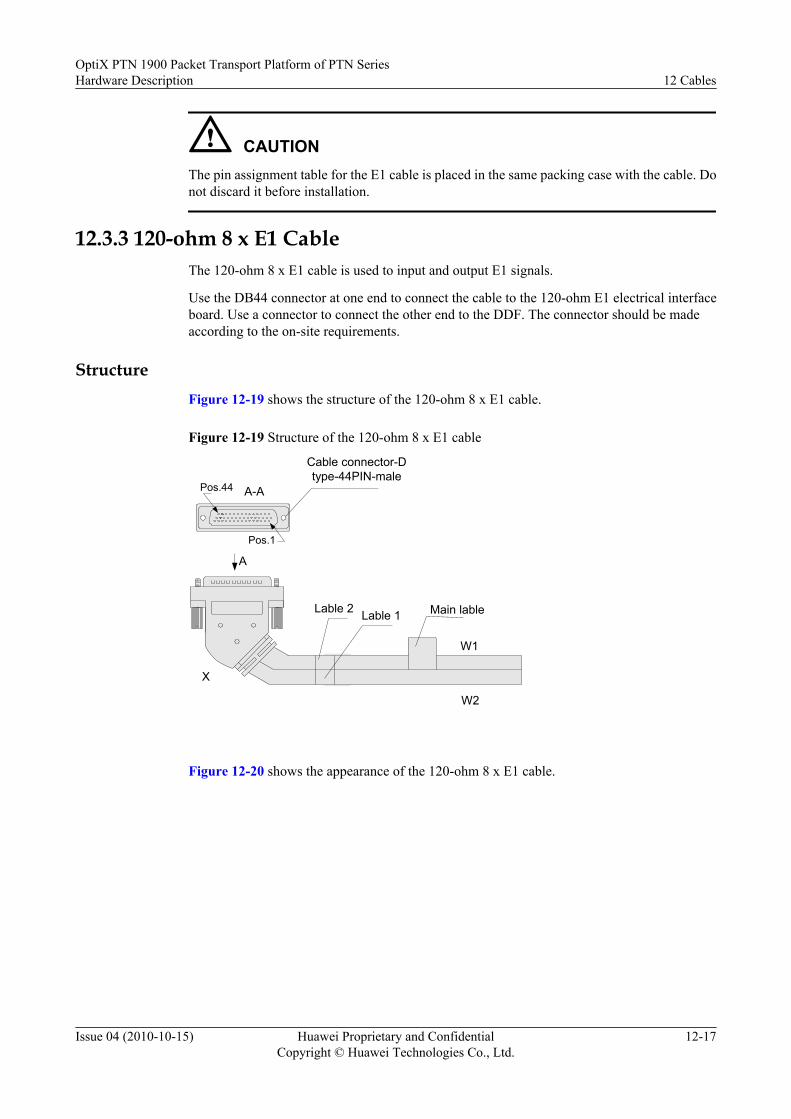
CAUTIONThe pin assignment table for the E1 cable is placed in the same packing case with the cable. Donot discard it before installation.
12.3.3 120-ohm 8 x E1 CableThe 120-ohm 8 x E1 cable is used to input and output E1 signals.
Use the DB44 connector at one end to connect the cable to the 120-ohm E1 electrical interfaceboard. Use a connector to connect the other end to the DDF. The connector should be madeaccording to the on-site requirements.
StructureFigure 12-19 shows the structure of the 120-ohm 8 x E1 cable.
Figure 12-19 Structure of the 120-ohm 8 x E1 cable
Main lable
W1
A
Cable connector-Dtype-44PIN-male
X
Lable 2
W2
Lable 1
Pos.44 A-A
Pos.1
Figure 12-20 shows the appearance of the 120-ohm 8 x E1 cable.
OptiX PTN 1900 Packet Transport Platform of PTN SeriesHardware Description 12 Cables
Issue 04 (2010-10-15) Huawei Proprietary and ConfidentialCopyright © Huawei Technologies Co., Ltd.
12-17

Figure 12-20 Appearance of the 120-ohm 8 x E1 cable
Pin AssignmentTable 12-9 lists the pin assignment of the 120-ohm 8 x E1 cable.
Table 12-9 Pin assignment of the 120-ohm E1 cable
Connectorpin
Cable W1 Remarks
Connector pin
Cable W2 Remarks
Core No. Core No.
15 Blue Twisted pair
T x 1 38 Blue Twistedpair
R x 1
30 White 23 White
14 Orange Twisted pair
T x 2 37 Orange Twistedpair
R x 2
29 White 22 White
13 Green Twisted pair
T x 3 36 Green Twistedpair
R x 3
28 White 21 White
12 Brown Twisted pair
T x 4 35 Brown Twistedpair
R x 4
27 White 20 White
11 Grey Twisted pair
T x 5 34 Grey Twistedpair
R x 5
26 White 19 White
10 Blue Twisted pair
T x 6 33 Blue Twistedpair
R x 6
25 Red 18 Red
9 Orange Twisted pair
T x 7 32 Orange Twistedpair
R x 7
24 Red 17 Red
12 CablesOptiX PTN 1900 Packet Transport Platform of PTN Series
Hardware Description
12-18 Huawei Proprietary and ConfidentialCopyright © Huawei Technologies Co., Ltd.
Issue 04 (2010-10-15)

Connectorpin
Cable W1 Remarks
Connector pin
Cable W2 Remarks
Core No. Core No.
8 Green Twisted pair
T x 8 31 Green Twistedpair
R x 8
7 Red 16 Red
Shell External braid shield layer Shell External braid shield layer
Technical SpecificationsItem Specification
Connector X Cable connector-D type-44PIN-male
Cable type Communication cable-120 ohms-SEYVP-24AWG-16 core-PANTONE 430U
Number of cores 16
Inner conductordiameter
0.4 mm
Fireproof class CM
12.4 Management CableThe management cable includes straight through cable and crossover cable.
12.4.1 Straight Through CableThe straight through cable is used for the communication among the OptiX PTN 1900 equipment,the NMS computer and the Ethernet.
12.4.2 Crossover CableThe crossover cable is used to directly connect the NMS computer to the OptiX PTN 1900equipment.
12.4.1 Straight Through CableThe straight through cable is used for the communication among the OptiX PTN 1900 equipment,the NMS computer and the Ethernet.
For the description of the straight through cable, refer to 12.3.1 Ethernet Cable.
12.4.2 Crossover CableThe crossover cable is used to directly connect the NMS computer to the OptiX PTN 1900equipment.
For the description of the crossover cable, refer to 12.3.1 Ethernet Cable.
OptiX PTN 1900 Packet Transport Platform of PTN SeriesHardware Description 12 Cables
Issue 04 (2010-10-15) Huawei Proprietary and ConfidentialCopyright © Huawei Technologies Co., Ltd.
12-19

12.5 Clock CableThe clock cable includes the 120-ohm clock cable. The clock cable is used to input and outputexternal clock signals.
12.5.1 External Clock CableThe 120-ohm clock cable uses the RJ-45 connector.
12.5.2 Clock Bridging CableOn the OptiX PTN 1900, the 120-to-75-ohm clock cable is used as the clock bridging cable.
12.5.1 External Clock CableThe 120-ohm clock cable uses the RJ-45 connector.
Structure
Figure 12-21 shows the connector structure of the 120-ohm clock cable.
Figure 12-21 Connector structure of the 120-ohm clock cable
PIN #1PIN #8
Pin Assignment
Table 12-10 shows the pin assignment of the cable.
Table 12-10 Pin assignment of the 120-ohm clock cable
Connectorpin
Relation
Description
External ClockMode
External TimeMode(1PPS + TimeInformation )
External TimeMode(DCLS)
1 Twisted pair
Negative receive endof CLK
Unspecified Unspecified
2 Twisted pair
Positive receive endof CLK
Unspecified Unspecified
12 CablesOptiX PTN 1900 Packet Transport Platform of PTN Series
Hardware Description
12-20 Huawei Proprietary and ConfidentialCopyright © Huawei Technologies Co., Ltd.
Issue 04 (2010-10-15)

Connectorpin
Relation
Description
External ClockMode
External TimeMode(1PPS + TimeInformation )
External TimeMode(DCLS)
3 Twisted pair
Unspecified Negative of 1PPSsignals
Negative of DCLSsignals
6 Twisted pair
Unspecified Positive of 1PPSsignals
Positive of DCLSsignals
4 Twisted pair
Negative transmitend of CLK
Grounding end Grounding end
5 Twisted pair
Positive transmit endof CLK
Grounding end Grounding end
7 Twisted pair
Unspecified Negative of timeinformation
Unspecified
8 Twisted pair
Unspecified Positive of timeinformation
Unspecified
Technical SpecificationsItem Specification
Connector of the120-ohm clockcable
Network interface connector-8PIN-8 bit-shielded-crystal modelconnector
12.5.2 Clock Bridging CableOn the OptiX PTN 1900, the 120-to-75-ohm clock cable is used as the clock bridging cable.
StructureFigure 12-22 shows the structure of the 120-to-75-ohm clock bridging cable.
Figure 12-22 Structure of the clock bridging cable
RJ-45 connector
Main label Heat-shrink tube
120-ohm or 75-ohm conversion
connector Label
View A
18
30 m
W1
W2
W3
W4
W5A
X1
Heat-shrink tube
Heat-shrink tube
OptiX PTN 1900 Packet Transport Platform of PTN SeriesHardware Description 12 Cables
Issue 04 (2010-10-15) Huawei Proprietary and ConfidentialCopyright © Huawei Technologies Co., Ltd.
12-21

Pin AssignmentTable 12-11 lists the pin assignment of the clock bridging cable connector.
Table 12-11 Pin assignment of the clock bridging cable connector
120-Ohm Cable 75-OhmCable
ConnectorPin
Color Description Relation Core No.
X1.1 Orange Negative receive end of 120-ohm external clock
Twisted pair W1
X1.2 White Positive receive end of 120-ohm external clock
X1.4 Blue Negative transmit end of 120-ohm external clock
Twisted pair W2
X1.5 White Positive transmit end of 120-ohm external clock
X1.3 Green Unspecified Twisted pair W3
X1.6 White Unspecified
X1.7 White Unspecified Twisted pair W4
X1.8 Brown Unspecified
Technical SpecificationsTable 12-12 lists the technical specifications of the clock bridging cable.
Table 12-12 Technical specifications of the clock bridging cable
Item Specification
Cable Single Cable, 120 ohm To 75 ohm Clock Cable, 30 m, MP8-II,120CC4P0.4P430U(S)+4*SYV75-2/0.34(S)
Connector X1type
Network Interface Connector,8-Bit 8PIN, Crystal Model Connector
120-ohm cabletype
Twisted-Pair Cable, 120 ohm, SEYVP, 0.4 mm, 26AWG, 4Pairs, Pantone430U
75-ohm cabletype
Coaxial Cable, SYV-75-2-2(4.0Z)-1/0.34 mm, OD3.9 mm, Double-LayerCopper Braid Shielded
Cable length 30 m
12 CablesOptiX PTN 1900 Packet Transport Platform of PTN Series
Hardware Description
12-22 Huawei Proprietary and ConfidentialCopyright © Huawei Technologies Co., Ltd.
Issue 04 (2010-10-15)

12.6 Cabinet Indicator CableThe cabinet indicator cable is used to connect the CXP board on the OptiX PTN 1900 and thecabinet indicators. It transmits the indicator signals output by the CXP to the cabinet indicator.
Structure
Figure 12-23 shows the structure of the cabinet indicator cable. Figure 12-24 shows theappearance of the cabinet indicator cable.
Figure 12-23 Structure of the cabinet indicator cable
2
A-A
81
AX1
W
X5
X4
X3
X2B
Label
1B-B
Main labelHeat-shrink tube
Heat-shrink tube
Figure 12-24 Appearance of the cabinet indicator cable
Pin Assignment
Table 12-13 lists the pin assignment of the cabinet indicator cable.
OptiX PTN 1900 Packet Transport Platform of PTN SeriesHardware Description 12 Cables
Issue 04 (2010-10-15) Huawei Proprietary and ConfidentialCopyright © Huawei Technologies Co., Ltd.
12-23

Table 12-13 Pin assignment of the cabinet indicator cable
ConnectorX1
Connector X2/X3/X4/X5 Relation Label Print
X1.4 X2.2 Twistedpair
Green
X1.5 X2.1
X1.1 X3.2 Twistedpair
Red
X1.2 X3.1
X1.3 X4.2 Twistedpair
Orange
X1.6 X4.1
X1.7 X5.2 Twistedpair
Yellow
X1.8 X5.1
Technical Specifications
Item Specification
Connector X1 Network interface connector-8PIN-8 bit-shielded-crystal model connector
Connector X2/X3/X4/X5 Common plug-2PIN-single row/2.5 mm
Cable type Twisted pair cable-120 ohms-SEYPVPV-0.5mm-24AWG-8 core-PANTONE 430U
Number of cores 8
Fireproof class CM
Core diameter 0.5mm
12.7 Alarm Input/Output CableThe alarm input cable is used to input the alarm signals of the external equipment to the OptiXPTN 1900 equipment. The alarm output cable is used to output the alarm signals to the centralalarm monitoring equipment.
One end of the alarm input/output cable uses an RJ-45 connector to connect to the alarm input/output interface of the equipment. The other end uses a connector to connect to the externalequipment or central alarm monitoring equipment. The connector should be made according tothe on-site equipment.
Structure
Figure 12-25 shows the structure of the alarm input/output cable connector.
12 CablesOptiX PTN 1900 Packet Transport Platform of PTN Series
Hardware Description
12-24 Huawei Proprietary and ConfidentialCopyright © Huawei Technologies Co., Ltd.
Issue 04 (2010-10-15)

Figure 12-25 Structure of the alarm input/output cable connector
Pin AssignmentTable 12-14 lists the pin assignment of the alarm input/output cable.
Table 12-14 Pin assignment of the alarm input
Connector
Color Alarm Input
1 White and orange Positive for alarm input 1
2 Orange Negative for alarm input 1
3 White and green Positive for alarm input 2
4 Blue Positive for alarm input 3
5 White and blue Negative for alarm input 3
6 Green Negative for alarm input 2
7 White and brown Positive for alarm input 4
8 Brown Negative for alarm input 4
Technical SpecificationsItem Specification
Connector Network interface connector-8PIN-8 bit-shielded-crystal model connector
OptiX PTN 1900 Packet Transport Platform of PTN SeriesHardware Description 12 Cables
Issue 04 (2010-10-15) Huawei Proprietary and ConfidentialCopyright © Huawei Technologies Co., Ltd.
12-25


A Indicators
This chapter describes the board indicators for the OptiX PTN 1900 and their indications.
A.1 Cabinet IndicatorsThis section describes the ETSI cabinet indicators for the OptiX PTN 1900.
A.2 Board IndicatorsThis section describes the board indicators and their indications.
OptiX PTN 1900 Packet Transport Platform of PTN SeriesHardware Description A Indicators
Issue 04 (2010-10-15) Huawei Proprietary and ConfidentialCopyright © Huawei Technologies Co., Ltd.
A-1

A.1 Cabinet IndicatorsThis section describes the ETSI cabinet indicators for the OptiX PTN 1900.
Indicator Name Description
Power indicator, green, which indicates whetherthe power supply is normal
When the indicator is lit, it indicates thatthe power is supplied to the equipment.
When the indicator is unlit, no power issupplied to the equipment.
Critical alarm indicator, red When the indicator is lit, it indicates thatcritical alarms are generated in theequipment.
When the indicator is unlit, it indicatesthat no critical alarms are generated inthe equipment.
Major alarm indicator, orange When the indicator is lit, it indicates thatmajor alarms are generated in theequipment.
When the indicator is unlit, it indicatesthat no major alarms are generated in theequipment.
Minor alarm indicator, yellow When the indicator is lit, it indicates thatminor alarms are generated in theequipment.
When the indicator is unlit, it indicatesthat no minor alarms are generated in theequipment.
A.2 Board IndicatorsThis section describes the board indicators and their indications.
Index of Indicators
For boards and their indicators, see Boards and Their Indicators.
For board status indicators, see:
l Description of the Working Status Indicator (STAT)l Description of the Service Activation Status and Board Working/Protection Status
Indicator (ACT)l Description of the Working/Protection Status of the Cross-Connect and Timing Board
(ACTX)
A IndicatorsOptiX PTN 1900 Packet Transport Platform of PTN Series
Hardware Description
A-2 Huawei Proprietary and ConfidentialCopyright © Huawei Technologies Co., Ltd.
Issue 04 (2010-10-15)

l Description of the Working/Protection Status of the System Control Board (ACTC)l Description of the Program Status Indicator (PROG)l Description of the Service Status Indicator (SRV)l Description of the Synchronization Status Indicator (SYNC)l Description of the Power Supply Board Fault Indicator (ALM)l Description of the Fan State Indicator(STAT)l Description of the Power Supply Status Indicator (PWR)
For service port status indicators, see:
l Service Port Connection Status Indicator (LINK)l Description of the Service Interface Transmitting/Receiving Status Indicator (ACT)l Description of the Interface Connection and Data Transmitting/Receiving Status
Indicators (L/A)
For system alarm indicators, see:
l Description of the Alarm Cutting Indicator (ALMC)l Description of the Critical Alarm Indicator (CRIT)l Description of the Major Alarm Indicator (MAJ)l Description of the Minor Alarm Indicator (MIN)
For the start status indicator combination in each phase when the service sub-board, and systemcontrol board are started, see Description of the Start Status Indicator Combination on theBoard.
Boards and Their IndicatorsBoard Indicator
MD1 STAT, ACT, SRV
CD1 STAT, ACT, SRV
AD1 STAT, ACT, SRV
ETFC STAT, ACT, SRV, LINK, ACT
EFG2 STAT, ACT, SRV, L/A1, L/A2
EFF8 STAT, ACT, SRV, L/A1 to L/A8
AFO1 STAT, ACT, SRV
POD41 STAT, ACT, SRV
CXP STAT, PROG, SRV, ACTX, ACTC, SYNC
PIU PWR, ALM
FANA CRIT, MAJ, MIN, ALMC, STAT
FANB STAT
OptiX PTN 1900 Packet Transport Platform of PTN SeriesHardware Description A Indicators
Issue 04 (2010-10-15) Huawei Proprietary and ConfidentialCopyright © Huawei Technologies Co., Ltd.
A-3

Description of the Working Status Indicator (STAT)
Status Description
On (green) The board is working normally.
On (red) The board hardware is faulty.
On (orange) The interface board or service sub-board is not loaded with thelogic.
Off l No power is input.l The board is not running.
NOTEIf the logic is loaded to the board but the board is not created, the board cannot be activated. In this case,the STAT indicator is on (green), but the SRV indicator is off.
The description does not involve the STAT indicator on the FANA and FANB. For details on the STATindicator on the FANA and FANB, see Description of the Fan State Indicator(STAT).
Description of the Service Activation Status and Board Working/Protection StatusIndicator (ACT)
Status Description
On (green) l service sub-board are in the active state, and the board isworking.
l The MD1 configured in a TPS protection group is in theworking state.
Off l service sub-board are not activated.l The MD1 configured in a TPS protection group is in the
backup state or protected state.
Description of the Working/Protection Status of the Cross-Connect and TimingBoard (ACTX)
Status Description
On (green) The board is in the working state.
Off The board is in the protection state.
Description of the Working/Protection Status of the System Control Board (ACTC)
Status Description
On (green) The board is in the working state.
A IndicatorsOptiX PTN 1900 Packet Transport Platform of PTN Series
Hardware Description
A-4 Huawei Proprietary and ConfidentialCopyright © Huawei Technologies Co., Ltd.
Issue 04 (2010-10-15)

Status Description
Blinking (green) at 100ms internals
Databases of the equipment are backed up in batch.
Off The board is in the protection state.
CAUTIONWhen the ACT indicator on the protection system control board is flashing, it indicates that the workingsystem control board is backing up databases in batch to the protection system control board. At this time,do not reset the working system control board or remove and then insert the working system control board.Otherwise, the equipment may work abnormally.
Description of the Program Status Indicator (PROG)
Status Description
On (green) l The board software is being initialized.l The board software is normally initialized, and the board
software is running normally.
On (red) l The memory self-check fails.l The board software or the logic file is lost.l Loading of the board software fails.
Blinking (green) at 100ms internals
Loading of the board software is in process.
Blinking (green) at 300ms internals
The BIOS is guiding the upper-layer software.
Blinking (red) at 100 msinternals
The BIOS self-check fails.
Off No power is input.
Description of the Service Status Indicator (SRV)
Status Description
On (green) Services are running normally and no service-related alarmoccurs (including the situation where the board is activated butnot configured with services).
On (red) A critical or major service-related alarm occurs.
On (orange) A minor or remote service-related alarm occurs.
Off l No power is input.l The board is not running.
OptiX PTN 1900 Packet Transport Platform of PTN SeriesHardware Description A Indicators
Issue 04 (2010-10-15) Huawei Proprietary and ConfidentialCopyright © Huawei Technologies Co., Ltd.
A-5

Description of the Synchronization Status Indicator (SYNC)
Status Description
On (green) l The clock works in free-run mode and the system clockpriority list is not configured. By default, the system clockpriority list contains only internal sources.
l The clock works in locked mode and is tracing a clock sourceother than the internal source in the priority list.
l The system clock is working in time synchronization mode,and the PTP time and system clock are in the tracing state.
On (red) l The system clock priority list is configured. All the clocksources, however, are lost except the internal clock sources.The clock works in holdover mode or free-run mode.
l The system clock is working in time synchronization mode,but no synchronization source is available. The system clockand PTP time are working in holdover or free-run mode.
Description of the Power Supply Board Fault Indicator (ALM)
Status Description
On (red) The power supply board is faulty.
Off The power supply board is normal.
Description of the Fan State Indicator(STAT)
Status Description
On (green) The fans are working normally.
On (red) l A fan is faulty.l A fan is working abnormally.
Off The fans are not powered.
Description of the Power Supply Status Indicator (PWR)
Status Description
On (green) The power supply is normal.
Off l The power supply is lost.l The power supply fails.
A IndicatorsOptiX PTN 1900 Packet Transport Platform of PTN Series
Hardware Description
A-6 Huawei Proprietary and ConfidentialCopyright © Huawei Technologies Co., Ltd.
Issue 04 (2010-10-15)
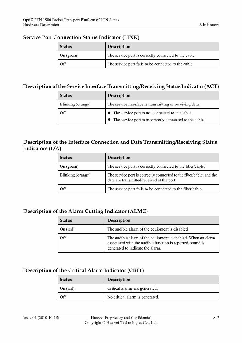
Service Port Connection Status Indicator (LINK)Status Description
On (green) The service port is correctly connected to the cable.
Off The service port fails to be connected to the cable.
Description of the Service Interface Transmitting/Receiving Status Indicator (ACT)Status Description
Blinking (orange) The service interface is transmitting or receiving data.
Off l The service port is not connected to the cable.l The service port is incorrectly connected to the cable.
Description of the Interface Connection and Data Transmitting/Receiving StatusIndicators (L/A)
Status Description
On (green) The service port is correctly connected to the fiber/cable.
Blinking (orange) The service port is correctly connected to the fiber/cable, and thedata are transmitted/received at the port.
Off The service port fails to be connected to the fiber/cable.
Description of the Alarm Cutting Indicator (ALMC)Status Description
On (red) The audible alarm of the equipment is disabled.
Off The audible alarm of the equipment is enabled. When an alarmassociated with the audible function is reported, sound isgenerated to indicate the alarm.
Description of the Critical Alarm Indicator (CRIT)Status Description
On (red) Critical alarms are generated.
Off No critical alarm is generated.
OptiX PTN 1900 Packet Transport Platform of PTN SeriesHardware Description A Indicators
Issue 04 (2010-10-15) Huawei Proprietary and ConfidentialCopyright © Huawei Technologies Co., Ltd.
A-7

Description of the Major Alarm Indicator (MAJ)
Status Description
On (red) Major alarms are generated.
Off No major alarm is generated.
Description of the Minor Alarm Indicator (MIN)
Status Description
On (yellow) Minor alarms are generated.
Off No minor alarm is generated.
Description of the Start Status Indicator Combination on the Board
From power on to normal running, the service sub-board, and system control board go throughvarious statuses. Table A-1 shows the indicator combination corresponding to these statuses.
Table A-1 Start status indicator combination
SN Status Indicator
STAT PROG ACT/ACTC/ACTX
SRV
1 The board is not poweredon.
Off Off Off Off
2 The BIOS is beingstarted.
Off Green Off Off
3 The BIOS is started, andguides and loads theboard software.
Off Blinking(green)
Off Off
4 The upper-layersoftware is beinginitialized.
Green Green Off Off
5 The upper-layersoftware initialization iscomplete, but the boardis not running.
Green Green Off Off
6 The board is running. Green Green Off/Green/Blinking (green)a
Always onb
A IndicatorsOptiX PTN 1900 Packet Transport Platform of PTN Series
Hardware Description
A-8 Huawei Proprietary and ConfidentialCopyright © Huawei Technologies Co., Ltd.
Issue 04 (2010-10-15)

SN Status Indicator
STAT PROG ACT/ACTC/ACTX
SRV
NOTEa: When the board is running, the ACT/ACTC/ACTX indicator may be off, on (green), or flashing (green). When services arenormal, the indicator is on (green). For other statuses, see Description of the Service Activation Status and Board Working/Protection Status Indicator (ACT), Description of the Working/Protection Status of the Cross-Connect and Timing Board(ACTX), and Description of the Working/Protection Status of the System Control Board (ACTC).b: When the board is running, the SRV indicator may be in red, orange, or green. When services are normal, the indicator is green.For other statuses of the indicator, see Description of the Service Status Indicator (SRV).
OptiX PTN 1900 Packet Transport Platform of PTN SeriesHardware Description A Indicators
Issue 04 (2010-10-15) Huawei Proprietary and ConfidentialCopyright © Huawei Technologies Co., Ltd.
A-9


B Labels
On the OptiX PTN 1900, safety labels, optical module labels and engineering labels are stuck.
B.1 Safety LabelVarious safety labels are stuck on the equipment. This section describes positions and indicationsof these safety labels.
B.2 Engineering LabelsThe engineering labels should be made according to the the local engineering specifications orHuawei engineering specifications.
OptiX PTN 1900 Packet Transport Platform of PTN SeriesHardware Description B Labels
Issue 04 (2010-10-15) Huawei Proprietary and ConfidentialCopyright © Huawei Technologies Co., Ltd.
B-1

B.1 Safety LabelVarious safety labels are stuck on the equipment. This section describes positions and indicationsof these safety labels.
B.1.1 LabelsLabels are present on the subrack and boards.
B.1.2 Label PositionSome labels such as the ESD protection label and subrack grounding label are stuck on thesubrack.
B.1.1 LabelsLabels are present on the subrack and boards.
Table B-1 Labels
Label Type Indication
ESD protection label The equipment is electrostatic sensitive.
CLASS 1LASER
PRODUCT
LASERRADIATION
DO NOT VIEW DIRECTLYWITH OPTICALINSTRUMENTSCLASS 1M
LASERPRODUCT
Laser safety class The label indicates the class of the lasersource.
Subrack grounding label This label indicates the groundingposition.
ATTENTION 警告
CLEAN PERIODICALLY 定期清洗
! Regular cleaning label Regularly clean the air filter.
严禁在风扇高速旋转时接触叶片
DON'T TOUCH THEFAN LEAVES BEFORETHEY SLOW DOWN !
Fan warning label Do not touch the fan leaves before the fanstops.
!
Multi-channel powersupply label
Multiple channels of power supply areavailable.
此单元严禁带电插拔!Do not hot plug this unit !
No hot plug label Do not insert or remove the componentwhen the power is on.
B LabelsOptiX PTN 1900 Packet Transport Platform of PTN Series
Hardware Description
B-2 Huawei Proprietary and ConfidentialCopyright © Huawei Technologies Co., Ltd.
Issue 04 (2010-10-15)
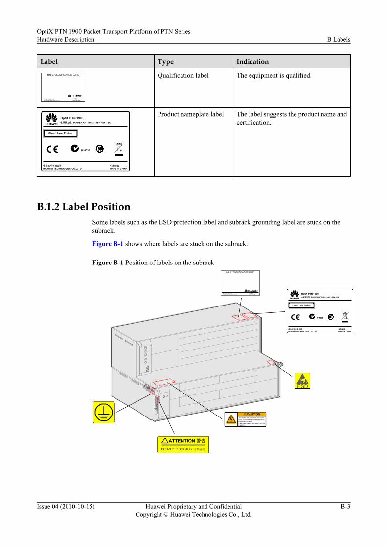
Label Type Indication
合格证/QUALIFICATION CARD
华为技术有限公司 中国制作MADE IN CHINAHUAWEI TECHNOLOGIES CO.,LTD.
HUAWEI
Qualification label The equipment is qualified.
OptiX PTN 1900POWER RATING: -48--60V;12A
华为技术有限公司 中国制造
电源额定值
HUAWEI TECHNOLGIES CO.,LTD. MADE IN CHINA
Class 1 Laser Product
N14036
Product nameplate label The label suggests the product name andcertification.
B.1.2 Label PositionSome labels such as the ESD protection label and subrack grounding label are stuck on thesubrack.
Figure B-1 shows where labels are stuck on the subrack.
Figure B-1 Position of labels on the subrack合格证/QUALIFICATION CARD
华为技术有限公司 中国制造MADE IN CHINAHUAWEI TECHNOLOGIES CO.,LTD.
HUAWEI
ATTENTION 警告
CLEAN PERIODICALLY 定期清洗
!
OptiX PTN 1900POWER RATING: -48--60V;12A
华为技术有限公司 中国制造
电源额定值
HUAWEI TECHNOLGIES CO.,LTD. MADE IN CHINA
Class 1 Laser Product
N14036
OptiX PTN 1900 Packet Transport Platform of PTN SeriesHardware Description B Labels
Issue 04 (2010-10-15) Huawei Proprietary and ConfidentialCopyright © Huawei Technologies Co., Ltd.
B-3

B.2 Engineering LabelsThe engineering labels should be made according to the the local engineering specifications orHuawei engineering specifications.
The engineering labels should be made according to the the local engineering specifications orHuawei engineering specifications. Table B-2 lists the Huawei engineering specifications forengineering labels.
Table B-2 Huawei specifications for engineering labels
Label Illustration Indication
Engineeringlabels forpowercables
(1) (2)
TO: A01 -48V2 B08
TO: B03 -48V2
(1) Label on the cable at the loadedcabinet side, which indicates theposition of the cable at the powerdistribution cabinet side(2) Label on the cable at the powerdistribution cabinet side, whichindicates the position of the cable atthe loaded cabinet side
(1) On the loaded cabinet side, the labelmarked "A01/B08--48V2" on the cableindicates that the cable is used for the-48V2 DC power supply, which comesfrom the eighth connector on the secondrow of the -48 V bus bar in the cabinet onRow A, and Column 01 in the equipmentroom.(2) On the distribution unit side, the labelmarked "B03--48V2" indicates that thecable is -48V2 DC power supply, whichcomes from the loaded cabinet on Row B,Column 03 in the equipment room. ForPGND and BGND, it is only necessary togive the row and column of the powerdistribution unit, instead of the specificserial number of the terminal block on thecopper bar.
Engineeringlabels foralarmexternalcables
The external alarm cables are connected tothe first subscriber cabinet of each row(used for power distribution). Engineeringlabels stuck on the first cabinet of each rowshould indicate which equipment is usingthe access terminal. Engineering labels arenot needed on the equipment side unlessthere are special requirements. The labelmarked "A01" indicates that the alarmcable connects the first cabinet and thecabinet on Row A, Column 01 in theequipment room.
B LabelsOptiX PTN 1900 Packet Transport Platform of PTN Series
Hardware Description
B-4 Huawei Proprietary and ConfidentialCopyright © Huawei Technologies Co., Ltd.
Issue 04 (2010-10-15)

Label Illustration Indication
Engineeringlabels forEthernetcables
"A01-03-06-05" indicates that one end ofthe Ethernet cable is connected to EthernetPort 05, Slot 6, Frame 03 of the cabinet onRow A, Column 01 in the equipment room."B02-03-12" indicates that the other end ofthe Ethernet cable is connected to EthernetPort 12, Frame 03 of the cabinet on RowB, Column 02 in the equipment room. Noslot number is specified.
Engineeringlabels forfibersthatconnectequipment
"A01-01-05-05-R" indicates that the localend of the fiber is connected with OpticalReceiving Interface 05 on Slot 5, Frame 01in the cabinet on Row A, Column 01 in theequipment room. "G01-01-01-01-T"indicates that the opposite end of the fiberis connected with Optical TransmittingInterface 01 on Slot 01, Frame 01 in thecabinet on Row G, Column 01 in theequipment room.
Labelsfor fibersthatconnecttheequipment to theODF
"ODF-G01-01-01-R" indicates that thelocal end of the fiber is connected to theoptical receiving terminal on Row 01,Column 01 of the ODF in Row G Column01 in the equipment room. "A01-01-05-05-R" indicates that the other end of the fiberis connected to optical receiving interface5 on Slot 05, frame 01 in the cabinet onRow A, Column 01 in the equipment room.
Labelsfor trunkcablesthatconnecttheequipment to theODF
"A01-03-01-01-R" indicates that local endof the trunk cable connects to the receivingterminal of Trunk Cable 01 in Slot 01,Frame 03 of the cabinet on Row A, Column01 in the equipment room. "DDF-G01-01-01-AR" indicates that the oppositeend of the trunk cable connects thereceiving terminal of Direction A(connected to optical network equipment)on Row 01, Column 01 of the DDF on RowG and Column 01 in the equipment room.
OptiX PTN 1900 Packet Transport Platform of PTN SeriesHardware Description B Labels
Issue 04 (2010-10-15) Huawei Proprietary and ConfidentialCopyright © Huawei Technologies Co., Ltd.
B-5


C Power Consumption and Weight
This chapter lists the power consumption and weight of each board used for the OptiX PTN1900.
Table C-1 lists the power consumption and weight of each board used for the OptiX PTN1900.
Table C-1 Power consumption and weight
Board Weight (kg) Power Consumption (W)
MD1 0.34 20.7
CD1 0.34 26.4
AD1 0.35 22.0
ETFC 0.55 15.0
EFF8 0.64 16.3
EFG2 0.52 8.8
POD41 0.55 11.6
AFO1 0.78 27.2
L12 0.53 0.1
L75 0.53 0.1
TN71CXP 2.34 73.3
TN72CXP 2.36 80.3
PIU 0.62 7.0
FANA 0.56 l Low rate: 8.0l Medium rate: 12.0l High rate: 21.0
OptiX PTN 1900 Packet Transport Platform of PTN SeriesHardware Description C Power Consumption and Weight
Issue 04 (2010-10-15) Huawei Proprietary and ConfidentialCopyright © Huawei Technologies Co., Ltd.
C-1

Board Weight (kg) Power Consumption (W)
FANB 0.80 l Low rate: 12.0l Medium rate: 19.0l High rate: 35.0
C Power Consumption and WeightOptiX PTN 1900 Packet Transport Platform of PTN Series
Hardware Description
C-2 Huawei Proprietary and ConfidentialCopyright © Huawei Technologies Co., Ltd.
Issue 04 (2010-10-15)

D Board Configuration Parameters
You can use the U2000 to configure each parameter of the processing board, interface board,cross-connect and system control board.
Parameters of the Processing BoardThe configurable parameters of the processing board are the J0, J1, J2, C2, V5, SDH interface,Ethernet interface, automatic laser shutdown (ALS) and spare timeslot recovery value.
l The J0 byte is continually transmitted to carry section access point identifiers, accordingto which the receive end verifies the constant connection to the intended transmit end. It isrecommended to set the J0 byte to "0".
l The J1 byte is the path tracing byte. The transmit end successively transmits the higherorder access point identifiers, according to which the receive end verifies the constantconnection to the intended transmit end. When detecting mismatch of the J1 bytes, thereceive end inserts the HP_TIM alarm in the corresponding path.
l The J2 byte is a VC-12 path tracing byte. The transmit end successively transmits the lowerorder access point identifiers based on the negotiation of the two ends. According to theseaccess point identifiers, the receive end verifies the constant connection to the intendedtransmit end in this path.
l The C2 byte is the signal label byte, which indicates the multiplexing structure of the VCframes and the payload property. The received C2 should be consistent with the transmittedC2. If the C2 bytes are mismatched, the local end inserts the HP_SLM alarm in thecorresponding VC-4 path.Table D-1 lists the mapping relation between the service type and setting of the C2.
Table D-1 Mapping relation between the service type and C2 byte
Input Service Type C2 Byte (in Hex)
TUG structure 02
ATM mapping 13
HDLC, PPP framed signal mapping 16
Unequipped 00
OptiX PTN 1900 Packet Transport Platform of PTN SeriesHardware Description D Board Configuration Parameters
Issue 04 (2010-10-15) Huawei Proprietary and ConfidentialCopyright © Huawei Technologies Co., Ltd.
D-1

l As a path status and signal identification byte, the V5 byte detects the bit error and indicatesthe remote fault and failure in the lower order path. Table D-2 lists the mapping relationbetween the service type and V5 byte.
Table D-2 Mapping relation between the service type and V5 byte
Input Service Type V5 Byte (in Hex)
Asynchronization 02
Unequipped or supervisory unequipped 00
l The attributes of an SDH interface cover the general attributes, Layer 2 attributes, Layer 3
attributes and advanced attributes. To configure an SDH interface, configure the physicalparameters, link layer parameters and network layer parameters.
l The attributes of an Ethernet interface cover the general attributes, Layer 2 attributes, Layer3 attributes, advanced attributes and flow control. To configure an Ethernet interface,configure the physical parameters, link layer parameters, network layer parameters andflow control schemes.
l To configure the ALS is to set the parameters of the optical interface.l To ensure the valid utilization of the path, the spare timeslots are eliminated when the
signals are encapsulated into the network. In this way, the TDM frame is partially stuffed.To recover the TDM frame at the service sink, the spare timeslots eliminated duringencapsulation are added again.
Parameters of the Interface BoardThe configurable parameters of the interface board are the J0, J1, C2, SDH interface, Ethernetinterface, E1 interface, ALS and spare timeslot recovery value.l The attributes of an E1 interface cover the general attributes, Layer 3 attributes and
advanced attributes. To configure an E1 interface, configure the physical parameters,network layer parameters, signal frame format, clock mode and loopback scheme.
l For details on these parameters, see "Parameters of the Processing Board".
Parameters of the Cross-Connect and System Control BoardThe configurable parameters of the CXP board are the environment monitor interface and phase-locked source output by external clock.
You can set the relay control mode and enable or disable the major alarm relay and critical alarmrelay to configure the environment monitor interface.
You can set the output mode, output timeslot, output threshold, failure condition and failureaction of the 2M phase-locked source external clock.
For details, see OptiX PTN 1900 Configuration Guide.
D Board Configuration ParametersOptiX PTN 1900 Packet Transport Platform of PTN Series
Hardware Description
D-2 Huawei Proprietary and ConfidentialCopyright © Huawei Technologies Co., Ltd.
Issue 04 (2010-10-15)

E Glossary
A
Administrator A user who has authority to access all the Management Domains of the EMLCoreproduct. He has access to the whole network and to all the management functionalities.
Alarm A message reported when a fault is detected by a device or by the network managementsystem during the process of polling devices. Each alarm corresponds to a recoveryalarm. After a recovery alarm is received, the status of the corresponding alarm changesto cleared.
alarm cable The cable for generation of visual or audio alarms.
APS See Automatic Protection Switching
AsynchronousTransfer Mode
A data transfer technology based on cell, in which packets allocation relies on channeldemand. It supports fast packet switching to achieve efficient utilization of networkresources. The size of a cell is 53 bytes, which consist of 48-byte payload and 5-byteheader.
ATM See Asynchronous Transfer Mode
Automatic ProtectionSwitching
Automatic Protection Switching (APS) is the capability of a transmission system todetect a failure on a working facility and to switch to a standby facility to recover thetraffic.
B
backup A periodic operation performed on the data stored in the database for the purposes ofdatabase recovery in case that the database is faulty. The backup also refers to datasynchronization between active and standby boards.
bandwidth A range of transmission frequencies that a transmission line or channel can carry in anetwork. In fact, it is the difference between the highest and lowest frequencies thetransmission line or channel. The greater the bandwidth, the faster the data transfer rate.
BER See Bit Error Rate
binding strap The binding strap is 12.7 mm wide, with one hook side (made of transparentpolypropylene material) and one mat side (made of black nylon material).
OptiX PTN 1900 Packet Transport Platform of PTN SeriesHardware Description E Glossary
Issue 04 (2010-10-15) Huawei Proprietary and ConfidentialCopyright © Huawei Technologies Co., Ltd.
E-1

bit error An incompatibility between a bit in a transmitted digital signal and the correspondingbit in the received digital signal.
Bit Error Rate Bit error rate. Ratio of received bits that contain errors. BER is an important index usedto measure the communications quality of a network.
breaker A breaker is a device that connects/disconnects power to a circuit.
bundling An optional multiplexing operation, whereby more than one user message may be carriedin the same SCTP packet.
C
Cable distribution plate A component which is used to arrange the cables in order.
cable tie The tape used to bind the cables.
CE See Customer Edge
CES See Circuit Emulation Service
Circuit EmulationService
A function with which the E1/T1 data can be transmitted through ATM networks. At thetransmission end, the interface module packs timeslot data into ATM cells. These ATMcells are sent to the reception end through the ATM network. At the reception end, theinterface module re-assigns the data in these ATM cells to E1/T1 timeslots. The CEStechnology guarantees that the data in E1/T1 timeslots can be recovered to the originalsequence at the reception end.
client A device that sends requests, receives responses, and obtains services from the server.
Customer Edge A part of BGP/MPLS IP VPN model. It provides interfaces for direct connection to theService Provider (SP) network. A CE can be a router, switch, or host.
D
Data CommunicationNetwork
A communication network used in a TMN or between TMNs to support the DataCommunication Function (DCF).
DCN See Data Communication Network
DDF See Digital Distribution Frame
diamond-shaped nut A type of nut that is used to fasten the wiring frame to the cabinet.
Digital DistributionFrame
A type of equipment used between the transmission equipment and the exchange withtransmission rate of 2 to 155 Mbit/s to provide the functions such as cables connection,cable patching, and test of loops that transmitting digital signals.
E
E-AGGR Ethernet-Aggregation
E-LAN See Ethernet LAN
ejector lever A lever for removing circuit boards from an electronic chassis.
E GlossaryOptiX PTN 1900 Packet Transport Platform of PTN Series
Hardware Description
E-2 Huawei Proprietary and ConfidentialCopyright © Huawei Technologies Co., Ltd.
Issue 04 (2010-10-15)

electromagneticcompatibility
Electromagnetic compatibility is the condition which prevails when telecommunicationsequipment is performing its individually designed function in a common electromagneticenvironment without causing or suffering unacceptable degradation due to unintentionalelectromagnetic interference to or from other equipment in the same environment.[NTIA]
ElectroStatic Discharge The sudden and momentary electric current that flows between two objects at differentelectrical potentials caused by direct contact or induced by an electrostatic field.
EMC See electromagnetic compatibility
ESD See ElectroStatic Discharge
Ethernet A technology complemented in LAN. It adopts Carrier Sense Multiple Access/CollisionDetection. The speed of an Ethernet interface can be 10 Mbit/s, 100 Mbit/s, 1000 Mbit/s or 10000 Mbit/s. The Ethernet network features high reliability and easy maintaining..
Ethernet LAN Ethernet LAN. A L2VPN service type that is provided for the user Ethernet in differentdomains over the PSN network. For the user Ethernet, the entire PSN network serves asa Layer 2 switch.
ETSI See European Telecommunications Standards Institute
EuropeanTelecommunicationsStandards Institute
A standards-setting body in Europe. Also the standards body responsible for GSM.
F
fault A failure to implement the function while the specified operations are performed. A faultdoes not involve the failure caused by preventive maintenance, insufficiency of externalresources and intentional settings.
frame A frame, starting with a header, is a string of bytes with a specified length. Frame lengthis represented by the sampling circle or the total number of bytes sampled during a circle.A header comprises one or a number of bytes with pre-specified values. In other words,a header is a code segment that reflects the distribution (diagram) of the elements pre-specified by the sending and receiving parties.
G
GE See Gigabit Ethernet
Gigabit Ethernet GE adopts the IEEE 802.3z. GE is compatible with 10 Mbit/s and 100 Mbit/s Ethernet.Itruns at 1000Mbit/s. Gigabit Ethernet uses a private medium, and it does not supportcoaxial cables or other cables. It also supports the channels in the bandwidth mode. IfGigabit Ethernet is, however, deployed to be the private bandwidth system with a bridge(switch) or a router as the center, it gives full play to the performance and the bandwidth.In the network structure, Gigabit Ethernet uses full duplex links that are private, causingthe length of the links to be sufficient for backbone applications in a building and campus.
guide rail Components to guide, position, and support plug-in boards.
OptiX PTN 1900 Packet Transport Platform of PTN SeriesHardware Description E Glossary
Issue 04 (2010-10-15) Huawei Proprietary and ConfidentialCopyright © Huawei Technologies Co., Ltd.
E-3

H
hot standby A mechanism of ensuring device running security. The environment variables andstorage information of each running device are synchronized to the standby device. Whenthe faults occur on the running device, the standby device can take over the services inthe faulty device in automatic or manual way to ensure the normal running of the entiresystem.
HSB See hot standby
I
IEC See International Electrotechnical Commission
IEEE See Institute of Electrical and Electronics Engineers
IMA See Inverse Multiplexing over ATM
Institute of Electricaland ElectronicsEngineers
A society of engineering and electronics professionals based in the United States butboasting membership from numerous other countries. The IEEE focuses on electrical,electronics, computer engineering, and science-related matters.
InternationalElectrotechnicalCommission
The International Electrotechnical Commission (IEC) is an international and non-governmental standards organization dealing with electrical and electronical standards.
InternationalTelecommunicationUnion -TelecommunicationStandardization Sector
An organization that coordinates standards for telecommunications on behalf of theInternational Telecommunication Union (ITU). It is based in Geneva, Switzerland. Priorto 1992, the ITU-T was known as the International Telegraph and TelephoneConsultative Committee (CCITT, from the French name "Comit¨| consultatifinternational t¨|l¨|phonique et t¨|l¨|graphique").
Internet Protocol The TCP/IP standard protocol that defines the IP packet as the unit of information sentacross an internet and provides the basis for connectionless, best-effort packet deliveryservice. IP includes the ICMP control and error message protocol as an integral part. Theentire protocol suite is often referred to as TCP/IP because TCP and IP are the twofundamental protocols. IP is standardized in RFC 791.
Inverse Multiplexingover ATM
Inverse Multiplexing over ATM. The ATM inverse multiplexing technique involvesinverse multiplexing and de-multiplexing of ATM cells in a cyclical fashion among linksgrouped to form a higher bandwidth logical link whose rate is approximately the sum ofthe link rates. This is referred to as an IMA group.
IP See Internet Protocol
ITU-T See International Telecommunication Union - Telecommunication StandardizationSector
L
L3VPN Layer3 Virtual Private Network
Label Switching Router The Label Switching Router (LSR) is the basic element of MPLS network. All LSRssupport the MPLS protocol. The LSR is composed of two parts: control unit andforwarding unit. The former is responsible for allocating the label, selecting the route,creating the label forwarding table, creating and removing the label switch path; the latterforwards the labels according to groups received in the label forwarding table.
E GlossaryOptiX PTN 1900 Packet Transport Platform of PTN Series
Hardware Description
E-4 Huawei Proprietary and ConfidentialCopyright © Huawei Technologies Co., Ltd.
Issue 04 (2010-10-15)

LAN See Local Area Network
Laser A component that generates directional optical waves of narrow wavelengths. The laserlight has better coherence than ordinary light. The fiber system takes the semi-conductorlaser as the light source.
LB See Loopback
link A network communications channel consisting of a circuit or transmission path and allrelated equipment between a sender and a receiver. A link is used to connect signalingpoints (SPs) and signaling transfer points (STPs) and transmit signaling messages.
LMSP Linear Multiplex Section Protection
Local Area Network A network formed by the computers and workstations within the coverage of a few squarekilometers or within a single building. It features high speed and low error rate. Ethernet,FDDI, and Token Ring are three technologies used to implement a LAN. Current LANsare generally based on switched Ethernet or Wi-Fi technology and running at 1,000 Mbit/s (that is, 1 Gbit/s).
Loopback A troubleshooting technique that returns a transmitted signal to its source so that thesignal or message can be analyzed for errors.
Lower subrack The subrack close to the bottom of the cabinet when a cabinet contains several subracks.
LSR See Label Switching Router
M
Maintenance Point Maintenance Point (MP) is one of either a MEP or a MIP.
Merge Point Merge Point. The LSR where one or more backup tunnels rejoin the path of the protectedLSP downstream of the potential failure. The same LSR may be both an MP and a PLRsimultaneously.
MP See Merge Point
MP See Maintenance Point
MPLS See Multi-Protocol Label Switch
Multi-Protocol LabelSwitch
A technology that uses short tags of fixed length to encapsulate packets in different linklayers, and provides connection-oriented switching for the network layer on the basis ofIP routing and control protocols. It improves the cost performance and expandability ofnetworks, and is beneficial to routing.
N
N63E cabinet A cabinet which is 600 mm in width and 300 mm in depth, compliant with the standardsof the ETSI.
NE See network element
network element A network element (NE) contains both the hardware and the software running on it. OneNE is at least equipped with one system control board which manages and monitors theentire network element. The NE software runs on the system control board.
Network to NetworkInterface
This is an internal interface within a network linking two or more elements.
OptiX PTN 1900 Packet Transport Platform of PTN SeriesHardware Description E Glossary
Issue 04 (2010-10-15) Huawei Proprietary and ConfidentialCopyright © Huawei Technologies Co., Ltd.
E-5

NNI See Network to Network Interface
O
OAM See Operation, Administration and Maintenanc
ODF See Optical Distribution Frame
Operation,Administration andMaintenanc
Operation, Administration and Maintenance. A group of network support functions thatmonitor and sustain segment operation, activities that are concerned with, but not limitedto, failure detection, notification, location, and repairs that are intended to eliminate faultsand keep a segment in an operational state and support activities required to provide theservices of a subscriber access network to users/subscribers.
Optical DistributionFrame
A frame which is used to transfer and spool fibers.
P
packet 1. A sequence of binary digits including data and call control signals that is switched asa composite whole. The data, call control signals, and possibly error control information,are arra nged in a specific format. 2. A short block of data of fixed length and destinationinformation. It is the information transmission unit of the packet switching network. Themaximum length of the information packet reaches 8000 bit. The information packet canbe tranfered from one metwork to another network. 3. Data packets and local packets.Logical grouping of information that includes a header containing control informationand (usually) user data. Packets are most often used to refer to network layer units ofdata.
Packet over SDH/SONET
A MAN and WAN technology that provides point-to-point data connections. The POSinterface uses SDH/SONET as the physical layer protocol, and supports the transport ofpacket data (such as IP packets) in MAN and WAN.
PCB See Printed Circuit Board
PDU See Power Distribution Unit
PDU Protocol Data Unit
Point-to-Point Protocol A protocol on the data link layer, provides point-to-point transmission and encapsulatesdata packets on the network layer. It is located in layer 2 of the IP protocol stack.
POS See Packet over SDH/SONET
Power DistributionUnit
The power distribution unit performs AC or DC power distribution.
PPP See Point-to-Point Protocol
Printed Circuit Board A board used to mechanically support and electrically connect electronic componentsusing conductive pathways, tracks, or traces, etched from copper sheets laminated ontoa non-conductive substrate.
Pseudo wire An emulated connection between two PEs for transmitting frames. The PW is establishedand maintained by PEs through signaling protocols. The status information of a PW ismaintained by the two end PEs of a PW.
PTN Packet Transport Network
E GlossaryOptiX PTN 1900 Packet Transport Platform of PTN Series
Hardware Description
E-6 Huawei Proprietary and ConfidentialCopyright © Huawei Technologies Co., Ltd.
Issue 04 (2010-10-15)

PW See Pseudo wire
R
Radio NetworkController
A device used in the RNS to control the usage and integrity of radio resources.
RNC See Radio Network Controller
route A route is the path that network traffic takes from its source to its destination. In a TCP/IP network, each IP packet is routed independently. Routes can change dynamically.
S
SDH See Synchronous Digital Hierarchy
signal cable Common signal cables cover the E1cable, network cable, and other non-subscriber signalcable.
Synchronous DigitalHierarchy
SDH is a transmission scheme that follows ITU-T G.707, G.708, and G.709. It definesthe transmission features of digital signals such as frame structure, multiplexing mode,transmission rate level, and interface code. SDH is an important part of ISDN and B-ISDN. It interleaves the bytes of low-speed signals to multiplex the signals to high-speedcounterparts, and the line coding of scrambling is only used only for signals. SDH issuitable for the fiber communication system with high speed and a large capacity sinceit uses synchronous multiplexing and flexible mapping structure.
T
T63 cabinet A cabinet which is 600 mm in width and 300 mm in depth, compliant with the standardsof the ETSI.
TPS See Tributary Protection Switch
Tributary ProtectionSwitch
Tributary protection switching, a function provided by the equipment, is intended toprotect N tributary processing boards through a standby tributary processing board.
Tunnel A channel on the packet switching network that transmits service traffic between PEs.In VPN, a tunnel is an information transmission channel between two entities. The tunnelensures secure and transparent transmission of VPN information. In most cases, a tunnelis an MPLS tunnel.
U
Upload An operation to report some or all configuration data of an NE to the T2000. Theconfiguration data then covers the configuration data stored at the T2000 side.
Upper subrack The subrack close to the top of the cabinet when a cabinet contains several subracks.
upward cabling Cables or fibres connect the cabinet with other equipment from the top of the cabinet.
OptiX PTN 1900 Packet Transport Platform of PTN SeriesHardware Description E Glossary
Issue 04 (2010-10-15) Huawei Proprietary and ConfidentialCopyright © Huawei Technologies Co., Ltd.
E-7

V
Virtual Local AreaNetwork
A logical grouping of two or more nodes which are not necessarily on the same physicalnetwork segment but which share the same IP network number. This is often associatedwith switched Ethernet.
VLAN See Virtual Local Area Network
E GlossaryOptiX PTN 1900 Packet Transport Platform of PTN Series
Hardware Description
E-8 Huawei Proprietary and ConfidentialCopyright © Huawei Technologies Co., Ltd.
Issue 04 (2010-10-15)


![OG for SDH ASON Network Management-(V100R002C01 02)[1]](https://img.pdfslide.us/doc/110x75/553cb1564a7959eb2d8b49f9/og-for-sdh-ason-network-management-v100r002c01-021.jpg)


![OG for RTN End-To-End Management-(V100R002C01 02)[1]](https://img.pdfslide.us/doc/110x75/54e946464a79594d398b4c72/og-for-rtn-end-to-end-management-v100r002c01-021.jpg)
![Administrator Guide-(V100R002C01 06)[1] Copy](https://img.pdfslide.us/doc/110x75/544e6038b1af9f2f638b4e1a/administrator-guide-v100r002c01-061-copy.jpg)