Embed Size (px)
Citation preview

OPTIWAVE 7300 COPTIWAVE 7300 COPTIWAVE 7300 COPTIWAVE 7300 C Technical DatasheetTechnical DatasheetTechnical DatasheetTechnical Datasheet
Non-contact Radar (FMCW) Level Meter for Liquids
• One converter for all antenna types (PTFE Drop, PP Drop and metallic horn)• The only guarantee for measuring accurately in difficult conditions - even in tanks
with agitated surfaces, foam or internal objects• Unique Drop antenna option operates in process conditions with heavy
condensation and prevents product build up
© KROHNE 05/2009 - 4000112304 - TD OPTIWAVE 7300 R09 en
TD_OPTIWAVE7300_en_090529_4000112304_R09_web.book Page 1 Thursday, June 4, 2009 8:44 AM

CONTENTS
2 www.krohne.com 05/2009 - 4000112304 - TD OPTIWAVE 7300 R09 en
OPTIWAVE 7300 C
1 Product features 3
1.1 The radar solution for liquids........................................................................................... 31.2 Applications ...................................................................................................................... 51.3 Measuring principle.......................................................................................................... 7
2 Technical data 8
2.1 Technical data................................................................................................................... 82.2 Antenna selection........................................................................................................... 122.3 Dimensions and weights ................................................................................................ 13
3 Installation 20
3.1 Intended use ................................................................................................................... 203.2 Pre-installation requirements ....................................................................................... 203.3 How to prepare the tank before you install the device.................................................. 21
3.3.1 Theoretical data for nozzle position ..................................................................................... 213.4 Installation recommendations for liquids...................................................................... 23
3.4.1 General requirements .......................................................................................................... 233.4.2 Installation in stilling wells................................................................................................... 233.4.3 Bypass chambers.................................................................................................................. 27
3.5 How to install the device on the tank ............................................................................. 293.5.1 How to install a device with a flange connection ................................................................. 293.5.2 How to install a device with a threaded connection ............................................................. 29
4 Electrical connections 30
4.1 Safety instructions.......................................................................................................... 304.2 Electrical installation: outputs 1 and 2 .......................................................................... 30
4.2.1 Non-Ex................................................................................................................................... 314.2.2 Ex i ......................................................................................................................................... 314.2.3 Ex d ........................................................................................................................................ 31
4.3 Protection category ........................................................................................................ 324.4 Networks ........................................................................................................................ 33
4.4.1 General information.............................................................................................................. 334.4.2 Point-to-point connection..................................................................................................... 334.4.3 Multi-drop networks ............................................................................................................. 34
5 Order form 35
5.1 Device data ..................................................................................................................... 355.2 Rating data...................................................................................................................... 355.3 Contact data.................................................................................................................... 36
6 Notes 37
TD_OPTIWAVE7300_en_090529_4000112304_R09_web.book Page 2 Thursday, June 4, 2009 8:44 AM

PRODUCT FEATURES 1
3
OPTIWAVE 7300 C
www.krohne.com05/2009 - 4000112304 - TD OPTIWAVE 7300 R09 en
Product features
1.1 The radar solution for liquids
This device is a non-contact Radar (FMCW) Level Meter for distance, level and volume measurement of liquids, pastes and slurries. It gives a stabler measurement than pulse radar and is well suited to agitated process conditions. The device can operate at very low and very high process temperatures as long as the process connection temperature limits are observed.
1 Optional touch screen with 4-button operation2 2-wire level meter3 One converter for all applications4 Stainless steel horn or PTFE/PP Drop antenna5 Antenna extension (for long nozzles)6 Optional Metaglas® barrier7 Rotatable housing8 Same housing for Ex d and non-Ex
TD_OPTIWAVE7300_en_090529_4000112304_R09_web.book Page 3 Thursday, June 4, 2009 8:44 AM

1 PRODUCT FEATURES
4
OPTIWAVE 7300 C
www.krohne.com 05/2009 - 4000112304 - TD OPTIWAVE 7300 R09 en
Highlights• ±3 mm / ±0.12¨ standard accuracy• Optionally equipped with a 4-button touch screen display and an easy-to-use setup wizard• Reliable measurement in difficult process conditions• Operates up to a process connection temperature of 200°C / 390°F and 40 bar / 580 psig• Measuring range up to 80 m / 260 ft• Long antenna versions can be extended to suit any nozzle length• Drop antenna for corrosive liquids (with optional PTFE/PP flange plate) or where product
build-up is likely to occur• Sealed Drop antenna extension option for pressurized tanks• PACTware and DTMs included as standard• Optional second current output• Directly-accessible graphic touchscreen/wizard (option)• Converter rotates 360°• Triple barrier gas-tight protection available for working with dangerous gases
(using pre-stressed fused glass)
Industries• Chemicals• Food & Beverage• Oil & Gas • Petrochemicals• Pulp & Paper • Water & Wastewater
Applications• Tanks with agitators• Process tanks• Storage tanks
TD_OPTIWAVE7300_en_090529_4000112304_R09_web.book Page 4 Thursday, June 4, 2009 8:44 AM

PRODUCT FEATURES 1
5
OPTIWAVE 7300 C
www.krohne.com05/2009 - 4000112304 - TD OPTIWAVE 7300 R09 en
1.2 Applications
1. Level measurement of liquids in storage tanks
2. Level measurement of liquids in process tanks
3. Open channel metering or flow
The level transmitter can measure the level of a wide range of liquid products on a large variety of installations, including LPG and LNG tanks. It does not require calibration or commissioning when installed. It can measure any liquid within the stated pressure and temperature range, and distances up to 80 m / 260 ft.
The level transmitter can measure level accurately in agitated conditions, such as near to vortexes caused by agitators, and also where foam is present.
The level transmitter can measure level in an open channel and convert this measurement into flow values if the characteristics of the channel are known. This solution is the high end alternative to ultrasonic and hydrostatic pressure transmitters.
TD_OPTIWAVE7300_en_090529_4000112304_R09_web.book Page 5 Thursday, June 4, 2009 8:44 AM

1 PRODUCT FEATURES
6
OPTIWAVE 7300 C
www.krohne.com 05/2009 - 4000112304 - TD OPTIWAVE 7300 R09 en
4. Measurement of liquids in a bypass chamber
5. Measurement of corrosive liquids with a Drop antenna
If the tank is full of obstructions such as agitators and reinforcements, we recommend installing the radar level transmitter in a bypass chamber or a stilling well. This solution is also available from us under the name BM 26 W. The BM 26 W combines the BM 26 A with the radar level transmitter. The device includes a permanent, local indication without a power supply. Please refer to the BM 26 W documentation for further information.
The Drop antenna option combines a relatively small radar beam for more precise measurement and a shape that avoids product build-up. If the tank contains corrosive liquids such as acids and alkaline solutions, we recommend the DN80 / 3¨ Drop antenna with the PTFE or PP flange plate option.
TD_OPTIWAVE7300_en_090529_4000112304_R09_web.book Page 6 Thursday, June 4, 2009 8:44 AM
PRODUCT FEATURES 1
7
OPTIWAVE 7300 C
www.krohne.com05/2009 - 4000112304 - TD OPTIWAVE 7300 R09 en
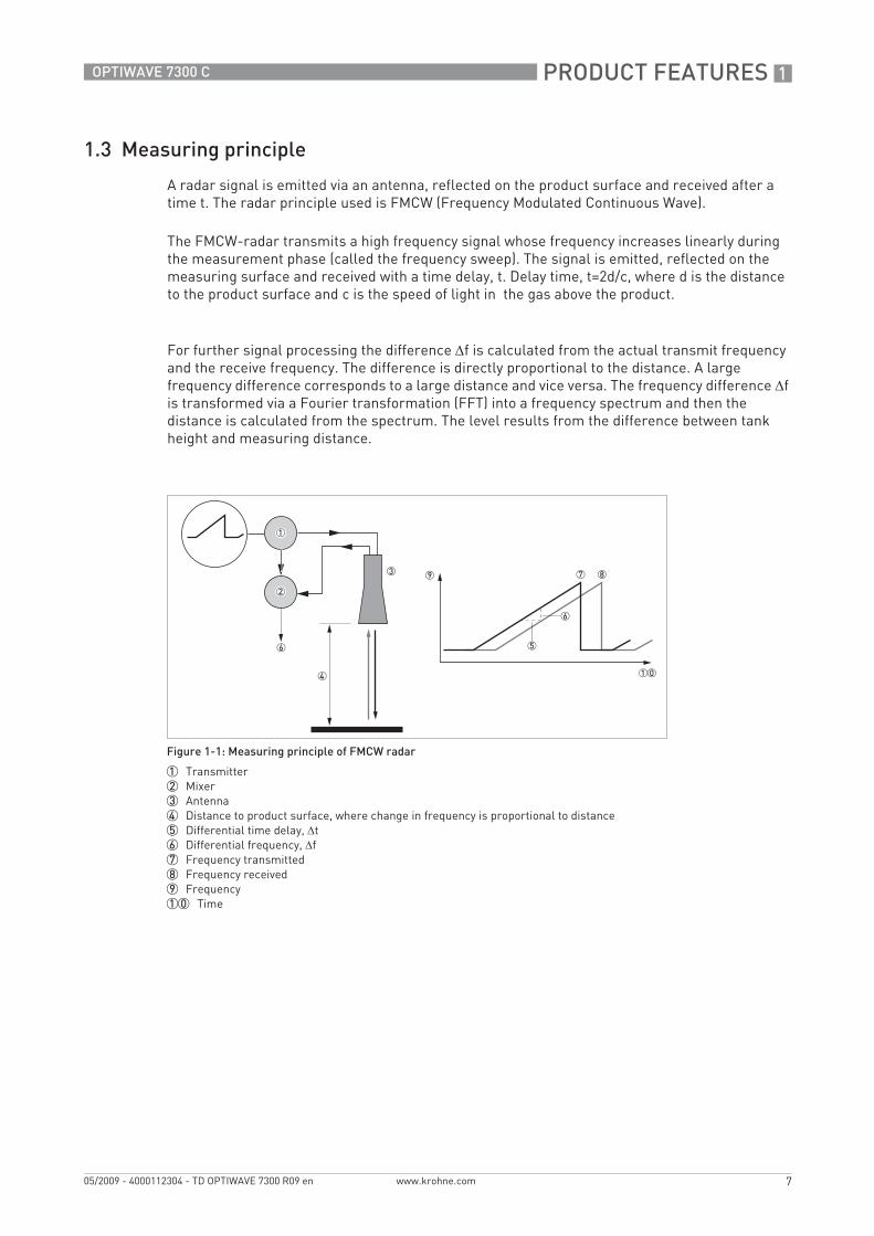
1.3 Measuring principle
A radar signal is emitted via an antenna, reflected on the product surface and received after a time t. The radar principle used is FMCW (Frequency Modulated Continuous Wave).
The FMCW-radar transmits a high frequency signal whose frequency increases linearly during the measurement phase (called the frequency sweep). The signal is emitted, reflected on the measuring surface and received with a time delay, t. Delay time, t=2d/c, where d is the distance to the product surface and c is the speed of light in the gas above the product.
For further signal processing the difference Δf is calculated from the actual transmit frequency and the receive frequency. The difference is directly proportional to the distance. A large frequency difference corresponds to a large distance and vice versa. The frequency difference Δf is transformed via a Fourier transformation (FFT) into a frequency spectrum and then the distance is calculated from the spectrum. The level results from the difference between tank height and measuring distance.
Figure 1-1: Measuring principle of FMCW radar
1 Transmitter2 Mixer3 Antenna4 Distance to product surface, where change in frequency is proportional to distance5 Differential time delay, Δt6 Differential frequency, Δf7 Frequency transmitted8 Frequency received9 Frequency10 Time
TD_OPTIWAVE7300_en_090529_4000112304_R09_web.book Page 7 Thursday, June 4, 2009 8:44 AM

2 TECHNICAL DATA
8
OPTIWAVE 7300 C
www.krohne.com 05/2009 - 4000112304 - TD OPTIWAVE 7300 R09 en
Technical data
2.1 Technical data
• The following data is provided for general applications. If you require data that is more relevant to your specific application, please contact us or your local representative.
• Additional information (certificates, special tools, software,...) and complete product documentation can be downloaded free of charge from the website (Downloadcenter).
Measuring systemMeasuring principle 2-wire loop-powered level transmitter; K-band FMCW radar
Application range Level measurement of liquids, pastes and slurries
Primary measured value Δf (change in frequency) between the emitted and received signal
Secondary measured value Distance, level, volume and reflectivity
DesignConstruction The measurement system consists of a measuring sensor (antenna) and a signal
converter which is only available in a compact version
Options Integrated LCD display with sun cover (-20..+60°C / -4…+140°F); if the ambient temperature is not in these limits, the display switches off
2nd current output
PTFE/PP flange plate protection (for Drop antennas without antenna extensions only)
Antenna purging system for horn antenna (supplied with ¼ NPTF connection)
Accessories Weather protection
Antenna extensions of 105 mm / 4.1¨ length (Max length for Drop antenna versions: 525 mm / 20.7¨)
Max. measuring range 80 m / 260 ft
Depends on the antenna option, dielectric constant of the product and installation type. Refer also to "Antenna selection".
Min. tank height 0.2 m / 8¨
Dead zone Antenna extension length + antenna length + 0.1 m / 4¨
Beam angle of antenna Horn DN40 / 1.5¨: 20°
Horn DN50 / 2¨: 15°
Horn DN80 / 3¨: 10°
Horn DN100 / 4¨: 8°
Drop DN80 / 3¨: 8°
Display and user interfaceDisplay and user interfaceDisplay and user interfaceDisplay and user interface
Display LCD display
9 lines, 160 x 160 pixels in 8-step greyscale with 4-button keypad
Interface languages English, German, French, Italian, Spanish, Portuguese, Japanese, Chinese (Mandarin) and Russian
TD_OPTIWAVE7300_en_090529_4000112304_R09_web.book Page 8 Thursday, June 4, 2009 8:44 AM

TECHNICAL DATA 2
9
OPTIWAVE 7300 C
www.krohne.com05/2009 - 4000112304 - TD OPTIWAVE 7300 R09 en
Measuring accuracyResolution 1 mm / 0.04¨
Repeatability ±1 mm / ±0.04¨
Accuracy ±3 mm / ±0.12¨, when distance < 10 m / 33 ft;±0.03% of measured distance, when distance > 10 m / 33 ft
Reference conditions acc. to EN 60770Reference conditions acc. to EN 60770Reference conditions acc. to EN 60770Reference conditions acc. to EN 60770
Temperature +20°C ±5°C / +70°F ±10°F
Pressure 1013 mbar abs. ±20 mbar / 14.69 psig ±0.29 psig
Relative air humidity 60% ±15%
Target Metal plate in an anechoic chamber
Operating conditionsTemperatureTemperatureTemperatureTemperature
Ambient temperature -40…+80°C / -40…+175°F (according to the temperature limits of the gasket material. Refer to "Materials" in this table.)Ex i: see supplementary operating instructions or approval certificates
Storage temperature -40…+85°C / -40…+185°F
Process connection temperature Horn antenna:Horn antenna:Horn antenna:Horn antenna:-40…+200°C / -40…+390°F (according to the temperature limits of the gasket material. Refer to "Materials" in this table.)Ex i: see supplementary operating instructions or approval certificates
Drop antenna (PTFE):Drop antenna (PTFE):Drop antenna (PTFE):Drop antenna (PTFE):-40…+150°C / -58…+300°F (according to the temperature limits of the gasket material. Refer to "Materials" in this table.)Ex i: see supplementary operating instructions or approval certificates
Drop antenna (PP):Drop antenna (PP):Drop antenna (PP):Drop antenna (PP):-40…+100°C / -40…+210°F (according to the temperature limits of the gasket material. Refer to "Materials" in this table.)Ex i: see supplementary operating instructions or approval certificates
Thermal shock resistance <40°C/s / <72°F/s
PressurePressurePressurePressure
Operating pressure Drop antenna (PP):Drop antenna (PP):Drop antenna (PP):Drop antenna (PP): -1…16 bar / -14.5…232 psig;subject to process connection used and flange temperature
All other antennas:All other antennas:All other antennas:All other antennas:-1…40 bar / -14.5…580 psig;subject to process connection used and flange temperature
Other conditionsOther conditionsOther conditionsOther conditions
Dielectric constant (εr) ≥1.5
Vibration resistance IEC 60068-2-6 and EN 50178 (10...57 Hz: 0.075 mm / 57...150 Hz:1g)
Protection category IP 66/67 equivalent to NEMA 6-6X
TD_OPTIWAVE7300_en_090529_4000112304_R09_web.book Page 9 Thursday, June 4, 2009 8:44 AM

2 TECHNICAL DATA
10
OPTIWAVE 7300 C
www.krohne.com 05/2009 - 4000112304 - TD OPTIWAVE 7300 R09 en
Installation conditionsProcess connection size The process connection should be larger than the antenna diameter.
If the process connection on the device is smaller than the antenna, either:- provide the means to adapt the device to a larger process connection on the tank (for example, a plate with a slot), or- use the same process connection, but remove the antenna from the device before installation and fit it from inside the tank.
Process connection position Make sure that there are not any obstructions directly below the process connection for the device.
Dimensions and weights Refer to "Technical data: Dimensions and weights"
MaterialsHousing Standard: Aluminium
Option: Stainless steel (1.4404 / 316 L)
Wetted parts, including antenna Standard for Horn antenna: Stainless steel (1.4404 / 316L)
Option for Horn antenna: Hastelloy® C-22 (2.4602) 1
Drop antenna: PTFE; PP - a PP or PTFE flange plate option is also available
Process fitting Standard: Stainless steel (1.4404 / 316L) - a PP or PTFE flange plate option is also available for Drop antenna
Option: Hastelloy® C-22 (2.4602)
Gaskets (and o-rings for the sealed antenna extension option)
FKM/FPM (-40…+200°C / -40…+390°F); Kalrez® 6375 (-20…+200°C / -4…+390°F);EPDM (-40°C…+150°C / -40…+300°F) 2
Feedthrough Standard: PEI (-40...+200°C / -40...+390°F)
Option: Metaglas® (-30...+200°C / -22...+390°F - for horn antennas only) 3
Weather protection (Option) Stainless steel (1.4301 / 304)
Process connectionsThread G 1½; 1½ NPT
Flange versionFlange versionFlange versionFlange version
EN DN40…150 in PN40 / PN16; others on request
ASME 1½¨…8¨ in 150 lbs / 300 lbs; others on request
JIS 40…100A in 10K; others on request
Electrical connectionsPower supply Terminals output 1 - Non-Ex / Ex i:Terminals output 1 - Non-Ex / Ex i:Terminals output 1 - Non-Ex / Ex i:Terminals output 1 - Non-Ex / Ex i:
14…30 VDC; min./max. value for an output of 22 mA at the terminal
Terminals output 1 - Ex d:Terminals output 1 - Ex d:Terminals output 1 - Ex d:Terminals output 1 - Ex d:20…36 VDC; min./max. value for an output of 22 mA at the terminal
Terminals output 2 - Non-Ex/ Ex i/ Ex d:Terminals output 2 - Non-Ex/ Ex i/ Ex d:Terminals output 2 - Non-Ex/ Ex i/ Ex d:Terminals output 2 - Non-Ex/ Ex i/ Ex d:10…30 VDC; min./max. value for an output of 22 mA at the terminal (additional power supply needed - output only)
Cable entry M20x1.5; ½NPT
G ½ (not for FM- and CSA-approved devices)
M25x1.5 (for stainless steel housings only)
Cable gland Standard: none
Options: M20x1.5 (for non-Ex and Ex -approved devices with M20x1.5 and M25x1.5 cable entries); others are available on request
Cable entry capacity (terminal) 0.5…1.5 mm²
TD_OPTIWAVE7300_en_090529_4000112304_R09_web.book Page 10 Thursday, June 4, 2009 8:44 AM

TECHNICAL DATA 2
11
OPTIWAVE 7300 C
www.krohne.com05/2009 - 4000112304 - TD OPTIWAVE 7300 R09 en
Input and outputOutput signal(Output 1)
4…20 mA HART® or 3.8…20.5 mA acc. to NAMUR NE 43 4
Output signal(Output 2 - optional)
4…20 mA (no HART® signal) or 3.8…20.5 mA acc. to NAMUR NE 43
Resolution ±3 µA
Temperature drift Typically 50 ppm/K
Error signal High: 22 mA; Low: 3.6 mA acc. to NAMUR NE 43
Approvals and certificationCE This device fufills the statutory requirements of the EC directives. The
manufacturer certifies successful testing of the product by applying the CE mark.
Explosion protectionExplosion protectionExplosion protectionExplosion protection
ATEX ATEX II G 1, 1/2, 2 Ex ia IIC T6...T3;
ATEX II D 1, 1/2, 2 Ex iaD 20 or Ex iaD 20/21 or Ex iaD 21 IP6X T65°C...T90°C;
ATEX II G 1/2, 2 Ex d [ia] IIC T6...T3;
ATEX II D 1/2, 2 Ex tD[iaD] A21/20 or Ex tD[iaD] A21 IP6X T65°C...T90°C;
ATEX II G 3 Ex nA IIC T6…T3
IECEx (approval for Drop antennas pending)
Zone 0 Ex ia IIC T6…T3; Ex iaD 20 IP6X T65°C…T 90°C
FM or CSA - Dual Seal-approved (approval for Drop antennas pending)
NEC 500/ CEC:NEC 500/ CEC:NEC 500/ CEC:NEC 500/ CEC:
Cl. I, Div. 1, Gr. ABCD (IS);
Cl. I, Div. 1, Gr. ABCD (FM only) (XP);
Cl. I, Div. 2, Gr. ABCD (XP/NI);
Cl. II, Div. 1, Gr. EFG; Cl. III (FM only) (XP);
Cl. II, Div. 1, Gr. EFG; Cl. III (IS);
Cl. II/III, Div. 2, Gr. FG (XP/NI)
NEC 505/ CEC:NEC 505/ CEC:NEC 505/ CEC:NEC 505/ CEC:
Cl. I, Zone 0 AEx ia Gr. IIC (CSA: Ex ia) (IS);
Cl. I, Zone 1 AEx d [ia] Gr. IIC (XP);
Cl. I, Zone 2 AEx nA [ia] Gr. IIC (CSA: Ex nA [ia]) (IS)
NEPSI (approval for Drop antennas pending)
Ex dia IIC T3…T6; Ex ia IIC T3…T6
WHG (approval for Drop antennas pending)
Certificate Z-65.16-425. In conformity with the German Federal Water Act, §9
Other standards and approvalsOther standards and approvalsOther standards and approvalsOther standards and approvals
EMC EMC Directives 2004 / 108 / EC and 93 / 68 / EEC in conjunction with EN 61326-1 (2006).
LVD Low-Voltage Directives 2006 / 95 / EC and 93 / 68 / EEC in conjunction with EN 61010-1 (2001).
NAMUR NAMUR NE 21 Electromagnetic Compatibility (EMC) of Industrial Process and Laboratory Control Equipment
NAMUR NE 43 Standardization of the Signal Level for the Failure Information of Digital Transmitters
1 Hastelloy® is a registered trademark of Haynes International, Inc.2 Kalrez® is a registered trademark of DuPont Performance Elastomers L.L.C.3 Metaglas® is a registered trademark of Herberts Industrieglas, GMBH & Co., KG4 HART® is a registered trademark of the HART Communication Foundation
TD_OPTIWAVE7300_en_090529_4000112304_R09_web.book Page 11 Thursday, June 4, 2009 8:44 AM

2 TECHNICAL DATA
12
OPTIWAVE 7300 C
www.krohne.com 05/2009 - 4000112304 - TD OPTIWAVE 7300 R09 en
2.2 Antenna selection
The graphs below show which antenna to select for the application based on:• D, the measuring range,• εr, is the dielectric constant of the product being measured
Figure 2-1: Selection of antenna for liquid applications (graph of distance in m against εr)
Figure 2-2: Selection of antenna for liquid applications (graph of distance in ft against εr)
1 Distance, D [m]2 Distance, D [ft]3 Dielectric constant (εr) range for storage/stillwell applications4 Dielectric constant (εr) range for process/agitator applications5 DN 80 or DN 100 horn antenna in a still well6 DN 80 or DN 100 horn antenna with or without a still well, or DN 80 Drop antenna without a still well7 DN40, DN 50, DN 80 or DN 100 horn antenna with or without a still well, or DN 80 Drop antenna without a still well
TD_OPTIWAVE7300_en_090529_4000112304_R09_web.book Page 12 Thursday, June 4, 2009 8:44 AM

TECHNICAL DATA 2
13
OPTIWAVE 7300 C
www.krohne.com05/2009 - 4000112304 - TD OPTIWAVE 7300 R09 en
2.3 Dimensions and weights
Dimensions and weights in mm and kg
Dimensions and weights in inches and lbs
Housing
Figure 2-3: Housing dimensions
1 Housing front view2 Housing side view
Dimensions [mm] Weights [kg]
a b c d e f g
Housing 180 122 158.5 182 1 167 277 155 3.3
1 if fitted with standard cable glands
Dimensions [inches] Weights [lbs]
a b c d e f g
Housing 7.1 4.8 6.2 7.2 1 6.5 10.9 6.1 7.3
1 if fitted with standard cable glands
• Cable glands are delivered on demand with non-Ex, Ex i- and Ex d-approved devices.• The diameter of the outer sheath of the cable must be 6…12 mm or 0.2…0.5¨.• Cable glands for FM- or CSA-approved devices must be supplied by the customer.• A weather protection cover is available on request with all devices.
TD_OPTIWAVE7300_en_090529_4000112304_R09_web.book Page 13 Thursday, June 4, 2009 8:44 AM

2 TECHNICAL DATA
14
OPTIWAVE 7300 C
www.krohne.com 05/2009 - 4000112304 - TD OPTIWAVE 7300 R09 en
Dimensions and weights in mm and kg
Dimensions and weights in inches and lbs
Weather protection
Figure 2-4: Dimensions of the weather protection option
1 Weather protection, back view2 Weather protection, left side view
Dimensions [mm] Weights [kg]
a b c d
Weather protection
208 231.5 268 1 66 2.9
1 radius
Dimensions [inches] Weights [lbs]
a b c d
Weather protection
8.2 9.1 10.6 1 2.6 6.4
1 radius
TD_OPTIWAVE7300_en_090529_4000112304_R09_web.book Page 14 Thursday, June 4, 2009 8:44 AM

TECHNICAL DATA 2
15
OPTIWAVE 7300 C
www.krohne.com05/2009 - 4000112304 - TD OPTIWAVE 7300 R09 en
Dimensions and weights in mm and kg
Dimensions and weights in inches and lbs
DN40 or 1.5¨ horn antenna versions
Figure 2-5: DN40 or 1.5¨ horn antenna versions
1 DN40 or 1.5¨ horn antenna with G1½ or 1½NPT thread connection2 DN40 or 1.5¨ horn antenna with flange connection
Dimensions [mm] Weights [kg]
a b c d e f h Øi
Thread connection
194 1 170 201 233 359 32 126 2 39 6
Flange connection
194 1 170 201 246 342 45 96 2 39 8
1 if fitted with standard cable glands2 additional antenna extensions of Ø39 x length 105 mm are available
Dimensions [inches] Weights [lbs]
a b c d e f h Øi
Thread connection
7.6 1 6.7 7.9 9.2 14.1 1.3 4.9 2 1.5 13.2
Flange connection
7.6 1 6.7 7.9 9.7 13.5 1.8 3.8 2 1.5 17.6
1 if fitted with standard cable glands2 additional antenna extensions of Ø1.5 x length 4.1¨ are available
TD_OPTIWAVE7300_en_090529_4000112304_R09_web.book Page 15 Thursday, June 4, 2009 8:44 AM

2 TECHNICAL DATA
16
OPTIWAVE 7300 C
www.krohne.com 05/2009 - 4000112304 - TD OPTIWAVE 7300 R09 en
Dimensions and weights in mm and kg
Dimensions and weights in inches and lbs
DN50 or 2¨ horn antenna versions
Figure 2-6: DN50 or 2¨ horn antenna versions
1 DN50 or 2¨ horn antenna with G1½ or 1½NPT thread connection2 DN50 or 2¨ horn antenna with flange connection
Dimensions [mm] Weight [kg]
a b c d e f h Øi
Thread connection
182 1 167 201 234 370 32 136 2 43 6
Flange connection
182 1 167 201 246 353 45 107 2 43 8
1 if fitted with standard cable glands2 additional antenna extensions of Ø39 x length 105 mm are available
Dimensions [inches] Weights [lbs]
a b c d e f h Øi
Thread connection
7.2 1 6.5 7.9 9.2 14.5 1.3 5.3 2 1.7 13.2
Flange connection
7.2 1 6.5 7.9 9.7 13.9 1.8 4.2 2 1.7 17.6
1 if fitted with standard cable glands2 additional antenna extensions of Ø1.5 x length 4.1¨ are available
TD_OPTIWAVE7300_en_090529_4000112304_R09_web.book Page 16 Thursday, June 4, 2009 8:44 AM

TECHNICAL DATA 2
17
OPTIWAVE 7300 C
www.krohne.com05/2009 - 4000112304 - TD OPTIWAVE 7300 R09 en
Dimensions and weights in mm and kg
Dimensions and weights in inches and lbs
DN80/3¨ horn antenna versions
Figure 2-7: DN80/3¨ horn antenna versions
1 DN80/3¨ horn antenna with G1½ or 1½NPT thread connection2 DN80/3¨ horn antenna with flange connection
Dimensions [mm] Weights [kg]
a b c d e f h Øi
Thread connection
182 1 167 201 233 479 32 246 2 75 5.5
Flange connection
182 1 167 201 246 463 45 217 2 75 6.9…26.2
1 if fitted with standard cable glands2 additional antenna extensions of Ø39 x length 105 mm are available
Dimensions [inches] Weights [lbs]
a b c d e f h Øi
Thread connection
7.2 1 6.5 7.9 9.2 18.9 1.3 9.7 2 3 12.1
Flange connection
7.2 1 6.5 7.9 9.7 18.2 1.8 8.5 2 3 15.2…57.8
1 if fitted with standard cable glands2 additional antenna extensions of Ø1.5 x length 4.1¨ are available
TD_OPTIWAVE7300_en_090529_4000112304_R09_web.book Page 17 Thursday, June 4, 2009 8:44 AM

2 TECHNICAL DATA
18
OPTIWAVE 7300 C
www.krohne.com 05/2009 - 4000112304 - TD OPTIWAVE 7300 R09 en
Dimensions and weights in mm and kg
Dimensions and weights in inches and lbs
DN100/4¨ horn antenna versions
Figure 2-8: DN100/4¨ horn antenna versions
1 DN100/4¨ horn antenna with G1½ or 1½NPT thread connection2 DN100/4¨ horn antenna with flange connection
Dimensions [mm] Weights [kg]
a b c d e f h Øi
Thread connection
182 1 167 201 233 548 32 315 2 95 6.5
Flange connection
182 1 167 201 246 532 45 286 2 95 7.9…27.2
1 if fitted with standard cable glands2 additional antenna extensions of Ø39 x length 105 mm are available
Dimensions [inches] Weights [lbs]
a b c d e f h Øi
Thread connection
7.2 1 6.5 7.9 9.2 21.6 1.3 12.4 2 3.7 14.3
Flange connection
7.2 1 6.5 7.9 9.7 20.9 1.8 11.3 2 3.7 17.4…60
1 if fitted with standard cable glands2 additional antenna extensions of Ø1.5 x length 4.1¨ are available
TD_OPTIWAVE7300_en_090529_4000112304_R09_web.book Page 18 Thursday, June 4, 2009 8:44 AM

TECHNICAL DATA 2
19
OPTIWAVE 7300 C
www.krohne.com05/2009 - 4000112304 - TD OPTIWAVE 7300 R09 en
Dimensions and weights in mm and kg
Dimensions and weights in inches and lbs
DN80/3¨ Drop antenna versions
Figure 2-9: DN80/3¨ Drop antenna versions
1 DN80/3¨ Drop antenna with G1½ or 1½NPT thread connection2 DN80/3¨ Drop antenna with flange connection3 DN80/3¨ Drop antenna, with PP or PTFE flange plate protection option
Dimensions [mm] Weights [kg]
a b c d e f h Øi j
Thread connection 1821
167 201 234 399 33 1652
74 - 5.7…6.1
Flange connection 1821
167 201 246 383 45 1372
74 - 6.3…26
Flange connection with flange plate protection option
1821
167 201 246 383 45 137 74 39 6.6…26.8
1 if fitted with standard cable glands2 additional antenna extensions of Ø39 x length 105 mm are available. Do not attach more than 5 antenna extensions.
Dimensions [inches] Weights [lbs]
a b c d e f h Øi j
Thread connection 7.2 1 6.5 7.9 9.2 15.7 1.3 6.5 2 2.9 - 12.6…13.4
Flange connection 7.2 1 6.5 7.9 9.7 15.1 1.8 5.4 2 2.9 - 13.9…57.3
Flange connection with flange plate protection option
7.2 1 6.5 7.9 9.7 15.1 1.8 5.4 2.9 1.5 13.9…59.1
1 if fitted with standard cable glands2 additional antenna extensions of Ø1.5 x length 4.1¨ available. Do not attach more than 5 antenna extensions.
TD_OPTIWAVE7300_en_090529_4000112304_R09_web.book Page 19 Thursday, June 4, 2009 8:44 AM

3 INSTALLATION
20
OPTIWAVE 7300 C
www.krohne.com 05/2009 - 4000112304 - TD OPTIWAVE 7300 R09 en
Installation
3.1 Intended use
This radar level transmitter measures distance, level, mass, volume and reflectivity of liquids, pastes and slurries.
It can be installed on tanks, reactors and open channels.
3.2 Pre-installation requirements
• Make sure that there is adequate space on all sides.• Protect the signal converter from direct sunlight and install the weather protection accessory
if necessary.• Do not subject the signal converter to heavy vibrations. The devices are tested for vibration
and agree with EN 50178 and IEC 60068-2-6.
To make sure that you install the device quickly, easily and safely, prepare the installation as given in the instructions that follow.
The following precautions must be taken to make sure it is correctly installed.
TD_OPTIWAVE7300_en_090529_4000112304_R09_web.book Page 20 Thursday, June 4, 2009 8:44 AM

INSTALLATION 3
21
OPTIWAVE 7300 C
www.krohne.com05/2009 - 4000112304 - TD OPTIWAVE 7300 R09 en
3.3 How to prepare the tank before you install the device
3.3.1 Theoretical data for nozzle position
To avoid measuring errors and device malfunction, obey these precautions.
Follow these recommendations to make sure that the device measures correctly.
Figure 3-1: Recommended nozzle position for liquids, pastes and slurries
1 Nozzles for DN40 or DN50 Horn antennas2 Nozzles for DN80 or DN100 Horn antennas, or DN80 Drop antenna3 Tank height4 Tank diameter5 Minimum distance of nozzle from the tank wall : 1/7 x tank height
Maximum distance of nozzle from the tank wall : 1/3 x tank diameter6 Minimum distance of nozzle from the tank wall : 1/10 x tank height
Maximum distance of nozzle from the tank wall : 1/3 x tank diameter
If possible, do not install a nozzle on the tank centerline.
Do not put the device near to the product inlet. If the product that enters the tank touches the antenna, the device will measure incorrectly. If the product fills the tank directly below the antenna, the device will also measure incorrectly.
TD_OPTIWAVE7300_en_090529_4000112304_R09_web.book Page 21 Thursday, June 4, 2009 8:44 AM

3 INSTALLATION
22
OPTIWAVE 7300 C
www.krohne.com 05/2009 - 4000112304 - TD OPTIWAVE 7300 R09 en
More than 1 FMCW radar level meter can be operated in a tank.
Figure 3-2: Product inlets
1 The device is in the correct position.2 The device is too near to the product inlet.
Figure 3-3: More than 1 FMCW radar level meter can be operated in a tank
TD_OPTIWAVE7300_en_090529_4000112304_R09_web.book Page 22 Thursday, June 4, 2009 8:44 AM

INSTALLATION 3
23
OPTIWAVE 7300 C
www.krohne.com05/2009 - 4000112304 - TD OPTIWAVE 7300 R09 en
3.4 Installation recommendations for liquids
3.4.1 General requirements
3.4.2 Installation in stilling wells
Use a stilling well if:• There is highly conductive foam in the tank.• The liquid is very turbulent or agitated.• There are too many obstacles near to the area where you want to install the device.• The device is used to measure a liquid (petro-chemicals) in a tank with a floating roof.
We recommend that you configure the device when the tank is empty.
Figure 3-4: General Installation recommendations
1 Do not tilt the device more than 2°2 If there are too many obstacles in the radar beam, do an empty spectrum scan (refer to the handbook) or install a by-
pass chamber or stilling well3 2.5 mm / 0.1¨ max. for high-dielectric constant liquids4 Curved and conical tank bottoms. Refer to the handbook for fine adjustment of the device.5 Radius of radar footprint (DN40 Horn antenna): increments of 180 mm/m or 2.15¨/ft (10°)
Radius of radar footprint (DN50 Horn antenna): increments of 130 mm/m or 1.55¨/ft (7.5°)Radius of radar footprint (DN80 Horn antenna): increments of 90 mm/m or 1.1¨/ft (5°)Radius of radar footprint (DN100 Horn antenna and DN80 Drop antenna): increments of 70 mm/m or 0.83¨/ft (4°)
TD_OPTIWAVE7300_en_090529_4000112304_R09_web.book Page 23 Thursday, June 4, 2009 8:44 AM

3 INSTALLATION
24
OPTIWAVE 7300 C
www.krohne.com 05/2009 - 4000112304 - TD OPTIWAVE 7300 R09 en
Installation in tanks containing one liquid and foam• Drill a pressure equalization hole in the stilling well above the maximum level.• Deburr the hole.
Installation in tanks containing one liquid or more without foam• Drill a pressure equalization hole in the stilling well above the maximum level of the top liquid.• Drill a liquid circulation hole in the stilling well above the maximum level of the interface (if
there is more than 1 liquid in the tank).i These holes help the liquid to move freely between the stilling well and the tank.
• Deburr the holes.
Figure 3-5: Installation recommendations for stilling wells
1 Basic requirements for a stilling well2 Recommendations for tanks that have one or more liquids without foam3 Air circulation hole4 Maximum level of the liquid5 Liquid circulation hole above the maximum level of the interface6 Clearance between the antenna and the wall of the stilling well <2.5 mm / 0.1¨ for a high-dielectric constant liquid7 Sudden change in well diameter <1 mm / 0.04¨
Installation requirements• The stilling well must be electrically conductive.• The inside diameter of the bypass chamber must not be more than 5 mm / 0.2¨ over the
diameter of the antenna (for a high-dielectric constant liquid).• The stilling well must be straight.• The stilling well must have a surface roughness of ±0.1 mm / 0.004¨ or better.• There must be no sudden changes in internal diameter greater than 1 mm / 0.04¨.• The bottom of the stilling well must be open.
TD_OPTIWAVE7300_en_090529_4000112304_R09_web.book Page 24 Thursday, June 4, 2009 8:44 AM

INSTALLATION 3
25
OPTIWAVE 7300 C
www.krohne.com05/2009 - 4000112304 - TD OPTIWAVE 7300 R09 en
Floating roofsIf the device must be installed on a tank with a floating roof, install it in a stilling well.
Figure 3-6: Floating roofs
1 Sediment2 Support fixtures3 Stilling well4 Floating roof5 Product6 Tank
TD_OPTIWAVE7300_en_090529_4000112304_R09_web.book Page 25 Thursday, June 4, 2009 8:44 AM

3 INSTALLATION
26
OPTIWAVE 7300 C
www.krohne.com 05/2009 - 4000112304 - TD OPTIWAVE 7300 R09 en
Horizontal cylindrical tanksIf the device:• is for a horizontal cylindrical tank,• is in a metallic tank,• measures a product with a high dielectric constant and• is on the centerline of the tank,
we recommend that you install it in a stilling well.
Figure 3-7: Horizontal cylindrical tanks
1 The device is installed without a stilling well. There are multiple reflections. Refer to the CAUTION! that follows.2 The device is installed in a stilling well and measures correctly.
If the device is installed in horizontal cylindrical tank that contains a high dielectric constant liquid without a stilling well, do not put it on the tank centerline. This will cause multiple reflections and the device will not measure accurately. Use the multiple reflectionsmultiple reflectionsmultiple reflectionsmultiple reflections function in supervisor mode > advanced setup > Installation setupsupervisor mode > advanced setup > Installation setupsupervisor mode > advanced setup > Installation setupsupervisor mode > advanced setup > Installation setup to keep the effects of multiple reflections to a minimum. For more data, refer to "Function description" in the handbook.
TD_OPTIWAVE7300_en_090529_4000112304_R09_web.book Page 26 Thursday, June 4, 2009 8:44 AM

INSTALLATION 3
27
OPTIWAVE 7300 C
www.krohne.com05/2009 - 4000112304 - TD OPTIWAVE 7300 R09 en
3.4.3 Bypass chambers
Install a bypass chamber next to the tank if:• There is highly conductive foam in the tank.• The liquid is very turbulent or agitated.• There are too many obstacles in the tank.
Figure 3-8: Installation recommendations for bypass chambers
1 Bypass chamber2 Clearance between the antenna and the wall of the stilling well <2.5 mm / 0.1¨ for a high-dielectric constant liquid3 Sudden change in well diameter <1 mm / 0.04¨
Installation requirements• The bypass chamber must be electrically conductive.• The inside diameter of the bypass chamber must not be more than 5 mm / 0.2¨ over the
diameter of the antenna (for a high-dielectric constant liquid).• The bypass chamber must be straight.• The bypass chamber must have a surface roughness of ±0.1 mm / 0.004¨.• There must be no sudden changes in internal diameter greater than 1 mm / 0.04¨.
TD_OPTIWAVE7300_en_090529_4000112304_R09_web.book Page 27 Thursday, June 4, 2009 8:44 AM

3 INSTALLATION
28
OPTIWAVE 7300 C
www.krohne.com 05/2009 - 4000112304 - TD OPTIWAVE 7300 R09 en
Installation next to tanks containing one liquid and foam• The top process connection of the bypass chamber must be above the maximum level of
liquid.• The bottom process connection of the bypass chamber must be below the lowest measured
level of liquid.
Installation next to tanks containing more than one liquid• The top process connection of the bypass chamber must be above the maximum level of
liquid.• The bottom process connection of the bypass chamber must be below the lowest measured
level of liquid.• Additional process connections are necessary for the liquids to circulate freely along the
length of the bypass chamber.
Figure 3-9: Installation recommendations for bypass chambers that contain more than one liquid
1 Bypass chamber2 Additional process connection
TD_OPTIWAVE7300_en_090529_4000112304_R09_web.book Page 28 Thursday, June 4, 2009 8:44 AM

INSTALLATION 3
29
OPTIWAVE 7300 C
www.krohne.com05/2009 - 4000112304 - TD OPTIWAVE 7300 R09 en
3.5 How to install the device on the tank
3.5.1 How to install a device with a flange connection
Equipment needed:• Device• Gasket (not supplied)• Nuts and bolts (not supplied)• Wrench (not supplied)
3.5.2 How to install a device with a threaded connection
Equipment needed:• Device• Gasket for G 1½ connection (not supplied)• 50 mm / 2¨ wrench (not supplied)
Requirements for flange connections
Figure 3-10: Flange connection
Requirements for threaded connections
Figure 3-11: Threaded connection
TD_OPTIWAVE7300_en_090529_4000112304_R09_web.book Page 29 Thursday, June 4, 2009 8:44 AM
4 ELECTRICAL CONNECTIONS
30
OPTIWAVE 7300 C
www.krohne.com 05/2009 - 4000112304 - TD OPTIWAVE 7300 R09 en
Electrical connections
4.1 Safety instructions
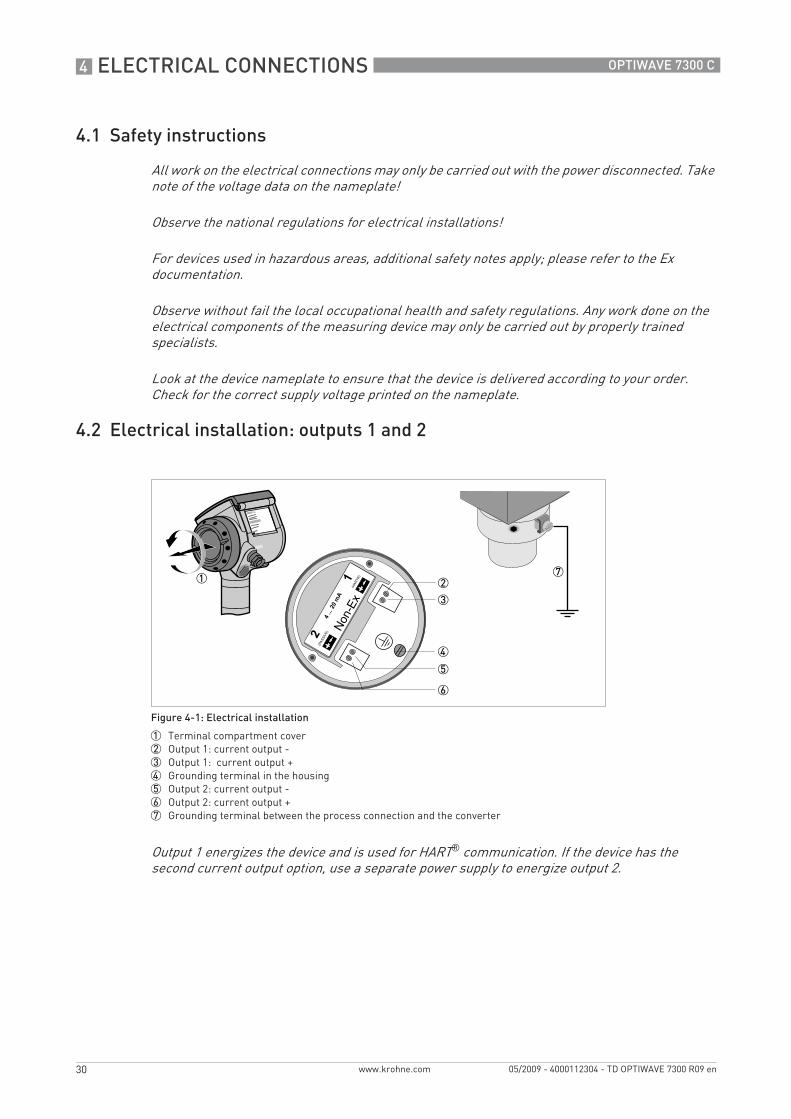
4.2 Electrical installation: outputs 1 and 2
All work on the electrical connections may only be carried out with the power disconnected. Take note of the voltage data on the nameplate!
Observe the national regulations for electrical installations!
For devices used in hazardous areas, additional safety notes apply; please refer to the Ex documentation.
Observe without fail the local occupational health and safety regulations. Any work done on the electrical components of the measuring device may only be carried out by properly trained specialists.
Look at the device nameplate to ensure that the device is delivered according to your order. Check for the correct supply voltage printed on the nameplate.
Figure 4-1: Electrical installation
1 Terminal compartment cover2 Output 1: current output -3 Output 1: current output +4 Grounding terminal in the housing5 Output 2: current output -6 Output 2: current output +7 Grounding terminal between the process connection and the converter
Output 1 energizes the device and is used for HART® communication. If the device has the second current output option, use a separate power supply to energize output 2.
TD_OPTIWAVE7300_en_090529_4000112304_R09_web.book Page 30 Thursday, June 4, 2009 8:44 AM

ELECTRICAL CONNECTIONS 4
31
OPTIWAVE 7300 C
www.krohne.com05/2009 - 4000112304 - TD OPTIWAVE 7300 R09 en
4.2.1 Non-Ex
4.2.2 Ex i
4.2.3 Ex d
Figure 4-2: Electrical connections for non-Ex devices
1 Power supply
2 Resistor for HART® communication3 Output 1: 14...30 VDC for an output of 22 mA at the terminal4 Output 2: 10...30 VDC for an output of 22 mA at the terminal
For electrical data for Ex i applications, refer to the Ex supplements. You can find this documentation on the CD-ROM delivered with the device or it can be downloaded free of charge from the website (Downloadcenter).
For electrical data for Ex d applications, refer to the Ex supplements. You can find this documentation on the CD-ROM delivered with the device or it can be downloaded free of charge from the website (Downloadcenter).
TD_OPTIWAVE7300_en_090529_4000112304_R09_web.book Page 31 Thursday, June 4, 2009 8:44 AM

4 ELECTRICAL CONNECTIONS
32
OPTIWAVE 7300 C
www.krohne.com 05/2009 - 4000112304 - TD OPTIWAVE 7300 R09 en
4.3 Protection category
• Make sure that the gaskets are not damaged.• Make sure that the electrical cables are not damaged.• Make sure that the electrical cables agree with the national electrical code.• The cables are in a loop in front of the device 1 so water does not go into the housing.• Tighten the cable feedthroughs 2.• Close unused cable feedthroughs with dummy plugs 3.
The device fulfills all requirements per protection class IP 66/67 (equivalent to NEMA 6-6X).
Make sure the cable gland is watertight.
Figure 4-3: How to make the installation agree with protection category IP 67
TD_OPTIWAVE7300_en_090529_4000112304_R09_web.book Page 32 Thursday, June 4, 2009 8:44 AM

ELECTRICAL CONNECTIONS 4
33
OPTIWAVE 7300 C
www.krohne.com05/2009 - 4000112304 - TD OPTIWAVE 7300 R09 en
4.4 Networks
4.4.1 General information
The device uses the HART® communication protocol. This protocol agrees with the HART® Communication Foundation standard. The device can be connected point-to-point. It can also operate in a multi-drop network of up to 15 devices.
Output 1 is factory-set to communicate point-to-point. To change the communication mode from point-to-pointpoint-to-pointpoint-to-pointpoint-to-point to multi-dropmulti-dropmulti-dropmulti-drop, refer to "Network configuration" in the handbook.
4.4.2 Point-to-point connection
Figure 4-4: Point-to-point connection (non-Ex)
1 Address of the device (0 for point-to-point connection)
2 4...20 mA + HART®
3 Resistor for HART® communication4 Power supply
5 HART® converter
6 HART® communication software
TD_OPTIWAVE7300_en_090529_4000112304_R09_web.book Page 33 Thursday, June 4, 2009 8:44 AM

4 ELECTRICAL CONNECTIONS
34
OPTIWAVE 7300 C
www.krohne.com 05/2009 - 4000112304 - TD OPTIWAVE 7300 R09 en
4.4.3 Multi-drop networks
Figure 4-5: Multi-drop network (non-Ex)
1 Address of the device (n+1 for multidrop networks)2 Address of the device (1 for multidrop networks)
3 4 mA + HART®
4 Resistor for HART® communication5 Power supply
6 HART® converter
7 HART® communication software
TD_OPTIWAVE7300_en_090529_4000112304_R09_web.book Page 34 Thursday, June 4, 2009 8:44 AM

ORDER FORM 5
35
OPTIWAVE 7300 C
www.krohne.com05/2009 - 4000112304 - TD OPTIWAVE 7300 R09 en
Order form
You can help us to assist you as quickly as possible by giving us a few items of information.
Then just fax them to us. Your personal consultant will contact you within 24 hours.
5.1 Device data
5.2 Rating data
Connection type Flange Threaded Specify size:
Connection material 316 L Hastelloy® C-22
Feedthrough/Sealing Standard/ FKM/FPM(-40...+200°C)
Standard/ Kalrez® 6375(-20...+200°C)
Standard/ EPDM (-40...+150°C)
Metaglas®/ FKM/FPM(-30...+200°C)
Metaglas®/ Kalrez® 6375 (-20...+200°C)
Metaglas®/ EPDM (-30...+150°C)
Outputs 1 output 4...20 mA/HART®
2 outputs 4...20 mA/HART® + 4...20 mA
Display Without With Specify language:
Approvals No Ex ATEX II G 1, 1/2, 2 Ex ia IIC T6...T3
ATEX II G 1/2, 2 Ex d[ia] IIC T6...T3
WHG ATEX II D 1, 1/2, 2 Ex iaD 20 or Ex iaD 20/21 or Ex iaD 21 IP6X T65°C...T90°C
ATEX II D 1/2, 2 Ex tD[iaD] A21/20 or Ex tD[iaD] A21 IP6X T65°C...T90°C
FM/CSA IS Class 1 Div. 1 (Dual Seal)
FM/CSA XP Class 1 Div. 1 (Dual Seal) 1
IECEx Zone 0/20 Ex ia IIC T3...T6
ATEX II G 3 Ex nA II T6...T3
1 Div. 1 not for CSA
Product name:
Operating pressure:
Rated pressure:
Process connection temperature:
Ambient temperature:
Operating density:
Viscosity:
Measurand (level, volume,...):
Tank height:
Comments (indoors, exposed to weather, ...):
TD_OPTIWAVE7300_en_090529_4000112304_R09_web.book Page 35 Thursday, June 4, 2009 8:44 AM
5 ORDER FORM
36
OPTIWAVE 7300 C
www.krohne.com 05/2009 - 4000112304 - TD OPTIWAVE 7300 R09 en
5.3 Contact data
Company:
Contact person:
Telephone number:
Fax number:
E-mail:
TD_OPTIWAVE7300_en_090529_4000112304_R09_web.book Page 36 Thursday, June 4, 2009 8:44 AM

NOTES 6
37
OPTIWAVE 7300 C
www.krohne.com05/2009 - 4000112304 - TD OPTIWAVE 7300 R09 en
Notes
TD_OPTIWAVE7300_en_090529_4000112304_R09_web.book Page 37 Thursday, June 4, 2009 8:44 AM

6 NOTES
38
OPTIWAVE 7300 C
www.krohne.com 05/2009 - 4000112304 - TD OPTIWAVE 7300 R09 en
TD_OPTIWAVE7300_en_090529_4000112304_R09_web.book Page 38 Thursday, June 4, 2009 8:44 AM

NOTES 6
39
OPTIWAVE 7300 C
www.krohne.com05/2009 - 4000112304 - TD OPTIWAVE 7300 R09 en
TD_OPTIWAVE7300_en_090529_4000112304_R09_web.book Page 39 Thursday, June 4, 2009 8:44 AM

KROHNE product overview
• Electromagnetic flowmeters
• Variable area flowmeters
• Ultrasonic flowmeters
• Mass flowmeters
• Vortex flowmeters
• Flow controllers
• Level meters
• Temperature meters
• Pressure meters
• Analysis products
• Measuring systems for the oil and gas industry
• Measuring systems for sea-going tankers
Head Office KROHNE Messtechnik GmbH & Co. KG Ludwig-Krohne-Str. 5D-47058 Duisburg (Germany)Tel.:+49 (0)203 301 0Fax:+49 (0)203 301 10389 [email protected]
© K
RO
HN
E 05
/200
9 -
4000
1123
04 -
TD
OP
TIW
AVE
730
0 R
09 e
n -
Subj
ect t
o ch
ange
with
out n
otic
e.
The current list of all KROHNE contacts and addresses can be found at:www.krohne.com
KK
K
TD_OPTIWAVE7300_en_090529_4000112304_R09_web.book Page 40 Thursday, June 4, 2009 8:44 AM