Embed Size (px)
Citation preview
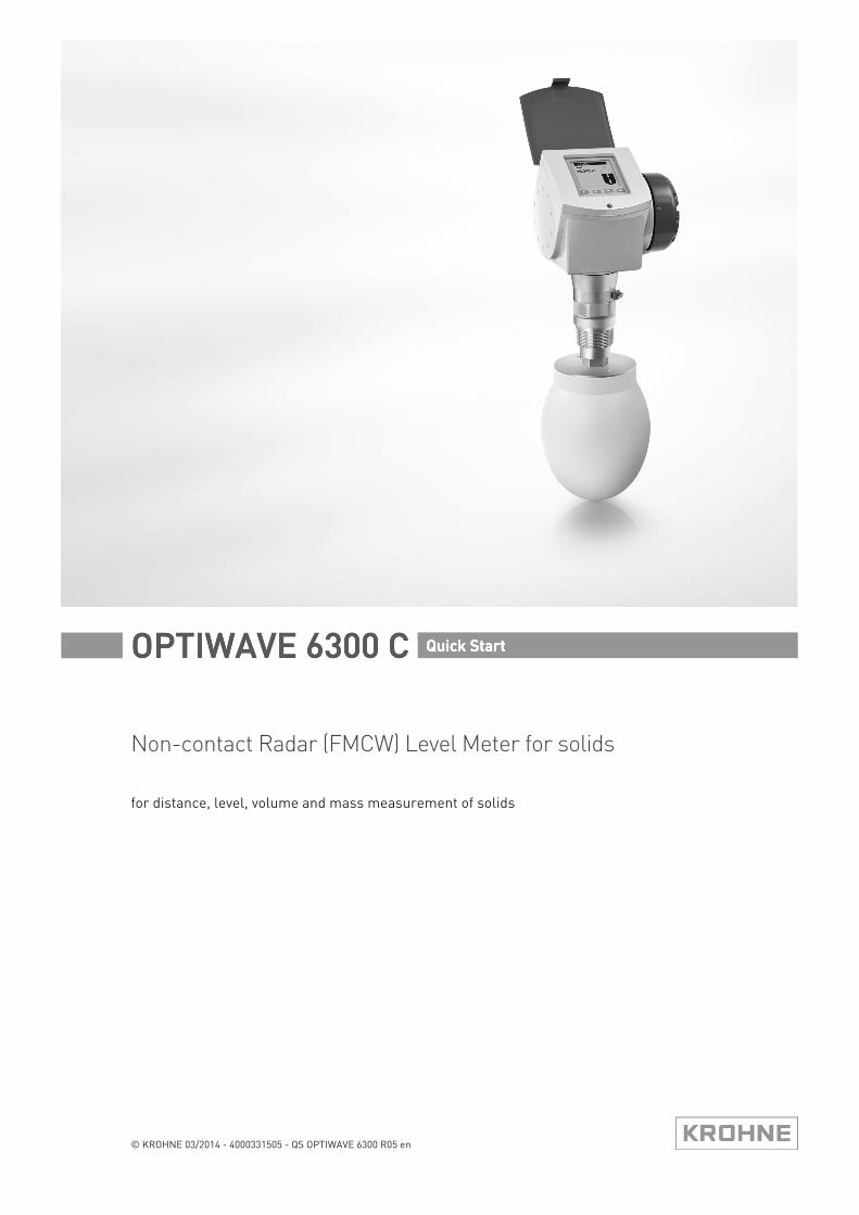
Non-contact Radar (FMCW) Level Meter for solids
for distance, level, volume and mass measurement of solids
OPTIWAVE 6300 COPTIWAVE 6300 COPTIWAVE 6300 COPTIWAVE 6300 C Quick Start Quick Start Quick Start Quick Start
© KROHNE 03/2014 - 4000331505 - QS OPTIWAVE 6300 R05 en
CONTENTS
2 www.krohne.com 03/2014 - 4000331505 - QS OPTIWAVE 6300 R05 en
OPTIWAVE 6300 C
1 Safety instructions 3
2 Installation 4
2.1 Intended use ..................................................................................................................... 42.2 Scope of delivery............................................................................................................... 52.3 Visual Check ..................................................................................................................... 62.4 Storage ............................................................................................................................. 72.5 Transport .......................................................................................................................... 82.6 Pre-installation requirements ......................................................................................... 82.7 How to prepare the silo before you install the device ..................................................... 9
2.7.1 Pressure and temperature ranges......................................................................................... 92.7.2 Recommended mounting position........................................................................................ 10
2.8 Installation recommendations for solids....................................................................... 112.9 How to install the device on the silo .............................................................................. 12
2.9.1 How to install a device with a flange connection ................................................................. 122.9.2 How to install a device with a threaded connection ............................................................. 132.9.3 How to attach antenna extensions ....................................................................................... 142.9.4 How to turn or remove the signal converter ........................................................................ 152.9.5 How to attach the weather protection to the device............................................................. 162.9.6 How to open the weather protection .................................................................................... 17
3 Electrical connections 18
3.1 Safety instructions.......................................................................................................... 183.2 Electrical installation: outputs 1 and 2 .......................................................................... 18
3.2.1 Non-Ex devices ..................................................................................................................... 193.2.2 Devices for hazardous locations........................................................................................... 19
3.3 Protection category ........................................................................................................ 20
4 Technical data 21
4.1 Technical data................................................................................................................. 21
5 Notes 26
SAFETY INSTRUCTIONS 1
3
OPTIWAVE 6300 C
www.krohne.com03/2014 - 4000331505 - QS OPTIWAVE 6300 R05 en
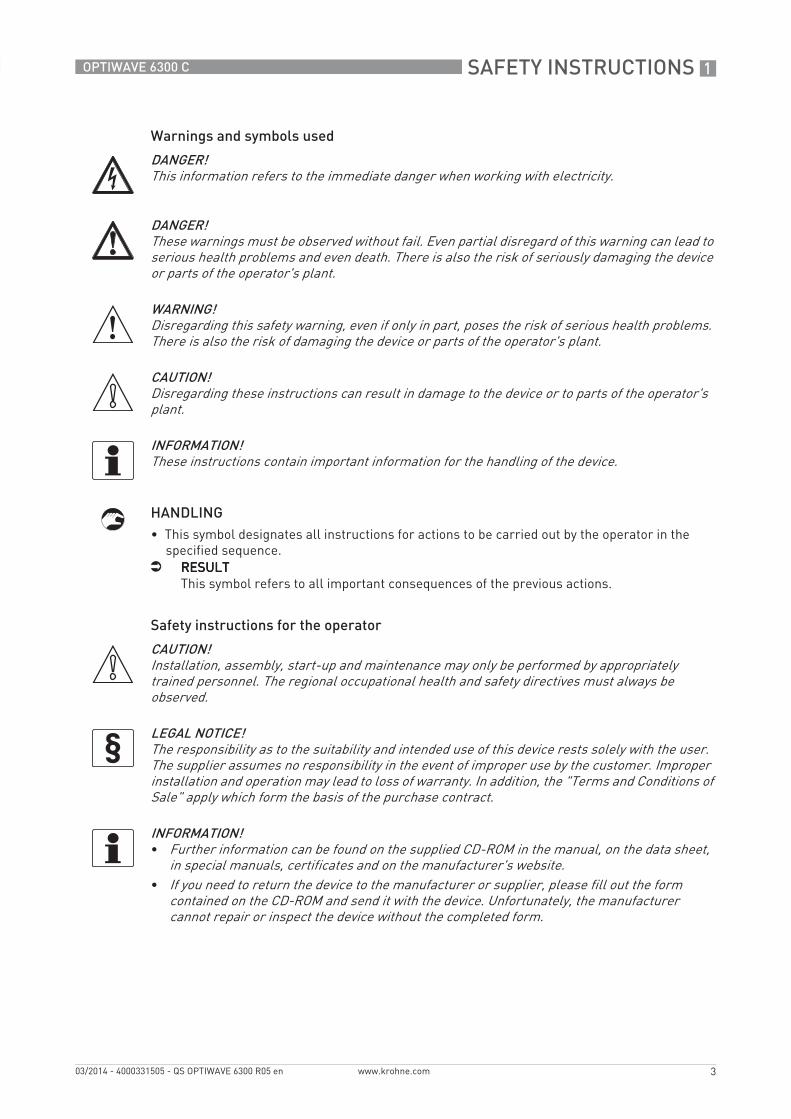
Warnings and symbols used
HANDLING• This symbol designates all instructions for actions to be carried out by the operator in the
specified sequence.i RESULTRESULTRESULTRESULT
This symbol refers to all important consequences of the previous actions.
Safety instructions for the operator
DANGER!This information refers to the immediate danger when working with electricity.
DANGER!These warnings must be observed without fail. Even partial disregard of this warning can lead to serious health problems and even death. There is also the risk of seriously damaging the device or parts of the operator's plant.
WARNING!Disregarding this safety warning, even if only in part, poses the risk of serious health problems. There is also the risk of damaging the device or parts of the operator's plant.
CAUTION!Disregarding these instructions can result in damage to the device or to parts of the operator's plant.
INFORMATION!These instructions contain important information for the handling of the device.
CAUTION!Installation, assembly, start-up and maintenance may only be performed by appropriately trained personnel. The regional occupational health and safety directives must always be observed.
LEGAL NOTICE!The responsibility as to the suitability and intended use of this device rests solely with the user. The supplier assumes no responsibility in the event of improper use by the customer. Improper installation and operation may lead to loss of warranty. In addition, the "Terms and Conditions of Sale" apply which form the basis of the purchase contract.
INFORMATION!• Further information can be found on the supplied CD-ROM in the manual, on the data sheet,
in special manuals, certificates and on the manufacturer's website.• If you need to return the device to the manufacturer or supplier, please fill out the form
contained on the CD-ROM and send it with the device. Unfortunately, the manufacturer cannot repair or inspect the device without the completed form.
2 INSTALLATION
4
OPTIWAVE 6300 C
www.krohne.com 03/2014 - 4000331505 - QS OPTIWAVE 6300 R05 en
2.1 Intended use
This radar level transmitter measures distance, level, mass, volume and reflectivity of granulates and powders.
It can be installed on silos, hoppers and bunkers.
INSTALLATION 2
5
OPTIWAVE 6300 C
www.krohne.com03/2014 - 4000331505 - QS OPTIWAVE 6300 R05 en
2.2 Scope of delivery
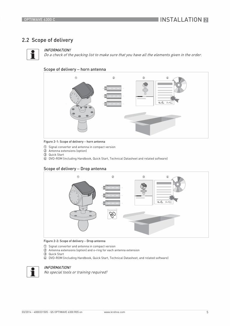
INFORMATION!Do a check of the packing list to make sure that you have all the elements given in the order.
Scope of delivery – horn antenna
Figure 2-1: Scope of delivery – horn antenna
1 Signal converter and antenna in compact version2 Antenna extensions (option)3 Quick Start4 DVD-ROM (including Handbook, Quick Start, Technical Datasheet and related software)
Scope of delivery – Drop antenna
Figure 2-2: Scope of delivery – Drop antenna
1 Signal converter and antenna in compact version2 Antenna extensions (option) and o-ring for each antenna extension3 Quick Start4 DVD-ROM (including Handbook, Quick Start, Technical Datasheet, and related software)
INFORMATION!No special tools or training required!
2 INSTALLATION
6
OPTIWAVE 6300 C
www.krohne.com 03/2014 - 4000331505 - QS OPTIWAVE 6300 R05 en
2.3 Visual Check
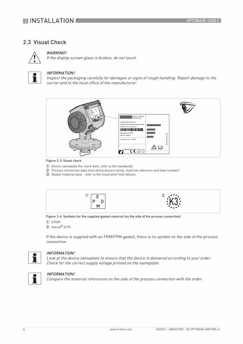
If the device is supplied with an FKM/FPM gasket, there is no symbol on the side of the process connection.
WARNING!If the display screen glass is broken, do not touch.
INFORMATION!Inspect the packaging carefully for damages or signs of rough handling. Report damage to the carrier and to the local office of the manufacturer.
Figure 2-3: Visual check
1 Device nameplate (for more data, refer to the handbook)2 Process connection data (size and pressure rating, material reference and heat number)3 Gasket material data - refer to the illustration that follows
Figure 2-4: Symbols for the supplied gasket material (on the side of the process connection)
1 EPDM
2 Kalrez® 6375
INFORMATION!Look at the device nameplate to ensure that the device is delivered according to your order. Check for the correct supply voltage printed on the nameplate.
INFORMATION!Compare the material references on the side of the process connection with the order.
INSTALLATION 2
7
OPTIWAVE 6300 C
www.krohne.com03/2014 - 4000331505 - QS OPTIWAVE 6300 R05 en
2.4 Storage
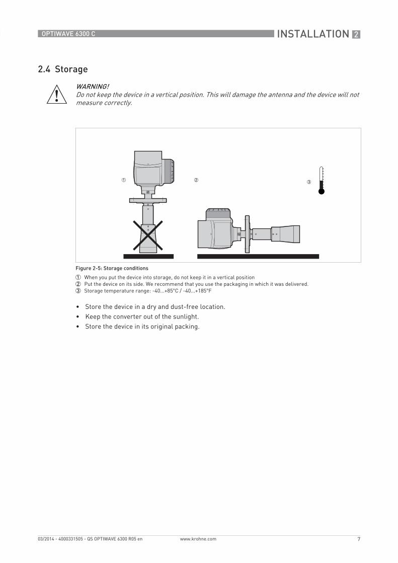
• Store the device in a dry and dust-free location.• Keep the converter out of the sunlight.• Store the device in its original packing.
WARNING!Do not keep the device in a vertical position. This will damage the antenna and the device will not measure correctly.
Figure 2-5: Storage conditions
1 When you put the device into storage, do not keep it in a vertical position2 Put the device on its side. We recommend that you use the packaging in which it was delivered.3 Storage temperature range: -40...+85°C / -40...+185°F
2 INSTALLATION
8
OPTIWAVE 6300 C
www.krohne.com 03/2014 - 4000331505 - QS OPTIWAVE 6300 R05 en
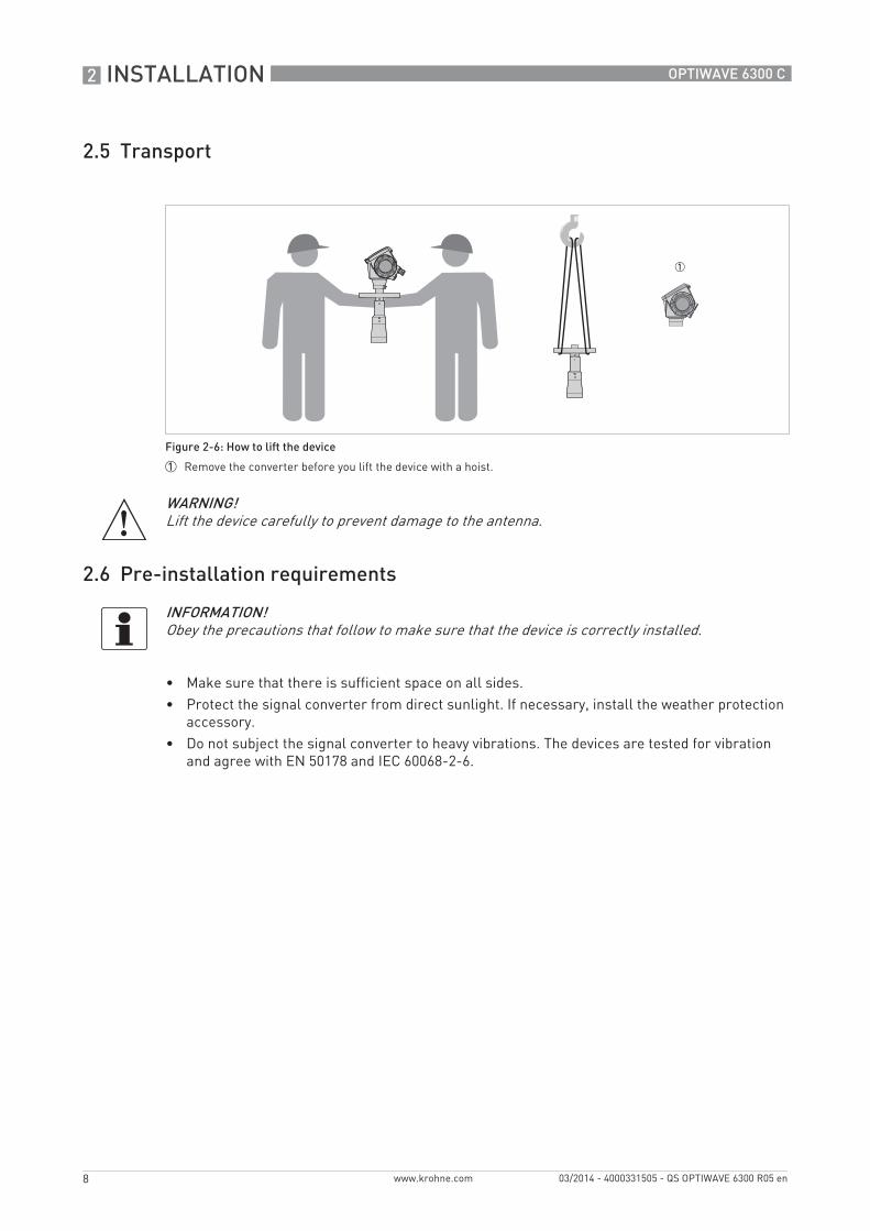
2.5 Transport
2.6 Pre-installation requirements
• Make sure that there is sufficient space on all sides.• Protect the signal converter from direct sunlight. If necessary, install the weather protection
accessory.• Do not subject the signal converter to heavy vibrations. The devices are tested for vibration
and agree with EN 50178 and IEC 60068-2-6.
Figure 2-6: How to lift the device
1 Remove the converter before you lift the device with a hoist.
WARNING!Lift the device carefully to prevent damage to the antenna.
INFORMATION!Obey the precautions that follow to make sure that the device is correctly installed.
INSTALLATION 2
9
OPTIWAVE 6300 C
www.krohne.com03/2014 - 4000331505 - QS OPTIWAVE 6300 R05 en
2.7 How to prepare the silo before you install the device
2.7.1 Pressure and temperature ranges
CAUTION!To avoid measuring errors and device malfunction, obey these precautions.
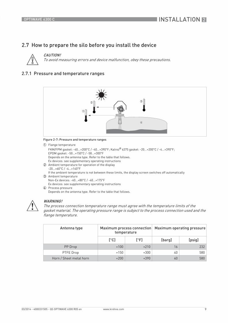
Figure 2-7: Pressure and temperature ranges
1 Flange temperature
FKM/FPM gasket: -40...+200°C / -40...+390°F; Kalrez® 6375 gasket: -20...+200°C / -4...+390°F;EPDM gasket: -50...+150°C / -58...+300°FDepends on the antenna type. Refer to the table that follows.Ex devices: see supplementary operating instructions
2 Ambient temperature for operation of the display-20...+60°C / -4...+140°FIf the ambient temperature is not between these limits, the display screen switches off automatically
3 Ambient temperatureNon-Ex devices: -40...+80°C / -40...+175°FEx devices: see supplementary operating instructions
4 Process pressureDepends on the antenna type. Refer to the table that follows.
WARNING!The process connection temperature range must agree with the temperature limits of the gasket material. The operating pressure range is subject to the process connection used and the flange temperature.
Antenna type Maximum process connection temperature
Maximum operating pressure
[°C] [°F] [barg] [psig]
PP Drop +100 +210 16 232
PTFE Drop +150 +300 40 580
Horn / Sheet metal horn +200 +390 40 580
2 INSTALLATION
10
OPTIWAVE 6300 C
www.krohne.com 03/2014 - 4000331505 - QS OPTIWAVE 6300 R05 en
2.7.2 Recommended mounting position
CAUTION!Follow these recommendations to make sure that the device measures correctly.
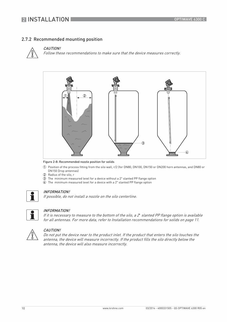
Figure 2-8: Recommended nozzle position for solids
1 Position of the process fitting from the silo wall, r/2 (for DN80, DN100, DN150 or DN200 horn antennas, and DN80 or DN150 Drop antennas)
2 Radius of the silo, r3 The minimum measured level for a device without a 2° slanted PP flange option4 The minimum measured level for a device with a 2° slanted PP flange option
INFORMATION!If possible, do not install a nozzle on the silo centerline.
INFORMATION!If it is necessary to measure to the bottom of the silo, a 2° slanted PP flange option is available for all antennas. For more data, refer to Installation recommendations for solids on page 11.
CAUTION!Do not put the device near to the product inlet. If the product that enters the silo touches the antenna, the device will measure incorrectly. If the product fills the silo directly below the antenna, the device will also measure incorrectly.
INSTALLATION 2
11
OPTIWAVE 6300 C
www.krohne.com03/2014 - 4000331505 - QS OPTIWAVE 6300 R05 en
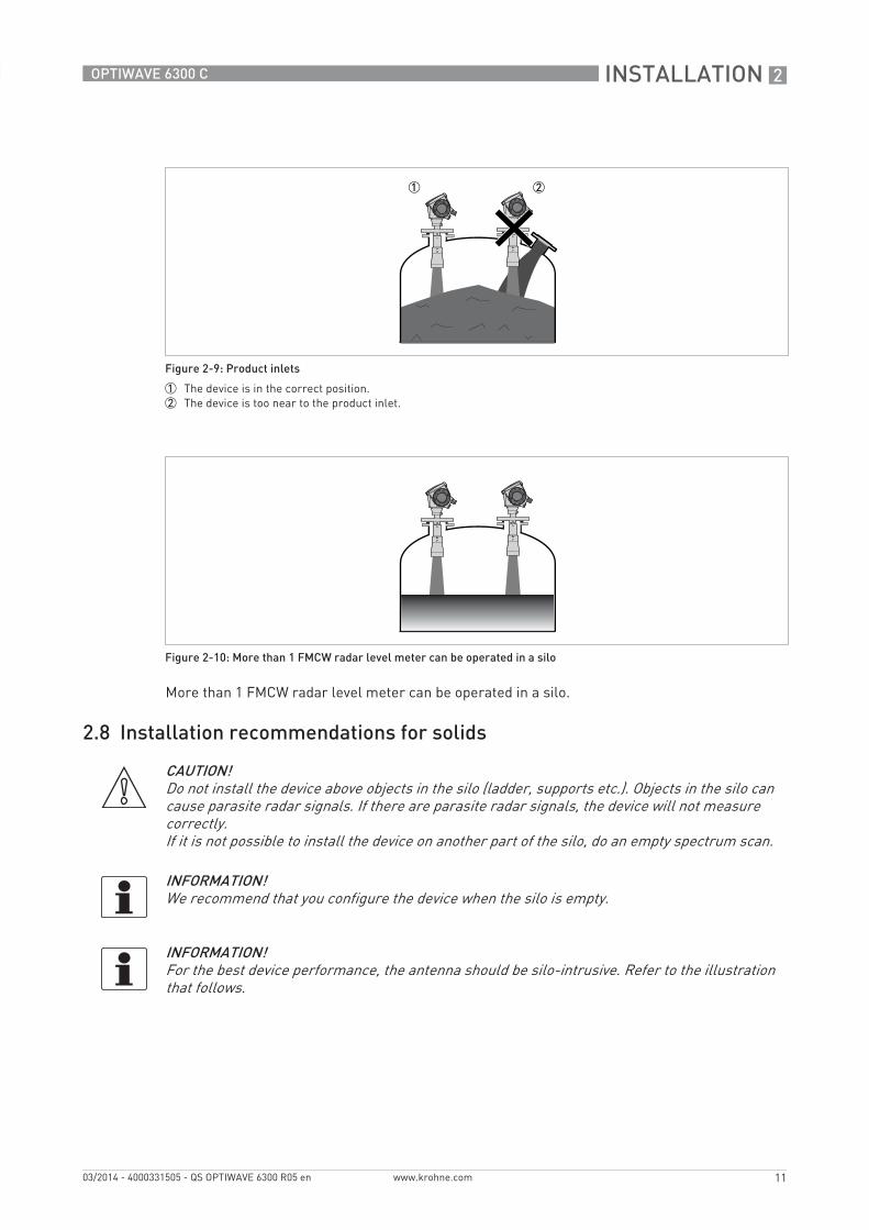
More than 1 FMCW radar level meter can be operated in a silo.
2.8 Installation recommendations for solids
Figure 2-9: Product inlets
1 The device is in the correct position.2 The device is too near to the product inlet.
Figure 2-10: More than 1 FMCW radar level meter can be operated in a silo
CAUTION!Do not install the device above objects in the silo (ladder, supports etc.). Objects in the silo can cause parasite radar signals. If there are parasite radar signals, the device will not measure correctly.If it is not possible to install the device on another part of the silo, do an empty spectrum scan.
INFORMATION!We recommend that you configure the device when the silo is empty.
INFORMATION!For the best device performance, the antenna should be silo-intrusive. Refer to the illustration that follows.
2 INSTALLATION
12
OPTIWAVE 6300 C
www.krohne.com 03/2014 - 4000331505 - QS OPTIWAVE 6300 R05 en
2.9 How to install the device on the silo
2.9.1 How to install a device with a flange connection
Equipment needed:• Device• Gasket (not supplied)• Nuts and bolts (not supplied)• Wrench (not supplied)
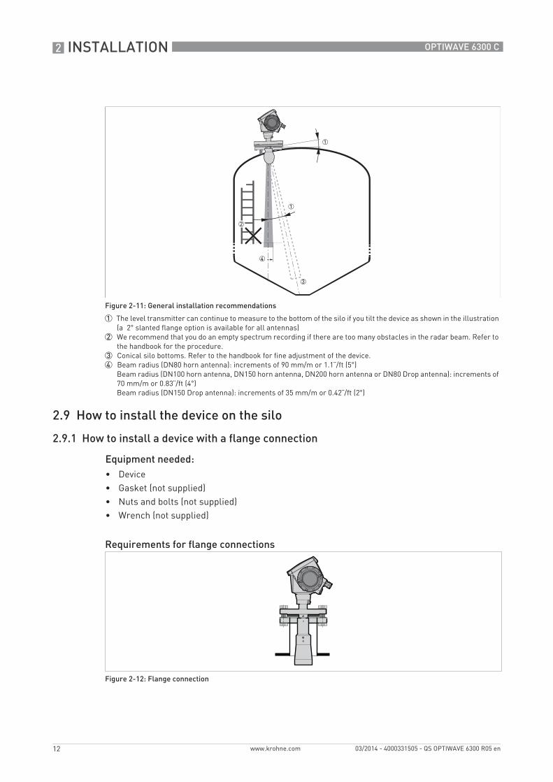
Figure 2-11: General installation recommendations
1 The level transmitter can continue to measure to the bottom of the silo if you tilt the device as shown in the illustration (a 2° slanted flange option is available for all antennas)
2 We recommend that you do an empty spectrum recording if there are too many obstacles in the radar beam. Refer to the handbook for the procedure.
3 Conical silo bottoms. Refer to the handbook for fine adjustment of the device.4 Beam radius (DN80 horn antenna): increments of 90 mm/m or 1.1¨/ft (5°)
Beam radius (DN100 horn antenna, DN150 horn antenna, DN200 horn antenna or DN80 Drop antenna): increments of 70 mm/m or 0.83¨/ft (4°)Beam radius (DN150 Drop antenna): increments of 35 mm/m or 0.42¨/ft (2°)
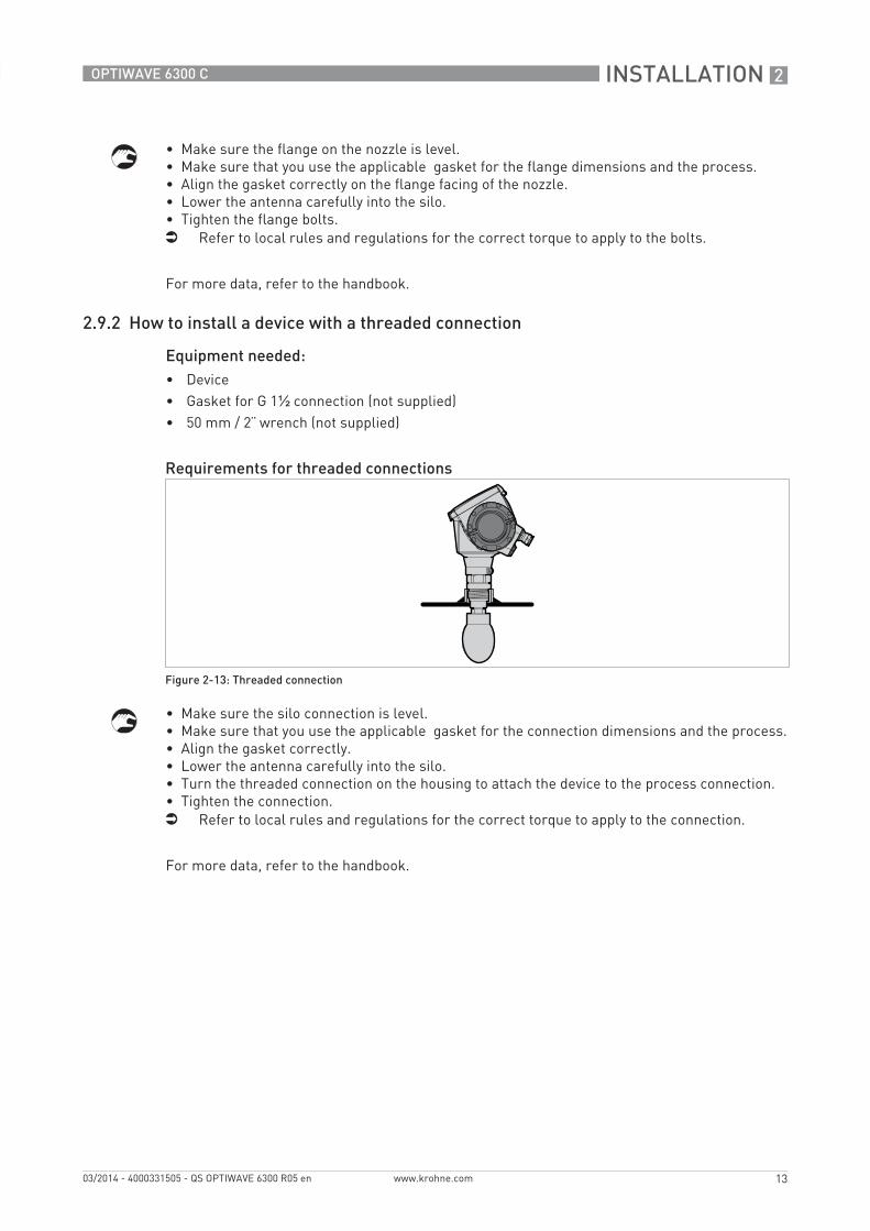
Requirements for flange connections
Figure 2-12: Flange connection
INSTALLATION 2
13
OPTIWAVE 6300 C
www.krohne.com03/2014 - 4000331505 - QS OPTIWAVE 6300 R05 en
• Make sure the flange on the nozzle is level.• Make sure that you use the applicable gasket for the flange dimensions and the process.• Align the gasket correctly on the flange facing of the nozzle.• Lower the antenna carefully into the silo.• Tighten the flange bolts.i Refer to local rules and regulations for the correct torque to apply to the bolts.
For more data, refer to the handbook.
2.9.2 How to install a device with a threaded connection
Equipment needed:• Device• Gasket for G 1½ connection (not supplied)• 50 mm / 2¨ wrench (not supplied)
• Make sure the silo connection is level.• Make sure that you use the applicable gasket for the connection dimensions and the process.• Align the gasket correctly.• Lower the antenna carefully into the silo.• Turn the threaded connection on the housing to attach the device to the process connection.• Tighten the connection.i Refer to local rules and regulations for the correct torque to apply to the connection.
For more data, refer to the handbook.
Requirements for threaded connections
Figure 2-13: Threaded connection
2 INSTALLATION
14
OPTIWAVE 6300 C
www.krohne.com 03/2014 - 4000331505 - QS OPTIWAVE 6300 R05 en
2.9.3 How to attach antenna extensions
Equipment needed:• 3 mm Allen wrench (not supplied)
For more data, refer to the handbook.
Equipment needed (not supplied):• Torque wrench 200 Nm (for the H30 head of the Drop antenna sub-assembly)• 3 mm Allen wrench
For more data, refer to the handbook.
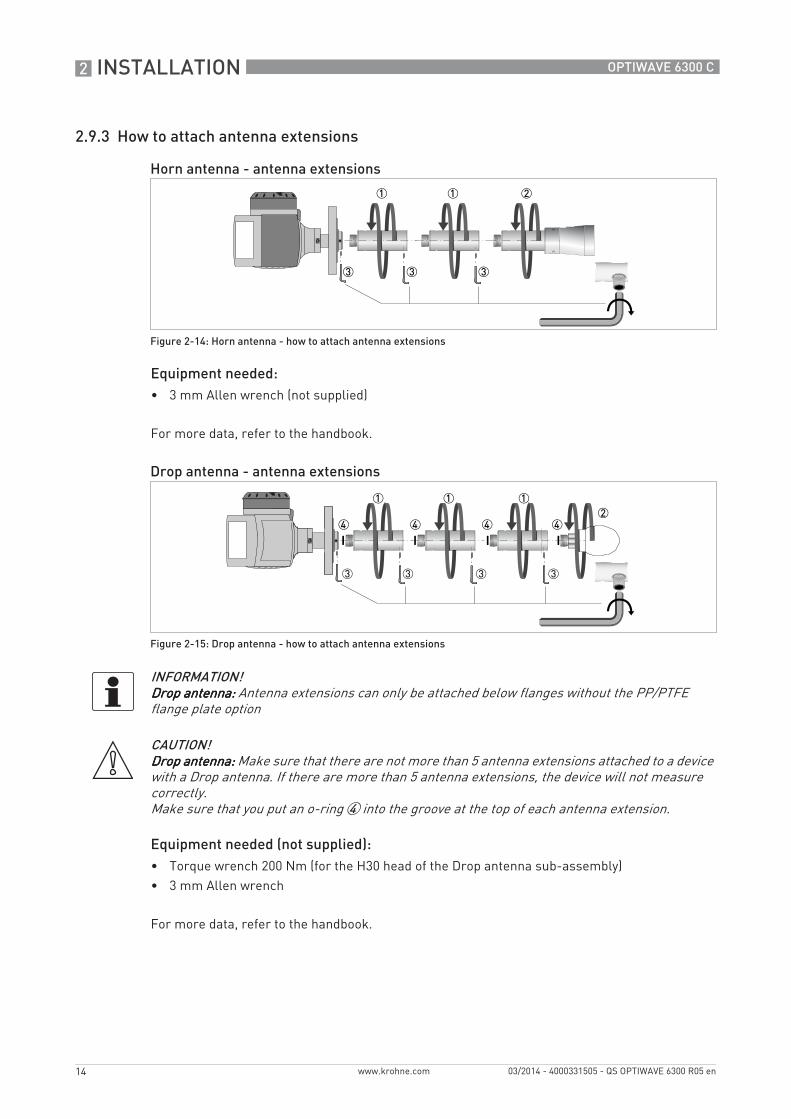
Horn antenna - antenna extensions
Figure 2-14: Horn antenna - how to attach antenna extensions
Drop antenna - antenna extensions
Figure 2-15: Drop antenna - how to attach antenna extensions
INFORMATION!Drop antenna:Drop antenna:Drop antenna:Drop antenna: Antenna extensions can only be attached below flanges without the PP/PTFE flange plate option
CAUTION!Drop antenna:Drop antenna:Drop antenna:Drop antenna: Make sure that there are not more than 5 antenna extensions attached to a device with a Drop antenna. If there are more than 5 antenna extensions, the device will not measure correctly.Make sure that you put an o-ring 4 into the groove at the top of each antenna extension.
INSTALLATION 2
15
OPTIWAVE 6300 C
www.krohne.com03/2014 - 4000331505 - QS OPTIWAVE 6300 R05 en
2.9.4 How to turn or remove the signal converter
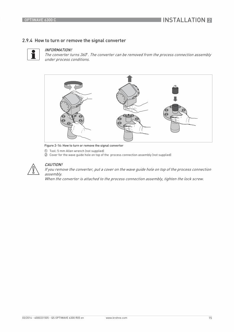
INFORMATION!The converter turns 360°. The converter can be removed from the process connection assembly under process conditions.
Figure 2-16: How to turn or remove the signal converter
1 Tool: 5 mm Allen wrench (not supplied)2 Cover for the wave guide hole on top of the process connection assembly (not supplied)
CAUTION!If you remove the converter, put a cover on the wave guide hole on top of the process connection assembly.When the converter is attached to the process connection assembly, tighten the lock screw.
2 INSTALLATION
16
OPTIWAVE 6300 C
www.krohne.com 03/2014 - 4000331505 - QS OPTIWAVE 6300 R05 en
2.9.5 How to attach the weather protection to the device
Equipment needed:• Device.• Weather protection (option).• 10 mm wrench (not supplied).
The overall dimensions of the weather protection are in "Dimensions and weight" in the handbook.
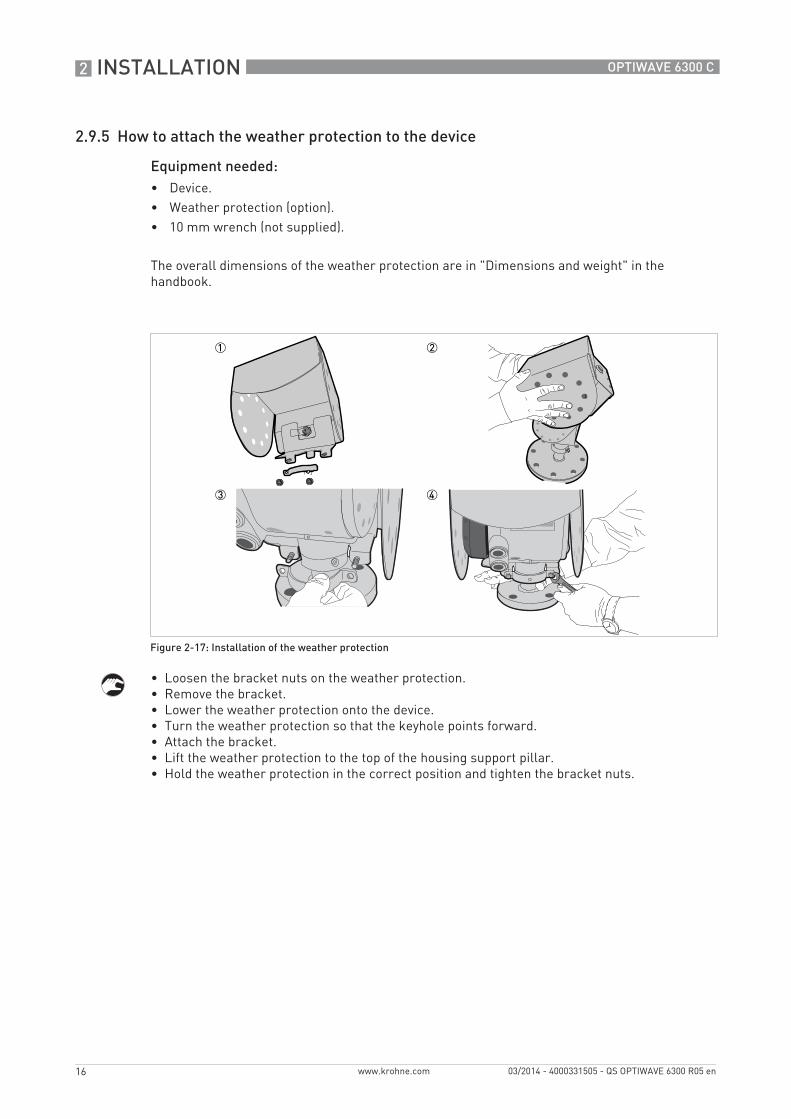
• Loosen the bracket nuts on the weather protection.• Remove the bracket.• Lower the weather protection onto the device.• Turn the weather protection so that the keyhole points forward.• Attach the bracket.• Lift the weather protection to the top of the housing support pillar.• Hold the weather protection in the correct position and tighten the bracket nuts.
Figure 2-17: Installation of the weather protection
INSTALLATION 2
17
OPTIWAVE 6300 C
www.krohne.com03/2014 - 4000331505 - QS OPTIWAVE 6300 R05 en
2.9.6 How to open the weather protection
Equipment needed:• Weather protection attached to the device.• Large slotted tip screwdriver (not supplied).
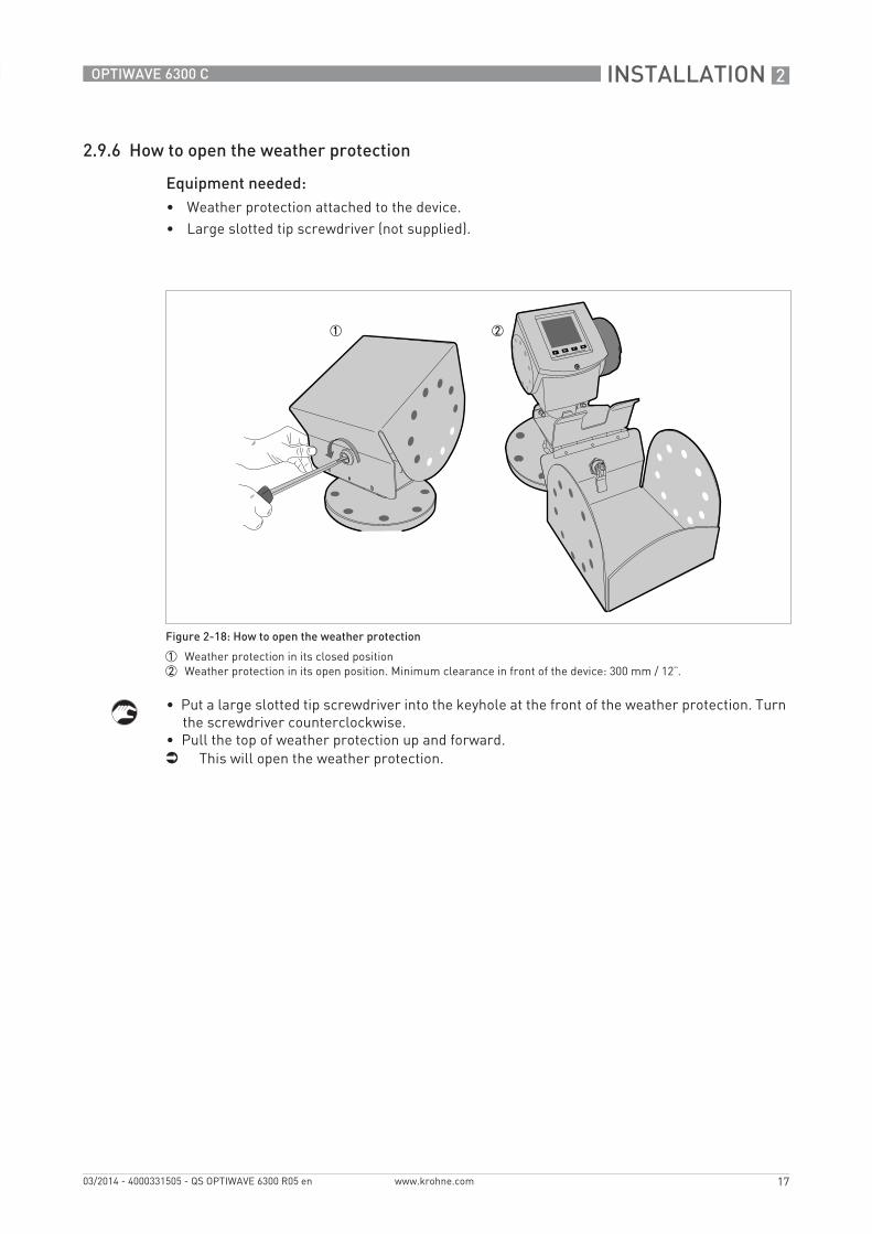
• Put a large slotted tip screwdriver into the keyhole at the front of the weather protection. Turn the screwdriver counterclockwise.
• Pull the top of weather protection up and forward.i This will open the weather protection.
Figure 2-18: How to open the weather protection
1 Weather protection in its closed position2 Weather protection in its open position. Minimum clearance in front of the device: 300 mm / 12¨.
3 ELECTRICAL CONNECTIONS
18
OPTIWAVE 6300 C
www.krohne.com 03/2014 - 4000331505 - QS OPTIWAVE 6300 R05 en
3.1 Safety instructions
3.2 Electrical installation: outputs 1 and 2
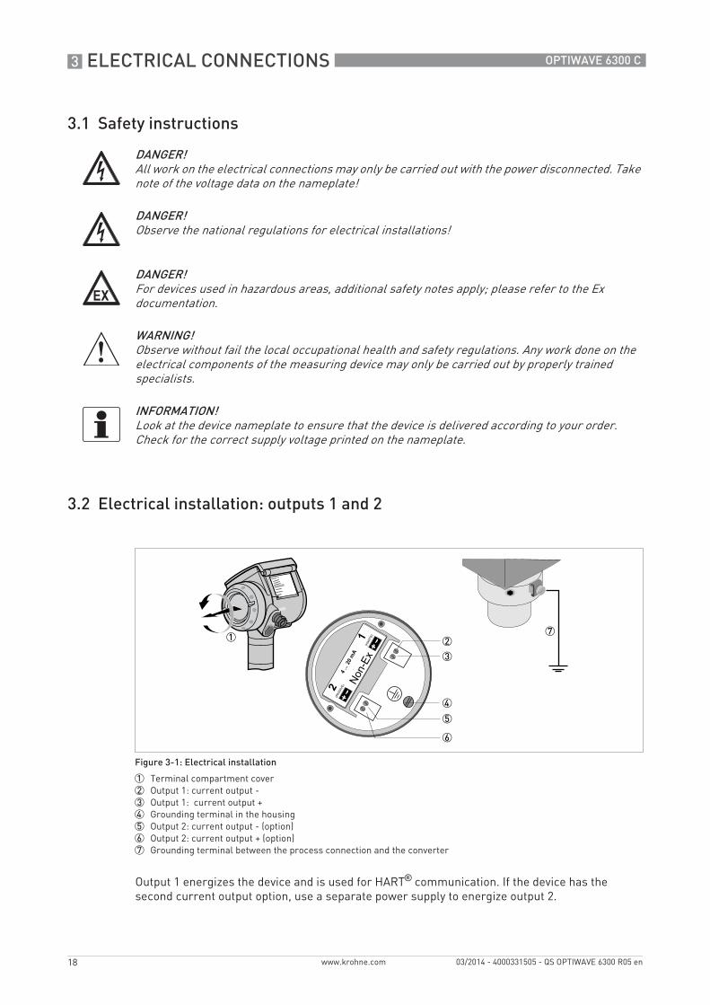
Output 1 energizes the device and is used for HART® communication. If the device has the second current output option, use a separate power supply to energize output 2.
DANGER!All work on the electrical connections may only be carried out with the power disconnected. Take note of the voltage data on the nameplate!
DANGER!Observe the national regulations for electrical installations!
DANGER!For devices used in hazardous areas, additional safety notes apply; please refer to the Ex documentation.
WARNING!Observe without fail the local occupational health and safety regulations. Any work done on the electrical components of the measuring device may only be carried out by properly trained specialists.
INFORMATION!Look at the device nameplate to ensure that the device is delivered according to your order. Check for the correct supply voltage printed on the nameplate.
Figure 3-1: Electrical installation
1 Terminal compartment cover2 Output 1: current output -3 Output 1: current output +4 Grounding terminal in the housing5 Output 2: current output - (option)6 Output 2: current output + (option)7 Grounding terminal between the process connection and the converter
ELECTRICAL CONNECTIONS 3
19
OPTIWAVE 6300 C
www.krohne.com03/2014 - 4000331505 - QS OPTIWAVE 6300 R05 en
Procedure:• Remove the housing terminal compartment cover 1.• Connect the wires to the device. Obey the national electrical codes.• Make sure that the polarity of the wires is correct.• Attach the ground to 4 or 7. Both terminals are technically equivalent.
3.2.1 Non-Ex devices
3.2.2 Devices for hazardous locations
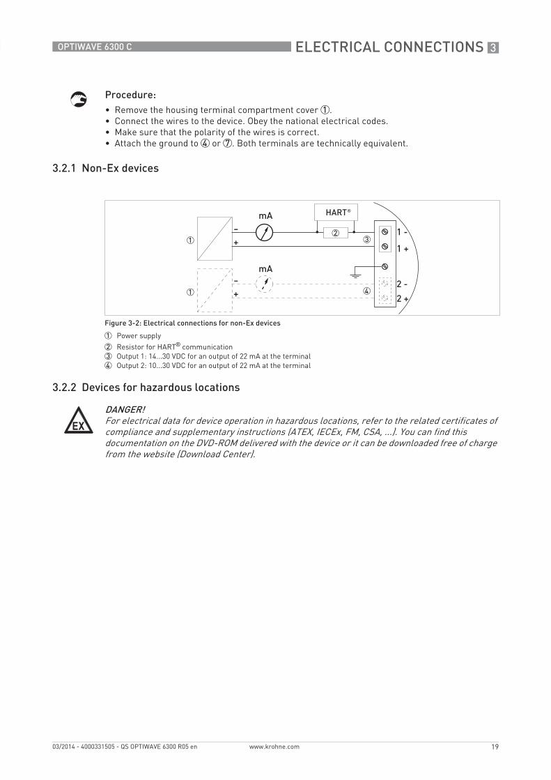
Figure 3-2: Electrical connections for non-Ex devices
1 Power supply
2 Resistor for HART® communication3 Output 1: 14...30 VDC for an output of 22 mA at the terminal4 Output 2: 10...30 VDC for an output of 22 mA at the terminal
DANGER!For electrical data for device operation in hazardous locations, refer to the related certificates of compliance and supplementary instructions (ATEX, IECEx, FM, CSA, ...). You can find this documentation on the DVD-ROM delivered with the device or it can be downloaded free of charge from the website (Download Center).
3 ELECTRICAL CONNECTIONS
20
OPTIWAVE 6300 C
www.krohne.com 03/2014 - 4000331505 - QS OPTIWAVE 6300 R05 en
3.3 Protection category
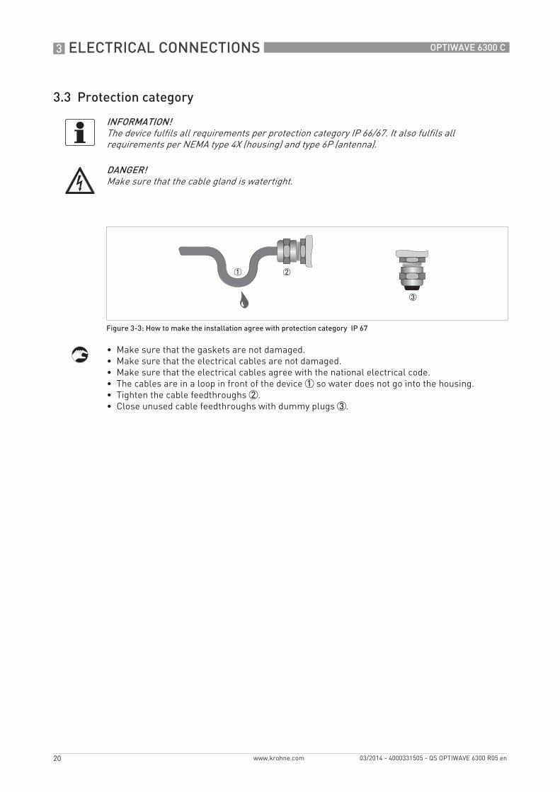
• Make sure that the gaskets are not damaged.• Make sure that the electrical cables are not damaged.• Make sure that the electrical cables agree with the national electrical code.• The cables are in a loop in front of the device 1 so water does not go into the housing.• Tighten the cable feedthroughs 2.• Close unused cable feedthroughs with dummy plugs 3.
INFORMATION!The device fulfils all requirements per protection category IP 66/67. It also fulfils all requirements per NEMA type 4X (housing) and type 6P (antenna).
DANGER!Make sure that the cable gland is watertight.
Figure 3-3: How to make the installation agree with protection category IP 67
TECHNICAL DATA 4
21
OPTIWAVE 6300 C
www.krohne.com03/2014 - 4000331505 - QS OPTIWAVE 6300 R05 en
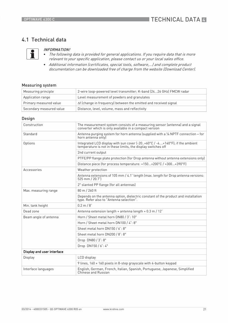
4.1 Technical data
INFORMATION!• The following data is provided for general applications. If you require data that is more
relevant to your specific application, please contact us or your local sales office.• Additional information (certificates, special tools, software,...) and complete product
documentation can be downloaded free of charge from the website (Download Center).
Measuring systemMeasuring principle 2-wire loop-powered level transmitter; K-band (24...26 GHz) FMCW radar
Application range Level measurement of powders and granulates
Primary measured value Δf (change in frequency) between the emitted and received signal
Secondary measured value Distance, level, volume, mass and reflectivity
DesignConstruction The measurement system consists of a measuring sensor (antenna) and a signal
converter which is only available in a compact version
Standard Antenna purging system for horn antenna (supplied with a ¼ NPTF connection – for horn antenna only)
Options Integrated LCD display with sun cover (-20..+60°C / -4…+140°F); if the ambient temperature is not in these limits, the display switches off
2nd current output
PTFE/PP flange plate protection (for Drop antenna without antenna extensions only)
Distance piece (for process temperature: +150...+200°C / +300...+390°F)
Accessories Weather protection
Antenna extensions of 105 mm / 4.1¨ length (max. length for Drop antenna versions: 525 mm / 20.7¨)
2° slanted PP flange (for all antennas)
Max. measuring range 80 m / 260 ft
Depends on the antenna option, dielectric constant of the product and installation type. Refer also to "Antenna selection".
Min. tank height 0.2 m / 8¨
Dead zone Antenna extension length + antenna length + 0.3 m / 12¨
Beam angle of antenna Horn / Sheet metal horn DN80 / 3¨: 10°
Horn / Sheet metal horn DN100 / 4¨: 8°
Sheet metal horn DN150 / 6¨: 8°
Sheet metal horn DN200 / 8¨: 8°
Drop DN80 / 3¨: 8°
Drop DN150 / 6¨: 4°
Display and user interfaceDisplay and user interfaceDisplay and user interfaceDisplay and user interface
Display LCD display
9 lines, 160 × 160 pixels in 8-step grayscale with 4-button keypad
Interface languages English, German, French, Italian, Spanish, Portuguese, Japanese, Simplified Chinese and Russian
4 TECHNICAL DATA
22
OPTIWAVE 6300 C
www.krohne.com 03/2014 - 4000331505 - QS OPTIWAVE 6300 R05 en
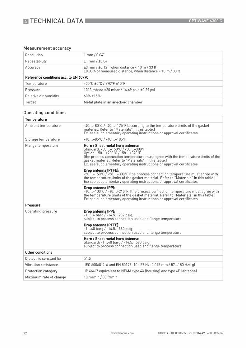
Measurement accuracyResolution 1 mm / 0.04¨
Repeatability ±1 mm / ±0.04¨
Accuracy ±3 mm / ±0.12¨, when distance < 10 m / 33 ft;±0.03% of measured distance, when distance > 10 m / 33 ft
Reference conditions acc. to EN 60770Reference conditions acc. to EN 60770Reference conditions acc. to EN 60770Reference conditions acc. to EN 60770
Temperature +20°C ±5°C / +70°F ±10°F
Pressure 1013 mbara ±20 mbar / 14.69 psia ±0.29 psi
Relative air humidity 60% ±15%
Target Metal plate in an anechoic chamber
Operating conditionsTemperatureTemperatureTemperatureTemperature
Ambient temperature -40…+80°C / -40…+175°F (according to the temperature limits of the gasket material. Refer to "Materials" in this table.)Ex: see supplementary operating instructions or approval certificates
Storage temperature -40…+85°C / -40…+185°F
Flange temperature Horn / Sheet metal horn antenna:Horn / Sheet metal horn antenna:Horn / Sheet metal horn antenna:Horn / Sheet metal horn antenna:Standard: -50…+150°C / -58…+300°FOption: -50…+200°C / -58…+390°F(the process connection temperature must agree with the temperature limits of the gasket material. Refer to "Materials" in this table.)Ex: see supplementary operating instructions or approval certificates
Drop antenna (PTFE):Drop antenna (PTFE):Drop antenna (PTFE):Drop antenna (PTFE):-50…+150°C / -58…+300°F (the process connection temperature must agree with the temperature limits of the gasket material. Refer to "Materials" in this table.)Ex: see supplementary operating instructions or approval certificates
Drop antenna (PP):Drop antenna (PP):Drop antenna (PP):Drop antenna (PP):-40…+100°C / -40…+210°F (the process connection temperature must agree with the temperature limits of the gasket material. Refer to "Materials" in this table.)Ex: see supplementary operating instructions or approval certificates
PressurePressurePressurePressure
Operating pressure Drop antenna (PP):Drop antenna (PP):Drop antenna (PP):Drop antenna (PP):-1…16 barg / -14.5…232 psig;subject to process connection used and flange temperature
Drop antenna (PTFE):Drop antenna (PTFE):Drop antenna (PTFE):Drop antenna (PTFE):-1…40 barg / -14.5…580 psig;subject to process connection used and flange temperature
Horn / Sheet metal horn antenna:Horn / Sheet metal horn antenna:Horn / Sheet metal horn antenna:Horn / Sheet metal horn antenna:Standard: -1…40 barg / -14.5…580 psig;subject to process connection used and flange temperature
Other conditionsOther conditionsOther conditionsOther conditions
Dielectric constant (εr) ≥1.5
Vibration resistance IEC 60068-2-6 and EN 50178 (10...57 Hz: 0.075 mm / 57...150 Hz:1g)
Protection category IP 66/67 equivalent to NEMA type 4X (housing) and type 6P (antenna)
Maximum rate of change 10 m/min / 33 ft/min
TECHNICAL DATA 4
23
OPTIWAVE 6300 C
www.krohne.com03/2014 - 4000331505 - QS OPTIWAVE 6300 R05 en
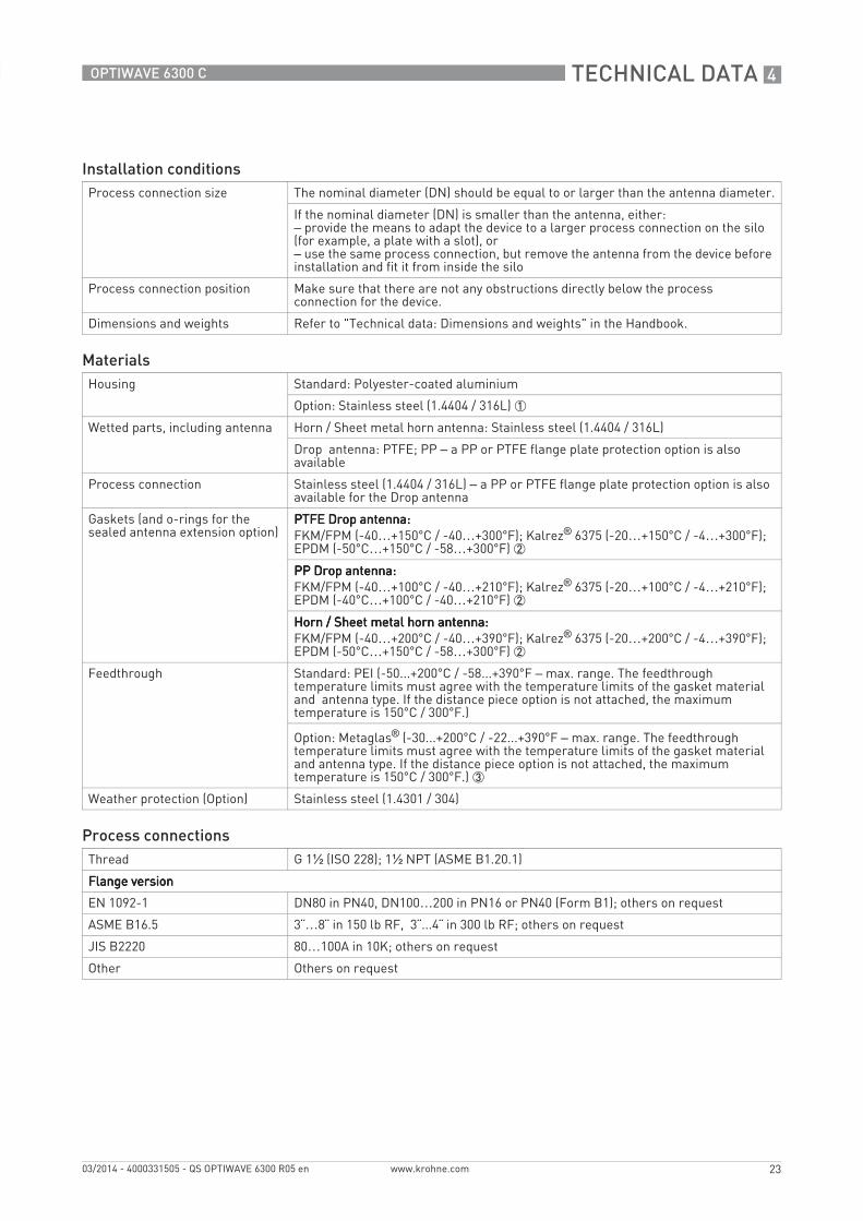
Installation conditionsProcess connection size The nominal diameter (DN) should be equal to or larger than the antenna diameter.
If the nominal diameter (DN) is smaller than the antenna, either: – provide the means to adapt the device to a larger process connection on the silo (for example, a plate with a slot), or– use the same process connection, but remove the antenna from the device before installation and fit it from inside the silo
Process connection position Make sure that there are not any obstructions directly below the process connection for the device.
Dimensions and weights Refer to "Technical data: Dimensions and weights" in the Handbook.
MaterialsHousing Standard: Polyester-coated aluminium
Option: Stainless steel (1.4404 / 316L) 1
Wetted parts, including antenna Horn / Sheet metal horn antenna: Stainless steel (1.4404 / 316L)
Drop antenna: PTFE; PP – a PP or PTFE flange plate protection option is also available
Process connection Stainless steel (1.4404 / 316L) – a PP or PTFE flange plate protection option is also available for the Drop antenna
Gaskets (and o-rings for the sealed antenna extension option)
PTFE Drop antenna:PTFE Drop antenna:PTFE Drop antenna:PTFE Drop antenna:FKM/FPM (-40…+150°C / -40…+300°F); Kalrez® 6375 (-20…+150°C / -4…+300°F);EPDM (-50°C…+150°C / -58…+300°F) 2
PP Drop antenna:PP Drop antenna:PP Drop antenna:PP Drop antenna:FKM/FPM (-40…+100°C / -40…+210°F); Kalrez® 6375 (-20…+100°C / -4…+210°F);EPDM (-40°C…+100°C / -40…+210°F) 2
Horn / Sheet metal horn antenna:Horn / Sheet metal horn antenna:Horn / Sheet metal horn antenna:Horn / Sheet metal horn antenna:FKM/FPM (-40…+200°C / -40…+390°F); Kalrez® 6375 (-20…+200°C / -4…+390°F);EPDM (-50°C…+150°C / -58…+300°F) 2
Feedthrough Standard: PEI (-50...+200°C / -58...+390°F – max. range. The feedthrough temperature limits must agree with the temperature limits of the gasket material and antenna type. If the distance piece option is not attached, the maximum temperature is 150°C / 300°F.)
Option: Metaglas® (-30...+200°C / -22...+390°F – max. range. The feedthrough temperature limits must agree with the temperature limits of the gasket material and antenna type. If the distance piece option is not attached, the maximum temperature is 150°C / 300°F.) 3
Weather protection (Option) Stainless steel (1.4301 / 304)
Process connectionsThread G 1½ (ISO 228); 1½ NPT (ASME B1.20.1)
Flange versionFlange versionFlange versionFlange version
EN 1092-1 DN80 in PN40, DN100…200 in PN16 or PN40 (Form B1); others on request
ASME B16.5 3¨…8¨ in 150 lb RF, 3¨...4¨ in 300 lb RF; others on request
JIS B2220 80…100A in 10K; others on request
Other Others on request
4 TECHNICAL DATA
24
OPTIWAVE 6300 C
www.krohne.com 03/2014 - 4000331505 - QS OPTIWAVE 6300 R05 en
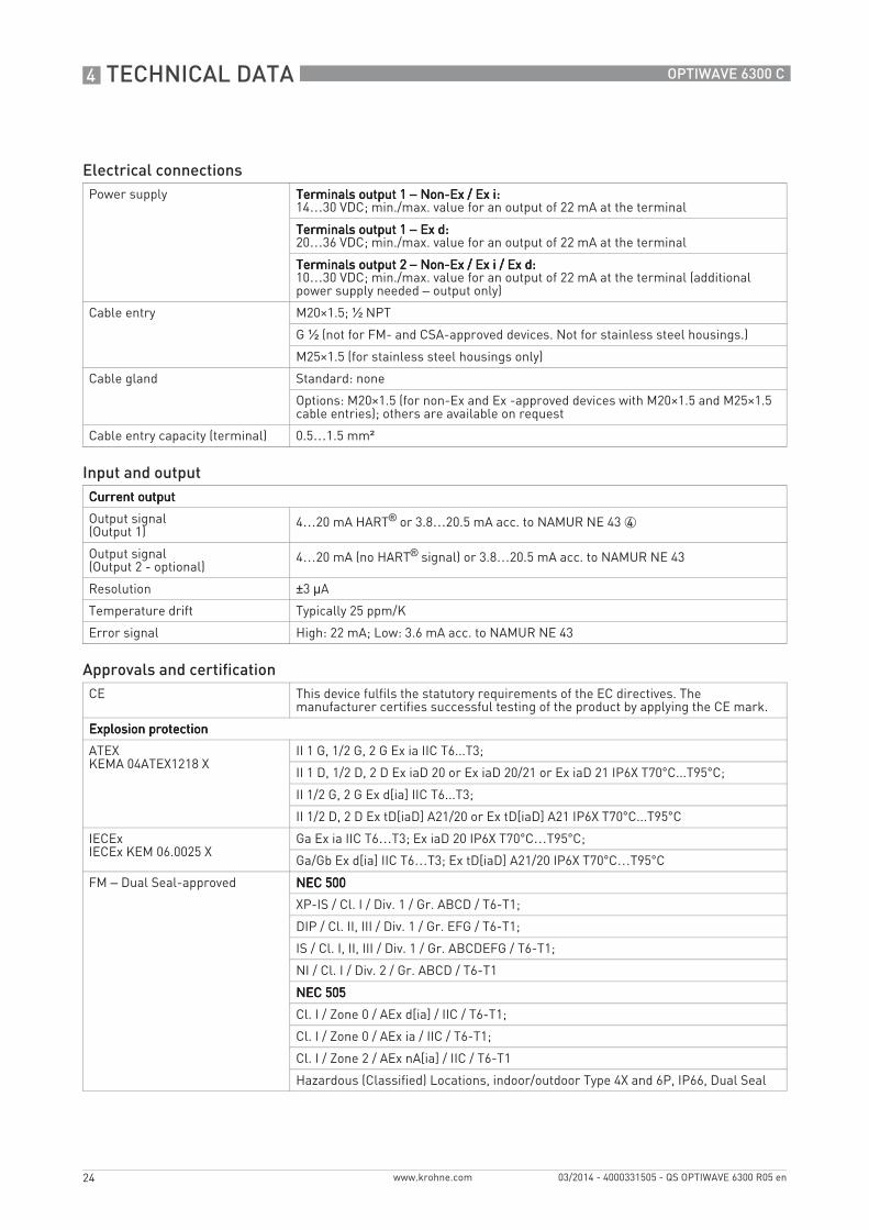
Electrical connectionsPower supply Terminals output 1 Terminals output 1 Terminals output 1 Terminals output 1 – Non-Ex / Ex i: Non-Ex / Ex i: Non-Ex / Ex i: Non-Ex / Ex i:
14…30 VDC; min./max. value for an output of 22 mA at the terminal
Terminals output 1 Terminals output 1 Terminals output 1 Terminals output 1 – Ex d: Ex d: Ex d: Ex d:20…36 VDC; min./max. value for an output of 22 mA at the terminal
Terminals output 2 Terminals output 2 Terminals output 2 Terminals output 2 – Non-Ex / Ex i / Ex d: Non-Ex / Ex i / Ex d: Non-Ex / Ex i / Ex d: Non-Ex / Ex i / Ex d:10…30 VDC; min./max. value for an output of 22 mA at the terminal (additional power supply needed – output only)
Cable entry M20×1.5; ½ NPT
G½ (not for FM- and CSA-approved devices. Not for stainless steel housings.)
M25×1.5 (for stainless steel housings only)
Cable gland Standard: none
Options: M20×1.5 (for non-Ex and Ex -approved devices with M20×1.5 and M25×1.5 cable entries); others are available on request
Cable entry capacity (terminal) 0.5…1.5 mm²
Input and outputCurrent outputCurrent outputCurrent outputCurrent output
Output signal(Output 1)
4…20 mA HART® or 3.8…20.5 mA acc. to NAMUR NE 43 4
Output signal(Output 2 - optional)
4…20 mA (no HART® signal) or 3.8…20.5 mA acc. to NAMUR NE 43
Resolution ±3 µA
Temperature drift Typically 25 ppm/K
Error signal High: 22 mA; Low: 3.6 mA acc. to NAMUR NE 43
Approvals and certificationCE This device fulfils the statutory requirements of the EC directives. The
manufacturer certifies successful testing of the product by applying the CE mark.
Explosion protectionExplosion protectionExplosion protectionExplosion protection
ATEXKEMA 04ATEX1218 X
II 1 G, 1/2 G, 2 G Ex ia IIC T6...T3;
II 1 D, 1/2 D, 2 D Ex iaD 20 or Ex iaD 20/21 or Ex iaD 21 IP6X T70°C...T95°C;
II 1/2 G, 2 G Ex d[ia] IIC T6...T3;
II 1/2 D, 2 D Ex tD[iaD] A21/20 or Ex tD[iaD] A21 IP6X T70°C...T95°C
IECExIECEx KEM 06.0025 X
Ga Ex ia IIC T6…T3; Ex iaD 20 IP6X T70°C…T95°C;
Ga/Gb Ex d[ia] IIC T6…T3; Ex tD[iaD] A21/20 IP6X T70°C…T95°C
FM – Dual Seal-approved NEC 500NEC 500NEC 500NEC 500
XP-IS / Cl. I / Div. 1 / Gr. ABCD / T6-T1;
DIP / Cl. II, III / Div. 1 / Gr. EFG / T6-T1;
IS / Cl. I, II, III / Div. 1 / Gr. ABCDEFG / T6-T1;
NI / Cl. I / Div. 2 / Gr. ABCD / T6-T1
NEC 505NEC 505NEC 505NEC 505
Cl. I / Zone 0 / AEx d[ia] / IIC / T6-T1;
Cl. I / Zone 0 / AEx ia / IIC / T6-T1;
Cl. I / Zone 2 / AEx nA[ia] / IIC / T6-T1
Hazardous (Classified) Locations, indoor/outdoor Type 4X and 6P, IP66, Dual Seal
TECHNICAL DATA 4
25
OPTIWAVE 6300 C
www.krohne.com03/2014 - 4000331505 - QS OPTIWAVE 6300 R05 en
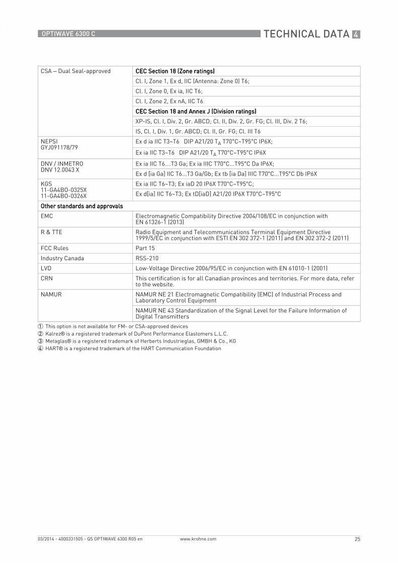
CSA – Dual Seal-approved CEC Section 18 (Zone ratings)CEC Section 18 (Zone ratings)CEC Section 18 (Zone ratings)CEC Section 18 (Zone ratings)
Cl. I, Zone 1, Ex d, IIC (Antenna: Zone 0) T6;
Cl. I, Zone 0, Ex ia, IIC T6;
Cl. I, Zone 2, Ex nA, IIC T6
CEC Section 18 and Annex J (Division ratings)CEC Section 18 and Annex J (Division ratings)CEC Section 18 and Annex J (Division ratings)CEC Section 18 and Annex J (Division ratings)
XP-IS, Cl. I, Div. 2, Gr. ABCD; Cl. II, Div. 2, Gr. FG; Cl. III, Div. 2 T6;
IS, Cl. I, Div. 1, Gr. ABCD; Cl. II, Gr. FG; Cl. III T6
NEPSIGYJ091178/79
Ex d ia IIC T3~T6 DIP A21/20 TA T70°C~T95°C IP6X;
Ex ia IIC T3~T6 DIP A21/20 TA T70°C~T95°C IP6X
DNV / INMETRODNV 12.0043 X
Ex ia IIC T6…T3 Ga; Ex ia IIIC T70°C...T95°C Da IP6X;
Ex d [ia Ga] IIC T6...T3 Ga/Gb; Ex tb [ia Da] IIIC T70°C...T95°C Db IP6X
KGS11-GA4BO-0325X11-GA4BO-0326X
Ex ia IIC T6~T3; Ex iaD 20 IP6X T70°C~T95°C;
Ex d[ia] IIC T6~T3; Ex tD[iaD] A21/20 IP6X T70°C~T95°C
Other standards and approvalsOther standards and approvalsOther standards and approvalsOther standards and approvals
EMC Electromagnetic Compatibility Directive 2004/108/EC in conjunction with EN 61326-1 (2013)
R & TTE Radio Equipment and Telecommunications Terminal Equipment Directive 1999/5/EC in conjunction with ESTI EN 302 372-1 (2011) and EN 302 372-2 (2011)
FCC Rules Part 15
Industry Canada RSS-210
LVD Low-Voltage Directive 2006/95/EC in conjunction with EN 61010-1 (2001)
CRN This certification is for all Canadian provinces and territories. For more data, refer to the website.
NAMUR NAMUR NE 21 Electromagnetic Compatibility (EMC) of Industrial Process and Laboratory Control Equipment
NAMUR NE 43 Standardization of the Signal Level for the Failure Information of Digital Transmitters
1 This option is not available for FM- or CSA-approved devices2 Kalrez® is a registered trademark of DuPont Performance Elastomers L.L.C.3 Metaglas® is a registered trademark of Herberts Industrieglas, GMBH & Co., KG4 HART® is a registered trademark of the HART Communication Foundation
5 NOTES
26
OPTIWAVE 6300 C
www.krohne.com 03/2014 - 4000331505 - QS OPTIWAVE 6300 R05 en

NOTES 5
27
OPTIWAVE 6300 C
www.krohne.com03/2014 - 4000331505 - QS OPTIWAVE 6300 R05 en
KROHNE product overview
• Electromagnetic flowmeters
• Variable area flowmeters
• Ultrasonic flowmeters
• Mass flowmeters
• Vortex flowmeters
• Flow controllers
• Level meters
• Temperature assemblies
• Pressure transmitters
• Analysis products
• Products and systems for the oil & gas industry
• Measuring systems for the marine industry
Head Office KROHNE Messtechnik GmbHLudwig-Krohne-Str. 547058 Duisburg (Germany)Tel.:+49 203 301 0Fax:+49 203 301 103 89 [email protected]
© K
RO
HN
E 03
/201
4 -
4000
3315
05 -
QS
OP
TIW
AVE
630
0 R
05 e
n -
Subj
ect t
o ch
ange
with
out n
otic
e.
The current list of all KROHNE contacts and addresses can be found at:www.krohne.com