Embed Size (px)
Citation preview

MICROWAVEPRELIMINARY DATASHEET | AUGUST 2020
© 2020 EMCORE Corporation | REV 2020.08
Information contained herein is deemed to be reliable and accurate as of the issue date. EMCORE reserves the right to change the design or specifications at any time without notice.EMCORE is a registered trademark of EMCORE Corporation in the U.S. and other countries.
Optiva OTS-2 Q/V-Band 60 GHz Unamplified Microwave Band Fiber Optic Links
[email protected] www.emcore.com+1 626-293-3400
System Design
The Optiva OTS-2 Q/V-Band 60 GHz Microwave Band transmitter and receiver are ideal to construct transparent fiber optic links in the 50 MHz to 60 GHz frequency range for antenna remoting, electronic warfare systems, broadband delay lines, signal processing systems and other high-dynamic-range applications.
Optiva microwave band transmitters and receivers are SNMP compliant. They can be housed in the same chassis and monitored by the same Network Man-agement System (NMS) as other Optiva cards to support transport of multiple signal formats and frequency bands in a single flexible platform.
50 MHz to 60 GHz Unamplified Microwave Transport System
Features / Benefits
� 50 MHz - 60 GHz - Eliminates the performance and cost penalty of block up/down conversion
� Low RIN Source Laser - Provides high dynamic range of >104 dB-Hz2/3 sub-octave
� Microprocessor-Based Transmitter Control for Laser Bias, Modulator Bias & Link Gain - Provides consistent high performance operation and allows for modulator low-bias operation and higher SFDR
� Compatible with EMCORE’s Modular Optiva Platform - Allows multiple format and frequency transport in a single chassis
� DWDM Operation - Increases transport capacitywithoutincreasingfibercount
Applications � Microwave Antenna Signal Distribution
� Electronic Warfare (EW) Systems
� Broadband Delay Line and Signal Processing Systems
� Frequency Distribution Systems
� Radar System Calibration
� Phased Array Antenna Systems, Interferometric Antenna Arrays
The Optiva platform includes a wide range fiber optic transport products for satellite and microwave com-munications from 1 MHz to 60 GHz. These units can be used to construct transparent inter- and intra-facility links for RF and microwave signal transport, antenna remoting, electronic warfare systems and other high-dynamic-range applications.
Optiva is a completely modular, hot-swappable platform. Both 19” rack-mount and compact tabletop, or wall-mountable enclosures are available. The 3 RU 19” rack-mount, fan-cooled enclosures Model OT-CC-16F can support up to 16 insert cards and utilize two dual-redundant, hot-swappable, 200 watt power supplies. The 1 RU 19” rack-mount, fan-cooled enclosure Model: OT-CC-6-1U can accommodate 6 insert cards and utilizes two hot-swappable 60 watt power supplies. Compact two-slot OT-DTCR-2 enclosures are also available that use an external wall-mount power supply.
Block Diagram

[email protected] www.emcore.com+1 626-293-3400© 2020 EMCORE Corporation | REV 2020.08
MICROWAVEPRELIMINARY DATASHEET | AUGUST 2020
Information contained herein is deemed to be reliable and accurate as of the issue date. EMCORE reserves the right to change the design or specifications at any time without notice.EMCORE is a registered trademark of EMCORE Corporation in the U.S. and other countries.
Optiva OTS-2 Q/V-Band 60 GHz Unamplified Microwave Band Fiber Optic Links
Performance Highlights
Stresses in excess of the absolute maximum ratings can cause permanent damage to the device. These are absolute stress ratings only. Functional operation of the device is not implied at these or any other conditions in excess of those given in the opera-tional sections of the datasheet. Exposure to absolute maximum ratings for extended periods can adversely affect device reliability.
Absolute Maximum Ratings
Enclosure Options
60 GHz Wideband S21 Frequency Response
Transmitter & Receiver Optical CharacteristicsParameter Symbol Condition Min Typical Max Units
Wavelength l -- 1530 1550 1562 nm
Optical Output Power PL -- 9 10 11 dBm
Connector Return Loss -- -- 40 -- -- dB
Optical Connector Type -- SC/APC -- -- -- dBm
Receiver Optical Input Power Pin -- -- -- +10 dBm
Receiver Responsivity -- -- 0.5 -- -- A/W
Note:Inordertopreventreflection-induceddistortiondegradation,thelasershouldbeconnectedtoanopticalcablehavingareturnlossofatleast55dBfordiscretereflectionsand30dBfordistributedreflections.
Environmental SpecificationsParameter Symbol Min Max Units
Operating Temperature TOP -10 50 °C
Operating Humidity, Maximum Non-Condensing -- -- 85%
Operating Altitude, Above Sea Level -- -- 6000 ft
-- -- 1828.8 m
Storage Temperature TSTG -20 60 °C
Storage Humidity, Maximum Non-Condensing -- -- 85% --
Storage Altitude, Above Sea Level -- -- 50,000 ft
15,240 m
Parameter Min Typical Max UnitsFrequency Range 0.05 -- 60 GHz
RF Input Power -- -- 20 dBm
Wavelength -- 1550 -- nm
Optical Output Power 9 -- 11 dBm
Operating Temperature Range -10 -- 50 °C
Parameter Symbol Min Max UnitsOperating Temperature TOP -20 60 °C
Storage Temperature TSTG -20 60 °C
RF Input Sin -- 25 dBm

[email protected] www.emcore.com+1 626-293-3400© 2020 EMCORE Corporation | REV 2020.08
MICROWAVEPRELIMINARY DATASHEET | AUGUST 2020
Information contained herein is deemed to be reliable and accurate as of the issue date. EMCORE reserves the right to change the design or specifications at any time without notice.EMCORE is a registered trademark of EMCORE Corporation in the U.S. and other countries.
Optiva OTS-2 Q/V-Band 60 GHz Unamplified Microwave Band Fiber Optic Links
Link Performance - 60 GHz WidebandParameter Symbol Condition Min Typical Max Units
RF Bandwidth -- -- 0.05 -- 60 GHz
Link Gain (+10 dBmo Rx optical input)*^ GGG
@ 20 GHz@ 40 GHz@ 60 GHz
-25-30-35
----
----
dB
Link Gain (+0 dBmo Rx optical input)*^ GG
@ 20 GHz@ 40 GHz@ 60 GHz
-45-50-55
----
----
dB
Noise Figure (+10 dBmo Rx optical input)^ NFNF
@ 20 GHz@ 40 GHz@ 60 GHz
------
----47
3542
dB
Input IP3^ IIP3IIP3
@ 20 GHz@ 40 GHz@ 60 GHz
2225--
----25
------
dBm
Spurious Free Dynamic Range^ SFDRSFDR
@ 20 GHz@ 40 GHz@ 60 GHz
---
108106104
----
dB-Hz2/3
Gain Variation ----
1 GHz - 60 GHzAny 500 MHz
----
----
102
dB
*Link Gain output will change 2 dB for every 1 dB of optical attenuation.^PerformancebasedonOTS-2T/V5withoutEDFAunamplified,OTS-2R/V5unamplified
Transmitter & Receiver RF CharacteristicsParameter Symbol Condition Min Typical Max Units
Operational Bandwidth* -- 0.05 -- 60 GHz
RF Input Impedance -- -- 50 -- ohm
RF Return Loss -- -- -- -8 dB
Amplitude Flatness Tx SOut - SIn Any 500 MHz1 GHz - 60 GHz
----
----
1.013.0
dB, p-p
Amplitude Flatness Rx PR - SOut Any 500 MHz1 GHz - 60 GHz
----
----
1.013.0
dB, p-p
2nd Harmonic Suppression RF Input 0 dBm -- -70 -50 dBc
1 dB Compression Point @20 GHz@40 GHz
+13+13
-- -- dBm
RF Connector 1.85 mm (V) Female
*RF response below 50 MHz and above the maximum stated RF frequency is provided with degraded performance and not guaranteed.**Test point performance beyond the stated frequency range is provided; only the test point reference value tolerance may increase beyond the above stated +/- 1 dB
DC Power Consumption - MaxModule Type Input Voltage (VDC) Max Current (@+70 oC)
Transmitter +12 750 mA
Receiver +12 750 mA

[email protected] www.emcore.com+1 626-293-3400© 2020 EMCORE Corporation | REV 2020.08
MICROWAVEPRELIMINARY DATASHEET | AUGUST 2020
Information contained herein is deemed to be reliable and accurate as of the issue date. EMCORE reserves the right to change the design or specifications at any time without notice.EMCORE is a registered trademark of EMCORE Corporation in the U.S. and other countries.
Optiva OTS-2 Q/V-Band 60 GHz Unamplified Microwave Band Fiber Optic Links
TransmitterOTS-2T / V5-2.060-10-WW-XX-1-OO-Z
� When ordering replace “WW” with one of the ITU Channel Options
� When ordering replace “XX” with one of the Optical Connector Options
� When ordering replace “Z” with one of the Enclosure Options
Ordering Information: Transmitter
ITU Channel Options (THz / nm)
“WW”
Optical Connector
Options “XX”
RF Amplifier
Enclosure Options “Z”
Standard: 00 = non-ITU: 1520-1580 nm
Optional:22 = 192.2 THz/1559.79 nm23 = 192.3 THz/1558.98 nm24 = 192.4 THz/1558.17 nm25 = 192.5 THz/1557.36 nm26 = 192.6 THz/1556.56 nm27 = 192.7 THz/1555.75 nm28 = 192.8 THz/1554.94 nm29 = 192.9 THz/1554.13 nm30 = 193 THz/1553.33 nm31 = 193.1 THz/1552.52 nm32 = 193.2 THz/1551.72 nm33 = 193.3 THz/1550.92 nm34 = 193.4 THz/1550.12 nm35 = 193.5 THz/1549.32 nm36 = 193.6 THz/1548.51 nm37 = 193.7 THz/1547.72 nm
SA = SC / APCFA = FC / APCEA = E2000 / APC
00 = No Amp 1 = Optiva Indoor Rack-Mount Installation
ReceiverOTS-2R / V5-2.060-10-XX-00-1-1-00-Z
� When ordering replace “XX” with one of the Optical Connector Options
� When ordering replace “Z” with one of the Enclosure Options
Ordering Information: Receiver
Optical Connector
Options “WW”
RF Amplifier Enclosure Options “Z”
SA = SC / APC
FA = FC / APC
EA = E2000 / APC
00 = No Amp 1 = Optiva Indoor Rack-Mount Installation
[email protected] www.emcore.com+1 626-293-3400© 2020 EMCORE Corporation | REV 2020.08
MICROWAVEPRELIMINARY DATASHEET | AUGUST 2020
Information contained herein is deemed to be reliable and accurate as of the issue date. EMCORE reserves the right to change the design or specifications at any time without notice.EMCORE is a registered trademark of EMCORE Corporation in the U.S. and other countries.
Optiva OTS-2 Q/V-Band 60 GHz Unamplified Microwave Band Fiber Optic Links
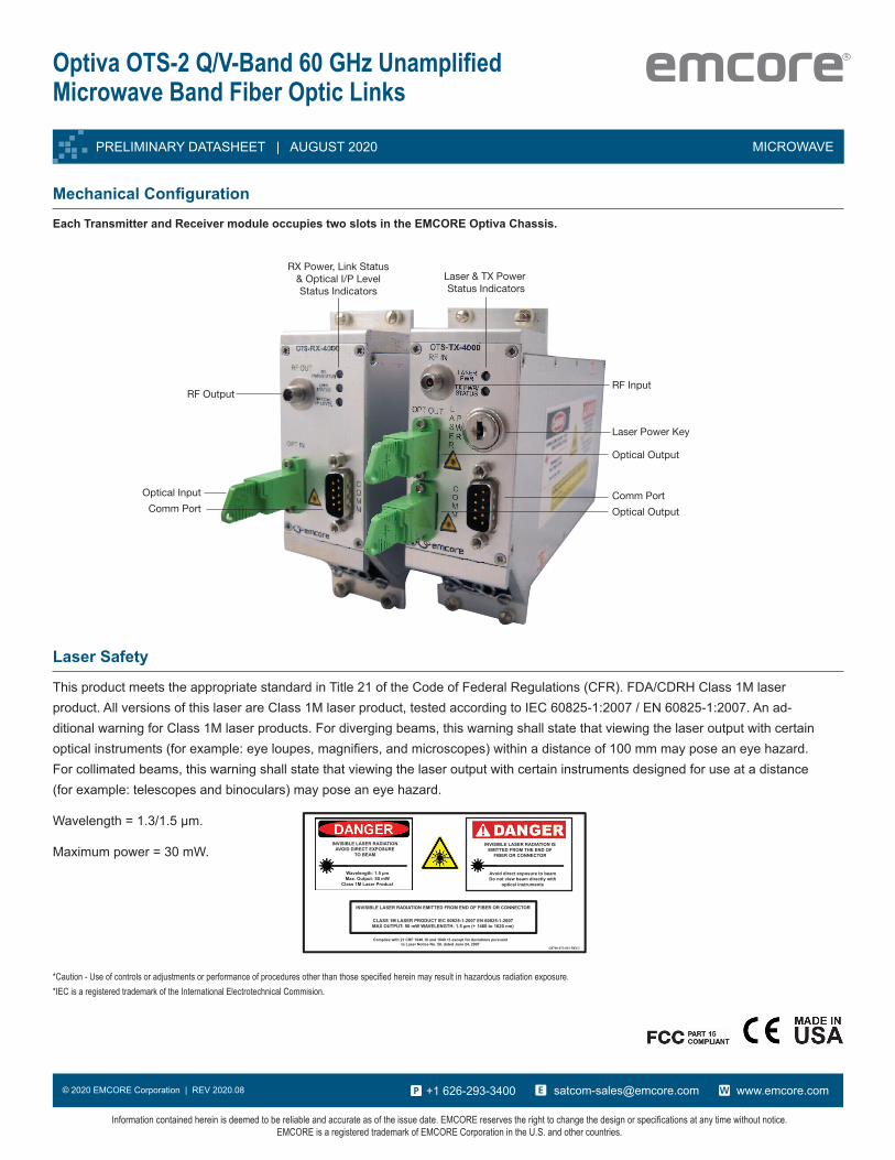
This product meets the appropriate standard in Title 21 of the Code of Federal Regulations (CFR). FDA/CDRH Class 1M laser product. All versions of this laser are Class 1M laser product, tested according to IEC 60825-1:2007 / EN 60825-1:2007. An ad-ditional warning for Class 1M laser products. For diverging beams, this warning shall state that viewing the laser output with certain optical instruments (for example: eye loupes, magnifiers, and microscopes) within a distance of 100 mm may pose an eye hazard. For collimated beams, this warning shall state that viewing the laser output with certain instruments designed for use at a distance (for example: telescopes and binoculars) may pose an eye hazard.
Wavelength = 1.3/1.5 μm.
Maximum power = 30 mW.
*Caution-Useofcontrolsoradjustmentsorperformanceofproceduresotherthanthosespecifiedhereinmayresultinhazardousradiationexposure.*IEC is a registered trademark of the International Electrotechnical Commision.
INVISIBLE LASER RADIATION AVOID DIRECT EXPOSURE
TO BEAM
Wavelength: 1.5 µmMax. Output: 50 mW
Class 1M Laser Product
INVISIBLE LASER RADIATION IS EMITTED FROM THE END OF
FIBER OR CONNECTOR
Avoid direct exposure to beamDo not view beam directly with
optical instruments
INVISIBLE LASER RADIATION EMITTED FROM END OF FIBER OR CONNECTOR
CLASS 1M LASER PRODUCT IEC 60825-1:2007 EN 60825-1:2007MAX OUTPUT: 50 mW WAVELENGTH: 1.5 µm (+ 1460 to 1620 nm)
Complies with 21 CRF 1040.10 and 1040.11 except for deviations pursuant to Laser Notice No. 50, dated June 24, 2007
G8760-073-001 REV.3
Laser Safety
Mechanical Configuration
Each Transmitter and Receiver module occupies two slots in the EMCORE Optiva Chassis.
RF Output
Optical Input
Laser & TX Power Status Indicators
Comm Port
RF Input
Laser Power Key
Optical Output
Comm Port
RX Power, Link Status& Optical I/P LevelStatus Indicators
TransmitterReceiver
Optical Output