Embed Size (px)
Citation preview
New Features
14.0
Created to address the needs of research scientists, photonic
engineers, professors and students; OptiSystem satisfies the
demand of users who are searching for a powerful yet easy to use
photonics system design tool.
Document revised: 7 Jan 2016
Key Features for OptiSystem 14
OptiSystem 14 includes several enhancements including a new C++ co-simulation component,
updates to our multimode component portfolio (to better support the analysis of spatial mode
multiplexed systems), the addition of star and circular QAM constellations for coherent
transmission systems, and improvements to our transmitter and receiver component portfolios.
Key new features include:
• The introduction of a new Cpp component and Cpp CoSimulation Visualizer to allow
users to import or build their own customized C++ algorithms/components and directly
co-simulate their customized models (using dynamic link libraries) with any other
OptiSystem component.
• The Universal DSP, Decision, QAM Sequence Generator and QAM Sequence Decoder
components have been updated to support a broader range of modulation formats,
including star and circular QAM constellation formats as well as 32-QAM, 128-QAM,
and 256-QAM constellations.
• Several enhancements have been made to the Multimode components library including
the introduction of a new Spatial Demultiplexer component, improvements to the
Erbium Doped MM Fiber, Ytterbium Doped MM Fiber, Measured-Index Multimode
Fiber and Parabolic-Index Multimode Fiber amplifier and fiber models (for modelling
spatial multiplexed systems and concatenated fibers) and the integration of LP mode
generators into our Spatial Transmitter components.
• Several components within the Transmitters and Receivers libraries have been
improved including the introduction of a new Spectral Light Source component,
improvements to the noise models in the APD and PIN components, the addition of
thermal noise models to our Analog to Digital and Digital to Analog components and
the addition of user-defined PAM amplitude maps to our PAM Coder and Decoder
components
• Other improvements include updates to our Measured Filter, Measured Optical Filter,
Lightwave Analyzer, View Signal Visualizer and Power Splitters; and the introduction
of a new Diffuse Channel component for the modeling of indoor optical wireless
systems.
Document revised: 7 Jan 2016
New library components and enhancements
Co-simulation capabilities: Cpp, Cpp CoSimulation Visualizer
We are pleased to announce the launch of our new Cpp component in OptiSystem 14. Designed
for users who wish to import or build their own customized C++ algorithms/components, the
Cpp component will allow for the direct co-simulation of customized models (using dynamic link
libraries) with any other OptiSystem component. It includes an open signal architecture
interface to allow users to input and/or output any of OptiSystem's signal types and complex
waveform data arrays.
In addition to the Cpp component, we have launched a new Visualizer, the Cpp CoSimulation
Visualizer. The new Cpp CoSimulation Visualizer’s primary function is to duplicate all the signals
that are designed to enter the Cpp component thus allowing for signal files to be loaded into the
component design project (without OptiSystem running) when running in debug mode.
For more information on this new powerful feature please visit: http:/optiwave.com/?p=28551
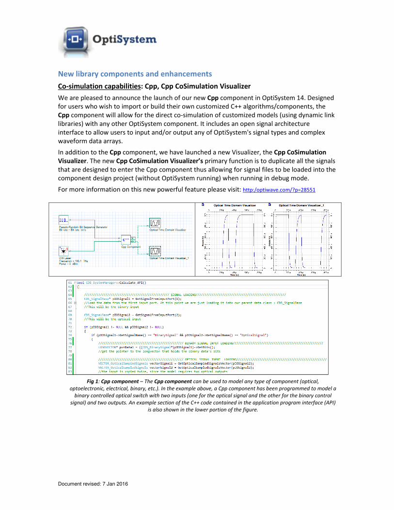
Fig 1: Cpp component – The Cpp component can be used to model any type of component (optical,
optoelectronic, electrical, binary, etc.). In the example above, a Cpp component has been programmed to model a
binary controlled optical switch with two inputs (one for the optical signal and the other for the binary control
signal) and two outputs. An example section of the C++ code contained in the application program interface (API)
is also shown in the lower portion of the figure.
Document revised: 7 Jan 2016
Transmitters and receiver design: Universal DSP, Decision, QAM coding update, PAM
coding update, ADC and DAC updates, TIA update, APD update, Spectral Light Source,
LED update
The Universal DSP and Decision components have been updated to support a broader range of
modulation formats, including:
• BPSK, QPSK, 8PSK, 16PSK
• 8QAM, 16QAM, 32QAM, 64QAM, 128QAM, 256QAM
In addition, for QAM modulation formats; star and circular constellation formats are now
supported.
The QAM Sequence Generator and QAM Sequence Decoder components now support the
definition of square, star, and circular constellation formats (with differential or gray coding).
All components which create or decode PAM sequences (PAM Sequence Generator, PAM Pulse
Generator, Electrical PAM Modulator, and PAM Sequence Decoder) now include the option to
import or update user-defined PAM amplitude maps (using the MxN parameters array feature).
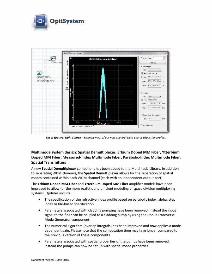
A new Spectral Light Source component has been added to the Transmitters/Optical Sources
library. Lorentzian, Gaussian or file-based (user-defined) spectral profiles can be created to
model various ambient light sources or LEDs.
The LED component has been updated to include the ability to import a user-defined spectral
profile (measured optical filter feature). Also the output power setting feature now includes the
ability to define the slope efficiency.
The APD component has been updated and includes the following new features:
• The thermal noise model has been updated to include the definition of thermal noise
based on temperature and load resistance.
• New results have been added for shot and thermal noise currents.
• A new parameter has been added to allow for the definition of noise bandwidth based
on the Effective noise bandwidth parameter.
The Transimpedance amplifier component now includes the ability to import measured
electrical filter data (frequency transfer function model)
A new thermal noise model has been added to the Analog to Digital and Digital to Analog
components, including new calculation results for thermal noise currents and quantization
noise.

Document revised: 7 Jan 2016
Fig 2: 112 Gbit/s 128 QAM – Example of a 112 Gbit/s, 128 QAM, dual polarization coherent transmission system
using our updated Universal DSP, Decision and QAM Coder/Decoder components.
Fig 3: 112 Gbit/s DP 16 QAM Star – Example of a 112 Gbit/s, 16 QAM Star, dual polarization coherent transmission
system using our updated Universal DSP, Decision and QAM Coder/Decoder components .
Document revised: 7 Jan 2016
Fig 4: Spectral Light Source – Example view of our new Spectral Light Source (Gaussian profile).
Multimode system design: Spatial Demultiplexer, Erbium Doped MM Fiber, Ytterbium
Doped MM Fiber, Measured-Index Multimode Fiber, Parabolic-Index Multimode Fiber,
Spatial Transmitters
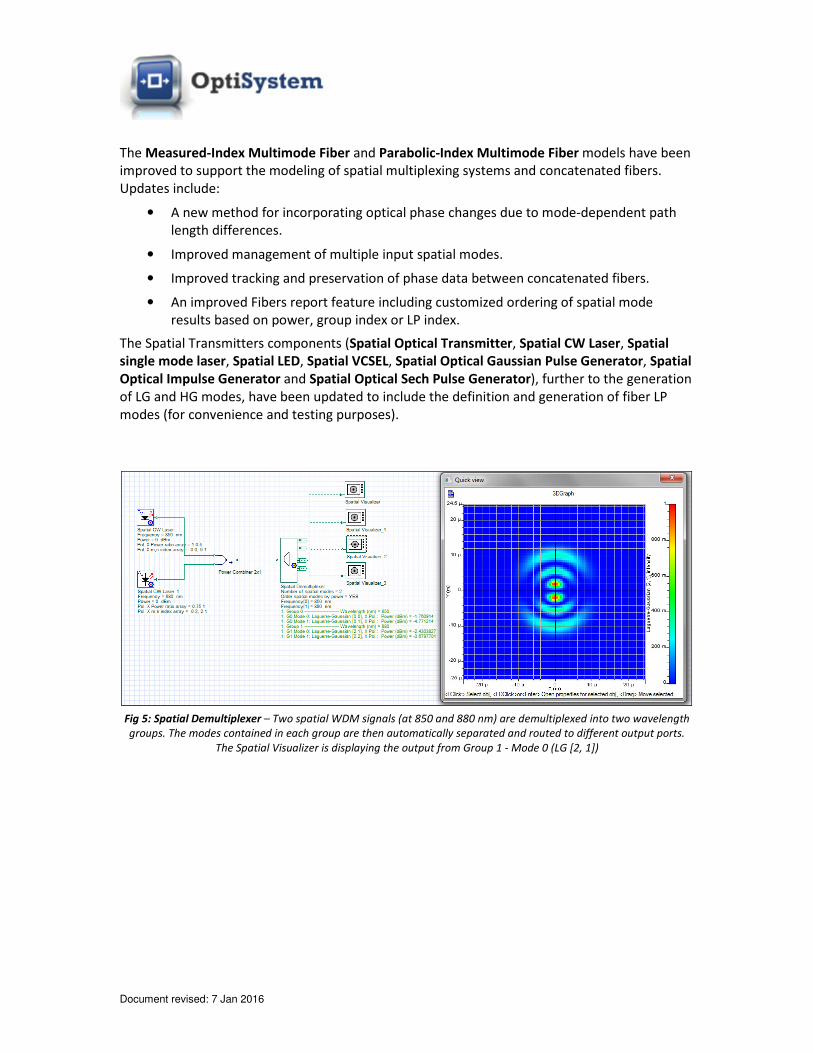
A new Spatial Demultiplexer component has been added to the Multimode Library. In addition
to separating WDM channels, the Spatial Demultiplexer allows for the separation of spatial
modes contained within each WDM channel (each with an independent output port).
The Erbium Doped MM Fiber and Ytterbium Doped MM Fiber amplifier models have been
improved to allow for the more realistic and efficient modeling of space division multiplexing
systems. Updates include:
• The specification of the refractive index profile based on parabolic index, alpha, step
index or file-based specification.
• Parameters associated with cladding pumping have been removed. Instead the input
signal to the fiber can be coupled to a cladding pump by using the Donut Transverse
Mode Generator component.
• The numerical algorithm (overlap integrals) has been improved and now applies a mode
dependent gain. Please note that the computation time may take longer compared to
the previous version of these components.
• Parameters associated with spatial properties of the pumps have been removed.
Instead the pumps can now be set up with spatial mode properties.
Document revised: 7 Jan 2016
The Measured-Index Multimode Fiber and Parabolic-Index Multimode Fiber models have been
improved to support the modeling of spatial multiplexing systems and concatenated fibers.
Updates include:
• A new method for incorporating optical phase changes due to mode-dependent path
length differences.
• Improved management of multiple input spatial modes.
• Improved tracking and preservation of phase data between concatenated fibers.
• An improved Fibers report feature including customized ordering of spatial mode
results based on power, group index or LP index.
The Spatial Transmitters components (Spatial Optical Transmitter, Spatial CW Laser, Spatial
single mode laser, Spatial LED, Spatial VCSEL, Spatial Optical Gaussian Pulse Generator, Spatial
Optical Impulse Generator and Spatial Optical Sech Pulse Generator), further to the generation
of LG and HG modes, have been updated to include the definition and generation of fiber LP
modes (for convenience and testing purposes).
Fig 5: Spatial Demultiplexer – Two spatial WDM signals (at 850 and 880 nm) are demultiplexed into two wavelength
groups. The modes contained in each group are then automatically separated and routed to different output ports.
The Spatial Visualizer is displaying the output from Group 1 - Mode 0 (LG [2, 1])
Document revised: 7 Jan 2016
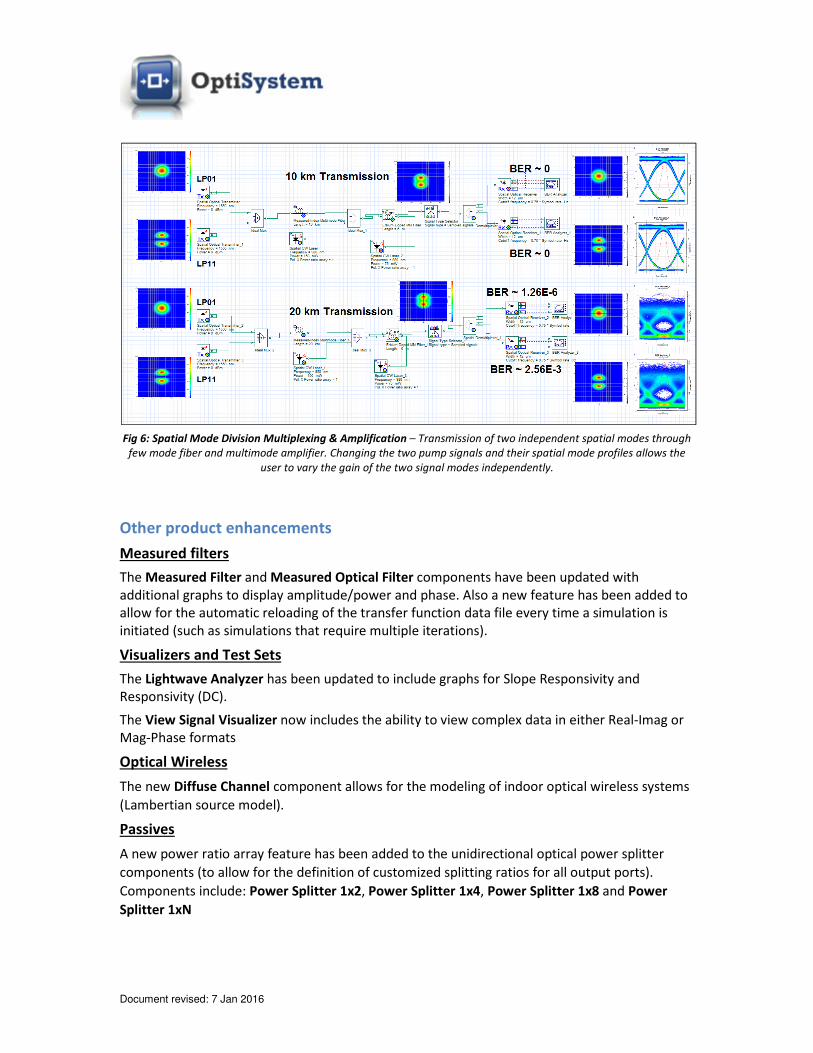
Fig 6: Spatial Mode Division Multiplexing & Amplification – Transmission of two independent spatial modes through
few mode fiber and multimode amplifier. Changing the two pump signals and their spatial mode profiles allows the
user to vary the gain of the two signal modes independently.
Other product enhancements
Measured filters
The Measured Filter and Measured Optical Filter components have been updated with
additional graphs to display amplitude/power and phase. Also a new feature has been added to
allow for the automatic reloading of the transfer function data file every time a simulation is
initiated (such as simulations that require multiple iterations).
Visualizers and Test Sets
The Lightwave Analyzer has been updated to include graphs for Slope Responsivity and
Responsivity (DC).
The View Signal Visualizer now includes the ability to view complex data in either Real-Imag or
Mag-Phase formats
Optical Wireless
The new Diffuse Channel component allows for the modeling of indoor optical wireless systems
(Lambertian source model).
Passives
A new power ratio array feature has been added to the unidirectional optical power splitter
components (to allow for the definition of customized splitting ratios for all output ports).
Components include: Power Splitter 1x2, Power Splitter 1x4, Power Splitter 1x8 and Power
Splitter 1xN
Document revised: 7 Jan 2016
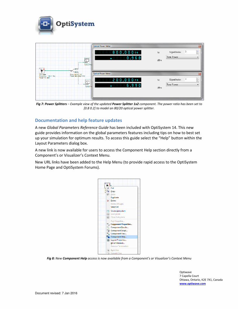
Fig 7: Power Splitters – Example view of the updated Power Splitter 1x2 component. The power ratio has been set to
[0.8 0.2] to model an 80/20 optical power splitter.
Documentation and help feature updates
A new Global Parameters Reference Guide has been included with OptiSystem 14. This new
guide provides information on the global parameters features including tips on how to best set
up your simulation for optimum results. To access this guide select the “Help” button within the
Layout Parameters dialog box.
A new link is now available for users to access the Component Help section directly from a
Component’s or Visualizer’s Context Menu.
New URL links have been added to the Help Menu (to provide rapid access to the OptiSystem
Home Page and OptiSystem Forums).
Fig 8: New Component Help access is now available from a Component’s or Visualizer’s Context Menu
Optiwave
7 Capella Court
Ottawa, Ontario, K2E 7X1, Canada
www.optiwave.com