Embed Size (px)
Citation preview

1Copyright © Infineon Technologies AG 2021. All rights reserved.2021-10-28
OPTIREG™ System Basis Chips Product Overview
October 2021

2Copyright © Infineon Technologies AG 2021. All rights reserved.2021-10-28
System Basis Chip (SBC)
Collaterals & Support Material
– Link to SBC family page– Automotive Power Selection Guide– Automotive Application Guide– Automotive In-Vehicle Networking
– Product Briefs – Selection Guides– Application Brochures– Presentations– Fighting Guides
Collaterals and Brochures
Technical Material
Evaluation Boards &
Software
Videos
– Application Notes– User Manual– Datasheets– PCB Design Data
– Evaluation BoardsSoftware:– SBC Config Wizard– Power Dissipation Tool– Bode Plot – CAN PN Wizard– SBC Microcontroller Library– Current Consumption Tool
– Technical Videos– eLearnings
Videos /
Distribution Trainings
FAQ– FAQ General SBC– FAQ Lite SBC– FAQ MR+ SBC
– Link to Videos– Link to eLearning
– Link to SBC family page– Lite SBC family page– Mid-Range+ SBC family page– DCDC+ SBC family page– Multi-CAN Power+ SBC family page
– Link to board pages– Link to software
– Link to SBC FAQ– Link to Lite SBC FAQ– Link to MR+ SBC FAQ

3Copyright © Infineon Technologies AG 2021. All rights reserved.2021-10-28
OPTIREG™
High performance discrete power portfolio and integrated system
solution out of one hand
High Performance
General Purpose
Voltage Trackers
Application Specific
Application Specific
(24 V)
Post Regulators
Buck Converter
Boost Converter
Buck Controller
Safe Computing
Safe Control
These linear power supply
solutions are suited for
body, infotainment, chassis,
safety, powertrain and
transmission applications
These switched mode
power supply solutions are
ideal for body, infotainment,
chassis and safety
applications.
OPTIREG™ SwitcherOPTIREG™ Linear OPTIREG™ PMIC System Basis Chips
These integrated power
supply solutions are
targeted for applications like
chassis, safety, powertrain
and transmission.
Lite SBC
DCDC+ SBC
Multi-CAN Power+ SBC
Mid-Range+ SBC
These high integration
solutions offer power
supply, communication,
diagnosis and supporting
feature in a single device

4Copyright © Infineon Technologies AG 2021. All rights reserved.2021-10-28
What is an SBC?
Supporting features
System supply
Diagnosis and supervision
Communication interface

5Copyright © Infineon Technologies AG 2021. All rights reserved.2021-10-28
SBCs – What? Where? Why? How?

6Copyright © Infineon Technologies AG 2021. All rights reserved.2021-10-28
Why should I use an SBC?
Space
saving
Energy
saving
High
system
reliability
Reduced
system
cost
Multiple
and flexible
designs
Power, communication, safety and support features are integrated into one
system solution reduced PCB by ~90% (e.g. 300mm² vs. 34mm² for Lite SBC)
Extend battery life with very low quiescent current modes and CAN Partial
Networking. Lowest Iq to achieve limitation of <100µA per ECU
Extensive diagnostics and protections are embedded within the SBC to
support FuSa requirements, reduce external component count, improve system
reliability in comparison to discrete solutions
Minimum number of components to reduce system and BOM cost (7 in 1).
Reducing Total Cost of Ownership by ~0.1 USD per ECU, due to less
active component (~0.014 USD per active component for assembly,
qualification, purchasing, optical insception, logistics, etc.)
Compatibility reduces development time and effort for SBC by 1-2 man
months for electronic design and 50% SPI configuration software development
Scalability (transceiver) nodes reduce customer effort in platform approach.
7Copyright © Infineon Technologies AG 2021. All rights reserved.2021-10-28
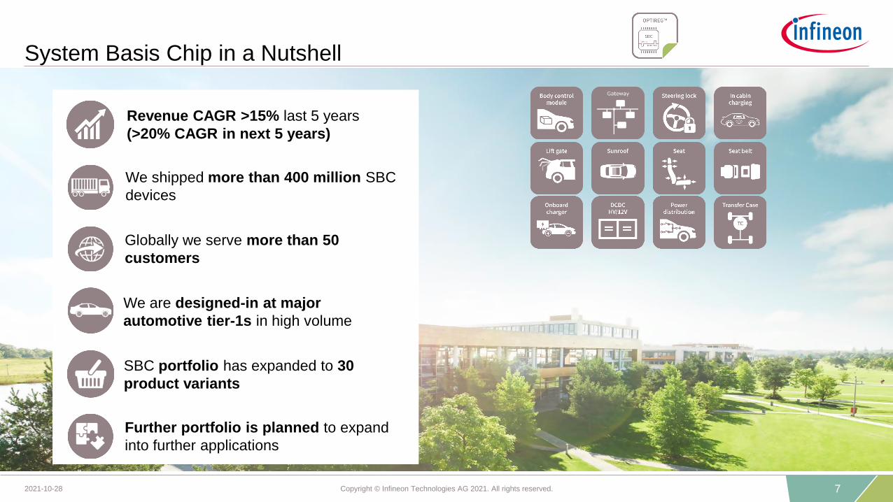
System Basis Chip in a Nutshell
SBC portfolio has expanded to 30
product variants
We are designed-in at major
automotive tier-1s in high volume
Further portfolio is planned to expand
into further applications
Globally we serve more than 50
customers
Revenue CAGR >15% last 5 years
(>20% CAGR in next 5 years)
We shipped more than 400 million SBC
devices

8Copyright © Infineon Technologies AG 2021. All rights reserved.2021-10-28
Lite SBCTLE9461/71
MR+ SBCTLE9261..3B
MCP+ SBCTLE9278B
DCDC SBCTLE9271..4
Infineon SBC’s offer most complete portfolio and
key differentiated USP’s
Unparalleled scalability across Product Families for fast time-to-market
Supports latest networking standards CAN FD up to 5Mbps & CAN PN supported
Component releases at all major OEMs
Hardware and Software scalability across 3 families
Software scalability across all 4 product families
BUS
BUS
LDO250mA
LDOExt. PnP
LDO100mA
BUS
Vbat
µC
Vcc1
RST
SPI
BUS
BUS
BUS
BUS
BUS
DCDC750mA
LDO100mA
VbatµC
Vcc1
RST
SPI
BUS
BUS
BUS
BUS
LDOExt. PnP
DCDC750mA µC
Vcc1
RST
SPI
LDO100mA
DCDC500mA
BUS
Vbat
µC
Vcc1
RST
SPI
LDO100mA
LDO150mA
BUS
Vbat
µC
Vcc1
RST
SPI
PPAP May 2020
9Copyright © Infineon Technologies AG 2021. All rights reserved.2021-10-28
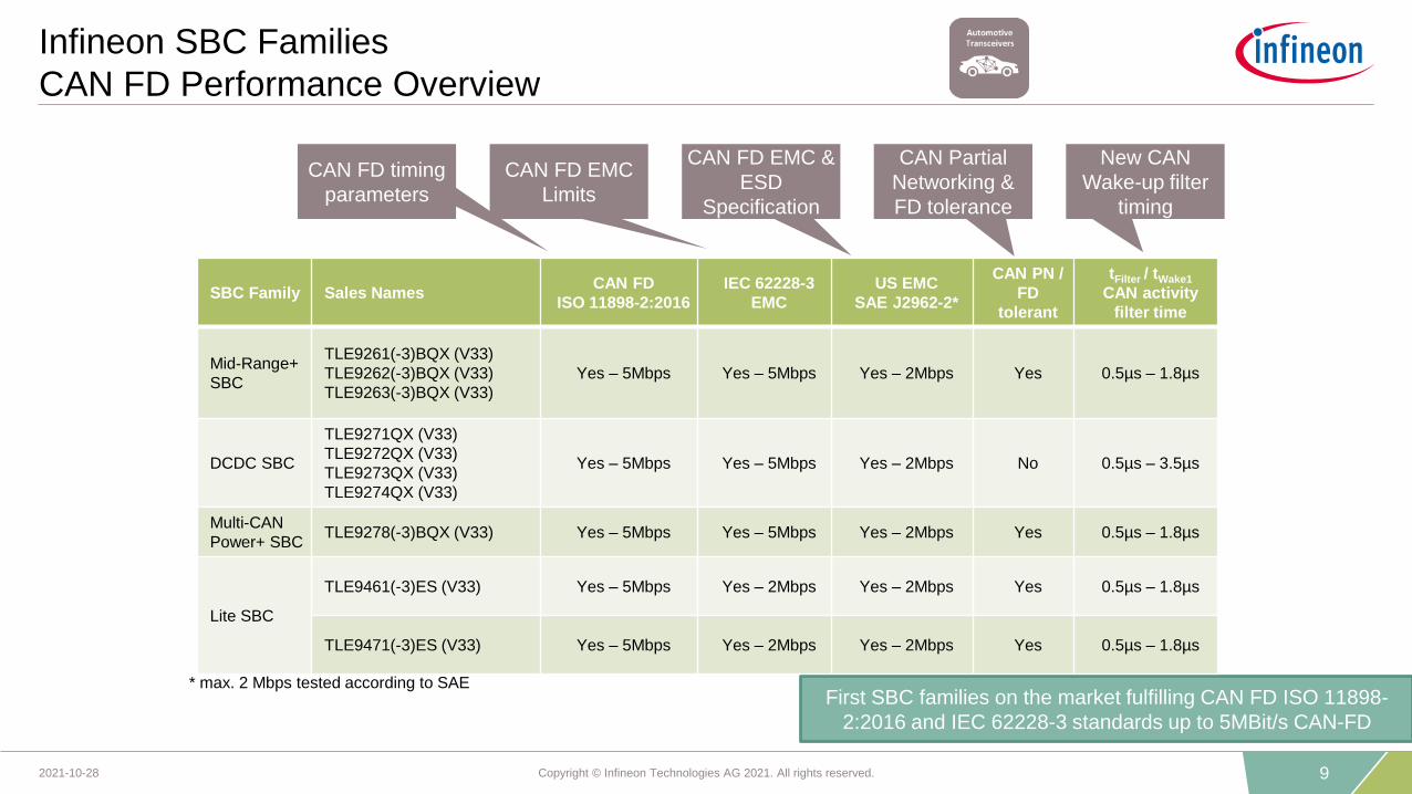
Infineon SBC Families
CAN FD Performance Overview
First SBC families on the market fulfilling CAN FD ISO 11898-
2:2016 and IEC 62228-3 standards up to 5MBit/s CAN-FD
SBC Family Sales NamesCAN FD
ISO 11898-2:2016
IEC 62228-3
EMC
US EMC
SAE J2962-2*
CAN PN /
FD
tolerant
tFilter / tWake1
CAN activity
filter time
Mid-Range+
SBC
TLE9261(-3)BQX (V33)
TLE9262(-3)BQX (V33)
TLE9263(-3)BQX (V33)
Yes – 5Mbps Yes – 5Mbps Yes – 2Mbps Yes 0.5µs – 1.8µs
DCDC SBC
TLE9271QX (V33)
TLE9272QX (V33)
TLE9273QX (V33)
TLE9274QX (V33)
Yes – 5Mbps Yes – 5Mbps Yes – 2Mbps No 0.5µs – 3.5µs
Multi-CAN
Power+ SBCTLE9278(-3)BQX (V33) Yes – 5Mbps Yes – 5Mbps Yes – 2Mbps Yes 0.5µs – 1.8µs
Lite SBC
TLE9461(-3)ES (V33) Yes – 5Mbps Yes – 2Mbps Yes – 2Mbps Yes 0.5µs – 1.8µs
TLE9471(-3)ES (V33) Yes – 5Mbps Yes – 2Mbps Yes – 2Mbps Yes 0.5µs – 1.8µs
* max. 2 Mbps tested according to SAE
CAN FD timing
parameters
CAN FD EMC
Limits
CAN FD EMC &
ESD
Specification
New CAN
Wake-up filter
timing
CAN Partial
Networking &
FD tolerance

10Copyright © Infineon Technologies AG 2021. All rights reserved.2021-10-28
System Basis Chips can be used in any ECU
in the car
Gateway(DCDC+, MCP+) Sunroof Module
(Lite, MR+)
Power Doors(Lite, MR+)
Seat Module(MR+)
Steering Column Lock(Lite, MR+)Light Control Unit
(Lite, MR+)
HVAC(Lite, MR+)
Body Control Module(Lite, MR+, DCDC+, MCP+)
Power Distribution Box(Lite, MR+, DCDC+, MCP+)
Body
Chassis &
Safety
Powertrain &
Infotainment
Belt Pretension(Lite)
Chassis Domain(MCP+)
Gear Shifter(Lite, MR+)
Wireless In-Cabin Charger(Lite)
Transfer Case(Lite, MR+)
On-Board Charger(Lite, MR+)
Telematics(DCDC+, MCP+)
Application examples

11Copyright © Infineon Technologies AG 2021. All rights reserved.2021-10-28
Lite LDO SBC – Overview
TLE9461(-3)ES (V33)
› 5V/3.3V Linear Regulator up to 150mA (Vcc1)
› 5V Linear Regulator (off-board protected) up to 100mA (Vcc2)
› CAN FD up to 5Mbps, CAN PN FD Tolerant (“-3” variants)
› 1x HV Wake input, Watchdog, Reset, Interrupt, Fail Output
› Charge Pump Output for Reverse Polarity Control
› Spread Spectrum for EMI mitigation
› Alternative Functions to Fail Output:
Configurable as Wake, Low-Side or High-Side Switch (up to 45mA) Low Power and Fail-
Safe Operating Modes
› Package: 8.65x6mm TSDSO-24
› Software Compatibility w/in TLE9x6y & TLE9x7y
Key Features
GND
SPI
Watchdog
RO
SPI
Configurable
Switch /
Input
WK
CAN TxD
RxD
VCC1Vbat
VCC2
CAN
Protocol
Handler
High
Precision
Clock
Frame
Compare
Logic
LDO2
LDO1
Charge
Pump
Reset
Wake
Input
State
Machine INT
VCP
Vbat
FO/GPIO
Application Examples
12Copyright © Infineon Technologies AG 2021. All rights reserved.2021-10-28
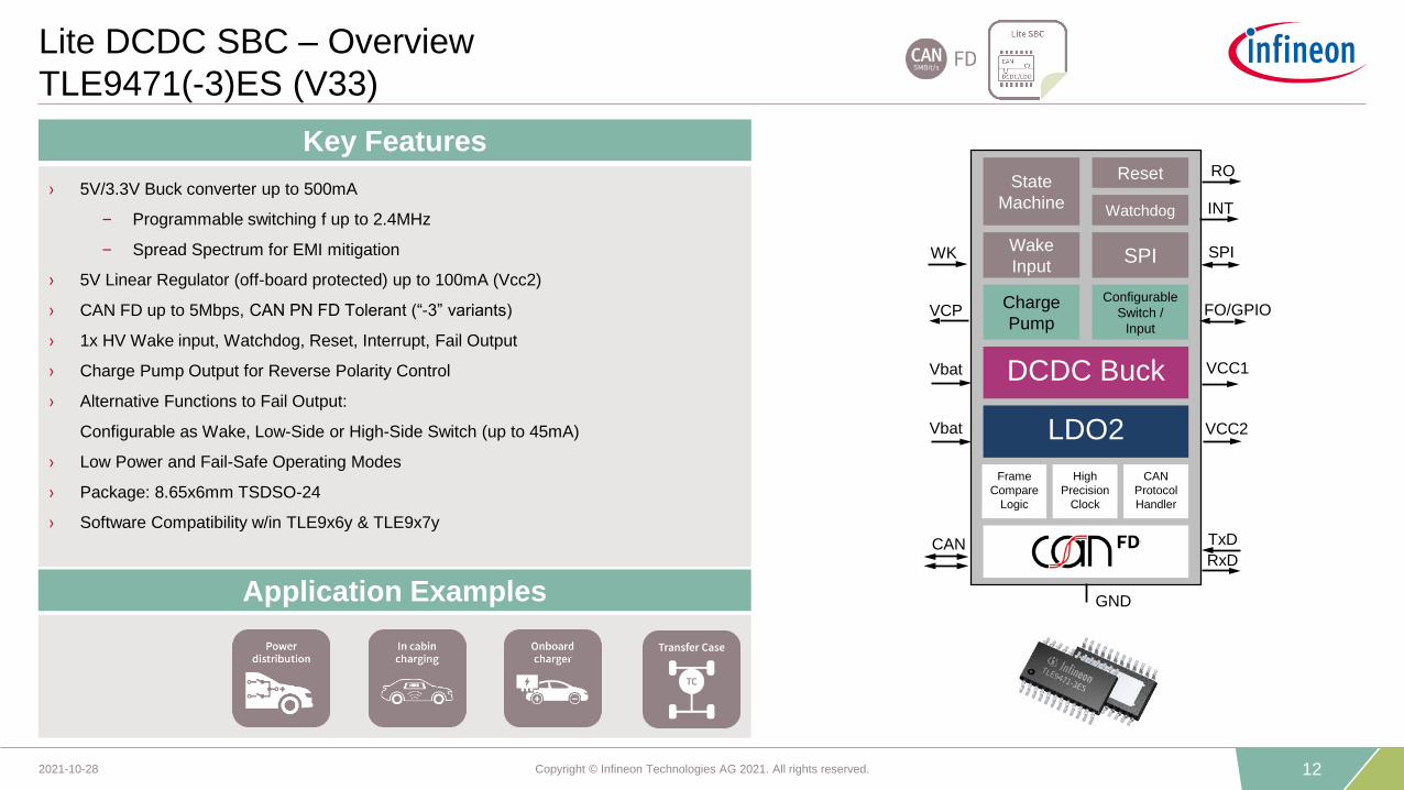
Lite DCDC SBC – Overview
TLE9471(-3)ES (V33)
› 5V/3.3V Buck converter up to 500mA
– Programmable switching f up to 2.4MHz
– Spread Spectrum for EMI mitigation
› 5V Linear Regulator (off-board protected) up to 100mA (Vcc2)
› CAN FD up to 5Mbps, CAN PN FD Tolerant (“-3” variants)
› 1x HV Wake input, Watchdog, Reset, Interrupt, Fail Output
› Charge Pump Output for Reverse Polarity Control
› Alternative Functions to Fail Output:
Configurable as Wake, Low-Side or High-Side Switch (up to 45mA)
› Low Power and Fail-Safe Operating Modes
› Package: 8.65x6mm TSDSO-24
› Software Compatibility w/in TLE9x6y & TLE9x7y
Key Features
Application Examples GND
SPI
Watchdog
RO
SPI
Configurable
Switch /
Input
WK
CAN TxD
RxD
VCC1Vbat
VCC2
CAN
Protocol
Handler
High
Precision
Clock
Frame
Compare
Logic
LDO2
DCDC Buck
Charge
Pump
Reset
Wake
Input
State
Machine INT
VCP
Vbat
FO/GPIO
13Copyright © Infineon Technologies AG 2021. All rights reserved.2021-10-28
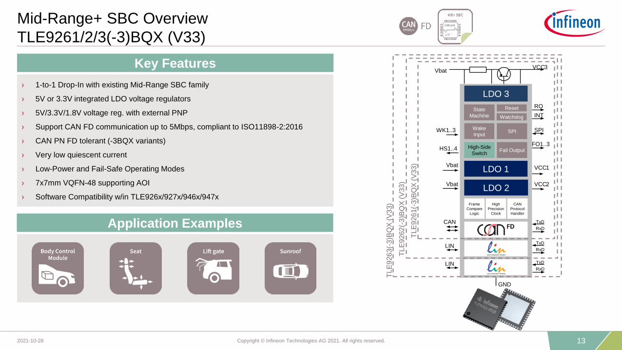
Mid-Range+ SBC Overview
TLE9261/2/3(-3)BQX (V33)
Application Examples
› 1-to-1 Drop-In with existing Mid-Range SBC family
› 5V or 3.3V integrated LDO voltage regulators
› 5V/3.3V/1.8V voltage reg. with external PNP
› Support CAN FD communication up to 5Mbps, compliant to ISO11898-2:2016
› CAN PN FD tolerant (-3BQX variants)
› Very low quiescent current
› Low-Power and Fail-Safe Operating Modes
› 7x7mm VQFN-48 supporting AOI
› Software Compatibility w/in TLE926x/927x/946x/947x
Key Features
GND
Reset
Fail Output
SPIWake
Input
LIN
CAN
FO1..3
RO
SPIWK1..3
State
Machine INT
LIN
VCC1LDO 1Vbat
LDO 2VCC2Vbat
High-Side
SwitchHS1..4
LDO 3
VCC3
CAN
Protocol
Handler
High
Precision
Clock
Frame
Compare
Logic
TxD
RxD
TxD
RxD
TxD
RxD
Vbat
TL
E9
26
3(-
3)B
QX
(V
33)
TL
E9
26
2(-
3)B
QX
(V
33)
TL
E9
26
1(-
3)B
QX
(V
33)
Watchdog

14Copyright © Infineon Technologies AG 2021. All rights reserved.2021-10-28
DCDC SBC Overview
TLE9271/2/3/4QX (V33)
Application Examples
› 5V(3.3V) BUCK converter up to 750mA
› 6.5V/8V BOOST controller (Vs) Additional 10V BOOST option for TLE9274QX (V33)NEW
› Switch f = 450kHz w/ edge shaping for low EMI
› LDO voltage regulator @ 5V up to 100mA
› CAN FD communication up to 5Mbps
› Very low quiescent current in PFM mode
› Low power and Fail-Safe Operating Mode
› 7x7mm VQFN-48 w/ exposed pad supporting AOI
› Software Compatibility w/in TLE926x/927x/946x/947x
Key Features
TL
E9
27
1Q
X (
V3
3)
TL
E9
27
2Q
X (
V3
3)
TL
E9
27
3(4
)QX
(V
33)
VCC1
GND
SPI
Reset
Wake input
LIN
CAN
RO
SPIWK
State
Machine INT
DCDC Buck
DCDC Boost
FO
LIN
LIN
Vbat
LIN
TxD
RxD
TxD
RxD
TxD
RxD
TxD
RxD
TxD
RxD
LDO VCC2Vbat
Vs
Watchdog
FO

15Copyright © Infineon Technologies AG 2021. All rights reserved.2021-10-28
Analog
Digital
Converter
Multi-CAN Power+ SBC Overview
TLE9278(-3)BQX (V33)
Application Example
› 5V/3.3V BUCK converter up to 750mA
› 6.5V/8V/10V/12V BOOST converter
› Switch f = 450kHz w/ edge shaping for low EMI
› 5V/3.3V/1.8V/1.2V LDO with external PNP
› Four ports CAN FD up to 5Mbps
› CAN PN FD Tolerant (“-3” variants)
› Battery Voltage Measurement interface w/ ADC
› Low Power and Fail-Safe Operating Mode
› 7x7mm VQFN-48 w/ exposed pad supporting AOI
› Software Compatibility w/in TLE926x/927x/946x/947x
Key Features
Vbat_sense
Vbat
State
Machine Watchdog
Wake Input
RO
SPIWK
INT
FO
GND
LDO
VEXT
DCDC Buck
DCDC Boost
VCC1
Vbat
Vs
CAN TxD
RxD
CAN TxD
RxD
CAN TxD
RxD
CAN TxD
RxD
Fail
Output
Reset
SPI
CAN
protocol
Handler
High
Precision
Clock
Frame
Compare
Logic
16Copyright © Infineon Technologies AG 2021. All rights reserved.2021-10-28
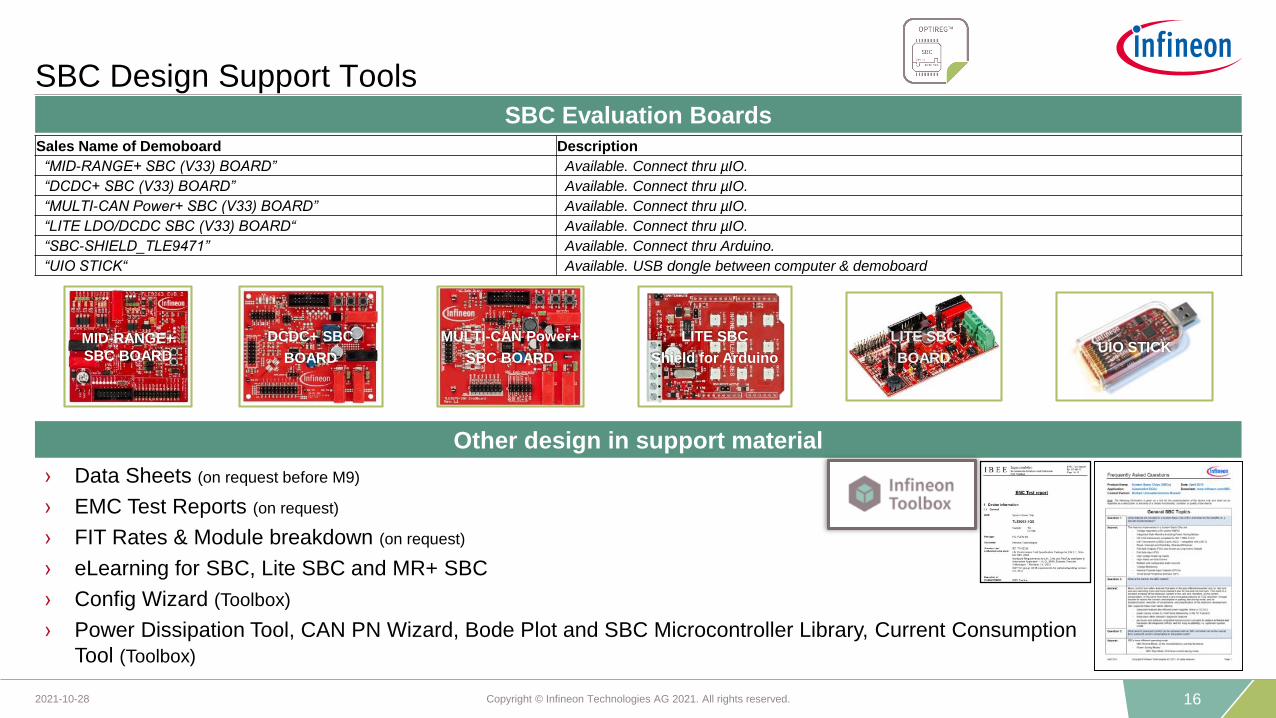
SBC Design Support ToolsSBC Evaluation Boards
Sales Name of Demoboard Description
“MID-RANGE+ SBC (V33) BOARD” Available. Connect thru µIO.
“DCDC+ SBC (V33) BOARD” Available. Connect thru µIO.
“MULTI-CAN Power+ SBC (V33) BOARD” Available. Connect thru µIO.
“LITE LDO/DCDC SBC (V33) BOARD“ Available. Connect thru µIO.
“SBC-SHIELD_TLE9471” Available. Connect thru Arduino.
“UIO STICK“ Available. USB dongle between computer & demoboard
› Data Sheets (on request before M9)
› EMC Test Reports (on request)
› FIT Rates & Module breakdown (on request)
› eLearning for SBC, Lite SBC and MR+ SBC
› Config Wizard (Toolbox)
› Power Dissipation Tool, CAN PN Wizard, Bode Plot and SBC Microcontroller Library, Current Consumption
Tool (Toolbox)
Other design in support material
MULTI-CAN Power+
SBC BOARD
MID-RANGE+
SBC BOARD
DCDC+ SBC
BOARD
LITE SBC
BOARDUIO STICK
LITE SBC
Shield for Arduino
17Copyright © Infineon Technologies AG 2021. All rights reserved.2021-10-28
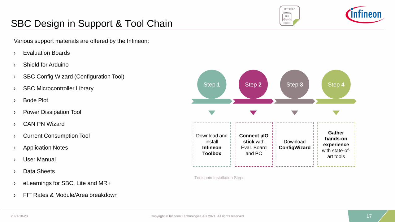
SBC Design in Support & Tool Chain
Various support materials are offered by the Infineon:
› Evaluation Boards
› Shield for Arduino
› SBC Config Wizard (Configuration Tool)
› SBC Microcontroller Library
› Bode Plot
› Power Dissipation Tool
› CAN PN Wizard
› Current Consumption Tool
› Application Notes
› User Manual
› Data Sheets
› eLearnings for SBC, Lite and MR+
› FIT Rates & Module/Area breakdown
Toolchain Installation Steps
Step 1 Step 2 Step 3 Step 4
Download and
install
Infineon
Toolbox
Connect µIO
stick with
Eval. Board
and PC
Download
ConfigWizard
Gather
hands-on
experience
with state-of-
art tools

18Copyright © Infineon Technologies AG 2021. All rights reserved.2021-10-28
Infineon SBC’s offers complete portfolio and key differentiated USP’s
for customers
› More than 80% board space reduction compared to discrete solution
› Unparalleled scalability across Product Families for fast time-to-market
› Infineon is FIRST in the market with SBCs compliant to latest CAN-FD
5Mbps ISO standard
› Interoperability and EMC compliance tests for component releases at all
major OEMs
› System Basis Chips enable high integration and smart energy
efficiency
SBC Portfolio scaled by Power and Comm. nodes Support latest advanced networking standards
Interoperability/Compliance tested for OEM release Infineon is your partner of choice for SBC’s
750mA
250mA
500mA
150mA